JP5309366B2 - Vacuum heat insulating material, heat insulating box, and manufacturing method of vacuum heat insulating material - Google Patents

Vacuum heat insulating material, heat insulating box, and manufacturing method of vacuum heat insulating material Download PDF

Info

Publication number
JP5309366B2
JP5309366B2 JP2009285169A JP2009285169A JP5309366B2 JP 5309366 B2 JP5309366 B2 JP 5309366B2 JP 2009285169 A JP2009285169 A JP 2009285169A JP 2009285169 A JP2009285169 A JP 2009285169A JP 5309366 B2 JP5309366 B2 JP 5309366B2
Authority
JP
Japan
Prior art keywords
fiber assembly
fiber
heat insulating
insulating material
vacuum heat
Prior art date
Legal status (The legal status is an assumption and is not a legal conclusion. Google has not performed a legal analysis and makes no representation as to the accuracy of the status listed.)
Expired - Fee Related
Application number
JP2009285169A
Other languages
Japanese (ja)
Other versions
JP2011127651A (en
Inventor
一正 藤村
光昭 中田
徹男 三谷
宗明 椋田
修一 岩田
京子 野村
尚平 安孫子
Current Assignee (The listed assignees may be inaccurate. Google has not performed a legal analysis and makes no representation or warranty as to the accuracy of the list.)
Mitsubishi Electric Corp
Original Assignee
Mitsubishi Electric Corp
Priority date (The priority date is an assumption and is not a legal conclusion. Google has not performed a legal analysis and makes no representation as to the accuracy of the date listed.)
Filing date
Publication date
Application filed by Mitsubishi Electric Corp filed Critical Mitsubishi Electric Corp
Priority to JP2009285169A priority Critical patent/JP5309366B2/en
Publication of JP2011127651A publication Critical patent/JP2011127651A/en
Application granted granted Critical
Publication of JP5309366B2 publication Critical patent/JP5309366B2/en
Expired - Fee Related legal-status Critical Current
Anticipated expiration legal-status Critical

Links

Images

Description

本発明は、真空断熱材、断熱箱および真空断熱材の製造方法に関し、特に樹脂繊維集合体を芯材とした真空断熱材と、その真空断熱材を用いた断熱箱と、その真空断熱材の製造方法とに関するものである。   The present invention relates to a vacuum heat insulating material, a heat insulating box, and a method for manufacturing a vacuum heat insulating material, in particular, a vacuum heat insulating material having a resin fiber assembly as a core material, a heat insulating box using the vacuum heat insulating material, and a vacuum heat insulating material. And a manufacturing method.

従来、繊維集合体を芯材とした真空断熱材が提案されている。たとえば、特開2007−32622号公報(特許文献1)には、バインダーを含まない無機繊維重合体からなる廃材および新材を内包材で包んだ芯材を有する真空断熱材が提案されている。また、特開2002−310384号公報(特許文献2)には、補強材と繊維材料を固形化するための結合材を含まない無機繊維集合体とを積層した芯材を有する真空断熱材が提案されている。   Conventionally, a vacuum heat insulating material using a fiber assembly as a core material has been proposed. For example, Japanese Unexamined Patent Application Publication No. 2007-32622 (Patent Document 1) proposes a vacuum heat insulating material having a core material in which a waste material and a new material made of an inorganic fiber polymer not containing a binder are wrapped with an inner packaging material. Japanese Patent Laid-Open No. 2002-310384 (Patent Document 2) proposes a vacuum heat insulating material having a core material in which a reinforcing material and an inorganic fiber aggregate not including a binder for solidifying the fiber material are laminated. Has been.

特開2007−32622号公報JP 2007-32622 A 特開2002−310384号公報JP 2002-310384 A

繊維集合体を芯材とした真空断熱材では、繊維集合体を一体化するための繊維結合加工が施さていない場合、製造時に繊維のほつれや脱落が生じるため、繊維集合体からなる芯材のハンドリング性が著しく低下する。   In a vacuum heat insulating material using a fiber assembly as a core material, if the fiber bonding process for integrating the fiber assembly is not performed, the fibers may fray or fall off during manufacture. Handleability is significantly reduced.

特開2007−32622号公報では、無機繊維重合体からなる廃材および新材がバインダーで固められていないため廃材と新材とを内包材に包む際のハンドリング性は向上していない。特開2002−310384号公報では、繊維材料を固形化するための結合材を含まないため補強材と無機繊維集合体とを外被材に挿入する際のハンドリング性は向上していない。   In Japanese Patent Application Laid-Open No. 2007-32622, since the waste material and the new material made of the inorganic fiber polymer are not hardened with the binder, the handling property when the waste material and the new material are wrapped in the inner packaging material is not improved. In Japanese Patent Laid-Open No. 2002-310384, since a binding material for solidifying a fiber material is not included, handling properties when inserting a reinforcing material and an inorganic fiber aggregate into an outer jacket material are not improved.

また、繊維集合体からなる芯材のハンドリング性を向上させるため、繊維集合体からなる芯材の形状を保持するように繊維集合体を一体化するための繊維結合加工が施される場合がある。この場合には、繊維同士の融着部分が芯材を貫通するように形成される。この繊維同士の融着部分において熱伝導が増大するため、真空断熱材の断熱性能が低下する。   Further, in order to improve the handling property of the core material made of the fiber assembly, fiber bonding processing for integrating the fiber assembly may be performed so as to maintain the shape of the core material made of the fiber assembly. . In this case, the fusion part between the fibers is formed so as to penetrate the core material. Since heat conduction increases at the fusion part between the fibers, the heat insulating performance of the vacuum heat insulating material is lowered.

本発明は、上記の課題を鑑みてなされたものであり、その目的は、樹脂繊維集合体のハンドリング性および断熱性能が高い真空断熱材、断熱箱および真空断熱材の製造方法を提供することである。   This invention is made | formed in view of said subject, The objective is providing the manufacturing method of a vacuum heat insulating material, a heat insulation box, and a vacuum heat insulating material with high handling property and heat insulation performance of a resin fiber aggregate. is there.

本発明の真空断熱材は、樹脂繊維集合体を真空密封した真空断熱材であって、樹脂繊維集合体は、第1繊維集合体と、第1繊維集合体を構成する樹脂材料よりガラス転移温度の低い結晶性の樹脂材料で構成された第2繊維集合体とを備え、第1繊維集合体に対して第2繊維集合体が熱融着されることにより構成されている。 The vacuum heat insulating material of the present invention is a vacuum heat insulating material obtained by vacuum-sealing a resin fiber assembly, and the resin fiber assembly has a glass transition temperature higher than that of the first fiber assembly and the resin material constituting the first fiber assembly. And a second fiber aggregate composed of a low crystalline resin material, and the second fiber aggregate is thermally fused to the first fiber aggregate.

本発明の真空断熱材の製造方法は、樹脂繊維集合体を真空密閉した真空断熱材の製造方法であって、樹脂繊維集合体の第1繊維集合体と、第1繊維集合体を構成する樹脂材料よ
りガラス転移温度の低い結晶性の樹脂材料で構成された第2繊維集合体とを積層させる工程と、第1繊維集合体と第2繊維集合体とが積層された状態において、第1繊維集合体に対して第2繊維集合体を熱融着させることにより、第1繊維集合体と第2繊維集合体とを一体化する工程とを備えている。
The method for manufacturing a vacuum heat insulating material according to the present invention is a method for manufacturing a vacuum heat insulating material in which a resin fiber assembly is vacuum-sealed, and includes a first fiber assembly of the resin fiber assembly and a resin constituting the first fiber assembly. In the process of laminating a second fiber aggregate composed of a crystalline resin material having a glass transition temperature lower than that of the material, and in a state where the first fiber aggregate and the second fiber aggregate are laminated, the first fiber A step of integrating the first fiber aggregate and the second fiber aggregate by thermally fusing the second fiber aggregate to the aggregate.

本発明によれば、第1繊維集合体に対して、第1繊維集合体を構成する樹脂材料よりガラス転移温度の低い樹脂材料で構成された第2繊維集合体が熱融着されるため、第1繊維集合体と第2繊維集合体とが一体化されることにより樹脂繊維集合体のハンドリング性を高くすることができる。また、第1繊維集合体には熱融着の貫通が発生しないので、樹脂繊維集合体の断熱性能を高くすることができる。   According to the present invention, the second fiber assembly composed of a resin material having a glass transition temperature lower than that of the resin material constituting the first fiber assembly is thermally fused to the first fiber assembly. The handling property of the resin fiber assembly can be enhanced by integrating the first fiber assembly and the second fiber assembly. In addition, since the first fiber aggregate does not penetrate through heat fusion, the heat insulation performance of the resin fiber aggregate can be enhanced.

本発明の実施の形態1における真空断熱材の概略断面図である。It is a schematic sectional drawing of the vacuum heat insulating material in Embodiment 1 of this invention. 本発明の実施の形態1における樹脂繊維集合体の概略断面図である。It is a schematic sectional drawing of the resin fiber assembly in Embodiment 1 of this invention. 本発明の実施の形態1における真空断熱材の製造方法を概略的に示す図である。It is a figure which shows schematically the manufacturing method of the vacuum heat insulating material in Embodiment 1 of this invention. 本発明の実施の形態1の変形例1における真空断熱材の製造方法を概略的に示す図である。It is a figure which shows roughly the manufacturing method of the vacuum heat insulating material in the modification 1 of Embodiment 1 of this invention. 本発明の実施の形態1の変形例2における真空断熱材の製造方法を概略的に示す図である。It is a figure which shows roughly the manufacturing method of the vacuum heat insulating material in the modification 2 of Embodiment 1 of this invention. 本発明の実施の形態2における真空断熱材の製造方法を概略的に示す図である。It is a figure which shows schematically the manufacturing method of the vacuum heat insulating material in Embodiment 2 of this invention. 本発明の実施の形態3における真空断熱材の製造方法を概略的に示す図である。It is a figure which shows schematically the manufacturing method of the vacuum heat insulating material in Embodiment 3 of this invention. 本発明の実施の形態5における断熱箱の概略断面図である。It is a schematic sectional drawing of the heat insulation box in Embodiment 5 of this invention.

以下、本発明の実施の形態について図に基づいて説明する。
(実施の形態1)
はじめに本発明の実施の形態1の真空断熱材の構成について説明する。
Hereinafter, embodiments of the present invention will be described with reference to the drawings.
(Embodiment 1)
First, the configuration of the vacuum heat insulating material according to Embodiment 1 of the present invention will be described.

図を参照して、真空断熱材10は、複数の樹脂繊維集合体1を有する芯材2と、水分吸着剤3と、外包材4とを主に有している。   Referring to the drawing, the vacuum heat insulating material 10 mainly includes a core material 2 having a plurality of resin fiber assemblies 1, a moisture adsorbent 3, and an outer packaging material 4.

外包材4に複数の樹脂繊維集合体1を有する芯材2と水分吸着剤3とが挿入されている。外包材4の内部は減圧されている。これにより真空断熱材10は樹脂繊維集合体1を真空密封するよう構成されている。外包材4の内部は、たとえば数Pa(パスカル)の真空度に減圧されている。外包材4の開口部はヒートシールにより接着されている。外包材4は、たとえば厚みが約6μmの金属箔層と熱可塑性ポリマー層とを有している。また、外包材4はガスバリア性を有している。   A core material 2 having a plurality of resin fiber assemblies 1 and a moisture adsorbent 3 are inserted into the outer packaging material 4. The inside of the outer packaging material 4 is decompressed. Thereby, the vacuum heat insulating material 10 is comprised so that the resin fiber assembly 1 may be vacuum-sealed. The inside of the outer packaging material 4 is decompressed to a degree of vacuum of, for example, several Pa (Pascal). The opening of the outer packaging material 4 is bonded by heat sealing. The outer packaging material 4 has, for example, a metal foil layer having a thickness of about 6 μm and a thermoplastic polymer layer. The outer packaging material 4 has gas barrier properties.

芯材2は、真空断熱材10において大気圧を支えて真空断熱材10内の空間を確保するよう構成されている。芯材2は、複数の樹脂繊維集合体1の積層体である。なお、芯材2は、複数の樹脂繊維集合体1に限定されず、1つの樹脂繊維集合体1からなっていてもよい。水分吸着剤3は、外包材4の内部の水分を吸着することにより真空断熱材10の真空度の経時劣化を抑制するよう構成されている。水分吸着剤3は、通気性のある袋に挿入されたCaO(酸化カルシウム)で構成されている。   The core material 2 is configured to support the atmospheric pressure in the vacuum heat insulating material 10 and secure a space in the vacuum heat insulating material 10. The core material 2 is a laminate of a plurality of resin fiber assemblies 1. The core material 2 is not limited to the plurality of resin fiber assemblies 1, and may consist of one resin fiber assembly 1. The moisture adsorbent 3 is configured to suppress deterioration with time of the vacuum degree of the vacuum heat insulating material 10 by adsorbing moisture inside the outer packaging material 4. The moisture adsorbent 3 is composed of CaO (calcium oxide) inserted in a breathable bag.

図2を参照して、樹脂繊維集合体1は、第1繊維集合体1aと、第2繊維集合体1bとを有している。第2繊維集合体1bは、第1繊維集合体1aを構成する樹脂材料よりガラス転移温度の低い樹脂材料で構成されている。第1繊維集合体1aに対して第2繊維集合体1bが熱融着されている。第1繊維集合体1aと第2繊維集合体1bとが熱融着部5により一体化されている。熱融着部5は、第2繊維集合体1bを貫通し、第1繊維集合体1aの界面と融着するよう構成されている。   With reference to FIG. 2, the resin fiber assembly 1 has a first fiber assembly 1a and a second fiber assembly 1b. The 2nd fiber aggregate 1b is comprised with the resin material whose glass transition temperature is lower than the resin material which comprises the 1st fiber aggregate 1a. The second fiber assembly 1b is heat-sealed to the first fiber assembly 1a. The first fiber assembly 1 a and the second fiber assembly 1 b are integrated by the heat-sealing part 5. The heat sealing | fusion part 5 penetrates the 2nd fiber assembly 1b, and is comprised so that it may melt | fuse with the interface of the 1st fiber assembly 1a.

第1繊維集合体1aの一方面および一方面に対向する他方面の両面に第2繊維集合体1bが接触している。なお、第1繊維集合体1aの一方面のみに第2繊維集合体1bが接触していてもよい。   The second fiber assembly 1b is in contact with both the one surface of the first fiber assembly 1a and the other surface opposite to the one surface. The second fiber assembly 1b may be in contact with only one surface of the first fiber assembly 1a.

第1繊維集合体1aは、たとえば、ガラス転移温度が70℃のPET(ポリエチレンテレフタレート)により構成されていてもよい。第2繊維集合体1bは、たとえば、ガラス転移温度が−20℃のPP(ポリプロピレン)により構成されていてもよい。なお、第1繊維集合体1aおよび第2繊維集合体1bを構成する樹脂繊維の組み合わせは、これに限定されず、第1繊維集合体1aを構成する樹脂材料のガラス転移温度より第2繊維集合体1bを構成する樹脂材料のガラス転移温度が低い関係にある樹脂材料が適用されていればよい。   The first fiber assembly 1a may be made of PET (polyethylene terephthalate) having a glass transition temperature of 70 ° C., for example. The second fiber assembly 1b may be made of PP (polypropylene) having a glass transition temperature of −20 ° C., for example. In addition, the combination of the resin fiber which comprises the 1st fiber assembly 1a and the 2nd fiber assembly 1b is not limited to this, The 2nd fiber assembly is based on the glass transition temperature of the resin material which comprises the 1st fiber assembly 1a. The resin material which has the relationship with the low glass transition temperature of the resin material which comprises the body 1b should just be applied.

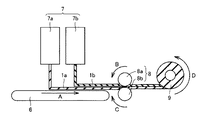
次に、本実施の形態の真空断熱材の製造方法について説明する。
図3を参照して、紡糸装置7の第2繊維紡糸装置7cから紡糸された繊維がコンベア6上に捕集される。第2繊維紡糸装置7cから紡糸され、コンベア6上に捕集された繊維によって第2繊維集合体1bが形成される。第2繊維集合体1bは、コンベア6によって、図中矢印A方向に任意の速度で搬送される。紡糸装置7の第1繊維紡糸装置7aから紡糸された繊維がコンベア6上に載置された第2繊維集合体1b上に捕集される。第1繊維紡糸装置7aから紡糸され、コンベア6上に載置された第2繊維集合体1a上に捕集された繊維によって第1繊維集合体1aが形成される。第1繊維集合体1aは、コンベア6によって、図中矢印A方向に任意の速度で搬送される。これにより、第1繊維集合体1aと第1繊維集合体1aを構成する樹脂材料よりガラス転移温度の低い樹脂材料で構成された第2繊維集合体1bとが積層される。
Next, the manufacturing method of the vacuum heat insulating material of this Embodiment is demonstrated.
With reference to FIG. 3, the fibers spun from the second fiber spinning device 7 c of the spinning device 7 are collected on the conveyor 6. A second fiber assembly 1b is formed by the fibers spun from the second fiber spinning device 7c and collected on the conveyor 6. The second fiber assembly 1b is conveyed by the conveyor 6 at an arbitrary speed in the direction of arrow A in the figure. The fibers spun from the first fiber spinning device 7 a of the spinning device 7 are collected on the second fiber assembly 1 b placed on the conveyor 6. A first fiber assembly 1 a is formed by fibers spun from the first fiber spinning device 7 a and collected on the second fiber assembly 1 a placed on the conveyor 6. The first fiber assembly 1a is conveyed by the conveyor 6 at an arbitrary speed in the direction of arrow A in the figure. Thereby, the 1st fiber assembly 1a and the 2nd fiber assembly 1b comprised by the resin material whose glass transition temperature is lower than the resin material which comprises the 1st fiber assembly 1a are laminated | stacked.

紡糸装置7の第2繊維紡糸装置7bから紡糸された繊維がコンベア6の上に載置された第1繊維集合体1a上に捕集される。第2繊維紡糸装置7bから紡糸され、第1繊維集合体1a上に捕集された繊維によって第2繊維集合体1bが形成される。第2繊維集合体1bは、コンベア6によって、図中矢印A方向に任意の速度で搬送される。これにより、第1繊維集合体1aと第2繊維集合体1bとは、第1繊維集合体1aが第2繊維集合体1bにより挟まれて積層される。   The fibers spun from the second fiber spinning device 7 b of the spinning device 7 are collected on the first fiber assembly 1 a placed on the conveyor 6. A second fiber assembly 1b is formed by fibers spun from the second fiber spinning device 7b and collected on the first fiber assembly 1a. The second fiber assembly 1b is conveyed by the conveyor 6 at an arbitrary speed in the direction of arrow A in the figure. Thereby, the first fiber assembly 1a and the second fiber assembly 1b are laminated with the first fiber assembly 1a sandwiched between the second fiber assemblies 1b.

第1繊維集合体1aと第2繊維集合体1bとは、第1繊維集合体1aが第2繊維集合体1bに挟まれて積層された状態で、コンベア6によって、エンボス熱ローラ8に向かって図中矢印A方向に搬送される。エンボス熱ローラ8は、第2繊維集合体1bを熱融着させるよう構成されており、第1繊維集合体1aが溶融せず、第2繊維集合体1bが溶融する温度に設定されている。たとえば、エンボス熱ローラ8の温度は、120度に設定されていてもよい。エンボス熱ローラ8の温度は、これに限定されず、第2繊維集合体1bのみを熱融着することのできる温度であればよい。   The first fiber assembly 1a and the second fiber assembly 1b are formed by the conveyor 6 toward the embossed heat roller 8 in a state where the first fiber assembly 1a is sandwiched and stacked between the second fiber assemblies 1b. It is conveyed in the direction of arrow A in the figure. The embossing heat roller 8 is configured to heat-fuse the second fiber aggregate 1b, and is set to a temperature at which the first fiber aggregate 1a does not melt and the second fiber aggregate 1b melts. For example, the temperature of the embossed heat roller 8 may be set to 120 degrees. The temperature of the embossing heat roller 8 is not limited to this, and may be a temperature at which only the second fiber assembly 1b can be heat-sealed.

エンボス熱ローラ8は2つのローラを有しており、一方のローラ8aが図中矢印B方向に回転しており、他方のローラ8bが図中矢印C方向に回転している。第1繊維集合体1aと第2繊維集合体1bとが積層された状態で、エンボス熱ローラ8のローラ8aとローラ8bとの間を通される。熱融着が第1繊維集合体1aを構成する樹脂材料よりガラス転移温度の低い樹脂材料で構成された第2繊維集合体1bを貫通し、第1繊維集合体1aの界面に達するよう熱融着が施される。一方、溶融した第2繊維集合体1bにより第1繊維集合体1aの界面は融着されるが、エンボス熱ローラ8の温度は第1繊維集合体1aを溶融しない温度に設定されるので、熱融着が第1繊維集合体1aを貫通することはない。このようにして、第1繊維集合体1aに対して第2繊維集合体1bが熱融着される。これにより、第1繊維集合体1aの両面に第2繊維集合体1bが熱融着されて、第1繊維集合体1aと第2繊維集合体1bとが一体化される。   The embossed heat roller 8 has two rollers, one roller 8a rotating in the direction of arrow B in the figure, and the other roller 8b rotating in the direction of arrow C in the figure. In a state where the first fiber assembly 1a and the second fiber assembly 1b are laminated, the embossed heat roller 8 is passed between the rollers 8a and 8b. The heat fusion passes through the second fiber assembly 1b made of a resin material having a glass transition temperature lower than that of the resin material constituting the first fiber assembly 1a, and reaches the interface of the first fiber assembly 1a. Wear is given. On the other hand, the interface of the first fiber assembly 1a is fused by the melted second fiber assembly 1b, but the temperature of the embossing heat roller 8 is set to a temperature at which the first fiber assembly 1a is not melted. The fusion does not penetrate through the first fiber assembly 1a. In this way, the second fiber assembly 1b is heat-sealed to the first fiber assembly 1a. Thereby, the 2nd fiber assembly 1b is heat-sealed on both surfaces of the 1st fiber assembly 1a, and the 1st fiber assembly 1a and the 2nd fiber assembly 1b are integrated.

上述の真空断熱材10の製造方法では、第1繊維集合体1aおよび第2繊維集合体1bの紡糸と、紡糸された第1繊維集合体1aおよび第2繊維集合体1bの一体化とが連続的に行われる。また、樹脂繊維集合体1における第1繊維集合体1aの割合を第2繊維集合体1bの割合よりも増やしてもよい。   In the manufacturing method of the vacuum heat insulating material 10 described above, the spinning of the first fiber assembly 1a and the second fiber assembly 1b and the integration of the spun first fiber assembly 1a and the second fiber assembly 1b are continuous. Done. Moreover, you may increase the ratio of the 1st fiber assembly 1a in the resin fiber assembly 1 rather than the ratio of the 2nd fiber assembly 1b.

第1繊維集合体1aと第2繊維集合体1bとが一体化された樹脂繊維集合体1は、図中矢印D方向に回転する巻き取りローラ9によって巻き取られる。巻き取りローラ9によって巻き取られた樹脂繊維集合体1が任意の大きさに切り取られる。   The resin fiber assembly 1 in which the first fiber assembly 1a and the second fiber assembly 1b are integrated is wound up by a winding roller 9 that rotates in the direction of arrow D in the figure. The resin fiber assembly 1 taken up by the take-up roller 9 is cut into an arbitrary size.

図1を参照して、複数の樹脂繊維集合体1が水分吸着剤3とともに外包材4に挿入される。外包材4の内部が減圧され、外包材4の開口部がヒートシールにより接着される。これにより、外包材4に樹脂繊維集合体1が真空密閉される。外包材4に樹脂繊維集合体1が真空密閉されることにより真空断熱材10が形成される。   Referring to FIG. 1, a plurality of resin fiber assemblies 1 are inserted into an outer packaging material 4 together with a moisture adsorbent 3. The inside of the outer packaging material 4 is decompressed, and the opening of the outer packaging material 4 is bonded by heat sealing. Thereby, the resin fiber assembly 1 is vacuum-sealed on the outer packaging material 4. A vacuum heat insulating material 10 is formed by vacuum-sealing the resin fiber assembly 1 on the outer packaging material 4.

続いて、本実施の形態の変形例1の真空断熱材の製造方法について説明する。
本実施の形態の変形例1の真空断熱材の製造方法では、上記の真空断熱材の製造方法と比較して、第2繊維紡糸装置7cを有していない点で主に異なっている。
Then, the manufacturing method of the vacuum heat insulating material of the modification 1 of this Embodiment is demonstrated.
The method for manufacturing a vacuum heat insulating material according to Modification 1 of the present embodiment is mainly different from the method for manufacturing a vacuum heat insulating material in that the second fiber spinning device 7c is not provided.

図4を参照して、本実施の形態の変形例1の真空断熱材の製造方法では、紡糸装置7の第1繊維紡糸装置7aから紡糸された繊維がコンベア6上に捕集される。第1繊維紡糸装置7aから紡糸され、コンベア6上に捕集された繊維によって第1繊維集合体1aが形成される。第1繊維集合体1aは、コンベア6によって、図中矢印A方向に任意の速度で搬送される。   With reference to FIG. 4, in the method for manufacturing a vacuum heat insulating material according to the first modification of the present embodiment, fibers spun from the first fiber spinning device 7 a of the spinning device 7 are collected on the conveyor 6. A first fiber assembly 1 a is formed by fibers spun from the first fiber spinning device 7 a and collected on the conveyor 6. The first fiber assembly 1a is conveyed by the conveyor 6 at an arbitrary speed in the direction of arrow A in the figure.

紡糸装置7の第2繊維紡糸装置7bから紡糸された繊維がコンベア6上に載置された第1繊維集合体1a上に捕集される。第2繊維紡糸装置7bから紡糸され、第1繊維集合体1a上に捕集された繊維によって第2繊維集合体1bが形成される。第2繊維集合体1bは、コンベア6によって、図中矢印A方向に任意の速度で搬送される。これにより、第1繊維集合体1aと第1繊維集合体1aを構成する樹脂材料よりガラス転移温度の低い樹脂材料で構成された第2繊維集合体1bとが積層される。   The fibers spun from the second fiber spinning device 7 b of the spinning device 7 are collected on the first fiber assembly 1 a placed on the conveyor 6. A second fiber assembly 1b is formed by fibers spun from the second fiber spinning device 7b and collected on the first fiber assembly 1a. The second fiber assembly 1b is conveyed by the conveyor 6 at an arbitrary speed in the direction of arrow A in the figure. Thereby, the 1st fiber assembly 1a and the 2nd fiber assembly 1b comprised by the resin material whose glass transition temperature is lower than the resin material which comprises the 1st fiber assembly 1a are laminated | stacked.

第1繊維集合体1aと第2繊維集合体1bとが積層された状態で、エンボス熱ローラ8のローラ8aとローラ8bとの間を通されて第1繊維集合体1aに対して第2繊維集合体1bが熱融着される。これにより、第1繊維集合体1aの片面に第2繊維集合体1bが熱融着されて、第1繊維集合体1aと第2繊維集合体1bとが一体化される。なお、これ以外の製造方法は、上記の真空断熱材の製造方法と同様であるため同一の要素については同一の符号を付し、その説明を繰り返さない。   In a state where the first fiber assembly 1a and the second fiber assembly 1b are laminated, the second fiber is passed between the rollers 8a and 8b of the embossing heat roller 8 and the second fiber assembly 1a. The assembly 1b is heat-sealed. Thereby, the 2nd fiber assembly 1b is heat-seal | fused to the single side | surface of the 1st fiber assembly 1a, and the 1st fiber assembly 1a and the 2nd fiber assembly 1b are integrated. In addition, since the manufacturing method other than this is the same as the manufacturing method of said vacuum heat insulating material, the same code | symbol is attached | subjected about the same element and the description is not repeated.

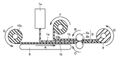
続いて、本実施の形態の変形例2の真空断熱材の製造方法について説明する。
本実施の形態の変形例1の真空断熱材の製造方法では、上記の真空断熱材の製造方法と比較して、第1繊維紡糸装置7aを有しておらず、繊維結合加工された第1繊維集合体1aが巻き取られた回転ロール10aを有している点で主に異なっている。
Then, the manufacturing method of the vacuum heat insulating material of the modification 2 of this Embodiment is demonstrated.
In the manufacturing method of the vacuum heat insulating material of the modification 1 of this Embodiment, compared with the manufacturing method of said vacuum heat insulating material, it does not have the 1st fiber spinning apparatus 7a, but the 1st fiber-bonding process was carried out. This is mainly different in that the fiber assembly 1a has a rotary roll 10a wound up.

図5を参照して、紡糸装置7の第2繊維紡糸装置7cから紡糸された繊維がコンベア6上に捕集される。第2繊維紡糸装置7cから紡糸され、コンベア6上に捕集された繊維によって第2繊維集合体1bが形成される。第2繊維集合体1bは、コンベア6によって、図中矢印A方向に任意の速度で搬送される。   Referring to FIG. 5, the fibers spun from the second fiber spinning device 7 c of the spinning device 7 are collected on the conveyor 6. A second fiber assembly 1b is formed by the fibers spun from the second fiber spinning device 7c and collected on the conveyor 6. The second fiber assembly 1b is conveyed by the conveyor 6 at an arbitrary speed in the direction of arrow A in the figure.

第1繊維集合体1aは繊維結合加工されている。繊維結合加工された第1繊維集合体1aが回転ロール10aに巻き取られている。回転ロール10aから繊維結合加工された第1繊維集合体1aがコンベア6上に載置された第2繊維集合体1a上に図中矢印E方向に巻き出される。繊維結合加工された第1繊維集合体1aは、コンベア6によって、図中矢印A方向に任意の速度で搬送される。これにより、繊維結合加工された第1繊維集合体1aと第1繊維集合体1aを構成する樹脂材料よりガラス転移温度の低い樹脂材料で構成された第2繊維集合体1bとが積層される。   The first fiber assembly 1a is fiber-bonded. The first fiber assembly 1a subjected to the fiber bonding process is wound around the rotary roll 10a. The first fiber assembly 1a fiber-bonded from the rotating roll 10a is unwound in the direction of arrow E in the figure on the second fiber assembly 1a placed on the conveyor 6. The first fiber assembly 1a subjected to the fiber bonding process is conveyed by the conveyor 6 at an arbitrary speed in the direction of arrow A in the figure. Thereby, the 1st fiber assembly 1a fiber-bonded and the 2nd fiber assembly 1b comprised by the resin material whose glass transition temperature is lower than the resin material which comprises the 1st fiber assembly 1a are laminated | stacked.

紡糸装置7の第2繊維紡糸装置7bから紡糸された繊維がコンベア6の上に載置された繊維結合加工された第1繊維集合体1a上に捕集される。第2繊維紡糸装置7bから紡糸され、繊維結合加工された第1繊維集合体1a上に捕集された繊維によって第2繊維集合体1bが形成される。第2繊維集合体1bは、コンベア6によって、図中矢印A方向に任意の速度で搬送される。これにより、繊維結合加工された第1繊維集合体1aと第2繊維集合体1bとは、繊維結合加工された第1繊維集合体1aが第2繊維集合体1bにより挟まれて積層される。   The fibers spun from the second fiber spinning device 7b of the spinning device 7 are collected on the first fiber aggregate 1a subjected to fiber bonding and placed on the conveyor 6. A second fiber assembly 1b is formed by the fibers collected on the first fiber assembly 1a spun from the second fiber spinning device 7b and subjected to fiber bonding. The second fiber assembly 1b is conveyed by the conveyor 6 at an arbitrary speed in the direction of arrow A in the figure. As a result, the first fiber assembly 1a and the second fiber assembly 1b that have been subjected to fiber bonding are stacked such that the first fiber assembly 1a that has been subjected to fiber bonding is sandwiched between the second fiber assemblies 1b.

繊維結合加工された第1繊維集合体1aと第2繊維集合体1bとが積層された状態で、エンボス熱ローラ8のローラ8aとローラ8bとの間を通されて繊維結合加工された第1繊維集合体1aに対して第2繊維集合体1bが熱融着される。これにより、繊維結合加工された第1繊維集合体1aの両面に第2繊維集合体1bが熱融着されて、繊維結合加工された第1繊維集合体1aと第2繊維集合体1bとが一体化される。なお、これ以外の製造方法は、上記の真空断熱材の製造方法と同様であるため同一の要素については同一の符号を付し、その説明を繰り返さない。   In a state where the first fiber assembly 1a and the second fiber assembly 1b that have been subjected to fiber bonding are stacked, the first fiber assembly that has been subjected to fiber bonding by passing between the rollers 8a and 8b of the embossed heat roller 8 The second fiber assembly 1b is heat-sealed to the fiber assembly 1a. As a result, the second fiber assembly 1b is heat-sealed to both surfaces of the fiber-bonded first fiber assembly 1a, so that the fiber-bonded first fiber assembly 1a and the second fiber assembly 1b Integrated. In addition, since the manufacturing method other than this is the same as the manufacturing method of said vacuum heat insulating material, the same code | symbol is attached | subjected about the same element and the description is not repeated.

なお、繊維結合加工としては、エンボスローラなど熱により結合させる「サーマルボンド法」が一般的であるが、本実施の形態における繊維結合加工は「サーマルボンド法」のみに限られない。接着剤により結合させる「ケミカルボンド法」、かえしのある針を突き刺して機械的に結合させる「ニードルパンチ法」、高圧水流により繊維を絡み合わせる「スパンレース法」、加熱蒸気により結合させる「スチームジェット法」など繊維を結合させ同効果を得られる加工であればよい。   As the fiber bonding process, a “thermal bond method” in which bonding is performed by heat such as an embossing roller is common, but the fiber bonding process in the present embodiment is not limited to the “thermal bond method”. "Chemical bond method" that is bonded by an adhesive, "needle punch method" that is mechanically bonded by sticking a needle with a barb, "span lace method" in which fibers are entangled by a high-pressure water stream, and "steam jet" that is bonded by heated steam Any method that can bind the fibers and obtain the same effect may be used.

なお、本実施の形態の真空断熱材10の製造方法としては、図3に示す第2繊維紡糸装置7cから紡糸される繊維を構成する樹脂材料を、第2繊維紡糸装置7bから紡糸される繊維を構成する樹脂材料と異なる樹脂材料としてもよい。そして、第2繊維集合体1bが溶融する温度に設定されたエンボス熱ローラ8により第1繊維集合体1aと第2繊維集合体1bとが一体化されて、巻き取りローラ9により巻き取られてもよい。   In addition, as a manufacturing method of the vacuum heat insulating material 10 of this Embodiment, the fiber which spins the resin material which comprises the fiber spun from the 2nd fiber spinning apparatus 7c shown in FIG. 3 from the 2nd fiber spinning apparatus 7b is shown. It is good also as a resin material different from the resin material which comprises. And the 1st fiber assembly 1a and the 2nd fiber assembly 1b are integrated by the embossing heat roller 8 set to the temperature which the 2nd fiber assembly 1b fuse | melts, and it is wound up by the winding roller 9 Also good.

次に、本実施の形態の作用効果について説明する。
本実施の形態の真空断熱材10によれば、第1繊維集合体1aに対して、第1繊維集合体1aを構成する樹脂材料よりガラス転移温度の低い樹脂材料で構成された第2繊維集合体1bが熱融着されるため、熱融着部5が第2繊維集合体1bを貫通し、第1繊維集合体1aの界面に達するまで形成される。これにより、第2繊維集合体1bがしっかりと熱融着される。そのため、樹脂繊維集合体1の第2繊維集合体1b側では、繊維のほつれや脱落を抑制することができる。
Next, the effect of this Embodiment is demonstrated.
According to the vacuum heat insulating material 10 of this Embodiment, the 2nd fiber assembly comprised with the resin material whose glass transition temperature is lower than the resin material which comprises the 1st fiber assembly 1a with respect to the 1st fiber assembly 1a. Since the body 1b is heat-sealed, the heat-sealing part 5 is formed until it penetrates the second fiber assembly 1b and reaches the interface of the first fiber assembly 1a. Thereby, the 2nd fiber assembly 1b is firmly heat-sealed. Therefore, on the second fiber assembly 1b side of the resin fiber assembly 1, fraying and dropping of the fibers can be suppressed.

また、第2繊維集合体1b側で繊維のほつれや脱落を抑制することができるため、樹脂繊維集合体1全体としても、繊維のほつれや脱落を抑制することができる。たとえば、熱融着部5により一体化された樹脂繊維集合体1を巻き取りローラ9で巻き取った後、必要な大きさに切り出すために巻き戻す際に繊維のほつれや脱落が生じることを抑制することができる。また、樹脂繊維集合体1を外包材4に挿入する際に繊維のほつれや脱落が生じることを抑制することができる。よって、樹脂繊維集合体1のハンドリング性を高くすることができる。   Moreover, since the fraying and dropping of the fibers can be suppressed on the second fiber assembly 1b side, the fraying and dropping of the fibers can also be suppressed as the entire resin fiber assembly 1. For example, after winding up the resin fiber assembly 1 integrated by the heat-sealing part 5 with the winding roller 9, it is possible to prevent the fibers from fraying or dropping off when being rewound to cut out to the required size. can do. Further, when the resin fiber assembly 1 is inserted into the outer packaging material 4, it is possible to prevent the fibers from fraying or falling off. Therefore, the handling property of the resin fiber assembly 1 can be increased.

一方、第1繊維集合体1aは第2繊維集合体1bよりガラス転移温度が高い樹脂材料で構成されているため、熱融着部5は第1繊維集合体1aの界面を融着するが、第1繊維集合体1aを貫通することはない。したがって、第1繊維集合体1aの内部に熱融着の貫通が発生しないため、断熱性能の低下を抑制することができる。これにより、樹脂繊維集合体1の断熱性能を高くすることができる。   On the other hand, since the first fiber assembly 1a is made of a resin material having a glass transition temperature higher than that of the second fiber assembly 1b, the heat fusion part 5 fuses the interface of the first fiber assembly 1a. It does not penetrate the first fiber assembly 1a. Therefore, since the penetration of heat fusion does not occur inside the first fiber assembly 1a, it is possible to suppress a decrease in heat insulation performance. Thereby, the heat insulation performance of the resin fiber assembly 1 can be enhanced.

また、第1繊維集合体1aの一方面および一方面に対向する他方面の両面に第2繊維集合体1bが接触していてもよい。これにより、樹脂繊維集合体1の両面において繊維のほつれや脱落が生じることを抑制できるので、ハンドリング性をより高くすることができる。   In addition, the second fiber assembly 1b may be in contact with both the one surface of the first fiber assembly 1a and the other surface opposite to the one surface. Thereby, since it can suppress that the fiber frays and drops off on both surfaces of the resin fiber assembly 1, the handling property can be further enhanced.

また、第1繊維集合体1aの片面のみに第2繊維集合体1bが熱融着されていてもよい。これにより、第1繊維集合体1aの片面のみに第2繊維集合体1bが熱融着されているので、生産コストを含めた生産効率を向上することができる。   Moreover, the 2nd fiber assembly 1b may be heat-sealed only to the single side | surface of the 1st fiber assembly 1a. Thereby, since the 2nd fiber assembly 1b is heat-seal | bonded only to the single side | surface of the 1st fiber assembly 1a, the production efficiency including production cost can be improved.

また、第1繊維集合体1aが繊維結合加工されていてもよい。これにより、購入品も含め別ラインで製造した第1繊維集合体1aを使用することができる。よって、製造の自由度を向上することができる。   Moreover, the 1st fiber assembly 1a may be fiber-bonded. Thereby, the 1st fiber assembly 1a manufactured with another line including the purchased goods can be used. Therefore, the manufacturing freedom can be improved.

本実施の形態の真空断熱材の製造方法によれば、樹脂繊維集合体1の第1繊維集合体1aと、第1繊維集合体1aを構成する樹脂材料よりガラス転移温度の低い樹脂材料で構成された第2繊維集合体1bとが積層される。第1繊維集合体1aと第2繊維集合体1bとは、積層された状態でエンボス熱ローラ8に通される。エンボス熱ローラ8は、第2繊維集合体1bを溶融する温度であり、第1繊維集合体1aを溶融しない温度に設定される。そのため、熱融着が第2繊維集合体1bを貫通し、第1繊維集合体1aの界面に達するよう熱融着が施される。このようにして第1繊維集合体1aに対して第2繊維集合体1bが熱融着される。これにより、樹脂繊維集合体1の第2繊維集合体1b側では、繊維のほつれや脱落を抑制できる樹脂繊維集合体1を製造することができる。   According to the method for manufacturing a vacuum heat insulating material of the present embodiment, the first fiber assembly 1a of the resin fiber assembly 1 and a resin material having a glass transition temperature lower than that of the resin material constituting the first fiber assembly 1a. The second fiber assembly 1b thus formed is laminated. The first fiber assembly 1a and the second fiber assembly 1b are passed through the embossed heat roller 8 in a stacked state. The embossing heat roller 8 is set to a temperature at which the second fiber assembly 1b is melted and is not melted. Therefore, heat fusion is performed so that the heat fusion passes through the second fiber assembly 1b and reaches the interface of the first fiber assembly 1a. In this way, the second fiber assembly 1b is heat-sealed to the first fiber assembly 1a. Thereby, on the second fiber assembly 1b side of the resin fiber assembly 1, it is possible to manufacture the resin fiber assembly 1 capable of suppressing fraying and dropping of the fibers.

また、第2繊維集合体1b側で繊維のほつれや脱落を抑制できるため、樹脂繊維集合体1全体としても、繊維のほつれや脱落を抑制できる樹脂繊維集合体1を製造することができる。よって、ハンドリング性を高い樹脂繊維集合体1を製造することができる。   Moreover, since the fraying and dropping of the fibers can be suppressed on the second fiber assembly 1b side, the resin fiber assembly 1 that can suppress the fraying and dropping of the fibers can be manufactured as the entire resin fiber assembly 1. Therefore, the resin fiber assembly 1 having high handling properties can be manufactured.

一方、第1繊維集合体1aの界面は融着されるが、第1繊維集合体1aを貫通するまで熱融着が施されない。したがって、第1繊維集合体1aには熱融着の貫通が発生しないため、断熱性能の低下を抑制することができる。これにより、断熱性の高い樹脂繊維集合体1を製造することができる。   On the other hand, the interface of the first fiber assembly 1a is fused, but heat fusion is not performed until it penetrates the first fiber assembly 1a. Therefore, since the penetration of heat fusion does not occur in the first fiber assembly 1a, it is possible to suppress a decrease in heat insulation performance. Thereby, the resin fiber assembly 1 with high heat insulation can be manufactured.

また、第1繊維集合体1aおよび第2繊維集合体1bの紡糸と、紡糸された第1繊維集合体1aおよび第2繊維集合体1bの一体化とを連続的に行うことができるので、生産性を向上することができる。   Further, since the spinning of the first fiber assembly 1a and the second fiber assembly 1b and the integration of the spun first fiber assembly 1a and the second fiber assembly 1b can be performed continuously, production is possible. Can be improved.

また、樹脂繊維集合体1における第1繊維集合体1aの割合を第2繊維集合体1bの割合よりも増やしてもよい。これにより、第2繊維集合体1bの熱融着部5の体積が樹脂繊維集合体1の体積に占める割合を相対的に減らすことができるので、樹脂繊維集合体1の断熱性能の低下をさらに抑えることができる。   Moreover, you may increase the ratio of the 1st fiber assembly 1a in the resin fiber assembly 1 rather than the ratio of the 2nd fiber assembly 1b. Thereby, since the ratio for which the volume of the heat-fusion part 5 of the 2nd fiber assembly 1b accounts to the volume of the resin fiber assembly 1 can be reduced relatively, the fall of the heat insulation performance of the resin fiber assembly 1 is further reduced. Can be suppressed.

(実施の形態2)
本発明の実施の形態2の真空断熱材10の製造方法では、実施の形態1の真空断熱材10の製造方法と比較して、第2繊維紡糸装置7b,7cを有しておらず、繊維結合加工された第2繊維集合体1bが巻き取られた回転ロール10b,10cを有している点で主に異なっている。
(Embodiment 2)
In the manufacturing method of the vacuum heat insulating material 10 of Embodiment 2 of this invention, compared with the manufacturing method of the vacuum heat insulating material 10 of Embodiment 1, it does not have the 2nd fiber spinning apparatus 7b, 7c, and a fiber This is mainly different in that the second fiber assembly 1b subjected to the bonding process has the rotating rolls 10b and 10c wound up.

図6を参照して、第2繊維集合体1bは繊維結合加工されている。繊維結合加工された第2繊維集合体1bが回転ロール10cに巻き取られている。回転ロール10cから繊維結合加工された第2繊維集合体1bがコンベア6上に図中矢印G方向に巻き出される。繊維結合加工された第2繊維集合体1bは、コンベア6によって、図中矢印A方向に任意の速度で搬送される。   Referring to FIG. 6, the second fiber assembly 1b is fiber-bonded. The second fiber assembly 1b subjected to the fiber bonding process is wound around the rotary roll 10c. The second fiber assembly 1b subjected to fiber bonding from the rotating roll 10c is unwound on the conveyor 6 in the direction of arrow G in the figure. The second fiber assembly 1b subjected to the fiber bonding process is conveyed by the conveyor 6 at an arbitrary speed in the direction of arrow A in the figure.

紡糸装置7の第1繊維紡糸装置7aから紡糸された繊維がコンベア6上に載置された繊維結合加工された第2繊維集合体1b上に捕集される。第1繊維紡糸装置7aから紡糸され、繊維結合加工された第2繊維集合体1b上に捕集された繊維によって第1繊維集合体1aが形成される。第1繊維集合体1aは、コンベア6によって、図中矢印A方向に任意の速度で搬送される。これにより、第1繊維集合体1aと、第1繊維集合体1aを構成する樹脂材料よりガラス転移温度の低い樹脂材料で構成され繊維結合加工された第2繊維集合体1bとが積層される。   The fibers spun from the first fiber spinning device 7 a of the spinning device 7 are collected on the second fiber assembly 1 b subjected to fiber bonding and placed on the conveyor 6. The first fiber assembly 1a is formed by the fibers collected on the second fiber assembly 1b spun from the first fiber spinning device 7a and subjected to fiber bonding processing. The first fiber assembly 1a is conveyed by the conveyor 6 at an arbitrary speed in the direction of arrow A in the figure. Thereby, the 1st fiber assembly 1a and the 2nd fiber assembly 1b comprised by the resin material whose glass transition temperature is lower than the resin material which comprises the 1st fiber assembly 1a, and fiber-bonding-processed are laminated | stacked.

回転ロール10bから繊維結合加工された第2繊維集合体1bがコンベア6の上に載置された第1繊維集合体1a上に図中矢印F方向に巻き出される。繊維結合加工された第2繊維集合体1bは、コンベア6によって、図中矢印A方向に任意の速度で搬送される。これにより、第1繊維集合体1aと、繊維結合加工された第2繊維集合体1bとは、第1繊維集合体1aが繊維結合加工された第2繊維集合体1bにより挟まれて積層される。   The second fiber assembly 1b fiber-bonded from the rotary roll 10b is unwound in the direction of arrow F in the figure on the first fiber assembly 1a placed on the conveyor 6. The second fiber assembly 1b subjected to the fiber bonding process is conveyed by the conveyor 6 at an arbitrary speed in the direction of arrow A in the figure. Accordingly, the first fiber assembly 1a and the second fiber assembly 1b subjected to the fiber bonding process are sandwiched and stacked by the second fiber assembly 1b in which the first fiber assembly 1a is subjected to the fiber bonding process. .

第1繊維集合体1aと繊維結合加工された第2繊維集合体1bとが積層された状態で、エンボス熱ローラ8のローラ8aとローラ8bとの間を通されて第1繊維集合体1aに対して繊維結合加工された第2繊維集合体1bが熱融着される。これにより、第1繊維集合体1aの両面に繊維結合加工された第2繊維集合体1bが熱融着されて、第1繊維集合体1aと繊維結合加工された第2繊維集合体1bとが一体化される。なお、これ以外の製造方法は、上記の真空断熱材10の製造方法と同様であるため同一の要素については同一の符号を付し、その説明を繰り返さない。   In a state where the first fiber assembly 1a and the second fiber assembly 1b subjected to fiber bonding are laminated, the embossed heat roller 8 is passed between the roller 8a and the roller 8b and is passed through the first fiber assembly 1a. On the other hand, the second fiber assembly 1b subjected to fiber bonding is heat-sealed. As a result, the second fiber assembly 1b subjected to the fiber bonding process on both surfaces of the first fiber assembly 1a is heat-sealed, and the first fiber assembly 1a and the second fiber assembly 1b subjected to the fiber bonding process are obtained. Integrated. In addition, since the manufacturing method other than this is the same as the manufacturing method of said vacuum heat insulating material 10, the same code | symbol is attached | subjected about the same element and the description is not repeated.

本実施の形態の真空断熱材10の製造方法によれば、第2繊維集合体1bが繊維結合加工されているため、購入品も含め別ラインで製造した第2繊維集合体1bを使用することができる。よって、製造の自由度を向上することができる。   According to the manufacturing method of the vacuum heat insulating material 10 of this Embodiment, since the 2nd fiber assembly 1b is fiber-bonded, use the 2nd fiber assembly 1b manufactured with another line also including the purchased goods. Can do. Therefore, the manufacturing freedom can be improved.

(実施の形態3)
本発明の実施の形態2の真空断熱材10の製造方法では、実施の形態1の真空断熱材10の製造方法と比較して、第1繊維紡糸装置7aおよび第2繊維紡糸装置7b,7cを有しておらず、繊維結合加工された第1繊維集合体1aが巻き取られた回転ロール10aおよび繊維結合加工された第2繊維集合体1bが巻き取られた回転ロール10b,10cを有している点で主に異なっている。
(Embodiment 3)
In the manufacturing method of the vacuum heat insulating material 10 of Embodiment 2 of this invention, compared with the manufacturing method of the vacuum heat insulating material 10 of Embodiment 1, 1st fiber spinning apparatus 7a and 2nd fiber spinning apparatus 7b, 7c are used. The rotating roll 10a is wound around the first fiber assembly 1a that has been fiber-bonded and the rotating rolls 10b and 10c are wound around the second fiber assembly 1b that has been fiber-bonded. Mainly different in that.

図7を参照して、第2繊維集合体1bは繊維結合加工されている。繊維結合加工された第2繊維集合体1bが回転ロール10cに巻き取られている。回転ロール10cから繊維結合加工された第2繊維集合体1bがコンベア6上に図中矢印G方向に巻き出される。繊維結合加工された第2繊維集合体1bは、コンベア6によって、図中矢印A方向に任意の速度で搬送される。   Referring to FIG. 7, the second fiber assembly 1b is fiber-bonded. The second fiber assembly 1b subjected to the fiber bonding process is wound around the rotary roll 10c. The second fiber assembly 1b subjected to fiber bonding from the rotating roll 10c is unwound on the conveyor 6 in the direction of arrow G in the figure. The second fiber assembly 1b subjected to the fiber bonding process is conveyed by the conveyor 6 at an arbitrary speed in the direction of arrow A in the figure.

第1繊維集合体1aは繊維結合加工されている。繊維結合加工された第1繊維集合体1aが回転ロール10aに巻き取られている。回転ロール10aから繊維結合加工された第1繊維集合体1aがコンベア6上に載置された繊維結合加工された第2繊維集合体1a上に図中矢印E方向に巻き出される。繊維結合加工された第1繊維集合体1aは、コンベア6によって、図中矢印A方向に任意の速度で搬送される。これにより、繊維結合加工された第1繊維集合体1aと、第1繊維集合体1aを構成する樹脂材料よりガラス転移温度の低い樹脂材料で構成され繊維結合加工された第2繊維集合体1bとが積層される。   The first fiber assembly 1a is fiber-bonded. The first fiber assembly 1a subjected to the fiber bonding process is wound around the rotary roll 10a. The first fiber assembly 1a fiber-bonded from the rotating roll 10a is unwound in the direction of arrow E in the figure on the fiber-bonded second fiber assembly 1a placed on the conveyor 6. The first fiber assembly 1a subjected to the fiber bonding process is conveyed by the conveyor 6 at an arbitrary speed in the direction of arrow A in the figure. Accordingly, the first fiber assembly 1a subjected to fiber bonding, and the second fiber assembly 1b formed from a resin material having a glass transition temperature lower than that of the resin material constituting the first fiber assembly 1a and subjected to fiber bonding. Are stacked.

回転ロール10bから繊維結合加工された第2繊維集合体1bがコンベア6の上に載置された繊維結合加工された第1繊維集合体1a上に図中矢印F方向に巻き出される。繊維結合加工された第2繊維集合体1bは、コンベア6によって、図中矢印A方向に任意の速度で搬送される。これにより、繊維結合加工された第1繊維集合体1aと、繊維結合加工された第2繊維集合体1bとは、繊維結合加工された第1繊維集合体1aが繊維結合加工された第2繊維集合体1bにより挟まれて積層される。   The second fiber assembly 1b that has been fiber bonded from the rotating roll 10b is unwound in the direction of arrow F in the figure on the first fiber assembly 1a that has been fiber bonded and placed on the conveyor 6. The second fiber assembly 1b subjected to the fiber bonding process is conveyed by the conveyor 6 at an arbitrary speed in the direction of arrow A in the figure. Thus, the first fiber aggregate 1a subjected to fiber bonding and the second fiber aggregate 1b subjected to fiber bonding are the second fibers obtained by fiber bonding the first fiber aggregate 1a subjected to fiber bonding. They are sandwiched and stacked between the aggregates 1b.

繊維結合加工された第1繊維集合体1aと繊維結合加工された第2繊維集合体1bとが積層された状態で、エンボス熱ローラ8のローラ8aとローラ8bとの間を通されて繊維結合加工された第1繊維集合体1aに対して繊維結合加工された第2繊維集合体1bが熱融着される。これにより、繊維結合加工された第1繊維集合体1aの両面に繊維結合加工された第2繊維集合体1bが熱融着されて、繊維結合加工された第1繊維集合体1aと繊維結合加工された第2繊維集合体1bとが一体化される。なお、これ以外の製造方法は、上記の真空断熱材10の製造方法と同様であるため同一の要素については同一の符号を付し、その説明を繰り返さない。   In a state where the first fiber assembly 1a subjected to fiber bonding and the second fiber assembly 1b subjected to fiber bonding are laminated, the fiber bonding is performed between the rollers 8a and 8b of the embossed heat roller 8. The second fiber assembly 1b that has been fiber-bonded to the processed first fiber assembly 1a is heat-sealed. As a result, the second fiber assembly 1b that has been fiber bonded to both surfaces of the first fiber assembly 1a that has been fiber bonded is thermally fused, and the first fiber assembly 1a that has been fiber bonded and the fiber bonding process. The second fiber assembly 1b thus formed is integrated. In addition, since the manufacturing method other than this is the same as the manufacturing method of said vacuum heat insulating material 10, the same code | symbol is attached | subjected about the same element and the description is not repeated.

本実施の形態の真空断熱材10の製造方法によれば、繊維結合加工された第1繊維集合体1aおよび第2繊維集合体1bが繊維結合加工されているため、購入品も含め別ラインで製造した第1繊維集合体1aおよび第2繊維集合体1bを使用することができる。よって、製造の自由度をより向上することができる。   According to the manufacturing method of the vacuum heat insulating material 10 of this Embodiment, since the 1st fiber assembly 1a and the 2nd fiber assembly 1b which were fiber-bonded are fiber-bonded, it is a separate line including a purchased item. The manufactured first fiber assembly 1a and second fiber assembly 1b can be used. Therefore, the manufacturing freedom can be further improved.

(実施の形態4)
本発明の実施の形態4の真空断熱材10では、実施の形態1の真空断熱材10と比較して、第2繊維集合体1bの繊維が結晶性の樹脂材料で構成されている点で主に異なっている。
(Embodiment 4)
The vacuum heat insulating material 10 according to the fourth embodiment of the present invention is mainly different from the vacuum heat insulating material 10 according to the first embodiment in that the fibers of the second fiber assembly 1b are made of a crystalline resin material. Is different.

図1および図2を参照して、本実施の形態の真空断熱材10では、第1繊維集合体1aの繊維は非結晶性の樹脂材料で構成されており、第2繊維集合体1bの繊維は結晶性の樹脂材料で構成されている。   With reference to FIG. 1 and FIG. 2, in the vacuum heat insulating material 10 of this Embodiment, the fiber of the 1st fiber assembly 1a is comprised with the amorphous resin material, and the fiber of the 2nd fiber assembly 1b Is made of a crystalline resin material.

たとえば、第1繊維集合体1aがガラス転移温度が100℃のPS(ポリスチレン)により構成されており、第2繊維集合体1bがガラス転移温度が−20℃のPP(ポリプロピレン)により構成されていてもよい。温度が120℃に設定されたエンボス熱ローラ8によって熱融着により第1繊維集合体1aと第2繊維集合体1bとが一体化されることで、樹脂繊維集合体1が得られる。なお、第1繊維集合体1aおよび第2繊維集合体1bの樹脂材料の組み合わせならびにエンボス熱ローラ8の温度は、これに限定されない。   For example, the first fiber assembly 1a is made of PS (polystyrene) having a glass transition temperature of 100 ° C., and the second fiber assembly 1b is made of PP (polypropylene) having a glass transition temperature of −20 ° C. Also good. The resin fiber assembly 1 is obtained by integrating the first fiber assembly 1a and the second fiber assembly 1b by heat fusion with the embossing heat roller 8 set at a temperature of 120 ° C. In addition, the combination of the resin material of the 1st fiber assembly 1a and the 2nd fiber assembly 1b, and the temperature of the embossing heat roller 8 are not limited to this.

なお、これ以外の構成および製造方法は、上記の実施の形態1と同様であるため同一の要素については同一の符号を付し、その説明を繰り返さない。   Since the other configuration and the manufacturing method are the same as those in the first embodiment, the same elements are denoted by the same reference numerals, and the description thereof will not be repeated.

非結晶性の樹脂材料のみからなる樹脂繊維集合体1では、外包材4の外から受ける熱によって繊維が収縮し断熱性能が低下する。この熱としては、たとえば、冷蔵庫外郭内に真空断熱材を固定する発泡ウレタンが充填される際に発生する熱がある。   In the resin fiber assembly 1 made only of the non-crystalline resin material, the fiber contracts due to heat received from the outside of the outer packaging material 4 and the heat insulation performance is lowered. As this heat, for example, there is heat generated when urethane foam for fixing the vacuum heat insulating material is filled in the refrigerator outer shell.

本実施の形態の真空断熱材10によれば、第2繊維集合体1bの繊維は結晶性の樹脂材料で構成されているため、第2繊維集合体1bでは熱による繊維の収縮が起きない。そして、第2繊維集合体1bが熱の遮断機能を果たすため、第1繊維集合体1aへの伝熱を防ぐことができる。これにより、非結晶性の樹脂材料からなる第1繊維集合体1aの熱による収縮を防ぐことができるため、樹脂繊維集合体1の断熱性能の低下をさらに抑えることができる。   According to the vacuum heat insulating material 10 of the present embodiment, since the fibers of the second fiber assembly 1b are made of a crystalline resin material, the second fiber assembly 1b does not contract the fibers due to heat. And since the 2nd fiber assembly 1b fulfill | performs the interruption | blocking function of heat, the heat transfer to the 1st fiber assembly 1a can be prevented. Thereby, since the shrinkage | contraction by the heat | fever of the 1st fiber assembly 1a which consists of an amorphous resin material can be prevented, the fall of the heat insulation performance of the resin fiber assembly 1 can further be suppressed.

(実施の形態5)
はじめに本発明の実施の形態5の断熱箱の構成について説明する。
(Embodiment 5)
First, the configuration of the heat insulation box according to the fifth embodiment of the present invention will be described.

図8を参照して、本実施の形態の断熱箱20は、真空断熱材10と、内箱21と、外箱22と、発泡ウレタン断熱材23とを主に有している。   With reference to FIG. 8, the heat insulation box 20 of this Embodiment has mainly the vacuum heat insulating material 10, the inner box 21, the outer box 22, and the urethane foam heat insulating material 23. FIG.

断熱箱20では、実施の形態1〜4のいずれかの真空断熱材10が内箱21と外箱22との間に配置されている。内箱21と外箱22との間の空間における真空断熱材10以外の空間には発泡ウレタン断熱材23が配置されている。   In the heat insulation box 20, the vacuum heat insulating material 10 according to any of Embodiments 1 to 4 is disposed between the inner box 21 and the outer box 22. A urethane foam heat insulating material 23 is disposed in a space other than the vacuum heat insulating material 10 in the space between the inner box 21 and the outer box 22.

なお、図8に示す構成では内箱21に真空断熱材10が密着しているが、断熱箱20の構成は図8に示す構成に限定されない。たとえば、外箱22に真空断熱材10が密着していてもよい。また、スペーサなどを用いて内箱21と外箱22との間に真空断熱材10が配置されていてもよい。   In the configuration shown in FIG. 8, the vacuum heat insulating material 10 is in close contact with the inner box 21, but the configuration of the heat insulating box 20 is not limited to the configuration shown in FIG. For example, the vacuum heat insulating material 10 may be in close contact with the outer box 22. Further, the vacuum heat insulating material 10 may be disposed between the inner box 21 and the outer box 22 using a spacer or the like.

また、図8に示す構成では、内箱21と外箱22との間の空間における真空断熱材10以外の空間には発泡ウレタン断熱材23が配置されているが、断熱箱20の構成は図8に示す構成に限定されない。たとえば、発泡ウレタン以外の断熱材が配置されていてもよい。また、内箱21と外箱22との間の全ての空間に真空断熱材10が配置されていてもよい。   Moreover, in the structure shown in FIG. 8, although the foaming urethane heat insulating material 23 is arrange | positioned in spaces other than the vacuum heat insulating material 10 in the space between the inner box 21 and the outer box 22, the structure of the heat insulating box 20 is a figure. The configuration shown in FIG. For example, a heat insulating material other than urethane foam may be disposed. Further, the vacuum heat insulating material 10 may be disposed in all the spaces between the inner box 21 and the outer box 22.

以上により、本実施の形態によれば、断熱箱20が実施の形態1〜4のいずれかの真空断熱材10を備えているので、実施の形態1〜4のいずれかと同様の作用効果を有する。   As mentioned above, according to this Embodiment, since the heat insulation box 20 is equipped with the vacuum heat insulating material 10 in any one of Embodiment 1-4, it has the same effect as any in Embodiment 1-4. .

本実施の形態によれば、真空断熱材10が断熱性能の低下を抑制することができるので、断熱箱20は優れた断熱性を実現することができる。   According to this Embodiment, since the vacuum heat insulating material 10 can suppress the fall of heat insulation performance, the heat insulation box 20 can implement | achieve the outstanding heat insulation.

なお、樹脂繊維集合体1の製造方法は、コンベア6と紡糸装置7とにより連続的に製造する方法に限定されない。繊維を紙のようにすいて樹脂繊維集合体1を製造する湿式法などにより断続的に製造した樹脂繊維集合体1を熱融着により一体化するなどのバッチ処理のような製造方法によっても実現することができる。   In addition, the manufacturing method of the resin fiber assembly 1 is not limited to the method of manufacturing continuously by the conveyor 6 and the spinning device 7. Also realized by a manufacturing method such as batch processing, in which the resin fiber assembly 1 manufactured intermittently by a wet method or the like that manufactures the resin fiber assembly 1 by treating the fiber like paper is integrated by heat fusion can do.

上記の各実施の形態は、適時組み合わせることができる。
今回開示された実施の形態はすべての点で例示であって制限的なものではないと考えられるべきである。本発明の範囲は上記した説明ではなくて特許請求の範囲によって示され、特許請求の範囲と均等の意味および範囲内でのすべての変更が含まれることが意図される。
The above embodiments can be combined in a timely manner.
The embodiment disclosed this time should be considered as illustrative in all points and not restrictive. The scope of the present invention is defined by the terms of the claims, rather than the description above, and is intended to include any modifications within the scope and meaning equivalent to the terms of the claims.

1 樹脂繊維集合体、2 芯材、3 水分吸着剤、4 外包材、5 熱融着部、6 コンベア、7 紡糸装置、7a 第1繊維紡糸装置、7b 第2繊維紡糸装置、7c 第2繊維紡糸装置、8 エンボス熱ローラ、8a,8b ローラ、9 巻き取りローラ、10 真空断熱材、10a,10b,10c 回転ロール、20 断熱箱、21 内箱、22 外箱、23 発泡ウレタン断熱材。   DESCRIPTION OF SYMBOLS 1 Resin fiber assembly, 2 core material, 3 moisture adsorption agent, 4 outer packaging material, 5 heat-sealing part, 6 conveyor, 7 spinning apparatus, 7a 1st fiber spinning apparatus, 7b 2nd fiber spinning apparatus, 7c 2nd fiber Spinning device, 8 embossed heat roller, 8a, 8b roller, 9 take-up roller, 10 vacuum heat insulating material, 10a, 10b, 10c rotating roll, 20 heat insulating box, 21 inner box, 22 outer box, 23 urethane foam heat insulating material.

Claims (8)

樹脂繊維集合体を真空密封した真空断熱材であって、
前記樹脂繊維集合体は、
第1繊維集合体と、
前記第1繊維集合体を構成する樹脂材料よりガラス転移温度の低い結晶性の樹脂材料で構成された第2繊維集合体とを備え、
前記第1繊維集合体に対して前記第2繊維集合体が熱融着されることにより構成されている、真空断熱材。
A vacuum heat insulating material obtained by vacuum-sealing a resin fiber assembly,
The resin fiber assembly is
A first fiber assembly;
A second fiber aggregate composed of a crystalline resin material having a glass transition temperature lower than that of the resin material constituting the first fiber aggregate;
A vacuum heat insulating material configured by thermally fusing the second fiber assembly to the first fiber assembly.
前記第1繊維集合体の一方面および前記一方面に対向する他方面の両面に前記第2繊維集合体が接触するよう構成されている、請求項1に記載の真空断熱材。   2. The vacuum heat insulating material according to claim 1, wherein the second fiber assembly is configured to come into contact with both one surface of the first fiber assembly and the other surface opposite to the one surface. 前記第1繊維集合体が繊維結合加工されている、請求項1または2に記載の真空断熱材。   The vacuum heat insulating material according to claim 1 or 2, wherein the first fiber assembly is subjected to fiber bonding. 前記第2繊維集合体が繊維結合加工されている、請求項1〜3のいずれかに記載の真空断熱材。   The vacuum heat insulating material in any one of Claims 1-3 by which the said 2nd fiber assembly is fiber-bonded. 前記第1繊維集合体の繊維は非結晶性の樹脂材料で構成されている、請求項1〜4のいずれかに記載の真空断熱材。The vacuum heat insulating material in any one of Claims 1-4 with which the fiber of the said 1st fiber assembly is comprised with the amorphous resin material. 請求項1〜5のいずれかに記載の真空断熱材を備えた、断熱箱。   The heat insulation box provided with the vacuum heat insulating material in any one of Claims 1-5. 樹脂繊維集合体を真空密閉した真空断熱材の製造方法であって、
前記樹脂繊維集合体の第1繊維集合体と、前記第1繊維集合体を構成する樹脂材料よりガラス転移温度の低い結晶性の樹脂材料で構成された第2繊維集合体とを積層させる工程と、
前記第1繊維集合体と前記第2繊維集合体とが積層された状態において、前記第1繊維集合体に対して前記第2繊維集合体を熱融着させることにより、前記第1繊維集合体と前記第2繊維集合体とを一体化する工程とを備えた、真空断熱材の製造方法。
A method for producing a vacuum heat insulating material in which a resin fiber assembly is hermetically sealed,
Laminating a first fiber aggregate of the resin fiber aggregate and a second fiber aggregate composed of a crystalline resin material having a glass transition temperature lower than that of the resin material constituting the first fiber aggregate; ,
In the state where the first fiber assembly and the second fiber assembly are laminated, the first fiber assembly is thermally fused to the first fiber assembly, thereby the first fiber assembly. And a process for integrating the second fiber assembly. A method for manufacturing a vacuum heat insulating material.
前記第2繊維集合体に繊維結合加工を施す工程をさらに備えた、請求項7に記載の真空断熱材の製造方法。   The manufacturing method of the vacuum heat insulating material of Claim 7 further equipped with the process of giving a fiber bond process to a said 2nd fiber assembly.
JP2009285169A 2009-12-16 2009-12-16 Vacuum heat insulating material, heat insulating box, and manufacturing method of vacuum heat insulating material Expired - Fee Related JP5309366B2 (en)

Priority Applications (1)

Application Number Priority Date Filing Date Title
JP2009285169A JP5309366B2 (en) 2009-12-16 2009-12-16 Vacuum heat insulating material, heat insulating box, and manufacturing method of vacuum heat insulating material

Applications Claiming Priority (1)

Application Number Priority Date Filing Date Title
JP2009285169A JP5309366B2 (en) 2009-12-16 2009-12-16 Vacuum heat insulating material, heat insulating box, and manufacturing method of vacuum heat insulating material

Publications (2)

Publication Number Publication Date
JP2011127651A JP2011127651A (en) 2011-06-30
JP5309366B2 true JP5309366B2 (en) 2013-10-09

Family

ID=44290449

Family Applications (1)

Application Number Title Priority Date Filing Date
JP2009285169A Expired - Fee Related JP5309366B2 (en) 2009-12-16 2009-12-16 Vacuum heat insulating material, heat insulating box, and manufacturing method of vacuum heat insulating material

Country Status (1)

Country Link
JP (1) JP5309366B2 (en)

Families Citing this family (1)

* Cited by examiner, † Cited by third party
Publication number Priority date Publication date Assignee Title
JP2014025494A (en) * 2012-07-24 2014-02-06 Mitsubishi Electric Corp Heat insulation material, method for manufacturing heat insulation material, and heat insulation box using heat insulation material

Family Cites Families (5)

* Cited by examiner, † Cited by third party
Publication number Priority date Publication date Assignee Title
JP2002061792A (en) * 2000-08-24 2002-02-28 Kanebo Ltd Heat insulating material
JP4477248B2 (en) * 2001-02-01 2010-06-09 帝人ファイバー株式会社 Insulation
JP2002339216A (en) * 2001-05-14 2002-11-27 Kanebo Ltd Nonwoven fabric structure
JP2005121704A (en) * 2003-10-14 2005-05-12 Matsushita Electric Ind Co Ltd Projector
JP2008286282A (en) * 2007-05-16 2008-11-27 Unitica Fibers Ltd Vacuum heat insulation material

Also Published As

Publication number Publication date
JP2011127651A (en) 2011-06-30

Similar Documents

Publication Publication Date Title
TWI277707B (en) Vacuum insulation panel and refrigerator incorporating the same
JP2015068484A (en) Laminate sheet for vacuum heat insulation material and vacuum heat insulation material
WO2016165984A1 (en) Vacuum insulation panel and process of manufacture
JP2015068485A (en) Core material for vacuum insulation material and vacuum insulation material
JP5664297B2 (en) Vacuum insulation and insulation box
JP5309366B2 (en) Vacuum heat insulating material, heat insulating box, and manufacturing method of vacuum heat insulating material
JP2008286282A (en) Vacuum heat insulation material
CN212848645U (en) Heat insulation part and electric automobile battery pack structure
JP2014020473A (en) Vacuum heat insulation material, method for manufacturing the same and heat insulator
EP1448368B2 (en) Encapsulated insulating product and method for making same
JP2014025494A (en) Heat insulation material, method for manufacturing heat insulation material, and heat insulation box using heat insulation material
JP2011185413A (en) Method for manufacturing vacuum heat insulation material
JP2013087843A (en) Vacuum heat insulation material, method for manufacturing vacuum heat insulation material and heat insulating box for refrigerator
CN114829828B (en) Vacuum heat insulating material and heat insulating box
CN107816601B (en) Vacuum heat insulation piece
JP5251830B2 (en) Fiber sheet and vacuum insulation
JP2012026512A (en) Bag body and vacuum heat insulating material
JP7275293B2 (en) Vacuum insulation material manufacturing method and vacuum insulation material
JP6333085B2 (en) Method for forming fiber assembly, and method for manufacturing fiber assembly, vacuum heat insulating material, and heat insulation box
JP2021133940A (en) Heat insulation container, heat insulation bag, and vacuum heat insulation material
JP5443400B2 (en) Vacuum heat insulating material, heat insulating box, and manufacturing method of vacuum heat insulating material
TWI767409B (en) Manufacturing method of heat insulating member, heat insulating member, cooling/heating machine using the same, and manufacturing method of the cooling/heating machine
JP6444375B2 (en) Vacuum insulation core material containing organic synthetic fiber and vacuum insulation material containing the same
JP5585512B2 (en) Refrigerator and dismantling method thereof
JP6240542B2 (en) How to recycle vacuum insulation

Legal Events

Date Code Title Description
A621 Written request for application examination

Free format text: JAPANESE INTERMEDIATE CODE: A621

Effective date: 20110930

A131 Notification of reasons for refusal

Free format text: JAPANESE INTERMEDIATE CODE: A131

Effective date: 20130319

A521 Written amendment

Free format text: JAPANESE INTERMEDIATE CODE: A523

Effective date: 20130517

TRDD Decision of grant or rejection written
A01 Written decision to grant a patent or to grant a registration (utility model)

Free format text: JAPANESE INTERMEDIATE CODE: A01

Effective date: 20130604

A61 First payment of annual fees (during grant procedure)

Free format text: JAPANESE INTERMEDIATE CODE: A61

Effective date: 20130611

R150 Certificate of patent or registration of utility model

Free format text: JAPANESE INTERMEDIATE CODE: R150

LAPS Cancellation because of no payment of annual fees