JP5296541B2 - Electric auxiliary drive device for vehicle - Google Patents
Electric auxiliary drive device for vehicle Download PDFInfo
- Publication number
- JP5296541B2 JP5296541B2 JP2008528603A JP2008528603A JP5296541B2 JP 5296541 B2 JP5296541 B2 JP 5296541B2 JP 2008528603 A JP2008528603 A JP 2008528603A JP 2008528603 A JP2008528603 A JP 2008528603A JP 5296541 B2 JP5296541 B2 JP 5296541B2
- Authority
- JP
- Japan
- Prior art keywords
- drive device
- sensor
- permanent magnet
- shaft
- auxiliary drive
- Prior art date
- Legal status (The legal status is an assumption and is not a legal conclusion. Google has not performed a legal analysis and makes no representation as to the accuracy of the status listed.)
- Expired - Fee Related
Links
Images


Classifications
-
- B—PERFORMING OPERATIONS; TRANSPORTING
- B60—VEHICLES IN GENERAL
- B60S—SERVICING, CLEANING, REPAIRING, SUPPORTING, LIFTING, OR MANOEUVRING OF VEHICLES, NOT OTHERWISE PROVIDED FOR
- B60S1/00—Cleaning of vehicles
- B60S1/02—Cleaning windscreens, windows or optical devices
- B60S1/04—Wipers or the like, e.g. scrapers
- B60S1/06—Wipers or the like, e.g. scrapers characterised by the drive
- B60S1/08—Wipers or the like, e.g. scrapers characterised by the drive electrically driven
-
- B—PERFORMING OPERATIONS; TRANSPORTING
- B60—VEHICLES IN GENERAL
- B60S—SERVICING, CLEANING, REPAIRING, SUPPORTING, LIFTING, OR MANOEUVRING OF VEHICLES, NOT OTHERWISE PROVIDED FOR
- B60S1/00—Cleaning of vehicles
- B60S1/02—Cleaning windscreens, windows or optical devices
- B60S1/04—Wipers or the like, e.g. scrapers
- B60S1/06—Wipers or the like, e.g. scrapers characterised by the drive
- B60S1/16—Means for transmitting drive
- B60S1/166—Means for transmitting drive characterised by the combination of a motor-reduction unit and a mechanism for converting rotary into oscillatory movement
-
- G—PHYSICS
- G01—MEASURING; TESTING
- G01P—MEASURING LINEAR OR ANGULAR SPEED, ACCELERATION, DECELERATION, OR SHOCK; INDICATING PRESENCE, ABSENCE, OR DIRECTION, OF MOVEMENT
- G01P3/00—Measuring linear or angular speed; Measuring differences of linear or angular speeds
- G01P3/42—Devices characterised by the use of electric or magnetic means
- G01P3/44—Devices characterised by the use of electric or magnetic means for measuring angular speed
- G01P3/48—Devices characterised by the use of electric or magnetic means for measuring angular speed by measuring frequency of generated current or voltage
- G01P3/481—Devices characterised by the use of electric or magnetic means for measuring angular speed by measuring frequency of generated current or voltage of pulse signals
- G01P3/487—Devices characterised by the use of electric or magnetic means for measuring angular speed by measuring frequency of generated current or voltage of pulse signals delivered by rotating magnets
Abstract
Description
本発明は、車両、特に請求項1の上位概念部(前段部)に記載の路上走行車のための電動補助駆動装置に関する。 The present invention relates to an electric auxiliary drive device for a vehicle, in particular, a road traveling vehicle according to a high-order concept part (front part) of claim 1.
通例、電動機(例えば直流電動機)と、二次伝動装置(例えばウォームギア装置)とで構成されている電動補助駆動装置が、非常に多様な機能を得るために、例えばワイパ駆動装置として、例えば、車両座席の位置を調整したり、サンルーフまたは車両の窓を開閉するためのアクチュエータとして、また、その他用として、車両に用いられている。 Usually, an electric auxiliary drive device composed of an electric motor (for example, a DC motor) and a secondary transmission device (for example, a worm gear device) is used as a wiper drive device, for example, a vehicle, in order to obtain a great variety of functions. It is used in a vehicle as an actuator for adjusting the position of a seat, opening and closing a sunroof or a vehicle window, and for other purposes.
多くの場合、電動機を制御して、例えば、ワイパ駆動装置の反転運動を行うために、または、ワイパ構成のワイパアームの駐車位置または反転位置のあらかじめ定められた角度を維持するために、または、例えば、さらにバス・システムを介して、例えば、絶対角度に対応するデータを転送して、車両の他の機能要素を制御または同期させるために、または、あらかじめ定められた位置、または、あらかじめ選択された位置に到達したとき、アクチュエータとして構成されている電動補助駆動装置を停止させるために、および、その他の用途のために、例えば、電動補助駆動装置の伝動装置に、例えば、伝動装置の出力シャフトまたは歯車の回転速度、回転方向、角度、および、この場合には、特に絶対角度を正確に決定するためのセンサ装置、またはセンサ機構を備えることが必要である。 In many cases, the motor is controlled to, for example, perform a reversal movement of the wiper drive, or to maintain a predetermined angle of the wiper arm parking position or reversal position, or, for example, Further via the bus system, for example to transfer data corresponding to the absolute angle to control or synchronize other functional elements of the vehicle, or at a predetermined position or preselected When the position has been reached, to stop the electric auxiliary drive configured as an actuator, and for other applications, for example, to the transmission of the electric auxiliary drive, for example the output shaft of the transmission or Sensor device for accurately determining the rotation speed, rotation direction, angle, and in this case the absolute angle of the gear Or it is necessary to provide a sensor mechanism.
シャフトの絶対角度を決定するための方法および測定システムが、若干理論的な形態で知られている(特許文献1)。この方法および測定システムにおいては、それぞれが相対角度を表わす、種々の異なるセンサ信号が、磁界の大きさおよび極性に応じて、少なくとも1つの測定信号またはセンサ信号を供給する、少なくとも2つの磁気センサと、1つの永久磁石、または少なくとも1つの永久磁石を備える信号発信体装置とを有するセンサ機構によって発生する。 A method and measuring system for determining the absolute angle of the shaft is known in somewhat theoretical form (Patent Document 1). In this method and measurement system, at least two magnetic sensors, wherein a variety of different sensor signals, each representing a relative angle, provide at least one measurement signal or sensor signal depending on the magnitude and polarity of the magnetic field; Generated by a sensor mechanism having one permanent magnet or a signal emitter device comprising at least one permanent magnet.
絶対角度は、この組み合わせに基づく電子回路システムにより、その後に決定される。この場合、磁気センサは、固定的に配置されている。すなわち、いずれか1つの磁気センサの中心は、シャフトの下で、かつ、このシャフトの軸線上にあるが、そのセンサ軸に関しては、シャフト軸に対して半径方向に設けられており、それぞれの磁気センサに対して、シャフト軸の周りに、一定の角度範囲だけ角度を付けられているか、あるいは、複数の磁気センサが、シャフト軸から外側に、一定の径方向の距離をもって配置され、このシャフト軸の周りに90°未満の角度範囲だけ、互いにずらされている。永久磁石装置を形成している永久磁石は、シャフト上に配置されていて、シャフトと一体に回転する。 The absolute angle is subsequently determined by an electronic circuit system based on this combination. In this case, the magnetic sensor is fixedly arranged. That is, the center of any one of the magnetic sensors is below the shaft and on the axis of the shaft, but the sensor axis is provided in the radial direction with respect to the shaft axis. The sensor is angled by a certain angular range around the shaft axis, or a plurality of magnetic sensors are arranged at a certain radial distance outward from the shaft axis. Are offset from each other by an angular range of less than 90 °. The permanent magnets forming the permanent magnet device are arranged on the shaft and rotate integrally with the shaft.
さらに、シャフト軸に対して分極方向が半径方向を向くように配置された永久磁石が、シャフト軸の方向に、その永久磁石に対向して、ずらして配置された2つの磁気センサと協動し、一方、2つの磁気センサの方では、それらの実効的なセンサ軸に関して、互いに90°だけ角度を付けられており、したがって、シャフトが回転するとともに、一方の磁気センサは、正弦波センサ信号を送出し、他方の磁気センサは、余弦波センサ信号を送出する信号発信体として、シャフトの端に配置されている、回転軸すなわちシャフトの角度を定める方法が知られている(特許文献2)。 Further, the permanent magnet arranged so that the polarization direction is directed in the radial direction with respect to the shaft axis cooperates with two magnetic sensors arranged so as to be opposed to the permanent magnet in the direction of the shaft axis. On the other hand, the two magnetic sensors are angled with respect to their effective sensor axes by 90 ° relative to each other, so that as the shaft rotates, one magnetic sensor transmits a sinusoidal sensor signal. A method of determining the rotation axis, that is, the angle of the shaft, which is disposed at the end of the shaft is known as a signal transmitter for transmitting the cosine wave sensor signal to the other magnetic sensor (Patent Document 2).
電動補助駆動装置内のセンサ機構、特に、このような電動補助駆動装置の伝動装置ケース内のセンサ機構、およびその要素については、上述した技術状態からは不明である。
本発明は、実用的に好適に構築された構成を用いて、多くの観点の中でも、とりわけシャフト、好ましくは電動補助駆動装置の伝動装置の出力シャフトの角度位置または相対位置、およびそれらの変化、また特に、この場合には、絶対角度位置の監視または決定が、より容易に可能である電動補助駆動装置を提示することを、主な課題としている。 The present invention uses a construction that is suitably constructed in practice, among other aspects, among other things, the angular position or relative position of the shaft, preferably the output shaft of the transmission of the electric auxiliary drive, and changes thereof, In particular, in this case, the main problem is to present an electric auxiliary drive device that can more easily monitor or determine the absolute angular position.
この課題を解決するために、請求項1に記載した電動補助駆動装置を完成した。本発明のさらなる展開を、従属請求項に記載してある。 In order to solve this problem, an electric auxiliary drive device according to claim 1 was completed. Further developments of the invention are described in the dependent claims.
本発明の車両用のワイパ駆動装置又は車両要素の調整駆動装置用の電動式の補助駆動装置は、
歯車(4)及び出力シャフト(5)を有し、前記出力シャフト(5)の一端部が前記歯車(4)の開口部(14)に嵌合されており、電動機の駆動を伝達する二次伝動装置(1)と、
少なくとも1つの永久磁石(13)により形成され、前記歯車(4)又は出力シャフト(5)とともに回転する信号発信体又は永久磁石配置、並びに少なくとも1つの磁気センサ(15, 16)を有し、前記少なくとも1つの磁気センサ(15, 16)が、前記信号発信体又は永久磁石配置と協働して、前記歯車(4)及び出力シャフト(5)の角度位置、又はその変化を記録するようになっているセンサ機構とを備え、
前記歯車(4)の開口部(14)には、前記出力シャフト(5)が途中まで挿入されることによって、前記出力シャフト(5)の端面と前記開口部(14)の壁面とで構成される凹部が形成されており、前記永久磁石(13)は、前記凹部に収容されているとともに、軸受け構成(7)内に定置されており、前記少なくとも1つの磁気センサ(15, 16)は、前記軸受け構成(7)内で、制御モジュール(8)の回路基板又はプリント基板(9)の上において、シャフト軸(5.1)の方向に、前記永久磁石(13)に対向するように配置されており、
前記軸受け構成は、伝動装置ケース(3)のケース要素(3.2)から前記伝動装置の内部に突き出して、少なくとも1つの軸受け面を形成し、かつ、少なくとも前記永久磁石(13)、および前記少なくとも1つの磁気センサ(15, 16)を受容するためのカットアウトを備えている軸受け素子(7)から成っており、かつ、前記少なくとも1つの磁気センサ(15, 16)を支持している、前記回路基板又はプリント基板(9)の一部(9.1)が、前記軸受け素子(7)の前記カットアウト内に位置するように、前記軸受け素子(7)が、前記回路基板又はプリント基板(9)の開口(12)を貫通している
ことを特徴とする。
An electric auxiliary drive device for a vehicle wiper drive device or a vehicle element adjustment drive device of the present invention,
A gear (4) and an output shaft (5), one end of the output shaft (5) is fitted in the opening (14) of the gear (4), and transmits the drive of the motor A transmission (1),
A signal emitter or permanent magnet arrangement formed by at least one permanent magnet (13) and rotating with said gear (4) or output shaft (5), and at least one magnetic sensor (15, 16), At least one magnetic sensor (15, 16), in cooperation with the signal emitter or permanent magnet arrangement, records the angular position of the gear (4) and the output shaft (5), or changes thereof. And a sensor mechanism
The output shaft (5) is inserted halfway into the opening (14) of the gear (4), and is configured by an end surface of the output shaft (5) and a wall surface of the opening (14). The permanent magnet (13) is housed in the recess and is placed in a bearing configuration (7), and the at least one magnetic sensor (15, 16) is In the bearing configuration (7), on the circuit board or printed circuit board (9) of the control module (8), it is arranged to face the permanent magnet (13) in the direction of the shaft axis (5.1). And
The bearing arrangement projects from the case element (3.2) of the transmission case (3) into the transmission to form at least one bearing surface, and at least the permanent magnet (13) and the at least one Said circuit comprising a bearing element (7) with a cut-out for receiving one magnetic sensor (15, 16) and supporting said at least one magnetic sensor (15, 16) The bearing element (7) is positioned on the circuit board or printed board (9) so that a part (9.1) of the board or printed board (9) is located in the cutout of the bearing element (7). It is characterized by passing through the opening (12) .
本発明の利点は多くあるが、その中でも、センサ機構、より詳細には、その要素を、関係するシャフト端の正面に配置し、それによって、シャフト軸に中心を合わせることができ、しかも、それによって、シャフトの角度に応じた、少なくとも1つの最適な連続したセンサ信号を得ることができるということ、またそれにもかかわらず、信号発信体構成または永久磁石構成を備えたシャフト端の領域において、シャフトを軸受け装置によって保持することが可能であるということにある。さらに、本発明は、簡単化され、かつコンパクトな構造を特徴としている。 While the advantages of the present invention are many, among them, the sensor mechanism, and more particularly its elements, can be placed in front of the shaft end concerned and thereby centered on the shaft axis, and Can obtain at least one optimum continuous sensor signal depending on the angle of the shaft, and nevertheless in the region of the shaft end with a signal emitter configuration or a permanent magnet configuration Can be held by the bearing device. Furthermore, the invention is characterized by a simplified and compact structure.
他の利点として、多くの中でも、特に、角度を決定するためのセンサ機構が、このセンサ機構を除いて、電動補助駆動装置の既存の構造体、試作されている構造体、および信頼されている構造体に、何らの基本的な変更も加える必要がないことであり、そのため、伝動装置、さらには、伝動装置ケースの構成にも適用しうることにある。 As other advantages, among other things, the sensor mechanism for determining the angle, except for this sensor mechanism, is the existing structure of the electric auxiliary drive device, the prototype structure, and the trust. It is that it is not necessary to add any basic changes to the structure. Therefore, the structure can be applied to the configuration of the transmission device and the transmission device case.
別の重要な利点は、少なくとも1つのセンサから送出されたセンサ信号によって、シャフトの位置、回転速度、または、回転方向も決定することができること、すなわち、回転速度または回転方向を決定するための永久磁石、およびそれに対応するセンサによって形成される、別の信号発信体を必要としないということ、さらに、組み込む部品が減少することによって、構造の単純化および生産コストの低減に寄与するということである。 Another important advantage is that the position, rotational speed, or rotational direction of the shaft can also be determined by the sensor signal sent from the at least one sensor, ie permanent for determining the rotational speed or rotational direction. It does not require a separate signal emitter formed by the magnet and the corresponding sensor, and further contributes to the simplification of the structure and the reduction of production costs by reducing the number of parts to be incorporated. .
特に、制御電子装置、より詳細には、マイクロプロセッサを用いた制御モジュール電子装置である場合には、単純なプログラムの変更によって、電動補助駆動装置の制御を、ユーザまたは顧客のそれぞれの要求または希望に、好適に適応させることが可能である。 In particular, in the case of control electronics, and more particularly, control module electronics using a microprocessor, the control of the electric auxiliary drive can be controlled by the user or customer according to the respective demands or desires by simple program changes. It can be suitably adapted to.
本発明による構造、より詳細には、センサ装置によって、電動補助駆動装置のスイッチを入れたほぼ直後に、センサ機構から送出されたセンサ信号によって、シャフトの絶対角度位置を知ることができる。 The structure according to the present invention, more specifically, the sensor device allows the absolute angular position of the shaft to be known from the sensor signal sent from the sensor mechanism almost immediately after the electric auxiliary drive device is switched on.
以下、本発明の実施形態を、図面に基づいて詳細に説明する。 Hereinafter, embodiments of the present invention will be described in detail with reference to the drawings.
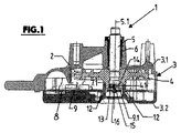
図1〜図4において、1は電動補助駆動装置の伝動装置を示し、電動補助駆動装置は、この伝動装置1のほかに、図に表わされていない電動機を備えている。図1に破線で示してあるロータシャフト2が、伝動装置ケース3内に入り込んでおり、ウォームとして形成されたロータシャフトの一部が、伝動装置ケース3の内部に配置され、ウォーム歯車として形成されている歯車4と一緒に作動する。
1 to 4, reference numeral 1 denotes a transmission device of the electric auxiliary drive device, and the electric auxiliary drive device includes an electric motor (not shown) in addition to the transmission device 1. A
伝動装置ケース3は、図示の実施形態においては、2つの部分からなり、図示しない電動機、より具体的には、電動機のハウジングがフランジで固定されるケース要素3.1と、伝動装置ケース3が閉じられるとき、ケース要素3.1上に配置されて、例えば、ねじで固定することにより、このケース要素3.1に適切に結合されている、ふた状のケース要素3.2とから成っている。
In the illustrated embodiment, the
伝動装置1、より具体的には、電動補助駆動装置の出力シャフトを形成し、伝動装置ケース3、より具体的には、ケース要素3.1から突き出したシャフト端を有し、このシャフト端の領域において、ケース要素3.1内の軸受け6によって回転可能に保持されているシャフト5に、歯車4が嵌合されている。
The transmission device 1, more specifically, the output shaft of the electric auxiliary drive device, has a shaft end protruding from the
シャフト5の他端の領域には、別の軸受けが設けられ、軸方向および半径方向に支持されている。より具体的に言うと、ふた状のケース要素3.2の底と一体に成型されており、その底の内側表面から、伝動装置ケース3の内部に突き出した、さや状またはリング状の軸受け素子7によって支持されている。シャフト軸5.1と同軸に配置された、この軸受け素子7内において、歯車4が、シャフト軸5.1を同心的に取り囲んで、リング形状または円筒形状の軸受け面を形成している半径方向の支持部に、ハブ状部分4.1ではまり込んでいる。さらに、歯車4は、軸受け素子7の前面7.1に接して、軸方向に支持されている。
Another bearing is provided in the region of the other end of the
電動補助駆動装置、より具体的には、図示しない電動機を制御するために、さらに、電子的な、マイクロプロセッサを使った制御デバイス8(制御モジュール)が、伝動装置ケース内に収容されている。より具体的に言うと、回路基板またはプリント基板9、その他のものを用いて、制御デバイス8の構成部品10が配置されている。制御デバイス8、より具体的には、そのプリント基板9は、ふた状のケース要素3.2の内側表面に固定されている。
In order to control the electric auxiliary drive device, more specifically, an electric motor (not shown), an electronic control device 8 (control module) using a microprocessor is housed in the transmission case. More specifically, the
より具体的に言うと、伝動装置ケース3が閉じているときには、プリント基板9の表面は、シャフト軸5.1と直交する平面になる向きに置かれており、プリント基板9は、伝動装置ケース3が閉じた状態で、ふた状のケース要素3.2の端がケース要素3.1の開口端に接続している場所に、ほぼ位置するように固定されている。
More specifically, when the
さや状の軸受け素子7は、ケース要素3.2の底から隔たった、その自由端から始まる複数の切り込みを縦方向に入れられており、その結果、相応する切り込み11によって、軸受け素子7のセグメント状の構造が形成されている。より具体的に言えば、図示の実施形態においては、3つの切り込み11によって、3つのリング状セグメント7.2を持つ構造体が形成されている。
The sheath-
プリント基板9には、リング状セグメント7.2に対応する開口12が設けられており、したがって、プリント基板9を、ケース要素3.2の内部に固定する際に、開口12を用いて軸受け素子7に、より詳細には、リング状セグメント7.2に押して嵌め込むことができ、そのため、リング状セグメント7.2が、プリント基板9の、ケース要素3.1に面する側の上方に突き出る。
The printed
さらにプリント基板9は、軸受け素子7の内部に、すなわち、軸受け素子の内部7.3に、プリント基板の一部9.1を有している。切り込み11は、それらが、軸受け素子7の自由端から始まって、軸受け素子の全高にわたらずに、歯車4から見て遠い側の、プリント基板9の下面の高さに、ケース要素3.2の底から間隔を置いて延びている。そのため、プリント基板は、切り込み11の領域内に支持されるように、作られているのが好ましい。
Furthermore, the printed
軸受け6から隔たったシャフト5のシャフト端において、その前面に、永久磁石13が配置されている。この永久磁石13は、図3に示す実施形態においては、円盤状の永久磁石13であり、円柱の半分13.1がS極として、他の半分13.2がN極となるように、磁化されている。したがって、分極の異なる、最も高い磁界強度を持つ2つの領域が、円柱形状の永久磁石13の軸に関して、直径方向に互いに逆側に位置する。
A
図示の実施形態においては、永久磁石13は、適切な円柱状の開口14(図1においては、下端が、プリント基板9に向かって開口し、上端が、シャフト5の前面によって限定されている)内に収容されている。
In the illustrated embodiment, the
シャフト軸5.1と同軸に配置された軸を持つ永久磁石13に対向して、2つの磁気センサ15および16が、プリント基板の一部9.1に配置されている、より具体的に言うと、図示の実施形態においては、永久磁石13に面しているプリント基板9の上面上に、磁気センサ15が配置されており、永久磁石13から遠い側にある、プリント基板9の下面上に、磁気センサ16が配置されている。
More specifically, two
伝動装置ケース3の外部に対して閉じた、リング状の軸受け素子7の内部7.3に収容されている両磁気センサ15および16は、それぞれ、磁界(多くの観点の中でも、とりわけ、磁界強度または磁界の方向)または磁界の変化に依存して、少なくとも1つの電気的なセンサ信号を送出する。磁気センサ15および16は、例えば、電気抵抗値が磁界に依存して変化する磁気抵抗センサ、または、ホールセンサである。
Both
シャフト軸5.1が、それぞれの磁気センサ15および16と、そのセンサ中心点において交差し、磁気センサ15および16が、それらのセンサ軸をシャフト軸5.1に対して半径方向になる向きとされ、さらに、90°未満の、あらかじめ定められた角度範囲だけ、シャフト軸5.1の周りに、互いに対して角度をなすように、磁気センサは、プリント基板の一部9.1上に配置されている。
A shaft axis 5.1 intersects each
シャフト5および歯車4が回転すると、永久磁石13も一緒に運動し、その結果、両磁気センサ15および16は、磁界の回転に起因して、より詳細には、センサ軸に対して磁界の方向が変化することに起因して、シャフト5の回転に応じて、それぞれ、例えば、連続した正弦波または余弦波(磁気センサ15および16のセンサ信号は、それらのセンサ軸の相異なる向きに応じて位相変位する)を示す、少なくとも1つのセンサ信号を送出する。
When the
磁気センサ15および16によって送出されるセンサ信号、または、それらの組み合わせに基づいて、シャフト5の絶対角度位置、または、回転位置を決定することが可能である。さらに、制御デバイス8は、センサ信号に基づいて、例えば、それらのセンサ信号の時間的変化または極性または位相関係から、位置だけではなくて、シャフト5の回転速度または回転方向を決定することができる。
Based on the sensor signals sent by the
上記の構造を用いると、軸受け素子7によって、シャフト5、より詳細には、歯車4に対する支持体を加えているにもかかわらず、センサ機構の素子を、シャフト軸5.1と同軸に、より詳細には、シャフト軸5.1上に中心を置くように組み込み、それによって、センサ信号として、連続した正弦波または余弦波であるセンサ信号、または、少なくとも最適に近似されたセンサ信号を獲得することが可能であり、それによって、シャフト5のそれぞれの角度位置と、さらに、このシャフトのそれぞれの絶対角度位置を、制御デバイス8を用いて高精度に決定することができる。
With the above structure, the element of the sensor mechanism is more coaxial with the shaft shaft 5.1 in spite of the addition of a support for the
制御デバイス8、および、永久磁石13および磁気センサ15、16によって形成されたセンサ機構によって、電動補助駆動装置、より詳細には、この電動補助駆動装置の電動機の、例えばシャフト5の反転回転運動のための、正確な制御が可能である。
By means of the
さらに、シャフト5の角度位置を、他の制御目的および監視目的のために、例えば、電動補助駆動装置と他の機能要素との同期動作のために用いることもでき、そのとき、センサ機構によって決定された絶対角度を、他の機能素子またはデバイス、および他の制御素子またはデバイスに転送することが、例えばバスシステムを介して可能である。
Furthermore, the angular position of the
電動補助駆動装置、より詳細には、伝動装置1が、例えば座席位置調整、サンルーフまたは自動車の窓の開閉などのためのアクチュエータの一部である場合には、センサ機構、より詳細には、センサ機構によって送出されるセンサ信号を、その時々のアクチュエータの軌跡または、運動の許容範囲の監視、または制御などに用いることもできる。 A motorized auxiliary drive device, more particularly a transmission mechanism 1, for example when it is part of an actuator for seat position adjustment, sunroof or opening / closing of a car window, etc. The sensor signal sent by the mechanism can be used for monitoring or controlling the trajectory of the actuator or the allowable range of motion.
さらに、当然ながら、センサ機構によって送出されたセンサ信号を、シャフト5の回転速度または回転方向の決定のために用いることもできる。
Furthermore, it goes without saying that the sensor signal sent by the sensor mechanism can also be used for determining the rotational speed or direction of the
図5は、伝動装置1aのさらなる一実施形態を、図1と同様の表現で示しており、伝動装置1aは、基本的に、歯車4に対応する歯車4aが、軸受け素子7、より詳細には、対応するリング状セグメント7.2の内側表面および外側表面の両方で支持されているということ以外は、伝動装置1と異なっていない。そのため、歯車4aは、そのハブ状部分4a.1に、ハブ状部分4a.1の前面に開口し、かつ、シャフト軸5.1を同心的に囲むリング状の溝17を設けられており、軸受け素子7、より詳細には、軸受け素子7のリング状の部分は、プリント基板9の上方に、その長さの一部だけ突き出している。
FIG. 5 shows a further embodiment of the
以上本発明を、実施例に基づいて説明した。変更例および変形例が、本発明の思想から逸脱することなく可能であることは言うまでもない。 In the above, this invention was demonstrated based on the Example. It goes without saying that modifications and variations are possible without departing from the spirit of the invention.
したがって、例えば、永久磁石13ではなくて、磁気センサ15および16の領域に磁界を発生させ、シャフト5の回転運動とともに回転させ、かつ磁気センサ15および16に、その回転に応じて異なるセンサ信号を発生する、別の磁石構成を設けることも可能である。
Therefore, for example, a magnetic field is generated not in the
上述において、センサ機構は、2つの磁気センサ15および16を持つと仮定してある。しかしながら、原理的には、ただ1つの磁気センサ15または16だけを備えることも、また、さらには、2つ以上の磁気センサの機能を備えるセンサ部品を用いることも可能である。
In the above, it is assumed that the sensor mechanism has two
1、1a 伝動装置
2 ロータシャフト
3 伝動装置ケース
3.1、3.2 ケース要素
4、4a 歯車
4.1、4a.1 ハブ状部分
5 シャフト
5.1 シャフト軸
6 軸受け
7 軸受け装置
7.1 前面
7.2 リング状セグメント
7.3 内部
8 制御デバイス
9 プリント基板
9.1 プリント基板の一部
10 構成部品
11 切り込み
12、14 開口
13 永久磁石
13.1、13.2 円柱の半分
15、16 磁気センサ
17 リング状の溝
1,
Claims (16)
少なくとも1つの永久磁石(13)により形成され、前記歯車(4)又は出力シャフト(5)とともに回転する信号発信体又は永久磁石配置、並びに少なくとも1つの磁気センサ(15, 16)を有し、前記少なくとも1つの磁気センサ(15, 16)が、前記信号発信体又は永久磁石配置と協働して、前記歯車(4)及び出力シャフト(5)の角度位置、又はその変化を記録するようになっているセンサ機構と
を備える、車両用のワイパ駆動装置または車両要素の調整駆動装置用の電動式の補助駆動装置であって、
前記歯車(4)の開口部(14)には、前記出力シャフト(5)が途中まで挿入されることによって、前記出力シャフト(5)の端面と前記開口部(14)の壁面とで構成される凹部が形成されており、前記永久磁石(13)は、前記凹部に収容されているとともに、軸受け構成(7)内に定置されており、前記少なくとも1つの磁気センサ(15, 16)は、前記軸受け構成(7)内で、制御モジュール(8)の回路基板又はプリント基板(9)の上において、シャフト軸(5.1)の方向に、前記永久磁石(13)に対向するように配置されており、
前記軸受け構成は、伝動装置ケース(3)のケース要素(3.2)から前記伝動装置の内部に突き出して、少なくとも1つの軸受け面を形成し、かつ、少なくとも前記永久磁石(13)、及び前記少なくとも1つの磁気センサ(15, 16)を受容するためのカットアウトを備えている軸受け素子(7)から成っており、かつ、前記少なくとも1つの磁気センサ(15, 16)を支持している、前記回路基板又はプリント基板(9)の一部(9.1)が、前記軸受け素子(7)の前記カットアウト内に位置するように、前記軸受け素子(7)が、前記回路基板又はプリント基板(9)の開口(12)を貫通している
ことを特徴とする補助駆動装置。 A gear (4) and an output shaft (5), one end of the output shaft (5) is fitted in the opening (14) of the gear (4), and transmits the drive of the motor A transmission (1),
A signal emitter or permanent magnet arrangement formed by at least one permanent magnet (13) and rotating with said gear (4) or output shaft (5), and at least one magnetic sensor (15, 16), At least one magnetic sensor (15, 16), in cooperation with the signal emitter or permanent magnet arrangement, records the angular position of the gear (4) and the output shaft (5), or changes thereof. An electric auxiliary drive device for a vehicle wiper drive device or a vehicle element adjustment drive device, comprising:
The output shaft (5) is inserted halfway into the opening (14) of the gear (4), and is configured by an end surface of the output shaft (5) and a wall surface of the opening (14). The permanent magnet (13) is housed in the recess and is placed in a bearing configuration (7), and the at least one magnetic sensor (15, 16) is In the bearing configuration (7), on the circuit board or printed circuit board (9) of the control module (8), it is arranged to face the permanent magnet (13) in the direction of the shaft axis (5.1). And
The bearing arrangement projects from the case element (3.2) of the transmission case (3) into the transmission to form at least one bearing surface, and at least the permanent magnet (13) and the at least one Said circuit comprising a bearing element (7) with a cut-out for receiving one magnetic sensor (15, 16) and supporting said at least one magnetic sensor (15, 16) The bearing element (7) is positioned on the circuit board or printed board (9) so that a part (9.1) of the board or printed board (9) is located in the cutout of the bearing element (7). An auxiliary drive device characterized by passing through the opening (12) .
Applications Claiming Priority (3)
| Application Number | Priority Date | Filing Date | Title |
|---|---|---|---|
| DE102005040647.5 | 2005-08-27 | ||
| DE102005040647A DE102005040647A1 (en) | 2005-08-27 | 2005-08-27 | Electromotive auxiliary drive e.g. windshield wiper drive, for e.g. road vehicle, has permanent magnet provided at shaft extension or at gearing unit, and magnetic sensors provided within bearing arrangement toward shaft axis |
| PCT/IB2006/003679 WO2007036810A2 (en) | 2005-08-27 | 2006-08-25 | Electromotive servodrive for vehicles |
Publications (2)
| Publication Number | Publication Date |
|---|---|
| JP2009506337A JP2009506337A (en) | 2009-02-12 |
| JP5296541B2 true JP5296541B2 (en) | 2013-09-25 |
Family
ID=37735364
Family Applications (1)
| Application Number | Title | Priority Date | Filing Date |
|---|---|---|---|
| JP2008528603A Expired - Fee Related JP5296541B2 (en) | 2005-08-27 | 2006-08-25 | Electric auxiliary drive device for vehicle |
Country Status (13)
| Country | Link |
|---|---|
| US (1) | US7808196B2 (en) |
| EP (1) | EP1917167B9 (en) |
| JP (1) | JP5296541B2 (en) |
| KR (1) | KR20080055814A (en) |
| CN (1) | CN101296824B (en) |
| AT (1) | ATE503664T1 (en) |
| BR (1) | BRPI0615392A2 (en) |
| DE (2) | DE102005040647A1 (en) |
| ES (1) | ES2363441T3 (en) |
| MX (1) | MX2008002730A (en) |
| RU (1) | RU2008111636A (en) |
| TW (1) | TW200726960A (en) |
| WO (1) | WO2007036810A2 (en) |
Families Citing this family (24)
| Publication number | Priority date | Publication date | Assignee | Title |
|---|---|---|---|---|
| DE102007016133A1 (en) * | 2007-03-29 | 2008-10-02 | Robert Bosch Gmbh | Measuring device for non-contact detection of a rotation angle with arranged in a recess of the magnet magnetically sensitive element |
| US8857464B2 (en) * | 2008-01-30 | 2014-10-14 | Flowserve Management Company | Valve actuators having magnetic angle sensors |
| DE102008024357A1 (en) * | 2008-05-20 | 2009-11-26 | Valeo Systèmes d'Essuyage | Electric motor wiper drive |
| DE102008029463A1 (en) | 2008-06-20 | 2009-12-24 | Valeo Systèmes d'Essuyage | Electromotive auxiliary drive e.g. windscreen wiper drive, for vehicle, has bearing comprising projection extending into annular groove that is provided at gear wheel and concentrically enclosing shaft axis |
| DE102008042246A1 (en) | 2008-09-22 | 2010-04-01 | Robert Bosch Gmbh | windshield wiper drive |
| US10320265B2 (en) | 2009-07-30 | 2019-06-11 | Mitsuba Corporation | Wiper motor |
| CN102474160B (en) | 2009-07-30 | 2014-11-12 | 株式会社美姿把 | Motor with speed reduction mechanism |
| DE102009047129A1 (en) * | 2009-11-25 | 2011-05-26 | Robert Bosch Gmbh | Drive unit and windshield wiper drive with a drive unit |
| JP5287787B2 (en) * | 2010-04-16 | 2013-09-11 | 株式会社デンソー | Electric device |
| JP2012018150A (en) * | 2010-07-10 | 2012-01-26 | Tamagawa Seiki Co Ltd | Motor magnetic pole detection system and hall sensor |
| CN103180092B (en) * | 2010-10-26 | 2016-01-13 | 村田机械株式会社 | Conveyer |
| US9525322B2 (en) * | 2011-11-22 | 2016-12-20 | Mitsuba Corporation | Wiper motor |
| DE102012100829A1 (en) * | 2012-02-01 | 2013-08-01 | Valeo Systèmes d'Essuyage | Device for detecting the angular position of a shaft of an electric motor and windscreen wiper motor with a device for detecting the angular position |
| DE102012216366A1 (en) * | 2012-09-14 | 2014-03-20 | Aktiebolaget Skf | Electromechanical actuator |
| DE102013107144A1 (en) * | 2013-07-08 | 2015-01-22 | Valeo Systèmes d'Essuyage | Housing element for a wiper motor, method for producing a housing element and wiper motor |
| DE102014100540A1 (en) * | 2014-01-17 | 2015-07-23 | Trinamic Motion Control Gmbh & Co. Kg | Electric motor with rotary position sensor |
| DE102014218716A1 (en) * | 2014-09-17 | 2016-03-17 | Continental Teves Ag & Co. Ohg | Encoder shaft for level sensor pressed into the housing |
| DE102014118041B4 (en) * | 2014-12-05 | 2021-10-07 | Pwb Encoders Gmbh | Rotary encoder and method for mounting it on an assembly |
| DE102015201411A1 (en) * | 2015-01-28 | 2016-07-28 | Robert Bosch Gmbh | Motor-pump unit for a brake system |
| DE102015213828A1 (en) * | 2015-07-22 | 2017-01-26 | Mahle International Gmbh | Assembly for an adjusting device, in particular an exhaust gas turbocharger, and method for producing such an assembly |
| JP6555367B2 (en) * | 2018-02-05 | 2019-08-07 | 株式会社デンソー | Wiper device |
| DE102018210130A1 (en) | 2018-06-21 | 2019-12-24 | Mahle International Gmbh | Actuator and a method for manufacturing the actuator |
| DE102020206966A1 (en) | 2020-06-04 | 2021-12-09 | Robert Bosch Gesellschaft mit beschränkter Haftung | Wiper device and gear unit |
| US11722036B2 (en) | 2021-06-14 | 2023-08-08 | Commercial Vehicle Group, Inc. | Wiper motors and methods of manufacture and use thereof |
Family Cites Families (53)
| Publication number | Priority date | Publication date | Assignee | Title |
|---|---|---|---|---|
| JPS6044802A (en) * | 1983-08-23 | 1985-03-11 | Yokogawa Hokushin Electric Corp | Angle converter |
| JPS6074013U (en) * | 1983-10-28 | 1985-05-24 | 株式会社安川電機 | detection device |
| DE3446761C2 (en) * | 1984-12-21 | 1986-10-30 | SWF Auto-Electric GmbH, 7120 Bietigheim-Bissingen | Windshield wiper systems, in particular for motor vehicles |
| DE3639208A1 (en) * | 1986-11-15 | 1988-05-19 | Bosch Gmbh Robert | MAGNETORESISTIVE SENSOR FOR DELIVERING ELECTRICAL SIGNALS |
| DE3878240D1 (en) | 1988-09-21 | 1993-03-18 | Siemens Ag | ELECTRIC MOTOR DRIVE, IN PARTICULAR ADJUSTMENT DRIVE FOR A MOTOR VEHICLE. |
| JPH0723612Y2 (en) * | 1989-11-07 | 1995-05-31 | 三菱重工業株式会社 | Split bearing |
| JPH0420812A (en) * | 1990-05-15 | 1992-01-24 | Tokai Rika Co Ltd | Rotation angle detector |
| JPH04130216A (en) * | 1990-09-21 | 1992-05-01 | Murata Mfg Co Ltd | Two-phase magnetic type angle sensor |
| JP2546096B2 (en) * | 1991-12-04 | 1996-10-23 | 日本電装株式会社 | Position detection device |
| JP3206204B2 (en) * | 1992-05-22 | 2001-09-10 | 株式会社デンソー | Throttle position sensor |
| JP3043529B2 (en) * | 1992-10-08 | 2000-05-22 | 愛三工業株式会社 | Rotation angle sensor |
| JP3090449B2 (en) * | 1993-06-15 | 2000-09-18 | アスモ株式会社 | Motor rotation position detector |
| EP0680600B1 (en) * | 1993-11-20 | 1999-01-27 | AB Elektronik GmbH | Adjusting device |
| JP3200281B2 (en) * | 1994-03-29 | 2001-08-20 | 株式会社ゼクセルヴァレオクライメートコントロール | Brushless motor |
| WO1996016316A1 (en) * | 1994-11-22 | 1996-05-30 | Robert Bosch Gmbh | Arrangement for the contactless determination of the angle of rotation of a rotatable component |
| JPH08178612A (en) * | 1994-12-22 | 1996-07-12 | Zexel Corp | Rotation angle detector |
| JPH08248056A (en) * | 1995-03-08 | 1996-09-27 | Toshiba Corp | Rotation detector |
| US5844338A (en) * | 1995-12-18 | 1998-12-01 | Siemens Electric Limited | Slim-line brushless motor with inside mounted single bearing |
| US5675206A (en) * | 1995-12-18 | 1997-10-07 | Siemens Electric Limited | Slim-line brushless motor |
| DE19548385C2 (en) * | 1995-12-22 | 1998-11-12 | Siemens Ag | Method for determining the angular position of an axis of rotation of an object by a computer |
| JP3433054B2 (en) * | 1997-07-04 | 2003-08-04 | 株式会社日立ユニシアオートモティブ | Rotation angle detector |
| DE19754843A1 (en) * | 1997-12-10 | 1999-06-24 | Bosch Gmbh Robert | Drive device for a part of a vehicle that can be moved between end positions and method for its production |
| JP3474096B2 (en) * | 1998-02-09 | 2003-12-08 | 株式会社日立ユニシアオートモティブ | Rotation angle detector |
| JP3052063U (en) * | 1998-03-06 | 1998-09-11 | 船井電機株式会社 | Electric motor |
| EP0984121A3 (en) * | 1998-09-01 | 2003-01-29 | Siemens Aktiengesellschaft | Actuator |
| DE19848081A1 (en) | 1998-09-01 | 2000-03-02 | Mannesmann Vdo Ag | Drive device with an actuator |
| JP3632038B2 (en) * | 1998-09-19 | 2005-03-23 | 株式会社日立製作所 | Rotation angle detector |
| US6483296B1 (en) * | 1999-06-17 | 2002-11-19 | Denso Corporation | Angular position detection apparatus |
| JP2001124508A (en) * | 1999-10-22 | 2001-05-11 | Aisan Ind Co Ltd | Rotary position sensor |
| JP3843969B2 (en) * | 1999-11-01 | 2006-11-08 | 株式会社デンソー | Rotation angle detector |
| JP3491587B2 (en) * | 1999-12-21 | 2004-01-26 | 株式会社デンソー | Fail mode adjustment method of rotation angle detection sensor |
| DE10007968C1 (en) * | 2000-02-22 | 2001-08-09 | Daimler Chrysler Ag | Mechanical shaft with integrated magnet arrangement |
| JP2002022406A (en) * | 2000-07-11 | 2002-01-23 | Yazaki Corp | Rotation angle sensor |
| JP3699887B2 (en) * | 2000-07-25 | 2005-09-28 | アルプス電気株式会社 | Rotation type sensor |
| FR2816047B1 (en) * | 2000-11-02 | 2003-02-07 | Skf Ab | INSTRUMENTED ROLLING BEARING DEVICE, IN PARTICULAR FOR CONTROL WHEEL |
| JP2002156247A (en) * | 2000-11-16 | 2002-05-31 | Teikoku Tsushin Kogyo Co Ltd | Rotation angle sensor |
| JP2002174532A (en) * | 2000-12-07 | 2002-06-21 | Sensatec Co Ltd | Contactless variable voltage device |
| DE10113678A1 (en) * | 2001-03-21 | 2002-10-02 | Bosch Gmbh Robert | Wiper system with two wipers |
| JP2002323345A (en) * | 2001-04-25 | 2002-11-08 | Kayaba Ind Co Ltd | Rotation angle sensor |
| DE10133631A1 (en) * | 2001-07-11 | 2003-01-30 | Siemens Ag | Method for contactless detection of the position of a throttle valve shaft of a throttle valve connector and throttle valve connector |
| JP3941467B2 (en) * | 2001-11-14 | 2007-07-04 | アイシン精機株式会社 | Electronic component connection structure |
| JP3799270B2 (en) * | 2001-12-21 | 2006-07-19 | 株式会社日立製作所 | Control device for switching the driving state of an automobile |
| DE10201141B4 (en) * | 2002-01-15 | 2009-10-15 | Pierburg Gmbh | Stellgetriebe with means for determining the deviation from a predetermined starting position |
| FR2837755B1 (en) * | 2002-03-28 | 2004-08-27 | Valeo Equip Electr Moteur | MOUNTING OF ROTATING ELECTRIC MACHINE FOR MOTOR VEHICLE |
| DE10228663A1 (en) * | 2002-06-27 | 2004-01-22 | Philips Intellectual Property & Standards Gmbh | Arrangement for determining the position of a body |
| JP4230249B2 (en) * | 2003-02-28 | 2009-02-25 | アイチ・マイクロ・インテリジェント株式会社 | Throttle opening detector |
| JP2004271451A (en) * | 2003-03-11 | 2004-09-30 | Hitachi Unisia Automotive Ltd | Rotational angle detector |
| JP2004279265A (en) * | 2003-03-17 | 2004-10-07 | Yazaki Corp | Rudder angle sensor |
| DE10349556A1 (en) | 2003-10-22 | 2005-06-02 | Micronas Gmbh | Transmitter device with an angle sensor |
| JP4045230B2 (en) * | 2003-11-04 | 2008-02-13 | 三菱電機株式会社 | Non-contact rotation angle detector |
| JP2005156264A (en) * | 2003-11-21 | 2005-06-16 | Asahi Kasei Electronics Co Ltd | Rotation angle sensor |
| DE10360042A1 (en) * | 2003-12-18 | 2005-07-21 | Valeo Motoren Und Aktuatoren Gmbh | Position-detection method for determining an absolute relative position for a rotatable shaft uses sensors fitted in relation to the shaft to detect relative positions |
| DE102007016133A1 (en) * | 2007-03-29 | 2008-10-02 | Robert Bosch Gmbh | Measuring device for non-contact detection of a rotation angle with arranged in a recess of the magnet magnetically sensitive element |
-
2005
- 2005-08-27 DE DE102005040647A patent/DE102005040647A1/en not_active Withdrawn
-
2006
- 2006-08-21 TW TW095130658A patent/TW200726960A/en unknown
- 2006-08-25 CN CN2006800397946A patent/CN101296824B/en not_active Expired - Fee Related
- 2006-08-25 RU RU2008111636/11A patent/RU2008111636A/en not_active Application Discontinuation
- 2006-08-25 KR KR1020087005927A patent/KR20080055814A/en not_active Application Discontinuation
- 2006-08-25 US US12/065,080 patent/US7808196B2/en not_active Expired - Fee Related
- 2006-08-25 ES ES06831754T patent/ES2363441T3/en active Active
- 2006-08-25 AT AT06831754T patent/ATE503664T1/en active
- 2006-08-25 JP JP2008528603A patent/JP5296541B2/en not_active Expired - Fee Related
- 2006-08-25 DE DE502006009218T patent/DE502006009218D1/en active Active
- 2006-08-25 MX MX2008002730A patent/MX2008002730A/en not_active Application Discontinuation
- 2006-08-25 EP EP06831754A patent/EP1917167B9/en not_active Not-in-force
- 2006-08-25 BR BRPI0615392-5A patent/BRPI0615392A2/en not_active Application Discontinuation
- 2006-08-25 WO PCT/IB2006/003679 patent/WO2007036810A2/en active Application Filing
Also Published As
| Publication number | Publication date |
|---|---|
| DE102005040647A1 (en) | 2007-03-08 |
| EP1917167B1 (en) | 2011-03-30 |
| JP2009506337A (en) | 2009-02-12 |
| ES2363441T3 (en) | 2011-08-04 |
| MX2008002730A (en) | 2008-03-26 |
| CN101296824A (en) | 2008-10-29 |
| US20080246374A1 (en) | 2008-10-09 |
| CN101296824B (en) | 2010-06-09 |
| EP1917167B9 (en) | 2011-09-07 |
| KR20080055814A (en) | 2008-06-19 |
| TW200726960A (en) | 2007-07-16 |
| WO2007036810A2 (en) | 2007-04-05 |
| BRPI0615392A2 (en) | 2012-12-04 |
| RU2008111636A (en) | 2009-10-10 |
| EP1917167A2 (en) | 2008-05-07 |
| US7808196B2 (en) | 2010-10-05 |
| DE502006009218D1 (en) | 2011-05-12 |
| WO2007036810A3 (en) | 2007-10-04 |
| ATE503664T1 (en) | 2011-04-15 |
Similar Documents
| Publication | Publication Date | Title |
|---|---|---|
| JP5296541B2 (en) | Electric auxiliary drive device for vehicle | |
| US9097559B2 (en) | Non-contact multi-turn absolute position magnetic sensor comprising a through-shaft | |
| US10161519B2 (en) | Electronic parking lock apparatus | |
| JP2009192081A (en) | Drive device | |
| US8164327B2 (en) | Steering angle sensor | |
| EP3351906B1 (en) | Door position detection device for electric door opener | |
| KR20070110353A (en) | Method and device for determining the rotational angle of a rotatable element in a non-contact manner | |
| US8573086B2 (en) | Lever operation device | |
| JP2010520458A (en) | Linear position sensor | |
| JP2012244851A (en) | Rotation detection device and motor | |
| CN107206969B (en) | Drive unit for a wiper system | |
| JP3645508B2 (en) | motor | |
| JP2003214845A (en) | Device for determining steering angle of car steering wheel | |
| CN210153180U (en) | High-precision shaft system with multi-position locking mechanism | |
| KR101490952B1 (en) | Apparatus of detecting position of rotating member and system of operating wiper | |
| US8334470B2 (en) | Lever operation device | |
| KR20180027493A (en) | Sensor arrangement having a modular structure | |
| KR100622125B1 (en) | Wheel steering sensor assembly | |
| JP2000505922A (en) | Latch switching mechanism | |
| EP3708465B1 (en) | Vehicle with steering angle sensor | |
| JP2954729B2 (en) | Wiper drive | |
| JP4690710B2 (en) | Electric motor with reduction mechanism | |
| JPH0545508U (en) | Rotary encoder | |
| KR940007921B1 (en) | Electric motor type starter with rpm sensor | |
| JP2002340510A (en) | Detector for rotation angle |
Legal Events
| Date | Code | Title | Description |
|---|---|---|---|
| A621 | Written request for application examination |
Free format text: JAPANESE INTERMEDIATE CODE: A621 Effective date: 20090722 |
|
| A977 | Report on retrieval |
Free format text: JAPANESE INTERMEDIATE CODE: A971007 Effective date: 20110608 |
|
| A131 | Notification of reasons for refusal |
Free format text: JAPANESE INTERMEDIATE CODE: A131 Effective date: 20110621 |
|
| A601 | Written request for extension of time |
Free format text: JAPANESE INTERMEDIATE CODE: A601 Effective date: 20110914 |
|
| A602 | Written permission of extension of time |
Free format text: JAPANESE INTERMEDIATE CODE: A602 Effective date: 20110922 |
|
| A521 | Request for written amendment filed |
Free format text: JAPANESE INTERMEDIATE CODE: A523 Effective date: 20111220 |
|
| A131 | Notification of reasons for refusal |
Free format text: JAPANESE INTERMEDIATE CODE: A131 Effective date: 20120904 |
|
| A601 | Written request for extension of time |
Free format text: JAPANESE INTERMEDIATE CODE: A601 Effective date: 20121203 |
|
| A602 | Written permission of extension of time |
Free format text: JAPANESE INTERMEDIATE CODE: A602 Effective date: 20121210 |
|
| A521 | Request for written amendment filed |
Free format text: JAPANESE INTERMEDIATE CODE: A523 Effective date: 20121227 |
|
| TRDD | Decision of grant or rejection written | ||
| A01 | Written decision to grant a patent or to grant a registration (utility model) |
Free format text: JAPANESE INTERMEDIATE CODE: A01 Effective date: 20130514 |
|
| A61 | First payment of annual fees (during grant procedure) |
Free format text: JAPANESE INTERMEDIATE CODE: A61 Effective date: 20130613 |
|
| R150 | Certificate of patent or registration of utility model |
Ref document number: 5296541 Country of ref document: JP Free format text: JAPANESE INTERMEDIATE CODE: R150 Free format text: JAPANESE INTERMEDIATE CODE: R150 |
|
| R250 | Receipt of annual fees |
Free format text: JAPANESE INTERMEDIATE CODE: R250 |
|
| R250 | Receipt of annual fees |
Free format text: JAPANESE INTERMEDIATE CODE: R250 |
|
| R250 | Receipt of annual fees |
Free format text: JAPANESE INTERMEDIATE CODE: R250 |
|
| R250 | Receipt of annual fees |
Free format text: JAPANESE INTERMEDIATE CODE: R250 |
|
| R250 | Receipt of annual fees |
Free format text: JAPANESE INTERMEDIATE CODE: R250 |
|
| LAPS | Cancellation because of no payment of annual fees |