JP5293922B2 - Game machine - Google Patents
Game machine Download PDFInfo
- Publication number
- JP5293922B2 JP5293922B2 JP2008000726A JP2008000726A JP5293922B2 JP 5293922 B2 JP5293922 B2 JP 5293922B2 JP 2008000726 A JP2008000726 A JP 2008000726A JP 2008000726 A JP2008000726 A JP 2008000726A JP 5293922 B2 JP5293922 B2 JP 5293922B2
- Authority
- JP
- Japan
- Prior art keywords
- shielding
- gaming machine
- shielding member
- board
- ball
- Prior art date
- Legal status (The legal status is an assumption and is not a legal conclusion. Google has not performed a legal analysis and makes no representation as to the accuracy of the status listed.)
- Active
Links
Images


Abstract
Description
本発明は、パチンコ機やスロットマシンに代表される遊技機に関するものである。 The present invention relates to gaming machines represented by pachinko machines and slot machines.
パチンコ機やスロットマシンなどの遊技機には、始動口への入球に基づいて行われる抽選の結果等を図柄として変動表示する可変表示装置を備えるものがあるが、この可変表示装置の表示画面の前方で遮蔽部材(シャッタ)が開閉する構成とし、これにより図柄の変動表示の一部または全部を一時的に覆って見えないようにする演出がなされるようにしたものもある。 Some gaming machines such as pachinko machines and slot machines are equipped with a variable display device that variably displays the result of a lottery performed based on the entrance to the starting port as a symbol. The display screen of this variable display device In some cases, the shield member (shutter) opens and closes in front of the screen so that a part or all of the symbol variation display is temporarily covered so as not to be seen.
このような遊技機としては、例えば、以下の文献に記載のものが挙げられる。
しかしながら、上記のような遊技機においては、遮蔽部材を閉じた状態では、該遮蔽部材は言うまでもなく可変表示装置の表示画面を覆って視覚的に遮蔽する機能を果たすのであるが、開放した状態では、該遮蔽部材は特になんの機能を果たすこともなく、徒にスペースを占有して外観の面でも余計なものとなりやすい。 However, in the gaming machine as described above, when the shielding member is closed, the shielding member naturally functions to cover the display screen of the variable display device, but in the opened state. The shielding member does not perform any particular function, and easily occupies space and becomes excessive in appearance.
上記特許文献1によれば、遊技機の遮蔽部材を複数の部材に分割構成し、開放した状態では複数の部材を重ねるようにして両側に戸袋状に収納するようにし、さらに、この収納部分を、裏側から光を前方へ透過させることにより発光演出に利用するとの記載もあり、これによれば外観の面で一定の改善がなされるとも考えられるが、この構成では、遮蔽部材は収納部分の内部すなわち中間部分にあって光を透過させているに過ぎず、開放した状態の遮蔽部材自体の外観の向上といった点については特に考慮されているわけではない。
According to the above-mentioned
本発明は、かかる問題点に鑑みて案出されたものであり、開放した状態の遮蔽部材の外観を効果的に向上させることが可能な遊技機を提供することを目的とする。 The present invention has been devised in view of such problems, and an object thereof is to provide a gaming machine capable of effectively improving the appearance of an open shielding member.
本発明に係る遊技機は、上記目的を達成するために、
所定の契機に基づいて態様を変化させる可変部と、
前記可変部の少なくとも一部を遮蔽する遮蔽位置と当該遮蔽位置から退避した退避位置とに移動可能な遮蔽部材と、
前記遮蔽部材を駆動する駆動手段と、
を備える遊技機であって、
前記遮蔽部材は、前記退避位置から前記遮蔽位置へ移動する場合における先端面が、前記退避位置において前記移動方向よりも正面方向に近い方向を向いて露出されるようにし、
前記遮蔽部材の少なくとも一部に光透過性を有する光透過部が形成されていることを特徴とする。
Game machine according to the present invention, in order to achieve the above object,
A variable portion for changing the mode on the basis of Jo Tokoro of opportunity,
A shielding member that is movable to a shielding position that shields at least a part of the variable portion and a retreat position that is retracted from the shielding position ;
Driving means for drive the said shielding member,
A gaming machine comprising
The shield member is exposed such that a tip surface when moving from the retracted position to the shield position is directed in a direction closer to the front direction than the moving direction at the retracted position;
A light transmissive part having a light transmissive property is formed on at least a part of the shielding member .
本発明によれば、所定の契機に基づいて態様を変化させる可変部と、上記可変部の少なくとも一部を遮蔽する遮蔽位置と当該遮蔽位置から退避した退避位置とに移動可能な遮蔽部材と、上記遮蔽部材を開閉させるように駆動する駆動手段と、を備える遊技機において、上記遮蔽部材は、上記退避位置から上記遮蔽位置へ移動する場合における先端面が、上記退避位置において上記移動方向よりも正面方向に近い方向を向いて露出されるようにし、上記遮蔽部材の少なくとも一部に光透過性を有する光透過部が形成されている構成としたので、開放した状態の遮蔽部材の外観を効果的に向上させることが可能な遊技機が得られる。 According to the present invention, a variable portion that changes the mode based on a predetermined trigger, a shielding member that can move to a shielding position that shields at least a part of the variable portion, and a retreat position that is retracted from the shielding position , in a gaming machine and a driving means for moving driving so as to open and close the shielding member, the shielding member, the tip surface when moving from the retracted position to the shielding position, from the direction of movement in the retracted position also to be exposed toward the direction close to the front direction, the appearance of at least a portion since the configuration in which the light transmitting unit having light transmittance is formed, the state is released to open the shielding member in the shielding member A gaming machine capable of effectively improving the game machine is obtained.
本発明に係る遊技機は、手段1として、
所定の契機に基づいて態様を変化させる可変部と、
前記可変部の少なくとも一部を覆う遮蔽部材と、
前記遮蔽部材を開閉させるように駆動する駆動手段と、
を備える遊技機であって、
前記遮蔽部材に、該遮蔽部材の開動作にともなって向きを変え、該遮蔽部材が開いた状態となったときには閉じた状態のときより遊技機の前方を向く装飾演出部が形成されていることを特徴とする。
Game machine according to the present invention, as a
A variable unit that changes the mode based on a predetermined opportunity;
A shielding member covering at least a part of the variable portion;
Driving means for driving the shielding member to open and close;
A gaming machine comprising
A decorative effect portion is formed on the shielding member so that the orientation of the shielding member is changed in accordance with the opening operation of the shielding member, and when the shielding member is in an open state, the front is directed to the front of the gaming machine from the closed state. It is characterized by.
本発明において、「可変部」とは、始動口への入球など所定の契機に基づいて作動されることで大当たりの抽選結果に応じた情報などを表現するものであって、例えば図柄を変動表示する可変表示装置における表示面、可動部材の可動領域、LEDなどの発光手段の発光領域、などを含むものである。
また、「遮蔽部材」とは、可変部の少なくとも一部を覆うことができるものであって、例えば一端側を軸支することにより前方へ向けて扉状に開放可能に構成されたものであってもよい。この場合、軸とは反対側である開放端面を装飾演出部とすることができる。
また、「遮蔽部材を開閉させる」とは、遮蔽部材を前記表現部を露出させる開位置と遮蔽する閉位置とに移動させることを指す。
また、「装飾演出部」とは、例えば意匠を施すことや発光可能に構成すること等により装飾演出を行うようにしたものを意味し、閉じた状態のときに遊技機の前面側から視認できないものであってもよいし、視認できるものであってもよい。但し、閉じた状態よりも開いた状態のほうが遊技機の前方を向くものであるため、開いたときのほうが遊技機の前面側から視認し易くなるものである。
また、「遮蔽部材が開いた状態となったときには閉じた状態のときより遊技機の前方を向く装飾演出部」という場合の「前方」とは、例えば遊技機の遊技盤面に対し垂直に前側へ向かう方向だけでなく、前上方向、前下方向、前横方向等のように、上下左右にいくぶん傾斜しながら前側へ向かう方向を広く含意する。
In the present invention, the “variable part” represents information corresponding to the jackpot lottery result by being actuated based on a predetermined trigger such as a ball entering the start opening. It includes a display surface in a variable display device to display, a movable region of a movable member, a light emitting region of a light emitting means such as an LED, and the like.
In addition, the “shielding member” is a member that can cover at least a part of the variable portion, and is configured to be able to be opened forward like a door by pivotally supporting one end side, for example. May be. In this case, the open end surface on the side opposite to the shaft can be used as the decoration effect portion.
Further, “opening / closing the shielding member” refers to moving the shielding member between an open position where the expression unit is exposed and a closed position where the expression member is shielded.
Further, the “decoration effect part” means a decoration effect, for example, by applying a design or being configured to be capable of emitting light, and cannot be visually recognized from the front side of the gaming machine when closed. It may be a thing or a thing which can be visually recognized. However, since the opened state faces the front of the gaming machine rather than the closed state, the opened state is easier to see from the front side of the gaming machine.
In addition, “front” in the case of “decoration effect portion that faces the front of the gaming machine more than when it is closed when the shielding member is in the open state” means, for example, the front side perpendicular to the gaming board surface of the gaming machine It broadly implies not only the direction of heading but also the direction of heading to the front side while slightly tilting up and down, left and right, such as front-up direction, front-down direction, and front-side direction.
上記手段1に係る遊技機によれば、遮蔽部材が開いた状態となったときには閉じた状態のときより遊技機の前方を向く装飾演出部により、開放した状態の遮蔽部材において前方から視認される部位が装飾演出に有効に利用されるようになっている。また、該装飾演出部が、遮蔽部材が開いた状態となったときには閉じた状態のときより遊技機の前方を向くように、開動作にともなって向きを変える構成となっているので、該装飾演出部が遮蔽部材の開動作にともなって次第に前面に現れてくるような演出効果が得られる。
According to the gaming machine according to the
また、本発明にかかる遊技機は、手段2として、前記手段1の遊技機において、
遊技球が流下する遊技領域が前面側に形成された遊技盤を備え、
前記可変部は、前記遊技領域に設けられた始動口への遊技球の入球に基づいて図柄を変動表示する可変表示装置の表示面であることを特徴とする。
Further, the gaming machine according to the present invention is the gaming machine of the
A game board in which a game area in which a game ball flows down is formed on the front side;
The variable portion is a display surface of a variable display device that displays a variable pattern based on a game ball entering a start opening provided in the game area.
上記手段2に係る遊技機によれば、遮蔽部材が可変表示装置の表示面を覆うように開閉するため、表示面に対して図柄を変動表示しながら遊技者からはその表示が見えないようにすることができ、表示用データを増加させることなく表示面の態様を多様化させることができる。 According to the gaming machine according to the above means 2, the shielding member opens and closes so as to cover the display surface of the variable display device, so that the player cannot see the display while variably displaying the symbols on the display surface. The display surface can be diversified without increasing the display data.
また、本発明にかかる遊技機は、手段3として、
遊技球が流下する遊技領域が前面側に形成されるとともに、該遊技領域の所定箇所から裏面側へ貫通する貫通部(遊技盤30の貫通孔)が形成された遊技盤と、
枠状に形成され、その開口が前記遊技盤の前記貫通部に対応するように設けられるフレーム部材(センターフレーム43)と、
該フレーム部材の前記開口及び前記遊技盤の前記貫通部を介して前面側から視認可能に設けられ、所定の契機に基づいて態様を変化させる可変部と、
該可変部の前面側において、前記可変部の所定箇所を覆う遮蔽位置と、該遮蔽位置のときに覆われる前記可変部の所定箇所を露出させる露出位置と、に移動可能に設けられる遮蔽部材と、
該遮蔽部材を前記遮蔽位置と前記露出位置とに駆動させる駆動手段と、
前記遮蔽部材の態様を変化させる遮蔽部材態様変化手段(LED461など)と、
を備えた遊技機であって、
前記遮蔽部材は、前記遮蔽位置にあるときに前記可変部の前面側に位置する遮蔽部と、前記露出位置から前記遮蔽位置への移動方向に対する交差面を有する装飾演出部と、を備え、
前記装飾演出部は、前記遮蔽位置から前記露出位置へ向けて移動するのに際し、前記遮蔽位置よりも前記露出位置のほうが前方を向くように変化され、
前記遮蔽部材の前記露出位置を、正面視において前記装飾演出部の少なくとも一部が前記フレーム部材の開口内に位置した状態であって前記フレーム部材の内面、前記装飾演出部、及び前記可変部が連続した状態とし、前記遮蔽部材態様変更手段は、前記露出位置にある前記遮蔽部材の態様を変化させ得るように構成されていることを特徴とする。
In addition, the gaming machine according to the present invention has the means 3 as
A game board in which a game area in which a game ball flows down is formed on the front side, and a through portion (through hole of the game board 30) penetrating from a predetermined position of the game area to the back side is formed;
A frame member (center frame 43) that is formed in a frame shape and has an opening corresponding to the penetrating portion of the game board;
A variable portion that is provided so as to be visible from the front side through the opening of the frame member and the penetrating portion of the game board, and changes a mode based on a predetermined trigger;
A shielding member movably provided on a front surface side of the variable portion so as to be movable between a shielding position that covers a predetermined portion of the variable portion and an exposed position that exposes the predetermined portion of the variable portion that is covered at the shielding position; ,
Drive means for driving the shielding member to the shielding position and the exposed position;
Shielding member mode changing means (such as LED 461) for changing the mode of the shielding member;
A gaming machine equipped with
The shielding member includes a shielding part that is located on the front side of the variable part when in the shielding position, and a decorative effect part that has an intersecting surface with respect to the moving direction from the exposed position to the shielding position,
When the decoration effect unit moves from the shielding position toward the exposure position, the decoration position is changed so that the exposure position faces the front rather than the shielding position,
The exposed position of the shielding member is a state in which at least a part of the decoration effect part is located in the opening of the frame member in a front view, and the inner surface of the frame member, the decoration effect part, and the variable part are It is set as the continuous state, The said shielding member aspect change means is comprised so that the aspect of the said shielding member in the said exposure position can be changed.
本発明において、「遮蔽部材態様変化手段」とは、遮蔽手段の少なくとも一部の態様を変化させるものであって、例えば、遮蔽部材を照射することによって態様を変化させるLEDなどの発光手段や、遮蔽部材の外面の一部を構成し、可動されることによって遮蔽部材の態様を変化させる可動部材などが考えられる。 In the present invention, the “shielding member mode changing means” is for changing at least a part of the mode of the shielding means, for example, a light emitting means such as an LED that changes the mode by irradiating the shielding member, A movable member that constitutes a part of the outer surface of the shielding member and changes the aspect of the shielding member by being moved is considered.
上記手段3に係る遊技機によれば、手段1と同等の効果を奏するのに加えて、露出位置をフレーム部材の内面と装飾演出部と前記可変部とが連続した状態としながら遮蔽部材態様変更手段によって遮蔽部材の態様を変化させることができるため、可変部とその周辺箇所との連続した領域全体を使って変化のある装飾演出を行うことができる。
According to the gaming machine according to the means 3, in addition to having the same effect as the
また、本発明にかかる遊技機は、手段4として、前記手段2の遊技機において、
前記遮蔽部材をスライド可能に保持するレールを備え、
前記遮蔽部材が、前記レールに沿って所定の間隔をおいた少なくとも2点で該レールに保持され、
前記レールが、前記可変表示装置の表示面より前方にあって該表示面の少なくとも一部を覆う状態に前記遮蔽部材を保持する閉位置から、該閉位置からみて前記可変表示装置の表示面に対し所定の角度をなす方向に後退した位置にあって前記遮蔽部材を閉位置にあるときに比して後方に傾斜した状態に保持する開位置まで延びる形状を有することを特徴とする。
Further, the gaming machine according to the present invention is the gaming machine of the means 2 as the means 4,
A rail for slidably holding the shielding member;
The shielding member is held on the rail at at least two points spaced apart along the rail;
From the closed position where the rail is in front of the display surface of the variable display device and holds the shielding member in a state of covering at least a part of the display surface, from the closed position to the display surface of the variable display device It has a shape that extends to an open position that holds the shield member inclined backward as compared to when the shield member is in the closed position, in a position retracted in a direction that forms a predetermined angle.
上記手段4に係る遊技機によれば、遮蔽部材がレールに沿って閉位置から開位置までスライドし、後方に傾斜した状態となるようにして開放されるので、簡単な構成により、遮蔽部材が開いた状態となったときに装飾演出部が遊技機の前方を向くように該遮蔽部材の体勢を制御しながら、該遮蔽部材を閉位置から開位置まで容易に案内することができる。
また、開放した状態の遮蔽部材が後方に傾斜するようにして収納されるので、装飾演出部を除き遮蔽部材の大部分が前方から見え難い体勢、すなわち開放した状態の遮蔽部材における装飾演出部以外の外観上不要な部分が後方に隠れた体勢で収納されることとなり、したがって遮蔽部材における装飾演出部以外の部分により遊技機の外観が損なわれることも少ない。
さらにまた、開放した状態の遮蔽部材が可変表示装置の周囲のスペースを大きく占有することがなく、また部材を重ねたりすることなく収納されるため厚さが増大することもないし、逆に、重ねることなく収納されることで、遮蔽部材自体の厚さを大きめに設定することもできる。換言すれば、開放した状態の遮蔽部材を後方に傾斜させるようにして収納することで、可変表示装置の周囲方向に大きくスペースをとることなく、可変表示装置の周囲のスペースをできるだけ無駄なく有効に利用しながら遮蔽部材が収納されるという利点も得られる。また、可変表示装置の表示面の周囲に別の何らかの構成部材や部品が設置されている場合であっても、これらの構成部材や部品をよけるようにして遮蔽部材を開閉し収納することができる。
According to the gaming machine according to the means 4, the shielding member slides from the closed position to the open position along the rail and is opened so as to be inclined rearward. The shield member can be easily guided from the closed position to the open position while controlling the posture of the shield member so that the decoration effect section faces the front of the gaming machine when it is in the open state.
In addition, since the opened shielding member is stored so as to incline backward, the majority of the shielding member excluding the decoration effect portion is difficult to see from the front, that is, other than the decoration effect portion in the opened shielding member. Therefore, a portion unnecessary for the external appearance of the game machine is housed in a posture hidden behind, so that the appearance of the gaming machine is hardly damaged by a portion other than the decorative effect portion in the shielding member.
Furthermore, since the opened shielding member does not occupy a large space around the variable display device and is accommodated without overlapping the members, the thickness does not increase. By storing without any problem, the thickness of the shielding member itself can be set larger. In other words, by storing the opened shielding member so as to incline backward, the space around the variable display device is effectively used as much as possible without taking up a large space in the peripheral direction of the variable display device. There is also an advantage that the shielding member is accommodated while being used. Further, even when some other structural member or part is installed around the display surface of the variable display device, the shielding member can be opened / closed and stored so as to avoid the structural member or part. it can.
また、本発明にかかる遊技機は、手段5として、前記手段2または手段4の遊技機において、
前記駆動手段が、直線運動により動力を前記遮蔽部材に伝達する機構を備えることを特徴とする。
In addition, the gaming machine according to the present invention is the gaming machine of the means 2 or 4 as the means 5,
The drive means includes a mechanism for transmitting power to the shielding member by linear motion.
上記手段5に係る遊技機によれば、駆動手段の構成を簡単なものとすることができ、そのぶん占有スペースも少なく抑えることができる。特に、手段2の構成においては、遮蔽部材がレールに沿って閉位置と開位置との間で所定の軌跡上をスライド移動する構成となっているので、直線運動により動力を伝達することで、遮蔽部材をレールに案内させながら直線状でない軌跡上でも移動させることができる。 According to the gaming machine according to the means 5, the configuration of the driving means can be simplified, and the occupied space can be suppressed to a small extent. In particular, in the configuration of the means 2, the shielding member is configured to slide along a rail on a predetermined trajectory between the closed position and the open position, so by transmitting power by linear motion, The shielding member can be moved on a non-linear trajectory while being guided by the rail.
また、本発明にかかる遊技機は、手段6として、前記手段4または手段5の遊技機において、
前記遮蔽部材の少なくとも一部が、該遮蔽部材のスライド方向に沿って並置された複数の部材が回動可能に連結されて構成されていることを特徴とする。
Further, the gaming machine according to the present invention is the gaming machine of the means 4 or means 5 as means 6,
At least a part of the shielding member is constituted by a plurality of members juxtaposed along the sliding direction of the shielding member so as to be rotatable.
上記手段6に係る遊技機によれば、遮蔽部材の少なくとも一部が回動構造により変形可能となっており、これにより、レールが屈曲している場合でもこの屈曲形状に追随しながらスライドすることができ、したがってそのぶん移動経路の設定の自由度が高く、遮蔽部材の軌跡もレールの形状に沿ったものとなって無駄なスペースをとることなく移動することができ、そのスライド動作もスムーズに行うことができる。 According to the gaming machine according to the above means 6, at least a part of the shielding member can be deformed by the rotating structure, so that even when the rail is bent, it slides following the bent shape. Therefore, there is a high degree of freedom in setting the movement path, the locus of the shielding member is also along the rail shape, and it can move without taking unnecessary space, and its sliding operation is also smooth It can be carried out.
また、本発明にかかる遊技機は、手段7として、前記手段4から手段6のいずれかの遊技機において、
前記遮蔽部材が、移動方向に沿って配置された複数のスライダを備えるとともに、前記レールが複数のレールから構成され、上記複数のスライダのうち少なくとも2つのスライダが、異なる別のレールにそれぞれ係合してスライドする構成となっていることを特徴とする。
A gaming machine according to the present invention is the gaming machine according to any one of the means 4 to 6, as the means 7.
The shielding member includes a plurality of sliders arranged along a moving direction, and the rail includes a plurality of rails, and at least two sliders of the plurality of sliders engage with different rails, respectively. And is configured to slide.
例えば遮蔽部材のスライダが単一のレールに係合してスライドする場合であれば、遮蔽部材の動きも単一のレールに沿った範囲内のものに限られるのに対し、上記手段7に係る遊技機によれば、遮蔽部材の動きをより多方向化することができ、遮蔽部材が開いた状態となったときに装飾演出部が遊技機の前方を向くように該遮蔽部材の体勢を制御することをより容易とすることができる。 For example, when the slider of the shielding member slides by engaging with a single rail, the movement of the shielding member is limited to the range along the single rail. According to the gaming machine, the movement of the shielding member can be made more multi-directional, and the posture of the shielding member is controlled so that the decoration effect section faces the front of the gaming machine when the shielding member is opened. It can be made easier.
また、本発明にかかる遊技機は、手段8として、前記手段4から手段7のいずれかの遊技機において、
前記遮蔽部材が、縦方向の寸法(高さ)および横方向の寸法(幅)のいずれか一方が他方よりも小さい形状を有し、この寸法がより小さい方向に沿ってレールが配置されていることを特徴とする。
In addition, the gaming machine according to the present invention is the gaming machine according to any one of the means 4 to 7, as the means 8.
The shielding member has a shape in which one of the vertical dimension (height) and the horizontal dimension (width) is smaller than the other, and the rail is arranged along a direction in which the dimension is smaller. It is characterized by that.
上記手段8に係る遊技機によれば、遮蔽部材がレールに沿ってスライドする距離を相対的に短くできるため、遮蔽部材をそのぶん迅速に開閉することができて演出に間延びしたイメージを付与せずにすむ。 According to the gaming machine according to the means 8, since the distance that the shielding member slides along the rail can be relatively shortened, the shielding member can be opened and closed as quickly as possible, and an image that is extended to the effect is given. I'm sorry.
また、本発明にかかる遊技機は、手段9として、前記手段4から手段8のいずれかの遊技機において、
前記遮蔽部材が、上下に2つの部材が互いに離隔および近接することにより開閉する構成を有し、上記各部材において開位置にある状態で遊技機の前方を向く部位がそれぞれ面状に形成されて装飾演出部が形成され、上側の部材の面状部位が、下側の部材の面状部位よりも垂直に近くなるように形成されていることを特徴とする。
A gaming machine according to the present invention is the gaming machine according to any one of the means 4 to 8, as the means 9.
The shielding member has a structure that opens and closes when two members are separated from each other and approach each other, and each of the members is formed in a planar shape in a state of facing the front of the gaming machine in an open position. A decoration effect part is formed, and the planar part of the upper member is formed so as to be closer to the vertical than the planar part of the lower member.
一般に、可変表示装置の表示面の中心は、遊技姿勢にある遊技者の目の高さ位置よりも低い位置にくるように設定されている。したがって、遮蔽部材が、上下に2つの部材が互いに離隔および近接することにより開閉する構成となっている場合、開位置にある上側の部材をみたときの仰角よりも、開位置にある下側の部材をみたときの俯角のほうが大となる。このとき、上記手段9に係る遊技機によれば、上側の部材の面状部位が、下側の部材の面状部位よりも垂直に近くなるように形成されているので、上下の面状部位に形成された装飾演出部がそれぞれ遊技者にとって見やすい角度となっている。 Generally, the center of the display surface of the variable display device is set to be lower than the height position of the eyes of the player in the gaming posture. Therefore, when the shielding member is configured to open and close when the two members above and below are spaced apart and close to each other, the lower side in the open position is higher than the elevation angle when the upper member in the open position is viewed. The depression angle when looking at the member is larger. At this time, according to the gaming machine according to the means 9, since the planar part of the upper member is formed to be closer to the vertical than the planar part of the lower member, the upper and lower planar parts Each of the decoration production portions formed at the angle is easy to see for the player.
また、本発明にかかる遊技機は、手段10として、前記手段2から手段9のいずれかの遊技機において、
前記装飾演出部が、前記遮蔽部材に装飾板を配置することにより形成され、
該装飾板が、該遮蔽部材に回動可能に取り付けられ、該遮蔽部材が開いた状態となったときに該装飾板が遊技機の前方を向くように体勢を制御されることを特徴とする。
A gaming machine according to the present invention is the gaming machine according to any one of the means 2 to 9, as the
The decorative effect part is formed by arranging a decorative plate on the shielding member,
The decorative plate is rotatably attached to the shielding member, and the posture is controlled so that the decorative plate faces the front of the gaming machine when the shielding member is in an open state. .
上記手段10に係る遊技機によれば、遮蔽部材の体勢の如何にかかわらずに装飾板の体勢を制御することができ、したがって遮蔽部材が開いた状態となったときに装飾演出部が遊技機の前方を向くように制御することをより確実かつ容易とすることができる。
また、装飾板が回動可能となっていることで、例えば遮蔽部材の体勢や位置には無関係に任意のタイミングや間隔、速度で該装飾板を回動させるといったように、より多彩な動きをともなう演出を行うようにすることもできる。
According to the gaming machine according to the
Further, since the decorative plate can be rotated, for example, the decorative plate can be rotated at an arbitrary timing, interval, and speed regardless of the posture and position of the shielding member. The accompanying production can also be performed.
また、本発明にかかる遊技機は、手段11として、前記手段2から手段10のいずれかの遊技機において、
前記遮蔽部材の少なくとも一部に光透過性を有する光透過部が形成され、該光透過部よりも裏面側に発光手段が配置されて該光透過部を通して前方に光が出力される構成となっていることを特徴とする。
A gaming machine according to the present invention is the gaming machine according to any one of the means 2 to 10, as the
A light transmissive part having light transparency is formed on at least a part of the shielding member, and a light emitting means is disposed on the back side of the light transmissive part so that light is output forward through the light transmissive part. It is characterized by.
上記手段11に係る遊技機によれば、遮蔽部材において光の出力による演出効果を得ることができる。 According to the gaming machine according to the above means 11, it is possible to obtain a production effect by the output of light in the shielding member.
また、本発明にかかる遊技機は、手段12として、前記手段11の遊技機において、
前記遮蔽部材において、閉位置にある状態で遊技機の前方を向く部位の少なくとも一部ならびに開位置にある状態で遊技機の前方を向く部位の少なくとも一部にそれぞれ光透過部が形成され、遮蔽部材の内部に発光手段が配置されて上記両光透過部を通して前方に光が出力される構成となっていることを特徴とする。
Further, the gaming machine according to the present invention is the gaming machine of the
In the shielding member, a light transmissive portion is formed in at least a part of the part facing the front of the gaming machine in the closed position and at least a part of the part facing the front of the gaming machine in the open position, respectively. The light emitting means is disposed inside the member, and light is output forward through both the light transmitting portions.
上記手段12に係る遊技機によれば、閉位置にある状態でも開位置にある状態でも光の出力による演出効果を得ることができ、また、上記両方の状態に対し単一の発光手段で対応することができるとともに、光透過部の全体に満遍なく光を照射し得る構成とすることができる。
また、遮蔽部材の内部に発光手段が配置されるとそのぶん遮蔽部材の厚みの増大が避けられないため、前述の手段2におけるような、遮蔽部材が重ねることなく収納されることで遮蔽部材自体の厚さを大きめに設定することができる効果が有効に発揮される。
また、発光手段は制御基板と配線接続する必要があるが、このとき特に前記手段4のように遮蔽部材が後方に傾斜した状態となるようにして開放される構成によれば、例えば単に上下や左右に直線運動により開放される構成に比して、後方に配置された制御基板と接続した場合の配線の移動範囲を少なくすることができ、配線のゆとりが少なくて済むため、そのぶん断線の発生なども抑制することができる。
According to the gaming machine according to the
Further, if the light emitting means is disposed inside the shielding member, the thickness of the shielding member is inevitably increased. Therefore, the shielding member itself is accommodated by storing the shielding member without overlapping as in the above-described means 2. The effect that the thickness can be set larger is effectively exhibited.
In addition, the light emitting means needs to be connected to the control board by wiring, and at this time, in particular, according to the configuration in which the shielding member is opened so as to be inclined rearward as in the means 4, for example, it is simply Compared to a configuration that is opened to the left and right by a linear motion, the wiring movement range when connected to the control board arranged at the rear can be reduced, and wiring clearance can be reduced. Generation | occurrence | production etc. can also be suppressed.
また、本発明にかかる遊技機は、手段13として、前記手段11の遊技機において、
前記遮蔽部材が、上下または左右に2つの部材が互いに離隔および近接することにより開閉する構成を有し、上記各部材において、閉位置にある状態で遊技機の前方を向く部位ならびに開位置にある状態で遊技機の前方を向く部位にそれぞれ光透過部が形成され、遮蔽部材の内部に発光手段が配置されて上記両光透過部を通して前方に光が出力される構成となっていることを特徴とする。
Further, the gaming machine according to the present invention is a gaming machine of the
The shielding member has a structure that opens and closes when two members are separated and close to each other vertically and horizontally, and each member is in a position facing the front of the gaming machine in the closed position and in the open position. A light transmitting portion is formed in each portion facing the front of the gaming machine in a state, light emitting means is disposed inside the shielding member, and light is output forward through the both light transmitting portions. And
遮蔽部材において、閉位置にある状態で遊技機の前方を向く部位ならびに開位置にある状態で遊技機の前方を向く部位のそれぞれに光を照射する発光手段を個別に設置すると、これら両部位の境界で光が十分に照射されず暗くなる箇所が形成されやすくなり、特に、遮蔽部材が、上下または左右に2つの部材が互いに離隔および近接することにより開閉する構成となっている場合には、両部材が対向する端部に上記のような暗くなる箇所が形成されて違和感を生じることとなるが、上記手段13に係る遊技機によれば、閉位置にある状態で遊技機の前方を向く部位ならびに開位置にある状態で遊技機の前方を向く部位の全体に満遍なく光が照射され、両部位の境界に上記のような暗くなる箇所は形成されないので、違和感を生じることなく効果的に演出効果が得られる。 In the shielding member, when light emitting means for irradiating light to each of the part facing the front of the gaming machine in the closed position and the part facing the front of the gaming machine in the open position are individually installed, In the boundary, light is not sufficiently irradiated and it becomes easy to form a dark place, especially when the shielding member is configured to open and close when the two members are separated and close to each other vertically and horizontally, The darkened portion as described above is formed at the end where the two members face each other, which causes a sense of incongruity. However, according to the gaming machine according to the means 13, it faces the front of the gaming machine in the closed position. Light is evenly applied to the whole of the part and the part facing the front of the gaming machine in the open position, and the dark part as described above is not formed at the boundary between both parts, so that it is effective without causing a sense of incongruity. To stage effects can be obtained.
また、本発明にかかる遊技機は、手段14として、前記手段11の遊技機において、
前記装飾演出部が遮蔽部材に装飾板を配置することにより形成され、該装飾板がハーフミラーとなっていることを特徴とする。
In addition, the gaming machine according to the present invention is the gaming machine of the
The decorative effect part is formed by arranging a decorative plate on the shielding member, and the decorative plate is a half mirror.
上記手段14に係る遊技機によれば、発光手段により後方から装飾板に光を照射するとこの光を透過させて前方に出力し得るとともに、該発光手段によって後方から光を照射していない状態では装飾板の表面で外部からの光を反射させるようにして演出効果を得ることができる。
According to the gaming machine according to the
また、本発明にかかる遊技機は、手段15として、前記手段2から手段14のいずれかの遊技機において、
前記可変表示装置の表示面の周囲に、遊技球が転動する転動面が下部に形成されたフレーム部材が配置され、フレーム部材と遮蔽部材との間には透明板が配置さていて、上記フレーム部材の転動面が透明板から前方に離間するように形成されていることを特徴とする。
A gaming machine according to the present invention is the gaming machine according to any one of the means 2 to 14, as the
Around the display surface of the variable display device, a frame member having a rolling surface on which a game ball rolls is formed at the bottom, a transparent plate is disposed between the frame member and the shielding member, The rolling surface of the frame member is formed to be spaced forward from the transparent plate.
フレーム部材の転動面よりも背後の部分は、転動面上を転動する遊技球に視線が遮られて見え難くなりやすいが、上記手段15に係る遊技機によれば、転動面が遮蔽部材から前方に離間するため、開位置にある遮蔽部材の特に装飾演出部が、転動面上を転動する遊技球に視線が遮られることもなく見やすくなっている。
The portion behind the rolling surface of the frame member is likely to be difficult to see because the line of sight is blocked by the game ball rolling on the rolling surface, but according to the gaming machine according to the
また、本発明にかかる遊技機は、手段16として、前記手段2から手段15のいずれかの遊技機において、
前記遮蔽部材の一部に、前記可変表示装置による図柄表示を確認するための窓部が形成されていることを特徴とする。
A gaming machine according to the present invention is the gaming machine according to any one of the means 2 to 15, as the
A window portion for confirming symbol display by the variable display device is formed in a part of the shielding member.
上記手段16に係る遊技機によれば、遮蔽部材が閉位置にあるときにも、窓部から可変表示装置による図柄表示を確認することができる。
According to the gaming machine according to the
また、本発明にかかる遊技機は、手段17として、前記手段2から手段16のいずれかの遊技機において、
所定の電気部品が配置されるとともに、裏側に制御基板が配置され、該電気部品と制御基板とが電気的に接続されていて、
前記遮蔽部材の開位置が、上記電気部品と制御基板との間に位置することを特徴とする。
A gaming machine according to the present invention is the gaming machine according to any one of the means 2 to 16, as the
A predetermined electrical component is disposed, a control board is disposed on the back side, and the electrical component and the control board are electrically connected,
The open position of the shielding member is located between the electrical component and the control board.
本発明において、「所定の電気部品」とは、例えば、始動口スイッチ、始動入賞装置の羽根開閉用ソレノイド、可変入賞装置の大入賞口扉開閉用ソレノイド、大入賞口検出スイッチ、中継基板、LED基板等を含意する。 In the present invention, the “predetermined electrical component” includes, for example, a start opening switch, a blade opening / closing solenoid of a start winning apparatus, a large opening opening / closing solenoid of a variable winning apparatus, a large winning opening detecting switch, a relay board, an LED It implies a substrate.
所定の電気部品と制御基板との間においては、両者を接続している配線を利用して、この間で不正基板を中継させたり、あるいは所定の電気部品と制御基板とのいずれか一方に不正基板を直接接続したりすることによって不正行為がなされることがあるが、上記手段15に係る遊技機によれば、所定の電気部品と制御基板との間に遮蔽部材の開位置が位置する構成、即ち、所定の電気部品と制御基板との間に、遮蔽部材が開閉動作にともなって出入りする構成となっているため、不正基板を設置するスペースを確保することが遮蔽部材に妨げられて困難となっている。即ち、所定の電気部品と制御基板との間にスペースを見出して不正基板を設置したとしても、遮蔽部材が動く途上でこの不正基板やその配線等に拘って不具合を生じることとなるため、不正基板の設置が容易に発覚する。あるいは、遮蔽部材自体に不正基板を取り付ければ、上記のような不具合を生じることなく、所定の電気部品と制御基板との間に不正基板を位置させることも可能と考えられるが、このような構成は、遮蔽部材が動くため配線が断線をきたすこととなるので困難である。したがって、上記手段15の構成によれば、所定の電気部品と制御基板との間で不正基板を接続することによる不正行為を抑制することができる。
Between the specified electrical component and the control board, use the wiring connecting them to relay the unauthorized board between them, or to either the specified electrical component or the control board, the unauthorized board Although an illegal act may be made by connecting directly, according to the gaming machine according to the
また、本発明にかかる遊技機は、手段18として、手段2から手段17のいずれかの遊技機において、
遊技機がパチンコ機であることを特徴とする。
A gaming machine according to the present invention is a gaming machine according to any one of the means 2 to 17, as the
The gaming machine is a pachinko machine.
パチンコ機の基本構成としては、操作ハンドルを備え、その操作ハンドルの操作に応じて有価物体の一例である球を所定の遊技領域に発射し、球が遊技領域内の所定の位置に配設された作動口に入賞(または作動ゲートを通過)することを必要条件として、表示装置において動的表示されている識別情報(図柄等)が所定時間後に確定停止されるものが挙げられる。また、特別遊技状態の発生時には、遊技領域内の所定の位置に配設された可変入賞装置(特定入賞口)が所定の態様で開放されて球を入賞可能とし、その入賞個数に応じた有価価値(景品球のみならず、磁気カード書き込まれるデータ等も含む)が付与されるものが挙げられる。 As a basic configuration of a pachinko machine, an operation handle is provided, and a ball, which is an example of a valuable object, is launched into a predetermined game area in accordance with the operation of the operation handle, and the ball is disposed at a predetermined position in the game area. In other words, the identification information (such as symbols) that is dynamically displayed on the display device is determined and stopped after a predetermined time on the condition that a winning (or passing through the operation gate) is required for the operation port. In addition, when a special gaming state occurs, a variable winning device (specific winning opening) disposed at a predetermined position in the gaming area is opened in a predetermined manner so that a ball can be won, and a value corresponding to the number of winnings is obtained. Examples include values to which values (including not only premium spheres but also data written on a magnetic card, etc.) are given.
パチンコ機にあっては、可変部の少なくとも一部を覆う遮蔽部材に、該遮蔽部材の開動作にともなって向きを変え、該遮蔽部材が開いた状態となったときには閉じた状態のときより遊技機の前方を向く装飾演出部が形成されている構成としたので、開放した状態の遮蔽部材の外観を効果的に向上させることが可能なパチンコ機が得られる。 In the pachinko machine, the direction of the shielding member covering at least a part of the variable portion is changed in accordance with the opening operation of the shielding member, and when the shielding member is in the open state, the game is more closed than in the closed state. Since the decoration effect part facing the front of the machine is formed, a pachinko machine capable of effectively improving the appearance of the opened shielding member is obtained.
また、本発明にかかる遊技機は、手段19として、手段2から手段17のいずれかの遊技機において、
遊技機がスロット機であることを特徴とする。
In addition, the gaming machine according to the present invention is a gaming machine according to any one of the means 2 to 17, as the
The gaming machine is a slot machine.
スロット機の基本構成としては、「複数の識別情報からなる識別情報列を動的表示した後に識別情報を確定表示する可変表示手段を備え、始動用操作手段(例えば操作レバー)の操作に起因して識別情報の動的表示が開始され、停止用操作手段(例えばストップボタン)の操作に起因して、あるいは、所定時間経過することにより、識別情報の動的表示が停止され、その停止時の確定識別情報が特定識別情報であることを必要条件として、遊技者に有利な特別遊技状態を発生させる特別遊技状態発生手段とを備えた遊技機」となる。
この場合、有価物体はコイン、メダル等が代表例として挙げられる。
The basic configuration of the slot machine is “variable display means for confirming and displaying the identification information after dynamically displaying an identification information string made up of a plurality of identification information, resulting from the operation of the starting operation means (for example, an operation lever). The dynamic display of the identification information is started, and the dynamic display of the identification information is stopped due to the operation of the operation means for stop (for example, the stop button) or when a predetermined time elapses. The game machine is provided with special game state generating means for generating a special game state advantageous to the player on condition that the confirmed identification information is the specific identification information.
In this case, examples of valuable objects include coins and medals.
スロット機にあっては、可変部の少なくとも一部を覆う遮蔽部材に、該遮蔽部材の開動作にともなって向きを変え、該遮蔽部材が開いた状態となったときには閉じた状態のときより遊技機の前方を向く装飾演出部が形成されている構成としたので、開放した状態の遮蔽部材の外観を効果的に向上させることが可能なスロット機が得られる。 In the slot machine, the direction of the shielding member covering at least a part of the variable portion is changed in accordance with the opening operation of the shielding member, and when the shielding member is opened, the game is more closed than the closed state. Since the decoration effect portion facing the front of the machine is formed, a slot machine capable of effectively improving the appearance of the opened shielding member is obtained.
また、本発明にかかる遊技機は、手段20として、手段2から手段17のいずれかの遊技機において、
遊技機がパチンコ機とスロット機を融合させた遊技機であることを特徴とする。
A gaming machine according to the present invention is a gaming machine according to any one of the means 2 to 17, as the means 20.
The gaming machine is a gaming machine in which a pachinko machine and a slot machine are combined.
パチンコ機とスロット機を融合させた遊技機の基本構成としては、「複数の識別情報からなる識別情報列を動的表示した後に識別情報を確定表示する可変表示手段を備え、始動用操作手段(例えば操作レバー)の操作に起因して識別情報の動的表示が開始され、停止用操作手段(例えばストップボタン)の操作に起因して、あるいは、所定時間経過することにより、識別情報の動的表示が停止され、その停止時の確定識別情報が特定識別情報であることを必要条件として、遊技者に有利な特別遊技状態を発生させる特別遊技状態発生手段とを備え、有価物体として球を使用するとともに、前記識別情報の動的表示の開始に際しては所定数の球を必要とし、特別遊技状態の発生に際しては多くの球が払い出されるように構成されている遊技機」となる。 As a basic configuration of a gaming machine in which a pachinko machine and a slot machine are integrated, “a variable display means for confirming and displaying identification information after dynamically displaying an identification information string composed of a plurality of identification information, and a starting operation means ( For example, the dynamic display of the identification information is started due to the operation of the operation lever), the dynamic display of the identification information is caused by the operation of the operation means for stop (for example, the stop button), or when a predetermined time has elapsed. Special game state generating means for generating a special game state that is advantageous to the player on the condition that the display is stopped and the confirmed identification information at the time of the stop is specific identification information, and a ball is used as a valuable object In addition, a gaming machine is configured so that a predetermined number of balls are required at the start of dynamic display of the identification information, and many balls are paid out when a special gaming state occurs. It made.
パチンコ機とスロット機を融合させた遊技機にあっては、可変部の少なくとも一部を覆う遮蔽部材に、該遮蔽部材の開動作にともなって向きを変え、該遮蔽部材が開いた状態となったときには閉じた状態のときより遊技機の前方を向く装飾演出部が形成されている構成としたので、開放した状態の遮蔽部材の外観を効果的に向上させることが可能な、パチンコ機とスロット機を融合させた遊技機が得られる。 In a gaming machine in which a pachinko machine and a slot machine are fused, the shielding member that covers at least a part of the variable portion is changed in direction with the opening operation of the shielding member, and the shielding member is in an open state. The pachinko machine and the slot can effectively improve the appearance of the shield member in the open state because the decoration effect portion is formed so as to face the front of the gaming machine more than when it is closed. A gaming machine that fuses machines can be obtained.
以下、図面を参照しつつ本発明に係る遊技機の実施形態について説明する。なお、以下の実施形態では、便宜上、パチンコ機を挙げて説明するが、本発明は、パチンコ機以外の弾球遊技機(例えばアレンジボール機や雀球遊技機など)、その他、遊技球を用いる種々の形態の遊技機に適用することができる。 Hereinafter, embodiments of a gaming machine according to the present invention will be described with reference to the drawings. In the following embodiments, a pachinko machine will be described for the sake of convenience. However, the present invention uses a ball ball game machine other than the pachinko machine (for example, an arrange ball machine, a sparrow ball game machine, etc.), and other game balls. The present invention can be applied to various types of gaming machines.
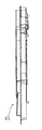
(パチンコ機の正面構成)
図1は本実施形態のパチンコ機10の正面図であり、図2は、パチンコ機10の右側面図であり、図3は、その平面図である。図4および図5は、遊技盤30の正面図である。
(Front configuration of pachinko machine)
FIG. 1 is a front view of a
図1乃至図3に示すように、パチンコ機10は、当該パチンコ機10の外殻を形成する外枠11と、この外枠11の一側部に開閉可能に支持された内枠12とを備えている。外枠11は、木製の板材により全体として矩形状に構成され、小ネジ等の離脱可能な締結具により各板材が組み付けられている。なお、外枠11は、軽量化を図るために、樹脂やアルミニウム等の軽金属により構成されていてもよい。
前記内枠12の開閉軸線はパチンコ機10の正面からみて遊技球発射ハンドル18の設置箇所の反対側(図1のパチンコ機10の左側)で上下に延びるように設定されており、この開閉軸線を軸心にして内枠12が前方側に十分に開放できるようになっている。また、内枠12は合成樹脂、具体的にはABS(アクリロニトリルーブタジエンースチレン)樹脂から成る。こうすることで、粘性が高く衝撃に強くでき、低コストで製造できるという利点が発揮される。
As shown in FIGS. 1 to 3, the
The opening / closing axis of the
前面枠(セット)14には、下皿15と球抜きレバー17と遊技球発射ハンドル18と灰皿22と音出力口24(内枠12の左右上端部位置)が設けられている。球受皿としての下皿15は、ほぼ中央部に設けられており、後述の上皿19が満タンになった場合等に排出口16より排出される遊技球を停留する役割がある。球抜きレバー17は、下皿15内の遊技球を抜くためのものであり、この球抜きレバー17を図1で左側に移動させることにより、下皿15の底面の所定箇所が開口され、下皿15内に停留された遊技球を下皿15の底面の開口部分を通して遊技者の持球貯留箱(ドル箱)に排出することができる。
The front frame (set) 14 is provided with a
そして、遊技球発射ハンドル18は、下皿15よりも右方で手前側に突出するように配設されている。遊技者による遊技球発射ハンドル18の操作に応じて、遊技球発射装置(図示せず)によって遊技球が遊技盤30の方へ打ち込まれるようになっている。遊技球発射装置は、遊技球発射ハンドル18と発射ソレノイドなどで構成されている。
音出力口24は、内枠12の左右上端部位置に設けられたスピーカからの音を出力するための出力口である。また、灰皿22は、図1に示すように、下皿15の左方に設けられている。灰皿22は左右方向(水平方向)の軸線を軸心にして回動(例えば前方側に向けて前回り)するように支持されている。
The game
The
また、前面枠14は、内枠12に対して開閉可能に取り付けられており、内枠12と同様、パチンコ機10の正面からみて左側に上下に延びる開閉軸線を軸心にして前方側に開放できるようになっている。しかも前面枠14は内枠12の外側壁(リブ)内に嵌まり込むようにして取り付けられている。
つまり、この前面枠14の側面の少なくとも一部が内枠12の外側壁(リブ)内に嵌まり込むようにして取り付けられているので、内枠12と前面枠14との隙間から異物(針状あるいは薄板状等のものであって、具体的には針金、ピアノ線、セルロイド板等)を差し入れるなどの不正行為を防止できるようになっている。また、前面枠14は、内枠12と同様に、合成樹脂、具体的にはABS樹脂により構成されているので、粘性が高く衝撃に強くでき、低コストで製造できる。
The
That is, since at least a part of the side surface of the
一方、前面枠14の下部(上述の下皿15の上方位置)には、遊技球の受皿としての上皿19(図1参照)が前面枠14と一体的に設けられている。この上皿19は、遊技球を一旦貯留し、一列に整列させながら遊技球発射装置38の方へ導出するための球受皿である。この上皿19も下皿15と同様、表面層が難燃性のABS樹脂にて成形される構成となっている。
On the other hand, an upper plate 19 (see FIG. 1) as a receiving tray for game balls is provided integrally with the
前記内枠12は、外形が矩形状の樹脂ベースを主体に構成されており、樹脂ベースの中央部には略円形状の窓部孔が形成されている。
そして、樹脂ベースの後側には、図4および図5に示す遊技盤30が着脱可能に装着されている。図4および図5に示すように、遊技盤30は四角形状の合板よりなり、上部一方のコーナーが肩落ちされており(後に述べる)、その周縁部が樹脂ベース(内枠12)の裏側に当接した状態で取着されている。
The
A
従って、遊技盤30の前面部の略中央部分が樹脂ベースの窓部孔を通じて内枠12の前面側に露出した状態となっている。そして、ここでは、遊技盤30の前記内枠12の外枠11に対する枢着部(パチンコ機10の正面からみて左側に上下に延びる開閉軸線を軸心にした枢着)に近いコーナー(隅)が、図4および図5に示すように、略三角形状に角落ち(切り欠き)720されている。
Therefore, the substantially central portion of the front surface portion of the
次に、図4および図5を用いて遊技盤30の構成を説明する。図4および図5は遊技盤30の構成を示す正面図である。遊技盤30のやや下方位置には、左側に3つの一般入賞口31、31、31が階段状に配置され、右側に1つの一般入賞口31が配置されている。中央下方には、始動口33が配置され、後にも詳述するように此れらに対応した入球検出センサが、遊技盤30の背面に設けられており、これらのセンサは、図示しない電気配線を通じて後述する主制御基板(主制御装置)に接続されている。
そして、この一般入賞口31及び始動口33に遊技球が入球した場合には、上記各検出センサで検出され、この検出センサの出力に基づいて、上皿19(または下皿15)へ所定数の賞品球が払い出されると共に、始動口33に遊技球が入球した場合には、後述する抽選が開始されることになる。
Next, the configuration of the
When a game ball enters the general winning
尚、上記入賞感知センサにて各々検出された検出結果は、後述する主制御基板に取り込まれ、該主制御基板よりその都度の入賞状況に応じた払出指令(遊技球の払出個数)が払出制御基板に送信される。そして、該払出制御基板の出力により所定数の遊技球の払出が実施される。
かかる場合、各種入賞口に入賞した遊技球を入賞球処理装置に一旦集め、その入賞球処理装置で入賞球の存在を1つずつ順番に確認した上で払出を行う従来方式(いわゆる証拠球方式)とは異なり、本実施の形態のパチンコ機10では、各種入賞口毎に遊技球の入賞を電気的に感知して払出が直ちに行われる(すなわち、本パチンコ機10では入賞球処理装置を廃止している)。故に、払い出す遊技球が多量にあっても、その払出をいち早く実施することが可能となる。但し、本発明に従来の「証拠球方式」を適用してもよい。
The detection results detected by the winning detection sensors are taken into a main control board, which will be described later, and a payout command (the number of game balls to be paid out) according to the winning situation is paid out from the main control board. Sent to the board. Then, a predetermined number of game balls are paid out by the output of the payout control board.
In such a case, a conventional method (so-called evidence ball method) in which game balls won in various winning openings are once collected in a winning ball processing device and paid out after the winning ball processing device confirms the presence of winning balls one by one in order. Unlike the above, in the
また、遊技盤30の中央には液晶パネルを用いた装飾図柄表示装置42が配置されており、その左側部には、スルーゲート34が配置されている。このスルーゲートは、遊技球の通過によって、所定の抽選が行われて当選が出た結果、後述の始動口33の羽根物を開閉作動させる。
その他に、遊技盤30の左右下方位置には、上記一般入賞口31を備えた装飾部材35が設けられ、また、遊技盤30の下部にはアウト口36が設けられており、各種入賞装置等に入球しなかった遊技球はこのアウト口36を通って、遊技盤30裏面の図示しない球排出路の方へと案内されるようになっている。さらに、遊技盤30には、遊技球の落下方向を適宜分散、調整等するために多数の誘導釘が植設されているとともに、同様の機能を有する風車32が配設されている。
In addition, a decorative
In addition, a
また、遊技盤30には、遊技球発射装置38から発射された遊技球を遊技盤30上部へ案内するためのレールユニット50が取り付けられており、遊技球発射ハンドル18の回動操作に伴い発射された遊技球はレールユニット50を通じて所定の遊技領域に案内されるようになっている。レールユニット50はリング状をなす樹脂成型品(例えば、フッ素樹脂が添加されて成形されたもの)にて構成されており、内外二重に一体形成された内レール51と外レール52とを有する。
Further, the
なお、レールユニット50はフッ素樹脂を添加して成形されているので、遊技球の摩擦抵抗を少なくできる。内レール51は上方の約1/4ほどを除いて略円環状に形成され、一部(主に左側部)か内レール51に向かい合うようにして外レール52が形成されている。
かかる場合、内レール51と外レール52とにより誘導レールが構成され、これら各レール51、52が所定間隔を隔てて並行する部分(向かって左側の部分)により球案内通路が形成されている。なお、球案内通路は、遊技盤30との当接面を有した溝状、すなわち手前側を開放した溝状に形成されている。
In addition, since the
In such a case, a guide rail is constituted by the
内レール51の先端部分(図4および図5の左上部)には戻り球防止部材53が取着されている。これにより、一旦、内レール51および外レール52間の球案内通路から遊技盤30の上部へと案内された遊技球が再度球案内通路内に戻ってしまうといった事態が防止されるようになっている。外レール52の内側面には、遊技球の飛翔をより滑らかなものとするべく、つまり遊技球の摩擦抵抗を少なくするべく、長尺状をなすステンレス製の金属帯としての摺動プレートが取着されている。
A return
また、内レール51および外レール52の後側端縁(遊技盤30に対向する端縁)には、所定間隔をおいて複数個所に鋲56が形成されており、内レール51および外レール52は該鋲56を打ちつけるようにして遊技盤30に取り付けられている。
In addition, on the rear edge of the
遊技盤30の右下隅部は、証紙(例えば製造番号が記載されている)等のシール(図示せず)やプレートを貼着するためのスペースとなっている。遊技盤30の右下隅部に証紙等のシールを貼着することで、遊技盤30と証紙との一義性を持たせることができる。
The lower right corner of the
次に、遊技領域について説明する。遊技領域は、レールユニット50の内周部(内外レール)により略円形状に区画形成されている。本実施形態では、遊技領域を、パチンコ機10の正面から見て、内レール51および外レール52によって囲まれる領域のうち、内外レール51,52の並行部分である誘導レールの領域を除いた領域としている。
従って、遊技領域と言った場合には誘導レール部分は含まないため、遊技領域の向かって左側限界位置は外レール52によってではなく内レール51によって特定される。同様に、遊技領域の向かって右側限界位置は内レール51によって特定される。また、遊技領城の下側限界位置は遊技盤30の下端位置によって特定される。また、遊技領域の上側限界位置は外レール52によって特定される。
Next, the game area will be described. The game area is partitioned and formed in a substantially circular shape by the inner periphery (inner and outer rails) of the
Therefore, when it is referred to as a game area, the guide rail portion is not included, and the left limit position toward the game area is specified not by the
前記樹脂ベースにおいて、窓部孔(遊技盤30)の下方には、遊技球発射装置(図示せず)より発射された直後に遊技球を案内するための発射レールが取り付けられている。発射レールは、その後方の金属板を介して樹脂ベースに取付固定されており、所定の発射角度(打ち出し角度)にて直線的に延びるよう構成されている。従って、遊技球発射ハンドル18の回動操作に伴い発射された遊技球は、まずは発射レールに沿って斜め上方に打ち出され、その後前述した通りレールユニット50の球案内通路を通じて所定の遊技領域に案内されるようになっている。
In the resin base, below the window hole (game board 30), a launch rail for guiding a game ball immediately after being launched from a game ball launcher (not shown) is attached. The launch rail is fixedly attached to the resin base via a metal plate behind the launch rail, and is configured to extend linearly at a predetermined launch angle (launch angle). Accordingly, the game ball that is launched in accordance with the turning operation of the game ball launch handle 18 is first launched obliquely upward along the launch rail, and then guided to a predetermined game area through the ball guide passage of the
また、発射レールとレールユニット50(誘導レール)との間には所定間隔の隙間があり、この隙間より下方にファール球通路が形成されている。従って、仮に、遊技球発射装置38から発射された遊技球が戻り球防止部材53まで至らずファール球として誘導レール内を逆戻りする場合には、そのファール球がファール球通路を介して下皿15に排出される。
Further, there is a gap of a predetermined interval between the launch rail and the rail unit 50 (guidance rail), and a foul ball passage is formed below this gap. Therefore, if the game ball launched from the game ball launching device 38 does not reach the return
ファール球が誘導レール内を逆流してくる際、その多くは外レール52に沿って流れ、外レール52の下端部に到達した時点で下方に落下する。
When the foul ball flows backward in the guide rail, most of the foul ball flows along the
なお、詳しい図面の開示は省略するが、遊技球発射装置には、前面枠14側の球出口(上皿19の最下流部より通じる球出口)から遊技球が1つずつ供給される。また、遊技球発射装置には打球槌が設けられ、ソレノイドによる打球槌のスライド動作に伴い遊技球が発射される。
Although detailed disclosure of the drawings is omitted, game balls are supplied to the game ball launching device one by one from the ball outlet on the
また、前面枠14を閉鎖した状態では、当該前面枠14の裏面に設けられた球通路樋によりシャッタが押し開けられて略水平状態になり、排出口の方へ排出された遊技球はもれなく球通路樋を通って上皿19に排出されるようになる。従って、本パチンコ機10においては、前面枠14の開放に際し払出通路内等の遊技球がパチンコ機10外にこぼれ落ちてしまうといった不都合が防止できるようになっている。
Further, when the
前記内枠12の上側には、前面枠14が内枠12に対して開かれたことを検出する前面枠セット開検出スイッチが設けられている。前面枠14が開かれると、前面枠セット開検出スイッチからホール内(パチンコ店内)用コンピュータヘ出力されるようになっている。また、前面枠14が閉じられると、前面枠14の金属製の補強板が、内枠12の一対の金具に接触するようになっており、前面枠14のアースが確保されている。
On the upper side of the
ここで、前述した前面枠14について、図1乃至図3を参照しつつより詳細に説明する。
前面枠14には前記遊技領域のほとんどを外部から視認することができるよう略楕円形状の窓部101が形成されている。詳しくは、ベース部材が窓部101を形成する開口を備えており、その左右側の略中央部が、上下側に比べて比較的緩やかに湾曲して細化した形状となっている。なお、前記略中央部が直線状になるようにしてもよい。
Here, the
A substantially
加えて、前面枠14には、その周囲(例えばコーナー部分)に、演出装置700の一つとして、各種ランプ等の発光部が設けられている。これら発光部は、大当たり遊技状態時や羽根開放時等における遊技状態の変化に応じて点灯、点滅のように発光態様が変更制御され遊技中の演出効果を高める役割を果たすものである。例えば、窓部101の周縁には、LED等の発光部を内蔵した環状電飾部102が左右対称に設けられ、該環状電飾部102の中央であってパチンコ機10の最上部には、同じくLED等の発光部を内蔵した中央電飾部103が設けられている。
本パチンコ機10では、中央電飾部103が大当たりランプとして機能し、大当たり遊技状態時に点灯や点滅を行うことにより、大当たり遊技状態中であることを報知する。さらに、上皿19周りにも、同じくLED等の発光部を内蔵した上皿電飾部104が設けられている。
In addition, the
In the
その他、中央電飾部103の左右側方には、賞球払出し中に点灯する賞球ランプ105と所定のエラー時に点灯するエラー表示ランプ810、813(LED:後に言及)とが設けられている。また、環状電飾部102の下端部に隣接するようにして、内枠12表面や遊技盤30表面等の一部を視認できるよう透明樹脂からなる小窓部107が設けられている。この小窓部107の所定箇所を平面状としているので、遊技盤30の右下隅部に貼り付けられた証紙などを、小窓部107の当該平面状箇所から機械で好適に読み取ることができる。更に、遊技領域内にも、入賞口用等の電飾ランプ、LEDが存在するが、こうした発光部も演出装置700の一部を構成する。
In addition, on the left and right sides of the
また、図1に示すように、窓部101の下方には貸球操作部120が配設されており、貸球操作部120には球貸しボタンと、返却ボタンと、度数表示部とが設けられている。パチンコ機10の側方に配置された図示しないカードユニット(球貸しユニット)に紙幣やカード等を投入した状態で貸球操作部120が操作されると、その操作に応じて遊技球の貸出が行われる。球貸しボタンは、カード等(記録媒体)に記録された情報に基づいて貸出球を得るために操作されるものであり、カード等に残額が存在する限りにおいて貸出球が上皿19に供給される。返却ボタンは、カードユニットに挿入されたカード等の返却を求める際に操作される。
Further, as shown in FIG. 1, a ball
そして、度数表示部はカード等の残額情報を表示するものである。なお、カードユニットを介さずに球貸し装置部から上皿19に遊技球が直接貸し出されるパチンコ機、いわゆる現金機では貸球操作部120が不要となる。故に、貸球操作部120の設置部分に、飾りシール等が付されるようになっている。これにより、カードユニットを用いたパチンコ機と現金機との貸球操作部の共通化が図れる。
The frequency display unit displays remaining amount information such as a card. Note that the ball
(パチンコ機の背面構成)
図6は、パチンコ機10の背面図である。先ず、パチンコ機10の背面構成について全体の概要を説明する。パチンコ機10にはその背面(実際には内枠12および遊技盤30の背面)において、各種制御基板が上下左右に並べられるようにしてまたは前後に重ねられるようにして配置されており、さらに、遊技球を供給するための遊技球供給装置(払出機構)や樹脂製の保護カバー等が取り付けられている。
(Back view of pachinko machine)
FIG. 6 is a rear view of the
本実施形態では、内枠12または遊技盤30の裏面に主制御基板、第1副制御基板(音声ランプ制御基板)、第2副制御基板(表示制御基板)、払出制御基板、発射制御基板および電源基板が設けられている。
In the present embodiment, a main control board, a first sub control board (audio lamp control board), a second sub control board (display control board), a payout control board, a launch control board, and a back surface of the
また、発射制御装置312により、遊技者による遊技球発射ハンドル18の操作に従い発射ソレノイドの制御が行われ、電源制御装置313により、各種制御装置等で要する所定の電源電圧が生成され出力される。カードユニット接続基板314は、パチンコ機前面の貸球操作部120(図1参照)および図示しないカードユニットに電気的に接続され、遊技者による球貸し操作の指令を取り込んでそれを払出制御装置311に出力するものである。なお、カードユニットを介さずに球貸し装置等から上皿19に遊技球が直接貸し出される現金機では、カードユニット接続基板314は不要である。
The
払出制御装置311は、上記払出制御基板を透明樹脂材料等よりなる基板ケース315に収容して構成され、発射・電源制御装置313は、上記発射制御基板および電源基板を基板ケース316に収容して構成されており、カードユニット接続基板314は、基板ケース318に収容されている。
The
図6に示すように、払出制御装置311には状態復帰スイッチ321が設けられている。例えば、払出モーター部の球詰まり等、払出エラーの発生時において状態復帰スイッチ321が押下されると、払出モーターが正逆回転され、球詰まりの解消(正常状態への復帰)が図られるようになっている。また、電源制御装置313にはRAM消去スイッチ323が設けられている。
As shown in FIG. 6, the
そして、前記内枠12の外枠11に対する枢着部725(図3参照)に近い前記遊技盤30のコーナーが、図4および図5に示すように、略三角形状(遊技盤の中心側は円弧状)に角落ち720されている。前記枢着部725は、外枠11に固定のブラケット(上端部)(下端部は図外)に、内枠12に固定の取り付け金具を枢着することで構成されている。
The corner of the
ここで、上述したエラー状態などの状態報知について図1及び図6に基づいて述べる。[遊技球の払い出しに関するエラー報知]
(タンク球無し)
タンク球無しの報知は、タンクとタンクレールに遊技球が無いことを報知するもので、図1に示す右コーナーLED810が点灯し、図6に示すモニターLED811が消灯し、状態表示812が「1」を点滅表示する。
Here, status notifications such as the error status described above will be described with reference to FIGS. [Error notification regarding game ball payout]
(No tank ball)
The notification of no tank ball indicates that there is no game ball on the tank and the tank rail. The
(下受け皿満タン)
下受け皿満タンの報知は、図1に示す右コーナーLED813が点灯し、前記払出制御装置311も受けられたモニターLED(図示せず)が消灯する。そして、状態表示812が「2」を点滅表示する。
(Under tray full)
In order to notify that the lower tray is full, the
(払出ユニット異常)
払出モーター駆動中にも関わらず払出カウントスイッチに遊技球の通過がない状態を示すもので、右コーナーLED810が点灯し、モニターLED811が消灯し、状態表示812が、「3」を点滅表示する。
(Discharge unit error)
This indicates that the payout count switch does not pass through the payout count switch even when the payout motor is being driven. The
[電源に関するエラー報知]
(ヒューズ切れ1及びヒューズ切れ2)
ヒューズ切れ1は、図6に示す第1ヒューズ814に定格以上の電流が流れたとき、ヒューズ切れ2は、第2ヒューズ815に以上の定格以上の電流が流れたときに飛んでしまった状態であるが、このエラー状態報知は、表示されない。
[Error notification for power supply]
(Fuse blown 1 and fuse blown 2)
The blown
[その他のエラー報知]
その他のエラーとしては、「ガラス枠開放」、「内枠開放」、「遊技球等貸出装置未接続」、「遊技球等貸出装置通信異常」、「コマンド異常」、「コネクタ未接続」がある。そのうち、遊技球等貸出装置が未接続の場合は、モニターLED及びモニターLED(図示せず)が消灯する。そして、遊技球等貸出装置通信異常は、前記状態表示812が「U」を点滅表示する。
また、コマンド異常は、ハーネスの破損等によるコマンド不良を示すもので、前記状態表示812が「C」を点滅表示する(電源投入時にコマンド異常になった場合は点灯表示)。更に、コネクタ未接続は、モニターLED(図示せず)が消灯する(ただし、発射動作中は点滅する)。
尚、図6において、819は、遊技機電源コードを示し、820は、電源スイッチを示し、821は、外部接続アース線を示す。
[Other error notifications]
Other errors include “Glass frame open”, “Inner frame open”, “Game ball lending device not connected”, “Game ball lending device communication error”, “Command error”, “Connector not connected”, etc. . Among these, when the rental device such as a game ball is not connected, the monitor LED and the monitor LED (not shown) are turned off. Then, in the case of an abnormality in communication with a lending device such as a game ball, the
Further, the command abnormality indicates a command failure due to harness damage or the like, and the
In FIG. 6, 819 indicates a gaming machine power cord, 820 indicates a power switch, and 821 indicates an external connection ground wire.
次に、第1制御基板ユニット201について述べるが、これは、主たる制御を司るCPU、遊技プログラムを記憶したROM、遊技の進行に応じた必要なデータを記憶するRAM、各種機器との連絡をとるポート、各種抽選の際に用いられる乱数発生器、時間計数や同期を図る場合などに使用されるクロックパルス発生回路等を収容してなる主制御装置261が搭載されているものである。
Next, the first
図7、その他の図面に示すように、前記第1制御基板ユニット201は、第1ケース70及び第2ケース85を含む。この実施例では、第1ケース70が主制御装置261の制御基板(図外)を収容する容積のある方であり、第2ケース85がその蓋体に相当する方である。
この基板ユニット201は、前記第1ケース70側に設けられる第1封止部71と、前記第2ケース側に設けられる第2封止部86と、その第1封止部71と第2封止部86とを連結する封止部材87とを有し、その封止部材87によって前記第1封止部71と第2封止部86とが連結されている場合に前記制御基板を取り出すときには基板ユニット201を破壊するか或いは所定の部位を切断することを必要とするものである。
As shown in FIG. 7 and other drawings, the first
The
前記第1ケース70の第1封止部71と第2ケース85の第2封止部86とは対を成すもので、この実施例では、個別に使用することのできる5個の封止部(封止、開封の再使用不可)から構成されており、それぞれを、封止部材87を用いて封止するよう構成されたものであり、こうした封止構造は、公知に属するものと変わらないものであるから、ここでの詳細説明は省略する。
The
図7は、遊技球が流下する遊技領域を前面側に形成してある遊技盤30の裏面の斜視図であり、便宜上、その上部に位置する他の構成部材を消去して、その下部に設けた第1制御基板ユニット201及びその近傍を図示している。図8は、遊技盤30の裏面を別の方向から見た斜視図であり、図9は、その背面図であり、図10は、第1制御基板ユニット201を開閉機構410から取り外した状態を示す。
以下の説明において、前記第1制御基板ユニット201を基板ケースの名称で説明をする。
先ず、前記基板ケース201を遊技盤30に対して開閉させる開閉機構410について説明する。
この開閉機構410は、ヒンジ金具412と後述の第1係合部414とを備え、前記ヒンジ金具412は、後に詳述するが、回動連結のための軸411(軸形状は図示省略)を備え、コの字形に折り曲げられた一枚の支持板(約2mm厚の鋼板)からなる第1部材と、他端側は、その軸411を基点にして回動するように枢着された第2部材とで構成されている。前記軸411は、リベット構造(カシメ)であり、その両端部を変形させることよって容易に抜き取り出来ないようにされている。
FIG. 7 is a perspective view of the back side of the
In the following description, the first
First, the opening /
The opening /
このヒンジ金具412について、更に、図11、図12及び図15乃至図19に基づいて詳述する。
このヒンジ金具412の第1部材がネジ連結部401を有し、該ネジ連結部401が、後述の球集合板460に対して、その遊技盤30への取り付け面側から2本のネジ421によりネジ止めされ、前記球集合板460が遊技盤30の裏面に固定された後には前記ネジ連結部401のネジ連結が解除できないようにすると共に前記球集合板460が取り外された後には該ネジ連結の解除が可能であることで、例えば廃棄処分等において、前記球集合板460(その連結部)を破壊することなく前記ヒンジ金具412を取り外し可能とし、リサイクル性を改善している。
更に、具体的には、前記ネジ連結部401は、前記開閉のための前記軸411を貫設した前部連結体401A、401Aと、該前部連結体401A、401Aに一体のネジ止め部401Fと、これに連続する支え部401C(図19参照)とを有し、且つ、該ネジ連結部401のネジ止め部401Fは、平板状体で構成され、その一端部の両側部から前記前部連結体401A、401Aが、側面視でコの字型を呈するように、夫々折り曲げ形成され、前記支え部401Cも平板状体で構成されている。
The hinge fitting 412 will be further described in detail with reference to FIGS. 11, 12, and 15 to 19.
The first member of the hinge fitting 412 has a
More specifically, the
また、前記ヒンジ金具412の第2部材が、やはり実質的にコの字型を呈するように夫々折り曲げ形成された後部連結体401B、401Bを有し、該後部連結体401B、401Bは、これに一体の支持面部401Dを介して、前記第1係合部414に繋がり、前記支持面部401Dが後述の連結台座部材430の側面を接当支持している。更に、前記基板ケース201の一側部側に位置する前記ヒンジ金具412の後部連結体401Bは、前記基板ケース201の一側部側に位置する前記前部連結体401Aの外側に位置されて軸支され、該後部連結体401Bから第1係合部414にかけてその横断面がL型に形成され、前記第1係合部414が前記後部連結体401Bから所定距離離れた位置に設けられている。
更に、前記ヒンジ金具412には補強体401Eが設けられ、後述のボックス基台501及び前記基板ケース201の被覆状態において、該補強体401Eが前記ボックス基台501の一部(凹部)に入りこんでいる。
尚、前記ヒンジ金具412の2本の軸411は、夫々カシメにより前記前部連結体401A、401A及び前記後部連結体401B、401Bに対して位置固定されているが、この軸411は、前記前部連結体401A、401A及び前記後部連結体401B、401Bの間隔が確定的なものであるところから、1本の軸であってもカシメによる枢支連結が十分に可能であるので、1本の軸が用いられてもよい。
In addition, the second member of the
Further, the
The two
前記ヒンジ金具412のネジ連結部401のネジ止め部401Fの底部部分には2個のネジ孔422が設けられ、遊技盤30の裏面に固定される球集合板460(遊技盤30の前面の入賞口に入球した遊技球を遊技盤裏面において集合させて排出する通路を形成しているもの)に対してネジ固定される。
Two screw holes 422 are provided in the bottom portion of the
ここで、台座部材としての前記球集合板460について説明する。
前記球集合板460は、遊技盤30の前面から一般入賞口、始動口、大入賞口から裏面に抜けた遊技球を案内する球集合樋を形成した樋形成側部460Aと、電気部品を敷設する電気部品敷設側部460Bとの二層構造(遊技機表裏の方向)となっており、前記樋形成部460Aが遊技盤30に直接固定され、電気部品敷設部460Bは、この樋形成部460Aの裏面に嵌合され、一体ユニット化される構成となっている。そして、前記連結台402は、前記樋形成側部460Aの一側に設けられている。
そして、この電気部品敷設部460Bに敷設される電気部品としては、中継基板470をはじめとして、一般入賞口の入賞検知センサ、始動口33の入賞を検知するセンサ、可変入賞装置(大入賞口)等がある。
Here, the said ball |
The
And as an electrical component laid in this electrical
次に、ボックス基台501について述べる。
このボックス基台501は、基板ケース201の支持基台として機能するものであり、前記球集合板460を略被覆する大きさに構成され、その表面側は、区画リブが設けられて強度向上を図ったおり、また、その長手方向の一端、ここでは、上記ヒンジ金具412とは反対側において、前記球集合板460の樋形成側部460Aに形成された軸受け部502に回動自在に軸支、連結され、これにより前記球集合板460に対して開閉自在とされている。前記基板ケース201は、このボックス基台501が閉じられ、前記球集合板460を被覆した状態で、その上から回動によって、該ボックス基台501の上部を覆う状態となる。
Next, the
The
次いで、前記ヒンジ金具412の固定構造について述べる。
図7乃至図19に示すように、前記ヒンジ金具412のネジ連結部401は、前記球集合板460(台座部材)に対して、その遊技盤30(遊技部材)への取り付け面側からネジ止めされ、前記球集合板460が遊技盤30の裏面に固定された後には前記ネジ連結部401のネジ連結が解除できないようにすると共に前記球集合板460が取り外された後には該ネジ連結の解除が可能であることで、例えば廃棄処分等において、前記球集合板460を破壊することなく前記ヒンジ金具412を取り外し可能とするために、次の構造を採用している。
Next, a fixing structure of the hinge fitting 412 will be described.
As shown in FIGS. 7 to 19, the
即ち、前記球集合板460の裏面に、遊技機裏面側に向けて、約50mmの高さに突出する連結台402が、その前面側に空間を形成する状態で球集合板460と一体成型により設けられている。
そして、この連結台402には、前記ネジ連結部401のネジ止め部401F及び前部連結体401A、401Aを挿入するための縦スリット403が、遊技盤30の平面に略平行な方向で形成され、また、前記ネジ連結部401の前部連結体401A、401Aを挿入するための横スリット404、404が、遊技盤30の平面に略直行する方向で前記縦スリット403に連続する状態で形成され、且つ、前記連結台402の上部に、前記ネジ止め部401Fを前面側からの螺合で支持するネジ受け部405が設けられている。このネジ受け部405に2本のネジを螺合させるボス部が備えられており、その背面視(台の頂部から見た)では、凹の形状を呈し、その二つの突出部がその切り欠き貫通部を残して連結台402の壁面に一体的形成され、残る三辺が前記縦スリット403と横スリット404、404によって連結台402の壁面から離れ、所謂片持ち支持の構造となっている。このように、前記縦スリット403と横スリット404、404は、ネジ受け部405の成型によって形成されるもので、その意味ではスリットと呼称するのに代えて、前記ヒンジ金具412の取り付け用の挿入溝と言える。
That is, by connecting the
The
また、前記縦スリット403が位置する連結台402の一側部(球集合板460の中心側に位置)に、該縦スリット403への前記ネジ止め部401Fの挿入後において外部に位置する前記支え部401Cに接当して支持する支持台部406が前記連結台402と一体的に形成されている。勿論、この支持台部406が連結台402と分離される構造としても、機能上問題はない。
更に、前記連結台402の横スリット404、404に対応する内部位置で、且つ、前記支持台部406の上面の延長線上で、前記ネジ連結部401の両側部を案内する細幅のガイドリブ407、407が夫々設けられている。
また、前記連結台402の内部で、前記ネジ連結部401が挿入される奥側の内面壁の幅方向略中央位置に、上下の方向に伸びる1本の補強リブ408が形成され、該補強リブ408の上端部が前記ネジ止め部401Fを下方から支持する位置に終端し、前記ネジ受け部405の下面との間にネジ止め部401Fを挿入できる間隙を残している。
Further, the support located outside is inserted into one side of the
Furthermore,
In addition, a reinforcing
上記開閉機構410の第1係合部414について述べる。
この第1係合部414は、前記ヒンジ金具412の後部連結体401Bと、支持面部401を介在させて、反対側に位置され、1枚の板状体で、先端が対向する鉤爪状の二股状係合片414Aに構成されている。この二股状の係合片414Aは、前記ヒンジ金具412の軸411と平行な方向に延び、従って、後述の連結台座部材430の第2係合部433との係合は、前記基板ケース201の幅方向(遊技機の上下の方向)に沿って行われることになる。
The
The
上記球集合板460については、その外周部の複数個所を遊技盤30に対して固定するが、そのうちの少なくとも一つが固定解除できないように、破断ネジ等でするか、ビス留めしたあと、ビス頭部を覆うキャップを取り付けるようにする等して、球集合板460が遊技盤30から容易に外されるのを防止する構造としてもよい。
そして、上記第1係合部414の係合片414Aは、後述の第2係合部433の舌片433a、433bとでもって、第1係合部414の抜け出し防止の規制機構440を構成する。
The
The engaging
次に、連結台座部材430について述べる。
この連結台座部材430は、前記開閉機構410と前記基板ケース210とにそれぞれ連結されるものであり、言わば従来から用いられていた基板ケース201を取り付けるための台座に相当するものであって、合成樹脂で成型されており、ここでは、幅は、基板ケース201の半分以下で、上下の長さは、その三分の一程度の小型のものであり、基板ケース201の第2ケース85の一端側のコーナー(背面視、左下方位置のコーナー)に位置され、その基板ケース201の側面に沿う側の一部が開放され、図18にも示すように、区画壁を形成する補強のためのリブが多数設けられ、また、破断ネジを収容する収容部435、435、435が形成されており、そこに破断ネジ(図示せず)がセットされるものであるが、周壁、リブの端面は同じレベルに形成され、第2ケース85の側面に密着接当可能にされており、反対側の側面(ボックス基台501側)は、略平坦に形成されている。
Next, the
The connecting
前記基板ケース201のうち、前記連結台座部材430と連結封止される部位である第1連結封止部450が、その第2ケース85の一端側のコーナー(背面視、左下方位置のコーナー)に設けられており、ここでは該基板ケース201の幅方向に、所定の間隔を隔てて4個突設されている。この第1連結封止部450は、第1ケース70の第1封止部71と第2ケース85の第2封止部86との位置と平面視で位相がずれるように変位して配置されており、従って、基板ケース201を背面(遊技機の背面から)から見たときに、前記第1封止部71と第2封止部86に重なることなく、視認できる状態にある。
即ち、前記第1封止部71と第2封止部86の位置する側に前記第1連結封止部450及び第2連結封止部432が配置され、且つ、前記基板ケース201の背面視(正面)において、前記第1、及び第2連結封止部450、432(こちらは極一部が見える)が見えるように、前記第1、及び第2封止部71、86と平面位相をずらせて配置(4個はが連続して直線状に並ぶ)されているのである。
In the
That is, the first
そして、前記連結台座部材430には、前記基板ケース201の前記第1連結封止部450と連結封止される部位である第2連結封止部432が、ここでは、4個が、前記4個の第1連結封止部450と対応する位置に突設されている。そして、前記前記第1、及び第2連結封止部450、432は、破断ネジ(頭部が千切れる)を用いて連結封止されるが、そのネジは、第2ケース85の側から挿入される。
The
前記連結台座部材430の内部に、前記開閉機構410の前記第1係合部414と係合する部位である第2係合部433が設けられる。この第2係合部433は、この実施例では、前記連結台座部材430の本体とは別体成型の後述する第2被覆部材430Bに取り付けられる。勿論、別体の第2被覆部材430Bが存在せず、第2係合部433A,433Bが連結台座部材430の樹脂成型時に埋め込たり、或いは、それ自体の弾性変形を利用して、連結台座部材430に形成された挿入部434の内部に挿入設置されるように構成されてもよいものである。
A
前記第2係合部433は、ここでは、弾性を備えた一枚の薄い板体(鋼板)で構成され、その所定箇所を、前記第1係合部の進行方向側が遊端部となるように、コの字に打ち抜いて舌片433a,433bを形成し、該舌片433a,433bを、コの字の付け根部で曲げることで弾性係合爪を形成し、且つ、前記第1係合部414を金属製の平板状体で構成し、そこに先端が対向する鉤爪状の二股状の係合片414Aを形成することによって、該係合片414Aに前記舌片433a,433bの係合爪を係合させ、それぞれ抜け出し防止の規制機構440を構成しているのである。そして、前記開閉機構410の前記第1係合部414を挿入して前記連結台座部材430の内部の前記第2係合部433に係合させるために前記連結台座部材430に、挿入部434が形成されている。
Here, the
このように、前記規制機構440は、前記第1係合部414と前記第2係合部433との係合において、前記開閉機構410の第1係合部414が前記挿入部434に挿入されて前記第2係合部433と係合されたあとにその挿入方向とは逆の抜き出す方向への移動を規制するものである。
As described above, the
ここで、更に、前記連結台座部材430について詳述する。前記連結台座部材430は、前記基板ケース201よりも小さく構成され、前記基板ケース201のうち、上述のように基板ケース201の裏面側で一端側、即ち、一端側のコーナー(背面視、左下方位置のコーナー)に寄せて位置され、封止、連結されるように構成されているものである。前記第2係合部433を被覆するべく前記連結台座部材430には被覆部材430Aおよび第2被覆部材430Bが備えられている。この被覆部材430Aと第2被覆部材430Bとは別体構成とされ、且つ、その少なくとも一方、ここでは前記第2被覆部材430Bに凹面が形成され、他方、即ち、被覆部材430Aに対向するよう組み合わせることで前記第1係合部を挿入するための前記挿入部434を形成している。具体的には、前記挿入部434は、その入口が、入口側から内部に向かって幅狭となるようにテーパ状に形成され、且つ、挿入方向に沿って複数、ここでは4本の案内リブが形成されている。図中、430Dは、前記第2被覆部材430Bの側部に設けた係合突片であり、はめ込みに際して、前記被覆部材430Aの対応する箇所に係合される。
Here, the
そして、この被覆部材430Aに、前記第2係合部433が設けられるが、その第2係合部433の薄板を、被覆部材430Aに形成した係止突片430Cに、その入口434Aの側からスライド挿入して係止させる。
前記第2被覆部材430Bは、前記被覆部材430Aよりも小さく構成され、前記連結台座部材430と前記基板ケース201とが連結した状態においては、前記被覆部材430Aの取り外し方向側に前記基板ケース201が位置された状態となり、前記基板ケース201と前記被覆部材430Aとにより被覆された状態となるように構成されているものである。
The covering
The
上述のように、前記基板ケース201を、前記球集合板460の少なくとも一部を被覆する状態と露出する状態とに開閉するための開閉機構410が設けられ、前記開閉機構410と前記基板ケース201とにそれぞれ連結される連結台座部材430が設けられ、更に、前記基板ケース201は、前記連結台座部材430と連結封止される第1連結封止部450を備え、前記連結台座部材430は、前記基板ケース201と連結封止される第2連結封止部432と前記開閉機構410に対する第2係合部433とを備え、前記開閉機構410は、前記第2係合部433に係合する前記第1係合部414と、開閉のための軸を有するヒンジ金具412とを備え、該ヒンジ金具412の一方がネジ連結部401を有し、前記開閉機構410の第1係合部414と前記連結台座部材430の第2係合部433は、両者が一旦係合された後は破壊等強制解除の痕跡を残すことなく解除できないように構成されており、前記ネジ連結部401が、前記球集合板460に対して、その遊技盤30への取り付け面側からネジ止めされ、前記球集合板460が遊技盤30の裏面に固定された後には前記ネジ連結部401のネジ連結が解除できないようにすると共に前記球集合板460が取り外された後には該ネジ連結の解除が可能であることで、前記球集合板460を破壊することなく前記ヒンジ金具412を取り外し可能としたことにより、遊技機の開閉式の基板ケース201のヒンジ金具412の取り付けをネジで行いながら組み付け完了後は取り外し不能として不正対策に寄与でき、また、必要に応じて球集合板460を破壊しないでネジを取り外すことで、球集合板460から取り外し可能とし、リサイクル性を向上させることができるのである。
そして、ヒンジ金具412は、そのネジ連結部401のヒンジ金具412のカシメを行った後の状態で連結台402に対して差し込み、しかる後にその遊技盤30への取り付け面側から連結台402に対してネジ止めすることができる予め一体化させた状態での装着方式を採っているので、連結台402へのネジ止め後に球集合板460を持った状態でヒンジ金具412のカシメを行わなければならないという煩わしさはなく、ヒンジ金具412の連結台402への装着が容易に行い得るものでありながら、不正対策を可能にできるものである。
As described above, the opening /
Then, the hinge fitting 412 is inserted into the connecting
そして、前記球集合板460の裏面に、遊技機裏面側に向けて突出する連結台402が、その前面側に空間を形成する状態で一体成型により設けられており、前記ネジ連結部401は、前記開閉のための軸を貫設した前部連結体401A、401Aと、該前部連結体401A、401Aに一体のネジ止め部401Fとを有し、前記連結台402には、前記ネジ連結部401のネジ止め部401F及び前部連結体401A、401Aを挿入するための縦スリット403が、遊技盤の平面に略平行な方向で形成され、また、前記ネジ連結部401の前部連結体401A、401Aを挿入するための横スリット404、404が、遊技盤30の平面に略直行する方向で前記横スリット404、404に連続する状態で形成され、且つ、前記連結台401の上部に前記ネジ止め部401Fを前面側からの螺合で支持するネジ受け部405が設けられていることで、球集合板460にヒンジ金具412(ネジ止め部401Fと前部連結体401A、401A)の取り付けを行うに、成型ではあるが台構造とし、ヒンジ金具412の位置を所要高さに設定できながら該連結台402に縦、横スリット403、404、404を形成して差し込むように構成したことによって、連結台401の強度を確保し、且つ、ヒンジ金具412を球集合板460と一体成型するのではなく後付けできるようにするものでありながら、ヒンジ金具412の一部を連結台401の内側においてネジ止めでき、遊技機の前面側からのネジ止めで遊技盤30に対する球集合板460の取り付け後は外部からネジを外せないようにすることができた。これによって、破断ネジを用いる必要もなく、又、ヒンジ金具412を一体成型で埋め込んでしまうことなく、必要に応じて取り外しすることができる。
And, on the back surface of the
また、前記ネジ受け部405は、前記縦スリット403及び横スリット404、404を形成するようにして前記連結台401の上部に、その一側部で片持ち支持されるように一体成型されており、前記ネジ連結部401は、前記ネジ止め部401Fに連続して延設された支え部401Cを有し、前記縦スリット403が位置する連結台402の一側部に、該縦スリット403への前記ネジ止め部401Fの挿入後において外部に位置する前記支え部401Cに接当して支持する支持台部406が前記連結台401と一体的に形成されていることにより、ヒンジ金具412を差込方式で後付けできるように、前記縦スリット403及び横スリット404、404を形成したことで、そのネジ受け部405は結果として片持ち支持される構造となり、その為、ここにネジ止めされたヒンジ金具412のネジ連結部401に、その前部連結体401A、401Aを介して伝わる基板ケース201等の荷重(基板ケース201の特に閉鎖時にも曲げモーメントが作用する)が、その片持ち支持のネジ受け部405を連結台内方に向けて折るように作用することになるのであるが、これを、前記支え部401Cを介して、前記支持台部406で受け止め、前記ネジ受け部405が撓まないように支持することができるのである。この際、前記支持台部406が前記連結台401と一体的に形成されていることで、十分な強度でもって、荷重に対向してネジ受け部405を保護できるのである。
The
更に、前記ネジ連結部401のネジ止め部401Fは、平板状体で構成され、その一端部の両側部から前部連結体401A、401Aが、側面視でコの字型を呈するように、夫々折り曲げ形成されているので、ヒンジ金具412のネジ連結部401を、平板状体を折り曲げた簡単な構造で得ることができると共にコの字型として支持強度を発揮させることができる。
そして、前記ヒンジ金具412の他方が後部連結体401B、401Bを有し、該後部連結体401B、401Bは、これに一体の支持面部401Dを介して、前記第1係合部414に繋がり、前記支持面部401Dが前記連結台座部材430の側面を接当支持しているので、ヒンジ金具412の他方が後部連結体401B、401Bを有し、これに支持面部401Dが一体となっていて、この部分が連結台座部材430の側面に接当されることで、基板ケース201の開閉に際して、この支持面部401Dを介して開閉力を伝達できて、第2係合部433のみに力が作用することがないようにして、支持力を分散させることができるのである。
Further, the
The other of the
また、前記基板ケース201よりも前方側において、ボックス基台501が、前記球集合板460を直接に被覆する状態と露出する状態に開閉するように、前記基板ケース201の前記ヒンジ金具412とは反対側において回動自在に設けられ、前記ヒンジ金具412には補強体401Eが設けられ、前記ボックス基台501及び基板ケースの被覆状態において、該補強体401Eが前記ボックス基台501の一部(凹部)に入りこんでいることにより、ボックス基台501により球集合板460が被覆される構成において、前記ヒンジ金具412の補強体401Eがボックス基台501の一部に入り込む構造としたことで、ヒンジ金具412に加わる荷重を、ボックス基台501に伝達して分散支持させることが出来るのである。尚、この補強体401Eのボックス基台501への入り込みとしては、ボックス基台501に凹部を形成してもよく、壁面にスリットを形成してもよく、荷重が作用したときの僅かの撓みにより生じる接当状態で支持作用が得られればよくて、常時接触状態でなくともよい。
Further, on the front side of the
更に、前記連結台402の横スリット404、404に対応する内部位置で、且つ、前記支持台部406の上面の延長線上で、前記ネジ連結部401の両側部を案内するガイドリブ407、407が夫々設けられているので、ヒンジ金具412のネジ連結部401を縦、横スリット403、404、404を通して連結台402に挿入する際に、そのネジ連結部401のネジ止め部401Fとこれに連続して延設された支え部401Cを前記支持台部406の上面に載せ、滑らせて挿入して行くと、その支持台部406の上面を過ぎたところからは、そのネジ止め部401Fの両側部分を前記ガイドリブ407、407に乗せて案内させながら連結台402の内部へとスムースに挿入することができる。
Further, guide
また、前記連結台402の内部で、前記ネジ連結部401が挿入される奥側の内面壁の幅方向略中央位置に、上下の方向に伸びる補強リブ408が形成され、該補強リブ408の上端部が前記ネジ止め部401Fを下方から支持する位置に終端しているので、ネジ連結部401を連結台402の内部に挿入したときに位置を安定させることができ、以って、ネジ止め部401Fのネジ受け部405に対するネジ止め作業を楽に行い得ると共にネジ連結部401の端部を支持することでのネジ受け部405の荷重による撓みに対抗することができるのである。
Further, a reinforcing
そして、前記基板ケース201の一側部側に位置する前記ヒンジ金具412の後部連結体401B、401Bは、前記基板ケース201の一側部側に位置する前記前部連結体401A、401Aの外側に位置されて軸支され、該後部連結体401B、401Bから第1係合部414にかけてその横断面がL型に形成され、前記第1係合部414が前記後部連結体401B、401Bから所定距離離れた位置に設けられているので、ヒンジ金具412による基板ケース201の支えを、基板ケース201の長手方向の略中間部側にすることによって、例えば基板ケース201の長手方向側の端部での連結支持に比べて、安定支持できることになるが、そのために前記第1係合突片部414を後部連結体401B、401Bから所定距離だけ離すようにする必要があり、この部分をL型構造とすることで、出来るだけ軽量化しながら十分な強度を付与できて、基板ケース201の支持を強固に安定させることができるのである。
And the
また、前記ヒンジ金具412の2本の軸411、411(軸形状は図示省略)は、夫々カシメにより前記前部連結体401A、401A及び前記後部連結体401B、401Bに対して位置固定されるものであるから、その連結は一端行われると解除できないものであり、これにより、ネジ連結などのヒンジ金具では容易に分離されて基板ケースを取り替えられてしまう危険性を回避できることになり、このヒンジ金具412をターゲットとした不正を回避できるものである。
Further, the two
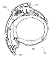
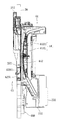
(特徴構成)
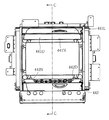
本実施形態のパチンコ機10においては、図4および図5に示すように、可変表示装置の表示部の周囲にセンターフレーム43が配置され、図20、図21、図29および図30に示すように、裏面側にはシャッタユニット44が配置されている。
(Feature configuration)
In the
図4および図5に示す可変表示装置ユニット35は、遊技領域の中央部に配置され、遊技領域内の大きな面積を占める大型の役物となっており、電動役物ユニットあるいはセンター役物とも称される。この可変表示装置ユニット35は、表示部として装飾図柄表示装置42を中央に備え、該装飾図柄表示装置42の上辺部、下辺部、左辺部および右辺部をセンターフレーム43で包囲するようにして構成されている。センターフレーム43は、図22ないし図28に示すように、装飾図柄表示装置42が配置される概略横長の楕円形状の開口を内側に包含する枠状の部材となっていて、右側部は遊技領域の右側部分をほぼ覆うように幅広に形成されるとともに若干下方に延出し、全体として正面視概略「9」の字形状の外形を有している。また、外周にはネジ孔を有するフランジ43Fが設けられており、木ネジ等により遊技盤30上に前方側から固定されるようになっている。
The variable
図22ないし図28に示すように、センターフレーム43の上端縁の右側部分は、左側部分よりも一段高く上方へ膨出して膨出部371を形成している。この膨出部371には、前面部に引き戸状に開閉可能に構成された扉部材(図示せず)が配置されるとともに、該扉部材より後方には光透過性を有する樹脂を成形してなり表面に図柄が形成された装飾部材(図示せず)が配置されており、扉部材が開いた状態では該装飾部材が露出し、さらに該装飾部材には裏側からLEDにより光が照射されて該装飾部材の前方へ透過し、これにより効果的に演出がなされるようになっている。
As shown in FIGS. 22 to 28, the right side portion of the upper edge of the
センターフレーム43の外周縁には、図22、図29および図30に示すように、左側端部から上端部を経て右側部分の下端部まで一定幅で細長に延びる上側端面372が形成されている。センターフレーム43の上方へ飛来した遊技球は、上記上側端面372上を転動して右下または左下へ流下する。
22, 29, and 30, an
図22ないし図28に示すように、センターフレーム43の概略楕円形状の開口には、該開口にほぼ等しい寸法、形状を有する透明樹脂板390が裏側から取り付けられて該開口の裏面側を覆い、該開口の最内奥部よりも後方へ遊技球が進入しないように遮蔽している。
As shown in FIGS. 22 to 28, a
図22および図24に示すように、センターフレーム43における前記上側端面372の左端部の直下部には入球口391が形成され、該入球口391は、センターフレーム43の左側部の内部に形成された球誘導路に連通している。該球誘導路は、センターフレーム43の左側部に沿って下方に延び、下端部に、図29および図30にも示すようにセンターフレーム43の中央側にむけて開口する袖開口393が形成されている。
As shown in FIGS. 22 and 24, a
センターフレーム43の下側部には、遊技球が左右に転動するステージ(転動面部)429H、429Lが形成されている。該ステージ429H、429Lは、横長の楕円形状に形成されたセンターフレーム43の外形の下側部に沿った円弧形状に形成され、内周側(上側)の上ステージ429Hと、該上ステージ429Hから間隔をおいて外周側(下側)に形成された下ステージ429Lとにより上下2段に構成されており、後側端縁は基本的に前記透明樹脂板390の表面に当接している。上ステージ429Hは、両側から中央にむかって、前記透明樹脂板390の表面に当接しながら、下方に緩やかに湾曲する円弧形状をなして延びているが、中央部すなわち下端部は、前方に湾曲しながら迫り出して、透明樹脂板390の表面から前方に離間するように形成され、透明樹脂板390の表面との間に落下孔429Pが形成されている。下ステージ429Lは、全体的に下方に緩やかに湾曲する円弧形状を有し、中央部すなわち下端部には、前方に若干下傾する溝状誘導部が形成されている。
On the lower side of the
上記入球口391に入球した遊技球は、球誘導路内を流下し、上記袖開口393から上ステージ429Hへ案内される。袖開口393から出てきた遊技球は、上ステージ429H上を左右に往復するように転動し、その途上で前記落下孔429Pから下ステージ429Lへ落下し、該下ステージ429L上を左右に往復するように転動して、その途上で前面側へ転落するか、あるいは、稀に中央でうまく前記溝状誘導部により案内されて前面側へ排出され、直下に位置する第1の始動入賞装置33に高確率で入球することとなる。
The game ball that has entered the
センターフレーム43は、図29および図30にも示すように、遊技盤30の貫通孔に前側から挿入するようにして取り付けられている。遊技盤30の裏面側には、貫通孔を覆うようにしてシャッタユニット44が取り付けられている。
As shown in FIGS. 29 and 30, the
シャッタユニット44は、図31ないし図43に示すように、遮蔽部材(シャッタ)441、442を開閉可能に支持する装置であり、遊技盤30の貫通孔の大部分を包含する概略矩形状の枠状に構成されている。
As shown in FIGS. 31 to 43, the
図42および図43に示すように、シャッタユニット44の左側にはレール形成部材443Lが配置されている。レール形成部材443Lは、上下にやや長く延び、上端部に、上下方向にやや幅狭で後方にやや長く延出する上延出部443Tを有するとともに、下端部に、上下方向にやや幅広で後方にやや短く延出する下延出部443Bを有する、概略コ字形状の平板状に樹脂を成形してなる部材であり、シャッタユニット44の左側面部を構成している。
レール形成部材443Lの内側面には、前側端縁に沿って上下に直線状に延びる縦レール443Aが形成され、該縦レール443Aの上端部および下端部にそれぞれ隣接して後方に延びる上レール443Bおよび下レール443Cが形成されている。縦レール443Aは、レール形成部材443Lを厚み方向に貫通するように形成され、また、中央部に仕切板443Sが形成されて上下に仕切られている。上レール443Bは、縦レール443Aの中央よりやや上方の高さ位置から、該縦レール443Aの後側に隣接しながら上方に延び、縦レール443Aの上端近傍の高さ位置で後方に湾曲するように屈曲し、この屈曲部分から、前記上延出部443T内を緩い角度で上傾しながら後方に延びていて、全体として「へ」の字形状をなすように形成されている。下レール443Cは、縦レール443Aの下端よりやや上方の高さ位置において該縦レール443Aの後側に隣接する位置から、前記下延出部443B内を急角度で下傾しながら後方に直線状に延びるように形成されている。
レール形成部材443Lの内側面において、上記縦レール443A、上レール443Bおよび下レール443Cにより前側、上側および下側を包囲される領域には、この領域に対応する形状を有する平板状の内装部材444Lが取り付けられる。
As shown in FIGS. 42 and 43, a
On the inner surface of the
On the inner side surface of the
レール形成部材443Lの外側すなわち左側には、シャッタ駆動機構445Lが設けられている。シャッタ駆動機構445Lは、左右方向の軸を中心に回転するピニオン446L、該ピニオン446Lに前後両側から噛み合うように対向配置され互いに逆方向に上下動する2本のラック447T、447B、上記両ラック447T、447Bを両側からスライド自在に保持するラック保持部材448L、上記ピニオン446Lに連結されたモータ449L等を含んで構成されている。
A
シャッタユニット44の右側には、上記左側のレール形成部材443L、内装部材444Lおよびシャッタ駆動機構445Lとほぼ左右対称に構成されたレール形成部材443R、内装部材444Rおよびシャッタ駆動機構445Rが配置されている。
Arranged on the right side of the
上記左右両側のレール形成部材443R、443Lの各々の上端縁の間、ならびに各々の上延出部443Tの延出端縁の間には、それぞれ板金よりなる補強板450、451が架設されるとともに、各々の下延出部443Bの前後両端縁の間には、それぞれ板金よりなる補強板452、453が架設され、これによりシャッタユニット44が必要な強度を有する枠体として構成されている。なおレール形成部材443R、443Lの下延出部443Bの前端縁は下レール443Cに沿って傾斜するように形成され、後端縁は垂直に延びるように形成されており、これにより上記補強板452、453は下方へかけて漸次幅狭となる概略谷形状をなすように配置されている。また、左右両側のレール形成部材443R、443Lの各々の後端縁(上延出部443Tと下延出部443Bとの間の端縁)の間には、樹脂を矩形状に成形してなる内側装飾枠部材454および外側枠部材455が、前後にこの順に重ねるようにして架設されている。さらに、シャッタユニット44の上面部および両側面部の最外部には、それぞれ樹脂よりなる固定部材456、457R、457Lが取り付けられている。該固定部材456、457R、457Lにはそれぞれフランジが形成されていて遊技盤30の裏面に木ネジにより固定されるようになっているとともに、両側面部の固定部材457R、457Lにはそれぞれモータ449L、449Rが支持固定され、上面部および両側面部の固定部材456、457R、457Lには該モータ449L、449Rを駆動させるための電気部品を搭載する基板(図示せず)が支持固定されるようになっている。
Reinforcing
シャッタユニット44の下には、図29および図30に示すように、前述の球集合板460が配置され、該球集合板460は遊技盤30の裏面に固定されており、シャッタユニット44は、該球集合板460の上端面に当接するようにして配置されている。この構成により、シャッタユニット44を遊技盤30の裏面に取り付ける際に、シャッタユニット44を球集合板460の上端面の上に載置した状態で、即ちシャッタユニット44を球集合板460により取付位置に保持した状態で取付作業を行うことができるので、作業性が良好となっている。
Under the
遮蔽部材441、442は、上側の遮蔽部材(以下、上側部材とも称す)441と下側の遮蔽部材(以下、下側部材とも称す)442とから構成され、これらが互いに離隔および近接することにより上下に開閉する構成となっている。
The shielding
図42および図43に示すように上側部材441は、概略横長の長方形状の平板状の部材となっており、裏面側は垂直面、表面側は上端から下端にかけて緩やかに湾曲しながら漸次前方に膨出する形状となっている。上側部材441はさらに、上側の分割体441Hと下側の分割体441Lとに分割構成され、両分割体441H、441Lは境界に沿って一直線に並ぶように裏面側の左右両端部に形成された軸挿通部(図示せず)に軸ピン441Pが両側からそれぞれ挿通されることにより、回動自在に連結されている。即ち、遮蔽部材441、442の一部をなす上側部材441が、該上側部材441のスライド方向に沿って並置された複数の部材すなわち上下の両分割体441H、441Lが回動可能に連結された構成となっている。なお上記軸ピン441Pは、両分割体441H、441Lを折り畳んだ状態でのみ着脱することができ、両分割体441H、441Lが一平面上に位置するように開いた状態では脱落し得ない構成となっている。
As shown in FIG. 42 and FIG. 43, the
上記上側の分割体441Hにおける両側面の上端部ならびに下側の分割体441Lにおける両側面の後上の隅部には、それぞれスライダ458A、458Bが両側から取り付けられ、両スライダ458A、458Bは前記上レール443Bに係合して該上レール443B内にスライド自在に保持される構成となっている。下側の分割体441Lにおける両側面の前下の隅部には、先端より係合ピンがさらに突出した構成を有するスライダ(以下、係合スライダとも称す)459が両側から取り付けられており、該係合スライダ459は前記縦レール443Aに係合して該縦レール443A内にスライド自在に保持されるとともに、該係合スライダ459の係合ピンがレール形成部材443R、443Lを貫通し、前記シャッタ駆動機構445R、445Lにおける一方のラック447Tの上端に形成された係合孔に挿通されて係合し、該ラック447Tの上下動にともなって上下動する構成となっている。
下側部材442は、前記上側部材441とほぼ上下対称をなす概略横長の長方形状の平板状の部材となっており、裏面側は垂直面、表面側は下端から上端にかけて緩やかに湾曲しながら漸次前方に膨出する形状となっていて、前記上側部材441とともに閉じた状態で、全体として緩やかに前方に湾曲しながら膨出する周面状の前面、一垂直面をなす後面および概略弓形状の両側面を構成している。
下側部材442(および上側部材441)の左右方向の寸法(幅)は、前記第1制御基板ユニット201(厳密には、該第1制御基板ユニット201に収容された主制御基板)の左右方向の寸法(幅)に対応するもの、即ち該第1制御基板ユニット201(主制御基板)の左右方向の寸法(幅)と同等以上となっており、下側部材442(および上側部材441)は、該第1制御基板ユニット201(主制御基板)を幅方向において包含するように配置されている。
The
The horizontal dimension (width) of the lower member 442 (and the upper member 441) is the horizontal direction of the first control board unit 201 (strictly speaking, the main control board accommodated in the first control board unit 201). Of the first control board unit 201 (main control board) is equal to or greater than the horizontal dimension (width) of the first control board unit 201 (main control board), and the lower member 442 (and the upper member 441) is The first control board unit 201 (main control board) is arranged so as to be included in the width direction.
上記下側部材442における両側面の下端部には、前記上側部材441に取り付けられたスライダ458A、458Bと同一構成のスライダ458がそれぞれ両側から取り付けられ、該スライダ458は前記下レール443Cに係合して該下レール443C内にスライド自在に保持される構成となっている。上記下側部材442における両側面の前上の隅部には、前記上側部材441に取り付けられたものと同一の係合スライダ459が両側から取り付けられており、前記上側部材441の場合と同様に、該係合スライダ459は前記縦レール443Aに係合して該縦レール443A内にスライド自在に保持されるとともに、該係合スライダ459の係合ピンがレール形成部材443R、443Lを貫通し、前記シャッタ駆動機構445R、445Lにおける他方のラック447Bの下端に形成された係合孔に挿通されて係合し、該ラック447Bの上下動にともなって上下動する構成となっている。なお、左右のピニオン446R、446Lの回転方向が反転する配置となっていることから、上側部材441の左側を駆動するラック447Tは前側に配置され、右側を駆動するラック447Tは後側に配置されており、主としてこの点で、左右のシャッタ駆動機構445R、445Lの構成は全的には左右対称となっていない。上側部材441の左側を駆動するラック447Tとしては下側部材442の右側を駆動するラック447Bと同一の部材が使用され、上側部材441の右側を駆動するラック447Tとしては下側部材442の左側を駆動するラック447Bと同一の部材が使用されている。換言すれば、右側のシャッタ駆動機構445Rの2本のラック447T、447Bと、左側のシャッタ駆動機構445Lの2本のラック447T、447Bとは、前後方向に延びる直線を軸として180°回転させると重なる関係(前後方向に延びる直線に関して対称)となっている。
遮蔽部材441、442が閉じた状態では、図45(a)(あるいは図36および図42)に示すように、上側部材441および下側部材442のそれぞれの係合スライダ459が縦レール443Aの中央部の仕切板443Sを挟んで上下に近接して並び、上側部材441の係合スライダ459に係合するラック(以下、上側ラックとも称す)447Tは最も下方に、下側部材442の係合スライダ459に係合するラック(以下、下側ラックとも称す)447Bは最も上方にそれぞれ位置している。この時点で上側部材441および下側部材442の係合スライダ459およびスライダ458A、458B、458が位置する各点は、上側部材441および下側部材442が閉じた状態にあるときの位置であるから、即ちこれが閉位置に相当する。この状態では、上側部材441の下端と下側部材442の上端とが突き当たり、上側部材441の下端面と下側部材442の上端面とは互いに重なり合って前方からは見えない体勢にあり、図42に示すように、遮蔽部材441、442が全体として前記したような側面視概略弓形状の平板状の形状を有する閉塞板を構成して、図5に示すように前記装飾図柄表示装置42の表示面を覆うようになっている。
When the shielding
モータ449R、449Lにより左右のピニオン446R、446Lを回転させると、図44(b)(c)(あるいは図41および図43)に示すように、上側ラック447Tは上方へ、下側ラック447Bは下方へそれぞれ移動し、これにともなって上側部材441および下側部材442のそれぞれの係合スライダ459が縦レール443A内を上下に離隔するようにそれぞれ上端および下端まで移動する。このとき、図中に明示されているように、上側部材441の前下部は係合スライダ459にともない縦レール443A内を中央部から上端まで直線的に上昇し、これにより上側部材441の全体は上方へ押し上げるように駆動され、上側の分割体441Hの上端部ならびに下側の分割体441Lの後上部は、それぞれスライダ458A、458Bが上レール443B内をスライドすることにより、該上レール443Bに沿って後上方向へ案内される。上下の両分割体441H、441Lは回動可能に連結されているので、上側部材441はこの連結部分でやや折曲するようにして、上レール443Bの屈曲形状に追随しながら移動する。一方これと同時に、下側部材442の前上部は係合スライダ459にともない縦レール443A内を中央部から下端まで直線的に降下し、これにより下側部材442の全体は下方へ押し下げるように駆動され、下側部材442の下端部は、スライダ458が下レール443C内をスライドすることにより、該下レール443Cに沿って後下方向へ案内される。この図44(c)に示す時点で上側部材441および下側部材442の係合スライダ459およびスライダ458A、458B、458が位置する各点は、上側部材441および下側部材442が最も大きく開放された状態にあるときの位置であり、即ちこれが開位置に相当し、より厳密には全開位置ともいうべきものである。この状態では、上側部材441の下端と下側部材442の上端とが上下に大きく離隔し、即ち図4に示すように、遮蔽部材441、442が開放されて、前記装飾図柄表示装置42の表示面が前方に最も大きく露見するようになっている。またこのとき、上側部材441の下端面および下側部材442の上端面はそれぞれ前下方向および前上方向を向いて、前方から十分に視認し得る体勢となっている。
When the left and
遮蔽部材441、442を構成する上側部材441の上下の分割体441H、441Lおよび下側部材442の各部材は、それぞれ六面が板状材で包囲されて中空に構成され、前面は基本的に光透過性を有する板状材よりなり、その一部が所定の意匠をなすように光不透過性の樹脂よりなる皮膜(図示せず)で被覆された構成、即ち、遮蔽部材441、442の前面の大部分に光透過性を有する光透過部が形成された構成となっており、後面には、図30、図36および図41に示すように、複数のLED461を搭載したLED基板が内側に向けて配置され、該LED461からの発光が遮蔽部材441、442の前面を透過して前方へ出力されるようになっている。
Each of the upper and lower divided
図5、図33、図42等に示すように、上側部材441の下端部中央よりやや右寄りの位置ならびに下側部材442の上端部中央よりやや右寄りの位置には、それぞれ窓部441S、442Sが形成されている。該窓部441S、442Sは、遮蔽部材441、442が前記閉位置にあるときに、前記装飾図柄表示装置42の表示面の一部を露見させ、これにより前方から可変表示装置による図柄表示を確認することができるようにするものである。上側部材441の窓部441Sは、直線状の下縁および円弧状の上縁よりなる部分円状の正面形状を有して上側部材441を貫通するように形成され、下側部材442の窓部442Sは、上記上側部材441の窓部441Sとほぼ上下対称をなすように形成されている。
遮蔽部材441、442が前記閉位置にある状態では、例えば、装飾図柄表示装置42による図柄表示が上記窓部441S、442Sの内部に納まる寸法、形状に縮小して表示されたり、あるいは図柄表示が縮小されずにその一部のみが上記窓部441S、442Sから表示されるように、制御装置(表示制御装置)により制御される。
As shown in FIG. 5, FIG. 33, FIG. 42, etc.,
In the state in which the shielding
上記上側部材441の下端面および下側部材442の上端面はそれぞれ透明樹脂板で構成され、さらに、図39、図41、図43等に示すように、各面上にはそれぞれ上側装飾板441Nおよび下側装飾板442Nが配置され、これにより、上記遮蔽部材441、442において、開位置にある状態で遊技機の前方を向く部位、即ちより厳密には上側部材441および下側部材442において開位置にある状態でそれぞれ前下方向および前上方向を向く部位に、装飾演出部441D、442Dが形成されている。
The lower end surface of the
上記下側装飾板442Nは、該下側部材442の上端面より長さが僅かに短くかつ幅がやや広い細長の概略短冊状の板状部材となっており、一方側端縁を下側部材442の上端面の前側端縁に揃え、他方側端縁を下側部材442の上端面の後側端縁より後方に突出させるようにして配置されている。該下側装飾板442Nの右前および左前の隅部はそれぞれ、下側部材442における係合スライダ459の取付位置を回避して矩形状に切り欠いた形状となっている。該下側装飾板442Nは光透過性を有する樹脂を成形してなり、表面には、図39、図43等に示すような装飾文字列および図示しない図柄よりなる模様が一面に浮彫り状に一体成形されている。上記上側装飾板441Nは、下側装飾板442Nとほぼ上下対称の形状で同様の構成を有する樹脂製の板状部材となっている。ただし、図36に示すように、上側装飾板441Nの後側端縁は上記下側装飾板442Nの場合と同様に上側部材441の下端面の後側端縁より後方に突出させるようにして配置されているが、その幅は下側装飾板442Nの幅よりもやや小さく、また、表面には、上記下側装飾板442Nの場合と同様に図示しない模様が一面に一体成形されているが、この模様は装飾文字列は含まず、図柄のみから構成されている。
The lower
上記上側装飾板441Nおよび下側装飾板442Nはいずれも表面に半透光性を有する金属薄膜をハーフ蒸着により形成することによってハーフミラーとなっており、前記LED461によって後方から光を照射するとこの光を透過させて前方に出力し得るとともに、該LED461によって後方から光を照射していない状態では外部からの光を反射させながら表面の模様を見せる構成となっている。
Each of the upper
上記上側部材441の下端面は、図41に示すように、開位置にある状態で、下側部材442の上端面よりも垂直に近くなるように形成されている。上記開位置にある状態の各端面は、前述の通り上レール443Bが緩い角度で上傾しながら後方に延びるとともに、下レール443Cが急角度で下傾しながら後方に延びるようにそれぞれ形成されることにより、上記のような角度となるように設定されている。
As shown in FIG. 41, the lower end surface of the
前記したように、遊技盤30の裏面には球集合板460が配置されているが、該球集合板460には前にも述べたように所定の電気部品が配置され、該電気部品は前記主制御基板と電気的に接続されている。図45は、本実施形態のパチンコ機10における所定の電気部品、球集合板、主制御基板等の位置関係ならびに配線の状況を概略的に示す模式図である。同図に示すように、遊技盤30の裏面に配置された球集合板460(厳密には、球集合板460のうちの電気部品敷設側部460B)には、所定の電気部品EP1が搭載されている。この所定の電気部品EP1は、前にも挙げたがあらためて列挙すると、始動口スイッチSW11、始動入賞装置の羽根開閉用ソレノイドSL11、可変入賞装置の大入賞口扉開閉用ソレノイドSL12、大入賞口検出スイッチSW12、中継基板RB11(470)等や、さらに、図示しないその他のLED基板等の電気部品(球集合板460に搭載されたものおよび球集合板460に搭載されずに遊技盤30の裏面に配置されたものを含む)から構成されている。主制御基板を収容する前記第1制御基板ユニット(基板ケース)201は、前述の通りボックス基台501に支持された状態で、球集合板460より後方に所定の間隔をおいて配置されており、前記所定の電気部品EP1は、ハーネスにより該第1制御基板ユニット201に収容された主制御基板に電気的に接続されている。
As described above, the
遮蔽部材441、442のうち、下側部材442は、不正基板の設置等の不正行為を行うスペースの確保を困難とするスペーサとしても機能するようになっている。
上述の通り、遊技盤30の裏面に配置された球集合板460には所定の電気部品EP1が搭載され、該所定の電気部品EP1は第1制御基板ユニット201に収容された主制御基板に電気的に接続されているが、この所定の電気部品EP1と主制御基板とを接続している配線(ハーネス)を利用して、この間で不正基板を中継させたり、あるいは所定の電気部品EP1と主制御基板とのいずれか一方に不正基板を直接接続したりすることによって不正行為がなされることがある。このような場合、不正基板を設置するスペースとして、制御基板等に隠れた場所や、配線等が多く通っていて不正基板を設置しても違和感を生じ難いような場所等が狙われやすいため、例えば図45中に模式的に示すような、所定の電気部品EP1と第1制御基板ユニット201との間のスペースX1は、特に不正行為がなされる可能性が大きいスペースであると考えられる。
ここで、上記遮蔽部材441、442の下側部材442は、図29および図30にも示されているように、前述の開閉動作にともない、上記所定の電気部品EP1と第1制御基板ユニット201との間のスペースX1に、周方向から(即ちこの場合は上方から)出入するように往復動するようになっている。したがって、上記所定の電気部品EP1と第1制御基板ユニット201との間のスペースX1において、不正基板を設置するスペースを確保することは、上記下側部材442の動作に妨げられて困難となっており、即ち該下側部材442が、不正行為を行うスペースの確保を困難とするスペーサとしても機能しているのである。
Of the shielding
As described above, the predetermined electrical component EP1 is mounted on the
Here, as shown in FIGS. 29 and 30, the
上記遮蔽部材441、442の開閉動作は、第2副制御基板(表示制御基板)により制御されるようになっている。図45に模式的に示すように、シャッタユニット44の背面側には、第2副制御基板(表示制御基板)を収容する第2基板収容部SH2と第1副制御基板(音声ランプ制御基板)を収容する第1基板収容部SH1とが前側(遊技盤30側)からこの順に積層されるように形成された構成を有する副制御基板ユニットSU10が配置されている。遮蔽部材441、442を開閉動作させるよう駆動する前記シャッタ駆動機構445R、445Lのモータ449R、449Lは上記第2基板収容部SH2内の第2副制御基板(表示制御基板)に電気的に接続されており(図示せず)、該遮蔽部材441、442の開閉動作が第2副制御基板(表示制御基板)により駆動制御されるようになっている。
また、同図に模式的に示すように、遮蔽部材441、442の上側部材441を構成する上下の両分割体441H、441Lならびに下側部材442のそれぞれに配置された前述のLED基板(図45中には図示せず)も上記第2基板収容部SH2内の第2副制御基板(表示制御基板)に(図示省略した中継基板を介し)電気的に接続されており、該LED基板に搭載された前述のLED461からの光の照射が第2副制御基板(表示制御基板)により制御されるようになっている。
上記遮蔽部材441、442の開閉動作ならびにLED461からの光の照射は、興趣演出の一態様として、遊技状態に応じた適宜なタイミングでなされるように制御される。
The opening and closing operations of the shielding
Further, as schematically shown in the figure, the above-described LED substrates (FIG. 45) disposed on the upper and lower divided
The opening / closing operation of the shielding
(作用)
上記パチンコ機10によれば、所定の契機に基づいて態様を変化させる可変部、即ち図柄を変動表示する可変表示装置の表示面(装飾図柄表示装置42の画面)と、上記可変部の大部分を覆う遮蔽部材441、442と、上記遮蔽部材441、442を開閉させるように駆動する駆動手段すなわちシャッタ駆動機構445R、445Lと、を備える構成において、上記遮蔽部材441、442に、該遮蔽部材441、442の開動作にともなって向きを変え、該遮蔽部材441、442が開いた状態となったときには閉じた状態のときより遊技機の前方を向く装飾演出部441D、442Dが形成されている構成としたので、開放した状態の遮蔽部材441、442において前方から視認される部位が装飾演出に有効に利用されるようになっている。また、該装飾演出部441D、442Dが、遮蔽部材441、442が開いた状態となったときには閉じた状態のときより遊技機の前方を向くように、開動作にともなって向きを変える構成となっているので、該装飾演出部441D、442Dが遮蔽部材441、442の開動作にともなって次第に前面に現れてくるような演出効果が得られる。
(Function)
According to the
また、上記遮蔽部材441、442をスライド可能に保持するレール(即ち縦レール443A、上レール443Bおよび下レール443C)を備え、上記遮蔽部材441、442が、上記レールに沿って所定の間隔をおいた少なくとも2点(即ち上側部材441および下側部材442の係合スライダ459およびスライダ458A、458B、458の位置)で該レールに保持され、上記レールが、上記可変表示装置の表示面(装飾図柄表示装置42の画面)より前方にあって該表示面の少なくとも一部を覆う状態に上記遮蔽部材441、442を保持する閉位置から、該閉位置からみて上記可変表示装置の表示面に対し所定の角度をなす方向に後退した位置にあって上記遮蔽部材441、442を閉位置にあるときに比して後方に傾斜した状態に保持する開位置まで延びる形状を有するので、遮蔽部材441、442がレールに沿って閉位置から開位置までスライドし、後方に傾斜した状態となるようにして開放されるため、簡単な構成により、遮蔽部材441、442が開いた状態となったときに装飾演出部441D、442Dが遊技機の前方を向くように該遮蔽部材441、442の体勢を制御しながら、該遮蔽部材441、442を閉位置から開位置まで容易に案内することができる。
また、開放した状態の遮蔽部材441、442が後方に傾斜するようにして収納されるので、装飾演出部441D、442Dを除き遮蔽部材441、442の大部分が前方から見え難い体勢、すなわち開放した状態の遮蔽部材441、442における装飾演出部441D、442D以外の外観上不要な部分が後方に隠れた体勢で収納されることとなっており、したがって遮蔽部材441、442における装飾演出部441D、442D以外の部分により遊技機の外観が損なわれることも少なくなっている。
さらにまた、開放した状態の遮蔽部材441、442が可変表示装置の周囲のスペースを大きく占有することがなく、また部材を重ねたりすることなく収納されるため厚さが増大することもないし、逆に、重ねることなく収納されることで、遮蔽部材441、442自体の厚さを大きめに設定することもできる構成となっている。換言すれば、開放した状態の遮蔽部材441、442を後方に傾斜させるようにして収納することで、可変表示装置の周囲方向に大きくスペースをとることなく、可変表示装置の周囲のスペースをできるだけ無駄なく有効に利用しながら遮蔽部材441、442が収納されるという利点も得られるようになっている。また、可変表示装置の表示面の周囲には、例えば上方にタンク等の部材(図示せず)が配置されているが、このタンク等のような可変表示装置の表示面の周囲に設置された別の構成部材や部品をよけるようにして(換言すれば、タンク等の部材と可変表示装置との間のスペースを利用して)遮蔽部材441、442を開閉し収納することができるようになっている。
In addition, rails (that is,
In addition, since the opened shielding
Furthermore, since the opened shielding
また、駆動手段であるシャッタ駆動機構445R、445Lが、直線運動により動力を上記遮蔽部材441、442に伝達する機構、即ち具体的にはラック447T、447Bおよびピニオン446R、446Lを備えるので、駆動手段の構成が簡単なものとなっており、そのぶん占有スペースも少なく抑えられている。特に、前述の通り、遮蔽部材441、442がレールに沿って閉位置と開位置との間で所定の軌跡上をスライド移動する構成となっているので、直線運動により動力を伝達することで、遮蔽部材441、442をレールに案内させながら直線状でない軌跡上をも移動させることができる構成となっている。
Further, since the
また、上記遮蔽部材441、442の一部をなす上側部材441が、該上側部材441のスライド方向に沿って並置された複数の部材すなわち上下の両分割体441H、441Lが回動可能に連結された構成となっているので、上側部材441が回動構造により変形可能となっており、これにより、レールの屈曲形状に追随しながらスライドすることができ、したがってそのぶん移動経路の設定の自由度が高く、上側部材441の軌跡もレールの形状に沿ったものとなって無駄なスペースをとることなく移動することができ、そのスライド動作もスムーズに行うことができるようになっている。
Further, the
また、上記遮蔽部材441、442が、移動方向に沿って配置された複数のスライダ(即ち係合スライダ459およびスライダ458A、458B、458)を備えるとともに、上記レールが複数のレール(即ち縦レール443A、上レール443Bおよび下レール443C)から構成され、上記複数のスライダのうち少なくとも2つのスライダが、異なる別のレールにそれぞれ係合してスライドする構成、即ち、係合スライダ459は縦レール443Aに係合してスライドし、その他のスライダ458A、458B、458は上レール443Bないし下レール443Cに係合してスライドする構成となっているので、遮蔽部材441、442の動きがより多方向化され、遮蔽部材441、442が開いた状態となったときに装飾演出部441D、442Dが遊技機の前方を向くように該遮蔽部材441、442の体勢を制御することがより容易となっている。例えば遮蔽部材のスライダが単一のレールに係合してスライドする構成となっていると、遮蔽部材の動きも単一のレールに沿った範囲内のものに限られるのに対し、上記パチンコ機10における構成によれば上述の通り遮蔽部材441、442の動きがより多方向化されている。例えば上記遮蔽部材441、442の上側部材441に着目すると、図44(a)に示すように閉位置で上側部材441が垂直に立った体勢から、図44(b)(c)に示すように該上側部材441が開位置まで移動するのにともない、該上側部材441の大部分はスライダ458A、458Bが上レール443Bに沿ってスライドすることによって後上方向へ案内され、後方に傾斜した体勢で格納される一方、該上側部材441の前下の隅部は係合スライダ459が縦レール443Aに沿ってスライドすることによって直上方向へ案内され、装飾演出部441Dが形成された該上側部材441の下端面が十分に前方を向く体勢に保持されるようになっており、下側部材442も基本的にこれとほぼ上下対称をなすようにして同様の動きをするようになっている。
The shielding
また、上記遮蔽部材441、442が、縦方向の寸法(高さ)が横方向の寸法(幅)よりも小さい横長の形状を有し、この寸法がより小さい縦方向に沿ってレールが配置されているので、遮蔽部材441、442がレールに沿ってスライドする距離が相対的に短くなっており、遮蔽部材441、442をそのぶん迅速に開閉することができて演出に間延びしたイメージを付与せずにすむ構成となっている。
The shielding
また、上記遮蔽部材441、442が、上下に2つの部材すなわち上側部材441と下側部材442とが互いに離隔および近接することにより開閉する構成を有し、上記上側部材441および下側部材442の各部材において開位置にある状態で遊技機の前方を向く部位がそれぞれ面状に形成されて装飾演出部441D、442Dが形成され、上側部材441の面状部位(下端面)が、下側部材442の面状部位(上端面)よりも垂直に近くなるように形成されているので、上下の面状部位に形成された装飾演出部441D、442Dがそれぞれ遊技者にとって見やすい角度となっている。可変表示装置の表示面の中心は、遊技姿勢にある遊技者の目の高さ位置よりも低い位置にくるように設定されているので、開位置にある上側部材441をみたときの仰角よりも、開位置にある下側の部材をみたときの俯角のほうが大となっており、よって上述の通り上下の装飾演出部441D、442Dがそれぞれ遊技者にとって見やすい角度となっているのである。
Further, the shielding
また、上記遮蔽部材441、442の前面の大部分に光透過性を有する光透過部が形成され、該光透過部よりも裏面側に発光手段であるLED461を搭載したLED基板が配置されて該光透過部を通して前方に光が出力される構成となっているので、遮蔽部材441、442において光の出力による演出効果を得ることができるようになっている。
In addition, a light transmissive portion having light transmittance is formed on most of the front surfaces of the shielding
また、上記遮蔽部材441、442において、閉位置にある状態で遊技機の前方を向く部位(即ち前面)の大部分ならびに開位置にある状態で遊技機の前方を向く部位(即ち上側部材441の下端面および下側部材442の上端面)の全体にそれぞれ光透過部が形成され、遮蔽部材441、442の内部に発光手段であるLED461を搭載したLED基板が配置されて上記両光透過部を通して前方に光が出力される構成となっているので、閉位置にある状態でも開位置にある状態でも光の出力による演出効果を得ることができ、また、上記両方の状態に対し単一の発光手段(LED461搭載基板)で対応することができるとともに、光透過部の全体に満遍なく光を照射し得る構成となっている。
また、遮蔽部材441、442の内部に発光手段であるLED461搭載基板が配置されていてそのぶん遮蔽部材が厚みを有するものとなっているため、前述したような、遮蔽部材441、442が重ねることなく収納されることで遮蔽部材441、442自体の厚さを大きめに設定することができる効果が有効に発揮されている。
また、上記LED461搭載基板は第2基板収容部SH2内の第2副制御基板(表示制御基板)と配線接続されているが、このとき、前述の通り遮蔽部材441、442が後方に傾斜した状態となるようにして開放される構成となっているので、図45にも明示されているように、遮蔽部材441、442が第2基板収容部SH2から大きく離間せずある程度近接する範囲内で移動し、よって、例えば単に上下や左右に直線運動により開放される構成に比して、遮蔽部材441、442と第2副制御基板とを接続する配線EW11の移動範囲が少なく、配線EW11のゆとりが少なくて済んでおり、そのぶん断線の発生なども抑制される構成となっている。
In addition, in the shielding
Further, since the
Further, the
また、上記遮蔽部材441、442が、上下に2つの部材すなわち上側部材441と下側部材442とが互いに離隔および近接することにより開閉する構成を有し、上記上側部材441および下側部材442の各部材において、閉位置にある状態で遊技機の前方を向く部位(即ち前面)ならびに開位置にある状態で遊技機の前方を向く部位(即ち上側部材441の下端面および下側部材442の上端面)にそれぞれ光透過部が形成され、遮蔽部材441、442の内部に発光手段であるLED461を搭載したLED基板が配置されて上記両光透過部を通して前方に光が出力される構成となっているので、遮蔽部材441、442の全体に満遍なく光が照射され、違和感を生じることなく効果的に演出効果が得られる。例えば図46に模式的に示すように、遮蔽部材471、472において、閉位置にある状態で遊技機の前方を向く部位(即ち前面)に光を照射する発光手段であるLED搭載基板471F、472Fと、開位置にある状態で遊技機の前方を向く部位(即ち上側部材471の下端面および下側部材472の上端面)に光を照射する発光手段であるLED搭載基板471E、472Eとを個別に設置すると、これら両部位の境界部分に、光が十分に照射されず暗くなる箇所S1が形成されやすくなり、特に、同図に示すように遮蔽部材471、472が、上下(または左右)に2つの部材(即ち上側部材471および下側部材472)が互いに離隔および近接することにより開閉する構成となっている場合には、両部材471、472が対向する端部に上記のような暗くなる箇所S1が形成されて違和感を生じることとなるが、上記パチンコ機10における構成によれば、上記図46に示すような構成とは異なって、閉位置にある状態で遊技機の前方を向く部位(即ち前面)ならびに開位置にある状態で遊技機の前方を向く部位(即ち上側部材441の下端面および下側部材442の上端面)の全体に満遍なく光が照射され、両部位の境界に上記のような暗くなる箇所は形成されないので、違和感を生じることなく効果的に演出効果が得られる。
Further, the shielding
また、上記装飾演出部441D、442Dが遮蔽部材441、442に上側装飾板441Nおよび下側装飾板442Nを配置することにより形成され、該上側装飾板441Nおよび下側装飾板442Nがハーフミラーとなっているので、発光手段(LED461を搭載したLED基板)により後方から上側装飾板441Nおよび下側装飾板442Nに光を照射するとこの光を透過させて前方に出力し得るとともに、該発光手段によって後方から光を照射していない状態では上側装飾板441Nおよび下側装飾板442Nの表面で外部からの光を反射させるようにして演出効果を得ることができるようになっている。
Further, the
また、上記可変表示装置の表示面の周囲に、遊技球が転動する転動面であるステージ429H、429Lが下部に形成されたフレーム部材すなわちセンターフレーム43が配置され、該センターフレーム43と遮蔽部材441、442との間には透明樹脂板390が配置さていて、上記センターフレーム43のステージ429H、429Lが透明樹脂板390から前方に離間するように形成されているので、ステージ429H、429Lが遮蔽部材441、442から前方に離間するため、センターフレーム43のステージ429H、429Lよりも背後の部分、特に開位置にある遮蔽部材441、442の装飾演出部441D、442Dが、ステージ429H、429L上を転動する遊技球に視線が遮られることもなく見やすくなっている。
Further, around the display surface of the variable display device, a frame member, that is, a
また、上記遮蔽部材441、442の一部に、上記可変表示装置による図柄表示を確認するための窓部441S、442Sが形成されているので、遮蔽部材441、442が閉位置にあるときにも、窓部441S、442Sから可変表示装置による図柄表示を確認することができる。
Further, since the
また、所定の電気部品EP1が配置されるとともに、裏側に第1制御基板ユニット201に収容された主制御基板が配置され、該電気部品EP1と主制御基板とが電気的に接続されていて、上記遮蔽部材441、442のうちの下側部材442の開位置が、上記電気部品EP1と主制御基板との間に位置する構成、即ち、所定の電気部品EP1と主制御基板との間に、下側部材442が開閉動作にともなって出入りする構成となっているので、不正基板を設置するスペースを確保することが下側部材442に妨げられて困難となっている。即ち、所定の電気部品EP1と主制御基板との間にスペースを見出して不正基板を設置したとしても、下側部材442が動く途上でこの不正基板やその配線(ハーネス)等に拘って不具合を生じることとなるため、不正基板の設置が容易に発覚する。あるいはもし、下側部材442自体に不正基板を取り付け、上記のような不具合を生じることなく、所定の電気部品EP1と主制御基板との間に不正基板を位置させようとしても、このような構成は、下側部材442が動くため配線が断線をきたすこととなるので困難である。したがって、所定の電気部品EP1と主制御基板との間で不正基板を接続することによる不正行為を抑制することができるようになっている。
In addition, a predetermined electrical component EP1 is disposed, a main control board accommodated in the first
また、上記遮蔽部材441、442のうちの下側部材442は、上記電気部品EP1と主制御基板との間で動くことが可能な可動体となっているので、以下のように記述することもできる。
即ち、上記パチンコ機10によれば、所定の電気部品EP1が配置されるとともに、裏側に第1制御基板ユニット201に収容された主制御基板が配置され、該電気部品EP1と主制御基板とが電気的に接続された構成において、上記電気部品EP1と主制御基板との間で動くことが可能な可動体を備える構成としたので、所定の電気部品EP1と主制御基板との間において、不正基板を設置するスペースを確保することが可動体に妨げられて困難となっている。例えば、可動体自体に不正基板を取り付けることは、可動体が動くため配線が断線をきたすこととなって困難であり、他方、可動体の近傍にスペースを見出して不正基板を設置したとしても、可動体が動く途上でこの不正基板やその配線等に拘って不具合を生じることとなるため、不正基板の設置が容易に発覚する。したがって、所定の電気部品EP1と主制御基板との間で不正基板を接続することによる不正行為が困難となっている。
Further, the
That is, according to the
また、上記可動体が、所定の電気部品EP1と主制御基板との間で移動するように動くことが可能なものとなっているので、所定の電気部品EP1と主制御基板との間で不正基板を接続することによる不正行為をより効果的に抑止することが可能となっている。可動体は、例えば、実質的にその位置を変えることなく一定の位置で揺動したり回転したりする構成としてもよいが、位置を変えるようにスライドや転動等により動く構成、即ち上記のように所定の電気部品EP1と主制御基板との間で移動するように動く構成とすると、不正基板が設置された場合の不具合がより大きく目立ちやすくなるためより容易に不正を検知することができ、また可動体の内部に不正基板を設置しようとする場合に配線がより困難となる。 Further, since the movable body can move so as to move between the predetermined electrical component EP1 and the main control board, an illegal operation is performed between the predetermined electrical component EP1 and the main control board. It is possible to more effectively suppress fraud by connecting substrates. For example, the movable body may be configured to swing or rotate at a certain position without substantially changing its position. However, the movable body is configured to move by sliding or rolling so as to change the position, that is, the above-described configuration. In this way, if it is configured to move so as to move between the predetermined electrical component EP1 and the main control board, it is possible to detect fraud more easily because the malfunction when the unauthorized board is installed becomes larger and more conspicuous. In addition, wiring is more difficult when an illegal board is to be installed inside the movable body.
また、上記可動体が、上記所定の電気部品EP1と主制御基板との間の開位置と、図柄を変動表示する可変表示装置の表示面より前方にあって該表示面の少なくとも一部を覆う閉位置とを往復するように開閉する遮蔽部材441、442のうちの下側部材442となっているので、不正行為を抑止する機能だけでなく、可変表示装置の表示面を覆う遮蔽部材としての機能をも兼備するものとなっており、そのぶん部品点数が省略されている。また、所定の電気部品EP1と主制御基板との間で不正行為がなされることが抑止されながら、同時にこのスペースが、開放した状態の遮蔽部材441、442のうちの下側部材442の収納スペースとなっており、したがって遊技機のスペースの利用効率が良好となっている。
Further, the movable body is in front of the open position between the predetermined electrical component EP1 and the main control board and the display surface of the variable display device that displays the symbols in a variable manner and covers at least a part of the display surface. Since it is the
また、上記可動体が、上記主制御基板の左右方向の寸法(幅)に対応する左右方向の寸法(幅)を有する概略平板状の外形を有し、上記所定の電気部品EP1と主制御基板との間の位置に、周方向から(即ち本実施形態の場合は上方から)出入するように往復動し得るものとなっているので、主制御基板の前側のスペースに不正基板を設置されることをより確実かつ効率的に抑止することができるようになっている。主制御基板の前側のスペースは、遊技機の裏側からみた場合に該主制御基板に隠れた場所であるため、不正基板を設置するスペースとして狙われやすいと考えられるが、上述の通り、可動体が主制御基板の前側のスペースをほぼカバーする形状を有してこのスペースに周方向から出入するので、このスペースに不正基板を設置されることをより確実かつ効率的に抑止することができる。 The movable body has a substantially flat outer shape having a horizontal dimension (width) corresponding to a horizontal dimension (width) of the main control board, and the predetermined electrical component EP1 and the main control board. In the present embodiment, the board can be reciprocated so as to enter and exit from the circumferential direction (that is, from the upper side in the case of the present embodiment), so that the illegal board is installed in the space on the front side of the main control board. This can be deterred more reliably and efficiently. Since the space on the front side of the main control board is a place hidden behind the main control board when viewed from the back side of the gaming machine, it is considered that it is easy to be targeted as a space for installing an unauthorized board. However, it has a shape that substantially covers the space on the front side of the main control board, and enters and exits the space from the circumferential direction. Therefore, it is possible to more reliably and efficiently prevent the unauthorized board from being installed in this space.
また、上記可動体が、レール(即ち縦レール443A、上レール443Bおよび下レール443C)にスライド可能に保持され、直線運動により動力を伝達する機構、即ち具体的にはラック447T、447Bおよびピニオン446R、446Lを備える駆動手段(即ちシャッタ駆動機構445R、445L)によって駆動されるので、レールの形状を前述のような特定の形状に設定することにより、可動体をこの特定の軌道に沿って移動させることができるようになっており、かつ、該可動体を駆動する駆動手段が直線運動により動力を伝達するものとなっていることで、駆動手段の構成が簡単なものとなっており、そのぶん占有スペースも少なく抑えられている。
The movable body is slidably held on rails (namely,
また、上記可動体を所定のタイミングで駆動するように制御する制御装置を備えるものとなっている。即ち、遮蔽部材441、442の開閉動作が、第2副制御基板(表示制御基板)により駆動制御され、興趣演出の一態様として、遊技状態に応じた適宜なタイミングでなされるように制御されるようになっている。上記可動体は、例えば遊技機の可動中は常時動かしておくようにすれば、不正行為を効果的に抑止する上でより望ましいが、例えば所定の間隔をおいて定期的にまたは不定期に動かすようにしても、不正行為の検知は可能であり、不正行為の抑止効果も得ることができる。上記パチンコ機10の構成のように可動体が必要な時機に動作するよう不定期に(または定期的に)駆動するように制御されることで、可動体の稼動時間が節減され、駆動手段、レール等の磨耗、故障等が低減されるという利点も得られるようになっている。
In addition, a control device that controls the movable body to be driven at a predetermined timing is provided. In other words, the opening / closing operation of the shielding
さらにまた、以下のように記述することもできる。
即ち、上記パチンコ機10によれば、図柄を変動表示する可変表示装置と、上記可変表示装置の表示面の少なくとも一部を覆う遮蔽部材441、442と、上記遮蔽部材441、442をスライド可能に保持するレール(即ち縦レール443A、上レール443Bおよび下レール443C)と、上記遮蔽部材441、442を上記レールに沿って移動させるように駆動する駆動手段(即ちシャッタ駆動機構445R、445L)と、を備える構成において、上記遮蔽部材441、442が、上記レールに沿って所定の間隔をおいた少なくとも2点(即ち上側部材441および下側部材442の係合スライダ459およびスライダ458A、458B、458の位置)で該レールに保持され、上記レールが、上記可変表示装置の表示面より前方にあって該表示面の少なくとも一部を覆う状態に上記遮蔽部材441、442を保持する閉位置から、該閉位置からみて上記可変表示装置の表示面に対し所定の角度をなす方向に後退した位置にあって上記遮蔽部材441、442を閉位置にあるときに比して後方に傾斜した状態に保持する開位置まで延びる形状を有する構成としたので、閉位置から、可変表示装置の表示面に対し所定の角度をなす方向に後退するように遮蔽部材441、442がレールに沿って開位置までスライドし、後方に傾斜した状態となるようにして開放されることとなり、このため開放した状態の遮蔽部材441、442が可変表示装置の周囲のスペースを大きく占有することがなく、また部材を重ねたりすることなく収納されるため厚さが増大することもないし、逆に、重ねることなく収納されることで、遮蔽部材441、442自体の厚さを大きめに設定することもできる構成となっている。換言すれば、開放した状態の遮蔽部材441、442を後方に傾斜させるようにして収納することで、可変表示装置の周囲方向に大きくスペースをとることなく、可変表示装置の周囲のスペースをできるだけ無駄なく有効に利用しながら遮蔽部材441、442が収納されるという利点も得られるようになっている。また、可変表示装置の表示面の周囲には、例えば上方にタンク等の部材(図示せず)が配置されているが、このタンク等のような可変表示装置の表示面の周囲に設置された別の構成部材や部品をよけるようにして(換言すれば、タンク等の部材と可変表示装置との間のスペースを利用して)遮蔽部材441、442を開閉し収納することができるようになっている。
さらにまた、開放した状態の遮蔽部材441、442が後方に傾斜するようにして収納されるので、遮蔽部材441、442の大部分が前方から見え難い体勢、すなわち開放した状態の遮蔽部材441、442における(装飾演出部441D、442D以外の)外観上不要な部分が後方に隠れた体勢で収納され、このため遊技機の外観に占める遮蔽部材441、442の割合が小さくなっており、したがって遊技機の外観が損なわれることも少なくなっている。
Furthermore, it can also be described as follows.
That is, according to the
Furthermore, since the opened shielding
(変更態様)
前記実施形態のパチンコ機10には、各種の変更を加えることが可能である。
例えば、図47に示すように、装飾演出部481Dが、遮蔽部材481に装飾板481Nを配置することにより形成され、該装飾板481Nが、該遮蔽部材481に回動可能に取り付けられ、該遮蔽部材481が開いた状態となったときに該装飾板481Nが遊技機の前方を向くように体勢を制御される構成としてもよい。なお同図には上側の遮蔽部材481を示すが、図示しない下側の遮蔽部材もこれとほぼ上下対称で基本的に同様の構成となっている。同図に示す例においては、遮蔽部材481の前下端縁に、装飾板481Nの一方側(前側)端縁が回動自在に枢着され、遮蔽部材481の内部にはモータ481Mが設置されており、該モータ481Mの回転がギア481Gを介して伝達されて、図中の矢印A1に示すように装飾板481Nが前側端縁を中心として、遮蔽部材481の下端面に水平な体勢で重合する横臥位置と、遮蔽部材481の前下端縁から垂直に下方へ延出する垂下位置との間のほぼ90°の角度範囲内を前後に回動するように駆動されるようになっている。上記モータ481Mは、遮蔽部材481の開閉動作の場合と同様に、第2副制御基板(表示制御基板)により駆動制御され、遮蔽部材481が開いた状態となったときに該装飾板481Nが遊技機の前方を向くように、即ち上記垂下位置にくるように制御されるようになっている。
上記図47に示す構成によれば、遮蔽部材481の体勢の如何にかかわらずに装飾板481Nの体勢を制御することができ、したがって遮蔽部材481が開いた状態となったときに装飾演出部481Dが遊技機の前方を向くように制御することをより確実かつ容易とすることができる。さらに、例えば遮蔽部材481が、傾斜することなく図中の矢印A2に示すように上下方向に直線運動するようにして開閉する構成とした場合、該遮蔽部材481の体勢は開閉動作にともなって変化することはなく、その下端面も終始下方を向いた体勢に保持されるが、このような場合であっても、遮蔽部材481が開いた状態となったときに装飾演出部481Dが遊技機の前方を向くように、遮蔽部材481の動作からは独立して、装飾板481Nの体勢を制御することができる。
また、装飾板481Nが回動可能となっていることで、例えば遮蔽部材481の体勢や位置には無関係に任意のタイミングや間隔、速度で該装飾板481Nを回動させるといったように、より多彩な動きをともなう演出を行うようにすることもできる。
(Modification)
Various modifications can be made to the
For example, as shown in FIG. 47, the
47, the posture of the
Further, since the
また、例えば遮蔽部材が最大限に開いた状態となったときに、その少なくとも一部が前方から視認し得るようにして格納されるようにしても、あるいは全体が隠蔽されて前方から視認し得ない状態で格納されるようにしてもよく、後者の場合でも、例えば前記のように遮蔽部材481に装飾板481Nを回動可能に配置したりあるいは遮蔽部材に装飾板を出入可能に配置したりすることにより、遮蔽部材が開いた状態となったときに装飾演出部が遊技機の前方を向いて前方から視認し得る状態となる構成とすることもできる。
Further, for example, when the shielding member is in a fully opened state, at least a part of the shielding member may be stored so as to be visible from the front, or the whole may be concealed and viewed from the front. In the latter case, for example, the
また、例えば図48に示すように、遮蔽部材491、492において、閉位置にある状態で遊技機の前方を向く部位(即ち前面)に光を照射する発光手段であるLED搭載基板(以下、前面用LED基板と称す)491F、492Fと、開位置にある状態で遊技機の前方を向く部位(即ち上側部材491の下端面および下側部材492の上端面)に光を照射する発光手段であるLED搭載基板(以下、端面用LED基板と称す)491E、492Eとを個別に設置し、上記端面用LED基板491E、492Eを上側部材491の下端面および下側部材492の上端面からそれぞれ離間する位置に配置するようにしてもよい。この構成によれば、端面用LED基板491E、492Eの表側および裏側のいずれにも前面用LED基板491F、492Fから光を供給する構成とすることができ、したがって、前記図46に示すように端面用LED基板471E、472Eを上側部材471の下端面および下側部材472の上端面にそれぞれ近接する位置に配置した場合におけるような、光が十分に照射されず暗くなる箇所S1は形成され難く、閉位置にある状態で遊技機の前方を向く部位(即ち前面)ならびに開位置にある状態で遊技機の前方を向く部位(即ち上側部材491の下端面および下側部材492の上端面)の全体に満遍なく光が照射され、違和感を生じることなく効果的に演出効果が得られる。
For example, as shown in FIG. 48, in the shielding
また、遮蔽部材としては、上下方向に開閉するもの以外にも、左右方向に開閉するものであってもよく、また、2つの部材が互いに離隔および近接することにより開閉する構成以外にも、1つの部材が開位置と閉位置との間を移動することにより開閉する構成としてもよい。さらにまた、板状のもの以外にも、例えば所定のキャラクタ等を模した造形物としたもの等のように、任意の形状のものとすることができる。また、遮蔽部材の駆動機構としても、例えばリンク機構によるもの等、任意の機構を採用することができる。 Further, the shielding member may be one that opens and closes in the left-right direction in addition to one that opens and closes in the vertical direction, and other than the configuration that opens and closes when the two members are spaced apart and close to each other, 1 It is good also as a structure which opens and closes by one member moving between an open position and a closed position. Furthermore, in addition to the plate-like one, it can be of any shape, such as a modeled object that simulates a predetermined character or the like. Also, any mechanism such as a link mechanism can be adopted as the drive mechanism for the shielding member.
また、例えば図49に示すように、遮蔽部材571の一部を該遮蔽部材571に対し可動に構成するようにしてもよい。同図に示す例では、遮蔽部材571の前面部に、矢印A3に示すように前後方向に往復動し得るように構成された可動部571Mが形成されている。該可動部571Mは、遮蔽部材571の前面部を所定形状をなして部分的に覆うように配置され、表面には所定の凹凸形状を有するように成形されており、遮蔽部材571が閉じた位置にあるときに、駆動機構(図示せず)により該遮蔽部材571から前方に飛び出るように駆動され、これによりさらに演出効果が得られるようになっている。この構成では、駆動機構が設置されることから、それだけ遮蔽部材571が厚みを有するものとなっているため、前記発光手段の場合と同様に、遮蔽部材571が重ねることなく収納されることで遮蔽部材571自体の厚さを大きめに設定することができる効果が有効に発揮される。この場合、発光手段があわせて設けられていても設けられていなくてもよいが、設けられていない場合でも、可動部571Mを駆動するモータ(図示せず)が第2副制御基板(表示制御基板)と配線接続されているため、前述の発光手段の配線の場合と同様に、遮蔽部材571が後方に傾斜した状態となるようにして開放される構成により、例えば単に上下や左右に直線運動により開放される構成に比して、遮蔽部材571と第2副制御基板とを接続する配線の移動範囲が少なく、配線のゆとりが少なくて済み、そのぶん断線の発生なども抑制される構成となっている。
For example, as shown in FIG. 49, a part of the shielding
また、所定の電気部品と制御基板との間で動くことが可能な可動体として、上述のような遮蔽部材以外にも、専ら不正行為を抑止するように機能する可動体としてもよい。この場合、可動体の動作範囲は所定の電気部品と制御基板との間のスペース内であればよく、可動体の寸法、形状、駆動機構等も任意に設定することができる。図50は可動体の一例を示す模式図である。同図に示す例では、前記実施形態と同様に所定の電気部品が搭載された球集合板(図示せず)と制御基板(図示せず)との間の、左右方向にやや長く延びる概略直方体形状をなすスペースS21において、該スペースS21の上面部の両端に、上下方向の軸を中心として回転するプーリ581、581がそれぞれ配置され、両プーリ581、581にはベルト582が架設されてベルト伝導機構が構成され、該ベルト582には、スペースS21の高さにほぼ等しい長さを有する棒状の蝕子583が吊下されている。この構成によれば、プーリ581、581を回転させると、ベルト582とともに蝕子583が図中の矢印A4に示すようにレーストラック形状の軌道を周回するように運動するようになっており、例えばスペースS21内に不正基板等が設置されていると蝕子583に抵触して検知されるようになっている。
Further, as a movable body that can move between a predetermined electrical component and the control board, a movable body that functions exclusively to suppress fraud may be used in addition to the shielding member as described above. In this case, the operating range of the movable body may be within the space between the predetermined electrical component and the control board, and the size, shape, drive mechanism, etc. of the movable body can be arbitrarily set. FIG. 50 is a schematic diagram illustrating an example of a movable body. In the example shown in the figure, a substantially rectangular parallelepiped extending slightly longer in the left-right direction between a ball assembly plate (not shown) on which predetermined electrical components are mounted and a control board (not shown) as in the above embodiment. In the space S21 having a shape, pulleys 581 and 581 that rotate around an axis in the vertical direction are arranged at both ends of the upper surface portion of the space S21, respectively, and
また、上記可動体を、例えば図51に示すように、所定の電気部品と主制御基板との間の隠蔽位置と、遊技機の前方から視認可能な露出位置とを往復するように出入して興趣演出を行う演出部材としてもよい。同図に示す例では、所定の電気部品を搭載する球集合板460が遊技盤30の裏面に配置され、該球集合板460から後方に所定の間隔をおいて、主制御基板を収容する前記第1制御基板ユニット(基板ケース)201が配置されており、この球集合板460および第1制御基板ユニット201の構成ならびに配置は前記実施形態の場合と同様となっている。上記球集合板460と第1制御基板ユニット201との間には、前記実施形態における下レール443Cと同様に、急角度で下傾しながら後方に直線状に延びるように形成されたレール592が左右両側に配置され、このレール592に演出部材591がスライド自在に保持されている。該演出部材591は、所定のキャラクタを模した形状に成形され、駆動機構(図示せず)により駆動されて図中の矢印A5に示すようにレール592に沿って後下方向ないし前上方向にスライド移動し、上記球集合板460と第1制御基板ユニット201との間の隠蔽位置P11と、センターフレーム(図示せず)の開口を通して前方に露出し遊技機の前方から視認可能な露出位置P12とを往復するように出入して興趣演出を行うようになっている。
上記演出部材591の出入動作は、前記実施形態における遮蔽部材441、442の場合と同様に、第2副制御基板(表示制御基板)により制御され、例えば、通常時は隠蔽位置P11に格納されて待機していて、リーチ等の遊技状態の移行にともなって露出位置P12に出てきて可変表示装置の表示面の前で興趣演出を行うよう駆動制御される。このとき、演出部材591が露出位置P12に現れてくるだけとしても演出効果は得られるが、演出部材591自体の少なくとも一部を可動に構成しておいて演出動作をさせたり、演出部材591自体の少なくとも一部に発光部を設けておいて発光させたりするようにして、興趣演出をさらに多彩なものとするようにしてもよい。
Further, for example, as shown in FIG. 51, the movable body is moved in and out so as to reciprocate between a concealing position between a predetermined electric component and the main control board and an exposed position visible from the front of the gaming machine. It is good also as a production member which performs an entertainment production. In the example shown in the figure, a
The entrance / exit operation of the
可動体は、例えば前記図50に示す例のように専ら不正行為を抑止する目的で設ける不正防止専用のものとしてもよいが、上記図51に示す例のように遊技機の前方から視認可能な露出位置P12に出てきて興趣演出を行う演出部材591としての機能を兼備するものとすることにより、そのぶん部品点数を省略することができる。また、所定の電気部品と主制御基板との間で不正行為がなされることを抑止しながら、同時にこのスペースを、遊技機の後側に退避させた状態の演出部材591の待機スペースとすることができ、したがって遊技機のスペースの利用効率を良好とすることができる。
For example, as shown in the example shown in FIG. 50, the movable body may be exclusively used for the purpose of preventing fraud, but it can be seen from the front of the gaming machine as shown in the example shown in FIG. By having the function as the
また、前記実施形態においては、パチンコ機10が例示されていたが、遊技機としては、パチンコ機以外にも、スロット機、パチンコ機とスロット機を融合させた遊技機も例示される。
スロット機の基本構成としては、「複数の識別情報からなる識別情報列を動的表示した後に識別情報を確定表示する可変表示手段を備え、始動用操作手段(例えば操作レバー)の操作に起因して識別情報の動的表示が開始され、停止用操作手段(例えばストップボタン)の操作に起因して、あるいは、所定時間経過することにより、識別情報の動的表示が停止され、その停止時の確定識別情報が特定識別情報であることを必要条件として、遊技者に有利な特別遊技状態を発生させる特別遊技状態発生手段とを備えた遊技機」となる。
この場合、有価物体はコイン、メダル等が代表例として挙げられる。
パチンコ機とスロット機を融合させた遊技機の基本構成としては、「複数の識別情報からなる識別情報列を動的表示した後に識別情報を確定表示する可変表示手段を備え、始動用操作手段(例えば操作レバー)の操作に起因して識別情報の動的表示が開始され、停止用操作手段(例えばストップボタン)の操作に起因して、あるいは、所定時間経過することにより、識別情報の動的表示が停止され、その停止時の確定識別情報が特定識別情報であることを必要条件として、遊技者に有利な特別遊技状態を発生させる特別遊技状態発生手段とを備え、有価物体として球を使用するとともに、前記識別情報の動的表示の開始に際しては所定数の球を必要とし、特別遊技状態の発生に際しては多くの球が払い出されるように構成されている遊技機」となる。
In the embodiment, the
The basic configuration of the slot machine is “variable display means for confirming and displaying the identification information after dynamically displaying an identification information string made up of a plurality of identification information, resulting from the operation of the starting operation means (for example, an operation lever). The dynamic display of the identification information is started, and the dynamic display of the identification information is stopped due to the operation of the operation means for stop (for example, the stop button) or when a predetermined time elapses. The game machine is provided with special game state generating means for generating a special game state advantageous to the player on condition that the confirmed identification information is the specific identification information.
In this case, examples of valuable objects include coins and medals.
As a basic configuration of a gaming machine in which a pachinko machine and a slot machine are integrated, “a variable display means for confirming and displaying identification information after dynamically displaying an identification information string composed of a plurality of identification information, and a starting operation means ( For example, the dynamic display of the identification information is started due to the operation of the operation lever), the dynamic display of the identification information is caused by the operation of the operation means for stop (for example, the stop button), or when a predetermined time elapses. Special game state generating means for generating a special game state that is advantageous to the player on the condition that the display is stopped and the confirmed identification information at the time of the stop is specific identification information, and a ball is used as a valuable object In addition, a gaming machine is configured so that a predetermined number of balls are required at the start of dynamic display of the identification information, and many balls are paid out when a special gaming state occurs. It made.
以上のように、本発明は、遊技機のスペースを効率よく利用しながら外観も良好に維持することができる遮蔽部材を備え、また効果的に不正行為を抑止することができるもので、遊技機の機種を問わずに広範囲に適用することが可能である。 As described above, the present invention includes a shielding member that can efficiently maintain the appearance while efficiently using the space of the gaming machine, and can effectively deter fraud. It can be applied to a wide range regardless of the model.
42:装飾図柄表示装置(可変表示装置の表示面)
441、442:遮蔽部材
445R、445L:シャッタ駆動機構(駆動手段)
441D、442D:装飾演出部
42: Decorative design display device (display surface of variable display device)
441, 442: shielding
441D, 442D: Decoration production section
Claims (1)
前記可変部の少なくとも一部を遮蔽する遮蔽位置と当該遮蔽位置から退避した退避位置とに移動可能な遮蔽部材と、
前記遮蔽部材を駆動する駆動手段と、
を備える遊技機であって、
前記遮蔽部材は、前記退避位置から前記遮蔽位置へ移動する場合における先端面が、前記退避位置において前記移動方向よりも正面方向に近い方向を向いて露出されるようにし、
前記遮蔽部材の少なくとも一部に光透過性を有する光透過部が形成され、
前記遮蔽部材が中空に構成されて該中空空間の内部にLED基板が配置されて前記光透過部を通して光が出力される構成となっていることを特徴とする遊技機。 A variable unit that changes the mode based on a predetermined opportunity;
A shielding member that is movable to a shielding position that shields at least a part of the variable portion and a retreat position that is retracted from the shielding position;
Driving means for driving the shielding member;
A gaming machine comprising
The shield member is exposed such that a tip surface when moving from the retracted position to the shield position is directed in a direction closer to the front direction than the moving direction at the retracted position;
A light transmissive portion having light permeability is formed on at least a part of the shielding member ,
A gaming machine, wherein the shielding member is configured to be hollow, an LED substrate is disposed inside the hollow space, and light is output through the light transmitting portion .
Priority Applications (1)
| Application Number | Priority Date | Filing Date | Title |
|---|---|---|---|
| JP2008000726A JP5293922B2 (en) | 2008-01-07 | 2008-01-07 | Game machine |
Applications Claiming Priority (1)
| Application Number | Priority Date | Filing Date | Title |
|---|---|---|---|
| JP2008000726A JP5293922B2 (en) | 2008-01-07 | 2008-01-07 | Game machine |
Publications (3)
| Publication Number | Publication Date |
|---|---|
| JP2009160227A JP2009160227A (en) | 2009-07-23 |
| JP2009160227A5 JP2009160227A5 (en) | 2011-02-24 |
| JP5293922B2 true JP5293922B2 (en) | 2013-09-18 |
Family
ID=40963529
Family Applications (1)
| Application Number | Title | Priority Date | Filing Date |
|---|---|---|---|
| JP2008000726A Active JP5293922B2 (en) | 2008-01-07 | 2008-01-07 | Game machine |
Country Status (1)
| Country | Link |
|---|---|
| JP (1) | JP5293922B2 (en) |
Families Citing this family (5)
| Publication number | Priority date | Publication date | Assignee | Title |
|---|---|---|---|---|
| JP5483532B2 (en) * | 2009-05-11 | 2014-05-07 | 株式会社ソフイア | Game machine |
| JP5807304B2 (en) * | 2011-11-10 | 2015-11-10 | 株式会社ソフイア | Game machine |
| JP2015177949A (en) * | 2014-02-28 | 2015-10-08 | 株式会社三洋物産 | Game machine |
| JP7142912B2 (en) * | 2018-12-13 | 2022-09-28 | 株式会社北電子 | game machine |
| JP7199707B2 (en) * | 2019-03-08 | 2023-01-06 | 株式会社イチネン製作所 | Game machine shutter device |
Family Cites Families (8)
| Publication number | Priority date | Publication date | Assignee | Title |
|---|---|---|---|---|
| JP4378596B2 (en) * | 2002-10-17 | 2009-12-09 | 株式会社ニューギン | Game machine shutter device |
| JP4315880B2 (en) * | 2004-09-10 | 2009-08-19 | 株式会社オリンピア | Image display device for gaming machines |
| JP4350053B2 (en) * | 2005-03-09 | 2009-10-21 | 株式会社オリンピア | Display device for gaming machine |
| JP4597759B2 (en) * | 2005-04-27 | 2010-12-15 | 株式会社サンセイアールアンドディ | Game machine |
| JP2006334011A (en) * | 2005-05-31 | 2006-12-14 | Okumura Yu-Ki Co Ltd | Game machine |
| JP2007175480A (en) * | 2005-12-02 | 2007-07-12 | Taiyo Elec Co Ltd | Game machine |
| JP2009142366A (en) * | 2007-12-12 | 2009-07-02 | Sanyo Product Co Ltd | Game machine |
| JP2009142365A (en) * | 2007-12-12 | 2009-07-02 | Sanyo Product Co Ltd | Game machine having shielding member |
-
2008
- 2008-01-07 JP JP2008000726A patent/JP5293922B2/en active Active
Also Published As
| Publication number | Publication date |
|---|---|
| JP2009160227A (en) | 2009-07-23 |
Similar Documents
| Publication | Publication Date | Title |
|---|---|---|
| JP5201327B2 (en) | Game machine | |
| JP6217788B2 (en) | Game machine | |
| JP5293922B2 (en) | Game machine | |
| JP2011136138A5 (en) | ||
| JP5273339B2 (en) | Game machine | |
| JP5136767B2 (en) | Game machine | |
| JP5831722B2 (en) | Game machine | |
| JP5545457B2 (en) | Game machine | |
| JP2017144333A (en) | Game machine | |
| JP2016039942A (en) | Game machine | |
| JP6213631B2 (en) | Game machine | |
| JP5482318B2 (en) | Game machine | |
| JP6132040B2 (en) | Game machine | |
| JP5962931B2 (en) | Game machine | |
| JP5626542B2 (en) | Game machine | |
| JP2011183110A5 (en) | ||
| JP5353015B2 (en) | Game machine | |
| JP5626543B2 (en) | Game machine | |
| JP2014158720A (en) | Game machine | |
| JP2019063662A (en) | Game machine | |
| JP5158342B2 (en) | Game machine | |
| JP4993066B2 (en) | Game machine | |
| JP2017217529A (en) | Game machine | |
| JP2017144260A (en) | Game machine | |
| JP2004283411A (en) | Game machine |
Legal Events
| Date | Code | Title | Description |
|---|---|---|---|
| A521 | Request for written amendment filed |
Free format text: JAPANESE INTERMEDIATE CODE: A523 Effective date: 20110107 |
|
| A621 | Written request for application examination |
Free format text: JAPANESE INTERMEDIATE CODE: A621 Effective date: 20110107 |
|
| A131 | Notification of reasons for refusal |
Free format text: JAPANESE INTERMEDIATE CODE: A131 Effective date: 20120801 |
|
| A521 | Request for written amendment filed |
Free format text: JAPANESE INTERMEDIATE CODE: A523 Effective date: 20120926 |
|
| A131 | Notification of reasons for refusal |
Free format text: JAPANESE INTERMEDIATE CODE: A131 Effective date: 20121017 |
|
| A521 | Request for written amendment filed |
Free format text: JAPANESE INTERMEDIATE CODE: A523 Effective date: 20121213 |
|
| A02 | Decision of refusal |
Free format text: JAPANESE INTERMEDIATE CODE: A02 Effective date: 20130116 |
|
| A521 | Request for written amendment filed |
Free format text: JAPANESE INTERMEDIATE CODE: A523 Effective date: 20130415 |
|
| A911 | Transfer to examiner for re-examination before appeal (zenchi) |
Free format text: JAPANESE INTERMEDIATE CODE: A911 Effective date: 20130423 |
|
| TRDD | Decision of grant or rejection written | ||
| A01 | Written decision to grant a patent or to grant a registration (utility model) |
Free format text: JAPANESE INTERMEDIATE CODE: A01 Effective date: 20130515 |
|
| A61 | First payment of annual fees (during grant procedure) |
Free format text: JAPANESE INTERMEDIATE CODE: A61 Effective date: 20130528 |
|
| R150 | Certificate of patent or registration of utility model |
Free format text: JAPANESE INTERMEDIATE CODE: R150 Ref document number: 5293922 Country of ref document: JP Free format text: JAPANESE INTERMEDIATE CODE: R150 |
|
| R250 | Receipt of annual fees |
Free format text: JAPANESE INTERMEDIATE CODE: R250 |
|
| R250 | Receipt of annual fees |
Free format text: JAPANESE INTERMEDIATE CODE: R250 |
|
| R250 | Receipt of annual fees |
Free format text: JAPANESE INTERMEDIATE CODE: R250 |
|
| R250 | Receipt of annual fees |
Free format text: JAPANESE INTERMEDIATE CODE: R250 |
|
| R250 | Receipt of annual fees |
Free format text: JAPANESE INTERMEDIATE CODE: R250 |
|
| R250 | Receipt of annual fees |
Free format text: JAPANESE INTERMEDIATE CODE: R250 |
|
| R250 | Receipt of annual fees |
Free format text: JAPANESE INTERMEDIATE CODE: R250 |
|
| R250 | Receipt of annual fees |
Free format text: JAPANESE INTERMEDIATE CODE: R250 |