JP7142912B2 - game machine - Google Patents

game machine Download PDF

Info

Publication number
JP7142912B2
JP7142912B2 JP2018233298A JP2018233298A JP7142912B2 JP 7142912 B2 JP7142912 B2 JP 7142912B2 JP 2018233298 A JP2018233298 A JP 2018233298A JP 2018233298 A JP2018233298 A JP 2018233298A JP 7142912 B2 JP7142912 B2 JP 7142912B2
Authority
JP
Japan
Prior art keywords
shielding member
shielding
unit
hole
cam
Prior art date
Legal status (The legal status is an assumption and is not a legal conclusion. Google has not performed a legal analysis and makes no representation as to the accuracy of the status listed.)
Active
Application number
JP2018233298A
Other languages
Japanese (ja)
Other versions
JP2020092878A (en
Inventor
旭 岩田
隆裕 大厨
崇広 沼尾
大悟 小林
隼弘 木田
将治 加藤
Original Assignee
株式会社北電子
Priority date (The priority date is an assumption and is not a legal conclusion. Google has not performed a legal analysis and makes no representation as to the accuracy of the date listed.)
Filing date
Publication date
Application filed by 株式会社北電子 filed Critical 株式会社北電子
Priority to JP2018233298A priority Critical patent/JP7142912B2/en
Publication of JP2020092878A publication Critical patent/JP2020092878A/en
Application granted granted Critical
Publication of JP7142912B2 publication Critical patent/JP7142912B2/en
Active legal-status Critical Current
Anticipated expiration legal-status Critical

Links

Images

Description

本発明は、遊技場等に設置される遊技機に関するものである。 The present invention relates to a game machine installed in a game arcade or the like.

従来、扉状のシャッタを開閉駆動して演出する遊技機があった(例えば特許文献1)。 Conventionally, there has been a game machine that produces effects by opening and closing a door-shaped shutter (for example, Patent Document 1).

特開2012-235923号公報JP 2012-235923 A

しかし、従来の遊技機は、改善の余地があった。 However, conventional game machines have room for improvement.

上記課題を解決するために、本発明の遊技機は、回転移動可能に支持され、開口部の大きさが変化することにより表示部の可視範囲を変化する複数の遮蔽部材と、回転することにより、前記遮蔽部材を回転移動させる駆動部と、前記遮蔽部材及び前記駆動部の一方に設けられたカムピンと、前記遮蔽部材及び前記駆動部の他方に設けられ前記カムピンが挿入されたカム穴とを有するカム部と、を備え、前記カム穴は、前記駆動部が回転しても前記遮蔽部材の回転位置を維持する回転位置維持部を備え、各遮蔽部材は、開位置及び閉位置の間で回転移動可能であり、第1遮蔽部と、前記第1遮蔽部と一体に構成され、前記第1遮蔽部よりも前記表示部側に配置された第2遮蔽部と、を備え、複数の前記遮蔽部材が閉じた状態において、各遮蔽部材の前記第1遮蔽部と、他の遮蔽部材の前記第2遮蔽部とは、重なり、隣合う前記遮蔽部材の前記第1遮蔽部は、閉位置に配置された状態を、前記表示部とは反対側である前側から見た状態で、互いに密接するようにして組み合わさる密接部を有する構成にした。
In order to solve the above-mentioned problems, the gaming machine of the present invention includes a plurality of shielding members that are rotatably supported and that change the visible range of the display by changing the size of the opening; a driving portion for rotating and moving the shielding member; a cam pin provided in one of the shielding member and the driving portion; and a cam hole provided in the other of the shielding member and the driving portion and into which the cam pin is inserted. and a cam portion having a cam portion, wherein the cam hole includes a rotational position maintaining portion that maintains the rotational position of the shielding member even when the driving portion rotates , and each shielding member maintains the rotational position between the open position and the closed position. a rotatably movable first shielding part; and a second shielding part integrally formed with the first shielding part and arranged closer to the display part than the first shielding part, When the shielding members are closed, the first shielding portion of each shielding member overlaps the second shielding portion of the other shielding member, and the first shielding portions of the adjacent shielding members are in the closed position. When viewed from the front side, which is the side opposite to the display section, they are configured to have close contact portions that are combined so as to be in close contact with each other .

実施形態の遊技機の全体を示す図である。It is a diagram showing the entire gaming machine of the embodiment. 実施形態の演出装置の分解斜視図である。It is an exploded perspective view of a production device of an embodiment. 開閉ユニットを後側から見た斜視図である。It is the perspective view which looked at the opening-and-closing unit from the rear side. 実施形態の開閉ユニットを後側から見た図である。It is the figure which looked at the opening-and-closing unit of embodiment from the rear side. 実施形態の5つの遮蔽部材を前側から見た図である。It is the figure which looked at the five shielding members of embodiment from the front side. 実施形態の遮蔽部材の1つを示す図である。It is a figure which shows one of the shielding members of embodiment. 実施形態の遮蔽部材、保持部を後側から見た状態の位置関係を説明する図である。It is a figure explaining the positional relationship of the state which looked at the shielding member of embodiment, and a holding|maintenance part from the back side. 実施形態の回転板を後側から見た図である。It is the figure which looked at the rotating plate of embodiment from the back side. 実施形態の検出部、遮蔽部材、回転板を後側から見た状態における位置関係を説明する図である。It is a figure explaining the positional relationship in the state where the detection part of embodiment, a shielding member, and a rotating plate were seen from the back side. 実施形態の5つの遮蔽部材のケースを後側から見た状態の配置を説明する図である。It is a figure explaining arrangement|positioning of the state which looked at the case of the five shielding members of embodiment from the back side. 実施形態の5つの遮蔽部材の後板を後側から見た状態の配置を説明する図である。It is a figure explaining arrangement|positioning of the state which looked at the rear plate of the five shielding members of embodiment from the rear side. 実施形態の5つの遮蔽部材の後板を後側から見た状態の配置を説明する図である。It is a figure explaining arrangement|positioning of the state which looked at the rear plate of the five shielding members of embodiment from the rear side.

(実施形態)
本発明に係る遊技機1の好ましい実施形態について、図1~図12を参照して説明する。
図1は、実施形態の遊技機1の全体を示す図である。
図1(A)は、遊技機1を前側Y1から見た図である。
図1(B)は、前扉2aを開いた状態の斜視図である。
図1に示すように、遊技機1は、複数のリール8L,8C,8Rを回転させることによって遊技媒体であるメダルを獲得することができる回胴式遊技機(スロットマシン)である。
(embodiment)
A preferred embodiment of a gaming machine 1 according to the present invention will be described with reference to FIGS. 1 to 12. FIG.
FIG. 1 is a diagram showing the entire gaming machine 1 of the embodiment.
FIG. 1A is a diagram of the gaming machine 1 viewed from the front side Y1.
FIG. 1(B) is a perspective view of a state in which the front door 2a is opened.
As shown in FIG. 1, the gaming machine 1 is a reel-type gaming machine (slot machine) that can win medals, which are game media, by rotating a plurality of reels 8L, 8C, and 8R.

遊技機1は、筐体2に対して前扉2aが開閉可能に設けられている。
遊技機1は、例えば、所定数(例えば、3枚)のメダルをメダル投入口3から投入されることで、ゲーム開始可能な状態となる。また、ベットボタン4の操作に応じて、内部的に記憶したクレジットメダルからデータ形式のメダルを投入することもできる。
The gaming machine 1 is provided with a front door 2a that can be opened and closed with respect to the housing 2 .
The gaming machine 1 enters a state in which a game can be started by, for example, inserting a predetermined number (for example, three) of medals from the medal slot 3 . Further, according to the operation of the bet button 4, medals in data format can be inserted from internally stored credit medals.

ゲーム開始可能な状態において、遊技者によってスタートレバー5が操作されることで、遊技が開始され、ドラムユニット6がリール8L,8C,8Rの回転を開始する。遊技者により各停止ボタン7L,7C,7Rが押下操作されることで、回転している各リール8L,8C,8Rが停止する。遊技者は、停止した図柄を表示窓9で確認できる。また、停止した図柄の組み合わせに応じてメダルが、メダル払出口10から払い出され、遊技者に提供される。 When the player operates the start lever 5 in a state where the game can be started, the game is started and the drum unit 6 starts rotating the reels 8L, 8C and 8R. When the player presses the stop buttons 7L, 7C, 7R, the rotating reels 8L, 8C, 8R are stopped. The player can confirm the stopped symbols on the display window 9. - 特許庁Also, medals are paid out from the medal pay-out port 10 according to the combination of the stopped symbols and provided to the player.

遊技機1の遊技は、主制御部11a、副制御部12aが制御する。主制御部11a、副制御部12aは、それぞれ、主制御基板11、副制御基板12に実装されたCPU等を備える。
主制御部11aは、小役、ボーナス等の当選役を抽選により決定する内部抽選処理、図柄の組み合わせに応じたメダル払い出しの処理等を行う。
副制御部12aは、主制御部11aから送信される制御コマンドに基づいて演出装置20、スピーカ15、ランプ16等の演出出力手段を制御して(図3参照)、遊技に同期した演出を行う。
以下、主制御部11a、副制御部12aを、単に制御部ともいう。
A game of the gaming machine 1 is controlled by a main control section 11a and a sub-control section 12a. The main control unit 11a and the sub control unit 12a are provided with CPUs and the like mounted on the main control board 11 and the sub control board 12, respectively.
The main control unit 11a performs an internal lottery process for determining a winning combination such as a small combination or a bonus by lottery, and a medal payout process according to the combination of symbols.
The sub-control unit 12a controls the effect output means such as the effect device 20, the speaker 15, the lamp 16, etc. (see FIG. 3) based on the control command transmitted from the main control unit 11a, and performs effects synchronized with the game. .
Hereinafter, the main control section 11a and the sub-control section 12a are also simply referred to as control sections.

[演出装置20]
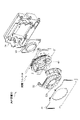
図2は、実施形態の演出装置20の分解斜視図である。
演出装置20は、表示窓9の上側Z2に配置される。演出装置20は、遊技中において、例えば、告知等に関する演出を行う装置である。
演出装置20は、前パネル21、装飾部22、表示部23、裏カバー24、開閉ユニット30を備える。
演出装置20は、前側から後側に向けて、前パネル21、装飾部22、開閉ユニット30、表示部23、裏カバー24の順に配置されている。
[Production device 20]
FIG. 2 is an exploded perspective view of the effect device 20 of the embodiment.
The effect device 20 is arranged above the display window 9 Z2. The effect device 20 is a device that performs effects related to, for example, notification during a game.
The effect device 20 includes a front panel 21, a decoration part 22, a display part 23, a back cover 24, and an opening/closing unit 30. - 特許庁
The effect device 20 is arranged in order of a front panel 21, a decoration part 22, an opening/closing unit 30, a display part 23, and a back cover 24 from the front side to the rear side.

前パネル21は、演出装置20の前側に配置されることにより、演出装置20の内部構造を外部から視認できないように目隠ししたりする。
装飾部22は、花びらの形状を模した装飾がされている。装飾部22は、ほぼ円形の開口部22aが設けられている。開閉ユニット30の遮蔽部材40(後述する)、及び表示部23の表示領域は、この開口部22aを通して視認できるようになっている。つまり、前側から見た状態で、開口部22aの大きさは、表示部23を視認可能な程度に大きい。また、装飾部22は、透光性を有する樹脂等により製作され、かつ、内部にLED等の発光部が設けられることにより、発光するようにしてもよい。
表示部23は、液晶表示装置等の表示装置を備える。なお、表示部23は、液晶表示装置に限定されず、種々の装置を用いることができる。表示部23は、例えば、デザインシートの図柄をバックライトによって視認可能な状態及び視認できない状態で変化するもの(例えば、特開2017-70415号公報に記載の表示ユニット)等を備えていてもよい。また、表示部23は、表示内容が変化するものではなく、例えば、固定の図柄等が印刷された印刷物等を備えていてもよい。この場合でも、遊技機1は、後述する開閉ユニット30の制御によって、図柄等が視認可能な状態及び視認できない状態で変化させることができる。
裏カバー24は、演出装置20を後側から保護するケースである。
The front panel 21 is arranged on the front side of the effect device 20 to hide the internal structure of the effect device 20 from the outside.
The decorative portion 22 is decorated in the shape of petals. The decorative portion 22 is provided with a substantially circular opening 22a. A shielding member 40 (described later) of the opening/closing unit 30 and a display area of the display unit 23 can be visually recognized through the opening 22a. That is, when viewed from the front side, the size of the opening 22a is large enough to allow the display section 23 to be visually recognized. Also, the decorative portion 22 may be made of a translucent resin or the like and provided with a light-emitting portion such as an LED inside to emit light.
The display unit 23 includes a display device such as a liquid crystal display device. Note that the display unit 23 is not limited to a liquid crystal display device, and various devices can be used. The display unit 23 may be provided with, for example, a display unit that changes the pattern of the design sheet between a visible state and a non-visible state with a backlight (for example, the display unit described in Japanese Patent Application Laid-Open No. 2017-70415). . In addition, the display unit 23 may be provided with a printed matter or the like on which a fixed pattern or the like is printed, instead of changing the display content. Even in this case, the game machine 1 can be changed between a visible state and a non-visible state by controlling the opening/closing unit 30, which will be described later.
The back cover 24 is a case that protects the effect device 20 from the rear side.

[開閉ユニット30]
図3は、開閉ユニット30を後側Y2から見た斜視図である。
図3(A)は、開閉ユニット30を組み立てた状態を示す図である。
図3(B)は、開閉ユニット30の分解斜視図である。
図4は、実施形態の開閉ユニット30を後側Y2から見た図である。
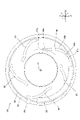
図5は、実施形態の5つの遮蔽部材40を前側Y1から見た図である。
図6は、実施形態の遮蔽部材40の1つを示す図である。
図6(A)は、遮蔽部材40を前側Y1から見た図である。
図6(B)は、遮蔽部材40の断面図(図6(A)、図6(C)のB-B断面図)である。
図6(C)は、遮蔽部材40を後側Y2から見た図である。
図6(D)は、遮蔽部材40を左側X1から見た図である。
図7は、実施形態の遮蔽部材40、保持部50を後側Y2から見た状態の位置関係を説明する図である。
図7(A)は、閉状態における位置関係を示す図である。
図7(B)は、開状態における位置関係を示す図である。
図8は、実施形態の回転板60を後側Y2から見た図である。
[Open/close unit 30]
FIG. 3 is a perspective view of the opening/closing unit 30 viewed from the rear side Y2.
FIG. 3A is a diagram showing a state in which the opening/closing unit 30 is assembled.
FIG. 3B is an exploded perspective view of the opening/closing unit 30. FIG.
FIG. 4 is a view of the opening/closing unit 30 of the embodiment viewed from the rear side Y2.
FIG. 5 is a view of five shielding members 40 of the embodiment viewed from the front side Y1.
FIG. 6 is a diagram showing one of the shielding members 40 of the embodiment.
FIG. 6A is a diagram of the shielding member 40 viewed from the front side Y1.
FIG. 6(B) is a cross-sectional view of the shielding member 40 (a cross-sectional view taken along the line BB in FIGS. 6(A) and 6(C)).
FIG. 6C is a view of the shielding member 40 viewed from the rear side Y2.
FIG. 6D is a diagram of the shielding member 40 viewed from the left side X1.
FIG. 7 is a diagram illustrating the positional relationship of the shielding member 40 and the holding portion 50 of the embodiment when viewed from the rear side Y2.
FIG. 7A is a diagram showing the positional relationship in the closed state.
FIG. 7B is a diagram showing the positional relationship in the open state.
FIG. 8 is a view of the rotating plate 60 of the embodiment viewed from the rear side Y2.

開閉ユニット30の説明、図面では、適宜、XYZ直交座標系を用いて説明する。この座標系は、遊技機1及び開閉ユニット30の各方向に対応しており、左右方向X(左側X1、右側X2)、前後方向Y(前側Y1、後側Y2)、鉛直方向Z(下側Z1、上側Z2)を表す。
開閉ユニット30は、遮蔽部材40を開閉駆動することにより、表示部23の表示領域を、遊技者に視認できる状態、視認できない状態の間で変化させる装置である。
図3に示すように、開閉ユニット30は、ベース31、遮蔽部材40、保持部50、回転板60(駆動部)、発光電力基板59、駆動ユニット70を備える。
遮蔽部材40、保持部50、回転板60、ベース31は、前側Y1から後側Y2に向けて、この順番で配置されている。保持部50及びベース31の間は、ベース31の外周に設けられたボスを用いてネジ固定されている。つまり、回転板60は、保持部50及びベース31の間に挟まれて配置されている。
遮蔽部材40、回転板60は、それぞれ、保持部50及びベース31に対して回転移動可能である。
The opening/closing unit 30 will be described using an XYZ orthogonal coordinate system as appropriate in the drawings. This coordinate system corresponds to each direction of the game machine 1 and the opening/closing unit 30, and includes a horizontal direction X (left side X1, right side X2), a front-back direction Y (front side Y1, rear side Y2), and a vertical direction Z (bottom side). Z1, upper Z2).
The opening/closing unit 30 is a device that changes the display area of the display unit 23 between a state visible to the player and a state invisible to the player by driving the shielding member 40 to open and close.
As shown in FIG. 3 , the opening/closing unit 30 includes a base 31 , a shielding member 40 , a holding section 50 , a rotating plate 60 (driving section), a light emitting power board 59 and a driving unit 70 .
The shield member 40, the holding portion 50, the rotating plate 60, and the base 31 are arranged in this order from the front side Y1 toward the rear side Y2. The holding portion 50 and the base 31 are screwed using bosses provided on the outer circumference of the base 31 . That is, the rotating plate 60 is sandwiched between the holding portion 50 and the base 31 .
The shielding member 40 and the rotating plate 60 are rotatable with respect to the holding portion 50 and the base 31, respectively.

ベース31、保持部50、回転板60は、それぞれ前後方向Yに貫通する円形の開口穴31a,50a,60aを備える。これらの開口穴31a,50a,60aの中心は、前後方向Yに平行な同一の軸上に位置する。実施形態では、この軸を、適宜、中心軸Cという。
前側Y1から見た状態で、保持部50、回転板60の開口穴50a,60aの大きさは、同等であり、また、表示部23の表示領域を視認可能な程度に大きい。
The base 31, the holding portion 50, and the rotary plate 60 are provided with circular opening holes 31a, 50a, and 60a penetrating in the front-rear direction Y, respectively. The centers of these opening holes 31a, 50a, 60a are located on the same axis parallel to the front-rear direction Y. As shown in FIG. In the embodiments, this axis is referred to as a central axis C as appropriate.
When viewed from the front side Y1, the opening holes 50a and 60a of the holding portion 50 and the rotating plate 60 are the same size, and are large enough to allow the display area of the display portion 23 to be visually recognized.

開閉ユニット30の各部材の詳細を説明する。
(ベース31)
ベース31は、開閉ユニット30の基部となる部材である。ベース31は、遊技機1の前扉2aに対して固定されている。
図4に示すように、ベース31は、検出部31b、ローラ31cを備える。
検出部31bは、後述するように、遮蔽部材40が閉位置に配置されたことを検出するセンサである。検出部31bは、例えば、発光素子及び受光素子が対向配置されたフォトインタラプタであり、回転板60に設けられた検出突起64(後述する)がこれらの素子の間に配置されたことを検出する。後側Y2から見た状態で、検出部31bは、開口穴31aの左上に配置されている。
Details of each member of the opening/closing unit 30 will be described.
(Base 31)
The base 31 is a member that serves as a base of the opening/closing unit 30 . The base 31 is fixed to the front door 2a of the game machine 1. As shown in FIG.
As shown in FIG. 4, the base 31 includes a detector 31b and rollers 31c.
The detection unit 31b is a sensor that detects that the shielding member 40 is placed at the closed position, as will be described later. The detection unit 31b is, for example, a photointerrupter in which a light emitting element and a light receiving element are arranged facing each other, and detects that a detection projection 64 (described later) provided on the rotating plate 60 is arranged between these elements. . The detection part 31b is arranged on the upper left of the opening hole 31a when viewed from the rear side Y2.

ローラ31cは、回転板60を回転可能に支持する。ローラ31cは、開口穴31aの外縁に複数設けられている。ローラ31cは、前後方向Yの軸回りに回転可能に支持される。開閉ユニット30が組み立てられた状態で、ローラ31cと、回転板60の外周リブ62(後述する)の外周面とは、接触する。これにより、ローラ31cは、回転板60を径方向の外側に移動しないように規制し、かつ、中心軸Cの軸回りに回転可能に支持する。 The roller 31c rotatably supports the rotating plate 60. As shown in FIG. A plurality of rollers 31c are provided on the outer edge of the opening hole 31a. The roller 31c is rotatably supported around an axis in the front-rear direction Y. As shown in FIG. When the opening/closing unit 30 is assembled, the roller 31c and the outer peripheral surface of the outer peripheral rib 62 (described later) of the rotating plate 60 come into contact with each other. Thereby, the roller 31c regulates the rotary plate 60 so that it does not move radially outward, and supports the rotary plate 60 so as to be rotatable around the central axis C. As shown in FIG.

(遮蔽部材40)
図3、図5に示すように、遮蔽部材40は、5つ設けられている。
遮蔽部材40は、閉位置及び開位置の間で、開閉駆動される。
なお、実施形態では、適宜、遮蔽部材40が閉位置に配置された状態(図5、図10(A)等参照)を開状態といい、開位置に配置された状態(図10(B)等参照)を開状態という。また、特定の遮蔽部材40を説明する場合には、適宜、アルファベットを付して遮蔽部材40A~40Eと示す。
5つの遮蔽部材40は、閉状態では、一体となることにより植物の花を模した立体形状を形成し(図5参照)、開状態では、花が分解するように駆動される(図2参照)。
花の形状の中央には、凹部40bを有する。凹部40b内は、人物の顔を模した造形処理がされている。
凹部40bよりも外側部分40cは、一段高くなっており、花びらを模した造形処理がされている。
5つの遮蔽部材40は、ベース31に対して回転することにより、中央部の開口部40aの大きさが変化する。これにより、遮蔽部材40は、表示部23の表示領域の可視範囲を変化させる(図10等参照)。
(Shielding member 40)
As shown in FIGS. 3 and 5, five shielding members 40 are provided.
The shielding member 40 is driven to open and close between the closed position and the open position.
In the embodiment, the state in which the shielding member 40 is arranged in the closed position (see FIGS. 5, 10A, etc.) is referred to as an open state, and the state in which the shielding member 40 is arranged in the open position (FIG. 10B). etc.) is called an open state. Also, when describing a specific shielding member 40, it will be denoted as shielding members 40A to 40E with alphabetical letters.
In the closed state, the five shielding members 40 are united to form a three-dimensional shape imitating the flower of a plant (see FIG. 5), and in the open state, they are driven so that the flower disassembles (see FIG. 2). ).
The center of the flower shape has a recess 40b. The interior of the concave portion 40b is shaped to resemble a person's face.
The outer portion 40c is one step higher than the recessed portion 40b, and is shaped to resemble a flower petal.
As the five shielding members 40 rotate with respect to the base 31, the size of the central opening 40a changes. Thereby, the shielding member 40 changes the visible range of the display area of the display unit 23 (see FIG. 10 and the like).

図6に示すように、遮蔽部材40は、ケース41(第1遮蔽部)、後板42(第2遮蔽部)、回転軸45a、中間支持軸45b、カムピン45c、発光部46を備える。
ケース41、後板42は、遮蔽部材40の外郭部材である。
ケース41は、後側Y2に開口した深底の容器状の部材である。ケース41は、例えば透明な樹脂等を射出成型等することにより製作できる。
As shown in FIG. 6, the shielding member 40 includes a case 41 (first shielding portion), a rear plate 42 (second shielding portion), a rotating shaft 45a, an intermediate support shaft 45b, a cam pin 45c, and a light emitting portion 46.
The case 41 and rear plate 42 are outer shell members of the shielding member 40 .
The case 41 is a deep-bottomed container-like member that opens on the rear side Y2. The case 41 can be manufactured, for example, by injection molding a transparent resin or the like.

ケース41には、透光性を有さない塗料で塗装後に、透光性を有する金属メッキでメッキ処理がされている。
図5に示すように、遮蔽部材40Bのケース表面の一部は、塗装がされていない抜き部41a(図5参照)である。抜き部41aは、二次元の図形、文字等である。実施形態では、抜き部41aは、人物の額に対応した位置に配置され、矢印の形状の内部に記号が設けられている。このため、ケース41は、通常時(発光部46が発光動作していない状態)には金属光沢を有し、発光部46の発光時には抜き部41aのみが光るようになっている。
The case 41 is coated with non-translucent paint and then plated with translucent metal plating.
As shown in FIG. 5, part of the surface of the case of the shielding member 40B is an unpainted cut-out portion 41a (see FIG. 5). The cut-out portion 41a is a two-dimensional figure, character, or the like. In the embodiment, the cut-out portion 41a is arranged at a position corresponding to the person's forehead, and a symbol is provided inside the shape of an arrow. Therefore, the case 41 normally has a metallic luster (when the light emitting unit 46 does not emit light), and when the light emitting unit 46 emits light, only the cut-out portion 41a shines.

遮蔽部材40A,40C~40Eのケース41には、透光部41b,41cが埋め込まれている。
透光部41b,41cは、例えば透明な樹脂等を射出成型等することにより製作できる。
透光部41bは、メガネを模した形状である。透光部41bは、ケース41の抜き部41aと同様に、金属メッキの処理がされている。このため、透光部41bも、通常時には金属光沢を有し、発光時には光る。透光部41bの金属光沢の色彩と、ケース41の金属光沢とは、異なっている。このため、通常時においても、透光部41bの形状を、メガネの形状として認識できる。
透光部41cは、唇を模した形状である。透光部41cは、透光部41bとは異なりメッキ等の表面処理がされていない。但し、透光部41cの表面は、凹凸の造形処理、梨地加工等がされている。このため、透光部41cは、通常時には光らず、かつ、ケース41内部の構造が視認できないようになっており、発光時には光る。
Translucent portions 41b and 41c are embedded in the cases 41 of the shielding members 40A, 40C to 40E.
The translucent portions 41b and 41c can be manufactured by, for example, injection molding a transparent resin or the like.
The translucent part 41b has a shape that imitates glasses. The translucent portion 41b is plated with metal, like the cutout portion 41a of the case 41. As shown in FIG. Therefore, the translucent portion 41b also has a metallic luster in normal times, and shines in light emission. The color of the metallic luster of the translucent portion 41b and the metallic luster of the case 41 are different. Therefore, even in normal times, the shape of the translucent portion 41b can be recognized as the shape of the glasses.
The translucent portion 41c has a lip-like shape. Unlike the translucent portion 41b, the translucent portion 41c is not subjected to surface treatment such as plating. However, the surface of the light-transmitting portion 41c is subjected to an uneven shaping process, a satin finish, or the like. For this reason, the translucent part 41c does not shine normally, and the structure inside the case 41 cannot be visually recognized, and it shines during light emission.

上記構成により、ケース41は、閉状態では、通常時にはメガネ及び唇によって人のイラストを視認でき、発光時にはメガネ、唇、額が光るように演出できる。 With the above configuration, when the case 41 is closed, the illustration of a person can be seen through the glasses and the lips in a normal state, and when the case 41 emits light, the glasses, the lips, and the forehead can be illuminated.

図6に示すように、後板42は、ケース41の後側Y2に配置され、ケース41に対してネジ固定される。つまり、後板42は、ケース41よりも後側Y2(つまり表示部23側)に配置されている。前後方向Yから見た状態で、後板42の外形は、ケース41の外形よりも、大きい。これにより、ケース41の開口は、蓋をされる。
後板42は、凹部42a、凸部42b、コネクタ穴42cを備える。
凹部42a、凸部42bは、後板42の後面に設けられる。つまり、後板42の後面は、凹凸形状に形成されている。
コネクタ穴42cは、LED基板46a及び発光電力基板59間を接続するケーブル47(図7参照)を挿通する穴である。コネクタ穴42cには、LED基板46aに実装されたコネクタ46bが露出する(図6(D)の一部断面(二点鎖線内)参照)。
As shown in FIG. 6, the rear plate 42 is arranged on the rear side Y2 of the case 41 and fixed to the case 41 with screws. That is, the rear plate 42 is arranged on the rear side Y2 (that is, the display section 23 side) of the case 41 . The outer shape of the rear plate 42 is larger than the outer shape of the case 41 when viewed in the front-rear direction Y. - 特許庁Thereby, the opening of the case 41 is covered.
The rear plate 42 has a concave portion 42a, a convex portion 42b, and a connector hole 42c.
The concave portion 42 a and the convex portion 42 b are provided on the rear surface of the rear plate 42 . That is, the rear surface of the rear plate 42 is formed in an uneven shape.
The connector hole 42c is a hole through which a cable 47 (see FIG. 7) connecting between the LED board 46a and the light emitting power board 59 is inserted. The connector 46b mounted on the LED substrate 46a is exposed through the connector hole 42c (see the partial cross section (inside the two-dot chain line) in FIG. 6D).

回転軸45a、中間支持軸45b、カムピン45cは、後板42の後面に固定された軸体である。回転軸45a、中間支持軸45bは、後板42の後面から後側Y2に突出するように設けられており、各軸方向と中心軸Cの方向とは、平行である。
回転軸45aは、保持部50に軸支される。
中間支持軸45bは、保持部50の中間支持穴55b(図7参照)内を移動可能に、保持部50に支持される。
カムピン45cは、回転板60のカム穴66(図8参照)内を移動可能に、回転板60に支持される。つまり、開閉ユニット30は、カム部として、カムピン45c及び回転板60のカム穴66を備える。カムピン45cの外周には、Eリングを取り付けるための溝が設けられている。
The rotary shaft 45a, the intermediate support shaft 45b, and the cam pin 45c are shaft bodies fixed to the rear surface of the rear plate 42. As shown in FIG. The rotation shaft 45a and the intermediate support shaft 45b are provided so as to protrude from the rear surface of the rear plate 42 to the rear side Y2, and the direction of each axis and the direction of the central axis C are parallel.
The rotating shaft 45 a is pivotally supported by the holding portion 50 .
The intermediate support shaft 45b is supported by the holding portion 50 so as to be movable within the intermediate support hole 55b (see FIG. 7) of the holding portion 50. As shown in FIG.
The cam pin 45c is supported by the rotary plate 60 so as to be movable in a cam hole 66 (see FIG. 8) of the rotary plate 60. As shown in FIG. That is, the opening/closing unit 30 includes the cam pin 45c and the cam hole 66 of the rotating plate 60 as the cam portion. A groove for mounting an E-ring is provided on the outer periphery of the cam pin 45c.

このように、遮蔽部材40は、3つの軸体45a,45b,45cによって、支持されながら開閉駆動される。すなわち、遮蔽部材40は、回転軸45a及びカムピン45cに加えて、これらの間に配置された中間支持軸45bを用いて保持される。これにより、遮蔽部材40は、発光部46を収容する程度の厚さを有していても、十分な強度で保持される。 Thus, the shielding member 40 is driven to open and close while being supported by the three shafts 45a, 45b, and 45c. In other words, the shielding member 40 is held using the rotation shaft 45a and the cam pin 45c as well as the intermediate support shaft 45b arranged therebetween. As a result, the shielding member 40 is held with sufficient strength even if it has a thickness sufficient to accommodate the light emitting section 46 .

図6に示すように、発光部46は、ケース41の内部に収容されている。
発光部46は、LED基板46a、コネクタ46b、LED46cを備える。
LED基板46aは、電気基板である。LED基板46aは、ケース41に対して、ネジ止め等により固定されている。LED基板46aの前面には、コネクタ46b、複数のLED46cが実装されている。
コネクタ46bは、LED基板46a及び発光電力基板59間を接続するケーブル47が接続される。コネクタ46bは、サイド接続型のものであり、LED基板46aの縁部に配置されている。これにより、コネクタ46bは、後板42のコネクタ穴42cに露出するように配置できる。
LED46cは、LED基板46aの前面に実装されている。このため、LED46cは、前側Y1に向けて光を発光する。これにより、LED46cは、抜き部41a、透光部41b,41cを光らせることができる。また、複数のLED46cは、互い異なる発色であってもよく、また、各LED46cは、多色に発色可能であってもよい。この場合には、遊技機1は、発光するLED46cを変えたり、各LED46cの発色を変えることにより、華やかに演出できる。
As shown in FIG. 6, the light emitting part 46 is housed inside the case 41 .
The light emitting unit 46 includes an LED board 46a, a connector 46b, and an LED 46c.
The LED board 46a is an electric board. The LED board 46a is fixed to the case 41 by screws or the like. A connector 46b and a plurality of LEDs 46c are mounted on the front surface of the LED board 46a.
A cable 47 connecting between the LED board 46a and the light emitting power board 59 is connected to the connector 46b. The connector 46b is of a side connection type and is arranged at the edge of the LED substrate 46a. Thereby, the connector 46b can be arranged so as to be exposed to the connector hole 42c of the rear plate 42. As shown in FIG.
The LED 46c is mounted on the front surface of the LED substrate 46a. Therefore, the LED 46c emits light toward the front side Y1. Thereby, the LED 46c can illuminate the cut-out portion 41a and the translucent portions 41b and 41c. Further, the plurality of LEDs 46c may emit colors different from each other, and each LED 46c may emit multiple colors. In this case, the game machine 1 can perform gorgeously by changing the emitting LED 46c or changing the color of each LED 46c.

(保持部50)
保持部50は、遮蔽部材40、回転板60を回転可能に保持する部材である。
図3に示すように、保持部50は、円盤状の円盤部51と、円環状の円環部52とが、ネジ等(図示せず)で固定されて構成される。保持部50は、外縁部に設けられたボスを利用して、ベース31にネジ固定される。
(Holding portion 50)
The holding part 50 is a member that rotatably holds the shielding member 40 and the rotating plate 60 .
As shown in FIG. 3, the holding portion 50 is configured by fixing a disk-shaped disk portion 51 and an annular ring portion 52 with screws or the like (not shown). The holding part 50 is screwed to the base 31 using bosses provided on the outer edge.

保持部50は、遮蔽部材保持部55、ケーブル挿通穴56、ローラ57を備える。
図3、図7に示すように、遮蔽部材保持部55は、遮蔽部材40を保持する部分である。
遮蔽部材保持部55は、5つの遮蔽部材40に対応して5つ設けられている。
図7は、5つの遮蔽部材保持部55のうち1つの構成を図示するが、他の遮蔽部材40も同様な構成である。
The holding portion 50 includes a shielding member holding portion 55 , cable insertion holes 56 and rollers 57 .
As shown in FIGS. 3 and 7 , the shielding member holding portion 55 is a portion that holds the shielding member 40 .
Five shielding member holding portions 55 are provided corresponding to the five shielding members 40 .
Although FIG. 7 illustrates the configuration of one of the five shielding member holding portions 55, the other shielding member 40 has a similar configuration.

遮蔽部材保持部55は、回転軸支持穴55a、中間支持穴55b、カムピン挿通穴55cを備える。
回転軸支持穴55a、中間支持穴55b、カムピン挿通穴55cは、保持部50を前後方向Yに貫通する穴である。回転軸支持穴55a、中間支持穴55b、カムピン挿通穴55cは、それぞれ、遮蔽部材40の回転軸45a、中間支持軸45b、カムピン45cが挿入されている。各穴55a~55cと、各軸体45a~45cとは、それぞれ、プーリ等を介して、回転、摺動等可能に接続されている。
回転軸支持穴55aは、遮蔽部材40の回転軸45aを軸支する。これにより、遮蔽部材40は、回転軸支持穴55aを中心に回転する。
The shielding member holding portion 55 includes a rotating shaft support hole 55a, an intermediate support hole 55b, and a cam pin insertion hole 55c.
The rotating shaft support hole 55a, the intermediate support hole 55b, and the cam pin insertion hole 55c are holes penetrating the holding portion 50 in the front-rear direction Y. As shown in FIG. The rotary shaft 45a, the intermediate support shaft 45b, and the cam pin 45c of the shielding member 40 are inserted into the rotary shaft support hole 55a, the intermediate support hole 55b, and the cam pin insertion hole 55c, respectively. The holes 55a to 55c and the shaft bodies 45a to 45c are connected to each other via pulleys or the like so as to be rotatable, slidable, or the like.
The rotating shaft support hole 55a supports the rotating shaft 45a of the shielding member 40. As shown in FIG. As a result, the shielding member 40 rotates around the rotation shaft support hole 55a.

中間支持穴55b、カムピン挿通穴55cは、円弧状の穴であり、それぞれ回転軸支持穴55aを中心とした円周上に設けられている。各穴55b,55cの円弧の形状は、遮蔽部材40の回転にともなう各軸体45b,45cの移動軌跡に対応している。
このため、カムピン挿通穴55cの半径の方が、中間支持穴55bの半径よりも大きい。
The intermediate support hole 55b and the cam pin insertion hole 55c are arc-shaped holes, and are provided on the circumference centered on the rotary shaft support hole 55a. The arc shapes of the holes 55b and 55c correspond to the locus of movement of the shafts 45b and 45c as the shielding member 40 rotates.
Therefore, the radius of the cam pin insertion hole 55c is larger than the radius of the intermediate support hole 55b.

ケーブル挿通穴56は、発光電力基板59(図3参照)及びLED基板46a間を接続するケーブル47を挿通する穴である。
図7に示すように、後側Y2から見た状態で、ケーブル挿通穴56の大きさは、遮蔽部材40のコネクタ穴42cの大きさよりも大きい。また、遮蔽部材40が閉位置、開位置に配置された状態と、両位置の間で変位している状態とにおいて、ケーブル挿通穴56には、常に、コネクタ穴42cが露出する。また、ケーブル挿通穴56は、回転軸支持穴55aの近傍に配置されているので、遮蔽部材40の開閉時における回転半径が小さい。
これにより、LED基板46a及び発光電力基板59間を接続するケーブル47は、大きなストレスがかからない。また、遮蔽部材40を保持部50に取り付け後においても、ケーブル47は、ケーブル挿通穴56、コネクタ穴42cを通して、LED基板46aのコネクタ46bに接続することができる。
The cable insertion hole 56 is a hole through which the cable 47 connecting between the light emitting power board 59 (see FIG. 3) and the LED board 46a is inserted.
As shown in FIG. 7, the size of the cable insertion hole 56 is larger than the size of the connector hole 42c of the shielding member 40 when viewed from the rear side Y2. Further, the connector hole 42c is always exposed in the cable insertion hole 56 when the shielding member 40 is arranged at the closed position, the open position, and when the shielding member 40 is displaced between the two positions. Further, since the cable insertion hole 56 is arranged in the vicinity of the rotating shaft support hole 55a, the radius of rotation when the shielding member 40 is opened and closed is small.
As a result, the cable 47 connecting between the LED board 46a and the light-emitting power board 59 is not subjected to a large amount of stress. Even after the shielding member 40 is attached to the holding portion 50, the cable 47 can be connected to the connector 46b of the LED board 46a through the cable insertion hole 56 and the connector hole 42c.

図3に示すように、ローラ57は、回転板60を回転可能に保持する。ローラ57は、円環部52に複数設けられ、回転板60のつば部63を前面から支える。ローラ57の回転軸は、中心軸Cに直交する方向であり、ローラ57の回転方向は、回転板60のつば部63の周方向に平行である。これにより、ローラ57は、回転板60を前側Y1に移動しないように規制し、かつ、回転板60を回転可能に支持する。 As shown in FIG. 3, rollers 57 rotatably hold rotating plate 60 . A plurality of rollers 57 are provided on the annular portion 52 and support the flange portion 63 of the rotary plate 60 from the front surface. The rotation axis of the roller 57 is perpendicular to the central axis C, and the rotation direction of the roller 57 is parallel to the circumferential direction of the flange portion 63 of the rotary plate 60 . Thereby, the roller 57 regulates the rotary plate 60 so as not to move to the front side Y1, and supports the rotary plate 60 rotatably.

図3に示すように、発光電力基板59は、円盤部51の後面に、ネジ止め等によって固定される。発光電力基板59は、発光部46に電力を供給する電気基板である。図3には、発光電力基板59は、板材59aで保護された例を図示する。
前後方向Y(つまり駆動部の回転軸方向)において、発光電力基板59は、遮蔽部材40及び回転板60の間に配置される。また、発光電力基板59は、中心軸Cに直交する平面(XY平面)内においてカムピン45cの移動範囲外に配置されている。つまり、発光電力基板59は、回転軸支持穴55a、中間支持穴55b、カムピン挿通穴55cの範囲外に配置される。これにより、前後方向Yから見た状態で、発光電力基板59は、カムピン45c等と干渉することなく、回転板60の外形よりも内側に配置できる。
As shown in FIG. 3, the light-emitting power board 59 is fixed to the rear surface of the disc portion 51 by screwing or the like. The light-emitting power board 59 is an electric board that supplies power to the light-emitting section 46 . FIG. 3 shows an example in which the light-emitting power board 59 is protected by a plate member 59a.
The light-emitting power board 59 is arranged between the shielding member 40 and the rotating plate 60 in the front-rear direction Y (that is, the rotation axis direction of the drive unit). In addition, the light-emitting power board 59 is arranged outside the movement range of the cam pin 45c within a plane (XY plane) orthogonal to the central axis C. As shown in FIG. That is, the light-emitting power board 59 is arranged outside the range of the rotating shaft support hole 55a, the intermediate support hole 55b, and the cam pin insertion hole 55c. As a result, when viewed from the front-rear direction Y, the light-emitting power board 59 can be arranged inside the outer shape of the rotating plate 60 without interfering with the cam pin 45c or the like.

(回転板60)
回転板60は、回転駆動されることにより、遮蔽部材40を回転移動させる部材である。
図3、図8に示すように、回転板60の形状は、円盤状である。
回転板60の回転軸(回転の中心軸)と、中心軸Cとは、同心である。
回転板60は、外周リブ61,62、つば部63、検出突起64、歯車65、カム穴66、ローラ68を備える。
外周リブ61,62は、回転板60の前面の外周部、後面の外周部にそれぞれ設けられた円環状のリブである。
つば部63は、外周リブ61,62よりも外側にフランジ状に突出する部分である。
検出突起64は、検出部31bが回転板60の回転位置を検出するために設けられた突起である。
歯車65は、回転板60を回転するための平歯車である。歯車65は、回転板60の外周の一部に沿って設けられている。
(Rotating plate 60)
The rotating plate 60 is a member that rotates the shielding member 40 by being rotationally driven.
As shown in FIGS. 3 and 8, the shape of the rotating plate 60 is disc-shaped.
The rotation axis (the central axis of rotation) of the rotating plate 60 and the central axis C are concentric.
The rotary plate 60 includes outer peripheral ribs 61 and 62 , a flange portion 63 , a detection protrusion 64 , a gear 65 , a cam hole 66 and rollers 68 .
The outer peripheral ribs 61 and 62 are annular ribs provided on the outer peripheral portion of the front surface and the outer peripheral portion of the rear surface of the rotary plate 60, respectively.
The flange portion 63 is a portion that protrudes outward from the outer peripheral ribs 61 and 62 in a flange shape.
The detection protrusion 64 is a protrusion provided for detecting the rotational position of the rotating plate 60 by the detection section 31b.
A gear 65 is a spur gear for rotating the rotary plate 60 . A gear 65 is provided along a portion of the outer circumference of the rotating plate 60 .

カム穴66は、遮蔽部材40の5つのカムピン45cに対応して、5つ設けられている。カム穴66は、回転板60を前後方向Yに貫通する長穴である。
カム穴66は、カムピン45cが挿入されている(図4等参照)。カムピン45cは、Eリング、プーリ、ネジ等によって、カム穴66に接続されている。つまり、カム穴66及びカムピン45cは、係合している。
後述するように、カムピン45cがカム穴66内を移動することに応じて、遮蔽部材40が開閉する。
前後方向Yから見た状態で、各カムピン45cは、内円弧穴66a(回転位置維持部)、変化部66b、外円弧穴66c(回転位置維持部)を備え、これらが内側から外側に向けて連続している。
内円弧穴66aは、中心軸Cと同心の円周67a上の一部に設けられている。
変化部66bは、外側かつ右回りに至るほど、半径が徐々に大きくなるような形状である。
外円弧穴66cは、中心軸Cと同心の円周67c上の一部に設けられている。円周67cの径は、円周67aの径よりも大きい。
Five cam holes 66 are provided corresponding to the five cam pins 45 c of the shielding member 40 . The cam hole 66 is an elongated hole penetrating the rotary plate 60 in the front-rear direction Y. As shown in FIG.
The cam pin 45c is inserted into the cam hole 66 (see FIG. 4, etc.). The cam pin 45c is connected to the cam hole 66 by an E-ring, pulley, screw or the like. That is, the cam hole 66 and the cam pin 45c are engaged.
As will be described later, the shielding member 40 opens and closes as the cam pin 45c moves within the cam hole 66. As shown in FIG.
Each cam pin 45c has an inner circular arc hole 66a (rotational position maintaining portion), a changing portion 66b, and an outer circular arc hole 66c (rotational position maintaining portion) when viewed from the front-rear direction Y. Contiguous.
The inner circular arc hole 66a is provided on a part of a circumference 67a concentric with the center axis C. As shown in FIG.
The changing portion 66b has a shape in which the radius gradually increases toward the outside and clockwise.
The outer arc hole 66c is provided on a part of the circumference 67c concentric with the center axis C. As shown in FIG. The diameter of the circumference 67c is larger than the diameter of the circumference 67a.

図3の一部の断面に示すように、ローラ68は、外周リブ61の外周面に設けられている。詳細な図示は、省略するが、ローラ68は、外周リブ61に複数設けられている。ローラ68の回転軸と、中心軸Cとは、平行である。ローラ68は、保持部50の円環部52の内周面に接触する。
このように、回転板60は、径方向において、外周リブ62及びベース31のローラ31cに支持されることに加えて(図4等参照)、ローラ68及び保持部50の円環部52に支持される。これにより、回転板60は、鉛直面方向(ZX平面内)において、精度よく位置決めされ、かつ、回転時の偏心を抑制できる。
As shown in the partial cross section of FIG. 3 , the rollers 68 are provided on the outer peripheral surface of the outer peripheral rib 61 . Although detailed illustration is omitted, a plurality of rollers 68 are provided on the outer peripheral rib 61 . The rotation axis of the roller 68 and the central axis C are parallel. The roller 68 contacts the inner peripheral surface of the annular portion 52 of the holding portion 50 .
Thus, the rotating plate 60 is supported in the radial direction by the outer peripheral rib 62 and the rollers 31c of the base 31 (see FIG. 4 etc.), and also supported by the rollers 68 and the annular portion 52 of the holding portion 50. be done. As a result, the rotating plate 60 can be accurately positioned in the vertical plane direction (within the ZX plane), and eccentricity during rotation can be suppressed.

(駆動ユニット70)
駆動ユニット70は、回転板60を回転駆動するためのユニットである。
図3、図4に示すように、駆動ユニット70は、後側Y2から見た状態で、回転板60の直近であって、回転板60よりも左上の範囲に設けられている。
駆動ユニット70は、モータ71、歯車72,73、カバー74、駆動基板75を備える。なお、図4は、カバー74、駆動基板75を取り外した状態を図示した。
モータ71の回転軸と、各歯車72,73の回転軸と、中心軸Cとは、平行である。
(Drive unit 70)
The drive unit 70 is a unit for driving the rotating plate 60 to rotate.
As shown in FIGS. 3 and 4, the drive unit 70 is provided in the immediate vicinity of the rotating plate 60 and in the upper left range of the rotating plate 60 when viewed from the rear side Y2.
The drive unit 70 includes a motor 71 , gears 72 and 73 , a cover 74 and a drive board 75 . Note that FIG. 4 illustrates a state in which the cover 74 and the drive board 75 are removed.
The rotating shaft of the motor 71, the rotating shafts of the gears 72 and 73, and the central axis C are parallel.

モータ71は、駆動ユニット70の駆動力を発生する駆動源であり、例えばDCステップモータ等である。モータ71の回転軸には、歯車71aが設けられている。
歯車71a,72,73は、平歯車である。
歯車72は、回転板60の歯車65と噛み合っている。
歯車73は、モータ71の歯車71aと、歯車72の間に設けられた遊び歯車である。
図3に示すように、カバー74は、歯車71a,72,73を後側Y2から保護する板状の部材である。カバー74の前側Y1には、モータ71、駆動基板75が配置されている。
駆動基板75は、ケーブル(図示せず)により、モータ71に電気的に接続されており、モータ71に電力を供給する。また、駆動基板75は、ケーブル(図示せず)により、副制御基板12に電気的に接続されている。また、駆動基板75は、検出部31bとの間を、電気ケーブルで接続されていてもよい。
The motor 71 is a drive source that generates driving force for the drive unit 70, and is, for example, a DC step motor. The rotating shaft of the motor 71 is provided with a gear 71a.
The gears 71a, 72, 73 are spur gears.
Gear 72 meshes with gear 65 of rotating plate 60 .
The gear 73 is an idle gear provided between the gear 71 a of the motor 71 and the gear 72 .
As shown in FIG. 3, the cover 74 is a plate-like member that protects the gears 71a, 72, 73 from the rear side Y2. A motor 71 and a drive board 75 are arranged on the front side Y1 of the cover 74 .
The drive board 75 is electrically connected to the motor 71 by a cable (not shown) and supplies power to the motor 71 . Also, the drive board 75 is electrically connected to the sub-control board 12 by a cable (not shown). Further, the drive board 75 may be connected to the detection section 31b by an electric cable.

上記構成により、駆動ユニット70は、制御部の命令に応じて、モータ71を回転させる。また、モータ71の駆動力を歯車71a,73,72を介して、回転板60の歯車65に伝達することにより、回転板60を回転することができる。 With the above configuration, the drive unit 70 rotates the motor 71 according to the command from the control section. Further, by transmitting the driving force of the motor 71 to the gear 65 of the rotating plate 60 via the gears 71a, 73, 72, the rotating plate 60 can be rotated.

また、駆動基板75は、モータ71の近傍に配置されているので、装置を小型にすることができる。さらに、駆動基板75は、歯車71a,72,73の後側Y2を覆うように配置されているので(図3(A)参照)、開閉ユニット30は、駆動に関する構成を一カ所にまとめて配置できるので、ユニットを小型にできる。
さらに、前述した検出部31bも、駆動ユニット70と同様に、回転板60の直近であって、回転板60よりも左上の範囲に設けられている。このため、駆動ユニット70及び駆動ユニット70の制御に利用される検出部31bは、近傍に配置されている。これにより、開閉ユニット30は、駆動に関する構成に加えて、その制御に利用される構成を、一カ所にまとめて配置できるので、ユニットをより進んで小型にできる。
Further, since the drive board 75 is arranged near the motor 71, the size of the device can be reduced. Furthermore, since the drive board 75 is arranged so as to cover the rear side Y2 of the gears 71a, 72, 73 (see FIG. 3A), the opening/closing unit 30 arranges the drive-related components in one place. Therefore, the unit can be made smaller.
Furthermore, like the drive unit 70 , the detection unit 31 b described above is also provided in the immediate vicinity of the rotary plate 60 and in the upper left range of the rotary plate 60 . Therefore, the driving unit 70 and the detecting section 31b used for controlling the driving unit 70 are arranged in the vicinity. As a result, in the opening/closing unit 30, in addition to the configuration related to driving, the configuration used for the control can be arranged together in one place, so that the unit can be made more compact.

[遮蔽部材40の開閉駆動]
遮蔽部材40の開閉駆動について詳細に説明する。
図9は、実施形態の検出部31b、遮蔽部材40、回転板60を後側Y2から見た状態における位置関係を説明する図である。
図9(A)は、閉状態の位置関係を示す図である。
図9(B)は、開状態の位置関係を示す図である。
[Opening/Closing Drive of Shielding Member 40]
The opening/closing drive of the shielding member 40 will be described in detail.
FIG. 9 is a diagram illustrating the positional relationship of the detection unit 31b, the shielding member 40, and the rotating plate 60 of the embodiment when viewed from the rear side Y2.
FIG. 9A is a diagram showing the positional relationship in the closed state.
FIG. 9B is a diagram showing the positional relationship in the open state.

(閉状態から開状態への開駆動)
最初に、遮蔽部材40を閉状態から開状態へと開駆動する例を説明する。
制御部は、遊技状態に応じて、駆動ユニット70の開駆動の制御を開始する。
図9(A)に示すように、制御部は、モータ71を制御することにより、回転板60を回転駆動する。
これに応じて、カムピン45cは、カム穴66内を移動する。カムピン45cは、3つの内円弧穴66a、変化部66b、外円弧穴66cを順に移動する。遮蔽部材40は、これらの3つの穴部に対応して、以下のように動作する。
(1)内円弧穴66a
内円弧穴66aは、回転板60の回転軸である中心軸Cと同心の円弧上に位置する。このため、カムピン45cは、内円弧穴66a内を移動する場合には、ベース31に対して移動しない。このため、遮蔽部材40は、回転することなく、閉位置を維持する。
(Open drive from closed state to open state)
First, an example of driving the shielding member 40 from the closed state to the open state will be described.
The control section starts controlling the drive unit 70 to open according to the game state.
As shown in FIG. 9A, the control section drives the rotating plate 60 to rotate by controlling the motor 71 .
Accordingly, the cam pin 45c moves within the cam hole 66. As shown in FIG. The cam pin 45c sequentially moves through the three inner arc holes 66a, the transition portion 66b, and the outer arc hole 66c. The shielding member 40 operates as follows corresponding to these three holes.
(1) Inner arc hole 66a
The inner arc hole 66 a is positioned on an arc concentric with the central axis C, which is the rotation axis of the rotary plate 60 . Therefore, the cam pin 45c does not move with respect to the base 31 when moving inside the inner circular arc hole 66a. Therefore, the shielding member 40 maintains the closed position without rotating.

(2)変化部66b
変化部66bの形状は、外側かつ右回りに至る程、中心軸Cからの距離が大きくなる。このため、カムピン45cが変化部66b内に位置する状態で、回転板60が左回りに回転すると、カムピン45cは、ベース31に対して径方向の外側に移動する。
これに応じて、遮蔽部材40は、回転軸45a回りに回転することにより、閉位置から開位置へと回転移動を開始する(図9(A)の矢印θ1参照)。
そして、カムピン45cが外円弧穴66cに到達することに応じて、遮蔽部材40は、開位置に配置される。
(2) Change portion 66b
As for the shape of the changing portion 66b, the distance from the central axis C increases toward the outside and clockwise. Therefore, when the rotary plate 60 rotates counterclockwise with the cam pin 45c positioned within the changing portion 66b, the cam pin 45c moves outward in the radial direction with respect to the base 31. As shown in FIG.
In response to this, the shielding member 40 rotates around the rotation shaft 45a, thereby starting to rotate from the closed position to the open position (see arrow θ1 in FIG. 9A).
When the cam pin 45c reaches the outer circular arc hole 66c, the shielding member 40 is arranged at the open position.

(3)外円弧穴66c
図9(B)に示すように、外円弧穴66cは、内円弧穴66aと同様に、中心軸Cと同心の円弧上に位置するので、カムピン45cは、内円弧穴66a内を移動する場合には、ベース31に対して移動しない。このため、カムピン45cは、変化部66bから外円弧穴66cに到達後には、ベース31に対して移動しない。
これにより、遮蔽部材40は、回転移動を停止する。
また、カムピン45cが内円弧穴66aに到達することに応じて、検出突起64が検出部31bに検出される。
検出部31bは、突出部の検出に基づいて検出信号を制御部に出力し、制御部は、これに応じて、モータ71の駆動を停止する。
(3) Outer arc hole 66c
As shown in FIG. 9B, the outer arc hole 66c is positioned on an arc concentric with the central axis C, like the inner arc hole 66a. , does not move relative to the base 31. Therefore, the cam pin 45c does not move with respect to the base 31 after reaching the outer arc hole 66c from the changing portion 66b.
As a result, the shielding member 40 stops rotating.
Further, when the cam pin 45c reaches the inner circular arc hole 66a, the detection projection 64 is detected by the detection portion 31b.
The detection unit 31b outputs a detection signal to the control unit based on the detection of the projecting portion, and the control unit stops driving the motor 71 accordingly.

ここで、回転板60が停止する場合には、歯車71a,72,73のバックラッシュ、オーバシュート等に起因して、停止位置の誤差等が発生することがある。
このような誤差等がある場合でも、カムピン45cの移動範囲が外円弧穴66c内であれば、遮蔽部材40は、開位置を維持できる。
Here, when the rotating plate 60 stops, an error or the like in the stop position may occur due to backlash, overshoot, or the like of the gears 71a, 72, and 73. FIG.
Even if there is such an error, the shield member 40 can maintain the open position as long as the movement range of the cam pin 45c is within the outer circular arc hole 66c.

(開状態から閉状態への閉駆動)
開状態から閉状態への駆動は、上記閉状態から開状態への駆動とは、逆の制御を行う。
すなわち、制御部は、カムピン45cの移動範囲に対応した分だけモータ71をパルス駆動することにより、回転板60を右回りに回転移動する。
これに応じて、カムピン45cは、カム穴66内を移動する。カムピン45cは、3つの外円弧穴66c、変化部66b、内円弧穴66aを順に移動する。遮蔽部材40は、これらの3つの穴部に対応して、以下のように動作する。
(1)外円弧穴66c
図9(B)に示すように、カムピン45cが外円弧穴66c内を移動している間は、遮蔽部材40は、開駆動時と同様に、開状態を維持する。
(2)変化部66b
カムピン45cが外円弧穴66cから変化部66bに到達後には、遮蔽部材40は、次回位置から閉位置に向けて、回転軸45a回りの回転移動を開始する。
図9(A)に示すように、そして、カムピン45cが内円弧穴66aに到達することに応じて、遮蔽部材40は、閉位置に配置される。
(3)内円弧穴66a
カムピン45cが内円弧穴66a内を移動している間、遮蔽部材40は、開駆動時と同様に、閉状態を維持する。
また、カムピン45cが内円弧穴66aに到達すると、制御部は、モータ71のパルス駆動を停止する。閉駆動時も開駆動時と同様に、停止位置の誤差等が発生しても、カムピン45cの移動範囲が内円弧穴66a内であれば、遮蔽部材40は、閉位置を維持できる。
(Close drive from open state to closed state)
The drive from the open state to the closed state performs control opposite to the drive from the closed state to the open state.
That is, the control unit rotates the rotary plate 60 clockwise by pulse-driving the motor 71 by an amount corresponding to the movement range of the cam pin 45c.
Accordingly, the cam pin 45c moves within the cam hole 66. As shown in FIG. The cam pin 45c sequentially moves through the three outer arc holes 66c, the transition portion 66b, and the inner arc hole 66a. The shielding member 40 operates as follows corresponding to these three holes.
(1) Outer arc hole 66c
As shown in FIG. 9B, while the cam pin 45c is moving inside the outer arcuate hole 66c, the shielding member 40 maintains the open state in the same manner as during the open drive.
(2) Change portion 66b
After the cam pin 45c reaches the changing portion 66b from the outer circular arc hole 66c, the shielding member 40 starts rotating about the rotation shaft 45a from the next position toward the closed position.
As shown in FIG. 9A and in response to the cam pin 45c reaching the inner circular arc hole 66a, the shielding member 40 is placed in the closed position.
(3) Inner arc hole 66a
While the cam pin 45c is moving inside the inner circular arc hole 66a, the shielding member 40 maintains the closed state in the same manner as during the open drive.
Further, when the cam pin 45c reaches the inner circular arc hole 66a, the control section stops the pulse driving of the motor 71. As shown in FIG. During the closing drive as well as during the opening drive, the shielding member 40 can maintain the closed position as long as the movement range of the cam pin 45c is within the inner circular arc hole 66a even if an error or the like occurs in the stop position.

このように、カムピン45cが変化部66bから内円弧穴66aに到達後に内円弧穴66a内で移動しても、遮蔽部材40は、閉状態の回転位置を維持する。
このため、閉駆動時も開駆動時と同様に、回転誤差等によって、カムピン45cが回転位置維持部内で移動しても、遮蔽部材40は、回転位置を維持できる。
また、遮蔽部材40に重力が作用する状態でも、内円弧穴66a、外円弧穴66cがこの重力を受け止める。例えば、図9(A)に示すように、閉位置に配置された遮蔽部材40に重力が作用すると、遮蔽部材40には、回転軸45a回りに回転モーメントが作用する。この場合、カムピン45cと、内円弧穴66aの内側面とは、当接することにより、遮蔽部材40が回転しないように規制する。図9(B)に示すように、開位置に配置された遮蔽部材40に重力が作用した場合にも、同様に、カムピン45cと、外円弧穴66cの内側面とは、当接することにより、遮蔽部材40が回転しないように規制する。
これにより、遮蔽部材40は、開位置、開位置に配置された状態を、安定して維持できる。
Thus, even if the cam pin 45c moves within the inner arc hole 66a after reaching the inner arc hole 66a from the change portion 66b, the shielding member 40 maintains the closed rotational position.
Therefore, even when the cam pin 45c moves within the rotational position maintaining portion due to a rotational error or the like, the shielding member 40 can maintain its rotational position during the closing drive as well as during the opening drive.
Further, even when gravity acts on the shielding member 40, the inner arc hole 66a and the outer arc hole 66c receive this gravity. For example, as shown in FIG. 9A, when gravity acts on the shielding member 40 arranged at the closed position, a rotational moment acts on the shielding member 40 around the rotation axis 45a. In this case, the cam pin 45c and the inner side surface of the inner circular arc hole 66a abut against each other to restrict the shielding member 40 from rotating. As shown in FIG. 9B, even when gravity acts on the shielding member 40 placed in the open position, the cam pin 45c and the inner side surface of the outer circular arc hole 66c are similarly brought into contact with each other. The shielding member 40 is regulated so as not to rotate.
As a result, the shielding member 40 can be stably maintained at the open position.

遊技機1は、開閉ユニット30の開閉動作を行うことにより、例えば、以下のような演出を行うことができる。
制御部は、通常状態では、開閉ユニット30の遮蔽部材40が閉じた状態を維持し、遮蔽部材40を発光せず、また表示部23の表示を行わない。表示部23は、遮蔽部材40によって遮られるので、遊技者は、表示部23を視認できない。つまり、遊技者は、装飾部22の開口では、遮蔽部材40を視認することになる。なお、制御部は、発光部46を発光させて、遊技者に期待を持たせるようなギミックの演出を行ってもよい。
内部抽選処理によって、遊技者に有利な遊技状態への移行抽選に当選した場合には、制御部は、発光部46を発光させて、遊技者に期待を持たせるような演出を行う。そして、制御部は、遊技者に有利な遊技状態に移行することに応じて、開閉ユニット30を開状態に制御し、かつ、表示部23にキャラクタ等を表示する。また、制御部は、装飾部22を発光するように制御してもよい。
そして、遊技状態が遊技者に有利な遊技状態から通常状態に移行することに応じて、開閉ユニット30を開状態から閉状態に制御し、かつ、発光部46の発光を終了する。
なお、上記演出は、一例であり、遊技機1は、遊技の仕様等に応じて、演出装置20を利用した各種演出を行うことができる。
The gaming machine 1 can perform the following effects, for example, by opening and closing the opening and closing unit 30 .
In the normal state, the control section maintains the closed state of the shielding member 40 of the opening/closing unit 30, does not emit light from the shielding member 40, and does not display on the display section 23. FIG. Since the display section 23 is blocked by the shielding member 40, the player cannot visually recognize the display section 23. - 特許庁In other words, the player visually recognizes the shielding member 40 through the opening of the decorative portion 22 . Note that the control unit may cause the light emitting unit 46 to emit light to produce a gimmick that makes the player expect something.
When a lottery for shifting to a game state advantageous to the player is won by the internal lottery processing, the control part causes the light emitting part 46 to emit light to give the player expectations. Then, the control section controls the opening/closing unit 30 to the open state and displays a character or the like on the display section 23 in response to the transition to a game state advantageous to the player. Also, the control unit may control the decoration unit 22 to emit light.
Then, the opening/closing unit 30 is controlled from the open state to the closed state and the light emission of the light emitting section 46 is terminated in response to the game state shifting from the game state advantageous to the player to the normal state.
It should be noted that the above effects are just an example, and the gaming machine 1 can perform various effects using the effect device 20 according to game specifications and the like.

(遮蔽部材40の形状)
遮蔽部材40の形状について、詳細に説明する。
図10は、実施形態の5つの遮蔽部材40のケース41を後側Y2から見た状態の配置を説明する図である。
図10(A)は、閉状態の配置を示すである。
図10(B)は、開状態の配置を示す図である。
図11、図12は、実施形態の5つの遮蔽部材40の後板42を後側Y2から見た状態の配置を説明する図である。
図11(A)は、閉状態の配置を示すである。
図11(B)は、開状態の配置を示す図である。
図12は、閉状態及び開状態の中間の状態の配置を示す図である。
(Shape of shielding member 40)
The shape of the shielding member 40 will be described in detail.
FIG. 10 is a diagram illustrating the arrangement of five shielding members 40 of the embodiment when the case 41 is viewed from the rear side Y2.
FIG. 10(A) shows the arrangement in the closed state.
FIG. 10B is a diagram showing the arrangement in the open state.
11 and 12 are diagrams for explaining the arrangement of the rear plates 42 of the five shielding members 40 of the embodiment as seen from the rear side Y2.
FIG. 11A shows the arrangement in the closed state.
FIG. 11B is a diagram showing the arrangement in the open state.
FIG. 12 is a diagram showing the arrangement of an intermediate state between the closed state and the open state.

図10(A)に示すように、各遮蔽部材40のケース41は、閉位置に配置された状態では、隣合う他の遮蔽部材40に密接する密接部80を有する。
例えば、遮蔽部材40Aのうち中心軸Cの右回りに位置する部分81と、遮蔽部材40Eのうち中心軸Cの左回りに位置する部分82とは、密接している。また、遮蔽部材40Aのうち中心軸Cの左回りに位置する部分82と、遮蔽部材40Bのうち中心軸Cの右回りに位置する部分81とは、密接している。
このため、遮蔽部材40のこれら2つの部分81,82は、同様な形状であり、つまり、部分81を72度だけ左回りに回転すると部分82に一致する。
なお、隣合う遮蔽部材40の部分81,82は、開閉駆動時において、干渉しないような曲線状である。
As shown in FIG. 10A, the case 41 of each shielding member 40 has a close contact portion 80 that is in close contact with another adjacent shielding member 40 in the closed position.
For example, a portion 81 of the shielding member 40A positioned clockwise around the central axis C and a portion 82 of the shielding member 40E positioned counterclockwise around the central axis C are in close contact. A portion 82 of the shielding member 40A positioned counterclockwise of the central axis C and a portion 81 of the shielding member 40B positioned clockwise of the central axis C are in close contact with each other.
Thus, these two portions 81, 82 of shielding member 40 are of similar shape, ie, rotating portion 81 counter-clockwise by 72 degrees coincides with portion 82. FIG.
The portions 81 and 82 of the adjacent shielding member 40 are curved so as not to interfere with each other during opening/closing driving.

図10(B)に示すように、開状態では、遮蔽部材40のうち中心軸Cから左回りに位置する部分81は、回転軸45a回りに回転することにより、中心軸C側に配置される。この部分81は、中心軸Cと同心の円周上に配置される。すなわち、この部分81の形状は、円弧状あり、かつ、閉状態では隣の遮蔽部材40の部分82に密接するように、形成されている。 As shown in FIG. 10B, in the open state, the portion 81 of the shielding member 40 positioned counterclockwise from the central axis C is arranged on the central axis C side by rotating around the rotation axis 45a. . This portion 81 is arranged on a circumference concentric with the central axis C. As shown in FIG. That is, the shape of this portion 81 is arcuate and is formed so as to be in close contact with the portion 82 of the adjacent shielding member 40 in the closed state.

これにより、5つの遮蔽部材40の部分81は、開位置に配置されることにより、中心軸Cと同心の1つの円(円周の一部が欠けた円)を形成し、これが開口部40aの縁部を形成する。
ここで、遮蔽部材40は、発光部46を収容可能な程度の厚み(例えば10mm以上)を有する。このため、5つの部分81は、円筒の内周面を形成する。ここで、遊技者が開状態で表示部23を見る場合には、各部分81によって形成された内周面を見ることになるので、開状態における外観の見た目がよい。
As a result, the five portions 81 of the shielding member 40 are arranged in the open position to form one circle (a circle with a part of the circumference missing) concentric with the central axis C, which is the opening 40a. form the edge of the
Here, the shielding member 40 has a thickness (for example, 10 mm or more) that can accommodate the light emitting portion 46 . The five portions 81 thus form the inner peripheral surface of the cylinder. Here, when the player looks at the display unit 23 in the open state, the player looks at the inner peripheral surface formed by the portions 81, so the appearance in the open state is good.

図11(A)に示すように、遮蔽部材40Aの後板42は、閉位置に配置された状態では、先端部91が、隣の遮蔽部材40B(他の遮蔽部材)の凹部42aに重なる。このため、遮蔽部材40Aの後板42は、遮蔽部材40A,40Bの密接部80の部分81,82(図10(A)参照)の間に形成される隙間を、目隠しできる。
これにより、後板42は、閉状態において、遮蔽部材40よりも内側の内部構造(表示部23等)が見えてしまうことを、抑制できる。また、各遮蔽部材40の後板42は、凹凸に形成されていても、5つの部材が集まることにより、全体として、フラットになる。これにより、例えば、前後方向Yにおける後板42及び保持部50との間のクリアランスを少なく設定できるので、後板42に凹凸を設けたことに起因する、開閉ユニット30の厚さの増加を抑制できる。
As shown in FIG. 11A, when the rear plate 42 of the shielding member 40A is arranged in the closed position, the tip portion 91 overlaps the concave portion 42a of the adjacent shielding member 40B (another shielding member). Therefore, the rear plate 42 of the shielding member 40A can hide the gap formed between the portions 81, 82 (see FIG. 10A) of the close contact portions 80 of the shielding members 40A, 40B.
Thereby, the rear plate 42 can prevent the internal structure (the display unit 23 and the like) inside the shielding member 40 from being seen in the closed state. Further, even if the rear plate 42 of each shielding member 40 is formed to be uneven, the five members gather together to form a flat surface as a whole. As a result, for example, the clearance between the rear plate 42 and the holding portion 50 in the front-rear direction Y can be set small, thereby suppressing an increase in the thickness of the opening/closing unit 30 caused by providing the rear plate 42 with unevenness. can.

また、後側Y2から見た状態で、後板42の先端部91の凸部42bは、先端に至る程、対向する辺部91a,91bが離間するような、ほぼ台形状である。
遮蔽部材40Aの先端部91の辺部91a側の部分は、隣の遮蔽部材40Bの凹部42aに重なる。また、遮蔽部材40Aの辺部91aは、隣の遮蔽部材40の部分の凹凸を形成する辺部92aに密接する。
一方、遮蔽部材40Aの凹部42aには、隣の遮蔽部材40Eが重なる。また、遮蔽部材40Aの辺部92bは、隣の遮蔽部材40Eの先端部91の辺部92bに密接する。
このように、遮蔽部材Aの後板42の先端部91の辺部91a,91bは、それぞれ遮蔽部材40Bの辺部92a、遮蔽部材40Eの辺部92bに挟まれる。このため、遮蔽部材40Aは、閉位置から開位置に移動しないように規制される。他の遮蔽部材40B~40Eも同様である。
このように、開閉ユニット30は、閉位置に配置された隣合う遮蔽部材40間を噛み合わせる。これにより、開閉ユニット30は、閉状態を安定して維持できる。
Further, when viewed from the rear side Y2, the convex portion 42b of the tip portion 91 of the rear plate 42 has a substantially trapezoidal shape such that the opposing side portions 91a and 91b are spaced apart toward the tip.
The side portion 91a side portion of the tip portion 91 of the shielding member 40A overlaps the concave portion 42a of the adjacent shielding member 40B. Further, the side portion 91a of the shielding member 40A is in close contact with the side portion 92a forming the unevenness of the portion of the adjacent shielding member 40A.
On the other hand, the adjacent shielding member 40E overlaps the concave portion 42a of the shielding member 40A. Also, the side portion 92b of the shielding member 40A is in close contact with the side portion 92b of the tip portion 91 of the adjacent shielding member 40E.
Thus, the side portions 91a and 91b of the tip portion 91 of the rear plate 42 of the shielding member A are sandwiched between the side portion 92a of the shielding member 40B and the side portion 92b of the shielding member 40E, respectively. Therefore, the shielding member 40A is regulated so as not to move from the closed position to the open position. The same applies to the other shielding members 40B-40E.
In this manner, the opening/closing unit 30 meshes the adjacent shielding members 40 arranged at the closed position. Thereby, the opening/closing unit 30 can stably maintain the closed state.

図11(B)に示すように、開状態では、遮蔽部材40Aの後板42の先端部91は、遮蔽部材40Bの回転軸45aに近接する。ここで、遮蔽部材40Aの先端部91のうち、遮蔽部材40Bの回転軸45aに近接する辺部91cが、回転軸45aを中心とした円弧状に形成されている。また、遮蔽部材40Bの回転軸45aの外側の部分92cは、回転軸45aを中心とした円弧状に形成されている。
このため、2つの遮蔽部材40A,40Bは、遮蔽部材40Bの回転軸45a付近で近接しても干渉しない。他の隣合う遮蔽部材40同士も、同様に干渉しない。
As shown in FIG. 11B, in the open state, the distal end portion 91 of the rear plate 42 of the shielding member 40A is close to the rotating shaft 45a of the shielding member 40B. Here, of the tip portion 91 of the shielding member 40A, a side portion 91c close to the rotating shaft 45a of the shielding member 40B is formed in an arc shape centering on the rotating shaft 45a. A portion 92c of the shielding member 40B outside the rotating shaft 45a is formed in an arc shape centering on the rotating shaft 45a.
Therefore, the two shielding members 40A and 40B do not interfere with each other even if they are close to each other near the rotating shaft 45a of the shielding member 40B. Other adjacent shielding members 40 also do not interfere with each other.

図12に示すように、遮蔽部材40Aが変位中においては、先端部91は、その一部が、常に、隣の遮蔽部材40Bの凹部42aに重なっている。図12は、開閉角度のほぼ中間での態様を図示した。他の遮蔽部材40B~40Eの先端部91も同様である。
このように、閉位置及び開位置の変位中において、各遮蔽部材40の先端部91は、隣の遮蔽部材40から離間することがなく、また、前側Y1から見た状態において、複雑な形状である先端部91の全ての形状を確認できないようになっている。
このため、遮蔽部材40は、変位中における外観の品位が低下しない。さらに、遮蔽部材40は、変位中における開口部40aの形状を、先端部91によって、きれいな星型に形成できる。
As shown in FIG. 12, while the shielding member 40A is being displaced, a portion of the distal end portion 91 always overlaps the concave portion 42a of the adjacent shielding member 40B. FIG. 12 illustrates a mode approximately in the middle of the opening and closing angle. The same applies to the tip portions 91 of the other shielding members 40B to 40E.
In this way, during the displacement between the closed position and the open position, the distal end portion 91 of each shielding member 40 does not separate from the adjacent shielding member 40, and has a complicated shape when viewed from the front side Y1. All shapes of a certain tip portion 91 cannot be confirmed.
Therefore, the appearance quality of the shielding member 40 does not deteriorate during displacement. Furthermore, the shielding member 40 can form the shape of the opening 40a during displacement into a clean star shape by the tip portion 91 .

以上説明したように、本実施形態の遊技機1は、遮蔽部材40を回転移動させることによって、開口部40aの開口面積を変化させる。これにより、遊技機1は、演出の興趣を向上できる。
これに対して、従来の遊技機の演出は、シャッタを扉のように開閉するのみであり、単純であった。
As described above, the gaming machine 1 of the present embodiment changes the opening area of the opening 40 a by rotating the shielding member 40 . Thereby, the gaming machine 1 can improve the interest of the presentation.
On the other hand, the presentation of the conventional game machine was simple, in which the shutter was only opened and closed like a door.

以上、本発明の好ましい形態について説明したが、本発明は前述した実施形態にのみ限定されるものではなく、本発明の範囲で種々の変更実施が可能である。なお、前述した実施形態の各構成及び後述する変形形態の構成は、それらの一部を用いること、又は適宜組み合わせて用いることもできるが、詳細な説明は省略する。 Although the preferred embodiments of the present invention have been described above, the present invention is not limited to the above-described embodiments, and various modifications can be made within the scope of the present invention. In addition, each configuration of the embodiment described above and the configuration of a modified embodiment described later can be used in part or in combination as appropriate, but detailed description thereof will be omitted.

(変形形態)
(1)実施形態において、回転位置維持部は、カム穴の両端部に設けられた内円弧穴、外円弧穴である例を示したが、これに限定されない。例えば、回転位置維持部は、カム穴の両端部の少なくとも1つに設けられていてもよい。また、回転位置維持部は、カム穴の両端部以外の場所(例えば、変化部の途中)に設けてもよい。
(2)実施形態において、カムピンが遮蔽部材に設けられ、カム穴が回転板に設けられた例を示したが、これに限定されない。これとは逆に、カムピンが回転板に設けられ、カム穴を遮蔽部材に設けられていてもよい。
(3)実施形態において、遊技機は、スロットマシンである例を示したが、これに限定されない。遊技機は、例えば、パチンコ(例えば、玉スロ)等その他の遊技装置であってもよい。また、遊技機は、メダル、遊技球等の現物の遊技媒体を用いることなく、データ形式の擬似遊技媒体を用いてゲームを実行可能な、いわゆる封入式遊技機でもよい。
(deformed form)
(1) In the embodiment, the example in which the rotational position maintaining portion is the inner circular hole and the outer circular hole provided at both ends of the cam hole is shown, but it is not limited to this. For example, the rotational position maintaining portion may be provided on at least one of both ends of the cam hole. Also, the rotational position maintaining portion may be provided at a location other than both ends of the cam hole (for example, in the middle of the changing portion).
(2) In the embodiment, the example in which the cam pin is provided in the shielding member and the cam hole is provided in the rotary plate is shown, but the present invention is not limited to this. Conversely, the cam pin may be provided on the rotary plate and the cam hole may be provided on the shield member.
(3) In the embodiment, the game machine is a slot machine, but it is not limited to this. The gaming machine may be, for example, a pachinko machine (for example, a ball slot machine) or other gaming machines. Also, the game machine may be a so-called enclosed type game machine that can execute a game using simulated game media in a data format without using actual game media such as medals and game balls.

1:遊技機
20:演出装置
30:開閉ユニット
40,40A~40E:遮蔽部材
40a:開口部
60:回転板
66:カム穴
66a:内円弧穴
66b:変化部
66c:外円弧穴
80:密接部
1: Game Machine 20: Effect Device 30: Opening/Closing Unit 40, 40A to 40E: Shielding Member 40a: Opening 60: Rotating Plate 66: Cam Hole 66a: Inner Circular Hole 66b: Changed Portion 66c: Outer Circular Hole 80: Close Contact Portion

Claims (8)

回転移動可能に支持され、開口部の大きさが変化することにより表示部の可視範囲を変化する複数の遮蔽部材と、
回転することにより、前記遮蔽部材を回転移動させる駆動部と、
前記遮蔽部材及び前記駆動部の一方に設けられたカムピンと、前記遮蔽部材及び前記駆動部の他方に設けられ前記カムピンが挿入されたカム穴とを有するカム部と、を備え、
前記カム穴は、
前記駆動部が回転しても前記遮蔽部材の回転位置を維持する回転位置維持部を備え
各遮蔽部材は、
開位置及び閉位置の間で回転移動可能であり、
第1遮蔽部と、
前記第1遮蔽部と一体に構成され、前記第1遮蔽部よりも前記表示部側に配置された第2遮蔽部と、を備え、
複数の前記遮蔽部材が閉じた状態において、各遮蔽部材の前記第1遮蔽部と、他の遮蔽部材の前記第2遮蔽部とは、重なり、
隣合う前記遮蔽部材の前記第1遮蔽部は、
閉位置に配置された状態を、前記表示部とは反対側である前側から見た状態で、互いに密接するようにして組み合わさる密接部を有する
ことを特徴とする遊技機。
a plurality of shielding members that are rotatably supported and change the visible range of the display by changing the size of the opening;
a driving unit that rotates to move the shielding member in rotation;
a cam portion having a cam pin provided in one of the shielding member and the driving portion, and a cam hole provided in the other of the shielding member and the driving portion and into which the cam pin is inserted;
The cam hole is
a rotational position maintaining unit that maintains the rotational position of the shielding member even when the drive unit rotates ;
Each shielding member is
rotatably movable between an open position and a closed position;
a first shielding part;
a second shielding portion configured integrally with the first shielding portion and arranged closer to the display portion than the first shielding portion;
When the plurality of shielding members are closed, the first shielding portion of each shielding member and the second shielding portion of the other shielding member overlap,
The first shielding portions of the adjacent shielding members are
When viewed from the front, which is the side opposite to the display section, when placed in the closed position, it has a close contact section that is combined so as to be in close contact with each other.
A gaming machine characterized by:
前記回転位置維持部は、
前記駆動部の回転軸と同心の円周上に形成されている
ことを特徴とする請求項1に記載の遊技機。
The rotational position maintaining unit
2. The game machine according to claim 1, wherein the groove is formed on a circumference concentric with the rotation axis of the drive section.
前記回転位置維持部は、
前記カム穴の両端部の少なくとも1つに設けられている
ことを特徴とする請求項1又は2に記載の遊技機。
The rotational position maintaining unit
3. The game machine according to claim 1, wherein the cam hole is provided on at least one of both end portions.
前記第1遮蔽部は、立体的なケース状であり、 The first shielding part has a three-dimensional case shape,
前記第2遮蔽部は、平面的な板状である The second shielding part has a planar plate shape.
ことを特徴とする請求項1~3のいずれか一項に記載の遊技機。 The gaming machine according to any one of claims 1 to 3, characterized by:
前記遮蔽部材に設けられた発光部と、
前記発光部に電力を供給し、前記駆動部の回転軸方向において前記遮蔽部材及び前記駆動部の間に配置され、前記駆動部の回転軸に直交する平面内において前記カムピンの移動範囲外に配置された発光電力基板と、を備える
ことを特徴とする請求項1~4のいずれか一項に記載の遊技機。
a light-emitting portion provided on the shielding member;
Power is supplied to the light-emitting portion, and is arranged between the shielding member and the driving portion in the direction of the rotation axis of the driving portion, and is arranged outside the range of movement of the cam pin in a plane perpendicular to the rotation axis of the driving portion. The gaming machine according to any one of claims 1 to 4, further comprising a light-emitting power board.
各遮蔽部材は
開位置に配置された状態では、前記密接部が前記駆動部の回転軸と同心の円周上に配置されることにより前記開口部の縁部を形成する
ことを特徴とする請求項1~5のいずれか一項に記載の遊技機。
Each shielding member is
Claims 1 to 5, characterized in that, in the state of being arranged in the open position, the close contact portion is arranged on a circumference concentric with the rotational axis of the driving portion to form the edge of the opening. The gaming machine according to any one of .
前記駆動部の駆動源と、
前記遮蔽部材の回転位置を検出し、前記駆動源の近傍に配置された検出部と、を備える
ことを特徴とする請求項1~6のいずれか一項に記載の遊技機。
a drive source for the drive unit;
The game machine according to any one of claims 1 to 6, further comprising a detection unit that detects the rotational position of the shielding member and is arranged near the drive source.
前記駆動部の駆動源と、
前記駆動源に接続され、前記駆動源の近傍に配置された駆動基板と、を備える
ことを特徴とする請求項1~7のいずれか一項に記載の遊技機。
a drive source for the drive unit;
The gaming machine according to any one of claims 1 to 7, further comprising a drive board connected to the drive source and arranged near the drive source.
JP2018233298A 2018-12-13 2018-12-13 game machine Active JP7142912B2 (en)

Priority Applications (1)

Application Number Priority Date Filing Date Title
JP2018233298A JP7142912B2 (en) 2018-12-13 2018-12-13 game machine

Applications Claiming Priority (1)

Application Number Priority Date Filing Date Title
JP2018233298A JP7142912B2 (en) 2018-12-13 2018-12-13 game machine

Publications (2)

Publication Number Publication Date
JP2020092878A JP2020092878A (en) 2020-06-18
JP7142912B2 true JP7142912B2 (en) 2022-09-28

Family

ID=71084293

Family Applications (1)

Application Number Title Priority Date Filing Date
JP2018233298A Active JP7142912B2 (en) 2018-12-13 2018-12-13 game machine

Country Status (1)

Country Link
JP (1) JP7142912B2 (en)

Citations (6)

* Cited by examiner, † Cited by third party
Publication number Priority date Publication date Assignee Title
JP2005040413A (en) 2003-07-24 2005-02-17 Daito Giken:Kk Game board
JP2007054419A (en) 2005-08-25 2007-03-08 Nidec Copal Electronics Corp Shutter display device
JP2009100994A (en) 2007-10-24 2009-05-14 Sanyo Product Co Ltd Game machine
JP2010162229A (en) 2009-01-16 2010-07-29 Newgin Co Ltd Game machine
JP2009160227A5 (en) 2008-01-07 2011-02-24
JP2013017539A (en) 2011-07-07 2013-01-31 Newgin Co Ltd Game machine

Family Cites Families (1)

* Cited by examiner, † Cited by third party
Publication number Priority date Publication date Assignee Title
JP5293922B2 (en) * 2008-01-07 2013-09-18 株式会社三洋物産 Game machine

Patent Citations (6)

* Cited by examiner, † Cited by third party
Publication number Priority date Publication date Assignee Title
JP2005040413A (en) 2003-07-24 2005-02-17 Daito Giken:Kk Game board
JP2007054419A (en) 2005-08-25 2007-03-08 Nidec Copal Electronics Corp Shutter display device
JP2009100994A (en) 2007-10-24 2009-05-14 Sanyo Product Co Ltd Game machine
JP2009160227A5 (en) 2008-01-07 2011-02-24
JP2010162229A (en) 2009-01-16 2010-07-29 Newgin Co Ltd Game machine
JP2013017539A (en) 2011-07-07 2013-01-31 Newgin Co Ltd Game machine

Also Published As

Publication number Publication date
JP2020092878A (en) 2020-06-18

Similar Documents

Publication Publication Date Title
JP5271842B2 (en) Game machine
JP5008685B2 (en) Light emitting display device for game machine and game machine
JP5266159B2 (en) Game machine
JP5284056B2 (en) Game machine
JP5431062B2 (en) Game machine
JP5948155B2 (en) Rotary accessory device
JP5422295B2 (en) Game machine
JP5685720B2 (en) Game machine
JP5357657B2 (en) Game machine
JP7142912B2 (en) game machine
JP5324802B2 (en) Game machine
JP6147526B2 (en) Game machine
JP5457751B2 (en) Game machine
JP5431059B2 (en) Game machine
JP7269500B2 (en) game machine
JP5426959B2 (en) Game machine
JP5280809B2 (en) Game machine
JP2008029662A (en) Game machine
JP6985713B2 (en) Pachinko machine
JP4109833B2 (en) Game machine
JP5431060B2 (en) Game machine
JP5357654B2 (en) Game machine
JP5357656B2 (en) Game machine
JP5357655B2 (en) Game machine
JP5431061B2 (en) Game machine

Legal Events

Date Code Title Description
A621 Written request for application examination

Free format text: JAPANESE INTERMEDIATE CODE: A621

Effective date: 20210929

A977 Report on retrieval

Free format text: JAPANESE INTERMEDIATE CODE: A971007

Effective date: 20220627

A131 Notification of reasons for refusal

Free format text: JAPANESE INTERMEDIATE CODE: A131

Effective date: 20220705

A521 Request for written amendment filed

Free format text: JAPANESE INTERMEDIATE CODE: A523

Effective date: 20220819

TRDD Decision of grant or rejection written
A01 Written decision to grant a patent or to grant a registration (utility model)

Free format text: JAPANESE INTERMEDIATE CODE: A01

Effective date: 20220906

A61 First payment of annual fees (during grant procedure)

Free format text: JAPANESE INTERMEDIATE CODE: A61

Effective date: 20220907

R150 Certificate of patent or registration of utility model

Ref document number: 7142912

Country of ref document: JP

Free format text: JAPANESE INTERMEDIATE CODE: R150