JP5289903B2 - 燃料フィルター - Google Patents
燃料フィルター Download PDFInfo
- Publication number
- JP5289903B2 JP5289903B2 JP2008293796A JP2008293796A JP5289903B2 JP 5289903 B2 JP5289903 B2 JP 5289903B2 JP 2008293796 A JP2008293796 A JP 2008293796A JP 2008293796 A JP2008293796 A JP 2008293796A JP 5289903 B2 JP5289903 B2 JP 5289903B2
- Authority
- JP
- Japan
- Prior art keywords
- fuel
- cap
- upper body
- side protrusion
- filter
- Prior art date
- Legal status (The legal status is an assumption and is not a legal conclusion. Google has not performed a legal analysis and makes no representation as to the accuracy of the status listed.)
- Expired - Fee Related
Links
- 239000000446 fuel Substances 0.000 title claims description 163
- 239000002828 fuel tank Substances 0.000 claims description 38
- 230000002093 peripheral effect Effects 0.000 claims description 2
- 230000015572 biosynthetic process Effects 0.000 claims 1
- 238000002347 injection Methods 0.000 description 26
- 239000007924 injection Substances 0.000 description 26
- 239000000428 dust Substances 0.000 description 7
- 238000004891 communication Methods 0.000 description 5
- 239000007788 liquid Substances 0.000 description 4
- 230000000694 effects Effects 0.000 description 2
- 238000012423 maintenance Methods 0.000 description 2
- 238000000034 method Methods 0.000 description 2
- 239000011347 resin Substances 0.000 description 2
- 229920005989 resin Polymers 0.000 description 2
- 239000000356 contaminant Substances 0.000 description 1
- 238000005516 engineering process Methods 0.000 description 1
- 239000000203 mixture Substances 0.000 description 1
- 230000000149 penetrating effect Effects 0.000 description 1
- 239000011148 porous material Substances 0.000 description 1
- 238000005096 rolling process Methods 0.000 description 1
Images


Landscapes
- Cooling, Air Intake And Gas Exhaust, And Fuel Tank Arrangements In Propulsion Units (AREA)
- Filtration Of Liquid (AREA)
Description
まず、本実施例に係るエンジン1について、図1、および、図2を用いて説明する。エンジン1の本体は、その上部を形成するシリンダブロック2や、その下部を形成するクランクケース5等によって構成される。シリンダブロック2の内部中央には上下方向にシリンダ2aが形成され、ピストン4が収納されている。また、クランクケース5上部の左右中央にはクランク軸3やカム軸13が平行に軸支され、ピストン4とクランク軸3とはコンロッド17を介して連結されている。
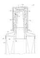
次に、本発明の第一実施例に係る燃料フィルター20の詳細について、図1、乃至、図4を用いて説明する。燃料フィルター20は円筒状のフィルターエレメント23と、該フィルターエレメント23の上下を塞ぐ上部体21と、下部体22とを備え、該上部体21は上方に突出されて、その上部はキャップ24により被装されている。
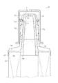
次に、本発明に係る第二実施例における燃料フィルター20について、図5を用いて説明する。第二実施例における燃料フィルター20は、主な構成部品を上述した第一実施例と同じ構成とし、その構成の説明は省略する。そして、前記第一実施例と異なる点は、突部をキャップ24側に設ける代わりに上部体21に設ける構成としている。
次に、本発明に係る第三実施例における燃料フィルター20について、図6、乃至、図8を用いて説明する。第三実施例における燃料フィルター20は、主な構成部品を上述した第一、第二実施例と同じ構成とし、その構成の説明は省略する。そして、前記第一、第二実施例と異なる点は、上部体21のコーン部21a、および、キャップ24の双方に突部を設ける構成としている。
10 燃料配管
20 燃料フィルター
21 上部体
21c エア抜き孔
21d 上部体側突部
23 フィルターエレメント
24 キャップ
24a キャップ側突部
Claims (2)
- 燃料タンク(9)の底部に連通する燃料配管(10)上方の、燃料タンク(9)内部に設けた燃料フィルター(20)であって、前記燃料フィルター(20)は、軸心を上下方向とした円筒状のフィルターエレメント(23)と、前記フィルターエレメント(23)の上部に、上方に突出するように取り付けて、エア抜き穴(21c)を上部中央に備える筒状の上部体(21)と、前記筒状の上部体(21)の上外周を覆う、同じく筒状のキャップ(24)とを備え、前記キャップ(24)の内周上部にキャップ側突部(24a)を形成し、該キャップ側突部(24a)は、該キャップ(24)の軸心と同心で環状に構成して、下方へ突出し、該キャップ側突部(24a)の下端と、該上部体(21)の上端部との間には隙間を形成したことを特徴とする燃料フィルター。
- 請求項1記載の燃料フィルターにおいて、前記キャップ(24)内であって、上部体(21)の外周上部に上部体側突部(21d)を形成したことを特徴とする燃料フィルター。
Priority Applications (1)
| Application Number | Priority Date | Filing Date | Title |
|---|---|---|---|
| JP2008293796A JP5289903B2 (ja) | 2008-11-17 | 2008-11-17 | 燃料フィルター |
Applications Claiming Priority (1)
| Application Number | Priority Date | Filing Date | Title |
|---|---|---|---|
| JP2008293796A JP5289903B2 (ja) | 2008-11-17 | 2008-11-17 | 燃料フィルター |
Publications (2)
| Publication Number | Publication Date |
|---|---|
| JP2010121472A JP2010121472A (ja) | 2010-06-03 |
| JP5289903B2 true JP5289903B2 (ja) | 2013-09-11 |
Family
ID=42323027
Family Applications (1)
| Application Number | Title | Priority Date | Filing Date |
|---|---|---|---|
| JP2008293796A Expired - Fee Related JP5289903B2 (ja) | 2008-11-17 | 2008-11-17 | 燃料フィルター |
Country Status (1)
| Country | Link |
|---|---|
| JP (1) | JP5289903B2 (ja) |
Family Cites Families (5)
| Publication number | Priority date | Publication date | Assignee | Title |
|---|---|---|---|---|
| JPS6439471U (ja) * | 1987-09-01 | 1989-03-09 | ||
| JPH01134061A (ja) * | 1987-11-17 | 1989-05-26 | Honda Motor Co Ltd | 燃料供給系の空気抜き装置 |
| JPH0767949B2 (ja) * | 1993-01-25 | 1995-07-26 | 宝栄工業株式会社 | 燃料タンク用キャップ |
| JPH0828782A (ja) * | 1994-07-22 | 1996-02-02 | Kubota Corp | 給油口用のキャップ |
| JP3380847B2 (ja) * | 1997-11-19 | 2003-02-24 | 株式会社細川洋行 | 流動性内容物取出装置 |
-
2008
- 2008-11-17 JP JP2008293796A patent/JP5289903B2/ja not_active Expired - Fee Related
Also Published As
| Publication number | Publication date |
|---|---|
| JP2010121472A (ja) | 2010-06-03 |
Similar Documents
| Publication | Publication Date | Title |
|---|---|---|
| US8272480B2 (en) | Oil pan integrated with filter and other components | |
| US9222487B2 (en) | Tank breather assembly and mounting configuration | |
| JP2014508877A (ja) | フィルタデバイス | |
| EP0680381B1 (en) | Oil cleaning assemblies for engines | |
| JP6659233B2 (ja) | フィルタエレメント及びフィルタ装置 | |
| JP2005127149A (ja) | オイルパン用バッフルプレートの締結具および締結方法 | |
| JP5289903B2 (ja) | 燃料フィルター | |
| JP2018176146A (ja) | タンク装置 | |
| JP5338568B2 (ja) | オイルミストセパレータ | |
| CN205477818U (zh) | 一种机油滤清器 | |
| US20090095665A1 (en) | Anti-Drainback Valve For An Oil Filter | |
| JP2010174731A (ja) | 燃料フィルタ構造 | |
| JP2004211670A (ja) | ブローバイガス用フィルタ | |
| JPS6135684Y2 (ja) | ||
| JP4534977B2 (ja) | シリンダヘッドカバー | |
| JP2007120444A (ja) | オイルパン | |
| JPS6117204Y2 (ja) | ||
| KR200470069Y1 (ko) | 논 리턴밸브용 밸브 캡의 탈락방지기능을 갖는 오일 필터 | |
| KR100848068B1 (ko) | 자동변속기의 오일필터 | |
| CN221220587U (zh) | 一种油底壳挡油板结构 | |
| JP4400223B2 (ja) | 油液分離器を備えたディーゼル発電装置 | |
| JP6332047B2 (ja) | 水分凝集装置 | |
| CN211082095U (zh) | 一种燃油滤芯 | |
| JP2013136951A (ja) | 燃料フィルタ | |
| CN120332133A (zh) | 油气分离装置 |
Legal Events
| Date | Code | Title | Description |
|---|---|---|---|
| A621 | Written request for application examination |
Free format text: JAPANESE INTERMEDIATE CODE: A621 Effective date: 20110705 |
|
| A977 | Report on retrieval |
Free format text: JAPANESE INTERMEDIATE CODE: A971007 Effective date: 20121018 |
|
| A131 | Notification of reasons for refusal |
Free format text: JAPANESE INTERMEDIATE CODE: A131 Effective date: 20121023 |
|
| A521 | Request for written amendment filed |
Free format text: JAPANESE INTERMEDIATE CODE: A523 Effective date: 20121221 |
|
| TRDD | Decision of grant or rejection written | ||
| A01 | Written decision to grant a patent or to grant a registration (utility model) |
Free format text: JAPANESE INTERMEDIATE CODE: A01 Effective date: 20130528 |
|
| A61 | First payment of annual fees (during grant procedure) |
Free format text: JAPANESE INTERMEDIATE CODE: A61 Effective date: 20130605 |
|
| R150 | Certificate of patent or registration of utility model |
Ref document number: 5289903 Country of ref document: JP Free format text: JAPANESE INTERMEDIATE CODE: R150 |
|
| S531 | Written request for registration of change of domicile |
Free format text: JAPANESE INTERMEDIATE CODE: R313531 |
|
| R350 | Written notification of registration of transfer |
Free format text: JAPANESE INTERMEDIATE CODE: R350 |
|
| R250 | Receipt of annual fees |
Free format text: JAPANESE INTERMEDIATE CODE: R250 |
|
| S533 | Written request for registration of change of name |
Free format text: JAPANESE INTERMEDIATE CODE: R313533 |
|
| R350 | Written notification of registration of transfer |
Free format text: JAPANESE INTERMEDIATE CODE: R350 |
|
| LAPS | Cancellation because of no payment of annual fees |