JP5289903B2 - Fuel filter - Google Patents

Fuel filter Download PDF

Info

Publication number
JP5289903B2
JP5289903B2 JP2008293796A JP2008293796A JP5289903B2 JP 5289903 B2 JP5289903 B2 JP 5289903B2 JP 2008293796 A JP2008293796 A JP 2008293796A JP 2008293796 A JP2008293796 A JP 2008293796A JP 5289903 B2 JP5289903 B2 JP 5289903B2
Authority
JP
Japan
Prior art keywords
fuel
cap
upper body
side protrusion
filter
Prior art date
Legal status (The legal status is an assumption and is not a legal conclusion. Google has not performed a legal analysis and makes no representation as to the accuracy of the status listed.)
Expired - Fee Related
Application number
JP2008293796A
Other languages
Japanese (ja)
Other versions
JP2010121472A (en
Inventor
昌史 相良
Current Assignee (The listed assignees may be inaccurate. Google has not performed a legal analysis and makes no representation or warranty as to the accuracy of the list.)
Yanmar Co Ltd
Original Assignee
Yanmar Co Ltd
Priority date (The priority date is an assumption and is not a legal conclusion. Google has not performed a legal analysis and makes no representation as to the accuracy of the date listed.)
Filing date
Publication date
Application filed by Yanmar Co Ltd filed Critical Yanmar Co Ltd
Priority to JP2008293796A priority Critical patent/JP5289903B2/en
Publication of JP2010121472A publication Critical patent/JP2010121472A/en
Application granted granted Critical
Publication of JP5289903B2 publication Critical patent/JP5289903B2/en
Expired - Fee Related legal-status Critical Current
Anticipated expiration legal-status Critical

Links

Images

Description

本発明は、燃料タンク内部に設けた燃料フィルターにおいて、濾過されていない燃料の一部が燃料フィルター内部に侵入するのを防止するための技術に関する。   The present invention relates to a technique for preventing a part of unfiltered fuel from entering a fuel filter in a fuel filter provided inside the fuel tank.

従来から、エンジンにおいては、燃料噴射ポンプに供給する燃料中の塵埃やゴミ等の混入物を除去するために、燃料フィルターを経由させて、燃料タンクから燃料噴射ポンプに燃料を供給する技術が知られている。そして、小型エンジンの場合には、全体レイアウトのコンパクト化の要望等から、燃料フィルターは燃料タンク内部に設けられる場合がある(例えば、特許文献1参照。)。このような燃料フィルターを設ける場合、エンジン回転数を安定させるために、フィルターエレメントによって濾過された燃料中に含まれるエアを、燃料タンク内部に効率良く開放する必要がある。そのため、燃料フィルターは、フィルターエレメントの上端部において上方に突出する上部体を嵌設し、該上部体の上端部にキャップを被装させ、該キャップ内部に空気溜りを形成するとともに、該上部体の上端部にエア抜き孔を設ける構成としている。そして、濾過された燃料はフィルターエレメント内部や、上部体内部に充填されることとなり、前記燃料中に含まれるエアは、気泡となって上部体の内部を浮上し、エア抜き孔を介して一旦空気溜りに集められ、その後、燃料タンク内に開放されることとなる。
特開2004−270641号公報
2. Description of the Related Art Conventionally, in an engine, a technique for supplying fuel from a fuel tank to a fuel injection pump via a fuel filter in order to remove contaminants such as dust and dirt in the fuel supplied to the fuel injection pump is known. It has been. In the case of a small engine, the fuel filter may be provided inside the fuel tank in order to reduce the overall layout (for example, see Patent Document 1). When such a fuel filter is provided, it is necessary to efficiently release the air contained in the fuel filtered by the filter element into the fuel tank in order to stabilize the engine speed. Therefore, the fuel filter has an upper body protruding upward at the upper end portion of the filter element, a cap is mounted on the upper end portion of the upper body, and an air pocket is formed inside the cap. It is set as the structure which provides an air vent hole in the upper end part. The filtered fuel is filled inside the filter element and inside the upper body, and the air contained in the fuel becomes bubbles and floats inside the upper body and temporarily passes through the air vent hole. It is collected in an air reservoir and then released into the fuel tank.
JP 2004-270641 A

このようなキャップ内部に形成する空気溜りを用いる場合、エンジン稼働時の振動や、不意にエンジン本体が傾倒した場合等により、燃料タンク内部の燃料の油面が波打ち、燃料の一部がキャップの内側面、あるいは、上部体の外側面を伝って空気溜りに入り込み、エア抜き孔を介して燃料フィルター内に侵入する場合がある。その結果、未だ濾過されていない塵埃やゴミ等を含む燃料が、燃料噴射ポンプや、燃料噴射ノズル等からなる燃料噴射系に送られ、これら装置類に摩耗が発生し、エンジン全体の故障の原因にもなっていた。以上の点を鑑み、本発明においては、燃料タンク内部に設けた燃料フィルターにおいて、濾過されていない燃料の一部が、燃料フィルター内部に侵入するのを、簡易、かつ、効果的に防止するための技術の提供を課題とする。   When an air pocket formed inside such a cap is used, the oil level of the fuel inside the fuel tank undulates due to vibration during engine operation or the engine body tilting unexpectedly, and part of the fuel is There is a case where the air enters the air reservoir through the inner side surface or the outer side surface of the upper body and enters the fuel filter through the air vent hole. As a result, fuel containing dust and debris that has not yet been filtered is sent to a fuel injection system consisting of a fuel injection pump, a fuel injection nozzle, etc., and these devices wear out, causing a failure of the entire engine. It was also. In view of the above points, in the present invention, in the fuel filter provided in the fuel tank, in order to easily and effectively prevent a part of the unfiltered fuel from entering the fuel filter. The issue is to provide the technology.

本発明の解決しようとする課題は以上の如くであり、次にこの課題を解決するための手段を説明する。   The problem to be solved by the present invention is as described above. Next, means for solving the problem will be described.

請求項1においては、燃料タンク(9)の底部に連通する燃料配管(10)上方の、燃料タンク(9)内部に設けた燃料フィルター(20)であって、前記燃料フィルター(20)は、軸心を上下方向とした円筒状のフィルターエレメント(23)と、前記フィルターエレメント(23)の上部に、上方に突出するように取り付けて、エア抜き穴(21c)を上部中央に備える筒状の上部体(21)と、前記筒状の上部体(21)の上外周を覆う、同じく筒状のキャップ(24)とを備え、前記キャップ(24)の内周上部にキャップ側突部(24a)を形成し、該キャップ側突部(24a)は、該キャップ(24)の軸心と同心で環状に構成して、下方へ突出し、該キャップ側突部(24a)の下端と、該上部体(21)の上端部との間には隙間を形成したものである。 In claim 1, a fuel filter (20) provided in the fuel tank (9) above the fuel pipe (10) communicating with the bottom of the fuel tank (9), wherein the fuel filter (20) a cylindrical filter element which has an axis and the vertical direction (23), the upper portion of the filter element (23), mounted so as to protrude upward, cylindrical with a air vent hole (21c) at the upper center upper body (21), the tubular covering the outer periphery on the upper body (21), likewise provided with a cylindrical cap (24), the inner periphery upper cap side protrusion of said cap (24) (24a The cap-side protrusion (24a) is formed concentrically with the axis of the cap (24) and protrudes downward, and the lower end of the cap-side protrusion (24a) and the upper portion Between the upper end of the body (21) It is obtained by forming a gap.

請求項2においては、請求項1記載の燃料フィルターにおいて、前記キャップ(24)内であって、上部体(21)の外周上部に上部体側突部(21d)を形成したものである。 According to a second aspect of the present invention, in the fuel filter according to the first aspect, an upper body-side protrusion (21d) is formed in the cap (24) on the outer periphery of the upper body (21) .

本発明の効果として、以下に示すような効果を奏する。   As effects of the present invention, the following effects can be obtained.

請求項1においては、燃料タンク内部に設けた燃料フィルターにおいて、濾過されていない燃料の一部が燃料フィルター内部に侵入するのを簡易、かつ、効果的に防止することができる。   According to the first aspect of the present invention, in the fuel filter provided in the fuel tank, it is possible to easily and effectively prevent a part of the unfiltered fuel from entering the fuel filter.

請求項2においては、キャップの内面や、上部体の側面を伝い、燃料フィルター内に侵入する燃料を、より効果的に防ぐことができる。   According to the second aspect of the present invention, it is possible to more effectively prevent the fuel entering the fuel filter through the inner surface of the cap and the side surface of the upper body.

次に、発明の実施の形態を説明する。   Next, embodiments of the invention will be described.

図1はエンジンの全体的な構成を示した正面断面図、図2は第一実施例に係る燃料タンクの構成を示した側面面断面図である。   FIG. 1 is a front sectional view showing the overall configuration of the engine, and FIG. 2 is a side sectional view showing the configuration of the fuel tank according to the first embodiment.

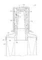
図3は第一実施例に係る燃料フィルターの構成を示した正面断面図である。   FIG. 3 is a front sectional view showing the configuration of the fuel filter according to the first embodiment.

図4は同じくキャップ側突部の形状の異なる燃料フィルターの構成を示した正面断面図である。   FIG. 4 is a front cross-sectional view showing the structure of a fuel filter having a different cap-side protrusion shape.

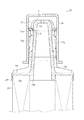
図5は第二実施例に係る燃料フィルターの構成を示した正面断面図、図6は第三実施例に係る燃料フィルターの構成を示した正面断面図である。   FIG. 5 is a front sectional view showing the configuration of the fuel filter according to the second embodiment, and FIG. 6 is a front sectional view showing the configuration of the fuel filter according to the third embodiment.

図7は同じくキャップ側突部の形状の異なる燃料フィルターの構成を示した正面断面図である。   FIG. 7 is a front sectional view showing the structure of a fuel filter having a different cap-side protrusion.

図8は同じくキャップ側突部と上部体側突部とを水平方向に対向して設けた燃料フィルターの構成を示した正面断面図である。   FIG. 8 is a front sectional view showing the configuration of a fuel filter in which a cap-side protrusion and an upper body-side protrusion are provided so as to face each other in the horizontal direction.

[エンジン1]
まず、本実施例に係るエンジン1について、図1、および、図2を用いて説明する。エンジン1の本体は、その上部を形成するシリンダブロック2や、その下部を形成するクランクケース5等によって構成される。シリンダブロック2の内部中央には上下方向にシリンダ2aが形成され、ピストン4が収納されている。また、クランクケース5上部の左右中央にはクランク軸3やカム軸13が平行に軸支され、ピストン4とクランク軸3とはコンロッド17を介して連結されている。
[Engine 1]
First, the engine 1 according to the present embodiment will be described with reference to FIGS. 1 and 2. The main body of the engine 1 includes a cylinder block 2 that forms an upper portion thereof, a crankcase 5 that forms a lower portion thereof, and the like. A cylinder 2a is formed in the center of the cylinder block 2 in the vertical direction, and the piston 4 is accommodated therein. In addition, a crankshaft 3 and a camshaft 13 are supported in parallel at the left and right centers of the upper part of the crankcase 5, and the piston 4 and the crankshaft 3 are connected via a connecting rod 17.

シリンダブロック2の上部にはシリンダヘッド6が設けられ、該シリンダヘッド6の上部はボンネット7によって覆われるとともに、該ボンネット7の内部には弁腕室が構成される。   A cylinder head 6 is provided on the upper portion of the cylinder block 2, and the upper portion of the cylinder head 6 is covered with a bonnet 7, and a valve arm chamber is formed inside the bonnet 7.

シリンダヘッド6の左右中央には上下方向に燃料噴射ノズル11が貫設されており、該燃料噴射ノズル11を介してシリンダ2a内に燃料が供給される。また、ボンネット7の一側(図1における左側)にはマフラー8が配置され、他側(図1における右側)には燃料タンク9が配置されている。   A fuel injection nozzle 11 is provided vertically through the center of the cylinder head 6 in the vertical direction, and fuel is supplied into the cylinder 2 a via the fuel injection nozzle 11. A muffler 8 is disposed on one side (left side in FIG. 1) of the bonnet 7, and a fuel tank 9 is disposed on the other side (right side in FIG. 1).

一方、シリンダブロック2の下部において、クランクケース5内の一側(図1における右側)にはガバナ27が配置され、その上部には燃料噴射ポンプ12が配置されている。   On the other hand, in the lower part of the cylinder block 2, a governor 27 is arranged on one side (right side in FIG. 1) in the crankcase 5, and a fuel injection pump 12 is arranged on the upper part thereof.

ここで図2に示すように、燃料タンク9内部の底面には燃料フィルター20が内設され、該燃料フィルター20の下方には燃料タンク9の下面を間に挟んで配管ブロック26が固設される。前記配管ブロック26は長方形状の部材からなり、長手方向を前後方向として配設され、一方の側面部からはL状に屈曲した管状部材からなる燃料出口26aが突出されるとともに、その内部には上面から該燃料出口26aへ連通される連通孔26bが形成されている。   Here, as shown in FIG. 2, a fuel filter 20 is provided inside the bottom surface of the fuel tank 9, and a piping block 26 is fixed below the fuel filter 20 with the lower surface of the fuel tank 9 interposed therebetween. The The piping block 26 is made of a rectangular member, and is disposed with the longitudinal direction as the front-rear direction. A fuel outlet 26a made of a tubular member bent in an L shape protrudes from one side surface portion, and the inside thereof has an inside. A communication hole 26b communicating with the fuel outlet 26a from the upper surface is formed.

そして、配管ブロック26の連通孔26bは、燃料タンク9の下面に設けられた貫通孔9aを介して、燃料フィルター20の内部と連通され、燃料出口26aと、燃料噴射ポンプ12の吸入部12cとは燃料配管10によって連通されるとともに、燃料噴射ポンプ12の吐出部12dと、燃料噴射ノズル11の吸入部11aと、は高圧管19によって連通されている。   The communication hole 26 b of the piping block 26 is communicated with the inside of the fuel filter 20 through a through hole 9 a provided in the lower surface of the fuel tank 9, and the fuel outlet 26 a and the suction portion 12 c of the fuel injection pump 12. Are connected by a fuel pipe 10, and a discharge part 12 d of the fuel injection pump 12 and a suction part 11 a of the fuel injection nozzle 11 are connected by a high-pressure pipe 19.

一方、クランク軸3の一側には歯車15が外嵌固定されており、カム軸13に外嵌されたカムギヤ18と、前記歯車15とは互いに噛合している。また、カム軸13の中途部に形成されたポンプ駆動カム14は燃料噴射ポンプ12のプランジャ12aの一端に設けられた転動体であるローラ12bと当接している。   On the other hand, a gear 15 is fitted and fixed to one side of the crankshaft 3, and the cam gear 18 fitted on the camshaft 13 and the gear 15 mesh with each other. A pump drive cam 14 formed in the middle of the camshaft 13 is in contact with a roller 12b that is a rolling element provided at one end of the plunger 12a of the fuel injection pump 12.

このように、エンジン1ではクランク軸3が回転すると、歯車15、および、カムギヤ18を介してカム軸13も回転され、ポンプ駆動カム14の回転動作に追従して燃料噴射ポンプ12のプランジャ12aが摺動するようになっている。   Thus, in the engine 1, when the crankshaft 3 rotates, the camshaft 13 also rotates through the gear 15 and the cam gear 18, and the plunger 12 a of the fuel injection pump 12 follows the rotational operation of the pump drive cam 14. It comes to slide.

そして、プランジャ12aの摺動により吸引力が発生し、燃料タンク9に貯溜された燃料は、一旦燃料フィルター20によって濾過された後、配管ブロック26から燃料配管10を介して燃料噴射ポンプ12に送られ、その後、高圧管19を介して所定のタイミングで所定量の燃料が燃料噴射ノズル11に供給されるようになっている。   Then, a suction force is generated by the sliding of the plunger 12a, and the fuel stored in the fuel tank 9 is once filtered by the fuel filter 20, and then sent from the piping block 26 to the fuel injection pump 12 through the fuel piping 10. Thereafter, a predetermined amount of fuel is supplied to the fuel injection nozzle 11 through the high-pressure pipe 19 at a predetermined timing.

[燃料フィルター20(第一実施例)]
次に、本発明の第一実施例に係る燃料フィルター20の詳細について、図1、乃至、図4を用いて説明する。燃料フィルター20は円筒状のフィルターエレメント23と、該フィルターエレメント23の上下を塞ぐ上部体21と、下部体22とを備え、該上部体21は上方に突出されて、その上部はキャップ24により被装されている。
[Fuel filter 20 (first embodiment)]
Next, details of the fuel filter 20 according to the first embodiment of the present invention will be described with reference to FIGS. 1 to 4. The fuel filter 20 includes a cylindrical filter element 23, an upper body 21 that closes the upper and lower sides of the filter element 23, and a lower body 22. The upper body 21 protrudes upward, and the upper part is covered by a cap 24. It is disguised.

まず、上部体21について説明する。上部体21は樹脂製部材からなり、上端部を塞がれた筒状のコーン部21aと、該コーン部21a下部の外周より外方に延設された円板状の鍔部21bとにより一体的に形成される。   First, the upper body 21 will be described. The upper body 21 is made of a resin member, and is integrally formed by a cylindrical cone portion 21a whose upper end portion is closed and a disk-shaped flange portion 21b extending outward from the outer periphery of the lower portion of the cone portion 21a. Formed.

コーン部21aはフィルターエレメント23よりも上部に配置されており、該コーン部21aの上端部中央にはエア抜き孔21cが穿孔され、該エア抜き孔21cを介してコーン部21aの内部と外部とが連通されるようになっている。また、コーン部21aの上下中央から下方にかけては、その外径寸法が緩やかに広がるテーパ状に形成されるとともに、その側面には外方に向かって複数のリブ21g・21g・・・が形成されている。前記リブ21gは平面視にて放射状に設けられ、かつ、側面視にてコーン部21aの形状に沿って、上端部から下方に向かって帯状に形成される。   The cone portion 21a is disposed above the filter element 23, and an air vent hole 21c is drilled at the center of the upper end portion of the cone portion 21a, and the inside and outside of the cone portion 21a are connected via the air vent hole 21c. Are communicated. In addition, the cone portion 21a is formed in a tapered shape whose outer diameter is gradually widened from the upper and lower center to the lower side, and a plurality of ribs 21g, 21g,. ing. The ribs 21g are provided radially in a plan view, and are formed in a strip shape from the upper end portion downward along the shape of the cone portion 21a in a side view.

一方、コーン部21aの下端部21eは鍔部21bより僅かに下方に突出して設けられている。また、鍔部21bの外縁部21fは下方に僅かに屈曲されており、前記下端部21eと外縁部21fとの間にフィルターエレメント23の上部を嵌合する構成としている。   On the other hand, the lower end portion 21e of the cone portion 21a is provided so as to protrude slightly downward from the flange portion 21b. The outer edge portion 21f of the flange portion 21b is slightly bent downward, and the upper portion of the filter element 23 is fitted between the lower end portion 21e and the outer edge portion 21f.

次に、キャップ24について説明する。キャップ24は樹脂製部材により構成され、前記鍔部21bより上側のコーン部21aを覆う構成とされ、該キャップ24の内径寸法はコーン部21aの下側外径と略同じ大きさとして、キャップ24の内側上面とコーン部21a上面との間に若干の空間を有し、キャップ24の内側面とコーン部21aの外側面との間にも空間を有することで、空気溜り25を形成している。また、キャップ24下端内面では、互いに隣接するリブ21gとリブ21gの間の空間が、キャップ24の内部と外部を連通する構成としている。   Next, the cap 24 will be described. The cap 24 is made of a resin member, and is configured to cover the cone portion 21a above the flange portion 21b. The inner diameter of the cap 24 is substantially the same as the lower outer diameter of the cone portion 21a. The air reservoir 25 is formed by having a slight space between the inner upper surface of the cap and the upper surface of the cone portion 21a and also having a space between the inner surface of the cap 24 and the outer surface of the cone portion 21a. . Further, on the inner surface of the lower end of the cap 24, the space between the ribs 21g adjacent to each other and the ribs 21g communicates the inside and the outside of the cap 24.

また、図3に示すように、キャップ24の内周上部には、該キャップ24の軸心と同心で環状に下方に、または、内方に突出されたキャップ側突部24aが設けられている。該キャップ側突部24aは、本実施例ではキャップ24上内面にコーン部21aの上端部に比べて大きな外径寸法で、その断面形状は矩形状に形成され、キャップ側突部24aとコーン部21a上端部との間には隙間が形成されている。即ち、前記キャップ側突部24aの突出高さ(図3における寸法X)は空気溜り25の隙間間隔(図3における寸法Y)に比べて、小さくなるように形成されている。   Further, as shown in FIG. 3, a cap-side protrusion 24a that is concentric with the axial center of the cap 24 and annularly downward or inwardly protrudes is provided on the inner peripheral upper portion of the cap 24. . In this embodiment, the cap-side protrusion 24a has a larger outer diameter than the upper end of the cone portion 21a on the inner surface of the cap 24, and has a rectangular cross-sectional shape. The cap-side protrusion 24a and the cone portion A gap is formed between the upper end of 21a. That is, the protrusion height of the cap-side protrusion 24a (dimension X in FIG. 3) is formed to be smaller than the gap interval (dimension Y in FIG. 3) of the air reservoir 25.

なお、キャップ側突部24aの断面形状は矩形状に限定されるものではなく、例えば、図4に示すように直角三角形状とし、側面視にて下方に向かって外形が窄まるテーパ形状に形成してもよい。   Note that the cross-sectional shape of the cap-side protrusion 24a is not limited to a rectangular shape. For example, the cap-side protruding portion 24a has a right triangle shape as shown in FIG. May be.

次に、下部体22について説明する。下部体22は円板状の部材からなり、その中央部には上下方向に貫通する連通孔22aが設けられる。また、下部体22の上面において、外周と連通孔22aの周囲からは上方に突設して断面視凹状として縁部22bが設けられ、該縁部22bにフィルターエレメント23の下部を嵌合する構成としている。   Next, the lower body 22 will be described. The lower body 22 is made of a disk-shaped member, and a communication hole 22a penetrating in the vertical direction is provided at the center thereof. Further, on the upper surface of the lower body 22, an edge portion 22b is provided so as to protrude upward from the outer periphery and the periphery of the communication hole 22a so as to have a concave shape in cross section, and the lower portion of the filter element 23 is fitted to the edge portion 22b. It is said.

そして、下部体22の底面において、複数箇所に貫通孔が設けられ、ボルト等により下部体22と燃料タンク9と配管ブロック26を固定する構成としている。なお、ボルトの数については本実施例に限定するものではない。   And the through-hole is provided in several places in the bottom face of the lower body 22, and it is set as the structure which fixes the lower body 22, the fuel tank 9, and the piping block 26 with a volt | bolt etc. The number of bolts is not limited to the present embodiment.

次に、フィルターエレメント23について説明する。フィルターエレメント23は、例えば、多孔質材等により構成される濾材を円筒状に形成し、この円筒状の軸心を上下方向として、その上端部に上部体21を嵌合し、その下端部に下部体22を嵌合する構成としている。   Next, the filter element 23 will be described. The filter element 23 is formed, for example, in a cylindrical shape by using a porous material or the like, and the upper body 21 is fitted to the upper end portion of the cylindrical shaft center in the vertical direction, and the lower end portion thereof. The lower body 22 is configured to be fitted.

このような構成からなる燃料フィルター20は、燃料タンク9内部の底面に固定され、前記燃料タンク9の下面に設けられた配管ブロック26を介して、燃料配管10と連通される。   The fuel filter 20 having such a configuration is fixed to the bottom surface inside the fuel tank 9 and communicates with the fuel pipe 10 through a pipe block 26 provided on the bottom surface of the fuel tank 9.

そして、燃料タンク9が空の状態から燃料を入れると、該燃料は燃料フィルター20のフィルターエレメント23を通過して濾過されてダスト等が取り除かれた後に、下部体22の中央に設けられた連通孔22aを介して配管ブロック26へと流下し、その後、燃料配管10を介して燃料噴射ポンプ12(図1を参照)へと送られる。この際、配管ブロック26や、燃料配管10等内の空気は燃料内を上昇し、燃料フィルター20内の上部からエア抜き孔21c、空気溜り25を介して上方へ抜ける。   Then, when the fuel is introduced from the state in which the fuel tank 9 is empty, the fuel is filtered through the filter element 23 of the fuel filter 20 to remove dust and the like, and then the communication provided in the center of the lower body 22 is provided. It flows down to the piping block 26 through the hole 22a, and then sent to the fuel injection pump 12 (see FIG. 1) through the fuel piping 10. At this time, the air in the pipe block 26 and the fuel pipe 10 etc. rises in the fuel and escapes upward from the upper part of the fuel filter 20 through the air vent hole 21 c and the air reservoir 25.

燃料タンク9内に燃料が満たされた状態では、上部体21のコーン部21aの内部、および、キャップ24内の空気溜り25に所定量の空気が溜まっており、燃料中に含まれる空気が燃料フィルター20や燃料配管10を通過する際に集合して気泡となり、該気泡となった空気は上昇して上部体21のコーン部21a内に溜まる。そして、所定量以上の空気はキャップ24下側部より溢れ出て上昇し、燃料タンク9内に排出される。   In a state where the fuel tank 9 is filled with fuel, a predetermined amount of air is accumulated in the cone portion 21a of the upper body 21 and the air reservoir 25 in the cap 24, and the air contained in the fuel is fuel. When passing through the filter 20 and the fuel pipe 10, they gather to form bubbles, and the air that has become bubbles rises and accumulates in the cone portion 21 a of the upper body 21. Then, a predetermined amount or more of air overflows from the lower side of the cap 24 and rises and is discharged into the fuel tank 9.

このように、キャップ24内の空気溜り25、および、上部体21のコーン部21aの内部に空気が溜まっているため、キャップ24外側の燃料タンク9内部の未だ濾過されていない燃料が燃料フィルター20内に入り込むことはない。   Thus, since air is accumulated in the air reservoir 25 in the cap 24 and the cone portion 21 a of the upper body 21, the fuel that has not yet been filtered inside the fuel tank 9 outside the cap 24 is removed from the fuel filter 20. It does not get inside.

しかし、エンジン1の稼働時の振動や、不意にエンジン1本体が傾倒した場合等により、燃料タンク9内部の燃料の油面が波打ち、燃料の一部がキャップ24の内側面を伝って空気溜り25内に浸入する場合がある。   However, the oil level of the fuel inside the fuel tank 9 undulates due to vibration during operation of the engine 1 or when the main body of the engine 1 tilts unexpectedly, and a part of the fuel travels along the inner surface of the cap 24 and collects air. 25 may enter.

このような場合、従来では濾過していない燃料の一部がキャップ24内の空気溜り25を上昇して、エア抜き孔21cから燃料フィルター20内部に入ることがあり、故障の原因となることがあった。しかしながら、本発明ではキャップ24内にキャップ側突部24aを設けることで、燃料の一部がエア抜き孔21cを介して燃料フィルター20内部に流入することを防ぐようになっている。   In such a case, part of the fuel that has not been filtered in the past may rise in the air reservoir 25 in the cap 24 and enter the fuel filter 20 from the air vent hole 21c, which may cause a failure. there were. However, in the present invention, by providing the cap-side protrusion 24a in the cap 24, a part of the fuel is prevented from flowing into the fuel filter 20 through the air vent hole 21c.

即ち、燃料の一部がキャップ24内の上部にまで達したとしても、ミスト状の燃料はキャップ側突部24aに当接することにより集められ、液体となってキャップ側突部24a外周からそのまま下方へ落下する。また、液体の燃料はキャップ側突部24aで堰止められてそのまま落下する。こうして、燃料タンク9内部へと戻されることになる。   That is, even if a part of the fuel reaches the upper part in the cap 24, the mist-like fuel is collected by contacting the cap-side protrusion 24a and becomes a liquid, and is directly lowered from the outer periphery of the cap-side protrusion 24a. Fall to. Further, the liquid fuel is blocked by the cap-side protrusion 24a and falls as it is. Thus, the fuel tank 9 is returned to the inside.

そして、キャップ側突部24aの外径はコーン部21aの上端部の外径に比べて大きな寸法となるように形成されているため、前記燃料がキャップ側突部24aの外側面からエア抜き孔21cに流入されることは殆どない。   Since the outer diameter of the cap-side protrusion 24a is formed to be larger than the outer diameter of the upper end portion of the cone portion 21a, the fuel is vented from the outer surface of the cap-side protrusion 24a. Almost no flow into 21c.

さらに、図4に示すように、キャップ側突部24aの形状を、側面視にて下方に向かって外径が窄まるテーパ状に形成することにより、キャップ側突部24aの下端に至った燃料は留まることなく、その自重によって速やかに落下するようになるのである。   Further, as shown in FIG. 4, the fuel that has reached the lower end of the cap-side protrusion 24 a is formed by forming the shape of the cap-side protrusion 24 a into a tapered shape whose outer diameter is narrowed downward in a side view. Without stopping, it will fall quickly due to its own weight.

このように、本発明における第一実施例に係る燃料フィルター20は、燃料タンク9の底部に連通する燃料配管10上方の、燃料タンク9内部に設けた燃料フィルター20であって、前記燃料フィルター20は、軸心を上下方向とした円筒状のフィルターエレメント23と、前記フィルターエレメント23の上部に、上方に突出するように取り付けて、エア抜き孔21cを上部中央に備える上部体21と、前記上部体21の上外周を覆うキャップ24とを備え、前記キャップ24の内周上部にキャップ側突部24aを形成することとしている。   As described above, the fuel filter 20 according to the first embodiment of the present invention is the fuel filter 20 provided in the fuel tank 9 above the fuel pipe 10 communicating with the bottom of the fuel tank 9, and the fuel filter 20 Includes a cylindrical filter element 23 having an axial center in the vertical direction, an upper body 21 attached to the upper portion of the filter element 23 so as to protrude upward, and an air vent hole 21c at the upper center, and the upper portion A cap 24 that covers the upper and outer periphery of the body 21, and a cap-side protrusion 24 a is formed on the inner periphery of the cap 24.

このような構成とすることで、燃料タンク9内部に設けた燃料フィルター20において、濾過されていない燃料の一部が燃料フィルター20内部に侵入するのを簡易、かつ、効果的に防止することができる。   With such a configuration, in the fuel filter 20 provided in the fuel tank 9, it is possible to easily and effectively prevent a part of unfiltered fuel from entering the fuel filter 20. it can.

つまり、フィルターエレメント23で濾過されていない、ダスト等を含む燃料が燃料フィルター20内部に流入することを単純な形状により防ぐことができるため、燃料噴射ポンプ12へは常にダスト等を含まないクリーンな燃料を供給することができ、燃料噴射ポンプ12や、燃料噴射ノズル11等から構成される燃料噴射装置全体の摩耗を減少させ、メンテナンス期間が延びることから、エンジン1全体の経済性を向上させることができる。また、燃料噴射ノズル11を介して、常にクリーンな燃料をシリンダブロック2内に供給することができるため、エンジン1の出力効率を向上させることができるのである。   That is, since it is possible to prevent the fuel containing dust and the like that has not been filtered by the filter element 23 from flowing into the fuel filter 20 with a simple shape, the fuel injection pump 12 is always clean and free of dust and the like. Fuel can be supplied, the wear of the entire fuel injection device composed of the fuel injection pump 12, the fuel injection nozzle 11 and the like is reduced, and the maintenance period is extended, so that the economy of the entire engine 1 is improved. Can do. In addition, since clean fuel can always be supplied into the cylinder block 2 via the fuel injection nozzle 11, the output efficiency of the engine 1 can be improved.

[燃料フィルター20(第二実施例)]
次に、本発明に係る第二実施例における燃料フィルター20について、図5を用いて説明する。第二実施例における燃料フィルター20は、主な構成部品を上述した第一実施例と同じ構成とし、その構成の説明は省略する。そして、前記第一実施例と異なる点は、突部をキャップ24側に設ける代わりに上部体21に設ける構成としている。
[Fuel filter 20 (second embodiment)]
Next, the fuel filter 20 in the second embodiment according to the present invention will be described with reference to FIG. The fuel filter 20 in the second embodiment has the same main components as those in the first embodiment described above, and the description of the configuration is omitted. The difference from the first embodiment is that the protrusion is provided on the upper body 21 instead of on the cap 24 side.

即ち、コーン部21aの外周上部に環状の上部体側突部21dを形成し、該上部体側突部21dによって燃料の一部が空気溜り25からフィルター20内部に侵入しようとすることを防ぐ構成としている。   That is, an annular upper body side protrusion 21d is formed on the outer periphery of the cone portion 21a, and the upper body side protrusion 21d prevents a part of fuel from entering the inside of the filter 20 from the air reservoir 25. .

つまり、燃料タンク9内部の燃料の油面が波打つ等で、燃料の一部がコーン部21aの外側面を伝って上部にまで達したとしても、ミスト状の燃料は上部体側突部21dに当接することにより集められ、液体となってそのままコーン部21aの外周に沿って下方へ落下する。また、液体の燃料は上部体側突部21dで堰止められてそのまま落下することになる。従って、燃料の一部がエア抜き孔21cを介して燃料フィルター20内に流入することを効果的に防ぐことができる。   In other words, even if a part of the fuel reaches the upper part through the outer side surface of the cone part 21a because the oil level of the fuel inside the fuel tank 9 undulates, the mist-like fuel hits the upper body side projecting part 21d. It collects by contact, turns into a liquid, and falls down along the outer periphery of the cone part 21a as it is. Further, the liquid fuel is blocked by the upper body side projection 21d and falls as it is. Accordingly, it is possible to effectively prevent a part of the fuel from flowing into the fuel filter 20 through the air vent hole 21c.

ここで、本実施例においては、上部体側突部21dの断面形状を直角三角形状とし、該上部体側突部21d全体として、側面視にて下方に向かって外径が窄まるテーパ状に形成することとしている。これにより、前記燃料の一部が上部体側突部21dに留まることなく速やかに下方に落下させることができるのである。なお、上部体側突部21dの断面形状は直角三角形状や矩形状に限定されるものではない。   In this embodiment, the cross-sectional shape of the upper body side projection 21d is a right triangle, and the entire upper body side projection 21d is formed in a tapered shape whose outer diameter narrows downward in a side view. I am going to do that. Thereby, a part of the fuel can be quickly dropped downward without staying at the upper body side protrusion 21d. It should be noted that the cross-sectional shape of the upper body side projection 21d is not limited to a right triangle or a rectangle.

このように、本発明における第二実施例に係る燃料フィルター20は、燃料タンク9の底部に連通する燃料配管10上方の、燃料タンク9内部に設けた燃料フィルター20であって、前記燃料フィルター20は、軸心を上下方向とした円筒状のフィルターエレメント23と、前記フィルターエレメント23の上部に、上方に突出するように取り付けて、エア抜き孔21cを上部中央に備える上部体21と、前記上部体21の上外周を覆うキャップ24とを備え、前記上部体21の外周上部に上部体側突部21dを形成することとしている。   As described above, the fuel filter 20 according to the second embodiment of the present invention is the fuel filter 20 provided in the fuel tank 9 above the fuel pipe 10 communicating with the bottom of the fuel tank 9, and the fuel filter 20 Includes a cylindrical filter element 23 having an axial center in the vertical direction, an upper body 21 attached to the upper portion of the filter element 23 so as to protrude upward, and an air vent hole 21c at the upper center, and the upper portion And a cap 24 that covers the upper and outer peripheries of the body 21, and upper body-side protrusions 21 d are formed on the outer periphery of the upper body 21.

このような構成とすることで、燃料タンク9内部に設けた燃料フィルター20において、濾過されていない燃料の一部が燃料フィルター20内部に侵入するのを簡易、かつ、効果的に防止することができる。   With such a configuration, in the fuel filter 20 provided in the fuel tank 9, it is possible to easily and effectively prevent a part of unfiltered fuel from entering the fuel filter 20. it can.

つまり、上述の第一実施例と同様に、フィルターエレメント23に濾過されていないような、ダスト等を含む燃料が燃料フィルター20内に流入することを単純な形状により効果的に防ぐことができるため、燃料噴射ポンプ12へは常にダスト等を含まないクリーンな燃料を供給することができ、燃料噴射ポンプ12や、燃料噴射ノズル11等から構成される燃料噴射装置全体の摩耗を減少し、メンテナンス期間が延びることから、エンジン1全体の経済性を向上させることができるのである。また、燃料噴射ノズル11を介して常にクリーンな燃料をシリンダブロック2内に供給することができるため、エンジン1の出力効率を向上させることができるのである。   That is, as in the first embodiment described above, it is possible to effectively prevent the fuel containing dust or the like that has not been filtered by the filter element 23 from flowing into the fuel filter 20 with a simple shape. The fuel injection pump 12 can always be supplied with clean fuel that does not contain dust and the like, reducing the wear of the entire fuel injection device including the fuel injection pump 12 and the fuel injection nozzle 11, and the maintenance period. Therefore, the economic efficiency of the entire engine 1 can be improved. Further, since clean fuel can always be supplied into the cylinder block 2 through the fuel injection nozzle 11, the output efficiency of the engine 1 can be improved.

[燃料フィルター(第三実施例)]
次に、本発明に係る第三実施例における燃料フィルター20について、図6、乃至、図8を用いて説明する。第三実施例における燃料フィルター20は、主な構成部品を上述した第一、第二実施例と同じ構成とし、その構成の説明は省略する。そして、前記第一、第二実施例と異なる点は、上部体21のコーン部21a、および、キャップ24の双方に突部を設ける構成としている。
[Fuel filter (third embodiment)]
Next, the fuel filter 20 in the third embodiment according to the present invention will be described with reference to FIGS. The fuel filter 20 in the third embodiment has the same components as those in the first and second embodiments described above, and the description of the configuration is omitted. The difference from the first and second embodiments is that the projections are provided on both the cone portion 21 a of the upper body 21 and the cap 24.

即ち、図6に示すように、キャップ24の内周上部にキャップ側突部24aが設けられ、上部体21のコーン部21aの外周上部には環状の上部体側突部21dが設けられる。   That is, as shown in FIG. 6, a cap-side protrusion 24 a is provided on the inner periphery of the cap 24, and an annular upper body-side protrusion 21 d is provided on the outer periphery of the cone 21 a of the upper body 21.

そして、キャップ側突部24aの形状は第一実施例と同様に、矩形状断面からなる筒状(図6を参照)、あるいは、側面視にて下方に向かって外径が窄まるテーパ状(図7を参照)等によって形成される一方、上部体側突部21dの形状は、第二実施例と同様に、側面視にて下方に向かって外径が窄まるテーパ状に形成することとしている。   And the shape of the cap side protrusion 24a is a cylindrical shape (see FIG. 6) having a rectangular cross section, or a tapered shape whose outer diameter is narrowed downward in a side view (as in the first embodiment). On the other hand, the shape of the upper body side projection 21d is formed in a tapered shape whose outer diameter narrows downward in a side view as in the second embodiment. .

このように、本発明における第三実施例に係る燃料フィルター20は、燃料タンク9の底部に連通する燃料配管10上方の、燃料タンク9内部に設けた燃料フィルター20であって、前記燃料フィルター20は、軸心を上下方向とした円筒状のフィルターエレメント23と、前記フィルターエレメント23の上部に、上方に突出するように取り付けて、エア抜き孔21cを上部中央に備える上部体21と、前記上部体21の上外周を覆うキャップ24とを備え、前記キャップ24の内周上部にキャップ側突部24aを形成し、前記上部体21の外周上部に上部体側突部21dを形成することとしている。   As described above, the fuel filter 20 according to the third embodiment of the present invention is the fuel filter 20 provided in the fuel tank 9 above the fuel pipe 10 communicating with the bottom of the fuel tank 9, and the fuel filter 20 Includes a cylindrical filter element 23 having an axial center in the vertical direction, an upper body 21 attached to the upper portion of the filter element 23 so as to protrude upward, and an air vent hole 21c at the upper center, and the upper portion A cap 24 covering the upper and outer circumferences of the body 21, a cap-side protrusion 24 a is formed on the inner periphery of the cap 24, and an upper body-side protrusion 21 d is formed on the outer periphery of the upper body 21.

そして、キャップ24をコーン部21aの上外周に被装させた状態において、前記キャップ側突部24aと、前記上部体側突部21dを上下方向に対向して配置する構成としている。   The cap-side protrusion 24a and the upper body-side protrusion 21d are arranged so as to face each other in the vertical direction in a state where the cap 24 is mounted on the upper and outer circumferences of the cone portion 21a.

このようなキャップ側突部24a、および、上部体側突部21dを同時に設ける構成とすることで、キャップ24の内側面や、上部体21の外側面を伝い、燃料フィルター20内に侵入する燃料の一部を、より確実に防ぐことができる。   By providing such a cap-side protrusion 24a and an upper body-side protrusion 21d at the same time, the fuel that enters the fuel filter 20 through the inner surface of the cap 24 and the outer surface of the upper body 21 is provided. Some can be prevented more reliably.

つまり、キャップ側突部24a、および、上部体側突部21dが上下方向に設けられることで、空気溜り25内に侵入しようとする燃料の一部が、上部体側突部21dによって防ぎきれなかったとしても、キャップ側突部24aによって確実に防ぐことができる。   In other words, the cap-side protrusion 24a and the upper body-side protrusion 21d are provided in the vertical direction, so that a part of the fuel trying to enter the air reservoir 25 cannot be prevented by the upper body-side protrusion 21d. Can be reliably prevented by the cap-side protrusion 24a.

また、当該第三実施例においては、これらキャップ側突部24a、および、上部体側突部21dを水平方向に対向して設けることもできる。即ち、図8に示すように、キャップ24内の側面上部において、コーン部21aの外周上部に設けた上部体側突部21dと対向するようにして、環状のキャップ側突部24aを形成する。   In the third embodiment, the cap-side protrusion 24a and the upper body-side protrusion 21d can be provided to face each other in the horizontal direction. That is, as shown in FIG. 8, an annular cap-side protrusion 24a is formed at the upper part of the side surface in the cap 24 so as to face the upper body-side protrusion 21d provided on the outer periphery of the cone part 21a.

そして、キャップ側突部24aの形状は、側面視にて下方に向かって内径が窄まる擂鉢状に形成する一方、上部体側突部21dの形状は、第二実施例と同様に、側面視にて下方に向かって外径が窄まるテーパ状に形成することとしている。   The shape of the cap-side protrusion 24a is formed in a bowl shape whose inner diameter is narrowed downward in a side view, while the shape of the upper body-side protrusion 21d is a side view as in the second embodiment. Thus, the outer diameter is tapered toward the bottom.

このように、前記キャップ側突部24aと前記上部体側突部21dを水平方向に対向して配置する構成とすることで、ラビリンス状となり、燃料がキャップ側突部24aと上部体側突部21dとの間を通り難くなるとともに、燃料がキャップ側突部24aや上部体側突部21dに付着し易くなり、キャップ24の内側面や、上部体21の外側面を伝い、燃料フィルター20内に侵入する燃料の一部を、より確実に防ぐことができる。   As described above, the cap-side protrusion 24a and the upper body-side protrusion 21d are arranged so as to face each other in the horizontal direction, so that a labyrinth is formed, and the fuel flows between the cap-side protrusion 24a and the upper body-side protrusion 21d. And the fuel easily adheres to the cap-side protrusion 24a and the upper body-side protrusion 21d, and enters the fuel filter 20 through the inner surface of the cap 24 and the outer surface of the upper body 21. Part of the fuel can be prevented more reliably.

つまり、キャップ側突部24a、および、上部体側突部21dが互いの斜面を対向させて水平方向に設けられることで、空気溜り25へと繋がる隙間が、これらキャップ側突部24aと、上部体側突部21dと、によって極度に狭くなり、真上に上昇しづらくなり、燃料の一部が空気溜り25内に侵入しづらくなるのである。   That is, the cap-side protrusion 24a and the upper body-side protrusion 21d are provided in the horizontal direction with their slopes facing each other, so that a gap that leads to the air reservoir 25 is separated from the cap-side protrusion 24a and the upper body side. The projection 21d becomes extremely narrow and it is difficult to ascend directly above, so that it is difficult for a part of the fuel to enter the air reservoir 25.

エンジンの全体的な構成を示した正面断面図。FIG. 3 is a front sectional view showing the overall configuration of the engine. 第一実施例に係る燃料タンクの構成を示した側面面断面図。Side surface sectional drawing which showed the structure of the fuel tank which concerns on a 1st Example. 第一実施例に係る燃料フィルターの構成を示した正面断面図。The front sectional view showing the composition of the fuel filter concerning the first example. 同じくキャップ側突部の形状の異なる燃料フィルターの構成を示した正面断面図。The front sectional view which showed the structure of the fuel filter from which the shape of a cap side protrusion similarly differs. 第二実施例に係る燃料フィルターの構成を示した正面断面図。Front sectional drawing which showed the structure of the fuel filter which concerns on a 2nd Example. 第三実施例に係る燃料フィルターの構成を示した正面断面図。Front sectional drawing which showed the structure of the fuel filter which concerns on a 3rd Example. 同じくキャップ側突部の形状の異なる燃料フィルターの構成を示した正面断面図。The front sectional view which showed the structure of the fuel filter from which the shape of a cap side protrusion similarly differs. 同じくキャップ側突部と上部体側突部とを水平方向に対向して設けた燃料フィルターの構成を示した正面断面図。The front sectional view which showed the structure of the fuel filter which similarly provided the cap side protrusion and the upper body side protrusion in the horizontal direction.

9 燃料タンク
10 燃料配管
20 燃料フィルター
21 上部体
21c エア抜き孔
21d 上部体側突部
23 フィルターエレメント
24 キャップ
24a キャップ側突部
DESCRIPTION OF SYMBOLS 9 Fuel tank 10 Fuel piping 20 Fuel filter 21 Upper body 21c Air vent 21d Upper body side protrusion 23 Filter element 24 Cap 24a Cap side protrusion

Claims (2)

燃料タンク(9)の底部に連通する燃料配管(10)上方の、燃料タンク(9)内部に設けた燃料フィルター(20)であって、前記燃料フィルター(20)は、軸心を上下方向とした円筒状のフィルターエレメント(23)と、前記フィルターエレメント(23)の上部に、上方に突出するように取り付けて、エア抜き穴(21c)を上部中央に備える筒状の上部体(21)と、前記筒状の上部体(21)の上外周を覆う、同じく筒状のキャップ(24)とを備え、前記キャップ(24)の内周上部にキャップ側突部(24a)を形成し、該キャップ側突部(24a)は、該キャップ(24)の軸心と同心で環状に構成して、下方へ突出し、該キャップ側突部(24a)の下端と、該上部体(21)の上端部との間には隙間を形成したことを特徴とする燃料フィルター。 A fuel filter (20) provided inside the fuel tank (9) above the fuel pipe (10) communicating with the bottom of the fuel tank (9), wherein the fuel filter (20) has an axial center in the vertical direction. A cylindrical filter element (23), and a cylindrical upper body (21) which is attached to the upper part of the filter element (23) so as to protrude upward and has an air vent hole (21c) at the upper center. , covering the outer periphery on the cylindrical upper body (21), likewise provided with a cylindrical cap (24), to form a cap-side projection (24a) on the inner peripheral upper portion of the cap (24), said The cap-side protrusion (24a) is concentric with the axial center of the cap (24) and has an annular shape and protrudes downward. The lower end of the cap-side protrusion (24a) and the upper end of the upper body (21) to the formation of the gap between the parts Fuel filter which is characterized. 請求項1記載の燃料フィルターにおいて、前記キャップ(24)内であって、上部体(21)の外周上部に上部体側突部(21d)を形成したことを特徴とする燃料フィルター。 2. The fuel filter according to claim 1, wherein an upper body-side protrusion (21 d) is formed in the cap (24) and on the outer periphery of the upper body (21) .
JP2008293796A 2008-11-17 2008-11-17 Fuel filter Expired - Fee Related JP5289903B2 (en)

Priority Applications (1)

Application Number Priority Date Filing Date Title
JP2008293796A JP5289903B2 (en) 2008-11-17 2008-11-17 Fuel filter

Applications Claiming Priority (1)

Application Number Priority Date Filing Date Title
JP2008293796A JP5289903B2 (en) 2008-11-17 2008-11-17 Fuel filter

Publications (2)

Publication Number Publication Date
JP2010121472A JP2010121472A (en) 2010-06-03
JP5289903B2 true JP5289903B2 (en) 2013-09-11

Family

ID=42323027

Family Applications (1)

Application Number Title Priority Date Filing Date
JP2008293796A Expired - Fee Related JP5289903B2 (en) 2008-11-17 2008-11-17 Fuel filter

Country Status (1)

Country Link
JP (1) JP5289903B2 (en)

Cited By (1)

* Cited by examiner, † Cited by third party
Publication number Priority date Publication date Assignee Title
JP7441602B2 (en) 2018-09-27 2024-03-01 株式会社ジェイテクト Machining support system and cutting equipment

Family Cites Families (5)

* Cited by examiner, † Cited by third party
Publication number Priority date Publication date Assignee Title
JPS6439471U (en) * 1987-09-01 1989-03-09
JPH01134061A (en) * 1987-11-17 1989-05-26 Honda Motor Co Ltd Deaerator for fuel supply system
JPH0767949B2 (en) * 1993-01-25 1995-07-26 宝栄工業株式会社 Fuel tank cap
JPH0828782A (en) * 1994-07-22 1996-02-02 Kubota Corp Lubricating port cap
JP3380847B2 (en) * 1997-11-19 2003-02-24 株式会社細川洋行 Fluid content take-out device

Cited By (1)

* Cited by examiner, † Cited by third party
Publication number Priority date Publication date Assignee Title
JP7441602B2 (en) 2018-09-27 2024-03-01 株式会社ジェイテクト Machining support system and cutting equipment

Also Published As

Publication number Publication date
JP2010121472A (en) 2010-06-03

Similar Documents

Publication Publication Date Title
US8272480B2 (en) Oil pan integrated with filter and other components
US7396473B1 (en) Engine oil filter
JP6412947B2 (en) Strainer equipment
JP2014508877A (en) Filter device
US20140151386A1 (en) Tank breather assembly and mounting configuration
CN106413834A (en) A filter structure for fuel, a cartridge and a filter group
CN105464744A (en) Oil filter
EP0680381B1 (en) Oil cleaning assemblies for engines
JP5289903B2 (en) Fuel filter
JP5338568B2 (en) Oil mist separator
JP6659233B2 (en) Filter element and filter device
KR100609363B1 (en) Bearing housing with divided drainage and oil pooling annulus
WO2004001216A1 (en) Fuel pump with filter and fuel filter
JP2010174731A (en) Fuel filter structure
JP2000024407A (en) Return oil defoaming device
JP2014040790A (en) Air cleaner
US20090095665A1 (en) Anti-Drainback Valve For An Oil Filter
KR100848068B1 (en) Oil filter for automatic transmitter
JPS6135684Y2 (en)
JP2007120444A (en) Oil pan
KR200470069Y1 (en) Oil filter having falling off prevention function of valve cap for non-return valve
JPS6117204Y2 (en)
JPS5929662Y2 (en) Sewing machine with oil filter
CN113417910A (en) Compound oil return filter
CN217632610U (en) Engine oil sump

Legal Events

Date Code Title Description
A621 Written request for application examination

Free format text: JAPANESE INTERMEDIATE CODE: A621

Effective date: 20110705

A977 Report on retrieval

Free format text: JAPANESE INTERMEDIATE CODE: A971007

Effective date: 20121018

A131 Notification of reasons for refusal

Free format text: JAPANESE INTERMEDIATE CODE: A131

Effective date: 20121023

A521 Request for written amendment filed

Free format text: JAPANESE INTERMEDIATE CODE: A523

Effective date: 20121221

TRDD Decision of grant or rejection written
A01 Written decision to grant a patent or to grant a registration (utility model)

Free format text: JAPANESE INTERMEDIATE CODE: A01

Effective date: 20130528

A61 First payment of annual fees (during grant procedure)

Free format text: JAPANESE INTERMEDIATE CODE: A61

Effective date: 20130605

R150 Certificate of patent or registration of utility model

Ref document number: 5289903

Country of ref document: JP

Free format text: JAPANESE INTERMEDIATE CODE: R150

S531 Written request for registration of change of domicile

Free format text: JAPANESE INTERMEDIATE CODE: R313531

R350 Written notification of registration of transfer

Free format text: JAPANESE INTERMEDIATE CODE: R350

R250 Receipt of annual fees

Free format text: JAPANESE INTERMEDIATE CODE: R250

S533 Written request for registration of change of name

Free format text: JAPANESE INTERMEDIATE CODE: R313533

R350 Written notification of registration of transfer

Free format text: JAPANESE INTERMEDIATE CODE: R350

LAPS Cancellation because of no payment of annual fees