JP5286373B2 - Magnetic gear - Google Patents
Magnetic gear Download PDFInfo
- Publication number
- JP5286373B2 JP5286373B2 JP2011015896A JP2011015896A JP5286373B2 JP 5286373 B2 JP5286373 B2 JP 5286373B2 JP 2011015896 A JP2011015896 A JP 2011015896A JP 2011015896 A JP2011015896 A JP 2011015896A JP 5286373 B2 JP5286373 B2 JP 5286373B2
- Authority
- JP
- Japan
- Prior art keywords
- nonmagnetic
- magnetic
- bar
- permanent magnet
- holding member
- Prior art date
- Legal status (The legal status is an assumption and is not a legal conclusion. Google has not performed a legal analysis and makes no representation as to the accuracy of the status listed.)
- Expired - Fee Related
Links
Images


Classifications
-
- H—ELECTRICITY
- H02—GENERATION; CONVERSION OR DISTRIBUTION OF ELECTRIC POWER
- H02K—DYNAMO-ELECTRIC MACHINES
- H02K49/00—Dynamo-electric clutches; Dynamo-electric brakes
- H02K49/10—Dynamo-electric clutches; Dynamo-electric brakes of the permanent-magnet type
- H02K49/102—Magnetic gearings, i.e. assembly of gears, linear or rotary, by which motion is magnetically transferred without physical contact
Description
本発明は、非接触でトルクを伝達する磁気歯車に関する。 The present invention relates to a magnetic gear that transmits torque without contact.
近年、希土類磁石を活用して高トルク密度を実現した磁束変調型の磁気歯車(磁気ギヤ)が研究開発されている(非特許文献1)。そしてその構成部材、特に磁性極片(ポールピース)の強度向上については、特許文献1に開示されている。
In recent years, a magnetic flux modulation type magnetic gear (magnetic gear) that realizes a high torque density using a rare earth magnet has been researched and developed (Non-Patent Document 1).
また、非特許文献2においては、磁気ギヤ機構において永久磁石を積み厚方向に分割するといった構成が開示されている。非特許文献3においては、磁気ギヤ機構の回転子構造を埋め込み磁石型にする構成が開示されている。
Non-Patent
上記非特許文献1は、磁気歯車の原理と磁気特性を紹介したものであり、その機構や強度については検討されていない。
The
一方、上記特許文献1は、磁気歯車の磁性極片の一方の端部を端部保持部材と結合して剛構造とし、磁性極片の強度を向上する方法が開示されている。しかし、磁性極片は積層鋼板や圧粉磁心等で構成されるためそれ自身の強度が弱く、高トルク駆動や大型化を図るには不十分である。また、端部保持部材に磁性体を用いた場合、永久磁石磁束が端部保持部材の方へ漏れ、トルク伝達特性を低下させる。
On the other hand,
さらに、上記特許文献1には、磁性極片とは別の金属バーを用い、その両方の端部を第1と第2の金属製端部保持部材にそれぞれ結合し、磁性極片は金属バーと電気的に絶縁してモールドすることで磁性極片の強度を向上する方法も開示されている。しかし、金属バーと金属製端部保持部材の結合により電流ループが形成され、駆動時に金属バーと金属製端部保持部材に誘導電流が発生し、特に高速駆動時には損失が大幅に増大する。また、金属製端部保持部材が磁性体である場合、永久磁石磁束が端部保持部材の方へ漏れ、トルク伝達特性を低下させる。なお、上記非特許文献2及び3には、磁気ギヤの渦電流による損失などの検討はなされているが、その機構や強度については検討されていない。
Further, in
本発明は、上記の課題に着目してなされたものであり、トルク伝達特性の低下を防止しつつ、磁性極片の強度を向上し、かつ損失低減を可能とする磁気歯車を提供することを目的とする。 The present invention has been made paying attention to the above-mentioned problem, and provides a magnetic gear that improves the strength of the magnetic pole piece and can reduce loss while preventing a decrease in torque transmission characteristics. Objective.
上記課題を解決するために、例えば、複数の永久磁石磁極を有する第1の永久磁石界磁と、該第1の永久磁石界磁とは極数の異なる複数の永久磁石磁極を有する第2の永久磁石界磁と、前記第1の永久磁石界磁と前記第2の永久磁石界磁との間に、複数の磁性極片を有して前記第1および第2の永久磁石界磁の極数を変調する変調磁極を備えた磁気歯車において、前記複数の磁性極片の間に非磁性バーを備え、前記非磁性バーの一方の端部が第1の非磁性端部保持部材と接続され、前記非磁性バーの他方の端部を第2の非磁性端部保持部材と電気的に絶縁して構成すればよい。前記非磁性バーの一方の端部が第1の非磁性端部保持部材と接続される形態としては、一体的に形成されていてもよいし、ネジや接着剤などでそれぞれの部材を係止するようにしてもよい。 In order to solve the above-mentioned problem, for example, a first permanent magnet field having a plurality of permanent magnet magnetic poles and a second permanent magnet magnetic pole having a plurality of permanent magnet magnetic poles having a different number of poles from the first permanent magnet field A pole of the first and second permanent magnet fields having a plurality of magnetic pole pieces between the permanent magnet field and the first permanent magnet field and the second permanent magnet field. In a magnetic gear having a modulation magnetic pole for modulating the number, a nonmagnetic bar is provided between the plurality of magnetic pole pieces, and one end of the nonmagnetic bar is connected to a first nonmagnetic end holding member. The other end of the nonmagnetic bar may be electrically insulated from the second nonmagnetic end holding member. As a form in which one end portion of the non-magnetic bar is connected to the first non-magnetic end holding member, the non-magnetic bar may be integrally formed, or each member is locked with a screw or an adhesive. You may make it do.
また、前記第2の非磁性端部保持部材が回転遠心力による構造分解を防ぐ手段(例えば、前記第2の非磁性端部保持部材に窪みや穴を備えたり、突起した形状)を備えるように構成すれば、回転遠心力に対する耐性を向上させることができる。 Further, the second nonmagnetic end holding member is provided with means for preventing structural decomposition due to rotational centrifugal force (for example, the second nonmagnetic end holding member is provided with a depression or a hole or a protruding shape). If it comprises, the tolerance with respect to a rotational centrifugal force can be improved.
また、前記非磁性バーは、前記第1の永久磁石界磁と前記第2の永久磁石界磁との間の略中間位置に配置され、前記非磁性バーの、前記第1の永久磁石界磁側から前記第2の永久磁石界磁側へ向けた長さと、前記磁性極片の、前記第1の永久磁石界磁側から前記第2の永久磁石界磁側へ向けた長さとを異ならせるように構成してもよい。 The nonmagnetic bar is disposed at a substantially intermediate position between the first permanent magnet field and the second permanent magnet field, and the first permanent magnet field of the nonmagnetic bar is arranged. The length from the first permanent magnet field side to the second permanent magnet field side is different from the length of the magnetic pole piece from the first permanent magnet field side to the second permanent magnet field side. You may comprise as follows.
本発明によれば、磁気歯車の効率を向上させることが可能となる。 According to the present invention, it is possible to improve the efficiency of the magnetic gear.
次に、図1〜図9を参照して、本発明による磁気歯車の実施形態を説明する。尚、以下の実施形態では、ラジアルギャップ型を用いて説明するが、他の形式(例えば、アキシャルギャップ型やリニア型など)に関しても、同様に実現可能である。 Next, an embodiment of a magnetic gear according to the present invention will be described with reference to FIGS. In the following embodiment, a radial gap type will be described, but other types (for example, an axial gap type and a linear type) can be similarly realized.
〔実施形態1〕
以下、本発明の第1の実施形態について図1と図2を用いて説明する。図1は、本発明の実施形態1の磁気歯車の断面図である。
Hereinafter, a first embodiment of the present invention will be described with reference to FIGS. 1 and 2. FIG. 1 is a cross-sectional view of a magnetic gear according to
磁気歯車は、複数の永久磁石磁極を有する第1の永久磁石界磁1と、それとは極数の異なる複数の永久磁石磁極を有する第2の永久磁石界磁2と、複数の磁性極片を有する変調磁極3からなり、それらは互いに異なる速度で相対的に回転できるように構成されている。
The magnetic gear includes a first
第1の永久磁石界磁1は、複数の永久磁石磁極11aおよび11bと、バックヨーク12からなる。第2の永久磁石界磁2は、第1の永久磁石界磁1とは極数の異なる複数の永久磁石磁極21aおよび21bと、バックヨーク22からなる。変調磁極3は、第1の永久磁石界磁1の極対数と第2の永久磁石界磁の極対数の和の数となる複数の磁性極片31と、磁性極片31の間にある複数の非磁性バー32と、磁性極片31と非磁性バー32を包含する非磁性ケース33からなる。
The first
磁性極片31の材質は、電磁鋼板、または圧粉磁心,アモルファス金属,パーメンジュールなどの軟磁性材料で構成され、磁束変化による渦電流を防止する目的で、電磁鋼板などでは薄い板を積層して構成される。
The
非磁性ケース33の材質は、樹脂モールドか、あるいは繊維強化プラスチック(FRP),炭素繊維,ガラス繊維などで構成される。
The material of the
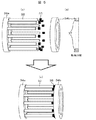
図2は、実施形態1の非磁性バーと非磁性端部保持部材の構成を示す図である。 FIG. 2 is a diagram illustrating a configuration of a nonmagnetic bar and a nonmagnetic end holding member according to the first embodiment.
図2(a)に示すように、非磁性バー32の一方の端部は、第1の非磁性端部保持部材34aと一体形成もしくはねじ止め等により強固に構成されている。非磁性バー32の他方の端部には絶縁部材35が配置され、図2(b)に示す第2の非磁性端部保持部材34bと非磁性バー32との間が電気的に絶縁される。そして図3(c)に示すように非磁性バー32と第2の非磁性端部保持部材34bは絶縁部材35を介して固定される。
As shown in FIG. 2 (a), one end of the
両者を電気的に絶縁しつつ固定する方法としては、例えば、非磁性バー32と非磁性端部保持部材34bの接触部に絶縁部材35をはさんだ後にモールドする方法が考えられる。
As a method of fixing the two while being electrically insulated, for example, a method of molding after sandwiching the insulating
また、モールド部材が絶縁部材35を兼ね、全体をモールドする方法を用いることもできるし、非磁性バー32と非磁性端部保持部材34bの接触部に絶縁部材35をはさんだ後に非導電性のねじにて固定する方法、あるいは、非磁性バー32と非磁性端部保持部材34bを接着剤にて接着する方法などを用いてもよい。例えば、本実施例では、磁性極片31と非磁性バー32は非磁性ケース33により一体化する構造を想定しており、この場合、非磁性ケース33の材質を樹脂モールドで構成することによりモールド部材が絶縁部材35を兼ね、変調磁極3を簡便に構成できる。
Further, the molding member can also serve as the
なお、第2の非磁性端部保持部材34bがなくても強度が保てる場合は第2の非磁性端部保持部材34bを用いなくとも良い。
If the strength can be maintained without the second nonmagnetic
非磁性バー32や第1および第2の非磁性端部保持部材34a,34bの材質は、非磁性ステンレス,チタン,アルミニウム,真鍮,銅などの非磁性金属、あるいはFRP,炭素繊維,ガラス繊維,樹脂モールドなどで構成される。
The
磁性極片31は、非磁性バー32と非磁性ケース33により一体化されており、さらに非磁性バー32は第1の非磁性端部保持部材34aと一体形成もしくはねじ止め等により強固に構成されているため、磁性極片31に働くトルクや応力などの力に対して耐性を持つ。
The
非磁性バー32の一方の端部は、第1の非磁性端部保持部材34aと一体形成もしくはねじ止め等により接続しているが、他方の端部は第2の非磁性端部保持部材34bと電気的に絶縁されているため、非磁性バーと非磁性端部保持部材を還流する電流ループを作らない。したがって非磁性バー32に交番磁界が発生しても、単一のバー内を還流する小さい電流が発生するだけであり、非磁性バーの渦電流損失を大幅に抑えることができる。
One end of the
ここで、第1および第2の非磁性端部保持部材34a,34bはいずれも非磁性体であるため、磁気歯車の軸方向外部に配置されても、それが原因で磁束が漏れることはなく、トルク伝達特性を低下させることはない。
Here, since the first and second nonmagnetic
〔実施形態2〕
次に、本発明の第2の実施形態について図1と図3を用いて説明する。なお、本発明の磁気歯車の断面図は図1と同じである。
[Embodiment 2]
Next, a second embodiment of the present invention will be described with reference to FIGS. The sectional view of the magnetic gear of the present invention is the same as FIG.
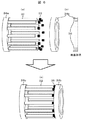
図3は、実施形態2の非磁性バーと非磁性端部保持部材の構成を示す図である。 FIG. 3 is a diagram illustrating a configuration of a nonmagnetic bar and a nonmagnetic end holding member according to the second embodiment.
図3(a)に示すように、複数の非磁性バー32のうち約半数のバーの一方の端部は、第1の非磁性端部保持部材34aと一体形成もしくはねじ止め等により強固に構成される。
As shown in FIG. 3A, one end of about half of the plurality of
同様に、図3(b)に示すように、残りの約半数のバーの一方の端部は、第2の非磁性端部保持部材34bと一体形成もしくはねじ止め等により強固に構成されている。
Similarly, as shown in FIG. 3 (b), one end of the remaining half of the bars is firmly formed by being integrally formed with the second non-magnetic
非磁性バー32の他方の端部には絶縁部材35が配置されている。
An insulating
図3(c)に示すように、端部保持部材と接続していない方のバー端部が他方の端部保持部材に互いに向き合い、両者の間に絶縁部材35が配置され、電気的に絶縁されている。両者を電気的に絶縁しつつ固定する方法は実施形態1に示した通りである。
As shown in FIG. 3 (c), the end of the bar that is not connected to the end holding member faces the other end holding member, and an insulating
非磁性バー32や第1および第2の非磁性端部保持部材34a,34bの材質は、実施形態1に示した通りである。
The materials of the
磁性極片31は非磁性バー32と非磁性ケース33により一体化されており、さらに非磁性バー32の半数は第1の非磁性端部保持部材34aと一体形成もしくはねじ止め等により強固に構成され、残りの非磁性バー32は第2の非磁性端部保持部材34bと一体形成もしくはねじ止め等により強固に構成されているため、磁性極片31に働くトルクや応力などの力に対して耐性を持つ。
The
非磁性バー32の一方の端部は、第1の非磁性端部保持部材34aもしくは第2の非磁性端部保持部材34bと一体形成もしくはねじ止め等により接続しているが、他方の端部は電気的に絶縁されているため、非磁性バーと非磁性端部保持部材を還流する電流ループを作らない。したがって非磁性バー32に交番磁界が発生しても、単一のバー内を還流する小さい電流が発生するだけであり、非磁性バーの渦電流損失を大幅に抑えることができる。
One end of the
なお、図3では非磁性バー1本おきに、バーの半数が一方の非磁性端部保持部材と一体形成し、残りの半数のバーを他方の非磁性端部保持部材と一体形成した例を示したが、例えば、交互に1本おきにかみ合わせるように構成しようとすると、製造中にバー自体が物理的干渉を起こしやすくなる可能性もあり、必ずしも半数ごと、あるいは、1本おきである必要はなく、設計思想に合わせて製造すればよい。また、非磁性バーの本数は偶数であっても奇数であってもよい。 In FIG. 3, every other non-magnetic bar, half of the bars are formed integrally with one non-magnetic end holding member, and the other half of the bars are formed integrally with the other non-magnetic end holding member. As shown, for example, if it is configured to alternately engage every other bar, the bar itself may easily cause physical interference during manufacturing, and it is not necessarily half or every other bar. It is not necessary, and it may be manufactured according to the design concept. Further, the number of nonmagnetic bars may be even or odd.
〔実施形態3〕
次に、本発明の第3の実施形態について図1と図4を用いて説明する。なお、本発明の磁気歯車の断面図は図1と同じである。
[Embodiment 3]
Next, a third embodiment of the present invention will be described with reference to FIGS. The sectional view of the magnetic gear of the present invention is the same as FIG.
図4は、実施形態3の非磁性バーと非磁性端部保持部材の構成を示す図である。 FIG. 4 is a diagram illustrating a configuration of a nonmagnetic bar and a nonmagnetic end holding member according to the third embodiment.
図4(a)に示すように、非磁性バー32の一方の端部は、第1の非磁性端部保持部材34aと一体形成もしくはねじ止め等により強固に構成されている。非磁性バー32の他方の端部には絶縁部材35が配置され、図4(b)に示す第2の非磁性端部保持部材34bと非磁性バー32との間が電気的に絶縁される。そして図4(b)に示すように、第2の非磁性端部保持部材34bの表面のうち、非磁性バーと電気的に絶縁して構成する部分にバーとほぼ同形状の窪み36を設け、その窪みに絶縁部材35を入れてバーをはめ込むことで、図4(c)に示すようにバーと端部保持部材を電気的に絶縁しつつバーを固定することができる。また、実施形態1に示した方法で、両者を電気的に絶縁しつつ固定することもできる。
As shown in FIG. 4 (a), one end of the
非磁性バー32や第1および第2の非磁性端部保持部材34a,34bの材質は、実施形態1に示した通りである。
The materials of the
磁性極片31は非磁性バー32と非磁性ケース33により一体化されており、さらに非磁性バー32の一方の端部は第1の非磁性端部保持部材34aと一体形成もしくはねじ止め等により強固に構成されており、さらに他方の端部は第2の非磁性端部保持部材34bの窪み36に電気的な絶縁部材35を介してはめ込んでいるため、磁性極片31に働くトルクや応力、さらには遠心力などに対して大きな耐性を持つ。
The
非磁性バー32の一方の端部は、第1の非磁性端部保持部材34aと一体形成もしくはねじ止め等により接続しているが、他方の端部は第2の非磁性端部保持部材34bと電気的に絶縁されているため、非磁性バーと非磁性端部保持部材を還流する電流ループを作らない。したがって非磁性バー32に交番磁界が発生しても、単一のバー内を還流する小さい電流が発生するだけであり、非磁性バーの渦電流損失を大幅に抑えることができる。
One end of the
なお、図4では全ての非磁性バーが第1の非磁性端部保持部材と一体形成された例を示したが、実施形態2に示したように一部の非磁性バーが第1の非磁性端部保持部材と一体形成され、残りの非磁性バーが第2の非磁性端部保持部材と一体形成されていてもよく、その場合は第2の非磁性端部保持部材34bにも窪みを設けることで、さらに強度を向上できる。
FIG. 4 shows an example in which all the nonmagnetic bars are integrally formed with the first nonmagnetic end holding member. However, as shown in the second embodiment, some of the nonmagnetic bars are the first nonmagnetic bars. The non-magnetic bar may be formed integrally with the magnetic end holding member, and the remaining non-magnetic bar may be formed integrally with the second non-magnetic end holding member. In this case, the second non-magnetic
〔実施形態4〕
次に、本発明の第4の実施形態について図1と図5を用いて説明する。なお、本発明の磁気歯車の断面図は図1と同じである。
[Embodiment 4]
Next, the 4th Embodiment of this invention is described using FIG. 1 and FIG. The sectional view of the magnetic gear of the present invention is the same as FIG.
図5は、実施形態4の非磁性バーと非磁性端部保持部材の構成を示す図である。 FIG. 5 is a diagram illustrating a configuration of a nonmagnetic bar and a nonmagnetic end holding member according to the fourth embodiment.
図5(a)に示すように、非磁性バー32の一方の端部は、第1の非磁性端部保持部材34aと一体形成もしくはねじ止め等により強固に構成されている。非磁性バー32の他方の端部には絶縁部材35が配置され、図5(b)に示す第2の非磁性端部保持部材34bと非磁性バー32との間が電気的に絶縁される。そして図5(b)に示すように、第2の非磁性端部保持部材34bの表面のうち、非磁性バーと電気的に絶縁して構成する部分に、内周側から外周側に向かって徐々に厚くなるようにテーパ37を設け、非磁性バー32と非磁性端部保持部材34bの間に絶縁部材35をはさんでバーをはめ込むことで、図5(c)に示すように、バーと端部保持部材を電気的に絶縁しつつバーに働く遠心力に対して耐性を持たせることができる。また、実施形態1に示した方法で、両者を電気的に絶縁しつつ固定することもできる。
As shown in FIG. 5 (a), one end of the
非磁性バー32や第1および第2の非磁性端部保持部材34a,34bの材質は、実施形態1に示した通りである。
The materials of the
磁性極片31は、非磁性バー32と非磁性ケース33により一体化されており、さらに非磁性バー32の一方の端部は第1の非磁性端部保持部材34aと一体形成もしくはねじ止め等により強固に構成されており、さらに他方の端部は第2の非磁性端部保持部材34bのテーパ37に電気的な絶縁部材35を介してはめ込んでいるため、磁性極片31に働くトルクや応力、さらには遠心力などに対して大きな耐性を持つ。
The
非磁性バー32の一方の端部は、第1の非磁性端部保持部材34aと一体形成もしくはねじ止め等により接続しているが、他方の端部は第2の非磁性端部保持部材34bと電気的に絶縁されているため、非磁性バーと非磁性端部保持部材を還流する電流ループを作らない。したがって非磁性バー32に交番磁界が発生しても、単一のバー内を還流する小さい電流が発生するだけであり、非磁性バーの渦電流損失を大幅に抑えることができる。
One end of the
なお、図5では全ての非磁性バーが第1の非磁性端部保持部材と一体形成された例を示したが、実施形態2に示したように一部の非磁性バーが第1の非磁性端部保持部材と一体形成され、残りの非磁性バーが第2の非磁性端部保持部材と一体形成されていてもよく、その場合は第2の非磁性端部保持部材34bにもテーパを設けることで、さらに強度を向上できる。
FIG. 5 shows an example in which all the nonmagnetic bars are integrally formed with the first nonmagnetic end holding member. However, as shown in the second embodiment, some of the nonmagnetic bars are the first nonmagnetic bars. The non-magnetic bar may be formed integrally with the magnetic end holding member, and the remaining non-magnetic bar may be formed integrally with the second non-magnetic end holding member. In this case, the second non-magnetic
これにより、回転時の遠心力による構造分解を防ぐことができる。ここで、構造分解とは、回転遠心力により、非磁性バー32,絶縁部材35又は非磁性端部保持部材34bが接触しなくなり、バラバラになる状態を意味する。
Thereby, the structure decomposition | disassembly by the centrifugal force at the time of rotation can be prevented. Here, the structural decomposition means a state in which the
〔実施形態5〕
次に、本発明の第5の実施形態について図1と図6を用いて説明する。なお、本発明の磁気歯車の断面図は図1と同じである。
[Embodiment 5]
Next, a fifth embodiment of the present invention will be described with reference to FIGS. The sectional view of the magnetic gear of the present invention is the same as FIG.
図6は、実施形態5の非磁性バーと非磁性端部保持部材の構成を示す図である。 FIG. 6 is a diagram illustrating a configuration of a nonmagnetic bar and a nonmagnetic end holding member according to a fifth embodiment.
図6(a)に示すように、非磁性バー32の一方の端部は、第1の非磁性端部保持部材34aと一体形成もしくはねじ止め等により強固に構成されている。非磁性バー32の他方の端部には絶縁部材35が配置され、図6(b)に示す第2の非磁性端部保持部材34bと非磁性バー32との間が電気的に絶縁される。そして図6(b)に示すように、第2の非磁性端部保持部材34bの表面のうち、非磁性バーと電気的に絶縁して構成する面の最外周部に突起38を設け、非磁性バー32と非磁性端部保持部材34bの間に絶縁部材35をはさんでバーをはめ込むことで、図6(c)に示すように、バーと端部保持部材を電気的に絶縁しつつバーに働く遠心力に対して耐性を持たせることができる。また、実施形態1に示した方法で、両者を電気的に絶縁しつつ固定することもできる。
As shown in FIG. 6 (a), one end of the
非磁性バー32や第1および第2の非磁性端部保持部材34a,34bの材質は、実施形態1に示した通りである。
The materials of the
磁性極片31は非磁性バー32と非磁性ケース33により一体化されており、さらに非磁性バー32の一方の端部は第1の非磁性端部保持部材34aと一体形成もしくはねじ止め等により強固に構成されており、さらに他方の端部は第2の非磁性端部保持部材34bの最外周部の突起38の内側に電気的な絶縁部材35を介してはめ込んでいるため、磁性極片31に働くトルクや応力、さらには遠心力などに対して大きな耐性を持つ。
The
非磁性バー32の一方の端部は、第1の非磁性端部保持部材34aと一体形成もしくはねじ止め等により接続しているが、他方の端部は第2の非磁性端部保持部材34bと電気的に絶縁されているため、非磁性バーと非磁性端部保持部材を還流する電流ループを作らない。したがって非磁性バー32に交番磁界が発生しても、単一のバー内を還流する小さい電流が発生するだけであり、非磁性バーの渦電流損失を大幅に抑えることができる。
One end of the
なお、図6では全ての非磁性バーが第1の非磁性端部保持部材と一体形成された例を示したが、実施形態2に示したように一部の非磁性バーが第1の非磁性端部保持部材と一体形成され、残りの非磁性バーが第2の非磁性端部保持部材と一体形成されていてもよく、その場合は第2の非磁性端部保持部材34bの最外周部にも突起を設けることで、さらに強度を向上できる。当該突起形状により、上記実施例4のテーパ構造より確実に回転時の遠心力による構造分解を防ぐことができる。
FIG. 6 shows an example in which all the nonmagnetic bars are integrally formed with the first nonmagnetic end holding member. However, as shown in the second embodiment, some of the nonmagnetic bars are the first nonmagnetic bars. The non-magnetic bar may be formed integrally with the magnetic end holding member, and the remaining non-magnetic bar may be formed integrally with the second non-magnetic end holding member. In this case, the outermost periphery of the second non-magnetic
〔実施形態6〕
次に、本発明の第6の実施形態について図7を用いて説明する。
[Embodiment 6]
Next, a sixth embodiment of the present invention will be described with reference to FIG.
図7は、本発明の実施形態6の磁気歯車の1/4断面図である。図1と異なる点は、図1では円形だった非磁性バー32の断面形状が、図7では径方向に短く周方向に長い偏平な長方形の断面形状を持つ非磁性バー32aとなっている点である。さらに非磁性バー32aは、変調磁極3の外周側と内周側の中間に位置して構成されている。
FIG. 7 is a quarter cross-sectional view of the magnetic gear according to the sixth embodiment of the present invention. The difference from FIG. 1 is that the cross-sectional shape of the
非磁性バー32aを径方向に短く周方向に長い偏平な長方形の断面形状とし、外周側と内周側の中間位置に構成したことによって、第1の永久磁石界磁1および第2の永久磁石界磁2から最も離れた位置に非磁性バーの表面を配置できるため、非磁性バーに発生する渦電流損を低減できる。
The
なお、非磁性バー32aと非磁性端部保持部材の構成は、実施形態1〜実施形態5に示した方法などによる。また、非磁性バー32aの断面形状は径方向に短く周方向に長い偏平な形状であれば、長方形に限らず台形や楕円形などでもよく、バーの強度や作り易さ等を考えた上で設計思想に合わせて製造すればよい。
The configuration of the
〔実施形態7〕
次に、本発明の第7の実施形態について図8を用いて説明する。
[Embodiment 7]
Next, a seventh embodiment of the present invention will be described with reference to FIG.
図8(a)は、本発明の実施形態7の磁気歯車の1/4断面図である。図7と異なる点は、図7では径方向に短く周方向に長い偏平な長方形の断面形状だった非磁性バー32aが、図8(a)では逆に径方向に長く周方向に短い偏平な長方形の断面形状を持つ非磁性バー32bとなっている点である。さらに非磁性バー32bは、隣接する磁性極片31の中間に位置して構成されている。
FIG. 8A is a quarter cross-sectional view of the magnetic gear according to the seventh embodiment of the present invention. 7 differs from FIG. 7 in that the
非磁性バー32bを径方向に長く周方向に短い偏平な長方形の断面形状としたことで、図8(b)に示すように渦電流のループする面積を小さくできるため、非磁性バーに発生する渦電流損を低減できる。また、隣接する磁性極片の中間位置に非磁性バーを構成したことによって、非磁性バーを貫通する磁束密度を小さくでき、非磁性バーに発生する渦電流損を低減できる。
Since the
なお、非磁性バー32bと非磁性端部保持部材の構成は、実施形態1〜実施形態5に示した方法などによる。また、非磁性バー32bの断面形状は径方向に長く周方向に短い偏平な形状であれば、長方形に限らず台形や楕円形などでもよく、バーの強度や作り易さ等を考えた上で設計思想に合わせて製造すればよい。
The configuration of the
〔実施形態8〕
次に、本発明の第8の実施形態について図9を用いて説明する。
[Embodiment 8]
Next, an eighth embodiment of the present invention will be described with reference to FIG.
図9は、本発明の実施形態8の磁気歯車の1/4断面図である。図7と異なる点は、図7では径方向に短く周方向に長い偏平な長方形の断面形状だった非磁性バー32aが、図9では径方向に短く周方向に長い偏平な長方形の周方向両端部に径方向に長く周方向に短い偏平な長方形が付き、アルファベットの“H”のような断面形状を持つ非磁性バー32cとなっている点である。
FIG. 9 is a quarter cross-sectional view of the magnetic gear according to the eighth embodiment of the present invention. 7 differs from FIG. 7 in that the
非磁性バー32cをアルファベットの“H”のような断面形状としたことで、径方向にかかる力と周方向にかかる力のいずれに対しても広い面で受けることができ、変調磁極3の強度を向上できる。また、第1の永久磁石界磁1および第2の永久磁石界磁2から最も離れた位置に非磁性バーの広い表面を配置できるため、非磁性バーに発生する渦電流損を低減できる。
Since the
なお、非磁性バー32cと非磁性端部保持部材の構成は、実施形態1〜実施形態5に示した方法などによる。また、非磁性バー32cの断面形状はアルファベットの“H”形ではなく“I”形などでもよく、バーの強度や作り易さ等を考えた上で設計思想に合わせて製造すればよい。
The configuration of the
〔その他の実施形態〕
なお、これまでの説明では、回転軸の外周方向にエアギャップを持つラジアルギャップ型磁気歯車を用いて説明したが、他の形式(例えば、回転軸の軸方向にエアギャップを持つアキシャルギャップ型や、直線駆動するリニア型など)に関しても、同様に実現可能である。
[Other Embodiments]
In the above description, a radial gap type magnetic gear having an air gap in the outer peripheral direction of the rotating shaft has been described. However, other types (for example, an axial gap type having an air gap in the axial direction of the rotating shaft, It is also possible to realize a linear type that drives linearly).
なお、上記実施例で述べてきた磁気ギヤと回転電機(モータ)を一体成形してもよい。この場合、例えば、バックヨーク22より内部にステータ鉄心を設けるよう構成したり、また、第1の永久磁石界磁1の外側にステータ鉄心を設けるよう構成してもよい。
The magnetic gear and the rotating electrical machine (motor) described in the above embodiment may be integrally formed. In this case, for example, a stator iron core may be provided inside the
1 第1の永久磁石界磁
2 第2の永久磁石界磁
3 変調磁極
11a,11b,21a,21b 永久磁石磁極
12,22 バックヨーク
31 磁性極片
32,32a,32b,32c 非磁性バー
33 非磁性ケース
34a 第1の非磁性端部保持部材
34b 第2の非磁性端部保持部材
35 絶縁部材
36 窪み
37 テーパ
38 突起
DESCRIPTION OF
Claims (10)
前記複数の磁性極片の間に非磁性バーを備え、前記非磁性バーの一方の端部が第1の非磁性端部保持部材と接続され、前記非磁性バーの他方の端部を第2の非磁性端部保持部材と電気的に絶縁して構成することを特徴とする磁気歯車装置。 A first permanent magnet field having a plurality of permanent magnet magnetic poles; a second permanent magnet field having a plurality of permanent magnet magnetic poles having a number of poles different from the first permanent magnet field; Magnetic field having a plurality of magnetic pole pieces between a permanent magnet field and the second permanent magnet field, and a modulation magnetic pole for modulating the number of poles of the first and second permanent magnet fields In gears,
A non-magnetic bar is provided between the plurality of magnetic pole pieces, one end of the non-magnetic bar is connected to a first non-magnetic end holding member, and the other end of the non-magnetic bar is a second end. A magnetic gear device characterized in that it is electrically insulated from the nonmagnetic end holding member.
前記非磁性バーのうち略半数の非磁性バーの一方の端部が、第1の非磁性端部保持部材と接続し、残りの非磁性バーの一方の端部を第2の非磁性端部保持部材と接続するように構成したことを特徴とする磁気歯車装置。 The magnetic gear device according to claim 1,
One end of approximately half of the nonmagnetic bars is connected to the first nonmagnetic end holding member, and one end of the remaining nonmagnetic bar is connected to the second nonmagnetic end. A magnetic gear device configured to be connected to a holding member.
前記非磁性端部保持部材の表面のうち、前記非磁性バーと電気的に絶縁して構成する部分に、前記非磁性バーの断面形状と略同形状の窪みを設け、該窪みに電気的な絶縁部材を介して前記非磁性バーをはめ込むことを特徴とする磁気歯車装置。 The magnetic gear device according to claim 1,
A portion of the surface of the nonmagnetic end holding member that is electrically insulated from the nonmagnetic bar is provided with a recess having substantially the same shape as the cross section of the nonmagnetic bar. A magnetic gear device, wherein the nonmagnetic bar is fitted through an insulating member.
前記非磁性端部保持部材の表面のうち、前記非磁性バーと電気的に絶縁して構成する部分を、内周側から外周側に向かって徐々に厚くなるように構成することを特徴とする磁気歯車装置。 The magnetic gear device according to claim 1,
A portion of the surface of the nonmagnetic end holding member that is electrically insulated from the nonmagnetic bar is configured to gradually increase from the inner peripheral side toward the outer peripheral side. Magnetic gear device.
前記非磁性端部保持部材の表面のうち、前記非磁性バーと電気的に絶縁して構成する面の最外周部に突起を設けることを特徴とする磁気歯車装置。 The magnetic gear device according to claim 1,
A magnetic gear device, wherein a protrusion is provided on an outermost peripheral portion of a surface of the surface of the nonmagnetic end holding member that is electrically insulated from the nonmagnetic bar.
前記非磁性バーの、前記第1の永久磁石界磁側から前記第2の永久磁石界磁側へ向けた長さを、前記磁性極片の、前記第1の永久磁石界磁側から前記第2の永久磁石界磁側へ向けた長さよりも短くし、
前記非磁性バーを前記第1の永久磁石界磁と前記第2の永久磁石界磁との間の略中間位置に配置することを特徴とする磁気歯車装置。 The magnetic gear device according to claim 1,
The length of the nonmagnetic bar from the first permanent magnet field side to the second permanent magnet field side is set to the length of the magnetic pole piece from the first permanent magnet field side to the second permanent magnet field side. 2 shorter than the length toward the permanent magnet field side,
A magnetic gear device, wherein the nonmagnetic bar is disposed at a substantially intermediate position between the first permanent magnet field and the second permanent magnet field.
前記非磁性バーの、近接する一方の磁性極片側から近接する他方の磁性極片側へ向けた長さを、前記両磁性極片間の長さよりも短くし、前記非磁性バーを前記一方の磁性極片と前記他方の磁性極片との間の略中間位置に配置することを特徴とする磁気歯車装置。 The magnetic gear device according to claim 1,
The length of the nonmagnetic bar from the one adjacent magnetic pole piece side to the other adjacent magnetic pole piece side is made shorter than the length between the two magnetic pole pieces, and the nonmagnetic bar is moved to the one magnetic pole piece side. A magnetic gear device, wherein the magnetic gear device is disposed at a substantially intermediate position between the pole piece and the other magnetic pole piece.
前記非磁性バーの断面形状をアルファベットの“H”もしくは“I”のような形状とすることを特徴とする磁気歯車装置。 The magnetic gear device according to claim 1,
A magnetic gear device characterized in that the cross-sectional shape of the non-magnetic bar is a shape such as alphabet "H" or "I".
前記非磁性バーと前記磁性極片を、樹脂でモールドして一体構成することを特徴とする磁気歯車装置。 The magnetic gear device according to claim 1,
A magnetic gear device, wherein the nonmagnetic bar and the magnetic pole piece are integrally formed by molding with resin.
Priority Applications (3)
| Application Number | Priority Date | Filing Date | Title |
|---|---|---|---|
| JP2011015896A JP5286373B2 (en) | 2011-01-28 | 2011-01-28 | Magnetic gear |
| US13/353,345 US8575804B2 (en) | 2011-01-28 | 2012-01-19 | Magnetic gear |
| CN201210020063.4A CN102624194B (en) | 2011-01-28 | 2012-01-21 | Magnetic gear |
Applications Claiming Priority (1)
| Application Number | Priority Date | Filing Date | Title |
|---|---|---|---|
| JP2011015896A JP5286373B2 (en) | 2011-01-28 | 2011-01-28 | Magnetic gear |
Publications (3)
| Publication Number | Publication Date |
|---|---|
| JP2012157205A JP2012157205A (en) | 2012-08-16 |
| JP2012157205A5 JP2012157205A5 (en) | 2012-12-27 |
| JP5286373B2 true JP5286373B2 (en) | 2013-09-11 |
Family
ID=46563918
Family Applications (1)
| Application Number | Title | Priority Date | Filing Date |
|---|---|---|---|
| JP2011015896A Expired - Fee Related JP5286373B2 (en) | 2011-01-28 | 2011-01-28 | Magnetic gear |
Country Status (3)
| Country | Link |
|---|---|
| US (1) | US8575804B2 (en) |
| JP (1) | JP5286373B2 (en) |
| CN (1) | CN102624194B (en) |
Cited By (6)
| Publication number | Priority date | Publication date | Assignee | Title |
|---|---|---|---|---|
| WO2021131807A1 (en) | 2019-12-24 | 2021-07-01 | 三菱重工業株式会社 | Magnetic pole-piece device and magnetic gear device |
| WO2021145264A1 (en) | 2020-01-17 | 2021-07-22 | 三菱重工業株式会社 | Electric vehicle |
| WO2021149720A1 (en) | 2020-01-24 | 2021-07-29 | 三菱重工業株式会社 | Pole shoe device, magnetic gear, magnetic geared motor, and magnetic geared electric generator |
| WO2021149722A1 (en) | 2020-01-24 | 2021-07-29 | 三菱重工業株式会社 | Outer diameter-side magnet field and magnetic gear |
| WO2021149603A1 (en) | 2020-01-24 | 2021-07-29 | 三菱重工業株式会社 | Magnetic pole-piece device and magnetic gear |
| WO2021210119A1 (en) | 2020-04-16 | 2021-10-21 | 三菱電機株式会社 | Magnetic-geared motor |
Families Citing this family (30)
| Publication number | Priority date | Publication date | Assignee | Title |
|---|---|---|---|---|
| JP5408355B2 (en) * | 2010-07-29 | 2014-02-05 | 日立金属株式会社 | Magnetic gear device and holding member |
| JP5958466B2 (en) * | 2011-07-15 | 2016-08-02 | 日立金属株式会社 | Magnetic gear device |
| CN104221269B (en) * | 2012-03-27 | 2017-07-25 | 日立金属株式会社 | Frequency conversion apparatus |
| DE102012206345A1 (en) * | 2012-03-28 | 2013-10-02 | Siemens Aktiengesellschaft | Magnetic reluctance coupling with two rotors |
| JP6020598B2 (en) * | 2013-01-11 | 2016-11-02 | 日立金属株式会社 | Magnetic gear device |
| US9370982B2 (en) | 2013-12-16 | 2016-06-21 | GM Global Technology Operations LLC | Method and apparatus for suspension damping including negative stiffness |
| US9133900B2 (en) | 2013-12-16 | 2015-09-15 | GM Global Technology Operations LLC | Method and apparatus for suspension damping including negative stiffness employing a permanent magnet |
| US9365089B2 (en) | 2013-12-16 | 2016-06-14 | GM Global Technology Operations LLC | Method and apparatus for active suspension damping including negative stiffness |
| JP6257114B2 (en) * | 2014-05-20 | 2018-01-10 | 株式会社Ihi | Magnetic wave gear device |
| DE102014212067A1 (en) * | 2014-06-24 | 2015-12-24 | Mahle International Gmbh | vehicle |
| JP6403329B2 (en) * | 2015-01-20 | 2018-10-10 | 株式会社Ihi | Magnetic wave gear device |
| JP6576800B2 (en) * | 2015-09-07 | 2019-09-18 | Ntn株式会社 | Magnetic gear unit |
| WO2017043387A1 (en) * | 2015-09-07 | 2017-03-16 | Ntn株式会社 | Magnetic gear device |
| CN105262317B (en) * | 2015-09-30 | 2018-06-29 | 中国科学院宁波材料技术与工程研究所 | Cam mechanism |
| GB2549448A (en) * | 2016-01-13 | 2017-10-25 | Magnomatics Ltd | A magnetically geared apparatus |
| EP3261238B1 (en) * | 2016-06-23 | 2020-08-12 | Goodrich Actuation Systems Limited | Magnetic gear |
| CN106533120B (en) * | 2016-10-15 | 2019-12-03 | 哈尔滨工业大学 | A kind of reluctance type magnetism face gear group for quadrature axis transmission |
| JP6902755B2 (en) * | 2017-12-01 | 2021-07-14 | 東洋機械株式会社 | Magnet structure |
| CN108418391B (en) * | 2018-05-02 | 2023-09-29 | 盐城永安科技有限公司 | Completely-spliced magnetic gear modulation ring and splicing method thereof |
| CN108365733B (en) * | 2018-05-02 | 2023-09-29 | 盐城永安科技有限公司 | Magnetic gear structure capable of improving production efficiency |
| CN108429430B (en) * | 2018-05-02 | 2023-09-29 | 盐城永安科技有限公司 | Modulation type permanent magnet gear |
| CN108448869B (en) * | 2018-05-02 | 2023-09-26 | 盐城永安科技有限公司 | Modulation ring of modulation type permanent magnet gear and manufacturing method thereof |
| KR102270090B1 (en) * | 2018-05-15 | 2021-06-28 | 한국전기연구원 | Pole piece assembly, method for manufacturing the same and magnetic gear having the same |
| JP7346312B2 (en) * | 2020-01-16 | 2023-09-19 | 三菱重工業株式会社 | Magnetic geared rotating electric machine and manufacturing method. |
| CN111245195B (en) * | 2020-03-03 | 2021-11-02 | 东南大学 | Brushless power feedback type permanent magnet speed regulator with squirrel cage conductor rotor |
| WO2022030031A1 (en) * | 2020-08-03 | 2022-02-10 | 三菱電機株式会社 | Magnetic flux modulation-type magnetic gear |
| US11271466B1 (en) | 2020-09-09 | 2022-03-08 | Anthony A. Gallistel | Magnetic gearing component having a magnetic core with helical endcaps |
| US20230387775A1 (en) * | 2020-12-02 | 2023-11-30 | Panasonic Intellectual Property Management Co., Ltd. | Magnetic-geared motor and magnetic gear |
| GB2607870A (en) * | 2021-06-07 | 2022-12-21 | Magnomatics Ltd | Magnetically geared apparatus and rotor |
| JP2024044295A (en) * | 2022-09-21 | 2024-04-02 | 三菱重工業株式会社 | Pole piece rotor and magnetic gear electric machine |
Family Cites Families (11)
| Publication number | Priority date | Publication date | Assignee | Title |
|---|---|---|---|---|
| CA1292763C (en) * | 1988-12-07 | 1991-12-03 | Patrick M. Taiani | Low loss magnetic drive system |
| DE4405701A1 (en) * | 1994-02-23 | 1995-08-24 | Philips Patentverwaltung | Magnetic gear with several magnetically interacting, relatively movable parts |
| GB0605356D0 (en) * | 2006-03-17 | 2006-04-26 | Rolls Royce Plc | A magnetic gearbox arrangement |
| GB2437568B (en) * | 2006-04-24 | 2009-02-11 | Univ Sheffield | Electrical machines |
| US7791235B2 (en) * | 2006-12-22 | 2010-09-07 | General Electric Company | Variable magnetic coupling of rotating machinery |
| GB2457226B (en) * | 2008-01-11 | 2013-01-09 | Magnomatics Ltd | Drives for sealed systems |
| GB0800463D0 (en) * | 2008-01-11 | 2008-02-20 | Magnomatics Ltd | Magnetic drive systems |
| GB2457682B (en) * | 2008-02-21 | 2012-03-28 | Magnomatics Ltd | Variable magnetic gears |
| US7804215B2 (en) * | 2008-09-30 | 2010-09-28 | General Electric Company | Integrated cooling concept for magnetically geared machine |
| JP5278812B2 (en) * | 2009-03-24 | 2013-09-04 | 日立金属株式会社 | Magnetic gear and manufacturing method thereof |
| US8188629B2 (en) * | 2010-03-03 | 2012-05-29 | Industrial Technology Research Institute | Magnetic transmission assembly |
-
2011
- 2011-01-28 JP JP2011015896A patent/JP5286373B2/en not_active Expired - Fee Related
-
2012
- 2012-01-19 US US13/353,345 patent/US8575804B2/en not_active Expired - Fee Related
- 2012-01-21 CN CN201210020063.4A patent/CN102624194B/en not_active Expired - Fee Related
Cited By (7)
| Publication number | Priority date | Publication date | Assignee | Title |
|---|---|---|---|---|
| WO2021131807A1 (en) | 2019-12-24 | 2021-07-01 | 三菱重工業株式会社 | Magnetic pole-piece device and magnetic gear device |
| WO2021145264A1 (en) | 2020-01-17 | 2021-07-22 | 三菱重工業株式会社 | Electric vehicle |
| WO2021149720A1 (en) | 2020-01-24 | 2021-07-29 | 三菱重工業株式会社 | Pole shoe device, magnetic gear, magnetic geared motor, and magnetic geared electric generator |
| WO2021149722A1 (en) | 2020-01-24 | 2021-07-29 | 三菱重工業株式会社 | Outer diameter-side magnet field and magnetic gear |
| WO2021149603A1 (en) | 2020-01-24 | 2021-07-29 | 三菱重工業株式会社 | Magnetic pole-piece device and magnetic gear |
| JP7413042B2 (en) | 2020-01-24 | 2024-01-15 | 三菱重工業株式会社 | Outer diameter side magnet field and magnetic gear |
| WO2021210119A1 (en) | 2020-04-16 | 2021-10-21 | 三菱電機株式会社 | Magnetic-geared motor |
Also Published As
| Publication number | Publication date |
|---|---|
| US8575804B2 (en) | 2013-11-05 |
| US20120194021A1 (en) | 2012-08-02 |
| CN102624194B (en) | 2014-08-27 |
| JP2012157205A (en) | 2012-08-16 |
| CN102624194A (en) | 2012-08-01 |
Similar Documents
| Publication | Publication Date | Title |
|---|---|---|
| JP5286373B2 (en) | Magnetic gear | |
| JP5723987B2 (en) | Magnetic gear type rotary electric machine | |
| JP4169055B2 (en) | Rotating electric machine | |
| US9083219B2 (en) | Rotor and motor | |
| JP5521820B2 (en) | Rotating electric machine and manufacturing method thereof | |
| JP5663936B2 (en) | Permanent magnet rotating electric machine | |
| JP5502571B2 (en) | Permanent magnet rotating electric machine | |
| US20070267929A1 (en) | Stator arrangement and rotor arrangement for a transverse flux machine | |
| WO2013098940A1 (en) | Electric motor | |
| CN105052015A (en) | Axial type rotating electrical machine | |
| JP2007330025A (en) | Motor | |
| JP2014155415A (en) | Embedded magnet rotor and method of manufacturing embedded magnet rotor | |
| JP2005328679A (en) | Permanent magnet reluctance type rotating electric machine | |
| JP2008278590A (en) | Rotary electric machine | |
| JP6121914B2 (en) | Synchronous motor | |
| CN111509883A (en) | Rotor assembly and axial magnetic field motor | |
| JP6112970B2 (en) | Permanent magnet rotating electric machine | |
| JP2008022664A (en) | Magnetic field element and rotating electric machine | |
| JP2006340556A (en) | Permanent magnet member for interior magnet-type rotary electric machine and rotary electric machine | |
| TWI385899B (en) | Rotor structure for permanent-magnet machines and manufacture method thereof | |
| JP4862556B2 (en) | Field element and rotating electric machine | |
| JP2011045198A (en) | Stator for axial-gap motor | |
| JP2011055584A (en) | Rotor for ipm motor | |
| JP6017885B2 (en) | Synchronous motor rotor | |
| JP2011083149A (en) | Rotor for embedded-magnet synchronous motor |
Legal Events
| Date | Code | Title | Description |
|---|---|---|---|
| RD04 | Notification of resignation of power of attorney |
Free format text: JAPANESE INTERMEDIATE CODE: A7424 Effective date: 20120522 |
|
| A521 | Request for written amendment filed |
Free format text: JAPANESE INTERMEDIATE CODE: A523 Effective date: 20121113 |
|
| A621 | Written request for application examination |
Free format text: JAPANESE INTERMEDIATE CODE: A621 Effective date: 20121113 |
|
| A977 | Report on retrieval |
Free format text: JAPANESE INTERMEDIATE CODE: A971007 Effective date: 20130424 |
|
| TRDD | Decision of grant or rejection written | ||
| A01 | Written decision to grant a patent or to grant a registration (utility model) |
Free format text: JAPANESE INTERMEDIATE CODE: A01 Effective date: 20130507 |
|
| A61 | First payment of annual fees (during grant procedure) |
Free format text: JAPANESE INTERMEDIATE CODE: A61 Effective date: 20130603 |
|
| LAPS | Cancellation because of no payment of annual fees |