JP5276173B2 - ROM list decoding of near codeword - Google Patents
ROM list decoding of near codeword Download PDFInfo
- Publication number
- JP5276173B2 JP5276173B2 JP2011522963A JP2011522963A JP5276173B2 JP 5276173 B2 JP5276173 B2 JP 5276173B2 JP 2011522963 A JP2011522963 A JP 2011522963A JP 2011522963 A JP2011522963 A JP 2011522963A JP 5276173 B2 JP5276173 B2 JP 5276173B2
- Authority
- JP
- Japan
- Prior art keywords
- stored
- node
- check
- nodes
- profile
- Prior art date
- Legal status (The legal status is an assumption and is not a legal conclusion. Google has not performed a legal analysis and makes no representation as to the accuracy of the status listed.)
- Expired - Fee Related
Links
Images


Classifications
-
- H—ELECTRICITY
- H03—ELECTRONIC CIRCUITRY
- H03M—CODING; DECODING; CODE CONVERSION IN GENERAL
- H03M13/00—Coding, decoding or code conversion, for error detection or error correction; Coding theory basic assumptions; Coding bounds; Error probability evaluation methods; Channel models; Simulation or testing of codes
- H03M13/03—Error detection or forward error correction by redundancy in data representation, i.e. code words containing more digits than the source words
- H03M13/05—Error detection or forward error correction by redundancy in data representation, i.e. code words containing more digits than the source words using block codes, i.e. a predetermined number of check bits joined to a predetermined number of information bits
- H03M13/11—Error detection or forward error correction by redundancy in data representation, i.e. code words containing more digits than the source words using block codes, i.e. a predetermined number of check bits joined to a predetermined number of information bits using multiple parity bits
- H03M13/1102—Codes on graphs and decoding on graphs, e.g. low-density parity check [LDPC] codes
- H03M13/1105—Decoding
- H03M13/1111—Soft-decision decoding, e.g. by means of message passing or belief propagation algorithms
-
- H—ELECTRICITY
- H03—ELECTRONIC CIRCUITRY
- H03M—CODING; DECODING; CODE CONVERSION IN GENERAL
- H03M13/00—Coding, decoding or code conversion, for error detection or error correction; Coding theory basic assumptions; Coding bounds; Error probability evaluation methods; Channel models; Simulation or testing of codes
- H03M13/03—Error detection or forward error correction by redundancy in data representation, i.e. code words containing more digits than the source words
- H03M13/05—Error detection or forward error correction by redundancy in data representation, i.e. code words containing more digits than the source words using block codes, i.e. a predetermined number of check bits joined to a predetermined number of information bits
- H03M13/11—Error detection or forward error correction by redundancy in data representation, i.e. code words containing more digits than the source words using block codes, i.e. a predetermined number of check bits joined to a predetermined number of information bits using multiple parity bits
- H03M13/1102—Codes on graphs and decoding on graphs, e.g. low-density parity check [LDPC] codes
- H03M13/1105—Decoding
- H03M13/1142—Decoding using trapping sets
-
- H—ELECTRICITY
- H03—ELECTRONIC CIRCUITRY
- H03M—CODING; DECODING; CODE CONVERSION IN GENERAL
- H03M13/00—Coding, decoding or code conversion, for error detection or error correction; Coding theory basic assumptions; Coding bounds; Error probability evaluation methods; Channel models; Simulation or testing of codes
- H03M13/37—Decoding methods or techniques, not specific to the particular type of coding provided for in groups H03M13/03 - H03M13/35
- H03M13/3707—Adaptive decoding and hybrid decoding, e.g. decoding methods or techniques providing more than one decoding algorithm for one code
-
- H—ELECTRICITY
- H03—ELECTRONIC CIRCUITRY
- H03M—CODING; DECODING; CODE CONVERSION IN GENERAL
- H03M13/00—Coding, decoding or code conversion, for error detection or error correction; Coding theory basic assumptions; Coding bounds; Error probability evaluation methods; Channel models; Simulation or testing of codes
- H03M13/37—Decoding methods or techniques, not specific to the particular type of coding provided for in groups H03M13/03 - H03M13/35
- H03M13/3738—Decoding methods or techniques, not specific to the particular type of coding provided for in groups H03M13/03 - H03M13/35 with judging correct decoding
-
- H—ELECTRICITY
- H03—ELECTRONIC CIRCUITRY
- H03M—CODING; DECODING; CODE CONVERSION IN GENERAL
- H03M13/00—Coding, decoding or code conversion, for error detection or error correction; Coding theory basic assumptions; Coding bounds; Error probability evaluation methods; Channel models; Simulation or testing of codes
- H03M13/37—Decoding methods or techniques, not specific to the particular type of coding provided for in groups H03M13/03 - H03M13/35
- H03M13/3746—Decoding methods or techniques, not specific to the particular type of coding provided for in groups H03M13/03 - H03M13/35 with iterative decoding
- H03M13/3753—Decoding methods or techniques, not specific to the particular type of coding provided for in groups H03M13/03 - H03M13/35 with iterative decoding using iteration stopping criteria
-
- H—ELECTRICITY
- H03—ELECTRONIC CIRCUITRY
- H03M—CODING; DECODING; CODE CONVERSION IN GENERAL
- H03M13/00—Coding, decoding or code conversion, for error detection or error correction; Coding theory basic assumptions; Coding bounds; Error probability evaluation methods; Channel models; Simulation or testing of codes
- H03M13/37—Decoding methods or techniques, not specific to the particular type of coding provided for in groups H03M13/03 - H03M13/35
- H03M13/45—Soft decoding, i.e. using symbol reliability information
- H03M13/451—Soft decoding, i.e. using symbol reliability information using a set of candidate code words, e.g. ordered statistics decoding [OSD]
-
- H—ELECTRICITY
- H03—ELECTRONIC CIRCUITRY
- H03M—CODING; DECODING; CODE CONVERSION IN GENERAL
- H03M13/00—Coding, decoding or code conversion, for error detection or error correction; Coding theory basic assumptions; Coding bounds; Error probability evaluation methods; Channel models; Simulation or testing of codes
- H03M13/03—Error detection or forward error correction by redundancy in data representation, i.e. code words containing more digits than the source words
- H03M13/05—Error detection or forward error correction by redundancy in data representation, i.e. code words containing more digits than the source words using block codes, i.e. a predetermined number of check bits joined to a predetermined number of information bits
- H03M13/09—Error detection only, e.g. using cyclic redundancy check [CRC] codes or single parity bit
Landscapes
- Physics & Mathematics (AREA)
- Probability & Statistics with Applications (AREA)
- Engineering & Computer Science (AREA)
- Theoretical Computer Science (AREA)
- Error Detection And Correction (AREA)
- Signal Processing For Digital Recording And Reproducing (AREA)
Description
本発明は、ディジタル信号処理に関し、具体的には、low−density parity check(LDPC)コーディングと称するデータ符号化方法に関する。 The present invention relates to digital signal processing, and more specifically to a data encoding method called low-density parity check (LDPC) coding.
通信は、送信器による、通信チャネルを介する受信器への情報の伝送である。実世界では、通信チャネルは、送信器から受信される情報のひずんだ版を受信器に出力する、雑音のある通信路である。ハード・ディスク(HD)ドライブは、送信器から情報を受け入れ、その情報を格納し、その後、おそらくは、その情報の多少ひずんだコピーを受信器に送る、1つのそのような雑音のある通信路である。 Communication is the transmission of information by a transmitter to a receiver via a communication channel. In the real world, a communication channel is a noisy channel that outputs a distorted version of the information received from the transmitter to the receiver. A hard disk (HD) drive accepts information from a transmitter, stores that information, and then perhaps one such noisy channel that sends a somewhat distorted copy of that information to the receiver. is there.
HDドライブなどの通信チャネルによって導入されるひずみは、チャネル・エラーすなわち、チャネル入力信号が0であった時に受信器がチャネル出力信号を1と解釈し、およびその逆を行う状況を引き起こすのに十分に大きい場合がある。チャネル・エラーは、スループットを下げ、したがって望ましくない。したがって、チャネル・エラーを検出し、かつ/または訂正するツールの継続する必要がある。low−density parity check(LDPC)コーディングは、チャネル・エラーを検出し、訂正する1つの方法である。LDPC符号は、低信号対雑音比(SNR)応用のための非常に低いビット誤り率(BER)を達成できる、既知のシャノン限界に近い符号の1つである。LDPC復号は、その並列性の可能性、低い実施複雑さ、短い復号待ち時間、ならびに高SNRでのより深刻でないエラーフロアによって区別される。LDPC符号は、事実上すべての次世代通信標準規格について検討されている。 The distortion introduced by a communication channel such as an HD drive is sufficient to cause a channel error, ie a situation where the receiver interprets the channel output signal as 1 when the channel input signal is 0 and vice versa. Can be great. Channel errors reduce throughput and are therefore undesirable. Therefore, there is a continuing need for tools to detect and / or correct channel errors. Low-density parity check (LDPC) coding is one method of detecting and correcting channel errors. The LDPC code is one of the codes close to the known Shannon limit that can achieve a very low bit error rate (BER) for low signal-to-noise ratio (SNR) applications. LDPC decoding is distinguished by its parallelism potential, low implementation complexity, short decoding latency, and less severe error floor at high SNR. LDPC codes are being considered for virtually all next generation communication standards.
ある種の実施形態で、本発明は、グラフベースの符号を使用して符号化された符号化されたデータを復号する方法を含む。この方法は、(a)候補の復号された符号語を生成するために、符号化されたデータを復号することと、(b)候補の復号された符号語が復号された正しい符号語ではない場合に、復号された正しい符号語を生成することを試みるためにトラッピング・セット(TS)−ROMリスト復号方法を実行することとを含む。候補の復号された符号語は、少なくとも1つの満足されないチェックノードを有し、満足されないチェックノードは、パリティ検査に合格しないチェックノードである。TS−ROMリスト復号方法は、ROMメモリ内に格納された1つまたは複数のTSプロファイルにアクセスする。第1の格納されたTSプロファイルは、少なくとも1つの満足されないチェック(USC)ノードの格納された情報および少なくとも1つの誤って満足されたチェック(MSC)ノードの格納された情報を含む。MSCノードは、(1)誤りのあるビットノード(EBN)に関連し、(2)パリティ検査を満足するチェックノードである。第2の格納されたTSプロファイルは、1つまたは複数のUSCノードおよび1つまたは複数のMSCノードを有するトラッピング・セットに関連し、第2の格納されたTSプロファイルは、1つまたは複数のUSCノードの格納された情報を含むが、1つまたは複数のMSCノードに関する情報を含まない。 In certain embodiments, the present invention includes a method for decoding encoded data that has been encoded using a graph-based code. This method includes: (a) decoding the encoded data to generate a candidate decoded codeword; and (b) the candidate decoded codeword is not the correct decoded codeword. And performing a trapping set (TS) -ROM list decoding method to attempt to generate the correct decoded codeword. The candidate decoded codeword has at least one unsatisfied check node, and the unsatisfied check node is a check node that does not pass the parity check. The TS-ROM list decoding method accesses one or more TS profiles stored in ROM memory. The first stored TS profile includes stored information of at least one unsatisfied check (USC) node and stored information of at least one falsely satisfied check (MSC) node. The MSC node is (1) a check node related to an erroneous bit node (EBN) and (2) satisfies a parity check. The second stored TS profile is associated with a trapping set having one or more USC nodes and one or more MSC nodes, and the second stored TS profile is one or more USCs. Contains stored information for the node but does not contain information about one or more MSC nodes.
他の実施形態で、本発明は、グラフベースの符号を使用して符号化された符号化されたデータを復号する装置である。この装置は、(a)候補の復号された符号語を生成するために、符号化されたデータを復号するように適合された復号器と、(b)候補の復号された符号語が復号された正しい符号語ではない場合に、復号された正しい符号語を生成することを試みるためにトラッピング・セット(TS)−ROMリスト復号方法を実行するように適合されたポストプロセッサとを含む。候補の復号された符号語は、少なくとも1つの満足されないチェックノードを有し、満足されないチェックノードは、パリティ検査に合格しないチェックノードである。TS−ROMリスト復号方法は、ROMメモリ内に格納された1つまたは複数のTSプロファイルにアクセスする。第1の格納されたTSプロファイルは、少なくとも1つの満足されないチェック(USC)ノードの格納された情報および少なくとも1つの誤って満足されたチェック(MSC)ノードの格納された情報を含む。MSCノードは、(1)誤りのあるビットノード(EBN)に関連し、(2)パリティ検査を満足するチェックノードである。第2の格納されたTSプロファイルは、1つまたは複数のUSCノードおよび1つまたは複数のMSCノードを有するトラッピング・セットに関連し、第2の格納されたTSプロファイルは、1つまたは複数のUSCノードの格納された情報を含むが、1つまたは複数のMSCノードに関する情報を含まない。 In another embodiment, the invention is an apparatus for decoding encoded data that has been encoded using a graph-based code. The apparatus includes: (a) a decoder adapted to decode the encoded data to generate a candidate decoded codeword; and (b) the candidate decoded codeword is decoded. A post-processor adapted to perform a trapping set (TS) -ROM list decoding method to attempt to generate a decoded correct codeword if it is not the correct codeword. The candidate decoded codeword has at least one unsatisfied check node, and the unsatisfied check node is a check node that does not pass the parity check. The TS-ROM list decoding method accesses one or more TS profiles stored in ROM memory. The first stored TS profile includes stored information of at least one unsatisfied check (USC) node and stored information of at least one falsely satisfied check (MSC) node. The MSC node is (1) a check node related to an erroneous bit node (EBN) and (2) satisfies a parity check. The second stored TS profile is associated with a trapping set having one or more USC nodes and one or more MSC nodes, and the second stored TS profile is one or more USCs. Contains stored information for the node but does not contain information about one or more MSC nodes.
本発明の他の態様、特徴、および利益は、次の詳細な説明、添付の特許請求の範囲、および添付図面からより十分に明らかになり、添付図面では、類似する符号が、類似するまたは同一の要素を識別する。 Other aspects, features, and advantages of the present invention will become more fully apparent from the following detailed description, the appended claims, and the accompanying drawings, in which like numerals are similar or identical. Identifies the element.
図1は、LDPCコーディングを利用する通常のハード・ディスク(HD)ドライブ100の一部のブロック図である。HDドライブ100は、プラッタ102および読取りチャネル104を含む。読取りチャネル104は、LDPC符号器106、書込みプロセッサ108、読取りプロセッサ110、およびLDPC復号器112を含む。経路114は、LDPC符号器106とLDPC復号器112との間の雑音のある通信路である。
FIG. 1 is a block diagram of a portion of a typical hard disk (HD)
プラッタ102に書き込まれる情報語は、LDPC符号語を作るためにLDPC符号器106によって処理される。LDPC符号語は、書込みプロセッサ108に送られ、書込みプロセッサ108は、複数のモジュール、たとえば、BPSK(二進移相変調)符号器、ディジタル−アナログ変換器などを含む。書込みプロセッサ108の出力116が、プラッタ102に書き込まれる。
Information words written to the
プラッタ102から読み取られた信号118は、読取りプロセッサ110に送られ、読取りプロセッサ110は、複数のモジュール、たとえば、前置増幅器、連続時間フィルタ、固定インパルス応答フィルタ、検出器、アナログ−ディジタル変換器などを含む。読取りプロセッサ110は、対数尤度比(LLR)値LchをLDPC復号器112に出力し、LDPC復号器112は、復号された情報語を出力する。さらに、LDPC復号器112は、ELDPC値を読取りプロセッサ110に送り返す。ELDPCは、下の式6によって定義され、中間の計算されたLLR値を表す。読取りプロセッサ110は、ELDPC値を使用して、その性能を調整し、これは、ターボ復号として知られるプロセスである。
The
LDPC符号化
LDPC符号器106は、情報語のビットに、LDPC符号によって指定される複数のパリティ・ビットを付加して、符号語を作る。情報語のビットは、可変ビットとして知られ、これらの可変ビットの個数は、Kと表される。あるLDPC符号語内のビットの総数は、Nと表される。したがって、パリティ・ビットの個数は、N−Kによって与えられる。特定のLDPC符号のレートは、K/Nすなわち、符号語長さに対する情報語長さの比である。したがって、9ビット符号語を作るために3ビット情報語のそれぞれに6つのパリティ・ビットを付加するLDPC符号は、1/3のレートを有する。通常のHDドライブの場合に、情報語長さKは、4096ビット(通常のHDドライブ・セクタの長さ)であり、パリティ・ビットの個数は、4506ビットの符号語長さおよび0.9のレートについて、約410ビットである。
LDPC Coding The LDPC encoder 106 adds a plurality of parity bits specified by the LDPC code to the bits of the information word to create a code word. The bits of the information word are known as variable bits, and the number of these variable bits is represented as K. The total number of bits in an LDPC codeword is denoted as N. Therefore, the number of parity bits is given by NK. The rate of a particular LDPC code is K / N, ie the ratio of information word length to codeword length. Thus, an LDPC code that adds 6 parity bits to each of the 3-bit information words to create a 9-bit codeword has a rate of 1/3. In the case of a normal HD drive, the information word length K is 4096 bits (the length of a normal HD drive sector), and the number of parity bits is 4506 bits of codeword length and 0.9. About 410 bits for the rate.
LDPC符号語内の各パリティ・ビットは、その特定のLDPC符号によって指定される特定の形でその符号語内の1つまたは複数の他の(可変またはパリティ)ビットに関連し、パリティ・ビットに割り当てられる値は、LDPC符号を満足するようにセットされる。通常のLDPC符号は、関連するビットがパリティ検査制約を満足する、たとえば、関連するビットの合計が偶数である、すなわち、合計modulo 2=0であることを指定する。 Each parity bit in an LDPC codeword is associated with one or more other (variable or parity) bits in that codeword in a particular form specified by that particular LDPC code, and The assigned value is set to satisfy the LDPC code. A normal LDPC code specifies that the relevant bits satisfy the parity check constraint, eg, the sum of the relevant bits is an even number, ie, the sum modulo 2 = 0.
LDPC符号
特定のLDPC符号は、パリティ検査行列またはH行列あるいは単純にHとして知られる1および0の2次元行列によって定義される。Hは、LDPC符号器とLDPC復号器との両方によって、先験的に既知である。Hは、N列N−K行を含む、すなわち、符号語のすべてのビットの列およびすべてのパリティ・ビットの行を含む。Hの各1は、列の符号語ビットと行のパリティ・ビットとの間の関連を表す。たとえば、Hの第3行第7列の1は、第3パリティ検査ビットが符号語の第7ビットに関連することを意味する。検査ビットおよびその検査ビットに関連するすべての可変ビットのmodulo 2合計は、0でなければならない。
LDPC Code A particular LDPC code is defined by a parity check matrix or H matrix or simply a 1 and 0 two dimensional matrix known as H. H is known a priori by both the LDPC encoder and the LDPC decoder. H includes N columns and NK rows, that is, includes a column of all bits of a codeword and a row of all parity bits. Each 1 in H represents an association between a column codeword bit and a row parity bit. For example, 1 in the third row and seventh column of H means that the third parity check bit is associated with the seventh bit of the codeword. The
Hのある列内の1の個数は、その列の重みwcとして知られる。同様に、Hのある行内の1の個数は、その行の重みwrとして知られる。すべての列が同一のwcを有し、すべての行が同一のwrを有するHによって定義されるLDPC符号は、正則LDPC符号(regular LDPC code)として知られる。wcおよび/またはwrがそれぞれすべての列および/または行にまたがって同一ではないHによって定義されるLDPC符号は、非正則LDPC符号として知られる。
The number of 1's in a column with H is known as the column's weight w c . Similarly,
通常のLDPCを定義する特性は、Hが「疎」であるすなわち、Hの要素が、少数の1を伴ってほとんどが0であることである。研究は、H行列が、通常は良好に動作するためにwc≧3を必要とし、非正則LDPC符号が正則LDPC符号より性能が優れていることを示した。 A characteristic defining normal LDPC is that H is “sparse”, ie, the elements of H are mostly zero with a small number of ones. Studies have shown that the H matrix usually requires w c ≧ 3 to work well and that non-regular LDPC codes outperform regular LDPC codes.
図2(A)に、LDPC H行列200を示す。H行列200は、N=9列およびN−K=6行を含む。したがって、H行列200は、3ビットの情報語を受け入れ、6つのパリティ・ビットを付加し、9ビットの符号語を出力するLDPC符号を定義する。したがって、この特定のLDPC符号のレートは、3/9すなわち1/3である。H行列200によって定義されるLDPC符号は、正則であり、2のwcおよび3のwrを伴う。
FIG. 2A shows an
チャネル出力:対数尤度比
図1に戻って、LDPC符号器106とLDPC復号器112との間の経路114は、雑音のある通信路であり、したがって、復号器112は、LDPC符号器106によって出力された符号語の完全なコピーは受け取らない。その代わりに、読取りプロセッサ110は、1つまたは複数のLch値を出力し、ここで、各Lch値は、チャネル入力符号語内の1ビットに対応する。
Channel Output: Log Likelihood Ratio Returning to FIG. 1, the
各Lch値は、対数尤度比(LLR)である。LLRは、複数のビットを含むデータ構造であり、ここで、単一の符号ビットは、硬判定(すなわち、オリジナル・ビットが1または0のどちらであったかに関する読取りプロセッサ110の最良の推測)を示し、残りの大きさビットは、その硬判定での読取りプロセッサ110の信頼度の度合を示す。より正確には、LLRは、

たとえば、読取りプロセッサ110は、各Lch値を5ビット・データ構造として出力することができ、ここで、最上位ビットは、硬判定値を示す符号ビットであり、4つの大きさビットの16個の値は、硬判定の信頼度を示す。したがって、たとえば、1つの通常の方式で、2進数00000のLLR値は、最小信頼度を有する0の硬判定値を示し、2進数01111の値は、最大信頼度を有する0の硬判定値を示し、2進数10000は、未使用であり、2進数10001は、最小信頼度を有する1の硬判定値を示し、2進数11111の値は、最大信頼度を有する1の硬判定値を示すはずである。 For example, the read processor 110 can output each Lch value as a 5-bit data structure, where the most significant bit is a sign bit indicating a hard decision value and is 16 of 4 magnitude bits. The value of indicates the reliability of the hard decision. Thus, for example, in one normal scheme, an LLR value of binary 0000 represents a hard decision value of 0 having a minimum reliability, and a value of binary 01111 represents a hard decision value of 0 having a maximum reliability. The binary number 10000 is unused, the binary number 10001 indicates a hard decision value of 1 with minimum reliability, and the value of the binary number 11111 should indicate a hard decision value of 1 with maximum reliability. It is.
LDPC復号:確率伝搬
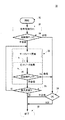
図3は、復号器112によって使用される通常のLDPC復号方法300の流れ図である。LDPC復号器112は、N個のLch値を受け取り、復号された情報語を出力する。復号方法300の心臓部は、確率伝搬と呼ばれる反復的2相メッセージパッシング・アルゴリズムである。確率伝搬は、タナー・グラフと呼ばれる視覚化の使用を用いて最もよく説明される。
LDPC Decoding: Probability Propagation FIG. 3 is a flow diagram of a conventional
図2(B)は、H行列200のタナー・グラフである。一般に、タナー・グラフは、1)H内の列の数と等しい(したがって、可変ビットの個数と等しい)ビットノードの個数n、2)H内の行の個数と等しい(したがって、パリティ・ビットの個数と等しい)チェックノードの個数m、3)それぞれが単一のビットノードを単一のチェックノードに接続する、辺としても知られる線、4)ビットノードnのそれぞれについて、受信器から受け取られたオリジナルのLch値、および5)ビットノードnのそれぞれについて、計算された硬判定出力値
![]()
![]()
![]()
![]()
タナー・グラフの辺は、(すなわち、可変)ビットノードnとチェックノードmの間の関係を表す、すなわち、辺は、H内の1を表す。たとえば、図2(B)では、辺202は、第1のビットノードn0を第4のチェックノードm3に接続し、これは、図2(A)のH行列200の第1列第4行に1があることを意味する。
The edges of the Tanner graph represent the relationship between the (ie variable) bit node n and the check node m, ie, the edge represents 1 in H. For example, in FIG. 2B, the
タナー・グラフは、二部グラフである、すなわち、辺は、ビットノードをチェックノードに接続することだけができ、ビットノードを別のビットノードにまたはチェックノードを別のチェックノードに接続することはできない。辺によって特定のチェックノードmに接続されたすべてのビットノードnの集合を、N(m)と表す。辺によって特定のビットノードnに接続されたすべてのチェックノードmの集合を、M(n)と表す。 A Tanner graph is a bipartite graph, that is, an edge can only connect a bit node to a check node and not connect a bit node to another bit node or a check node to another check node. Can not. A set of all bit nodes n connected to a specific check node m by an edge is denoted as N (m). A set of all check nodes m connected to a specific bit node n by an edge is represented as M (n).
特定の(ビットまたはチェック)ノードのインデックスは、グラフ内のそのノードのオリジナル・シーケンスである。(ビットまたはチェック)ノードの次数は、そのノードに接続された辺の個数である。したがって、タナー・グラフ内のビットノードnの次数は、対応するH行列内の列nの重みwcと等しく、タナー・グラフ内のチェックノードmの次数は、対応するH行列内の行mの重みwrと等しい。 The index of a particular (bit or check) node is the original sequence of that node in the graph. The order of a (bit or check) node is the number of sides connected to that node. Therefore, the order of bit node n in the Tanner graph is equal to the weight w c of column n in the corresponding H matrix, and the order of check node m in the Tanner graph is the row m in the corresponding H matrix. Equal to weight w r .
図3に戻って、処理は、ステップ302で開始され、ステップ304すなわち復号器初期化に進む。復号器初期化304は、ビットノードnに接続されたすべての辺(たとえば、図2(B)の202)にビットノードnに関連する対応するLch値をセットし、ビットノードnの
![]()
![]()
![]()
![]()
次に、ステップ304は、症候群チェック・ステップ306に、N個の
![]()
![]()
![]()
![]()
![]()
![]()
![]()
![]()
![]()
![]()
![]()
![]()
その代わりに、zが0ベクトルではない場合には、ベクトル
![]()
![]()
![]()
![]()
![]()
![]()
ベクトル
![]()
![]()
確率伝搬チェックノード更新ステップ310では、各チェックノードmは、集合N(m)内のすべてのビットノードnから受け取ったQnm個のメッセージを使用して、次の式2、3、および4に従って、Rmnと表されるメッセージを計算する。
次に、確率伝搬ビットノード更新ステップ312では、各ビットノードnは、次の式5に従ってQnm個のメッセージを計算する。
![]()
![]()
また、ビットノード更新ステップ312中に、各ビットノードnは、次の式6および7に従って、その
![]()
![]()
![]()
![]()
![]()
![]()
ビットノード更新ステップ312は、復号器の現在の
![]()
![]()
![]()
![]()
![]()
![]()
![]()
![]()
LDPC復号:巡回冗長検査および誤って満足されたチェックノード
症候群チェック306または314に合格することは、ベクトル
![]()
![]()
![]()
![]()
![]()
![]()
![]()
![]()
ベクトル
![]()
![]()
![]()
![]()
![]()
![]()
![]()
![]()
![]()
![]()
ステップ314に戻って、ベクトル
![]()
![]()
![]()
![]()
![]()
![]()
![]()
![]()
図3では、ステップ316が、反復の最大回数に達したかどうかを判定する。そうでない場合には、もう1つの復号反復308が実行される。その代わりに、反復の最大回数に達した場合には、復号器プロセス300が失敗した、すなわち、復号器は、「失敗した復号器」である。その場合には、プロセス300は、グローバル変数DCCWに偽をセットし、ベクトル
![]()
![]()
失敗した復号器のベクトル
![]()
![]()
![]()
![]()
![]()
![]()
![]()
![]()
失敗した復号プロセスを処理する2つの通常の方法は、1)対応するデータの再送を要求することまたは2)1つもしくは複数の後処理(PP)方法にベクトル
![]()
![]()
![]()
![]()
BER、SNR、およびエラーフロア
LDPC復号器のビット誤り率(BER)は、処理されるx個のビットについて何個の誤って復号されたビットが生成されるかを表す比率である。したがって、たとえば、10−9のBERを有する復号器は、平均して、処理される10億ビットごとに1つの誤ったビットを生成する。BERが小さいほど、復号器はよりよい。LDPC復号器のBERは、復号器が失敗するすなわち、復号された正しい符号語DCCWに収束せずに終了する時に、高まる(悪化する)。
BER, SNR, and Error Floor The bit error rate (BER) of an LDPC decoder is a ratio that represents how many erroneously decoded bits are generated for the x bits processed. Thus, for example, a decoder with a BER of 10-9 , on average, generates one erroneous bit for every billion bits processed. The smaller the BER, the better the decoder. The BER of an LDPC decoder increases (deteriorates) when the decoder fails, i.e., exits without converging on the correct decoded codeword DCCW.
LDPC復号器のBERは、復号器の入力信号の信号対雑音比(SNR)によって強く影響される。SNRの関数としてのBERのグラフは、通常、2つの別個の領域すなわち、BERがSNRの単位上昇を前提としてすばやく改善される(減少する)最初の「滝」領域と、SNRの単位上昇がBERのささやかな改善だけをもたらす後続の「エラーフロア」領域とを含む。したがって、エラーフロア領域での大きいBER改善を達成するためには、SNR向上以外の方法が必要である。 The BER of an LDPC decoder is strongly influenced by the signal to noise ratio (SNR) of the decoder input signal. A graph of BER as a function of SNR usually has two distinct regions: the first “waterfall” region where BER is quickly improved (decreased) assuming SNR unit increase, and the SNR unit increase is BER. And a subsequent “error floor” area that provides only modest improvement. Therefore, in order to achieve a large BER improvement in the error floor region, a method other than the SNR improvement is necessary.
LDPC復号のエラーフロア特性を改善する1つの方法は、符号語長さを増やすことである。しかし、符号語長さの増加は、LDPC復号に必要なメモリおよび他のコンピューティング・リソースをも増やす。したがって、HDドライブ上の読取りチャネル・デバイスについて通常そうであるように、そのようなリソースが厳密に制限される場合には、必要なエラーフロア改善をもたらすために、他の方法を見つけなければならない。 One way to improve the error floor characteristics of LDPC decoding is to increase the codeword length. However, increasing the codeword length also increases the memory and other computing resources required for LDPC decoding. Thus, if such resources are strictly limited, as is usually the case for read channel devices on HD drives, other methods must be found to provide the necessary error floor improvement. .
もう1つの不足するリソースが、処理サイクルである。通常、指定されたスループットを達成するために、HDドライブは、符号語を復号するために固定された個数の読取りチャネル処理サイクルを計上する。その予算を超える方法(すなわち、オフザフライ(off−the−fly)法)は、スループットを下げる。より望ましいのは、クロックサイクル割当内でDCCWを回復し、したがってスループットを下げないオンザフライ法である。 Another shortage of resources is the processing cycle. Usually, to achieve a specified throughput, an HD drive accounts for a fixed number of read channel processing cycles to decode a codeword. Methods that exceed that budget (ie, off-the-fly methods) reduce throughput. More desirable is an on-the-fly method that recovers DCCW within the clock cycle allocation and thus does not reduce throughput.
トラッピング・セットおよび支配的トラッピング・セット
(a,b)トラッピング・セットは、復号器が反復の最大回数以内に満足できないb個のUSCおよびこれらのUSCに関連するa個の誤りのあるビットノード(EBN)の集合である。トラッピング・セットの大多数は、5つ未満のUSCおよび10個未満のEBNを含む。トラッピング・セットは、LDPC復号器のエラーフロア特性に大きい影響を有する、すなわち、LDPC復号器がDCCWへの収束に失敗する時に、これは、しばしば、トラッピング・セットのゆえである。
Trapping Set and Dominant Trapping Set (a, b) A trapping set is a set of b USCs that the decoder cannot satisfy within the maximum number of iterations and a erroneous bit nodes associated with these USCs ( EBN). The majority of trapping sets include less than 5 USCs and less than 10 EBNs. The trapping set has a significant impact on the error floor characteristics of the LDPC decoder, ie when the LDPC decoder fails to converge to DCCW, this is often due to the trapping set.
LDPC復号器のエラーフロア特性を改善する1つの形は、(i)失敗した復号器の
![]()
![]()
異なるトラッピング・セットは、破壊された時に、エラーフロア特性の異なる改善をもたらす。支配的トラッピング・セット(DTS)は、その破壊がBER/エラーフロア特性の指定された改善をもたらす、トラッピング・セットの最小限のセットを指す。たとえば、DTS−1は、BERの単一桁の、たとえば10−9から10−10への大きさ改善をもたらすトラッピング・セットの最小限のセットを指し、DTS−3は、BERの3桁の、たとえば10−10から10−13への大きさ改善をもたらす。 Different trapping sets result in different improvements in error floor characteristics when destroyed. The dominant trapping set (DTS) refers to a minimal set of trapping sets whose destruction results in a specified improvement in BER / error floor characteristics. For example, DTS-1 refers to a minimal set of trapping sets that provide a single digit BER improvement in size, eg, 10 −9 to 10 −10 , and DTS-3 is a 3 digit BER. For example, a size improvement from 10 −10 to 10 −13 is brought about.
ニア・コードワードのリスト復号
リスト復号は、トラッピング・セットを検出し、破壊する、1つの後処理法である。リスト復号では、ベクトル
![]()
![]()
トラッピング・セット・シミュレーション
リスト復号に必要なトラッピング・セット・リストは、通常、ソフトウェア・シミュレーション・ツールおよびハードウェア・シミュレーション・ツールを使用してオフラインで生成される。図4は、トラッピング・セットを識別し、これらのトラッピング・セットに関するさまざまな情報を記録するオフライン・トラッピング・セット(TS)シミュレーション・ツール400のブロック図である。ツール400は、たとえば、フィールドプログラマブル・ゲート・アレイ(FPGA)内で実施することができる。LDPCの正しい符号語(CCW)402が、チャネルおよび信号モデル404に送られ、このチャネルおよび信号モデル404は、図1の雑音のある通信路114の挙動をエミュレートする。チャネルおよび信号モデル404は、Lch値406をLDPC復号器408に出力する。LDPC復号器408が、ニア・コードワード(NCW)410を生成する場合には、NCW 410が、症候群チェック・モジュール412および不一致位置レコーダ414に送られる。症候群チェック412は、NCW 410内のすべてのUSCのインデックス416を出力する。不一致位置レコーダ414は、NCW 410をCCW 402と比較し、NCW 410内のすべてのEBNのインデックス418を出力する。USCインデックス416およびEBNインデックス418が、トラッピング・セット(TS)情報420を構成する。
Trapping Set Simulation The trapping set list required for list decoding is usually generated offline using software simulation tools and hardware simulation tools. FIG. 4 is a block diagram of an offline trapping set (TS) simulation tool 400 that identifies trapping sets and records various information regarding these trapping sets. Tool 400 may be implemented, for example, in a field programmable gate array (FPGA). The LDPC correct codeword (CCW) 402 is sent to the channel and
所与のLDPC実施態様について、すべての可能なトラッピング・セットが、数百万個に達する場合がある。しかし、その実施態様のエラーフロアにおける大きい(すなわち、1桁以上の)改善の達成は、通常、すべての可能なトラッピング・セットのサブセットすなわち支配的トラッピング・セット(DTS)のみを必要とする。したがって、オフラインTSシミュレーション・ツール400は、DTS−Nコンパイラ422を含み、DTS−Nコンパイラ422は、その入力としてTS情報420をとり、DTS−N情報424を生成する。
For a given LDPC implementation, all possible trapping sets may reach millions. However, achieving large (ie, one or more orders of magnitude) improvement in the error floor of that embodiment typically requires only a subset of all possible trapping sets, ie the dominant trapping set (DTS). Therefore, the offline TS simulation tool 400 includes a DTS-
DTS−Nコンパイラ422は、3ステップ・プロセスすなわち、収集、ランキング、および評価を使用する。トラッピング・セット収集法は、トラッピング・セットを検出するのに、符号グラフの構造に基づく決定論的雑音インパルスを利用する。次に、収集されたトラッピング・セットは、ディスタンス・トゥー・エラー・バウンダリ(distance−to−error boundary、DEB)値によってランキングされ、ここで、小さいDEB値を有するトラッピング・セットが、エラーフロアにより多く寄与する。次に、重点的サンプリングが、トラッピング・セットを評価し、予測されたランキングを確認するのに使用される。
The DTS-
実際には、そのようなFPGAベースのオフライン・シミュレーションは、実行に1年を要する可能性がある。たとえば、4Gb/s HDドライブについて10−15のBERをもたらすトラッピング・セットを識別するためには、オフライン・シミュレーション・ツール(たとえば、図4のツール400)を約289日間動作させる必要がある。通常、この時間制約は問題ではない。というのは、しばしば、HDドライブ読取りチャネルの最終設計とチップの量産との間に1年から2年の遅延があるからである。 In practice, such an FPGA-based off-line simulation can take a year to run. For example, to identify a trapping set resulting in BER of 10 -15 for 4Gb / s HD drive, off-line simulation tool (e.g., tool 400 of FIG. 4) must be operated for about 289 days. Usually this time constraint is not a problem. This is often because there is a one to two year delay between the final design of the HD drive read channel and the mass production of the chip.
トラッピング・セット読取り専用メモリ(TS−ROM)
したがって、図4のツール400のようなオフラインTSシミュレーション・ツールを使用することによって、特定のLDPC実施態様についてエラーフロア特性の改善をもたらす1つまたは複数のトラッピング・セットまたは支配的トラッピング・セットを先験的に識別することが可能である。ランタイム環境でリスト復号を実施する1つの形は、オフライン生成された図4のトラッピング・セット情報420をトラッピング・セット読取り専用メモリ(TS−ROM)に格納し、そのTS−ROMをリスト・デコーダ・プログラムと結合することである。TS−ROMリスト・デコーダ・プログラムは、
![]()
Thus, by using an offline TS simulation tool, such as tool 400 of FIG. 4, one or more trapping sets or dominant trapping sets that lead to improved error floor characteristics for a particular LDPC implementation are preceded. It is possible to identify experimentally. One form of performing list decoding in a runtime environment is to store the trap set information 420 of FIG. 4 generated off-line in a trap set read only memory (TS-ROM) and store the TS-ROM in a list decoder. It is to combine with the program. TS-ROM list decoder program is
![]()
通常、TS−ROM情報は、単一リンク・リストまたは二重リンク・リストにランダムに格納され、このリストは、ブルート・フォース順次検索を使用して検索される。通常、各(a,b)トラッピング・セットは、TS−ROMリスト内で(2+a+b)個のレコードを占める。したがって、(4,4)トラッピング・セット・プロファイル(すなわち、4つのUSCおよび4つのEBN)について、10個のレコードすなわち、4つのUSCがあることを示す1つのレコード、それに続く4つの個々のUSCレコード、次に4つのEBNがあることを示すレコード、それに続く4つの個々のEBNレコードがある。通常のTS−ROMリスト実施態様は、約100個のトラッピング・セットを格納し、誤って満足されたチェックノードに関する情報は全く格納しない。 Typically, TS-ROM information is randomly stored in a single linked list or a double linked list, which is searched using a brute force sequential search. Normally, each (a, b ) trapping set occupies (2 + a + b) records in the TS-ROM list. Thus, for a (4,4) trapping set profile (ie, 4 USCs and 4 EBNs), there are 10 records, one record indicating that there are 4 USCs, followed by 4 individual USCs. There is a record, followed by a record indicating that there are four EBNs, followed by four individual EBN records. A typical TS-ROM list implementation stores about 100 trapping sets and does not store any information about erroneously satisfied check nodes.
そのようなTS−ROM実施態様が経済的に実用的であるためには、単一のTS−ROMが、多数の実施態様で、要求されるエラーフロア改善を達成できなければならない。しかし、トラッピング・セットは、同一のLDPC符号が実施される時であっても、実施態様によって変化する。たとえば、2つのHDドライブで使用されるLDPC符号が同一の場合であっても、これらのHDドライブに関連するトラッピング・セットが異なる場合がある。具体的に言うと、研究から、トラッピング・セットが、HDドライブのジッタ・プロファイル、記号間干渉特性、およびパルス整形方式によって影響を受けることが示された。これらの要因は、異なる製造業者のHDドライブの間だけではなく、同一製造業者の異なるHDドライブ・モデルの間でも変化する可能性があり、同一モデルの異なるプロダクション・ランの間の変動すらある。したがって、トラッピング・セットは、2つの同一モデルのハード・ドライブの間でさえ変化し得る。そのように多数の異なるHDドライブのLDPCトラッピング・セットをシミュレートすることは、非実用的である。それでも、HDドライブの大きいクラスに共通するトラッピング・セットだけをロードされたTS−ROMは、特定のHDドライブと対にされた時に、要求されるレベルのエラーフロア改善をもたらさない可能性がある。 In order for such a TS-ROM implementation to be economically practical, a single TS-ROM must be able to achieve the required error floor improvement in multiple implementations. However, the trapping set varies from implementation to implementation, even when the same LDPC code is implemented. For example, even if the LDPC codes used in two HD drives are the same, the trapping sets associated with these HD drives may be different. Specifically, studies have shown that trapping sets are affected by HD drive jitter profiles, intersymbol interference characteristics, and pulse shaping schemes. These factors can change not only between different manufacturers' HD drives, but also between different HD drive models of the same manufacturer, and even between different production runs of the same model. Thus, the trapping set can even change between two identical model hard drives. It is impractical to simulate such a large number of different HD drive LDPC trapping sets. Nevertheless, a TS-ROM loaded with only a trapping set common to a large class of HD drives may not provide the required level of error floor improvement when paired with a particular HD drive.
TS−ROMの性能を改善する1つの方法は、製造されたデバイスのテスト・モデルから得られた結果を用いて、FPGAベースのオフライン・シミュレーション・ツール(たとえば、図4のツール400)によって生成された情報を補足することである。通常、回路設計が最終化された後に、その設計の限られた個数のテスト・モデルが、量産が始まる前に製造され、テストのために配布される。特定のHDドライブ実施態様について10−15のBERをもたらすトラッピング・セットを判定するのに1年を要する場合があるが、10−12のBERをもたらすトラッピング・セットを判定するのには、1日のみを要する。したがって、テスト・モデルは、限られた時間期間の間にLDPCテスト・モードで動作させられ、発見されたトラッピング・セットのすべてが格納される。まだTS−ROM内にはない、発見されたトラッピング・セットのすべてが、TS−ROMに追加される。消費者に配布される実際のデバイスを使用することによって、この方法は、FPGAベースのオフライン・シミュレーション・ツール(たとえば、図4のツール400)に発見されなかった可能性があるトラッピング・セットを取り込む。 One way to improve the performance of a TS-ROM is generated by an FPGA-based offline simulation tool (eg, tool 400 of FIG. 4) using results obtained from a manufactured device test model. To supplement the information. Typically, after a circuit design is finalized, a limited number of test models for that design are manufactured and distributed for testing before mass production begins. Although it may take a year to determine the trapping set providing 10 -15 BER for a particular HD drive embodiments, to determine the trapping set resulting in BER of 10 -12, 1 day Requires only. Thus, the test model is run in LDPC test mode for a limited time period and all of the discovered trapping sets are stored. All of the discovered trapping sets that are not yet in TS-ROM are added to TS-ROM. By using the actual device distributed to the consumer, the method captures a trapping set that may not have been found in an FPGA-based offline simulation tool (eg, tool 400 of FIG. 4). .
トラッピング・セット・ランダムアクセス・メモリ(TS−RAM)
TS−ROMの静的トラッピング・セット・リストに対する1つのランタイム代替案は、トラッピング・セット情報をトラッピング・セット・ランダムアクセス・メモリ(TS−RAM)に格納し、図4のオフライン・トラッピング・セット・シミュレーション・ツール400を、実際の個々のデバイス(たとえば、HDドライブ)に対して動作するランタイム・トラッピング・セット収集分析ツールにすることである。チャネルおよび信号モデル(たとえば、図4のモデル404)から初期値を受け取るのではなく、ランタイム・ツールは、その特定のデバイスの実際の信号を処理する。ランタイム・ツールは、リスト復号器機能性を含む、すなわち、ランタイム・ツールは、観察されたUSCをTS−RAM内の格納されたトラッピング・セット情報と照合し、一致が見つかる場合には、格納された情報を使用して、復号器ビットノード値を変更し、復号器を再始動することを試みる。一致が見つからない場合には、ランタイム・ツールは、観察されたトラッピング・セットを分析する、すなわち、USCに関連するEBNを識別し、観察されたトラッピング・セットが、TS−RAMへの格納に関するしきい要件(たとえば、DTS−Nへのメンバシップ)を満足したかどうかを判定する。
Trapping set random access memory (TS-RAM)
One runtime alternative to the TS-ROM static trap set list is to store the trap set information in a trap set random access memory (TS-RAM) and the offline trap set set of FIG. The simulation tool 400 is to be a runtime trapping set collection and analysis tool that operates on actual individual devices (eg, HD drives). Rather than receiving initial values from the channel and signal model (eg,
理論的に、上で説明したTS−RAMツールは、すべての実施態様のトラッピング・セット・プロファイルに適合することができる。現実には、図4のオフライン・シミュレーション・ツール400によって実行されるトラッピング・セット/支配的トラッピング・セット・シミュレーションは、計算的に複雑である。具体的に言うと、おそらくは数百万個のトラッピング・セットから支配的トラッピング・セットを構成することが、特に複雑である。この複雑さが、上で説明したTS−RAMツールをほとんどのHDドライブに不適切にする。通常、HDドライブは、高いレート(たとえば、4ギガビット毎秒)でデータを出力し、非常に低いBER/エラーフロア・レート(たとえば、10−13から10−15)を要求するが、そのファームウェアでささやかなコンピューティング・リソースのみを提供する。 Theoretically, the TS-RAM tool described above can be adapted to the trapping set profile of all embodiments. In reality, the trapping set / dominant trapping set simulation performed by the offline simulation tool 400 of FIG. 4 is computationally complex. Specifically, constructing a dominant trapping set, perhaps from millions of trapping sets, is particularly complex. This complexity makes the TS-RAM tool described above unsuitable for most HD drives. Typically, an HD drive outputs data at a high rate (eg, 4 gigabits per second) and requires a very low BER / error floor rate (eg, 10 −13 to 10 −15 ), but the firmware is modest. Only useful computing resources.
さらに、TS−RAMツールは、図4のオフライン・シミュレーション・ツール400に似て、EBNインデックスを生成するために正しい符号語(CCW)を必要とする。CCWは、オフライン・シミュレーション環境では簡単に入手可能であるが、ランタイム環境ではそうではない。 Furthermore, the TS-RAM tool, like the offline simulation tool 400 of FIG. 4, requires the correct codeword (CCW) to generate the EBN index. CCW is readily available in an offline simulation environment, but not in a runtime environment.
本発明のある種の実施形態によれば、ROM内の格納されたトラッピング・セット・プロファイルの編成のために、方法が実行される。トラッピング・セット・プロファイルは、優位性によってすなわち、LDPC復号器のエラーフロア特性に対する影響によって、ランキングされる。より支配的なトラッピング・セット・プロファイルは、満足されないチェックノード(USC)と誤って満足されたチェックノード(MSC)との両方に関する情報を含むが、より支配的でないトラッピング・セット・プロファイルは、USCに関する情報だけを含む。次に、トラッピング・セット・プロファイル情報は、複数のリンクされた階層データ・テーブルに編成され、この階層データ・テーブルは、ポインタチェース検索を使用する最も支配的な一致するトラッピング・セット・プロファイルのすばやい突止めおよび取出しを可能にする。 According to certain embodiments of the invention, a method is performed for the organization of stored trapping set profiles in ROM. Trapping set profiles are ranked by dominance, that is, by their impact on the error floor characteristics of the LDPC decoder. A more dominant trapping set profile contains information about both unsatisfied check nodes (USCs) and falsely satisfied check nodes (MSCs), but a less dominant trapping set profile is USC Only information about The trapping set profile information is then organized into multiple linked hierarchical data tables, which are the quickest of the most dominant matching trapping set profiles using pointer chase searches. Allows for location and removal.
本発明のある種の実施形態によれば、RAM内の支配的トラッピング・セットの収集および識別のために、効率的なランタイム方法が実行される。可能な場合には、新たに発見されたトラッピング・セットが、RAMに格納され、次に、トラッピング・セットが最後に一致した時以降にRAMが検索された回数、トラッピング・セットがRAMに追加された時以降にそのトラッピング・セットが一致した総回数、満足されないチェックノードの個数、および誤りのあるビットノードの個数という要因のうちのいずれか1つまたは複数に基づいてソートされ、またはランキングされる。低いランキングのトラッピング・セット・プロファイルは、新たに発見されたトラッピング・セット・プロファイルのための余地を作るためにRAMから削除される。したがって、図4のDTS−Nコンパイラ422で使用されるものなどの支配的トラッピング・セットの先験的識別のための非常に計算的に複雑なオフライン方法を使用することに加えてまたはその代わりに、本発明のこれらの実施形態は、できる限り多数の新たに発見されたトラッピング・セットが格納され、非支配的トラッピング・セット・プロファイルが周期的なランキングおよび削除によって選別される、低い計算的複雑さの後天的方法を実行する。
In accordance with certain embodiments of the present invention, an efficient runtime method is performed for collecting and identifying the dominant trapping set in RAM. If possible, the newly discovered trapping set is stored in RAM, and then the trapping set is added to RAM for the number of times the RAM has been searched since the last time the trapping set was matched. Sorted or ranked based on one or more of the following factors: the total number of times that the trapping set has matched, the number of unsatisfied check nodes, and the number of erroneous bit nodes . The lower ranking trap set profile is deleted from RAM to make room for the newly discovered trap set profile. Thus, in addition to or instead of using a very computationally complex off-line method for a priori identification of the dominant trapping set such as that used in the DTS-
本発明の実施形態は、通常は、オンザフライ方法である、すなわち、LDPC復号のために計上されたクロックサイクル内にDCCWを回復でき、したがって、システム・スループットに悪影響を与えない。 Embodiments of the present invention are typically on-the-fly methods, i.e., can recover the DCCW within the clock cycles accounted for for LDPC decoding and thus do not adversely affect system throughput.
図5は、本発明の一実施形態によるLDPC復号システム500のブロック図である。図1の従来技術のHDドライブ100に類似する本発明のHDドライブでは、図5のLDPC復号システム500は、図1のLDPC復号器112に類似するLDPC復号器の一部として実施される。その範囲で、図5の入力Lch値は、図1の復号器入力Lch値に類似し、図5の出力
LDPC復号器502は、Lch値を受け取り、図3のLDPC復号プロセス300を実行し、ベクトル
![]()
![]()
データ・テーブル
実行中に、特定のPP方法が、PP方法実行可能プログラム・コードとは別々のデータ構造にアクセスすることを必要とする場合がある。具体的に言うと、TS−ROMリスト復号方法およびTS−RAMリスト復号方法は、それぞれTS−ROM 510およびTS−RAM 520に格納されたトラッピング・セット情報の1つまたは複数のリストにアクセスする。
Data Table During execution, a particular PP method may require access to a data structure that is separate from the PP method executable program code. Specifically, the TS-ROM list decoding method and the TS-RAM list decoding method access one or more lists of trapping set information stored in TS-
図5の例示的実施形態では、TS−ROM 510は、4つのテーブルすなわち、Bテーブル512、Pテーブル514、Eテーブル516、およびEIテーブル518を含む。TS−RAM 520は、2つのテーブルすなわち、RAM Pテーブル522およびRAMインデックス524を含む。テーブルは、1つまたは複数の等しいサイズの行(レコード)および1つまたは複数の等しいサイズの列(フィールド)に編成された、ディジタル・データの2次元行列である。テーブルのレコードは、0から始めて上から下へ順番に番号を付けられる。この番号が、レコード番号である。
In the exemplary embodiment of FIG. 5, TS-
Pテーブル514および522は、USCおよびそれに関連するEBNに関する情報を含む。Bテーブル512は、ROM Pテーブル514のポインタ情報を含む。EIテーブル518は、MSCに関する情報を含み、Eテーブル516は、EIテーブル518のポインタ情報を含む。RAMインデックス・テーブル524は、RAM Pテーブル522のポインタ情報を含む。 P tables 514 and 522 contain information about the USC and its associated EBN. The B table 512 includes pointer information of the ROM P table 514. The EI table 518 includes information regarding the MSC, and the E table 516 includes pointer information of the EI table 518. The RAM index table 524 includes pointer information of the RAM P table 522.
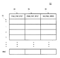
図6は、図5のROM Pテーブル514の例示的レイアウトである。ROM Pテーブル514は、トラッピング・セット・プロファイル情報すなわち、USCインデックスおよびEBNインデックスを含む。ROM Pテーブル514は、各格納されたトラッピング・セットのUSCごとに1つの、複数のレコード(行)を含む。レコード番号602は、0から始まる、Pテーブル514内のレコードの順序位置である。
FIG. 6 is an exemplary layout of the ROM P table 514 of FIG. ROM P table 514 includes trapping set profile information, ie, USC index and EBN index. The ROM P table 514 includes a plurality of records (rows), one for each USC of each stored trapping set. The
ROM Pテーブル514内の各レコードは、3つのフィールドすなわち、LAYER 604、USC_INDEX 606、およびEBN_INDEX 608を含む。一部のLDPC復号器は、更新動作のセットを並列に実行するように構成され、これを、レイヤと称する。LAYER 604は、USCを含んだ復号レイヤの番号を示す。USC_INDEX 606は、USCのインデックスを含む。EBN_INDEX 608は、USCに関連する1つまたは2つのEBNのインデックスを含む。
Each record in ROM P table 514 includes three fields:
ROM Pテーブル514は、まずb(すなわち、
![]()
![]()
各b範囲内では、トラッピング・セットは、優位性すなわち、そのトラッピング・セットがエラーフロア特性に対して有する影響によってソートされる。エラーフロア特性に対してより大きい影響を有するトラッピング・セットは、b範囲の始めに現れ、より少ない影響を有するトラッピング・セットは、終り近くに現れる。その後、特定のトラッピング・セットのレコードは、USC_INDEX 606によってソートされる。 Within each b range, the trapping sets are sorted by dominance, ie the effect that the trapping set has on the error floor characteristics. Trapping sets with greater impact on error floor characteristics appear at the beginning of the b range, and trapping sets with less impact appear near the end. The records for a particular trapping set are then sorted by USC_INDEX 606.
図7は、図5のBテーブル512の例示的レイアウトである。Bテーブル512は、ROM Pテーブル514内のb値ごとに、ROM Pテーブル514内およびEテーブル516内のそのb値の最初の出現へのポインタと、そのb値のEテーブル516内のレコードの個数とを含む。したがって、Bテーブル512内には、b値ごとに単一のレコードがあり、このb値は、レコード番号702によって示される。しかし、レコード番号702は0から始まるが、b値は、通常は、2以上から始まる。したがって、本発明のこの例示的実施形態では、レコード番号702にオフセットを加算して、対応するb値を作る。たとえば、b≧2を有するトラッピング・セットだけが格納される場合には、2のオフセットが、対応するb値に達するために各レコード番号に加算される。
FIG. 7 is an exemplary layout of the B table 512 of FIG. For each b value in the ROM P table 514, the B table 512 has a pointer to the first occurrence of that b value in the ROM P table 514 and the E table 516, and the record of that b value in the E table 516. Including the number. Therefore, there is a single record for each b value in the B table 512, and this b value is indicated by a
フィールドPTABLE_START_OFFSET 704は、ROM Pテーブル514内の特定のb値の最初の出現の位置を含む。フィールドETABLE_START_OFFSET 706は、Eテーブル516内の特定のb値の最初の出現の位置を含む。フィールドNUM_ETABLE_ENTRIES 708は、この特定のb値の、Eテーブル516内のレコードの個数を含む。
図8は、図5のEテーブル516の例示的レイアウトである。Eテーブル516は、EIテーブル518内のMSCレコードへのポインタを含む。Eテーブル516内の各レコードは、レコード番号802、EITABLE_START_ADDRESSフィールド804、およびEITABLE_END_ADDRESSフィールド806を有する。EITABLE_START_ADDRESSフィールド804は、EIテーブル518内の対応するデータの最初の出現へのポインタを含み、EITABLE_END_ADDRESSフィールド806は、EIテーブル518内の対応するデータの最後の出現へのポインタを含む。
FIG. 8 is an exemplary layout of the E table 516 of FIG. E table 516 includes a pointer to the MSC record in EI table 518. Each record in the E table 516 has a
図9は、図5のEIテーブル518の例示的レイアウトである。EIテーブル518は、MSCに関連するEBNのインデックスを格納する。EIテーブル518内の各レコードは、レコード番号902を有し、2つのフィールドすなわちBLOCK_COLUMNフィールド904およびB_INDEXフィールド906を含む。BLOCK_COLUMNフィールド904は、EBNが配置されたブロック列を示し、B_INDEXフィールド906は、EBNのインデックスである。
FIG. 9 is an exemplary layout of the EI table 518 of FIG. The EI table 518 stores an EBN index associated with the MSC. Each record in the EI table 518 has a
図10は、図5のRAM Pテーブル522の例示的レイアウトである。RAM Pテーブル522は、ROM Pテーブル514内では見つからない新たに識別されたトラッピング・セットのプロファイルを格納する。RAM Pテーブル522内の各行(すなわち、レコード)は、レコード番号1002を有し、2つのフィールドすなわち2ビットのTAGフィールド1004およびR_WORDフィールド1006を含む。TAGフィールド1004の4つの可能な値は、R_WORDフィールド1006内のレコード・タイプおよびデータの構造を示す。TAGフィールド1004が11の値を有する場合には、レコードは、トラッピング・セット全体に関する情報を含むプライマリ・レコードである。TAGフィールド1004が10の値を有する場合には、レコードは、セカンダリ・レコードであり、トラッピング・セット・プロファイル内の特定のUSCに関する情報を含む。TAGフィールド1004が00または01の値を有する場合には、R_WORDフィールド1006は空である、すなわち、このレコードは、新たに識別されたトラッピング・セットのプロファイル情報を格納するのに使用可能である。トラッピング・セット・プロファイルは、通常、単一のプライマリ・レコードとそれに続くb個のセカンダリ・レコードとを含む。
FIG. 10 is an exemplary layout of the RAM P table 522 of FIG. The RAM P table 522 stores profiles of newly identified trapping sets that are not found in the ROM P table 514. Each row (ie, record) in the RAM P table 522 has a
レコードがプライマリ・レコードである場合には、R_WORDフィールド1006は、4つのサブフィールドすなわち、(i)b値サブフィールド1008、(ii)トラッピング・セットEBNの個数を記録するa値サブフィールド1010、(iii)このトラッピング・セットに最後に一致したTS−RAM検索の個数を示すLAST_HIT_NUMサブフィールド1012、および(iv)このトラッピング・セットがTS−RAMに格納された時以降にこの特定のトラッピング・セット・プロファイルが観察されたトラッピング・セットと一致した回数を記録するHIT_COUNTERサブフィールド1014を含む。
If the record is a primary record, the
レコードがセカンダリ・レコードである場合には、R_WORDフィールド1006は、トラッピング・セット内の単一のUSCのレイヤ(LAYERフィールド1016)およびインデックス(USC_INDEXフィールド1018)と、そのUSCに関連する1つまたは複数のEBNのインデックス(EBN_INDEXフィールド1020)とを含む。
If the record is a secondary record, the
図11は、図5のRAMインデックス・テーブル524の例示的レイアウトである。RAMインデックス・テーブル524内には、RAM Pテーブル522内のトラッピング・セット・プロファイルごとに1つのレコードがある。RAMインデックス・テーブル524内の各レコードは、単一のフィールドRAM_PTABLE_OFFSET 1102を含む。RAM_PTABLE_OFFSET 1102は、RAM Pテーブル522内の特定のトラッピング・セット・プロファイルの始めへのポインタである、すなわち、RAM_PTABLE_OFFSET 1102は、トラッピング・セット・プロファイル・プライマリ・レコードの図10のレコード番号1002を含む。RAMインデックス・テーブル524内のレコードは、優位性によってソートされ、その結果、RAMインデックス・テーブル524内の最初のレコードは、RAM Pテーブル522内の最も支配的なトラッピング・セットをポイントし、RAMインデックス・テーブル524内の最後のレコードは、RAM Pテーブル522内の最も支配的でないレコードをポイントするようになる。
FIG. 11 is an exemplary layout of the RAM index table 524 of FIG. There is one record in the RAM index table 524 for each trapping set profile in the RAM P table 522. Each record in the RAM index table 524 includes a
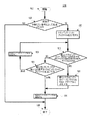
図12は、図5のLDPC復号システム500によって使用される例示的プロセス1200の流れ図である。処理は、ステップ1202で開始され、ステップ1204すなわち、図5のLDPC復号器502によるLch値のLDPC復号に進む。ステップ1204でのLDPC復号がDCCWを作る場合には、プロセス1200は、ステップ1218で終了する。そうでない場合には、処理は、ステップ1206すなわち、TS−ROMリスト復号(図5のポストプロセッサ504によって実行される)に進む。
FIG. 12 is a flowchart of an
ステップ1206がDCCWを作る場合には、プロセス1200は、ステップ1218で終了する。そうでない場合には、処理は、ステップ1208すなわち、TS−RAMリスト復号(図5のポストプロセッサ504によって実行される)に進む。ステップ1208がDCCWを作る場合には、プロセス1200は、ステップ1218で終了する。そうでない場合には、処理は、1つまたは複数の追加の後処理方法1210、1212、…、1214(図5のポストプロセッサ504によって実行される)に進み、これらは、類似する形で動作する。
If
TS−RAMリスト復号1208または追加の後処理方法1210、1212、…、1214のいずれかがDCCWを作る場合には、処理はステップ1216に進み、ここで、図5のTS−RAM 520が、おそらくはTS−RAMアップデータ506によって更新される。その後、処理はステップ1218で終了する。
If either TS-
図12は、後処理方法1207〜1214の1つの可能なシーケンシングを示す。後処理方法のほとんどすべてのシーケンスを使用することができるが、いくつかのシーケンスは、他のシーケンスより実用的である。たとえば、ROMに既に格納されているトラッピング・セットがRAM内で重複しないことを保証するために、TS−ROMリスト復号をTS−RAMリスト復号の前にシーケンシングすることが望ましい。 FIG. 12 shows one possible sequencing of post-processing methods 1207-1214. Although almost any sequence of post-processing methods can be used, some sequences are more practical than others. For example, it may be desirable to sequence TS-ROM list decoding prior to TS-RAM list decoding to ensure that trapping sets already stored in ROM do not overlap in RAM.
TS−ROMリスト復号
図13は、図5のポストプロセッサ504によって実施される図12の例示的なTS−ROMリスト復号プロセス1206の流れ図である。処理は、ステップ1302で開始され、ステップ1304に進み、ここで、プロセス1206は、図12のLDPC復号器1204から受け取られたベクトル
![]()
![]()
![]()
![]()
![]()
![]()
ステップ1306では、復号器の現在の状態を格納し、状態1というラベルを付ける。次に、処理はステップ1308に継続され、ここで、観察されたUSCを、まず復号レイヤによって、次にインデックスによってソートする。次に、ステップ1310で、次の4つの値を図5のBテーブル512からフェッチし、格納する。
(1)b=bobservedについて、図7のPTABLE_START_OFFSETフィールド704、
(2)b=bobserved+1について、図7のPTABLE_START_OFFSETフィールド704、
(3)b=bobservedについて、図7のETABLE_START_OFFSETフィールド706、および
(4)b=bobservedについて、図7のNUM_ETABLE_ENTRIESフィールド708。
第1の値は、プロセス1206に、図5のPテーブル514内のどこで一致するトラッピング・セット情報の検索を開始すべきか(すなわち、USCインデックスおよびEBNインデックス)を指示し、第2の値は、プロセス1206に、いつその検索を終了すべきかを指示する。同様に、第3および第4の値は、プロセス1206に、拡張情報(すなわち、MSCインデックス)の検索を開始すべき場所および終了すべき場所を指示する。
In step 1306, the current state of the decoder is stored and labeled as
(1) b = about b observed,
(2) For b = b observed + 1, the
(3) b = about b observed,
The first value instructs
したがって、たとえば、bobserved=5の場合には、プロセス1206は、b=5およびb=6について図7のPTABLE_START_OFFSETフィールド704の値をフェッチし、b=5について図7のETABLE_START_OFFSETフィールド706の値および図7のNUM_ETABLE_ENTRIESフィールド708の値をフェッチする。
Thus, for example, if b observed = 5, the
次に、ステップ1312で、プロセス1206は、図5のPテーブル514を選択し、b=bobservedのPTABLE_START_OFFSETの格納された値によって示されるアドレスに行く。次に、ステップ1314で、TS−ROMから、観察されたUSCと一致するトラッピング・セットを検索する。
Next, in
図14は、図13の例示的なTS−ROM検索プロセス1314の流れ図である。プロセス1314は、ステップ1402で開始され、ステップ1404で、観察されたUSCの同形一致である図5のPテーブル514内の次のレコードを検索する。観察されたUSCの特定のセットの同形一致は、USCの個数およびこれらのUSCの間の距離が観察されたUSCと同一であるトラッピング・セットである。したがって、観察されたUSCが[1,3,10]である場合には、[1,3,10]は一致であり、[2,4,11]は同形一致であり、[3,5,12]、[4,6,13]なども同形一致である。一致が見つからない場合には、プロセス1314は、一致なしの状況1406で終了する。
FIG. 14 is a flowchart of the exemplary TS-
そうではなく、ステップ1404で一致が見つかる場合には、ステップ1408で、一致するPテーブル・レコードの図6のEBN_INDEXフィールド608の値を格納する。EBN_INDEXフィールドは、この一致するトラッピング・セットに関連する1つおよびおそらくは2つの誤りのあるビットノードのインデックスを格納する。
Otherwise, if a match is found at
次に、プロセス1314は、すべての拡張情報すなわち、この一致するトラッピング・セット内の誤って満足されたチェックノード(MSC)に関連するEBNのインデックスを突き止めることを試みる。拡張情報は、EIテーブル518内で保持される。しかし、拡張情報は、Pテーブル514内に格納されたすべてのトラッピング・セットについて保持されるのではなく、各b範囲内のトラッピング・セットのサブセットについてのみ保持される。そのサブセットは、特定のb範囲内のより支配的なトラッピング・セットすなわち、エラーフロア特性に対するより大きい影響を有するトラッピング・セットに対応する。上で述べたように、Pテーブル514内では、特定のb範囲内のトラッピング・セットが、優位性によってソートされ、したがって、拡張情報は、そのb範囲内の最初のx個のレコードのみについて保持される。EIテーブル518内の各b範囲の始めおよび終りは、Bテーブル512内のフィールド、ETABLE_START_OFFSET 706およびNUM_ETABLE_ENTRIES 708によって示される。
Next, the
プロセス1314は、ROM Pテーブル514のレコードから検索する時に、トラッピング・セットの内部カウントを維持する。したがって、たとえば、プロセス1314が、図6のPテーブル514内のb=2トラッピング・セットから検索している場合に、プロセス1314は、レコード0および1をトラッピング・セット0(たとえば、図6のトラッピング・セット610)として、レコード2および3をトラッピング・セット1(たとえば、図6のトラッピング・セット612)としてなど、識別する。このトラッピング・セット番号を、TSNUMと称する。
ステップ1410で、TSNUMを、図13のステップ1310で格納されたNUM_ETABLE_ENTRIESフィールドの値と比較する。TSNUMがNUM_ETABLE_ENTRIESの値より大きい場合には、拡張情報は使用可能ではなく、プロセス1314は、一致、拡張情報なしの状況1412で終了する。
In step 1410, TSNUM is compared with the value of the NUM_ETABLE_ENTRIES field stored in step 1310 of FIG. If TSNUM is greater than the value of NUM_ETABLE_ENTRIES, extended information is not available and
そうではなく、ステップ1410で、TSNUMがNUM_ETABLE_ENTRIESの格納された値以下であることがわかる場合には、拡張情報が、この一致するトラッピング・セットについて存在する。ステップ1414で、TSNUMをETABLE_START_OFFSETの格納された値に加算して、変数ETABLE_ENTRY_ADDRESSを作る。
Otherwise, at step 1410, if it is found that TSNUM is less than or equal to the stored value of NUM_ETABLE_ENTRIES, extended information is present for this matching trapping set. In
次に、ステップ1416で、プロセス1314は、図5のEテーブル516を選択し、変数ETABLE_ENTRY_ADDRESSの値と等しいアドレスを有するレコードに行き、図8のEITABLE_START_ADDRESSフィールド804および図8のEITABLE_END_ADDRESSフィールド806の値を格納する。
Next, at
次に、ステップ1418で、プロセス1314は、図5のEIテーブル518を選択し、格納されたEITABLE_START_ADDRESS値とEITABLE_END_ADDRESS値との間のすべてのレコードの、図9のBLOCK_COLUMNフィールド904および図9のB_INDEXフィールド906の値を格納する。最後に、プロセス1314は、一致、拡張情報ありの状況1420で終了する。
Next, in
図13に戻って、ステップ1314が、一致なしの状況で終了する場合には、プロセス1206は、ステップ1316で終了する。
Returning to FIG. 13, if
ステップ1314が、一致、拡張情報なしの状況で終了する場合には、プロセス1206は、このトラッピング・セットに関連するUSCインデックスおよびいくつかのEBNインデックスを、拡張情報なしで(すなわち、MSCに関連するEBNのインデックスなしで)処理する。この場合に、ステップ1318で、これらのEBNインデックスのビットノードを反転し、ステップ1320で、反復LDPC復号を実行する。ステップ1320の処理は、復号器初期化ステップ304および初期症候群チェック・ステップ306がスキップされることを除いて、図3のプロセス300と同一である。ステップ1320がDCCWに収束する場合には、プロセス1206は、ステップ1316で終了する。そうでない場合には、ステップ1322で、復号器を状態1に復元し、次の一致するトラッピング・セットを、ステップ1314で検索する。
If
ステップ1314が、一致、拡張情報ありの状況で終了する場合には、プロセス1206は、一致するトラッピング・セットに関連するすべてのEBNのインデックスを有する。この場合には、確率伝搬(たとえば、図3のステップ310および312)を実行する必要はない。そうではなく、ステップ1324で、EBNを反転し、結果のベクトル
![]()
![]()
![]()
![]()
![]()
![]()
![]()
![]()
![]()
![]()
![]()
![]()
![]()
![]()
![]()
![]()
TS−RAMリスト復号
図5のポストプロセッサ504によって利用されるもう1つのPP方法が、図12のTS−RAMリスト復号1208すなわち、ランダムアクセス・メモリなどの揮発性メモリに格納されたトラッピング・セット情報を使用するトラッピング・セットのリスト復号である。TS−RAMリスト復号は、図5のRAM Pテーブル522が選択されたトラッピング・セットのUSCおよびEBNの情報を格納するという点で、TS−ROMリスト復号に似ている。しかし、ROM Pテーブル514とは異なって、RAM Pテーブル522は、図5のTS−RAMアップデータ506によってランタイム中に変更される。したがって、最も重要な情報だけ、たとえばUSCインデックスおよびEBNインデックスだけが、格納される。拡張情報(たとえば、図5のEIテーブル518)は、TS−RAM内では維持されない。
TS-RAM List Decoding Another PP method utilized by the
プロファイルも、RAM Pテーブル522内にはどのような形であれソートされない。そうではなく、図5の別々のRAMインデックス・テーブル524は、優位性によってソートされた、RAM Pテーブル522内に格納されたトラッピング・セット・プロファイルのアドレスのリストを維持する。 Profiles are also not sorted in RAM P table 522 in any way. Rather, the separate RAM index table 524 of FIG. 5 maintains a list of trapping set profile addresses stored in the RAM P table 522, sorted by dominance.
図15は、図12の例示的なTS−RAMリスト復号プロセス1208の流れ図である。処理は、ステップ1502で開始され、ステップ1504に進み、このステップ1504は、目的および動作において図13のステップ1304と同一である。ステップ1504が偽に評価される場合には、プロセス1208は、ステップ1506で終了し、そうでない場合には、処理は、ステップ1508に継続され、ここで、現在の復号器状態を記録し、状態1というラベルを付ける。その後、処理はステップ1510に継続される。
FIG. 15 is a flow diagram of the exemplary TS-RAM
ステップ1510では、プロセス1208は、図5のRAM Pテーブル522内の最も支配的なトラッピング・セット・プロファイルに行く。具体的に言うと、RAMインデックス・テーブル524は、優位性によってRAM Pテーブル522内のプロファイルをランキングするので、プロセス1208は、RAMインデックス・テーブル524内の最初のレコードに行き、図11のRAM_PTABLE_OFFSETフィールド1102の値を取り出す。次に、プロセス1208は、RAM Pテーブル522内のポインタをその格納されたオフセット値に移動する。
In
ステップ1512で、プロセス1208は、TS−RAM検索が実行された総数すなわち、プロセス1208が実行された総回数を記憶するグローバル変数RAM_SEARCH_COUNTを増分する。また、ステップ1512で、プロセス1208は、観察されたUSCの同形一致について、RAMインデックス・テーブル524によって示される順序すなわち減少する優位性の順で、RAM Pテーブル522内のプロファイルを調べる。一致が見つからない場合には、処理はステップ1514に継続される。
At
そうではなく、ステップ1512で一致が見つかる場合には、ステップ1516で、一致したプロファイルの図10のLAST_HIT_NUMフィールド1012に、グローバル変数RAM_SEARCH_COUNTの値をセットし、図10のHIT_COUNTERフィールド1014を1つ増分する。次に、ステップ1518で、図10のEBN_INDEXフィールド1020の値を格納する。ステップ1520で、EBN_INDEX値に配置されたビットノードを反転し、ステップ1522で、LDPC復号を実行する。ステップ1522は、図13のステップ1320と同一である。復号プロセス1522がDCCWに収束する場合には、処理はステップ1514に継続され、そうでない場合には、ステップ1524で、復号器を状態1にリセットし、その後、処理は、ステップ1512に継続され、ここで、別の同形一致をPテーブル522内で検索する。
Otherwise, if a match is found in
ステップ1514では、プロセス1208は、図11のRAMインデックス・テーブル524を更新する。具体的に言うと、ステップ1514で、RAM Pテーブル522内のフィールド、たとえばLAST_HIT_NUM 1012、HIT_COUNTERフィールド1014、USCノードの個数フィールド1008、およびEBNの個数フィールド1010の任意の組合せに基づいて、RAM Pテーブル522内のすべてのTS−RAMプロファイルをソートする。次に、すべてのソートされたプロファイルのアドレスすなわちすべてのプライマリ・レコードのレコード番号1002を、図11のRAMインデックス・テーブル524内にレコードとして格納する。プロファイル・アドレスは、それらがステップ1514でソートされたのと同一の順序(たとえば、最も支配的から最も少なく支配的へ)でRAMインデックス・テーブル524に格納される。
ステップ1514が完了した後に、処理は、ステップ1506で終了する。
In step 1514, the
After step 1514 is complete, the process ends at step 1506.
TS−RAMアップデータ
図12のプロセス1200の議論で説明したように、TS−ROMリスト復号1206以外の任意の後処理方法がDCCWに達する場合に、それが、新しいトラッピング・セットが発見されたことを意味する場合がある。そうである場合には、ステップ1216が、その新しいトラッピング・セットを図5のRAM Pテーブル522に追加することを試みる場合がある。
TS-RAM Updater As described in the discussion of
一実施形態では、ステップ1216は、支配的トラッピング・セットをTS−RAM 520内で保持するための、低い複雑さのプロセスである。具体的に言うと、この実施形態では、ステップ1216は、図4のDTS−Nコンパイラ422によって実行される計算などの支配的トラッピング・セットを先験的に判定するための網羅的計算を実行するのではなく、その代わりに、(i)1つまたは複数の要因、たとえば、トラッピング・セットが最後に一致した時以降にTS−RAMが何回検索されたか、トラッピング・セットが一致した総回数、USCの個数、EBNの個数などの任意の組合せに基づいてTS−RAMトラッピング・セットをランキングし、次に、(ii)新たに発見されたトラッピング・セットのための余地を作るために、最も低いランキングのトラッピング・セットを追い出す。これらの要因を使用するTS−RAM 520内のトラッピング・セットのランキングは、通常、オフライン・シミュレーション・ツール(たとえば、図4のコンパイラ422)によって実行される分析よりかなりより少なく複雑である。
In one embodiment,
図16は、図12の例示的なTS−RAM更新プロセス1216の流れ図である。処理は、ステップ1602で開始され、ステップ1604に進み、ここで、DCCWが図12のTS−RAMリスト復号プロセス1208によって生成されたかどうかを判定する。そうである場合には、トラッピング・セット・プロファイルをTS−RAMに追加する必要はなく、プロセス1216は、ステップ1608で終了する。
FIG. 16 is a flowchart of the exemplary TS-
そうではなく、ステップ1604がno/偽に評価される場合には、これは、TS−ROMリスト復号またはTS−RAMリスト復号以外のある後処理方法がDCCWに達し、したがって、新しいトラッピング・セットが発見され、RAMに付加されなければならないことを意味する。ステップ1610で、トラッピング・セット・プロファイルを生成する。トラッピング・セット・プロファイルは、トラッピング・セットUSBのインデックスと、これらのUSBに関連するEBNのインデックスとを含む。USBインデックスは、図5のLDPC復号器502によって既に生成済みである。EBNインデックスを生成するために、ステップ1610で、ポストプロセッサ504によって生成されたDCCW
![]()
![]()
ステップ1612で、新しいトラッピング・セット・プロファイルを付加するのに十分な空き空間があるかどうかを判定する。そうである場合には、ステップ1614で、新しいトラッピング・セット・プロファイルを、RAM Pテーブル522に付加し、プロセス1216は、ステップ1616に進む。
At
しかし、ステップ1612で、新しいトラッピング・セット・プロファイルを付加するのに十分な空き空間がRAM Pテーブル522内にない場合には、ステップ1618で、最も低いランキングの追出しに適するトラッピング・セット・プロファイルを追い出す。この例では、プロファイルの追出し適格性は、そのプロファイルが最後に一致した時以降にRAMが検索された回数すなわち、グローバル変数RAM_SEARCH_COUNTの値からプロファイルのLAST_HIT_NUMフィールドの値を引いたものによって決定される。介在する検索の回数が、指定されたしきい値より多い場合には、そのプロファイルは、追出しに適する。すべてのプロファイルが、まず追出し適格性によってランキングされると仮定すると、すべての追出しに適するレコードは、図11のRAMインデックス・テーブル524の終りにある。
However, if at
したがって、ステップ1618では、RAMインデックス・テーブル524内の最後のレコードを選択し、RAM_PTABLE_OFFSETフィールド1102の値を取り出す。RAM Pテーブル522内で格納されたオフセット値(取り出されたRAM_PTABLE_OFFSET値によって示される)に配置されたプロファイルが、追出しに適する場合には、RAM Pテーブル522内の格納されたオフセット値に配置されたプライマリ・レコードおよび関連するセカンダリ・レコードが削除される。ステップ1620で、RAMインデックス・テーブルMSBを更新し、その後、制御はステップ1612にループ・バックし、ここで、新しいトラッピング・セット・プロファイルを付加するのに十分な空き空間がRAM Pテーブル522内にあるかどうかを判定する。ステップ1620の処理は、図15のステップ1514の処理と同一である。
Accordingly, in
そうではなく、ステップ1618で、最低ランキングのプロファイルが追出しに適さない場合には、処理は、ステップ1616に継続される。ステップ1616では、RAMインデックス・テーブル524を更新し、処理は、ステップ1608で終了する。ステップ1616の処理は、図15のステップ1514の処理と同一である。
Otherwise, if the lowest ranking profile is not suitable for eviction at
本発明を、LDPCコーディングおよび復号を実施するハード・ディスク・ドライブの文脈で説明したが、本発明は、それに限定はされない。一般に、本発明を、LDPCコーディングおよび復号を用いる任意の適切な通信経路内で実施することができる。 Although the present invention has been described in the context of a hard disk drive that implements LDPC coding and decoding, the present invention is not so limited. In general, the present invention can be implemented in any suitable communication path using LDPC coding and decoding.
さらに、上で使用された例示的な確率伝搬アルゴリズムは、オフセットmin−sumアルゴリズム(OMS)であるが、本発明は、それに限定はされず、本発明を、任意の確率伝搬変形、たとえば、sum−productアルゴリズム(SPA)またはBahl−Cocke−Jelinek−Raviv(BCJR)アルゴリズムと共に使用することができる。 Furthermore, although the exemplary belief propagation algorithm used above is an offset min-sum algorithm (OMS), the present invention is not so limited and the present invention can be applied to any probability propagation variant, eg, sum. Can be used with the product algorithm (SPA) or the Bahl-Cocke-Jelinek-Raviv (BCJR) algorithm.
さらに、上で使用された確率伝搬の例は、すべてのチェックノードが単一のチェックノード更新ステップ中に更新され、その後、すべてのビットノードが単一のビットノード更新ステップで更新される、特定の復号スケジュール(フラッディング・スケジュール)を使用したが、本発明は、それには限定されず、本発明を、任意の復号スケジュール、たとえば、ローシリアルスケジュール、カラムシリアルスケジュール、およびローカラム・シリアルスケジュールと共に使用することができる。 Furthermore, the example of probability propagation used above is that all check nodes are updated during a single check node update step, and then all bit nodes are updated in a single bit node update step. Although a decoding schedule (flooding schedule) is used, the present invention is not so limited, and the present invention is used with any decoding schedule, for example, a row serial schedule, a column serial schedule, and a row column serial schedule. be able to.
さらに、上で使用された例示的LDPC復号器は、非階層復号器であったが、本発明は、それに限定はされず、本発明を、階層復号器と非階層復号器との両方と共に使用することができる。 Further, although the exemplary LDPC decoder used above was a non-hierarchical decoder, the present invention is not so limited and the present invention is used with both hierarchical and non-hierarchical decoders. can do.
さらに、上で与えた例示的TS−RAM実施態様は、トラッピング・セット・プロファイルをHDドライブの読取りチャネル内のRAMに格納すると仮定したが、本発明は、それに限定はされない。RAM Pテーブル(たとえば、図5の522)を、HDドライブのプラッタに格納するか、フラッシュ・メモリなどの別々のメモリ内に格納することもできる。 Further, although the exemplary TS-RAM implementation given above assumed that the trapping set profile is stored in RAM within the read channel of the HD drive, the present invention is not so limited. The RAM P table (eg, 522 in FIG. 5) can be stored on the platter of the HD drive or in a separate memory such as a flash memory.
さらに、上で与えた例示的TS−ROM実施態様は、読取り専用メモリの文脈で説明されたが、本発明は、それに限定はされない。一般に、本明細書と特許請求の範囲との両方で使用される時に、用語「ROM」は、そのデバイス内のデータを変更できるか否かにかかわりなく、静的TSプロファイル・データを格納するすべてのデータストレージ・デバイスを指すと解釈されなければならない。 Furthermore, although the exemplary TS-ROM implementation given above has been described in the context of read-only memory, the present invention is not so limited. In general, as used in both this specification and the claims, the term “ROM” refers to anything that stores static TS profile data, regardless of whether the data in the device can be changed or not. Should be construed to refer to any data storage device.
さらに、本発明の実施形態を、LDPC符号の文脈で説明したが、本発明は、それに限定はされない。本発明の実施形態を、グラフによって定義できる任意の符号、たとえば、トルネード符号、構造化IRA符号のために実施することができる。というのは、これが、トラッピング・セットに苦しむグラフ定義される符号であるからである。 Furthermore, although embodiments of the present invention have been described in the context of LDPC codes, the present invention is not so limited. Embodiments of the present invention can be implemented for any code that can be defined by a graph, such as a tornado code, a structured IRA code. This is because this is a graph-defined code that suffers from trapping sets.
本発明を、対数尤度比の受取りに関して説明したが、本発明は、それに限定はされない。尤度比などの他のソフト値または硬判定値が処理される、本発明の実施形態を想定することができる。 Although the present invention has been described with respect to receiving log-likelihood ratios, the present invention is not limited thereto. Embodiments of the present invention can be envisaged where other soft values such as likelihood ratios or hard decision values are processed.
本発明を、方法およびこれらの方法を実践する装置の形で実施することができる。本発明を、磁気記録媒体、光記録媒体、ソリッド・ステート・メモリ、フロッピ・ディスケット、CD−ROM、ハード・ドライブ、または任意の他の機械可読記憶媒体などの有形の媒体内で実施されるプログラム・コードの形で実施することもでき、プログラム・コードがコンピュータなどの機械にロードされ、その機械によって実行される時に、その機械は、本発明を実践する装置になる。本発明を、記憶媒体に格納される、機械にロードされ、かつ/またはこれによって実行される、あるいは電気配線またはケーブリングを介する、光ファイバを介する、もしくは電磁放射を介するなどのある伝送媒体または搬送波を介して伝送されるいずれであれ、プログラム・コードの形で実施することもでき、プログラム・コードがコンピュータなどの機械にロードされ、その機械によって実行される時に、その機械は、本発明を実践する装置になる。汎用プロセッサ上で実施される時に、プログラム・コード・セグメントは、プロセッサと組み合わさって、特定の論理回路に類似して動作する独自のデバイスをもたらす。 The present invention can be implemented in the form of methods and apparatus for practicing these methods. Program implemented in tangible medium such as magnetic recording medium, optical recording medium, solid state memory, floppy diskette, CD-ROM, hard drive, or any other machine readable storage medium It can also be implemented in the form of code, which becomes a device for practicing the invention when the program code is loaded into and executed by a machine such as a computer. The invention may be stored in a storage medium, loaded into a machine and / or performed by it, or via electrical wiring or cabling, via optical fiber, or via electromagnetic radiation, or Anything transmitted over a carrier wave can be implemented in the form of program code, which when loaded into and executed by a machine, such as a computer, the machine Become a device to practice. When implemented on a general-purpose processor, the program code segments combine with the processor to provide a unique device that operates analogously to specific logic circuits.
そうではないと明示的に述べられない限り、各数値および範囲は、単語「約」(“about”or“approximately”)が値または範囲の値に先行するかのように近似として解釈されなければならない。 Unless explicitly stated otherwise, each numerical value and range must be interpreted as an approximation as if the word “about” or “approximately” preceded the value of the value or range. Don't be.
さらに、添付の特許請求の範囲に表された本発明の範囲から逸脱せずに、本発明の性質を説明するために説明され、図示された部分の詳細、材料、および配置におけるさまざまな変更を当業者が行えることを理解されたい。 Furthermore, various changes in the details, materials, and arrangements of the parts described and illustrated to illustrate the nature of the present invention without departing from the scope of the invention as set forth in the appended claims. It should be understood that one skilled in the art can do this.
特許請求の範囲での図面番号および/または図面符号の使用は、特許請求の範囲の解釈を容易にするために請求される主題の1つまたは複数の可能な実施形態を識別することを意図されたものである。そのような使用を、これらの特許請求の範囲の範囲を対応する図面に示された実施形態に必ず限定するものとして解釈してはならない。 The use of drawing numbers and / or drawing symbols in the claims is intended to identify one or more possible embodiments of the claimed subject matter in order to facilitate the interpretation of the claims. It is a thing. Such use should not be construed as necessarily limiting the scope of these claims to the embodiments shown in the corresponding drawings.
本明細書に示された例示的方法のステップが、必ずしも説明された順序で実行されることを必要とせず、そのような方法のステップの順序が、単に例示と理解されなければならないことを理解されたい。同様に、本発明のさまざまな実施形態と一貫する方法において、追加ステップをそのような方法に含めることができ、ある種のステップを削除しまたは組み合わせることができる。 It is understood that the steps of the exemplary methods presented herein do not necessarily have to be performed in the order described, and the order of the steps of such methods should only be understood as examples. I want to be. Similarly, in steps consistent with various embodiments of the invention, additional steps can be included in such methods, and certain steps can be deleted or combined.
次の方法請求項の要素は、存在する場合に、対応するラベル付けを伴って特定のシーケンスで詳説されるが、請求項詳説が、これらの要素の一部またはすべてを実施するための特定のシーケンスを他の形で暗示しない限り、これらの要素は、必ずしもその特定のシーケンスで実施されることに限定はされないことが意図されている。 Next Method Claim elements, if present, are detailed in a specific sequence with corresponding labeling, but the claim details are specific for implementing some or all of these elements. Unless the sequence is otherwise implied, it is intended that these elements are not necessarily limited to being performed in that particular sequence.
本明細書での「一実施形態」(“one embodiment”or“an embodiment”)への言及は、その実施形態に関連して説明される特定の特徴、構造、または特性を、本発明の少なくとも1つの実施形態に含めることができることを意味する。本明細書のさまざまな場所での句「一実施形態で」の出現は、必ずしもすべてが同一の実施形態に言及するものではなく、必ずしも他の実施形態と相互に排他的な別々のまたは代替の実施形態でもない。同一のことが、用語「実施態様」にもあてはまる。 References herein to “one embodiment” or “an embodiment” refer to a particular feature, structure, or characteristic described in connection with that embodiment, at least It means that it can be included in one embodiment. The appearances of the phrase “in one embodiment” in various places in the specification are not necessarily all referring to the same embodiment, and are not necessarily separate or alternative to each other. It is not an embodiment. The same applies to the term “embodiment”.
Claims (10)
(a)候補の復号された符号語を生成するために、前記符号化されたデータを復号することと、
(b)前記候補の復号された符号語が復号された正しい符号語ではない場合に、前記復号された正しい符号語を生成することを試みるためにトラッピング・セット(TS)−ROMリスト復号方法を実行することであって、
前記候補の復号された符号語は、少なくとも1つの満足されないチェックノードを有し、満足されないチェックノードは、パリティ検査に合格しないチェックノードであり、
前記TS−ROMリスト復号方法は、ROMメモリ内に格納された1つまたは複数のTSプロファイルにアクセスし、
第1の格納されたTSプロファイルは、少なくとも1つの満足されないチェック(USC)ノードの格納された情報および少なくとも1つの誤って満足されたチェック(MSC)ノードの格納された情報を含み、MSCノードは、(i)誤りのあるビットノード(EBN)に関連し、(ii)前記パリティ検査を満足するチェックノードであり、
第2の格納されたTSプロファイルは、1つまたは複数のUSCノードおよび1つまたは複数のMSCノードを有するトラッピング・セットに関連し、前記第2の格納されたTSプロファイルは、前記1つまたは複数のUSCノードの格納された情報を含むが、前記1つまたは複数のMSCノードに関する情報を含まない
実行することと
を含む方法。 A method for decoding encoded data encoded using a graph-based code, comprising:
(A) decoding the encoded data to generate candidate decoded codewords;
(B) A trapping set (TS) -ROM list decoding method to attempt to generate the decoded correct codeword if the candidate decoded codeword is not the correct decoded codeword. To execute,
The candidate decoded codeword has at least one unsatisfied check node, and the unsatisfied check node is a check node that does not pass a parity check;
The TS-ROM list decoding method accesses one or more TS profiles stored in a ROM memory,
The first stored TS profile includes stored information of at least one unsatisfied check (USC) node and stored information of at least one incorrectly satisfied check (MSC) node, where the MSC node is (Ii) a check node associated with an erroneous bit node (EBN) and (ii) satisfying the parity check;
The second stored TS profile is associated with a trapping set having one or more USC nodes and one or more MSC nodes, and the second stored TS profile is the one or more Including stored information of USC nodes of the first, but not including information about the one or more MSC nodes.
(b1)前記候補の復号された符号語内の前記少なくとも1つのUSCノードに関連する1つまたは複数のEBNを識別することと、
(b2)(i)前記候補の復号された符号語が1つまたは複数のMSCノードを有し、(ii)前記ROMメモリが前記1つまたは複数のMSCノードに関する情報を含む場合に、前記1つまたは複数のMSCに関連する1つまたは複数のEBNを識別することと、
(b3)前記識別されたEBNを変更することと、
(b4)さらなる処理を実行することであって、
ステップ(b2)が1つまたは複数のEBNを識別する場合に、前記さらなる処理は、前記変更された候補の復号された符号語に対して症候群チェックを実行することを含み、
ステップ(b2)が1つまたは複数のEBNを識別しない場合に、前記さらなる処理は、変更された符号化されたデータを復号することを含む
実行することと
を含む、請求項1に記載の発明。 The TS-ROM list decoding method includes:
(B1) identifying one or more EBNs associated with the at least one USC node in the candidate decoded codeword;
(B2) (i) if the candidate decoded codeword has one or more MSC nodes, and (ii) the ROM memory contains information about the one or more MSC nodes Identifying one or more EBNs associated with one or more MSCs;
(B3) changing the identified EBN;
(B4) performing further processing,
If step (b2) identifies one or more EBNs, the further processing includes performing a syndrome check on the modified candidate decoded codeword;
The invention of claim 1, wherein if the step (b2) does not identify one or more EBNs, the further processing includes decoding the modified encoded data. .
前記満足されないチェックノードが配置される復号レイヤ(たとえば、LAYER)と、
前記復号レイヤ内の前記満足されないチェックノード(USC)のインデックス(たとえば、USC_INDEX)と、
前記満足されないチェックノードに関連する1つまたは複数の誤りのあるビットノード(EBN)の1つまたは複数のインデックス(たとえば、EBN_INDEX)と
を含み、TSプロファイル内の誤って満足されたチェックノードごとに、前記TSプロファイルは、
前記誤って満足されたチェックノードに関連する1つまたは複数の誤りのあるビットノードの位置情報(たとえば、BLOCK_COLUMN、B_INDEX)
を含む、請求項1に記載の発明。 For each unsatisfied check node in the TS profile, the TS profile is
A decoding layer (eg, LAYER) where the unsatisfied check node is located;
An index (eg, USC_INDEX) of the unsatisfied check node (USC) in the decoding layer;
One or more indexes (eg, EBN_INDEX) of one or more erroneous bit nodes (EBN) associated with the unsatisfied check node, and for each erroneously satisfied check node in the TS profile The TS profile is
Location information of one or more erroneous bit nodes associated with the erroneously satisfied check node (eg, BLOCK_COLUMN, B_INDEX)
The invention of claim 1 comprising:
前記複数の格納されたTSプロファイルの前記復号レイヤ、USCインデックス、およびEBNインデックスは、第1テーブル(たとえば、Pテーブル514)に格納され、
誤って満足されたチェックノードに関連する前記誤りのあるビットノードの前記位置情報は、第2テーブル(たとえば、EIテーブル518)に格納される
請求項4に記載の発明。 The ROM memory includes a plurality of stored TS profiles;
The decoding layer, USC index, and EBN index of the plurality of stored TS profiles are stored in a first table (eg, P table 514);
5. The invention of claim 4, wherein the location information of the erroneous bit node associated with an erroneously satisfied check node is stored in a second table (eg, EI table 518).
同一の個数の満足されないチェックノードを有する格納されたTSプロファイルの各グループ内の前記格納されたTSプロファイルは、TSプロファイル優位性によって順序付けられ、TSプロファイルの優位性は、前記関連するトラッピング・セットがステップ(a)の前記復号のエラーフロア特性に対して有する影響に依存する
請求項5に記載の発明。 The stored TS profiles are grouped in the first table based on the number of unsatisfied check nodes in the stored TS profile,
The stored TS profiles within each group of stored TS profiles having the same number of unsatisfied check nodes are ordered by TS profile dominance, which is determined by the associated trapping set. The invention according to claim 5, which depends on the influence of step (a) on the error floor characteristics of the decoding.
前記満足されないチェックノードは、前記TSプロファイル内で復号レイヤによってグループ化され、
同一の復号レイヤを有する満足されないチェックノードのグループ内の前記満足されないチェックノードは、USCインデックスによって配置される
請求項6に記載の発明。 For each TS profile with multiple unsatisfied check nodes,
The unsatisfied check nodes are grouped by a decoding layer in the TS profile;
The invention of claim 6, wherein the unsatisfied check nodes in a group of unsatisfied check nodes having the same decoding layer are arranged by a USC index.
前記第3テーブルは、一致するTSプロファイルの誤って満足されたチェックノードに関連する前記誤りのあるビットノードの前記位置情報の前記第2テーブル内のアドレス(たとえば、EITABLE_START_ADDRESS、EITABLE_END_ADDRESS)を識別し、
前記第1テーブル内と同一の個数の満足されないチェックノードを有する格納されたTSプロファイルのグループごとに、前記第4テーブルは、
(i)格納されたTSプロファイルの前記グループの前記第1テーブル内の開始アドレス(たとえば、PTABLE_START_OFFSET)と、
(ii)誤って満足されたチェックノードに関連する位置情報を有する前記グループ内のTSプロファイルの個数(たとえば、NUM_ETABLE_ENTRIES)と、
(iii)格納されたTSプロファイルの前記グループの前記第3テーブル内の開始アドレス(たとえば、ETABLE_START_OFFSET)と
を識別する、請求項5に記載の発明。 The ROM memory further includes a third table (eg, E table 516) and a fourth table (eg, B table 512);
The third table identifies an address in the second table of the location information of the erroneous bit node associated with an erroneously satisfied check node of a matching TS profile (eg, EITABLE_START_ADDRESS, EITABLE_END_ADDRESS);
For each group of stored TS profiles having the same number of unsatisfied check nodes as in the first table, the fourth table is:
(I) a start address in the first table of the group of stored TS profiles (eg, PTABLE_START_OFFSET);
(Ii) the number of TS profiles in the group that have location information associated with erroneously satisfied check nodes (eg, NUM_ETABLE_ENTRIES);
6. The invention of claim 5, wherein: (iii) identifies a starting address (eg, ETABLE_START_OFFSET) in the third table of the group of stored TS profiles.
(a)候補の復号された符号語を生成するために、前記符号化されたデータを復号する手段と、
(b)前記候補の復号された符号語が復号された正しい符号語ではない場合に、前記復号された正しい符号語を生成することを試みるためにトラッピング・セット(TS)−ROMリスト復号方法を実行する手段であって、
前記候補の復号された符号語は、少なくとも1つの満足されないチェックノードを有し、満足されないチェックノードは、パリティ検査に合格しないチェックノードであり、
前記TS−ROMリスト復号方法は、ROMメモリ内に格納された1つまたは複数のTSプロファイルにアクセスし、
第1の格納されたTSプロファイルは、少なくとも1つの満足されないチェック(USC)ノードの格納された情報および少なくとも1つの誤って満足されたチェック(MSC)ノードの格納された情報を含み、MSCノードは、(i)誤りのあるビットノード(EBN)に関連し、(ii)前記パリティ検査を満足するチェックノードであり、
第2の格納されたTSプロファイルは、1つまたは複数のUSCノードおよび1つまたは複数のMSCノードを有するトラッピング・セットに関連し、前記第2の格納されたTSプロファイルは、前記1つまたは複数のUSCノードの格納された情報を含むが、前記1つまたは複数のMSCノードに関する情報を含まないことを含む装置。 An apparatus for decoding encoded data encoded using a graph-based code, comprising:
(A) means for decoding the encoded data to generate candidate decoded codewords;
(B) A trapping set (TS) -ROM list decoding method to attempt to generate the decoded correct codeword if the candidate decoded codeword is not the correct decoded codeword. Means to perform,
The candidate decoded codeword has at least one unsatisfied check node, and the unsatisfied check node is a check node that does not pass a parity check;
The TS-ROM list decoding method accesses one or more TS profiles stored in a ROM memory,
The first stored TS profile includes stored information of at least one unsatisfied check (USC) node and stored information of at least one incorrectly satisfied check (MSC) node, where the MSC node is (Ii) a check node associated with an erroneous bit node (EBN) and (ii) satisfying the parity check;
The second stored TS profile is associated with a trapping set having one or more USC nodes and one or more MSC nodes, and the second stored TS profile is the one or more of including stored information USC node device that includes not contain information for the one or more MSC nodes.
Applications Claiming Priority (3)
| Application Number | Priority Date | Filing Date | Title |
|---|---|---|---|
| US8929708P | 2008-08-15 | 2008-08-15 | |
| US61/089,297 | 2008-08-15 | ||
| PCT/US2008/086537 WO2010019169A1 (en) | 2008-08-15 | 2008-12-12 | Rom list-decoding of near codewords |
Publications (3)
| Publication Number | Publication Date |
|---|---|
| JP2012500513A JP2012500513A (en) | 2012-01-05 |
| JP2012500513A5 JP2012500513A5 (en) | 2012-02-16 |
| JP5276173B2 true JP5276173B2 (en) | 2013-08-28 |
Family
ID=41669126
Family Applications (4)
| Application Number | Title | Priority Date | Filing Date |
|---|---|---|---|
| JP2011522962A Expired - Fee Related JP5363573B2 (en) | 2008-08-15 | 2008-12-12 | Near codeword RAM list decoding |
| JP2011522963A Expired - Fee Related JP5276173B2 (en) | 2008-08-15 | 2008-12-12 | ROM list decoding of near codeword |
| JP2011523008A Pending JP2012500514A (en) | 2008-08-15 | 2009-04-08 | Error correction decoder using multiple check node algorithms |
| JP2013231731A Ceased JP2014027704A (en) | 2008-08-15 | 2013-11-08 | Error-correction decoder employing multiple check-node algorithms |
Family Applications Before (1)
| Application Number | Title | Priority Date | Filing Date |
|---|---|---|---|
| JP2011522962A Expired - Fee Related JP5363573B2 (en) | 2008-08-15 | 2008-12-12 | Near codeword RAM list decoding |
Family Applications After (2)
| Application Number | Title | Priority Date | Filing Date |
|---|---|---|---|
| JP2011523008A Pending JP2012500514A (en) | 2008-08-15 | 2009-04-08 | Error correction decoder using multiple check node algorithms |
| JP2013231731A Ceased JP2014027704A (en) | 2008-08-15 | 2013-11-08 | Error-correction decoder employing multiple check-node algorithms |
Country Status (7)
| Country | Link |
|---|---|
| US (17) | US8464129B2 (en) |
| EP (3) | EP2223431A1 (en) |
| JP (4) | JP5363573B2 (en) |
| KR (3) | KR101418467B1 (en) |
| CN (3) | CN101803206B (en) |
| TW (3) | TWI435211B (en) |
| WO (3) | WO2010019169A1 (en) |
Families Citing this family (238)
| Publication number | Priority date | Publication date | Assignee | Title |
|---|---|---|---|---|
| US8281212B1 (en) | 2007-03-30 | 2012-10-02 | Link—A—Media Devices Corporation | Iterative ECC decoder with out of order completion |
| US7958427B1 (en) * | 2007-03-30 | 2011-06-07 | Link—A—Media Devices Corporation | ECC with out of order completion |
| US8359522B2 (en) | 2007-05-01 | 2013-01-22 | Texas A&M University System | Low density parity check decoder for regular LDPC codes |
| US8799742B1 (en) * | 2007-07-30 | 2014-08-05 | Marvell International Ltd. | QC-LDPC decoder with list-syndrome decoding |
| US8127209B1 (en) | 2007-07-30 | 2012-02-28 | Marvell International Ltd. | QC-LDPC decoder with list-syndrome decoding |
| US8219878B1 (en) * | 2007-12-03 | 2012-07-10 | Marvell International Ltd. | Post-processing decoder of LDPC codes for improved error floors |
| US8245104B2 (en) | 2008-05-02 | 2012-08-14 | Lsi Corporation | Systems and methods for queue based data detection and decoding |
| US8370711B2 (en) * | 2008-06-23 | 2013-02-05 | Ramot At Tel Aviv University Ltd. | Interruption criteria for block decoding |
| US20090319860A1 (en) * | 2008-06-23 | 2009-12-24 | Ramot At Tel Aviv University Ltd. | Overcoming ldpc trapping sets by decoder reset |
| US20100037121A1 (en) * | 2008-08-05 | 2010-02-11 | The Hong Kong University Of Science And Technology | Low power layered decoding for low density parity check decoders |
| JP5363573B2 (en) | 2008-08-15 | 2013-12-11 | エルエスアイ コーポレーション | Near codeword RAM list decoding |
| US8185796B2 (en) * | 2008-08-20 | 2012-05-22 | Nec Laboratories America, Inc. | Mitigation of fiber nonlinearities in multilevel coded-modulation schemes |
| US8291285B1 (en) | 2008-09-18 | 2012-10-16 | Marvell International Ltd. | Circulant processing scheduler for layered LDPC decoder |
| WO2010036209A1 (en) * | 2008-09-26 | 2010-04-01 | Agency For Science, Technology And Research | Decoding circuit and encoding circuit |
| US8321772B1 (en) * | 2008-10-20 | 2012-11-27 | Link—A—Media Devices Corporation | SOVA sharing during LDPC global iteration |
| US8219873B1 (en) * | 2008-10-20 | 2012-07-10 | Link—A—Media Devices Corporation | LDPC selective decoding scheduling using a cost function |
| US8161345B2 (en) | 2008-10-29 | 2012-04-17 | Agere Systems Inc. | LDPC decoders using fixed and adjustable permutators |
| TWI469533B (en) * | 2008-11-07 | 2015-01-11 | Realtek Semiconductor Corp | Decoder for parity-check code and receiving system |
| US9356623B2 (en) | 2008-11-26 | 2016-05-31 | Avago Technologies General Ip (Singapore) Pte. Ltd. | LDPC decoder variable node units having fewer adder stages |
| US8935601B1 (en) | 2008-12-03 | 2015-01-13 | Marvell International Ltd. | Post-processing methodologies in decoding LDPC codes |
| US8234556B2 (en) * | 2008-12-30 | 2012-07-31 | Intel Corporation | Broadcast receiver and method for optimizing a scale factor for a log-likelihood mapper |
| KR101539002B1 (en) * | 2009-01-02 | 2015-07-24 | 삼성전자주식회사 | Device and method for 1-bit error correction |
| US8347195B1 (en) | 2009-01-22 | 2013-01-01 | Marvell International Ltd. | Systems and methods for near-codeword detection and correction on the fly |
| CN101903890B (en) | 2009-03-05 | 2015-05-20 | Lsi公司 | Improved turbo-equalization methods for iterative decoders |
| EP2307960B1 (en) * | 2009-04-21 | 2018-01-10 | Avago Technologies General IP (Singapore) Pte. Ltd. | Error-floor mitigation of codes using write verification |
| US8578256B2 (en) | 2009-04-22 | 2013-11-05 | Agere Systems Llc | Low-latency decoder |
| JP5489552B2 (en) * | 2009-06-19 | 2014-05-14 | 三菱電機株式会社 | Decoding method and decoding apparatus |
| US8266505B2 (en) | 2009-08-12 | 2012-09-11 | Lsi Corporation | Systems and methods for retimed virtual data processing |
| US8677209B2 (en) | 2009-11-19 | 2014-03-18 | Lsi Corporation | Subwords coding using different encoding/decoding matrices |
| US8359515B2 (en) | 2009-12-02 | 2013-01-22 | Lsi Corporation | Forward substitution for error-correction encoding and the like |
| US20110138255A1 (en) * | 2009-12-09 | 2011-06-09 | Lee Daniel Chonghwan | Probabilistic Learning-Based Decoding of Communication Signals |
| US20110154168A1 (en) * | 2009-12-18 | 2011-06-23 | Electronics And Telecommunications Research Institute | Effective high-speed ldpc encoding method and apparatus using the same |
| US8751912B1 (en) * | 2010-01-12 | 2014-06-10 | Marvell International Ltd. | Layered low density parity check decoder |
| US8555131B2 (en) | 2010-03-31 | 2013-10-08 | Silicon Laboratories Inc. | Techniques to control power consumption in an iterative decoder by control of node configurations |
| US8341486B2 (en) * | 2010-03-31 | 2012-12-25 | Silicon Laboratories Inc. | Reducing power consumption in an iterative decoder |
| KR101610727B1 (en) * | 2010-04-09 | 2016-04-08 | 에스케이 하이닉스 메모리 솔루션즈 인크. | Implementation of ldpc selective decoding scheduling |
| US8464142B2 (en) | 2010-04-23 | 2013-06-11 | Lsi Corporation | Error-correction decoder employing extrinsic message averaging |
| US8589755B2 (en) * | 2010-06-16 | 2013-11-19 | Nec Laboratories America, Inc. | Reduced-complexity LDPC decoding |
| US8555142B2 (en) * | 2010-06-22 | 2013-10-08 | Cleversafe, Inc. | Verifying integrity of data stored in a dispersed storage memory |
| US8499226B2 (en) | 2010-06-29 | 2013-07-30 | Lsi Corporation | Multi-mode layered decoding |
| US8458555B2 (en) | 2010-06-30 | 2013-06-04 | Lsi Corporation | Breaking trapping sets using targeted bit adjustment |
| US8504900B2 (en) | 2010-07-02 | 2013-08-06 | Lsi Corporation | On-line discovery and filtering of trapping sets |
| US8621289B2 (en) | 2010-07-14 | 2013-12-31 | Lsi Corporation | Local and global interleaving/de-interleaving on values in an information word |
| US8650457B1 (en) | 2010-09-03 | 2014-02-11 | Marvell International Ltd. | Methods and systems for reconfigurable LDPC decoders |
| US8681439B2 (en) | 2010-09-13 | 2014-03-25 | Lsi Corporation | Systems and methods for handling sector gaps in inter-track interference compensation |
| DE112011103295B4 (en) * | 2010-09-29 | 2023-12-07 | International Business Machines Corporation | Decoding in solid-state storage devices |
| US8560930B2 (en) | 2010-10-11 | 2013-10-15 | Lsi Corporation | Systems and methods for multi-level quasi-cyclic low density parity check codes |
| US8385014B2 (en) | 2010-10-11 | 2013-02-26 | Lsi Corporation | Systems and methods for identifying potential media failure |
| JP5310701B2 (en) * | 2010-10-29 | 2013-10-09 | 株式会社Jvcケンウッド | Decoding device and decoding method |
| US8549387B2 (en) * | 2010-11-04 | 2013-10-01 | Himax Media Solutions, Inc. | System and method of decoding LDPC code blocks |
| JP2012124888A (en) * | 2010-11-15 | 2012-06-28 | Fujitsu Ltd | Decoder and decoding method |
| US8566379B2 (en) | 2010-11-17 | 2013-10-22 | Lsi Corporation | Systems and methods for self tuning target adaptation |
| US8810940B2 (en) | 2011-02-07 | 2014-08-19 | Lsi Corporation | Systems and methods for off track error recovery |
| US8699167B2 (en) | 2011-02-16 | 2014-04-15 | Lsi Corporation | Systems and methods for data detection using distance based tuning |
| US8446683B2 (en) | 2011-02-22 | 2013-05-21 | Lsi Corporation | Systems and methods for data pre-coding calibration |
| US10103751B2 (en) * | 2011-02-28 | 2018-10-16 | Inphi Corporation | Non-concatenated FEC codes for ultra-high speed optical transport networks |
| WO2012118766A1 (en) * | 2011-02-28 | 2012-09-07 | Clariphy Communications, Inc. | Non-concatenated fec codes for ultra-high speed optical transport networks |
| US10063262B2 (en) | 2011-02-28 | 2018-08-28 | Inphi Corporation | Non-concatenated FEC codes for ultra-high speed optical transport networks |
| US8890862B2 (en) * | 2011-03-14 | 2014-11-18 | Ecole Centrale Paris | Method and device for efficient parallel message computation for map inference |
| US8854753B2 (en) | 2011-03-17 | 2014-10-07 | Lsi Corporation | Systems and methods for auto scaling in a data processing system |
| US8693120B2 (en) | 2011-03-17 | 2014-04-08 | Lsi Corporation | Systems and methods for sample averaging in data processing |
| US8656245B2 (en) * | 2011-04-13 | 2014-02-18 | California Institute Of Technology | Method of error floor mitigation in low-density parity-check codes |
| US8887034B2 (en) | 2011-04-15 | 2014-11-11 | Lsi Corporation | Systems and methods for short media defect detection |
| US8670955B2 (en) | 2011-04-15 | 2014-03-11 | Lsi Corporation | Systems and methods for reliability assisted noise predictive filtering |
| US8611033B2 (en) | 2011-04-15 | 2013-12-17 | Lsi Corporation | Systems and methods for selective decoder input data processing |
| US8806309B2 (en) * | 2011-06-13 | 2014-08-12 | Silicon Motion Inc. | Method for controlling message-passing algorithm based decoding operation by referring to statistics data of syndromes of executed iterations and related control apparatus thereof |
| US8499231B2 (en) | 2011-06-24 | 2013-07-30 | Lsi Corporation | Systems and methods for reduced format non-binary decoding |
| US8560929B2 (en) | 2011-06-24 | 2013-10-15 | Lsi Corporation | Systems and methods for non-binary decoding |
| US8566665B2 (en) | 2011-06-24 | 2013-10-22 | Lsi Corporation | Systems and methods for error correction using low density parity check codes using multiple layer check equations |
| US8830613B2 (en) | 2011-07-19 | 2014-09-09 | Lsi Corporation | Storage media inter-track interference cancellation |
| US8879182B2 (en) | 2011-07-19 | 2014-11-04 | Lsi Corporation | Storage media inter-track interference cancellation |
| US8819527B2 (en) | 2011-07-19 | 2014-08-26 | Lsi Corporation | Systems and methods for mitigating stubborn errors in a data processing system |
| JP2013029882A (en) * | 2011-07-26 | 2013-02-07 | Toshiba Corp | Memory controller, semiconductor memory device and decoding method |
| WO2013018080A1 (en) | 2011-07-31 | 2013-02-07 | Sandisk Technologies, Inc., A Texas Corporation | Error-correction decoding with reduced memory and power requirements |
| US8645810B2 (en) | 2011-07-31 | 2014-02-04 | Sandisk Technologies Inc. | Fast detection of convergence or divergence in iterative decoding |
| US8854754B2 (en) | 2011-08-19 | 2014-10-07 | Lsi Corporation | Systems and methods for local iteration adjustment |
| US8539328B2 (en) | 2011-08-19 | 2013-09-17 | Lsi Corporation | Systems and methods for noise injection driven parameter selection |
| US9026572B2 (en) | 2011-08-29 | 2015-05-05 | Lsi Corporation | Systems and methods for anti-causal noise predictive filtering in a data channel |
| US8656249B2 (en) | 2011-09-07 | 2014-02-18 | Lsi Corporation | Multi-level LDPC layer decoder |
| US8681441B2 (en) | 2011-09-08 | 2014-03-25 | Lsi Corporation | Systems and methods for generating predictable degradation bias |
| US8661324B2 (en) | 2011-09-08 | 2014-02-25 | Lsi Corporation | Systems and methods for non-binary decoding biasing control |
| US8767333B2 (en) | 2011-09-22 | 2014-07-01 | Lsi Corporation | Systems and methods for pattern dependent target adaptation |
| US8850276B2 (en) | 2011-09-22 | 2014-09-30 | Lsi Corporation | Systems and methods for efficient data shuffling in a data processing system |
| US8689062B2 (en) | 2011-10-03 | 2014-04-01 | Lsi Corporation | Systems and methods for parameter selection using reliability information |
| US8578241B2 (en) | 2011-10-10 | 2013-11-05 | Lsi Corporation | Systems and methods for parity sharing data processing |
| US8479086B2 (en) | 2011-10-03 | 2013-07-02 | Lsi Corporation | Systems and methods for efficient parameter modification |
| US8862960B2 (en) | 2011-10-10 | 2014-10-14 | Lsi Corporation | Systems and methods for parity shared data encoding |
| US8443271B1 (en) | 2011-10-28 | 2013-05-14 | Lsi Corporation | Systems and methods for dual process data decoding |
| US8683309B2 (en) | 2011-10-28 | 2014-03-25 | Lsi Corporation | Systems and methods for ambiguity based decode algorithm modification |
| US8527858B2 (en) | 2011-10-28 | 2013-09-03 | Lsi Corporation | Systems and methods for selective decode algorithm modification |
| US8768990B2 (en) | 2011-11-11 | 2014-07-01 | Lsi Corporation | Reconfigurable cyclic shifter arrangement |
| US8531320B2 (en) | 2011-11-14 | 2013-09-10 | Lsi Corporation | Systems and methods for memory efficient data decoding |
| US8751913B2 (en) | 2011-11-14 | 2014-06-10 | Lsi Corporation | Systems and methods for reduced power multi-layer data decoding |
| JP5772622B2 (en) * | 2012-01-20 | 2015-09-02 | 株式会社Jvcケンウッド | Decoding device and decoding method |
| US20130198582A1 (en) * | 2012-01-30 | 2013-08-01 | Broadcom Corporation | Supercharged codes |
| US8850295B2 (en) | 2012-02-01 | 2014-09-30 | Lsi Corporation | Symbol flipping data processor |
| US20240120949A1 (en) * | 2012-02-27 | 2024-04-11 | Marvell Asia Pte Ltd | Decoding fec codewords using ldpc codes defined by a parity check matrix which is defined by rpc and qc constraints |
| US8918704B2 (en) | 2012-03-15 | 2014-12-23 | David Declercq | Decoding method and apparatus for non-binary, low-density, parity check codes |
| US8977937B2 (en) * | 2012-03-16 | 2015-03-10 | Lsi Corporation | Systems and methods for compression driven variable rate decoding in a data processing system |
| JP2013198017A (en) * | 2012-03-21 | 2013-09-30 | Toshiba Corp | Decoding device and communication device |
| US8949704B2 (en) | 2012-03-22 | 2015-02-03 | Lsi Corporation | Systems and methods for mis-correction correction in a data processing system |
| MX351023B (en) | 2012-04-15 | 2017-09-28 | Samsung Electronics Co Ltd | Parameter update method for entropy coding and decoding of conversion coefficient level, and entropy coding device and entropy decoding device of conversion coefficient level using same. |
| US8782487B2 (en) | 2012-04-18 | 2014-07-15 | Lsi Corporation | Systems and methods for locating and correcting decoder mis-corrections |
| US8782488B2 (en) | 2012-04-20 | 2014-07-15 | Lsi Corporation | Systems and methods for back step data decoding |
| US8879647B2 (en) * | 2012-04-26 | 2014-11-04 | Alcatel Lucent | Methods of allocating resources in a system and systems implementing the same |
| US8739004B2 (en) * | 2012-05-10 | 2014-05-27 | Lsi Corporation | Symbol flipping LDPC decoding system |
| US8736998B2 (en) * | 2012-05-17 | 2014-05-27 | Lsi Corporation | Systems and methods for symbol re-grouping decoding processing |
| US8832532B2 (en) * | 2012-06-20 | 2014-09-09 | Lsi Corporation | Dynamically controlling the number of local iterations in an iterative decoder |
| JP5591876B2 (en) * | 2012-06-22 | 2014-09-17 | 株式会社東芝 | Error correction apparatus, error correction method, and program |
| US8781033B2 (en) | 2012-06-26 | 2014-07-15 | Lsi Corporation | Apparatus and method for breaking trapping sets |
| US8689076B2 (en) * | 2012-07-02 | 2014-04-01 | Lsi Corporation | Systems and methods for enhanced bit correlation usage |
| CN103532568A (en) * | 2012-07-03 | 2014-01-22 | 联咏科技股份有限公司 | Iterative decoding device and related decoding method thereof |
| US8640002B1 (en) * | 2012-07-10 | 2014-01-28 | Micron Technology, Inc. | Resolving trapping sets |
| US10797728B1 (en) * | 2012-07-25 | 2020-10-06 | Marvell Asia Pte, Ltd. | Systems and methods for diversity bit-flipping decoding of low-density parity-check codes |
| RU2012135285A (en) * | 2012-08-16 | 2014-02-27 | ЭлЭсАй Корпорейшн | ACCELERATOR FOR DESIGN AND MODELING RECORDING CHANNEL CHANNEL |
| US9015547B2 (en) * | 2012-08-17 | 2015-04-21 | Lsi Corporation | Multi-level LDPC layered decoder with out-of-order processing |
| US9203432B2 (en) * | 2012-08-28 | 2015-12-01 | Marvell World Trade Ltd. | Symbol flipping decoders of non-binary low-density parity check (LDPC) codes |
| US8972832B2 (en) * | 2012-09-04 | 2015-03-03 | Lsi Corporation | Optimized scheme and architecture of hard drive queue design |
| US8977924B2 (en) * | 2012-09-10 | 2015-03-10 | Lsi Corporation | Optimized mechanism to simplify the circulant shifter and the P/Q kick out for layered LDPC decoder |
| RU2012139074A (en) * | 2012-09-12 | 2014-03-20 | ЭлЭсАй Корпорейшн | TOOL FOR DESIGNING AND MODELING A READING CHANNEL, HAVING A MODULE FOR CLASSIFICATION OF CODE WORDS |
| US8949702B2 (en) * | 2012-09-14 | 2015-02-03 | Lsi Corporation | Systems and methods for detector side trapping set mitigation |
| US20140082449A1 (en) * | 2012-09-18 | 2014-03-20 | Fan Zhang | LDPC Decoder With Variable Node Hardening |
| US8914710B2 (en) | 2012-09-27 | 2014-12-16 | Apple Inc. | Soft message-passing decoder with efficient message computation |
| US8977926B2 (en) | 2012-09-28 | 2015-03-10 | Lsi Corporation | Modified targeted symbol flipping for non-binary LDPC codes |
| US8862962B2 (en) | 2012-10-03 | 2014-10-14 | Lsi Corporation | Layered decoder enhancement for retained sector reprocessing |
| US9112539B2 (en) | 2012-10-18 | 2015-08-18 | Avago Technologies General Ip (Singapore) Pte. Ltd. | Systems and methods for iterative data processing using feedback iteration |
| US9219504B2 (en) * | 2012-10-29 | 2015-12-22 | Avago Technologies General Ip (Singapore) Pte. Ltd. | LEH memory module architecture design in the multi-level LDPC coded iterative system |
| US9037938B2 (en) * | 2012-10-30 | 2015-05-19 | Avago Technologies General Ip (Singapore) Pte. Ltd. | Hardware architecture and implementation of low power layered multi-level LDPC decoder |
| RU2012146685A (en) | 2012-11-01 | 2014-05-10 | ЭлЭсАй Корпорейшн | DATABASE DETAILS DATABASE FOR DECODER BASED ON SPARED PARITY CONTROL |
| US9191256B2 (en) * | 2012-12-03 | 2015-11-17 | Digital PowerRadio, LLC | Systems and methods for advanced iterative decoding and channel estimation of concatenated coding systems |
| US8724243B1 (en) | 2012-12-07 | 2014-05-13 | Lsi Corporation | Systems and methods for run length limited encoding |
| US8996969B2 (en) | 2012-12-08 | 2015-03-31 | Lsi Corporation | Low density parity check decoder with miscorrection handling |
| US9619317B1 (en) * | 2012-12-18 | 2017-04-11 | Western Digital Technologies, Inc. | Decoder having early decoding termination detection |
| US8977939B2 (en) * | 2012-12-21 | 2015-03-10 | Lsi Corporation | Majority-tabular post processing of quasi-cyclic low-density parity-check codes |
| JP2014147029A (en) * | 2013-01-30 | 2014-08-14 | Nippon Hoso Kyokai <Nhk> | Mimo-ofdm reception device and program |
| CN103970619B (en) * | 2013-02-06 | 2017-09-29 | 东芝存储器株式会社 | Controller |
| US9037952B2 (en) * | 2013-02-06 | 2015-05-19 | Avago Technologies General Ip (Singapore) Pte. Ltd. | Memory architecture for layered low-density parity-check decoder |
| US9214959B2 (en) | 2013-02-19 | 2015-12-15 | Avago Technologies General Ip (Singapore) Pte. Ltd. | Systems and methods for skip layer data decoding |
| US9407290B2 (en) | 2013-03-15 | 2016-08-02 | Sandisk Technologies Llc | Error-correction decoding with conditional limiting of check-node messages |
| US9059742B1 (en) | 2013-03-15 | 2015-06-16 | Western Digital Technologies, Inc. | System and method for dynamic scaling of LDPC decoder in a solid state drive |
| US9513989B2 (en) | 2013-03-26 | 2016-12-06 | Seagate Technology Llc | Priori information based post-processing in low-density parity-check code decoders |
| KR101913900B1 (en) | 2013-04-30 | 2018-10-31 | 웨스턴 디지털 테크놀로지스, 인코포레이티드 | Decoder having early decoding termination detection |
| US9274889B2 (en) | 2013-05-29 | 2016-03-01 | Avago Technologies General Ip (Singapore) Pte. Ltd. | Systems and methods for data processing using global iteration result reuse |
| US8959414B2 (en) | 2013-06-13 | 2015-02-17 | Lsi Corporation | Systems and methods for hybrid layer data decoding |
| US8917466B1 (en) | 2013-07-17 | 2014-12-23 | Lsi Corporation | Systems and methods for governing in-flight data sets in a data processing system |
| US8817404B1 (en) | 2013-07-18 | 2014-08-26 | Lsi Corporation | Systems and methods for data processing control |
| US9196299B2 (en) | 2013-08-23 | 2015-11-24 | Avago Technologies General Ip (Singapore) Pte. Ltd. | Systems and methods for enhanced data encoding and decoding |
| US9094046B2 (en) | 2013-09-03 | 2015-07-28 | Lsi Corporation | Systems and methods for variable sector count spreading and de-spreading |
| US8976471B1 (en) | 2013-09-05 | 2015-03-10 | Lsi Corporation | Systems and methods for two stage tone reduction |
| US9298720B2 (en) | 2013-09-17 | 2016-03-29 | Avago Technologies General Ip (Singapore) Pte. Ltd. | Systems and methods for fragmented data recovery |
| US9219503B2 (en) | 2013-10-16 | 2015-12-22 | Avago Technologies General Ip (Singapore) Pte. Ltd. | Systems and methods for multi-algorithm concatenation encoding and decoding |
| US9189333B2 (en) | 2013-10-17 | 2015-11-17 | Seagate Technology Llc | Generating soft decoding information for flash memory error correction using hard decision patterns |
| US9436550B2 (en) | 2013-10-31 | 2016-09-06 | Avago Technologies General Ip (Singapore) Pte. Ltd. | Systems and methods for internal disk drive data compression |
| US9323606B2 (en) | 2013-11-21 | 2016-04-26 | Avago Technologies General Ip (Singapore) Pte. Ltd. | Systems and methods for FAID follower decoding |
| US9306600B2 (en) | 2014-01-06 | 2016-04-05 | Micron Technology, Inc. | Read threshold calibration for LDPC |
| RU2014104571A (en) | 2014-02-10 | 2015-08-20 | ЭлЭсАй Корпорейшн | SYSTEMS AND METHODS FOR AN EFFECTIVE PERFORMANCE AREA FOR DATA ENCODING |
| CN104834476B (en) | 2014-02-10 | 2016-10-19 | 安华高科技通用Ip(新加坡)公司 | The system and method for data alignment based on section end mark |
| KR102194136B1 (en) * | 2014-03-12 | 2020-12-22 | 삼성전자주식회사 | Apparatus and method for correcting error in mobile communication system using non-binary low-density parity-check codes |
| US9564922B1 (en) | 2014-03-19 | 2017-02-07 | Microsemi Storage Solutions (U.S.), Inc. | Error correction code decoder with stochastic floor mitigation |
| US9378765B2 (en) | 2014-04-03 | 2016-06-28 | Seagate Technology Llc | Systems and methods for differential message scaling in a decoding process |
| US9602141B2 (en) * | 2014-04-21 | 2017-03-21 | Sandisk Technologies Llc | High-speed multi-block-row layered decoder for low density parity check (LDPC) codes |
| US9748973B2 (en) | 2014-04-22 | 2017-08-29 | Sandisk Technologies Llc | Interleaved layered decoder for low-density parity check codes |
| US9503125B2 (en) * | 2014-05-08 | 2016-11-22 | Sandisk Technologies Llc | Modified trellis-based min-max decoder for non-binary low-density parity-check error-correcting codes |
| TWI551058B (en) * | 2014-05-09 | 2016-09-21 | 衡宇科技股份有限公司 | Decoder and decoding method thereof for min-sum algorithm of low density parity-check code |
| US9184954B1 (en) | 2014-07-02 | 2015-11-10 | Seagate Technology Llc | Systems and methods for directed soft data perturbation in layered decoding |
| US10084479B2 (en) * | 2014-07-07 | 2018-09-25 | Toshiba Memory Corporation | Low BER hard-decision LDPC decoder |
| KR20160046467A (en) | 2014-10-21 | 2016-04-29 | 에스케이하이닉스 주식회사 | Semiconductor memory device, data storing system and operating method thereof |
| US10372528B1 (en) * | 2014-12-15 | 2019-08-06 | Seagate Technology Llc | Random values from data errors |
| US9602133B1 (en) | 2015-01-27 | 2017-03-21 | Microsemi Storage Solutions (U.S.), Inc. | System and method for boost floor mitigation |
| KR20160102738A (en) | 2015-02-23 | 2016-08-31 | 에스케이하이닉스 주식회사 | Controller, semiconductor memory system and operating method thereof |
| TWI578714B (en) * | 2015-04-02 | 2017-04-11 | 國立清華大學 | Decoding method of low density parity check code and information storing method in the decoding method |
| US9384761B1 (en) | 2015-04-09 | 2016-07-05 | Avago Technologies General Ip (Singapore) Pte. Ltd. | Systems and methods for flexible variable code rate support |
| US10567008B2 (en) * | 2015-07-02 | 2020-02-18 | Apple Inc. | Stopping criteria for turbo decoder |
| KR20170050935A (en) | 2015-11-02 | 2017-05-11 | 에스케이하이닉스 주식회사 | Memory apparatus and system including on-chip ecc circuit |
| KR20170051039A (en) | 2015-11-02 | 2017-05-11 | 에스케이하이닉스 주식회사 | Semiconductor device and driving method the same |
| US9793924B1 (en) | 2015-12-04 | 2017-10-17 | Microsemi Solutions (U.S.), Inc. | Method and system for estimating an expectation of forward error correction decoder convergence |
| US20170288697A1 (en) * | 2016-03-31 | 2017-10-05 | Silicon Motion Inc. | Ldpc shuffle decoder with initialization circuit comprising ordered set memory |
| KR20180009558A (en) | 2016-07-19 | 2018-01-29 | 삼성전자주식회사 | Decoder using low-density parity-check code and memory controller including the same |
| KR102559925B1 (en) * | 2016-07-21 | 2023-07-26 | 에스케이하이닉스 주식회사 | Ldpc decoder, semiconductor memory system and operating method thereof |
| KR102568716B1 (en) * | 2016-08-02 | 2023-08-21 | 삼성전자주식회사 | Apparatus and method for decoding data using low density parity check code |
| US10530393B2 (en) | 2016-12-01 | 2020-01-07 | Western Digital Technologies, Inc. | Configurable ECC decoder |
| US10565040B2 (en) | 2016-12-01 | 2020-02-18 | Western Digital Technologies, Inc. | ECC decoder with selective component disabling based on decoding message resolution |
| US10218384B2 (en) | 2016-12-01 | 2019-02-26 | Sandisk Technologies Llc | ECC decoder with multiple decoding modes |
| US10534836B2 (en) | 2016-12-06 | 2020-01-14 | Gsi Technology Inc. | Four steps associative full adder |
| US10050643B2 (en) * | 2016-12-14 | 2018-08-14 | Via Technologies, Inc. | Low-density parity-check apparatus and operation method thereof |
| TWI632780B (en) | 2016-12-30 | 2018-08-11 | 慧榮科技股份有限公司 | Decoding method and related apparatus |
| WO2018128559A1 (en) * | 2017-01-09 | 2018-07-12 | Huawei Technologies Co., Ltd. | Efficiently decodable qc-ldpc code |
| US10355712B2 (en) * | 2017-03-31 | 2019-07-16 | Sandisk Technologies Llc | Use of multiple codebooks for programming data in different memory areas of a storage device |
| US10263640B2 (en) * | 2017-04-04 | 2019-04-16 | Seagate Technology Llc | Low density parity check (LDPC) decoder with pre-saturation compensation |
| US20190058529A1 (en) * | 2017-04-08 | 2019-02-21 | Yahong Rosa Zheng | Turbo receivers for single-input single-output underwater acoustic communications |
| US10637586B2 (en) | 2017-08-25 | 2020-04-28 | National Science Foundation | Turbo receivers for multiple-input multiple-output underwater acoustic communications |
| US10447301B2 (en) * | 2017-09-13 | 2019-10-15 | Toshiba Memory Corporation | Optimal LDPC bit flip decision |
| US10700706B2 (en) * | 2017-09-22 | 2020-06-30 | SK Hynix Inc. | Memory system with decoders and method of operating such memory system and decoders |
| US10680647B2 (en) * | 2017-09-25 | 2020-06-09 | SK Hynix Inc. | Min-sum decoding for LDPC codes |
| CN107528597B (en) * | 2017-09-25 | 2020-12-08 | 桂林电子科技大学 | LDPC code post-processing decoding method based on CRC code |
| US10574274B2 (en) * | 2017-09-29 | 2020-02-25 | Nyquist Semiconductor Limited | Systems and methods for decoding error correcting codes |
| US10091046B1 (en) | 2017-11-20 | 2018-10-02 | Nokia Technologies Oy | Joint use of probabilistic signal shaping and forward error correction |
| US10523400B2 (en) | 2017-11-20 | 2019-12-31 | Nokia Technologies Oy | Multi-code probabilistic signal shaping using frequency-division multiplexing |
| US10417089B2 (en) | 2018-02-13 | 2019-09-17 | Western Digital Technologies, Inc. | Data storage device extending erasures for LDPC-type decoding |
| US11115062B2 (en) * | 2018-03-16 | 2021-09-07 | SK Hynix Inc. | Memory system with adaptive threshold decoding and method of operating such memory system |
| US10200231B1 (en) | 2018-03-22 | 2019-02-05 | Nokia Technologies Oy | Partial probabilistic signal shaping |
| KR20190115816A (en) | 2018-04-04 | 2019-10-14 | 고인석 | greenhouse and construction method using standardized block |
| US10592334B2 (en) | 2018-05-17 | 2020-03-17 | Western Digital Technologies, Inc. | Data storage device emphasizing parity sector processing of un-converged codewords |
| US11055171B2 (en) | 2018-05-17 | 2021-07-06 | Western Digital Technologies, Inc. | Data storage device employing multi-level parity sectors for data recovery procedure |
| US10530390B2 (en) | 2018-05-17 | 2020-01-07 | Western Digital Technologies, Inc. | Data storage device employing memory efficient processing of un-converged codewords |
| US10606699B2 (en) | 2018-05-17 | 2020-03-31 | Western Digital Technologies, Inc. | Data storage device employing multi-level parity sectors for data recovery procedure |
| US10761927B2 (en) | 2018-07-16 | 2020-09-01 | Taiwan Semiconductor Manufacturing Co., Ltd. | Detection and correction of data bit errors using error correction codes |
| US10944504B2 (en) | 2018-08-02 | 2021-03-09 | Nokia Solutions And Networks Oy | Transmission of probabilistically shaped amplitudes using partially anti-symmetric amplitude labels |
| CN109361403A (en) * | 2018-08-06 | 2019-02-19 | 建荣半导体(深圳)有限公司 | LDPC interpretation method, ldpc decoder and its storage equipment |
| US10848182B2 (en) * | 2018-09-13 | 2020-11-24 | Apple Inc. | Iterative decoding with early termination criterion that permits errors in redundancy part |
| KR102582326B1 (en) * | 2018-09-20 | 2023-09-26 | 에스케이하이닉스 주식회사 | Error correction circuit and operating method thereof |
| KR102592870B1 (en) * | 2018-10-12 | 2023-10-24 | 에스케이하이닉스 주식회사 | Error correction circuit and operating method thereof |
| GB2580160B (en) | 2018-12-21 | 2021-01-06 | Graphcore Ltd | Hardware module for converting numbers |
| CN109739689B (en) * | 2018-12-25 | 2023-03-14 | 四川效率源信息安全技术股份有限公司 | Method for copying SQL Server database file |
| US10892777B2 (en) | 2019-02-06 | 2021-01-12 | Seagate Technology Llc | Fast error recovery with error correction code (ECC) syndrome weight assist |
| CN109921802B (en) * | 2019-02-26 | 2023-02-07 | 北京中科晶上科技股份有限公司 | Decoding method, module and device of QC-LDPC code |
| US10630313B1 (en) | 2019-03-12 | 2020-04-21 | Microsoft Technology Licensing, Llc | High efficiency data decoder |
| US10666291B1 (en) | 2019-03-12 | 2020-05-26 | Microsoft Technology Licensing, Llc | High efficiency data decoder |
| KR102588969B1 (en) * | 2019-03-19 | 2023-10-16 | 에스케이하이닉스 주식회사 | Error correction decoder and memory system having the error correction decoder |
| US11146289B2 (en) | 2019-03-29 | 2021-10-12 | Intel Corporation | Techniques to use intrinsic information for a bit-flipping error correction control decoder |
| KR20200124054A (en) | 2019-04-23 | 2020-11-02 | 에스케이하이닉스 주식회사 | Error correction decoder and memory system having the error correction decoder |
| US11032023B1 (en) * | 2019-05-21 | 2021-06-08 | Tarana Wireless, Inc. | Methods for creating check codes, and systems for wireless communication using check codes |
| US11063607B2 (en) * | 2019-05-24 | 2021-07-13 | Intel Corporation | Compressing error vectors for decoding logic to store compressed in a decoder memory used by the decoding logic |
| US11159175B2 (en) * | 2019-06-21 | 2021-10-26 | Intel Corporation | Non-uniform iteration-dependent min-sum scaling factors for improved performance of spatially-coupled LDPC codes |
| US11088707B2 (en) | 2019-06-29 | 2021-08-10 | Intel Corporation | Low density parity check (LDPC) decoder architecture with check node storage (CNS) or bounded circulant |
| US11768701B2 (en) * | 2019-09-17 | 2023-09-26 | Western Digital Technologies, Inc. | Exception analysis for data storage devices |
| TWI705667B (en) * | 2019-09-20 | 2020-09-21 | 慧榮科技股份有限公司 | Method and apparatus for providing a ldpc code with error floor met requirement |
| US11424766B1 (en) | 2020-01-31 | 2022-08-23 | Marvell Asia Pte Ltd. | Method and device for energy-efficient decoders |
| CN114073045B (en) | 2020-05-06 | 2023-08-04 | 华为技术有限公司 | Apparatus and method for decoding and equalization |
| US11456757B2 (en) * | 2020-12-16 | 2022-09-27 | SK Hynix Inc. | Oscillation detection and mitigation in bit-flipping decoders |
| US11515891B2 (en) | 2020-12-22 | 2022-11-29 | Intel Corporation | Application of low-density parity-check codes with codeword segmentation |
| CN112865812B (en) * | 2021-01-18 | 2022-09-30 | 武汉梦芯科技有限公司 | Multi-element LDPC decoding method, computer storage medium and computer |
| CN113098531B (en) * | 2021-04-19 | 2022-04-29 | 中南林业科技大学 | Dynamic offset compensation method based on minimum sum decoding frame |
| US11621727B2 (en) | 2021-06-04 | 2023-04-04 | SK Hynix Inc. | Decoding systems and methods for local reinforcement |
| WO2023055676A1 (en) | 2021-09-28 | 2023-04-06 | Microchip Technology Inc. | Ldpc decoding with trapped-block management |
| US11626889B1 (en) * | 2021-11-16 | 2023-04-11 | L3Harris Technologies, Inc. | Partial update sharing in joint LDPC decoding and ancillary processors |
| EP4216443A1 (en) | 2022-01-25 | 2023-07-26 | Nokia Solutions and Networks Oy | Reduced-power ldpc decoding |
| CN115882873B (en) * | 2023-02-23 | 2023-05-23 | 成都星联芯通科技有限公司 | Low-density parity check code decoding method, device, communication equipment and storage medium |
Family Cites Families (185)
| Publication number | Priority date | Publication date | Assignee | Title |
|---|---|---|---|---|
| US3260840A (en) * | 1961-12-28 | 1966-07-12 | Ibm | Variable mode arithmetic circuits with carry select |
| GB1245441A (en) * | 1968-08-27 | 1971-09-08 | Int Computers Ltd | Improvements in or relating to adders operating on variable fields within words |
| US3755779A (en) | 1971-12-14 | 1973-08-28 | Ibm | Error correction system for single-error correction, related-double-error correction and unrelated-double-error detection |
| US4109310A (en) * | 1973-08-06 | 1978-08-22 | Xerox Corporation | Variable field length addressing system having data byte interchange |
| US4021655A (en) * | 1976-03-30 | 1977-05-03 | International Business Machines Corporation | Oversized data detection hardware for data processors which store data at variable length destinations |
| US4295218A (en) | 1979-06-25 | 1981-10-13 | Regents Of The University Of California | Error-correcting coding system |
| JPS6046448B2 (en) * | 1980-07-11 | 1985-10-16 | 株式会社日立製作所 | Overflow detection method |
| JPS5892036A (en) * | 1981-11-27 | 1983-06-01 | Toshiba Corp | Addition circuit |
| JPS58225422A (en) * | 1982-06-25 | 1983-12-27 | Toshiba Corp | Data controller |
| US4536855A (en) * | 1982-12-23 | 1985-08-20 | International Telephone And Telegraph Corporation | Impedance restoration for fast carry propagation |
| US4707800A (en) * | 1985-03-04 | 1987-11-17 | Raytheon Company | Adder/substractor for variable length numbers |
| JPS61239327A (en) * | 1985-04-16 | 1986-10-24 | Nec Corp | Overflow detecting system |
| US4914617A (en) * | 1987-06-26 | 1990-04-03 | International Business Machines Corporation | High performance parallel binary byte adder |
| CA1305768C (en) | 1987-11-16 | 1992-07-28 | Masanobu Arai | Digital signal receiving circuit with means for controlling a baud rate sampling phase by a power of sampled signals |
| US5189636A (en) * | 1987-11-16 | 1993-02-23 | Intel Corporation | Dual mode combining circuitry |
| GB8904392D0 (en) * | 1989-02-27 | 1989-04-12 | Ibm | An arithmetic logic unit for a graphics processor |
| FR2693287B1 (en) * | 1992-07-03 | 1994-09-09 | Sgs Thomson Microelectronics Sa | Method for carrying out numerical calculations, and arithmetic unit for implementing this method. |
| JP3187539B2 (en) * | 1992-07-28 | 2001-07-11 | 株式会社東芝 | Data transfer device |
| US5224166A (en) * | 1992-08-11 | 1993-06-29 | International Business Machines Corporation | System for seamless processing of encrypted and non-encrypted data and instructions |
| US5327369A (en) * | 1993-03-31 | 1994-07-05 | Intel Corporation | Digital adder and method for adding 64-bit, 16-bit and 8-bit words |
| US5390135A (en) * | 1993-11-29 | 1995-02-14 | Hewlett-Packard | Parallel shift and add circuit and method |
| US5883824A (en) * | 1993-11-29 | 1999-03-16 | Hewlett-Packard Company | Parallel adding and averaging circuit and method |
| JP3428741B2 (en) * | 1994-02-14 | 2003-07-22 | 松下電器産業株式会社 | Arithmetic unit, address generator, and program controller |
| US5721745A (en) | 1996-04-19 | 1998-02-24 | General Electric Company | Parallel concatenated tail-biting convolutional code and decoder therefor |
| US6023783A (en) | 1996-05-15 | 2000-02-08 | California Institute Of Technology | Hybrid concatenated codes and iterative decoding |
| US5734962A (en) | 1996-07-17 | 1998-03-31 | General Electric Company | Satellite communications system utilizing parallel concatenated coding |
| JP2856190B2 (en) | 1997-02-27 | 1999-02-10 | 日本電気株式会社 | Arithmetic processing device and arithmetic processing method |
| US6334136B1 (en) * | 1997-12-11 | 2001-12-25 | Intrinsity, Inc. | Dynamic 3-level partial result merge adder |
| FR2775531B1 (en) * | 1998-02-27 | 2001-10-12 | Sgs Thomson Microelectronics | FAST DIGITAL ADDER |
| US6038166A (en) * | 1998-04-01 | 2000-03-14 | Invox Technology | High resolution multi-bit-per-cell memory |
| US6550023B1 (en) | 1998-10-19 | 2003-04-15 | Hewlett Packard Development Company, L.P. | On-the-fly memory testing and automatic generation of bitmaps |
| US6598204B1 (en) | 1999-02-18 | 2003-07-22 | Imec Vzw | System and method of turbo decoding |
| US6678843B2 (en) | 1999-02-18 | 2004-01-13 | Interuniversitair Microelektronics Centrum (Imec) | Method and apparatus for interleaving, deinterleaving and combined interleaving-deinterleaving |
| US6449629B1 (en) * | 1999-05-12 | 2002-09-10 | Agere Systems Guardian Corp. | Three input split-adder |
| US7467744B1 (en) | 1999-11-30 | 2008-12-23 | Diebold, Incorporated | Check accepting and cash dispensing automated banking machine system and method |
| BR0015907A (en) * | 1999-12-02 | 2002-08-06 | Infineon Technologies Ag | Microprocessor array with coding |
| JP2001251384A (en) * | 2000-03-08 | 2001-09-14 | Sanyo Electric Co Ltd | Communication unit and communication method |
| US6728932B1 (en) * | 2000-03-22 | 2004-04-27 | Hewlett-Packard Development Company, L.P. | Document clustering method and system |
| US6307901B1 (en) | 2000-04-24 | 2001-10-23 | Motorola, Inc. | Turbo decoder with decision feedback equalization |
| US6888897B1 (en) | 2000-04-27 | 2005-05-03 | Marvell International Ltd. | Multi-mode iterative detector |
| WO2001086611A1 (en) | 2000-05-11 | 2001-11-15 | Reynolds Thomas J | Interactive method and system for teaching decision making |
| US6910000B1 (en) | 2000-06-02 | 2005-06-21 | Mitsubishi Electric Research Labs, Inc. | Generalized belief propagation for probabilistic systems |
| US6745157B1 (en) | 2000-06-02 | 2004-06-01 | Mitsubishi Electric Research Laboratories, Inc | Super-node normalized belief propagation for probabilistic systems |
| JP2002099447A (en) * | 2000-09-22 | 2002-04-05 | Fujitsu Ltd | Processor |
| JP2002111512A (en) | 2000-09-29 | 2002-04-12 | Sony Corp | Decoding device and method, data-receiving device and method |
| AU2002246811A1 (en) | 2000-12-29 | 2002-08-06 | Chromagen, Inc. | Scanning spectrophotometer for high throughput fluorescence detection |
| US6950977B2 (en) | 2001-03-15 | 2005-09-27 | 3G.Com, Inc. | Mechanism for turbo decoding when CRC for partial blocks is provided |
| WO2003036857A1 (en) * | 2001-10-24 | 2003-05-01 | Nokia Corporation | Ciphering as a part of the multicast cencept |
| US7219118B2 (en) * | 2001-11-06 | 2007-05-15 | Broadcom Corporation | SIMD addition circuit |
| EP1523705A2 (en) * | 2002-03-13 | 2005-04-20 | Matsushita Electric Industrial Co., Ltd. | Secure device for preventing unauthorised use of distributed content |
| JP3743509B2 (en) * | 2002-03-20 | 2006-02-08 | セイコーエプソン株式会社 | Data transfer control device and electronic device |
| FI114347B (en) * | 2002-03-20 | 2004-09-30 | Master S Innovations Ltd Oy | Method and apparatus for translating data |
| NO316488B1 (en) | 2002-04-26 | 2004-01-26 | Kongsberg Defence Comm As | Method and apparatus for receiving digital communication signals |
| JP3708064B2 (en) | 2002-05-31 | 2005-10-19 | 株式会社東芝 | Disk storage device, disk controller, and error correction method applied to the same |
| RU2300844C2 (en) * | 2002-06-18 | 2007-06-10 | Ооо "Крейф" | Personal cryptoprotection system |
| US7089481B2 (en) * | 2002-07-22 | 2006-08-08 | Agere Systems Inc. | High speed arithmetic operations for use in turbo decoders |
| CN1498009A (en) * | 2002-09-30 | 2004-05-19 | ��ʽ���綫֥ | Radio Communication terminal |
| US7219288B2 (en) | 2002-11-27 | 2007-05-15 | Koninklijke Philips Electronics N.V. | Running minimum message passing LDPC decoding |
| JP4062435B2 (en) * | 2002-12-03 | 2008-03-19 | 日本電気株式会社 | Error correction code decoding apparatus |
| US7296216B2 (en) | 2003-01-23 | 2007-11-13 | Broadcom Corporation | Stopping and/or reducing oscillations in low density parity check (LDPC) decoding |
| KR100516548B1 (en) * | 2003-02-05 | 2005-09-22 | 삼성전자주식회사 | Apparatus and method for efficient h/w structure for ciphering in mobile communication system |
| US7131055B2 (en) * | 2003-02-25 | 2006-10-31 | Intel Corporation | Fast bit-parallel Viterbi decoder add-compare-select circuit |
| CN100576168C (en) | 2003-02-26 | 2009-12-30 | 高通股份有限公司 | Be used for the soft information transformation of scale of iterative decoding |
| US20070234178A1 (en) | 2003-02-26 | 2007-10-04 | Qualcomm Incorporated | Soft information scaling for interactive decoding |
| JP2004288091A (en) * | 2003-03-25 | 2004-10-14 | Fuji Xerox Co Ltd | Information processing device and method |
| AU2003204108B1 (en) * | 2003-05-09 | 2004-11-11 | Majitek Pty Ltd | Interface for distributed objects and development platform therefor |
| US7415115B2 (en) * | 2003-05-14 | 2008-08-19 | Broadcom Corporation | Method and system for disaster recovery of data from a storage device |
| JP3927521B2 (en) * | 2003-06-27 | 2007-06-13 | 株式会社日立国際電気 | Transmitter |
| US7409477B2 (en) * | 2003-09-03 | 2008-08-05 | Hewlett-Packard Development Company, L.P. | Memory card having a processor coupled between host interface and second interface wherein internal storage code provides a generic interface between host interface and processor |
| US7340671B2 (en) | 2003-10-10 | 2008-03-04 | Regents Of The University Of California | Decoding low density parity codes |
| KR101009785B1 (en) | 2003-12-10 | 2011-01-19 | 삼성전자주식회사 | Apparatus and method for coding/decoding irregular repeat accumulate code |
| US7237181B2 (en) | 2003-12-22 | 2007-06-26 | Qualcomm Incorporated | Methods and apparatus for reducing error floors in message passing decoders |
| WO2005064841A1 (en) | 2003-12-30 | 2005-07-14 | Telefonaktiebolaget Lm Ericsson (Publ) | Method and device for calculating the bit error rate of received signal |
| US20050193320A1 (en) | 2004-02-09 | 2005-09-01 | President And Fellows Of Harvard College | Methods and apparatus for improving performance of information coding schemes |
| JP2005242797A (en) | 2004-02-27 | 2005-09-08 | Oki Electric Ind Co Ltd | Error correction circuit |
| JP4521633B2 (en) | 2004-03-12 | 2010-08-11 | 直樹 末広 | Correlation separation identification method for code division multiplexed signals |
| US7383484B2 (en) | 2004-03-12 | 2008-06-03 | Seagate Technology Llc | Cyclic redundancy check based message passing in turbo product code decoding |
| JP3891186B2 (en) * | 2004-03-22 | 2007-03-14 | 住友電気工業株式会社 | Decoding device and preprocessing device |
| WO2005096509A1 (en) | 2004-03-31 | 2005-10-13 | Intel Corporation | Multi-threshold message passing decoding of low-density parity check codes |
| US7353444B2 (en) | 2004-05-07 | 2008-04-01 | Comtech Aha Corporation | LDPC architecture |
| GB2414638A (en) | 2004-05-26 | 2005-11-30 | Tandberg Television Asa | Decoding a concatenated convolutional-encoded and block encoded signal |
| US20050283707A1 (en) | 2004-06-22 | 2005-12-22 | Eran Sharon | LDPC decoder for decoding a low-density parity check (LDPC) codewords |
| US7457367B2 (en) | 2004-07-07 | 2008-11-25 | University Of Utah Research Foundation | Detector and method for estimating data probability in a multi-channel receiver |
| US20060013306A1 (en) | 2004-07-15 | 2006-01-19 | Samsung Electronics Co., Ltd. | Motion information encoding/decoding apparatus and method and scalable video encoding/decoding apparatus and method employing them |
| US7181676B2 (en) | 2004-07-19 | 2007-02-20 | Texas Instruments Incorporated | Layered decoding approach for low density parity check (LDPC) codes |
| JP4321394B2 (en) | 2004-07-21 | 2009-08-26 | 富士通株式会社 | Encoding device, decoding device |
| US7730377B2 (en) | 2004-07-22 | 2010-06-01 | Texas Instruments Incorporated | Layered decoding of low density parity check (LDPC) codes |
| US7143333B2 (en) | 2004-08-09 | 2006-11-28 | Motorola, Inc. | Method and apparatus for encoding and decoding data |
| CN101341659B (en) | 2004-08-13 | 2012-12-12 | Dtvg许可公司 | Code design and implementation improvements for low density parity check codes for multiple-input multiple-output channels |
| US8046662B2 (en) * | 2004-08-20 | 2011-10-25 | Broadcom Corporation | Method and system for decoding control data in GSM-based systems using inherent redundancy |
| US7996746B2 (en) * | 2004-10-12 | 2011-08-09 | Nortel Networks Limited | Structured low-density parity-check (LDPC) code |
| US7760880B2 (en) | 2004-10-13 | 2010-07-20 | Viasat, Inc. | Decoder architecture system and method |
| KR100703271B1 (en) * | 2004-11-23 | 2007-04-03 | 삼성전자주식회사 | Decoding Method and Apparatus of Low Density Parity Code Using Unified processing |
| GB2421719B (en) * | 2004-12-30 | 2008-07-02 | Fmc Technologies | Conveying conformable products |
| WO2006078183A1 (en) | 2005-01-19 | 2006-07-27 | Intel Corporation | Data communications methods and apparatus |
| JP4595574B2 (en) | 2005-02-07 | 2010-12-08 | ソニー株式会社 | Decoding apparatus and method, and program |
| EP1717959A1 (en) | 2005-04-29 | 2006-11-02 | STMicroelectronics N.V. | Method and device for controlling the decoding of a LDPC encoded codeword, in particular for DVB-S2 LDPC encoded codewords |
| US7562279B2 (en) * | 2005-05-20 | 2009-07-14 | Mitsubishi Electric Research Laboratories, Inc. | 2D-normalized min-sum decoding for ECC codes |
| WO2006128164A2 (en) * | 2005-05-27 | 2006-11-30 | Aquantia Corporation | Method and apparatus for extending decoding time in an iterative decoder using input codeword pipelining |
| TW200643703A (en) * | 2005-06-06 | 2006-12-16 | Novatek Microelectronics Corp | Architecture and method for error detection and correction for data transmitted in a network |
| US7802172B2 (en) | 2005-06-20 | 2010-09-21 | Stmicroelectronics, Inc. | Variable-rate low-density parity check codes with constant blocklength |
| US20060285852A1 (en) | 2005-06-21 | 2006-12-21 | Wenze Xi | Integrated maximum a posteriori (MAP) and turbo product coding for optical communications systems |
| US7739558B1 (en) * | 2005-06-22 | 2010-06-15 | Aquantia Corporation | Method and apparatus for rectifying errors in the presence of known trapping sets in iterative decoders and expedited bit error rate testing |
| EP1897223A1 (en) | 2005-06-27 | 2008-03-12 | Thomson Licensing S.A. | Stopping criteria in iterative decoders |
| JP4526451B2 (en) * | 2005-06-30 | 2010-08-18 | ルネサスエレクトロニクス株式会社 | Decoding apparatus, method, and program |
| JP2007036495A (en) | 2005-07-25 | 2007-02-08 | Sharp Corp | Reproducer, compressor, recorder and reproducing method |
| US7617436B2 (en) * | 2005-08-02 | 2009-11-10 | Nokia Corporation | Method, device, and system for forward channel error recovery in video sequence transmission over packet-based network |
| US7725800B2 (en) | 2005-08-05 | 2010-05-25 | Hitachi Global Stroage Technologies Netherlands, B.V. | Decoding techniques for correcting errors using soft information |
| US7770090B1 (en) | 2005-09-14 | 2010-08-03 | Trident Microsystems (Far East) Ltd. | Efficient decoders for LDPC codes |
| US20090229864A1 (en) | 2005-09-15 | 2009-09-17 | Mitsubishi Materials Corporation | Insulating circuit board and insulating circuit board having cooling sink |
| US8867336B2 (en) | 2005-09-28 | 2014-10-21 | Qualcomm Incorporated | System for early detection of decoding errors |
| WO2007044942A2 (en) * | 2005-10-13 | 2007-04-19 | Cargill, Incorporated | Management of an organization by cross-functional processes from the perspective of customer experiences |
| US20070089019A1 (en) | 2005-10-18 | 2007-04-19 | Nokia Corporation | Error correction decoder, method and computer program product for block serial pipelined layered decoding of structured low-density parity-check (LDPC) codes, including calculating check-to-variable messages |
| US20070089016A1 (en) | 2005-10-18 | 2007-04-19 | Nokia Corporation | Block serial pipelined layered decoding architecture for structured low-density parity-check (LDPC) codes |
| US7844877B2 (en) | 2005-11-15 | 2010-11-30 | Ramot At Tel Aviv University Ltd. | Method and device for multi phase error-correction |
| US7730385B2 (en) * | 2005-11-30 | 2010-06-01 | Motorola, Inc. | Method for decoding a received control channel message with a priori information |
| GB2432982A (en) * | 2005-11-30 | 2007-06-06 | Toshiba Res Europ Ltd | An EER RF amplifier with PWM signal switching |
| US20070134178A1 (en) * | 2005-12-12 | 2007-06-14 | Iheatu Obioha | Skin lightening complex |
| US7602838B2 (en) | 2005-12-22 | 2009-10-13 | Telefonaktiebolaget Lm Ericsson (Publ) | Linear turbo equalization using despread values |
| FI20055715A0 (en) | 2005-12-30 | 2005-12-30 | Nokia Corp | Turboekvaliseringsförfarande |
| US7752523B1 (en) | 2006-02-13 | 2010-07-06 | Marvell International Ltd. | Reduced-complexity decoding of parity check codes |
| US7805642B1 (en) | 2006-02-17 | 2010-09-28 | Aquantia Corporation | Low power iterative decoder using input data pipelining and voltage scaling |
| KR20070084947A (en) * | 2006-02-22 | 2007-08-27 | 삼성전자주식회사 | Apparatus and method for receiving signal in a communication system |
| KR101205077B1 (en) | 2006-03-31 | 2012-11-27 | 인텔 코포레이션 | Layered decoder and method for performing layered decoding |
| US7941737B2 (en) | 2006-04-19 | 2011-05-10 | Tata Consultancy Services Limited | Low density parity check code decoder |
| JP4341639B2 (en) | 2006-05-15 | 2009-10-07 | 住友電気工業株式会社 | Decoding device and decoding program |
| US7941726B2 (en) * | 2006-06-30 | 2011-05-10 | Microsoft Corporation | Low dimensional spectral concentration codes and direct list decoding |
| JP4253332B2 (en) * | 2006-07-03 | 2009-04-08 | 株式会社東芝 | Decoding device, method and program |
| US7580469B2 (en) | 2006-07-06 | 2009-08-25 | Provigent Ltd | Communication link control using iterative code metrics |
| US7895500B2 (en) | 2006-07-28 | 2011-02-22 | Via Telecom Co., Ltd. | Systems and methods for reduced complexity LDPC decoding |
| JP4878958B2 (en) * | 2006-08-22 | 2012-02-15 | 株式会社エヌ・ティ・ティ・ドコモ | Wireless communication apparatus and wireless communication method |
| FR2905209B1 (en) | 2006-08-24 | 2008-10-31 | St Microelectronics Sa | METHOD AND DEVICE FOR DECODING BLOCKS ENCODED WITH LDPC CODE |
| FR2905210B1 (en) | 2006-08-24 | 2008-10-31 | St Microelectronics Sa | METHOD AND DEVICE FOR LAYERED DECODING OF AN ESTATE OF BLOCKS ENCODED WITH AN LDPC CODE |
| US7644339B2 (en) * | 2006-10-02 | 2010-01-05 | Broadcom Corporation | Overlapping sub-matrix based LDPC (low density parity check) decoder |
| US7613981B2 (en) | 2006-10-06 | 2009-11-03 | Freescale Semiconductor, Inc. | System and method for reducing power consumption in a low-density parity-check (LDPC) decoder |
| CN101174839A (en) | 2006-10-30 | 2008-05-07 | 富士通株式会社 | Encoding device, decoding device, encoding/decoding device and recording/reproducing device magnetic head and method of producing the same |
| US7979775B2 (en) | 2006-10-30 | 2011-07-12 | Motorola Mobility, Inc. | Turbo interference suppression in communication systems |
| JP2008112516A (en) | 2006-10-31 | 2008-05-15 | Fujitsu Ltd | Error correction circuit and information reproducing device |
| JP5251000B2 (en) | 2006-11-01 | 2013-07-31 | 富士通株式会社 | Error correction circuit and medium storage device |
| US8255763B1 (en) | 2006-11-08 | 2012-08-28 | Marvell International Ltd. | Error correction system using an iterative product code |
| US7949927B2 (en) | 2006-11-14 | 2011-05-24 | Samsung Electronics Co., Ltd. | Error correction method and apparatus for predetermined error patterns |
| JP4261575B2 (en) * | 2006-11-30 | 2009-04-30 | 株式会社東芝 | Error correction processing apparatus and error correction processing method |
| FR2909499B1 (en) | 2006-12-01 | 2009-01-16 | Commissariat Energie Atomique | METHOD AND DEVICE FOR DECODING LDPC CODES, AND COMMUNICATION APPARATUS COMPRISING SUCH A DEVICE |
| US8108759B2 (en) | 2006-12-14 | 2012-01-31 | Regents Of The University Of Minnesota | Error detection and correction using error pattern correcting codes |
| US7949931B2 (en) * | 2007-01-02 | 2011-05-24 | International Business Machines Corporation | Systems and methods for error detection in a memory system |
| US8051363B1 (en) * | 2007-01-16 | 2011-11-01 | Marvell International Ltd. | Absorb decode algorithm for 10GBase-T LDPC decoder |
| KR100975695B1 (en) * | 2007-02-02 | 2010-08-12 | 삼성전자주식회사 | Apparatus and method for receiving signal in a communication system |
| US8117515B2 (en) | 2007-03-23 | 2012-02-14 | Sizhen Yang | Methodology and apparatus for soft-information detection and LDPC decoding on an ISI channel |
| US7904793B2 (en) | 2007-03-29 | 2011-03-08 | Sandisk Corporation | Method for decoding data in non-volatile storage using reliability metrics based on multiple reads |
| US8359522B2 (en) | 2007-05-01 | 2013-01-22 | Texas A&M University System | Low density parity check decoder for regular LDPC codes |
| US8151171B2 (en) | 2007-05-07 | 2012-04-03 | Broadcom Corporation | Operational parameter adaptable LDPC (low density parity check) decoder |
| JP4616861B2 (en) * | 2007-05-25 | 2011-01-19 | 富士ゼロックス株式会社 | Signal transmission circuit and signal transmission system |
| US7930621B2 (en) | 2007-06-01 | 2011-04-19 | Agere Systems Inc. | Systems and methods for LDPC decoding with post processing |
| US8037394B2 (en) * | 2007-06-29 | 2011-10-11 | Hitachi Global Storage Technologies Netherlands, B.V. | Techniques for generating bit reliability information in a post-processor using an error correction constraint |
| US8214719B1 (en) | 2007-07-26 | 2012-07-03 | Marvell International Ltd. | Long latency protocol for hard disk controller interface |
| US8127209B1 (en) | 2007-07-30 | 2012-02-28 | Marvell International Ltd. | QC-LDPC decoder with list-syndrome decoding |
| TW200906073A (en) * | 2007-07-31 | 2009-02-01 | Univ Nat Chiao Tung | Calculation method applied to Low Density Parity check Code (LDPC) decoder and circuit thereof |
| US8181083B2 (en) | 2007-08-27 | 2012-05-15 | Stmicroelectronics S.R.L. | Methods and architectures for layered decoding of LDPC codes with minimum latency |
| US8140948B2 (en) | 2007-09-24 | 2012-03-20 | Nec Laboratories America, Inc. | Efficient low complexity high throughput LDPC decoding method and optimization |
| JP2009100222A (en) | 2007-10-16 | 2009-05-07 | Toshiba Corp | Device and method for decoding low density parity check code |
| GB2455496B (en) * | 2007-10-31 | 2012-05-30 | Hewlett Packard Development Co | Error detection method and apparatus |
| US8127216B2 (en) | 2007-11-19 | 2012-02-28 | Seagate Technology Llc | Reduced state soft output processing |
| US8219878B1 (en) * | 2007-12-03 | 2012-07-10 | Marvell International Ltd. | Post-processing decoder of LDPC codes for improved error floors |
| US8020070B2 (en) | 2007-12-05 | 2011-09-13 | Aquantia Corporation | Trapping set decoding for transmission frames |
| US8156409B2 (en) | 2008-02-29 | 2012-04-10 | Seagate Technology Llc | Selectively applied hybrid min-sum approximation for constraint node updates of LDPC decoders |
| CN101242188B (en) | 2008-03-10 | 2011-05-11 | 清华大学 | Correction coding method of low-density parity checking code based on Hamiltonian graph |
| US8161357B2 (en) | 2008-03-17 | 2012-04-17 | Agere Systems Inc. | Systems and methods for using intrinsic data for regenerating data from a defective medium |
| US8099645B2 (en) | 2008-04-11 | 2012-01-17 | Nec Laboratories America, Inc. | LDPC codes and stochastic decoding for optical transmission |
| US8245104B2 (en) | 2008-05-02 | 2012-08-14 | Lsi Corporation | Systems and methods for queue based data detection and decoding |
| KR20090126829A (en) | 2008-06-05 | 2009-12-09 | 삼성전자주식회사 | Iterative decoding method and iterative decoding apparatus |
| US20090319860A1 (en) | 2008-06-23 | 2009-12-24 | Ramot At Tel Aviv University Ltd. | Overcoming ldpc trapping sets by decoder reset |
| US8370711B2 (en) | 2008-06-23 | 2013-02-05 | Ramot At Tel Aviv University Ltd. | Interruption criteria for block decoding |
| US7707237B2 (en) * | 2008-08-01 | 2010-04-27 | Infineon Technologies Ag | Macrocell and method for adding |
| US20100037121A1 (en) | 2008-08-05 | 2010-02-11 | The Hong Kong University Of Science And Technology | Low power layered decoding for low density parity check decoders |
| JP5363573B2 (en) | 2008-08-15 | 2013-12-11 | エルエスアイ コーポレーション | Near codeword RAM list decoding |
| US8392692B2 (en) | 2008-08-15 | 2013-03-05 | Lsi Corporation | Determining index values for bits of binary vector by processing masked sub-vector index values |
| US8103931B2 (en) | 2008-08-27 | 2012-01-24 | Mitsubishi Electric Research Laboratories, Inc. | Method for constructing large-girth quasi-cyclic low-density parity-check codes |
| JP2010062907A (en) | 2008-09-04 | 2010-03-18 | Toshiba Corp | Decoding device and method |
| US8301979B2 (en) | 2008-10-07 | 2012-10-30 | Sandisk Il Ltd. | Low density parity code (LDPC) decoding for memory with multiple log likelihood ratio (LLR) decoders |
| US8321771B1 (en) * | 2008-10-13 | 2012-11-27 | Marvell International Ltd. | Modified trace-back using soft output viterbi algorithm (SOVA) |
| US8161345B2 (en) | 2008-10-29 | 2012-04-17 | Agere Systems Inc. | LDPC decoders using fixed and adjustable permutators |
| JP4516625B1 (en) | 2009-08-11 | 2010-08-04 | 正幸 安部 | Electronic equipment |
| US8407550B2 (en) | 2009-08-14 | 2013-03-26 | Mitsubishi Electric Research Laboratories, Inc. | Method and system for decoding graph-based codes using message-passing with difference-map dynamics |
| JP5527176B2 (en) | 2010-11-25 | 2014-06-18 | ソニー株式会社 | Non-aqueous electrolyte battery |
| US8616345B2 (en) * | 2011-06-24 | 2013-12-31 | Goodrich Corporation | Systems and methods for brake whirl mitigation |
-
2008
- 2008-12-12 JP JP2011522962A patent/JP5363573B2/en not_active Expired - Fee Related
- 2008-12-12 US US12/677,322 patent/US8464129B2/en not_active Expired - Fee Related
- 2008-12-12 EP EP08876722A patent/EP2223431A1/en not_active Ceased
- 2008-12-12 KR KR1020107006846A patent/KR101418467B1/en not_active IP Right Cessation
- 2008-12-12 WO PCT/US2008/086537 patent/WO2010019169A1/en active Application Filing
- 2008-12-12 WO PCT/US2008/086523 patent/WO2010019168A1/en active Application Filing
- 2008-12-12 CN CN2008801064573A patent/CN101803206B/en not_active Expired - Fee Related
- 2008-12-12 US US12/675,981 patent/US8407553B2/en not_active Expired - Fee Related
- 2008-12-12 CN CN2008801064323A patent/CN101803205B/en active Active
- 2008-12-12 JP JP2011522963A patent/JP5276173B2/en not_active Expired - Fee Related
- 2008-12-12 EP EP08876723A patent/EP2181504A4/en not_active Ceased
- 2008-12-12 KR KR1020107006847A patent/KR101418466B1/en active IP Right Grant
-
2009
- 2009-01-08 TW TW098100523A patent/TWI435211B/en active
- 2009-01-08 TW TW098100521A patent/TWI508460B/en not_active IP Right Cessation
- 2009-03-10 US US12/401,116 patent/US8448039B2/en active Active
- 2009-04-08 US US12/680,810 patent/US8316272B2/en active Active
- 2009-04-08 WO PCT/US2009/039918 patent/WO2010019287A1/en active Application Filing
- 2009-04-08 KR KR1020107008092A patent/KR101431479B1/en not_active IP Right Cessation
- 2009-04-08 JP JP2011523008A patent/JP2012500514A/en active Pending
- 2009-04-08 EP EP09806999.0A patent/EP2321727A4/en not_active Withdrawn
- 2009-04-08 CN CN200980100811.6A patent/CN101836191B/en not_active Expired - Fee Related
- 2009-04-08 US US12/420,535 patent/US8327235B2/en not_active Expired - Fee Related
- 2009-06-01 US US12/475,786 patent/US8607115B2/en active Active
- 2009-06-26 US US12/492,374 patent/US8468429B2/en active Active
- 2009-06-26 US US12/492,357 patent/US8307253B2/en not_active Expired - Fee Related
- 2009-06-26 US US12/492,328 patent/US8407567B2/en not_active Expired - Fee Related
- 2009-06-26 US US12/492,346 patent/US8312342B2/en not_active Expired - Fee Related
- 2009-07-14 TW TW098123804A patent/TWI442712B/en not_active IP Right Cessation
- 2009-07-28 US US12/510,722 patent/US8555129B2/en not_active Expired - Fee Related
- 2009-07-28 US US12/510,639 patent/US8516330B2/en not_active Expired - Fee Related
- 2009-07-28 US US12/510,667 patent/US8495449B2/en active Active
- 2009-08-11 US US12/538,915 patent/US8245098B2/en not_active Expired - Fee Related
- 2009-08-12 US US12/540,035 patent/US8683299B2/en active Active
- 2009-08-12 US US12/540,002 patent/US8464128B2/en not_active Expired - Fee Related
- 2009-08-12 US US12/540,078 patent/US8700976B2/en active Active
-
2013
- 2013-11-08 JP JP2013231731A patent/JP2014027704A/en not_active Ceased
Also Published As
Similar Documents
| Publication | Publication Date | Title |
|---|---|---|
| JP5276173B2 (en) | ROM list decoding of near codeword | |
| TWI411912B (en) | Error-floor mitigation of codes using write verification | |
| TWI594583B (en) | Gldpc soft decoding with hard decision inputs | |
| JP5670411B2 (en) | Apparatus and method for destroying a trapping set | |
| JP6522889B2 (en) | Decoding method of correction code, eg turbo code, by extended spectrum analysis of words of code | |
| US11641213B2 (en) | Log-likelihood ratio mapping tables in flash storage systems | |
| JP4910708B2 (en) | Decoding device and decoding method | |
| JP5130715B2 (en) | Data sort device and data sort method |
Legal Events
| Date | Code | Title | Description |
|---|---|---|---|
| A521 | Written amendment |
Free format text: JAPANESE INTERMEDIATE CODE: A523 Effective date: 20111212 |
|
| A621 | Written request for application examination |
Free format text: JAPANESE INTERMEDIATE CODE: A621 Effective date: 20111212 |
|
| RD04 | Notification of resignation of power of attorney |
Free format text: JAPANESE INTERMEDIATE CODE: A7424 Effective date: 20120713 |
|
| A977 | Report on retrieval |
Free format text: JAPANESE INTERMEDIATE CODE: A971007 Effective date: 20130412 |
|
| TRDD | Decision of grant or rejection written | ||
| A01 | Written decision to grant a patent or to grant a registration (utility model) |
Free format text: JAPANESE INTERMEDIATE CODE: A01 Effective date: 20130418 |
|
| A61 | First payment of annual fees (during grant procedure) |
Free format text: JAPANESE INTERMEDIATE CODE: A61 Effective date: 20130516 |
|
| R150 | Certificate of patent or registration of utility model |
Free format text: JAPANESE INTERMEDIATE CODE: R150 |
|
| S111 | Request for change of ownership or part of ownership |
Free format text: JAPANESE INTERMEDIATE CODE: R313113 |
|
| R350 | Written notification of registration of transfer |
Free format text: JAPANESE INTERMEDIATE CODE: R350 |
|
| R250 | Receipt of annual fees |
Free format text: JAPANESE INTERMEDIATE CODE: R250 |
|
| LAPS | Cancellation because of no payment of annual fees |