CN1498009A - Radio Communication terminal - Google Patents
Radio Communication terminal Download PDFInfo
- Publication number
- CN1498009A CN1498009A CNA03160191XA CN03160191A CN1498009A CN 1498009 A CN1498009 A CN 1498009A CN A03160191X A CNA03160191X A CN A03160191XA CN 03160191 A CN03160191 A CN 03160191A CN 1498009 A CN1498009 A CN 1498009A
- Authority
- CN
- China
- Prior art keywords
- signal
- wireless
- radio
- unit
- controller
- Prior art date
- Legal status (The legal status is an assumption and is not a legal conclusion. Google has not performed a legal analysis and makes no representation as to the accuracy of the status listed.)
- Pending
Links
Images


Classifications
-
- H—ELECTRICITY
- H04—ELECTRIC COMMUNICATION TECHNIQUE
- H04B—TRANSMISSION
- H04B1/00—Details of transmission systems, not covered by a single one of groups H04B3/00 - H04B13/00; Details of transmission systems not characterised by the medium used for transmission
- H04B1/0003—Software-defined radio [SDR] systems, i.e. systems wherein components typically implemented in hardware, e.g. filters or modulators/demodulators, are implented using software, e.g. by involving an AD or DA conversion stage such that at least part of the signal processing is performed in the digital domain
-
- H—ELECTRICITY
- H04—ELECTRIC COMMUNICATION TECHNIQUE
- H04B—TRANSMISSION
- H04B1/00—Details of transmission systems, not covered by a single one of groups H04B3/00 - H04B13/00; Details of transmission systems not characterised by the medium used for transmission
- H04B1/38—Transceivers, i.e. devices in which transmitter and receiver form a structural unit and in which at least one part is used for functions of transmitting and receiving
- H04B1/40—Circuits
- H04B1/403—Circuits using the same oscillator for generating both the transmitter frequency and the receiver local oscillator frequency
- H04B1/406—Circuits using the same oscillator for generating both the transmitter frequency and the receiver local oscillator frequency with more than one transmission mode, e.g. analog and digital modes
-
- H—ELECTRICITY
- H04—ELECTRIC COMMUNICATION TECHNIQUE
- H04M—TELEPHONIC COMMUNICATION
- H04M1/00—Substation equipment, e.g. for use by subscribers
- H04M1/72—Mobile telephones; Cordless telephones, i.e. devices for establishing wireless links to base stations without route selection
- H04M1/724—User interfaces specially adapted for cordless or mobile telephones
- H04M1/72403—User interfaces specially adapted for cordless or mobile telephones with means for local support of applications that increase the functionality
-
- H—ELECTRICITY
- H04—ELECTRIC COMMUNICATION TECHNIQUE
- H04W—WIRELESS COMMUNICATION NETWORKS
- H04W88/00—Devices specially adapted for wireless communication networks, e.g. terminals, base stations or access point devices
- H04W88/02—Terminal devices
- H04W88/06—Terminal devices adapted for operation in multiple networks or having at least two operational modes, e.g. multi-mode terminals
-
- H—ELECTRICITY
- H04—ELECTRIC COMMUNICATION TECHNIQUE
- H04M—TELEPHONIC COMMUNICATION
- H04M2250/00—Details of telephonic subscriber devices
- H04M2250/02—Details of telephonic subscriber devices including a Bluetooth interface
-
- H—ELECTRICITY
- H04—ELECTRIC COMMUNICATION TECHNIQUE
- H04W—WIRELESS COMMUNICATION NETWORKS
- H04W28/00—Network traffic management; Network resource management
- H04W28/16—Central resource management; Negotiation of resources or communication parameters, e.g. negotiating bandwidth or QoS [Quality of Service]
- H04W28/18—Negotiating wireless communication parameters
-
- H—ELECTRICITY
- H04—ELECTRIC COMMUNICATION TECHNIQUE
- H04W—WIRELESS COMMUNICATION NETWORKS
- H04W76/00—Connection management
- H04W76/10—Connection setup
-
- H—ELECTRICITY
- H04—ELECTRIC COMMUNICATION TECHNIQUE
- H04W—WIRELESS COMMUNICATION NETWORKS
- H04W8/00—Network data management
- H04W8/22—Processing or transfer of terminal data, e.g. status or physical capabilities
- H04W8/24—Transfer of terminal data
- H04W8/245—Transfer of terminal data from a network towards a terminal
-
- H—ELECTRICITY
- H04—ELECTRIC COMMUNICATION TECHNIQUE
- H04W—WIRELESS COMMUNICATION NETWORKS
- H04W84/00—Network topologies
- H04W84/02—Hierarchically pre-organised networks, e.g. paging networks, cellular networks, WLAN [Wireless Local Area Network] or WLL [Wireless Local Loop]
- H04W84/04—Large scale networks; Deep hierarchical networks
- H04W84/042—Public Land Mobile systems, e.g. cellular systems
-
- H—ELECTRICITY
- H04—ELECTRIC COMMUNICATION TECHNIQUE
- H04W—WIRELESS COMMUNICATION NETWORKS
- H04W88/00—Devices specially adapted for wireless communication networks, e.g. terminals, base stations or access point devices
- H04W88/02—Terminal devices
Landscapes
- Engineering & Computer Science (AREA)
- Computer Networks & Wireless Communication (AREA)
- Signal Processing (AREA)
- Human Computer Interaction (AREA)
- Mobile Radio Communication Systems (AREA)
- Transceivers (AREA)
Abstract
A wireless communication terminal, comprising: a software defined radio having a first wireless unit which transfers a wireless signal, a signal processor including a reconfigurable unit which can change signal processing contents of the wireless signal transferred by the first wireless unit, a signal processing controller which controls reconfiguration of the signal processing contents for the reconfigurable unit, and a first controller which controls the signal processor and the signal processing controller; a cellular type wireless equipment having a second wireless unit which transfers the wireless signal by a cellular method, and a second controller which controls the second wireless unit; and a control signal line which transfers a control signal necessary for establishment of communication between the first and second controllers.
Description
The application requires the Japanese patent application No.2002-285809 of proposition on September 30th, 2002 and the priority of 2002-287233 according to 35USC § 119, and its full content is incorporated in this as a reference.
Technical field
The present invention relates to comprise the wireless communication terminal of software-defined radio (software defined radio).
Background technology
Developed at present and both can be used for cellular telephone, can be used for the dual mode wireless terminal of PHS (personal handyphone system) again, and put on market.Place in the shell by handle and two corresponding different hardware of two kinds of different wireless systems (being honeycomb and PHS), make this dual mode wireless terminal.Can not increase another new wireless system, perhaps upgrade the existing capability that has been placed in one.
As a kind of method that addresses the above problem, by utilizing the part of functions of realization wireless devices such as digital signal processor (DSP), having proposed can be by only replacing software, and do not change hardware, so-called " software-defined radio ", the wireless device of the radio characteristics change such as modulator approach and the transmission rate, its practical application be (referring to Japanese patent application No.2001-189763) at present just under study for action.
By utilizing the technology of software-defined radio, can increase new wireless system by replacing the definition of software and change programmable hardware.Also can introduce up-to-date function in the wireless terminal.Thereby significantly improve the convenience of wireless device.
Recently, the service of transmitting of some area information catches on.In this service, the ISP sends information requested to the user who asks this information in advance.Have the wireless communication terminal and the simple wireless device of Tape movement telephone functionality, for example the user of WLAN sends to the ISP to request message, so that by utilizing mobile phone to obtain information, download this information.The user obtains information requested by utilizing simple wireless device.
Because its flexibility, software defined radio is suitable for above mentioned wireless communication terminal with so-called " multi-mode ".
Summary of the invention
The purpose of this invention is to provide a kind of improved wireless communication terminal, comprise the some wireless devices that comprise software-defined radio.
Wireless communication terminal according to an embodiment of the invention comprises:
Software-defined radio, has first radio-cell that transmits wireless signal, the signal processor that comprises the reconfigurable unit of the signal processing content that can change the wireless signal that transmits by described first radio-cell, control described reconfigurable unit the signal processing content the signal processing controller that reconfigures and control first controller of described signal processor and described signal processing controller;
The honeycomb type wireless device has with the honeycomb method and transmits second radio-cell of wireless signal and control second controller of described second radio-cell; With
Between described first and second controllers, transmit the control signal wire of setting up the necessary control signal of communication.
In addition, a kind of wireless communication terminal comprises:
First software-defined radio, has first radio-cell that transmits wireless signal, the signal processor that comprises the reconfigurable unit of the signal processing content that can change the wireless signal that transmits by described first radio-cell, control described reconfigurable unit the signal processing content the signal processing controller that reconfigures and control first controller of described first radio-cell, described signal processor and described signal processing controller;
Second software-defined radio has second controller that transmits second radio-cell of wireless signal and control described second radio-cell in the scope that is narrower than honeycomb type equipment; With
Between described first and second controllers, transmit the control signal wire of setting up the necessary control signal of communication.
In addition, a kind of wireless communication terminal comprises:
Software-defined radio, has first radio-cell that transmits wireless signal, the signal processor that comprises the reconfigurable unit of the signal processing content that can change the wireless signal that transmits by described first radio-cell, control described reconfigurable unit the signal processing content the signal processing controller that reconfigures and control first controller of described first radio-cell, described signal processor and described signal processing controller;
The honeycomb type wireless device has by the honeycomb method and transmits second radio-cell of wireless signal and control second controller of described second radio-cell;
Simple wireless devices has the 3rd controller that transmits the 3rd radio-cell of wireless signal and control described the 3rd radio-cell in the scope that is narrower than described honeycomb type wireless device; With
Between described first, second and the 3rd controller, transmit the control signal wire of setting up the necessary control signal of communication.
In addition, a kind of wireless communication terminal comprises:
The first software wireless terminal, has first radio-cell that transmits wireless signal, first signal processor that comprises the first reconfigurable unit of the signal processing content that can change the wireless signal that transmits by described first radio-cell, control the described first reconfigurable unit the signal processing content first signal processing controller that redefines and control first controller of described first radio-cell, described first signal processing unit and described first signal processing controller;
The second software wireless terminal, has second radio-cell that transmits wireless signal, the secondary signal processor that comprises the second reconfigurable unit of the signal processing content that can change the wireless signal that transmits by described second radio-cell, control the described second reconfigurable unit the signal processing content the secondary signal processing controller that reconfigures and control second controller of described second radio-cell, described secondary signal processing unit and described secondary signal processing controller; With
Between described first and second controllers, transmit the control signal wire of setting up the necessary control signal of communication.
In addition, a kind of wireless communication terminal comprises:
Corresponding under the condition of predesignating, force in first delivery unit that each wireless system at least one wireless system of transmission delay responsibility of radio wave is provided with at least one to it;
Corresponding to not forcing in second delivery unit that each wireless system at least one wireless system of transmission delay responsibility of radio wave is provided with at least one to it; With
In described first delivery unit at least one is according to described transmission delay responsibility, when stopping the transmission of radio wave, other described first and second delivery unit provides the transmission delay controller of the transmission delay control signal of the transmission delay of indicating radio wave to all;
Described first and second delivery units that receive described transmission delay control signal have the transmission delay unit of the transmission that delays radio wave respectively.
In addition, a kind of wireless communication terminal comprises:
Corresponding under the condition of predesignating, force in first delivery unit that each wireless system at least one wireless system of transmission delay responsibility of radio wave is provided with at least one to it;
Corresponding to not forcing in second delivery unit that each wireless system at least one wireless system of transmission delay responsibility of radio wave is provided with at least one to it;
In the tracer that is provided with corresponding to each described second delivery unit at least one, described tracer detects the fault of corresponding second delivery unit; With
When being defined as breaking down by in the described tracer at least one, provide the transmission delay controller of transmission delay control signal to the first and second all delivery units,
Wherein said first and second delivery units have when receiving described transmission delay control signal, delay the transmission delay unit of the transmission of radio wave.
Description of drawings
In conjunction with the accompanying drawings,, can more completely understand the present invention with reference to the following explanation of preferred embodiment, wherein:
Fig. 1 has represented the schematic construction according to the wireless communication terminal of the first embodiment of the present invention.
Fig. 2 is the block diagram of example of the internal structure of the signal processing unit in the presentation graphs 1.
Fig. 3 illustrates an illustration form of link channel distribution refuse information in the PHS system.
Fig. 4 has represented among the PHS, the example of the control sequence when receiving incoming call.
Fig. 5 illustrates the cell coverage area of the wireless communication terminal among Fig. 1.
Fig. 6 has represented to utilize the example of the wireless communication system of the wireless communication terminal among Fig. 1.
Fig. 7 is a block diagram of representing the schematic construction of wireless communication terminal according to a second embodiment of the present invention.
Fig. 8 is the block diagram of wireless communication terminal, has represented the object lesson of Fig. 7.
Fig. 9 has represented the cell coverage area of the wireless communication terminal among Fig. 7.
Figure 10 has represented another example of the cell coverage area of the wireless communication terminal among Fig. 7.
Figure 11 has represented to utilize the example of the wireless communication system of the wireless communication terminal among Fig. 7.
Figure 12 is the block diagram of schematic construction of the wireless communication terminal of expression a third embodiment in accordance with the invention.
Figure 13 is the block diagram of schematic construction of the wireless communication terminal of expression a fourth embodiment in accordance with the invention.
Figure 14 is a block diagram of representing the schematic construction of wireless communication terminal according to a fifth embodiment of the invention.
Figure 15 is a block diagram of representing the schematic construction of wireless communication terminal according to a sixth embodiment of the invention.
Figure 16 is the block diagram of example of the internal structure of expression mobile telephone terminal functional unit.
Figure 17 is the block diagram of first modification of the internal structure of expression mobile telephone terminal functional unit.
Figure 18 is the block diagram of second modification of the internal structure of expression mobile telephone terminal functional unit.
Figure 19 is a block diagram of representing the schematic construction of wireless communication terminal according to a seventh embodiment of the invention.
Figure 20 is the block diagram of the internal structure of the simple Radio Terminal Function of expression unit.
Embodiment
Below with reference to accompanying drawing, specify according to wireless communication terminal of the present invention.
(first embodiment)
Fig. 1 has represented the schematic diagram according to the wireless communication terminal of the first embodiment of the present invention.Wireless communication terminal among Fig. 1 comprises software-defined radio 1, the antenna 2 of software-defined radio 1 usefulness, and mobile telephone unit 3, the antenna 4 of mobile telephone unit 3 usefulness, and show and input unit 5.
Software-defined radio 1 comprises: the radio unit 11 that transmits wireless signal; Have the reconfigurable unit and the signal processing unit 12 of reconfigurable unit not, in reconfigurable unit, can change the content of the signal processing of the wireless signal that transmits about radio unit 11, in not reconfigurable unit, the content of immutable described signal processing; The resouce controller 13 of the change of signal processing content in the reconfigurable unit in the control signal processing unit 12; The controller 14 of control radio unit 11, signal processing unit 12 and resouce controller 13; With the function that is kept at realization in the signal processing unit 12 and the memory of data 15 of transmission.
The mobile telephone unit 3 that obtains official mission's typing wherein has controller 16 and radio unit 17.
Consider miniaturization, the wireless communication terminal among Fig. 1 is loaded among the LSI.Processor, memory and logical circuit are included among the LSI, and processor, memory and logical circuit are used to carry out various processing, and for example wireless signal processing, protocol processes and man-machine interface are handled.
The radio wave that the antenna 2 of software-defined radio 1 receives carries out frequency conversion and digitlization by radio unit 11, and is sent to signal processing unit 12.12 pairs of digitlization received signals from radio unit 11 of signal processing unit are carried out demodulation process.
On the other hand, when the antenna 2 from software-defined radio 1 transmitted radio waves, after radio wave was by signal processing unit 12 modulation, radio unit 11 converted modulated signal to high-frequency signal, and sends from antenna 2.
The setting and the change of the function of resouce controller 13 control signal processing units 12.More particularly, resouce controller 13 comprises the RCT of record user mode of resource such as memory, explorer and resource changing parts, and the user mode of explorer monitoring resources is so that upgrade RCT.
According to the configuration information that is used to realize increasing newly function, explorer is understood the required resource quantity of this function of realization.In addition, explorer is understood unnecessary resource by utilizing RCT, so that Resources allocation rightly.The change of resource function is implemented by resouce controller 13, and the resource function after the change is kept in the memory 15.Memory 15 comprises hard disk drive and semiconductor memory.
Fig. 2 is the block diagram of example of the internal structure of expression signal processing unit 12.As shown in FIG., signal processing unit 12 has reconfigurable unit 21 and not reconfigurable unit 22.Not reconfigurable unit 22 comprises: a logical circuit comprises CRC add circuit 23, crc check unit 24, correlator 25, convolution coder 26, calculator 27 and Viterbi decoder 28; DSP 29; With memory 30.Reconfigurable unit 21 has the PLD (programmable logic device) 31 that can form any logical circuit.
Wireless communication terminal among Fig. 1 comprises the controller 16 that connects in the mobile telephone unit 3 and the control signal wire L1 of the controller 14 in the software-defined radio 1.Control signal wire L1 transmit to set up from mobile telephone unit 3 to software-defined radio 1 the necessary control signal of communication.
Specifically, control signal comprises broadcast message that sends all terminals to and the special information that sends particular terminal to.For example, broadcast message comprises the information with the radio channel structurally associated, with the relevant information of control carrier wave configuration, system operation information, congested restricted information, country code, system type, calling zone type, and option information usually.
The special information that sends concrete terminal from the base station to comprises the channel reconstructing request, channel allocation information, the refusal of channel allocation, and incoming call.
By broadcast channel (so-called B-CH) notification broadcast information.After setting up link, according to coming self terminal or, transmitting broadcast message from the request of base station.In other wireless system, the title of above-mentioned information is slightly different, but has corresponding information in other wireless system respectively.
Usually utilize control messages, transmit broadcast message.According to corresponding wireless system, stipulate message format separately.
Fig. 3 illustrates a kind of illustration form of link channel distribution refuse information in the PHS system.Described this message in STD-28, STD-28 is the standard of ARIB (radio industry and commercial guild).Message comprises type of message 31 and follows the information 32 of this message.About key setting, function request, to response, the radio channel of incoming call disconnect, radio channel disconnect finish, radio state report, channel switch instruction etc., independent and define message rigorously.
Control information is peculiar by wireless system.So when communication was positioned at the single wireless system, other wireless system needn't be understood the distinctive control information of this system.
In the present embodiment, utilize the wireless communication terminal of software defined radio can utilize some wireless systems to operate a certain application.This wireless communication terminal can also be understood the control information of corresponding system.
According to present embodiment, in wireless communication terminal, especially in the application that utilizes some wireless systems, can understand the control information of respective wireless system, for example communication restriction and radio circuit transmission quality based on software defined radio.
According to control information, can change information according to each regional time zone.Here, common calling zone of described District Representative and cell coverage area separately.When the passage according to the time changes information,, control information slave controller 16 is sent to controller 14 by control line L1.
In addition, owing to utilize time stamp can manage a plurality of versions, therefore can select useful control information all the time.
The following describes the concrete transmission method of control information.Fig. 4 has represented when receiving incoming call in PHS, an example of control sequence.In STD-28 (it is the standard of ARIB), the sequence among Fig. 4 has been described, so detailed.By exchanging these control signals, set up communication.
The following describes the control information relevant with transmitting restriction.Provide the operator of telecommunications service need be according to the important communication of processed.At this moment, the signal of restriction from the transmission of general terminal can be transmitted as required in the base station.
In PHS, by the 5th and the 6th eight bit byte request transmission restriction in the system information information message, in the PDC system, limit to the 6th eight bit byte request transmission by the 4th in the information message, in cdma system, by PSIST in the access parameters messages and MSGPSIST request transmission restriction.By this restriction of message, for example with regard to the PDC system, base station limits is to the visit of general terminal, to the visit of priority endpoint, and to the visit in other area, to the visit of this area, and access cycle.
Fig. 5 has represented the cell coverage area of wireless communication terminal among Fig. 1.As shown in FIG., compare with the cell coverage area 34 of mobile phone (honeycomb), very narrow according to the cell coverage area 33 of the simple wireless devices of software defined radio configuration, be called a zone.For example, in train, near the ticketing spot AT STATION, and near the charge station of highway, form this zone.
Provide ISP's transmit high-speed signals in this some zone of various information, so that provide information needed (for example, the service of content distribution and distribution of information) to user with simple wireless devices.The similar wireless LAN device of simple wireless devices, bluetooth (TM) equipment etc.In the telecommunications business law about the management of simple wireless devices unlike the cellular telephone strictness.About the management of the type of this simple wireless devices approval also unlike the cellular telephone strictness.
Because the some zone is very narrow, by with the wireless system with extended area, for example mobile phone cooperation can improve the service quality of information distribution services.
Because the service range broad, so mobile phone popularized, but signal transmission rate is confined to several kbps to hundreds of kbps.
Launch the service of mobile phone in China.For example, the user of the wireless communication terminal of present embodiment utilizes mobile telephone unit 3 in advance, states required information list to the supplier, and when the user approached in a zone or the inlet point zone, the user obtained required information by software-defined radio 1.In this manner, by combination with mobile phones machine 3 with by the simple wireless devices of software defined radio configuration, institute's requested service can be provided, thereby improve user convenience.
Just put the information distribution services in the zone, along with the increase of the number in a zone, the probability that the user walks around a zone increases.So, the service of more attractive can be provided.
Fig. 6 has represented to utilize the example of the wireless communication system of the wireless communication terminal among Fig. 1.As shown in Figure 6, in a zone 51, provide the ISP's of service server 52 to be connected with backbone network 53 by cable.This server 52 can carry out radio communication with base station 54, communicates by letter with the wireless communication terminal that the user holds in base station 54.
With regard to the wireless communication system shown in Fig. 6, when point of arrival zone, the user can receive service from the ISP by simple wireless devices, also can be by mobile telephone unit 3, and reception is positioned at a little extra-regional similar service.
The simple wireless devices of using in the some zone that provides in a large number can be an any specification.The function of simple wireless devices can be determined arbitrarily by the ISP that information distribution services is provided in a zone.
But, viewpoint from the user, if the standard of the simple wireless devices of using in information distribution services differs from one another, the user receives the service in the some zone of the simple wireless devices correspondence that has with the user only so, thereby greatly reduces user convenience.
By by DSP or be easy to change the hardware of function, to implement wireless signal and handle, software-defined radio 1 can be realized any simple wireless devices.
According to such reason, as shown in fig. 1,, constitute wireless communication terminal by integration software defined radio 1 and mobile telephone unit 3.
For mobile phone provides the operator of service and the information distribution services supplier of point in the zone normally seller independently.Information distribution services supplier in the some zone provides service quality by using mobile phone, guarantees the zone of broad.
In addition, in order to ensure the important communication that comprises emergency communication, mobile phone should have when it receives to the signal of the mobile telephone circuitry facility of mobile phone communications company request call restriction the time function that stops to make a call.For utilizing mobile phone 3 and simple wireless devices that the ISP of information is provided, this transmission restriction can cause problem, so that is used to provide the control of information not work well.This situation is outside information distribution services supplier's control, because the user of the mobile telephone network that the ISP also is a mobile phone communications company to be had.
Even in this case, in the wireless communication terminal of Fig. 1, by control signal wire L1, notice software-defined radio 1, mobile telephone unit 3 has been received transmission restriction instruction, thereby software-defined radio 1 judges whether to be received in the service that continues to provide in the zone.In first embodiment, because software-defined radio 1 is connected by control line L1 with mobile telephone unit 3, therefore can notify software-defined radio 1, mobile telephone unit 3 has been received transmission restriction instruction, if thereby by control signal wire L1, to software-defined radio 1 notification transmission restriction instruction, the user of the wireless communication terminal among Fig. 1 also can understand the reason of problem so from mobile telephone unit 3.Can prevent the unnecessary radio wave of software-defined radio 1 environment transmission towards periphery.
(second embodiment)
Fig. 7 is a block diagram of representing the schematic construction of wireless communication terminal according to a second embodiment of the present invention.In Fig. 7, represent with identical Reference numeral with assembly similar among Fig. 1, below main explanation difference.
Wireless communication terminal among Fig. 7 comprises existing simple wireless devices (non-software-defined radio) 35, mobile telephone unit 3 and software-defined radio 1.Simple wireless devices 35 is, for example bluetooth (TM) equipment.Software-defined radio 1 is, for example WLAN.
Fig. 8 is the block diagram of wireless communication terminal, has represented the object lesson of Fig. 7, and wherein CDMA mobile telephone unit 3a is used as mobile telephone unit, and bluetooth (TM) equipment 35a is used as simple wireless devices.
Fig. 9 has represented the cell coverage area of the wireless communication terminal among Fig. 7.As shown in FIG., the cell coverage area 34 of mobile telephone unit 3 is the wideest, comprising the cell coverage area 33 of simple wireless devices 35, be included in the cell coverage area 33 as some zone 38 by the cell coverage area of the WLAN of software-defined radio 1 configuration.
In cell coverage area 33, transmit software-defined radio 1 and be configured in the required information of using in the zone 38 of WLAN.
As shown in Figure 10, can put the cell coverage area 33 that zone 38 accrete form is set up simple wireless devices.In this case, have only user just need visit the cell coverage area 33 of simple wireless devices 35 with the wireless device that in a zone 38, uses.
For example, under a zone is disposed in situation in the station etc., use the user in some zone may have during the communication of every day by putting the software-defined radio configuration used in the zone and the wireless device of customization at this.On the other hand, because travels for commercial purpose etc. are former thereby use the user in this some zone may not have available this wireless device in this some zone first.If the user has configurable wireless device, for example software-defined radio 1, and his or she this some zone 38 that stops in once obtains the required information of configuration device so.
The ISP need visit the user's in this some zone personal information, for example proving program.For this reason, can use roaming service in mobile phone 3.In other words, the ISP uses and utilizes mobile phone 3 or simple wireless devices 35, and the identification number of the user terminal that obtains by communicating by letter is consulted the registered server of this user by network, thereby obtains user's personal information.
In a second embodiment, except software-defined radio 1, also provide mobile phone 3 and simple wireless devices 35.Controller 16 in the mobile telephone unit 3, controller 36 in the simple wireless devices 35 is connected with control signal wire L1 with controller 14 in the software-defined radio 1, thereby can be to simple wireless devices 35 and software-defined radio 1 notice, mobile telephone unit 3 has been received transmission restriction instruction.
In addition, even when the communication service that provides in a zone is not provided software-defined radio 1, utilize simple wireless devices 35 and mobile telephone unit 3, also can verify, so that can receive the communication service in this some zone, thereby improve user convenience.
Figure 11 has represented to utilize an example of the wireless communication system of the wireless communication terminal shown in Fig. 7.Wireless communication terminal among Figure 11 has some zones 51, and in described some zones 51, different ISPs provide service.When travelling these some zones 51, the service that is provided by different service provider can be provided the user.
By with cooperations such as PDA, the communication service in the above-mentioned some zone becomes more powerful.
(the 3rd embodiment)
Figure 12 is the block diagram of schematic construction of the wireless communication terminal of expression a third embodiment in accordance with the invention.In Figure 12, represent by identical Reference numeral with assembly similar among Fig. 1, below main explanation difference.
In the wireless communication terminal in Figure 12, mobile telephone unit is by software-defined radio 1 configuration, and existing wireless device (non-software-defined radio) is used as simple wireless devices 35.Controller 14 in the software-defined radio 1 is connected by control signal wire L1 with controller 36 in the simple wireless devices 35.Control signal wire L1 is used to notify simple wireless devices 35, and mobile telephone unit 3 has been received transmission restriction instruction.
(the 4th embodiment)
Figure 13 is the block diagram of schematic construction of the wireless communication terminal of expression a fourth embodiment in accordance with the invention.In Figure 13, represent by identical Reference numeral with assembly similar among Fig. 1, below main explanation difference.
Software-defined radio 1 has such feature, and promptly by using hardware same as before, it can be corresponding to some wireless systems, but in order to improve versatility, preferably replaces or increases signal processing unit 12.So the wireless communication terminal among Figure 13 comprises the function expansion module 39 of expanding software-defined radio 1, between software-defined radio 1 and expansion module 39, transmit the interface unit 40 of signal.
The structure of expansion module 39 is identical with the structure of software-defined radio 1 usually, comprises radio unit 41, signal processing unit 42, resouce controller 43, controller 44, memory 45 and antenna 46.
The internal structure of expansion module 39 is not limited to the sort of structure of graphic extension among Figure 13.For example, radio unit 41 and antenna 46 can be set.In addition, the number of the expansion module 39 that links to each other with software-defined radio 1 is not limited to 1, and some expansion modules 39 can link to each other with software-defined radio 1.
Control signal wire L1 is used to notify expansion module 39, and mobile telephone unit 3 has been received transmission restriction instruction.
Shown in the dotted line among Figure 13, existing simple wireless devices 35 (non-software-defined radio) can be connected with software-defined radio 1.In this case, if the controller 14 in the simple wireless devices 35 also is connected with control signal wire L1, so by holding wire L1, can be transmission limitation notification simple wireless devices 35.Can prevent the unnecessary radio wave of software-defined radio 1 environment transmission towards periphery.
(the 5th embodiment)
Figure 14 is a block diagram of representing the schematic construction of wireless communication terminal according to a fifth embodiment of the invention.In Figure 14, represent by identical Reference numeral with assembly similar among Fig. 1, below main explanation difference.
Wireless communication terminal among Figure 14 comprises some software-defined radios 1,1a.Two unit 1 and 1a in the wireless communication terminal are formed by software defined radio.For example, mobile telephone unit is placed in one of software-defined radio 1, and simple wireless devices is placed among another software-defined radio 1a, and controller 14 is connected by control signal wire L1 with 14a.
By structure as shown in Figure 14, by control signal wire L1, can notify another software-defined radio 1a, mobile telephone unit has been received transmission restriction instruction.Software-defined radio 1a is apprised of transmission restriction instruction.
(the 6th embodiment)
Among the 6th and the 7th embodiment that is described below, postpone the transmission of (suspend) wireless signal, also can prevent unnecessary radio wave transmissions reliably in ideal conditions even without obligation.
Figure 15 is the block diagram of the schematic construction of wireless communication terminal according to a sixth embodiment of the invention.Wireless communication terminal among Figure 15 comprises and corresponds respectively to some mobile telephone terminal functional units 61 and 62 that some wireless systems provide, correspond respectively to the some simple Radio Terminal Function unit 63 and 64 that some wireless systems provide, and controlling, and the transmission delay control unit 65 of the transmission delay of the radio wave of simple Radio Terminal Function unit 63 and 64 from mobile telephone terminal functional unit 61 and 62.
Mobile telephone terminal functional unit 61 and 62 is represented W-CDMA, PDC (personal digital cellular, it is the title of Japanese cellular system) or PHS, and (for example have under predetermined condition, when sending the transmission delay instruction from the base station, when receiver sensitivity reduces, when the termination function unit breaks down, perhaps ought send the transmission delay order, so that when guaranteeing important communication), delay the responsibility of the transmission of radio wave.The radio communication of the corresponding establishment (for example base station) 81 and 82 of mobile telephone terminal functional unit 61 and 62 execution and mobile phone.
WLAN or bluetooth (TM) are represented in simple Radio Terminal Function unit 63 and 64, do not have the special responsibility of the transmission that delays radio wave.Simple Radio Terminal Function unit 63 and 64 is carried out the radio communication with corresponding other simple wireless terminal 83 and 84 respectively.
Transmission delay control unit 65 receives the transmission delay signal of any one output from some mobile telephone terminal functional units 61 and 62, and to all other mobile telephone terminal functional units 61 and 62, and the transmission delay control signal of the transmission delay of simple Radio Terminal Function unit 63 and 64 move instruction radio waves.
Figure 16 is an expression mobile telephone terminal functional unit 61 and 62, and the block diagram of the example of the internal structure of simple Radio Terminal Function unit 63 and 64.As shown in FIG., mobile telephone terminal functional unit 61 and 62, and simple Radio Terminal Function unit 63 and 64 comprises respectively: by carrying out Digital Signal Processing, produce the digital units 71 of digital transmission signal; Digital transmission signal is converted to the D/A converting unit 72 of analogue transmission signal; Carry out quadrature modulation, filtration and the frequency conversion of analogue transmission signal, thereby produce the modulating unit 73 of modulation signal; Amplify the power of modulation signal, and this signal is offered the power amplifier unit 74 of antenna; At least to the power supply unit 75 of power amplifier unit 74 power supply; With when receiving the transmission delay control signal, postpone the transmission delay unit 76 of the transmission of radio wave.
When receiving the transmission delay control signal, digital units 71 postpones the generation of digital transmission signal to be handled, and provides the transmission delay signal to transmission delay unit 76.Transmission delay unit 76 by, for example mains switch forms, and when receiving the transmission delay signal, delays from power supply unit 75 to power amplifier unit 74 power supplies.
As mentioned above, in the 6th embodiment, when in mobile telephone terminal functional unit 61 and 62 any postpones the transmission of radio wave, transmission delay control unit 65 is to all other mobile telephone terminal functional units 61 and 62, and simple Radio Terminal Function unit 63 and 64 transmits the transmission delay control signal.Receive the mobile telephone terminal functional unit 61 and 62 of this transmission delay control signal, and simply Radio Terminal Function unit 63 and 64 delays the operation of digital units 71, and postpone, thereby postpone the transmission of radio wave reliably to power amplifier unit 74 power supplies.Thereby, can avoid unnecessary radio wave transmissions, important communication is not interrupted, the radio wave transmissions of the noise in the time of also can avoiding comprising fault.
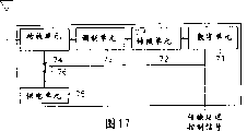
Mobile telephone terminal functional unit 61 and 62, and simply Radio Terminal Function unit 63 and 64 needn't constitute as shown in Figure 16 like that, can consider some modifications.For example, Figure 17 is an expression mobile telephone terminal functional unit 61 and 62, and the block diagram of first modification of the internal structure of simple Radio Terminal Function unit 63 and 64.In Figure 17, different with Figure 16, be provided for digital units 71 from the transmission delay control signal of transmission delay control unit 65, also be provided for transmission delay unit 76.
In first modification, because needn't be from digital units 71 to transmission delay unit 76 output transmission delay signals, the therefore processing load that can alleviate digital units 71.
Figure 18 is an expression mobile telephone terminal functional unit 61 and 62, and the block diagram of second modification of the internal structure of simple Radio Terminal Function unit 63 and 64.In Figure 18, different with Figure 16, only be provided for transmission delay unit 76 from the transmission delay control signal of transmission delay control unit 65.Identical among the operation of transmission delay unit 76 and Figure 16, still, because the transmission delay control signal is not transfused to digital units 71, so digital units 71 is carried out signal processing all the time.
So even receive the transmission delay instruction, digital units 71, D/A converting unit 72 and modulating unit 73 continue operation.But, because to power amplifier unit 74 power supply, therefore emitting radio wave not.
In second modification, to compare with the example shown in Figure 16 and Figure 17, energy consumption increases, but the processing load of digital units 71 is further alleviated.
(the 7th embodiment)
In the 7th embodiment, realize the detection of the fault of simple Radio Terminal Function unit.
Figure 19 is a block diagram of representing the schematic construction of wireless communication terminal according to a seventh embodiment of the invention.In Figure 19, with identical Reference numeral represent with Figure 15 in similar assembly, below the main difference of describing.
Wireless communication terminal among Figure 19 has and detects the fault detection unit 66 and 67 whether simple Radio Terminal Function unit 63 or 64 exists fault respectively.When simple Radio Terminal Function unit 63 and 64 is arbitrary when having fault, corresponding fault detection unit 66 or 67 provides the transmission delay signal to transmission delay control unit 65.
When from mobile telephone terminal functional unit 61 and 62, and arbitrary in the simple Radio Terminal Function unit 63 and 64 is when receiving the transmission delay signal, transmission delay control unit 65 is to all mobile telephone terminal functional units 61 and 62, and simple Radio Terminal Function unit 63 and 64 provides the transmission delay control signal.
According to mode identical shown in Figure 16-Figure 18, form mobile telephone terminal functional unit 61 and 62, and simple Radio Terminal Function unit 63 and 64.
Figure 20 is expression simple Radio Terminal Function unit 63 and 64, and detects the fault detection unit 66 of the fault in simple Radio Terminal Function unit 63 and 64 and the block diagram of 67 internal structure.In Figure 20, represented wherein to constitute as shown in Figure 16 the example of simple Radio Terminal Function unit 63 and 64, but also can as shown in Figure 17 or Figure 18, constitute simple Radio Terminal Function unit 63 and 64.
Fault detection unit 66 and 67 comprises whether the digital units of judging in the corresponding simple Radio Terminal Function unit 63 or 64 71 exists the Watch Dog Timer 77 of fault and judge whether power amplifier unit 74 exists the through-put power measuring unit 78 of fault.
Through-put power measuring unit 78 monitors the amplifying power in the power amplifier units 74, if amplifying power not within setting, through-put power measuring unit 78 judges that there is fault in power amplifier units 74 so.
When Watch Dog Timer 77 and through-put power measuring unit 78 judge that one of at least when having fault, fault detection unit 66 and 67 provides the transmission delay signal to transmission delay control unit 65.
When receiving the transmission delay signal, transmission delay control unit 65 is to all mobile telephone terminal functional units 61 and 62, and simply Radio Terminal Function unit 63 and 64 provides the transmission delay control signal, receives that the corresponding functional unit instruction transmission delay unit 76 of this signal delays from power supply unit 75 to power amplifier unit 74 power supplies.
As mentioned above, in the 7th embodiment, owing to be provided with the fault detection unit 66 and 67 that detects the fault in simple Radio Terminal Function unit 63 and 64, therefore when simple Radio Terminal Function unit 63 and 64 is arbitrary when having fault, can delay from all mobile telephone terminal functional units 61 and 62, and simple Radio Terminal Function unit 63 and 64 emitting radio wave.Thereby, even when simple Radio Terminal Function unit 63 and 64, fault effects in for example wireless LNA system or bluetooth (TM) system mobile telephone terminal functional unit 61 and 62 o'clock, owing to, therefore can avoid influence to external world not from mobile telephone terminal functional unit 61 and 62 emitting radio wave.
Among each embodiment of Miao Shuing, be included in the mobile telephone terminal functional unit 61 and 62 in the wireless communication terminal in the above, and the number of simple Radio Terminal Function unit 63 and 64 is not limited especially.Mobile telephone terminal functional unit 61 and 62, and simple Radio Terminal Function unit 63 and 64 can be disposed by software-defined radio.Mobile telephone terminal functional unit 61 and 62, and simple Radio Terminal Function unit 63 and 64 needs to provide one respectively at least.In addition, to mobile telephone terminal functional unit 61 and 62, and the type of the concrete wireless system of simple Radio Terminal Function unit 63 and 64 is not particularly limited.
Claims (20)
1, a kind of wireless communication terminal comprises:
Software-defined radio, has first radio-cell that transmits wireless signal, the signal processor that comprises the reconfigurable unit of the signal processing content that can change the wireless signal that transmits by described first radio-cell, control described reconfigurable unit the signal processing content the signal processing controller that reconfigures and control first controller of described signal processor and described signal processing controller;
The honeycomb type wireless device has with the honeycomb method and transmits second radio-cell of wireless signal and control second controller of described second radio-cell; With
Between described first and second controllers, transmit the control signal wire of setting up the necessary control signal of communication.
2, according to the described wireless communication terminal of claim 1, wherein said control signal wire transmits the described control signal that the described honeycomb type radio-cell of indication has taked to transmit restriction from described second controller to described first controller.
3, according to the described wireless communication terminal of claim 1, wherein said control signal comprises one of the following at least: and the information of wireless channel structurally associated, with the relevant information of carrier structure of control, system operation information, congested restricted information, country code information, type of wireless system information, common calling zone type information, channel rebulids solicited message, channel allocation notice, and channel allocation.
4, a kind of wireless communication terminal comprises:
First software-defined radio, has first radio-cell that transmits wireless signal, the signal processor that comprises the reconfigurable unit of the signal processing content that can change the wireless signal that transmits by described first radio-cell, control described reconfigurable unit the signal processing content the signal processing controller that reconfigures and control first controller of described first radio-cell, described signal processor and described signal processing controller;
Second software-defined radio has second controller that transmits second radio-cell of wireless signal and control described second radio-cell in the scope that is narrower than honeycomb type equipment; With
Between described first and second controllers, transmit the control signal wire of setting up the necessary control signal of communication.
5, according to the described wireless communication terminal of claim 4, wherein said control signal wire transmits the described control signal that the described honeycomb type wireless device of indication has taked to transmit restriction from described second controller to described first controller.
6, according to the described wireless communication terminal of claim 4, wherein said control signal comprises one of the following at least: and the information of wireless channel structurally associated, with the relevant information of carrier structure of control, system operation information, congested restricted information, country code information, type of wireless system information, common calling zone type information, channel rebulids solicited message, channel allocation notice, and channel allocation.
7, a kind of wireless communication terminal comprises:
Software-defined radio, has first radio-cell that transmits wireless signal, the signal processor that comprises the reconfigurable unit of the signal processing content that can change the wireless signal that transmits by described first radio-cell, control described reconfigurable unit the signal processing content the signal processing controller that reconfigures and control first controller of described first radio-cell, described signal processor and described signal processing controller;
The honeycomb type wireless device has with the honeycomb method and transmits second radio-cell of wireless signal and control second controller of described second radio-cell;
Simple wireless devices has the 3rd controller that transmits the 3rd radio-cell of wireless signal and control described the 3rd radio-cell in the scope that is narrower than described honeycomb type wireless device; With
Between described first, second and the 3rd controller, transmit the control signal wire of setting up the necessary control signal of communication.
8, according to the described wireless communication terminal of claim 7, wherein said software wireless terminal can play the honeycomb type wireless device; With
Described control signal wire transmits the described control signal that the described software-defined radio of indication has taked to transmit restriction from described first controller to the described second and the 3rd controller.
9, according to the described wireless communication terminal of claim 7, wherein said control signal comprises one of the following at least: and the information of wireless channel structurally associated, with the relevant information of carrier structure of control, system operation information, congested restricted information, country code information, type of wireless system information, common calling zone type information, channel rebulids solicited message, channel allocation notice, and channel allocation.
10, a kind of wireless communication terminal comprises:
The first software wireless terminal, has first radio-cell that transmits wireless signal, first signal processor that comprises the first reconfigurable unit of the signal processing content that can change the wireless signal that transmits by described first radio-cell, control the described first reconfigurable unit the signal processing content first signal processing controller that redefines and control first controller of described first radio-cell, described first signal processing unit and described first signal processing controller;
The second software wireless terminal, has second radio-cell that transmits wireless signal, the secondary signal processor that comprises the second reconfigurable unit of the signal processing content that can change the wireless signal that transmits by described second radio-cell, control the described second reconfigurable unit the signal processing content the secondary signal processing controller that reconfigures and control second controller of described second radio-cell, described secondary signal processing unit and described secondary signal processing controller; With
Between described first and second controllers, transmit the control signal wire of setting up the necessary control signal of communication.
11, according to the described wireless communication terminal of claim 10, wherein said first software-defined radio has the effect that transmits the honeycomb type wireless device of wireless signal with the honeycomb method;
Described second software-defined radio has the effect that transmits the simple wireless devices of wireless signal in the scope that is narrower than the honeycomb method; And
Described control signal wire transmits the described control signal that described first software-defined radio of indication has taked to transmit restriction from described first controller to described second controller.
12,, also be included between the described first and second software wireless terminals to transmit and comprise the interface circuit of described control signal at interior signal according to the described wireless communication terminal of claim 10; And
Wherein said second software-defined radio is connected with described first software-defined radio in separable mode, and by described interface circuit, transmits the signal processing content between described first and second signal processors.
13, according to the described wireless communication terminal of claim 10, wherein said control signal comprises one of the following at least: and the information of wireless channel structurally associated, with the relevant information of carrier structure of control, system operation information, congested restricted information, country code information, type of wireless system information, common calling zone type information, channel rebulids solicited message, channel allocation notice, and channel allocation.
14, a kind of wireless communication terminal comprises:
Corresponding under the condition of predesignating, force in first delivery unit that each wireless system at least one wireless system of transmission delay responsibility of radio wave is provided with at least one to it;
Corresponding to not forcing in second delivery unit that each wireless system at least one wireless system of transmission delay responsibility of radio wave is provided with at least one to it; With
When the described transmission delay responsibility of at least one foundation in described first delivery unit stopped the transmission of radio wave, other described first and second delivery unit provided the transmission delay controller of the transmission delay control signal of the transmission delay of indicating radio wave to all;
Described first and second delivery units that receive described transmission delay control signal have the transmission delay unit of the transmission that delays radio wave respectively.
15, according to the described wireless communication terminal of claim 14, wherein said first delivery unit comprises:
Receive described transmission delay control signal, and carry out digital signal processing to produce the digital units of digital transmission signal;
Described digital transmission signal is converted to the D/A converter of analogue transmission signal;
Described analogue transmission signal is carried out modulation treatment to produce the modulator of modulation signal;
Described modulation signal is carried out the power amplifier of power amplification; With
Power supply unit to described at least power supply unit power supply;
Wherein when receiving described transmission delay control signal, described digital units delays the generation of described digital transmission signal to be handled, and to described transmission delay unit output transmission delay signal.
16, according to the described wireless communication terminal of claim 14, wherein said first delivery unit comprises:
Receive described transmission delay control signal, and carry out digital signal processing to produce the digital units of digital transmission signal;
Described digital transmission signal is converted to the D/A converter of analogue transmission signal;
Described analogue transmission signal is carried out modulation treatment to produce the modulator of modulation signal;
Described modulation signal is carried out the power amplifier of power amplification; With
Power supply unit to described at least power amplifier power supply;
Wherein when receiving described transmission delay control signal, described digital units delays the generation of described digital transmission signal to be handled; And
When receiving described transmission delay control signal, described transmission delay unit delays to described at least power amplifier power supply.
17, according to the described wireless communication terminal of claim 14, wherein said first delivery unit comprises:
Carry out Digital Signal Processing to produce the digital units of digital transmission signal;
Described digital transmission signal is converted to the D/A converter of analogue transmission signal;
Described analogue transmission signal is carried out modulation treatment to produce the modulator of modulation signal;
Carry out the power amplifier of the power amplification of described modulation signal; With
To the power supply unit of described at least power amplifier power supply,
Wherein when receiving described transmission delay control signal, described transmission delay unit delays to described at least power amplifier power supply.
18, a kind of wireless communication terminal comprises:
Corresponding under the condition of predesignating, force in first delivery unit that each wireless system at least one wireless system of transmission delay responsibility of radio wave is provided with at least one to it;
Corresponding to not forcing in second delivery unit that each wireless system at least one wireless system of transmission delay responsibility of radio wave is provided with at least one to it;
In the tracer that is provided with corresponding to each described second delivery unit at least one, described tracer detects the fault of corresponding second delivery unit; With
When being defined as breaking down by in the described tracer at least one, provide the transmission delay controller of transmission delay control signal to the first and second all delivery units,
Wherein said first and second delivery units have when receiving described transmission delay control signal, delay the transmission delay unit of the transmission of radio wave.
19, according to the described wireless communication terminal of claim 18, wherein said second delivery unit comprises:
The combine digital signal processing to be producing digital transmission signal, and every the digital units of scheduled time output function status report signal;
Described digital transmission signal is converted to the D/A converter of analogue transmission signal;
Described analogue transmission signal is carried out modulation treatment to produce the modulator of modulation signal;
Described modulation signal is carried out the power amplifier of power amplification; With
To the power supply unit of described at least power amplifier power supply,
Wherein said tracer comprises:
According to whether receiving described Operation Status Report signal, determine the first fault determining unit whether described digital units breaks down every the scheduled time; With
Measure the amplifying power of described power amplifier, and according to measured value whether in the regulation power bracket, determine whether the second fault determining unit that breaks down; And
When the described first and second fault determining units one of were at least determined to break down, described transmission delay controller was exported described transmission delay control signal.
20, according to the described wireless communication terminal of claim 19, wherein when not receiving described Operation Status Report signal every the scheduled time, the described first fault determining unit is determined to break down; With
When in the scope of the setting that the described amplifying power of described power amplifier is not being predesignated, the described second fault determining unit is determined to break down.
Applications Claiming Priority (4)
| Application Number | Priority Date | Filing Date | Title |
|---|---|---|---|
| JP2002285809A JP4045158B2 (en) | 2002-09-30 | 2002-09-30 | Wireless communication terminal |
| JP287233/2002 | 2002-09-30 | ||
| JP2002287233A JP3779252B2 (en) | 2002-09-30 | 2002-09-30 | Multi-mode wireless terminal device |
| JP285809/2002 | 2002-09-30 |
Publications (1)
| Publication Number | Publication Date |
|---|---|
| CN1498009A true CN1498009A (en) | 2004-05-19 |
Family
ID=31980648
Family Applications (1)
| Application Number | Title | Priority Date | Filing Date |
|---|---|---|---|
| CNA03160191XA Pending CN1498009A (en) | 2002-09-30 | 2003-09-29 | Radio Communication terminal |
Country Status (3)
| Country | Link |
|---|---|
| US (1) | US20040063425A1 (en) |
| EP (1) | EP1404060A3 (en) |
| CN (1) | CN1498009A (en) |
Cited By (1)
| Publication number | Priority date | Publication date | Assignee | Title |
|---|---|---|---|---|
| CN101120562B (en) * | 2005-02-17 | 2010-09-29 | 三星电子株式会社 | Correlation unit for use in software-defined wireless communication systems and method |
Families Citing this family (48)
| Publication number | Priority date | Publication date | Assignee | Title |
|---|---|---|---|---|
| US6782208B1 (en) * | 1999-11-16 | 2004-08-24 | Motorola, Inc. | Wireless communication device and method having coordinated primary and secondary transmitters |
| US7092733B2 (en) * | 2001-01-25 | 2006-08-15 | Kabushiki Kaisha Toshiba | Mobile radio communication apparatus capable to plurality of radio communication systems |
| US7885409B2 (en) | 2002-08-28 | 2011-02-08 | Rockwell Collins, Inc. | Software radio system and method |
| US20060046716A1 (en) * | 2004-08-25 | 2006-03-02 | Padcom, Inc. | Multi-network seamless roaming through a software-defined-radio |
| DE102004047368A1 (en) * | 2004-09-29 | 2006-03-30 | Siemens Ag | A radio-based communication device and method for updating a radio-based communication device |
| US7193435B2 (en) * | 2005-02-04 | 2007-03-20 | Itt Manufacturing Enterprises, Inc. | Programmable application specific integrated circuit for communication and other applications |
| JP4602187B2 (en) * | 2005-02-16 | 2010-12-22 | パナソニック株式会社 | Multi-mode communication device |
| US7856611B2 (en) * | 2005-02-17 | 2010-12-21 | Samsung Electronics Co., Ltd. | Reconfigurable interconnect for use in software-defined radio systems |
| US7668992B2 (en) * | 2005-02-17 | 2010-02-23 | Samsung Electronics Co., Ltd. | Context-based operation reconfigurable instruction set processor and method of operation |
| US7769912B2 (en) * | 2005-02-17 | 2010-08-03 | Samsung Electronics Co., Ltd. | Multistandard SDR architecture using context-based operation reconfigurable instruction set processors |
| FR2885431A1 (en) * | 2005-05-03 | 2006-11-10 | France Telecom | METHOD FOR RECONFIGURING AN INFORMATION PROCESSING UNIT OF A TERMINAL |
| US7941248B1 (en) * | 2005-08-03 | 2011-05-10 | Rockwell Collins, Inc. | Method and apparatus for implementing and managing avionics functions |
| US8126030B2 (en) * | 2005-08-31 | 2012-02-28 | Motorola Mobility, Inc. | Multi-mode wireless communication device and method |
| US7784029B2 (en) * | 2005-09-30 | 2010-08-24 | Microsoft Corporation | Network service for modularly constructing a software defined radio |
| US7681239B2 (en) * | 2005-09-30 | 2010-03-16 | Microsoft Corporation | Modularly constructing a software defined radio |
| US8396041B2 (en) | 2005-11-08 | 2013-03-12 | Microsoft Corporation | Adapting a communication network to varying conditions |
| US7752530B2 (en) * | 2005-11-10 | 2010-07-06 | Samsung Electronics Co., Ltd. | Apparatus and method for a collision-free parallel turbo decoder in a software-defined radio system |
| US7809410B2 (en) | 2005-11-15 | 2010-10-05 | Harris Corporation | Power management system for SCA based software defined radio and related method |
| US8381047B2 (en) | 2005-11-30 | 2013-02-19 | Microsoft Corporation | Predicting degradation of a communication channel below a threshold based on data transmission errors |
| US7720506B1 (en) | 2006-07-28 | 2010-05-18 | Rockwell Collins, Inc. | System and method of providing antenna specific front ends for aviation software defined radios |
| US7831255B1 (en) | 2006-07-31 | 2010-11-09 | Rockwell Collins, Inc. | System and method of providing automated availability and integrity verification for aviation software defined radios |
| GB2446623B (en) * | 2007-02-19 | 2009-07-15 | Motorola Inc | A heterogeneous wireless communication system and a method of operation therefor |
| ATE543261T1 (en) * | 2008-02-19 | 2012-02-15 | Nxp Bv | SOFTWARE DEFINED RADIO DEVICE |
| US20090222832A1 (en) * | 2008-02-29 | 2009-09-03 | Dell Products, Lp | System and method of enabling resources within an information handling system |
| GB2460417B (en) * | 2008-05-28 | 2011-04-06 | Mirics Semiconductor Ltd | Broadcast receiver system |
| US20100035562A1 (en) * | 2008-08-05 | 2010-02-11 | Motorola, Inc. | Method and System for Signal Processing and Transmission |
| US20100033433A1 (en) * | 2008-08-08 | 2010-02-11 | Dell Products, Lp | Display system and method within a reduced resource information handling system |
| US8134565B2 (en) * | 2008-08-08 | 2012-03-13 | Dell Products, Lp | System, module and method of enabling a video interface within a limited resource enabled information handling system |
| WO2010019169A1 (en) * | 2008-08-15 | 2010-02-18 | Lsi Corporation | Rom list-decoding of near codewords |
| US8863268B2 (en) * | 2008-10-29 | 2014-10-14 | Dell Products, Lp | Security module and method within an information handling system |
| US9407694B2 (en) * | 2008-10-30 | 2016-08-02 | Dell Products, Lp | System and method of polling with an information handling system |
| US8855025B2 (en) | 2008-11-04 | 2014-10-07 | Broadcom Corporation | Management unit network for collaboratively managing a plurality of multiservice communication devices |
| US8185099B2 (en) | 2008-11-04 | 2012-05-22 | Broadcom Corporation | Service aggregator for allocating resources to a plurality of multiservice communication devices |
| US8467305B2 (en) | 2008-11-04 | 2013-06-18 | Broadcom Corporation | Multiservice communication device with dedicated environmental monitoring |
| US8195143B2 (en) | 2008-11-04 | 2012-06-05 | Broadcom Corporation | Management unit for facilitating inter-network hand-off for a multiservice communication device |
| US8131220B2 (en) | 2008-11-04 | 2012-03-06 | Broadcom Corporation | Management unit for managing a plurality of multiservice communication devices |
| US8521222B2 (en) | 2008-11-04 | 2013-08-27 | Broadcom Corporation | Multiservice communication device with dedicated control channel |
| US8358978B2 (en) | 2008-11-04 | 2013-01-22 | Broadcom Corporation | Multiservice communication device with cognitive radio transceiver |
| US8265690B2 (en) | 2008-11-04 | 2012-09-11 | Broadcom Corporation | Multiservice communication device with logical control channel |
| US8923774B2 (en) | 2008-11-04 | 2014-12-30 | Broadcom Corporation | Management unit with local agent |
| US20100261500A1 (en) * | 2009-04-09 | 2010-10-14 | Broadcom Corporation | Multiple frequency band multiple standard information signal modular baseband processing module |
| US8312346B2 (en) | 2009-05-01 | 2012-11-13 | Mirics Semiconductor Limited | Systems and methods for communications |
| US8369811B2 (en) * | 2009-07-17 | 2013-02-05 | Dell Products, Lp | System and method for radio antenna sharing in an information handling system |
| US8218940B2 (en) | 2009-08-28 | 2012-07-10 | Dell Products, Lp | System and method for managing multiple independent graphics sources in an information handling system |
| US20110105094A1 (en) * | 2009-10-29 | 2011-05-05 | Microsoft Corporation | Location integration in software defined radio |
| US8457673B2 (en) * | 2010-10-11 | 2013-06-04 | Motorola Mobility Llc | Method and apparatus for radio frequency fingerprint distribution |
| US9748979B2 (en) | 2014-10-04 | 2017-08-29 | Taphere! Technology, Llc | System for providing software defined radio on a device |
| FR3091088B1 (en) * | 2018-12-21 | 2021-05-14 | Inst Mines Telecom | "PROCESS FOR PROVIDING RADIOMOBILE CONNECTIVITY IN A SPACE CONFINED BY AN EXTERNAL TELEVISION ANTENNA AND ASSOCIATED SYSTEM" |
Family Cites Families (11)
| Publication number | Priority date | Publication date | Assignee | Title |
|---|---|---|---|---|
| CA2154318A1 (en) * | 1994-08-25 | 1996-02-26 | Richard David Poole | Adaptable radio telephone handset |
| EP0909043A4 (en) * | 1997-03-04 | 2001-11-14 | Mitsubishi Electric Corp | Dual-mode mobile telephone terminal |
| US5966667A (en) * | 1997-07-14 | 1999-10-12 | Motorola, Inc. | Dual mode communication device and method |
| JP3161599B2 (en) * | 1998-07-10 | 2001-04-25 | 日本電気株式会社 | Mobile phone system |
| US6052600A (en) * | 1998-11-23 | 2000-04-18 | Motorola, Inc. | Software programmable radio and method for configuring |
| WO2001006803A1 (en) * | 1999-07-16 | 2001-01-25 | Mitsubishi Denki Kabushiki Kaisha | Mobile communication terminal device |
| US6768901B1 (en) * | 2000-06-02 | 2004-07-27 | General Dynamics Decision Systems, Inc. | Dynamic hardware resource manager for software-defined communications system |
| AU783921B2 (en) * | 2000-11-16 | 2005-12-22 | Symbol Technologies, Inc. | Coexistence techniques in wireless networks |
| JP2002291011A (en) * | 2001-03-23 | 2002-10-04 | Toshiba Corp | Radio equipment and handover control method for the same |
| US6954446B2 (en) * | 2002-06-25 | 2005-10-11 | Motorola, Inc. | Multiple mode RF communication device |
| US7404074B2 (en) * | 2002-07-12 | 2008-07-22 | Sca Technica, Inc. | Self-booting software defined radio module |
-
2003
- 2003-09-29 US US10/671,469 patent/US20040063425A1/en not_active Abandoned
- 2003-09-29 CN CNA03160191XA patent/CN1498009A/en active Pending
- 2003-09-30 EP EP03256149A patent/EP1404060A3/en not_active Withdrawn
Cited By (1)
| Publication number | Priority date | Publication date | Assignee | Title |
|---|---|---|---|---|
| CN101120562B (en) * | 2005-02-17 | 2010-09-29 | 三星电子株式会社 | Correlation unit for use in software-defined wireless communication systems and method |
Also Published As
| Publication number | Publication date |
|---|---|
| US20040063425A1 (en) | 2004-04-01 |
| EP1404060A3 (en) | 2005-11-23 |
| EP1404060A2 (en) | 2004-03-31 |
Similar Documents
| Publication | Publication Date | Title |
|---|---|---|
| CN1498009A (en) | Radio Communication terminal | |
| CN1248427C (en) | Communication system, communication control equipment and terminal equipment | |
| CN1251444C (en) | Construction method of radio network system and radio transmission device | |
| CN1099211C (en) | System for communicating messages via forward overhead control channel | |
| CN1299523C (en) | Radio link parameter updating method in mobile communication system | |
| CN1297173C (en) | Mobile communication system, resource switching method thereof, network control apparatus included therein, and network mcontrol method | |
| CN1806229A (en) | Conflict management program, storage medium for conflict management program storage, conflict management method, and electronic apparatus | |
| CN1992928A (en) | Apparatus and method for resetting physical channel | |
| CN1535045A (en) | Communication terminal, base station, server, network system and switching method | |
| CN1729709A (en) | Cordless communication network and flow control methods | |
| CN1846361A (en) | Apparatus and a method for controlling operational states of a media access control layer in a broadband wireless access communication system | |
| CN1754396A (en) | The system and the method that are used for mobile communication | |
| CN1305257C (en) | Radio communication system, radio communication control method, radio communication apparatus, radio communication apparatus control method, and computer program | |
| CN1344096A (en) | Integrated mobile telephone, GPS and blueteeth compound terminal and control method thereof | |
| CN1386028A (en) | Portable communication and radio communication system thereof | |
| CN101053184A (en) | Enhanced radio link control error handling | |
| CN1723676A (en) | Communication system, radio communication terminal, and radio base station | |
| CN1889547A (en) | Base band unit ring cascade resource back-up method and base band unit | |
| CN1905749A (en) | Communication terminal and its communication method | |
| CN1708159A (en) | Radio communication terminal, radio base station, and radio communication system | |
| CN1705390A (en) | Communication terminal and communication method thereof | |
| CN1842975A (en) | Mobile station | |
| CN1852347A (en) | Dff-line fault information report method, device and off-line fault reason positioning system | |
| CN1555616A (en) | Radio terminal apparatus and its reception control program | |
| CN1197407C (en) | Method for performing call origination within communication system |
Legal Events
| Date | Code | Title | Description |
|---|---|---|---|
| C06 | Publication | ||
| PB01 | Publication | ||
| C10 | Entry into substantive examination | ||
| SE01 | Entry into force of request for substantive examination | ||
| AD01 | Patent right deemed abandoned | ||
| C20 | Patent right or utility model deemed to be abandoned or is abandoned |