JP5275609B2 - A device for selecting and classifying fiber sliver made of woven fiber, especially for fiber classification or fiber selection - Google Patents
A device for selecting and classifying fiber sliver made of woven fiber, especially for fiber classification or fiber selection Download PDFInfo
- Publication number
- JP5275609B2 JP5275609B2 JP2007272855A JP2007272855A JP5275609B2 JP 5275609 B2 JP5275609 B2 JP 5275609B2 JP 2007272855 A JP2007272855 A JP 2007272855A JP 2007272855 A JP2007272855 A JP 2007272855A JP 5275609 B2 JP5275609 B2 JP 5275609B2
- Authority
- JP
- Japan
- Prior art keywords
- roller
- fiber
- nipper
- combing
- clamping
- Prior art date
- Legal status (The legal status is an assumption and is not a legal conclusion. Google has not performed a legal analysis and makes no representation as to the accuracy of the status listed.)
- Expired - Fee Related
Links
- 239000000835 fiber Substances 0.000 title claims description 116
- 230000002093 peripheral effect Effects 0.000 claims description 13
- 230000033001 locomotion Effects 0.000 description 21
- 238000000605 extraction Methods 0.000 description 7
- 238000000034 method Methods 0.000 description 7
- 239000002657 fibrous material Substances 0.000 description 6
- 241000347389 Serranus cabrilla Species 0.000 description 5
- 230000001133 acceleration Effects 0.000 description 4
- 239000000428 dust Substances 0.000 description 4
- 238000004140 cleaning Methods 0.000 description 3
- 230000006835 compression Effects 0.000 description 3
- 238000007906 compression Methods 0.000 description 3
- 239000004744 fabric Substances 0.000 description 3
- 238000012546 transfer Methods 0.000 description 3
- 229920000742 Cotton Polymers 0.000 description 2
- 230000000712 assembly Effects 0.000 description 2
- 238000000429 assembly Methods 0.000 description 2
- 238000004519 manufacturing process Methods 0.000 description 2
- 238000007781 pre-processing Methods 0.000 description 2
- 238000007790 scraping Methods 0.000 description 2
- 238000000926 separation method Methods 0.000 description 2
- 238000007873 sieving Methods 0.000 description 2
- 238000009987 spinning Methods 0.000 description 2
- 229910000831 Steel Inorganic materials 0.000 description 1
- 238000013459 approach Methods 0.000 description 1
- 230000015572 biosynthetic process Effects 0.000 description 1
- 230000001914 calming effect Effects 0.000 description 1
- 230000015556 catabolic process Effects 0.000 description 1
- 210000001520 comb Anatomy 0.000 description 1
- 239000000356 contaminant Substances 0.000 description 1
- 238000006731 degradation reaction Methods 0.000 description 1
- 238000011161 development Methods 0.000 description 1
- 230000018109 developmental process Effects 0.000 description 1
- 238000010586 diagram Methods 0.000 description 1
- 238000007599 discharging Methods 0.000 description 1
- 230000000694 effects Effects 0.000 description 1
- 210000003746 feather Anatomy 0.000 description 1
- 238000003780 insertion Methods 0.000 description 1
- 230000037431 insertion Effects 0.000 description 1
- 230000001788 irregular Effects 0.000 description 1
- 238000005304 joining Methods 0.000 description 1
- 239000000463 material Substances 0.000 description 1
- 239000002184 metal Substances 0.000 description 1
- 239000000203 mixture Substances 0.000 description 1
- 238000007383 open-end spinning Methods 0.000 description 1
- 238000002360 preparation method Methods 0.000 description 1
- 230000001737 promoting effect Effects 0.000 description 1
- 230000001105 regulatory effect Effects 0.000 description 1
- 230000000717 retained effect Effects 0.000 description 1
- 238000004826 seaming Methods 0.000 description 1
- 239000010959 steel Substances 0.000 description 1
- 238000011144 upstream manufacturing Methods 0.000 description 1
- 238000004804 winding Methods 0.000 description 1
- 210000002268 wool Anatomy 0.000 description 1
Images


Classifications
-
- D—TEXTILES; PAPER
- D01—NATURAL OR MAN-MADE THREADS OR FIBRES; SPINNING
- D01G—PRELIMINARY TREATMENT OF FIBRES, e.g. FOR SPINNING
- D01G19/00—Combing machines
- D01G19/06—Details
-
- D—TEXTILES; PAPER
- D01—NATURAL OR MAN-MADE THREADS OR FIBRES; SPINNING
- D01G—PRELIMINARY TREATMENT OF FIBRES, e.g. FOR SPINNING
- D01G19/00—Combing machines
-
- D—TEXTILES; PAPER
- D01—NATURAL OR MAN-MADE THREADS OR FIBRES; SPINNING
- D01G—PRELIMINARY TREATMENT OF FIBRES, e.g. FOR SPINNING
- D01G19/00—Combing machines
- D01G19/06—Details
- D01G19/14—Drawing-off and delivery apparatus
- D01G19/18—Roller, or roller and apron, devices, e.g. operating to draw-off fibres continuously
Description
本発明は、特にコーミング・デバイスである繊維分類デバイスに対して供給手段により供給された織物繊維から成る繊維スライバを繊維分類もしくは繊維選択する装置に関する。そのような装置は、上記繊維スライバの自由端部から所定距離にて該繊維スライバを挟持する挟持デバイスが配備されており、たとえば短繊維、ネップ、塵埃などの非挟持構成要素を上記繊維スライバの上記自由端部から解(ほぐ)して除去するために挟持部位から上記自由端部にかけてコーミング作用を生成する機械的生成手段が存在する。 The present invention relates to an apparatus for classifying or selecting a fiber sliver composed of woven fibers supplied by a supply means to a fiber classification device which is a combing device. Such an apparatus is provided with a clamping device that clamps the fiber sliver at a predetermined distance from the free end of the fiber sliver. For example, non-clamping components such as short fibers, nep, dust, etc. There is a mechanical generating means for generating a combing action from the clamping part to the free end for unwinding and removing from the free end.
実際問題としてコーミング機械は、綿繊維または羊毛繊維に含まれる天然の夾雑物を遊離させるべく、且つ、繊維スライバの繊維を平行化すべく使用される。その目的のために、予め準備された繊維スライバが新羽機構の把持部の間に挟持され、それにより、”繊維タフト”として知られる繊維の一定の短寸部分がニッパ機構の把持部の前方に突出するようになる。ニードル針布または歯付き針布により縁部形成されたコーミング・ローラ用コーミング・セグメントにより、繊維タフトはコーミングされて清浄化される。取出しデバイスは通常は逆回転する2個のローラから成り、これらのローラは、コーミングされた繊維タフトを把持して該タフトを前方へと搬送する。 In practice, combing machines are used to release natural contaminants contained in cotton or wool fibers and to parallelize the fibers of the fiber sliver. To that end, a pre-prepared fiber sliver is sandwiched between the gripping parts of the new feather mechanism so that a certain short portion of the fiber known as the “fiber tuft” is in front of the gripping part of the nipper mechanism. Protruding. The fiber tufts are combed and cleaned by combing segments for combing rollers, which are edged by a needle or toothed garment. The take-out device usually consists of two counter-rotating rollers that grip the combed fiber tuft and carry it forward.
短繊維、ネップ、塵埃および他の構成要素を繊維混合物から分離するために、ラップ巻回物の形態をなしている繊維材料を機械的梳き取りのためのコーミング機械に供給することが知られている。ラップ・ウェブの端部はニッパにより挟持され、挟持線を越えて突出する端部は円形コームのコーム針布により機械的に梳き取り処理される。梳き取り処理された繊維タフトは次に取り外しローラ対まで移送され、そこで、繊維タフトは、凝集性ウェブへと形成され、すなわち”継ぎ合わせ”される。繊維タフトが上記取り外しローラにより上記ニッパから取り外されるときに、ラップから切離された端部もまた機械的な頂部コームを通して引張られることから、短繊維、ネップ、塵埃および他の不都合な構成要素は、コーミングされたウェブには可能な限り残存しない。公知のコーミング方法の欠点は特に、動作サイクルの間において大きな塊(mass)を加速および減速させる必要があるという動作の不連続様式である。 It is known to supply fiber material in the form of a wrap wrap to a combing machine for mechanical scraping to separate short fibers, nep, dust and other components from the fiber mixture Yes. The end of the wrap web is pinched by a nipper, and the end protruding beyond the pinning line is mechanically scraped off by a comb comb cloth of a circular comb. The chopped fiber tuft is then transferred to a pair of removal rollers where the fiber tuft is formed into a cohesive web, ie "seamed". When the fiber tuft is removed from the nipper by the removal roller, the end cut away from the wrap is also pulled through the mechanical top comb, so that short fibers, nep, dust and other disadvantageous components are , As little as possible on the combed web. A disadvantage of the known combing method is in particular the discontinuous mode of operation in which large masses need to be accelerated and decelerated during the operating cycle.
特に大きなニップ速度の場合にはニッパ・アセンブリの前後の揺動運動が相当な振動を引き起こす。このことは、一方では、駆動要素および軸受要素が適切に安定的な構造とされることを必要とし、他方では、上記機械のフレーム構造と、該機械が取付けられる基部とに対して厳しい要件を課すことになる。 Particularly at high nip speeds, the swinging motion of the nipper assembly back and forth causes considerable vibration. This, on the one hand, requires that the drive and bearing elements be properly stable structures and, on the other hand, places strict requirements on the frame structure of the machine and the base on which the machine is mounted. Will be imposed.
部分的に清浄化された繊維をニッパ・ユニットから上記取出しデバイスのローラを用いて取り外すためには、ニッパ機構の各把持部間に保持された繊維タフトまで直線的に又は該タフトまでの円弧の一部に亙って比較的に高重量の取出しデバイスを移動させる必要がある。あるいは、上記ニッパ機構を静止的な取出しローラに向けて移動させる必要がある。通常的に必要とされる450ニップ/分の場合には、移動されつつある大きな塊はコーミング機械全体を高レベルに動的揺動させ、それにより、該コーミング機械の動作速度および生産性が制限される。 In order to remove the partially cleaned fiber from the nipper unit using the roller of the take-out device, the fiber tuft held between each gripping part of the nipper mechanism is linearly or circularly arced to the tuft. There is a need to move a relatively heavy removal device over a portion. Alternatively, it is necessary to move the nipper mechanism toward a stationary take-out roller. In the case of 450 nips / minute, which is normally required, the large mass being moved dynamically swings the entire combing machine to a high level, thereby limiting the speed and productivity of the combing machine. Is done.
更に、習用のコーミング機械の問題は、コーミングされた繊維が夫々逆回転する取出しローラにより取り外されるとき、繊維長の50%までは円形コームにより清浄化されていないことである。と言うのも、コーミング・プロセスの間において、すなわちコーミング・セグメントが通過するときには、繊維はニッパ機構の各把持部間に挟持されていたか、または、搬送方向で見て繊維は上記把持部の背後に配置されていたからである。同様に、繊維のその部分を可及的に清浄化するために、これらの繊維は習用的には、上記取出しローラの正面に配置された頂部コームを通して引張られる。上記頂部コームは、全てのコーミング・ヘッドに対する付加的な構造要素である。 Furthermore, a problem with the conventional combing machine is that when the combed fibers are each removed by a counter-rotating take-off roller, up to 50% of the fiber length is not cleaned by a circular comb. This is because during the combing process, i.e. when the combing segment passes, the fibers were pinched between the grippers of the nipper mechanism, or the fibers are behind the grips as viewed in the transport direction. It is because it was arranged in. Similarly, to clean as much as possible of that portion of the fibers, these fibers are conventionally pulled through a top comb located in front of the pick roller. The top comb is an additional structural element for all combing heads.
下側取り外しローラと上側取り外しローラとから成る取り外しローラ対は、ニッパ装置および円形コームの直近に在る。上記下側取り外しローラは、上記円形コームのコーム尖端の移動軌跡と上記上側取り外しローラとの間に配置されており、さらに、該下側取り外しローラは、上記上側取り外しローラと協働して、コーミング済みスライバに対する挟持ニップを形成する。上記ニッパ機構は、二方向に揺動すべく取付けられる。第1に、ニッパ機構は、上記取り外しローラ対から所定距離において、上記円形コームのコーム尖端の移動軌跡に向けて移動される。その位置において、繊維タフト上記円形コームによりコーミングされる。上記動作が完了したときに、上記ニッパ装置はユニットとして上昇され、それにより、コーミングされたばかりの繊維タフトが上記取り外しローラ対の挟持ニップの正面に到達するようになる。その移動の間において、上記ニッパ装置は上記取り外しローラ・ニップに水平に接近する。その時点において、戻し搬送されたコーミング済みスライバの部分は、新たなコーミング済み繊維タフトの先端と重なり合わされ、各取り外しローラの挟持ニップにおいて圧縮され、該取り外しローラにより取出し方向へと引出され、頂部コームは、コーミングされたばかりの繊維タフトの端部に挿入されて繊維の自由片を梳き取る。上記ニッパ装置の後退移動および上記取り外しローラ対の取出し移動の結果として、コーミング済み繊維タフトは取り外され、送給ローラによって新たな繊維タフトが上記ニッパ装置に供給され、挟持され、且つ、上記円形コームに対するコーミング位置へともたらされる。特に上記ニッパ装置は或る程度の加速を以て非常に大きい多様な運動を実施すべきであるので、斯かる配置構成は欠点となる。故に動作速度は相当に制限され、大きな騒音が発生し、且つ、引き起こされる慣性力によって平均を超える摩耗が生じる。取り外し距離および送給量の調節は、上記機械が静止している間においてのみ行われ得る。更に決定的な欠点は、コーミングされたばかりの繊維タフトの自由端部もまた、その自由繊維先端を前方として、長距離に亙り比較的に高速で移動させる必要があると共に、該自由端部を、戻し移動されたコーミング済みスライバの端部上へと厳密に範囲限定された位置に載置する必要があることである。引き起こされる空気渦流と夫々の空気抵抗とに依存し、繊維タフトは戻し移動されたコーミング済みスライバ上にしばしば不正確に位置決めされるので、繊維タフトを比較的に低速で動作させる必要がある。但しいずれの場合にも、コーミング済みスライバにおいては品質の低下が見られる。公知の装置の更なる欠点は、取り外しローラの前後移動段階における動作の結果として取り外しローラ対と取出しローラとの間に制御されない様式で折畳み部分の形成が生じ、このことは付加的にコーミング・プロセスが中断に帰着することになる。 A pair of removal rollers consisting of a lower removal roller and an upper removal roller is in the immediate vicinity of the nipper device and the circular comb. The lower removal roller is disposed between a movement trajectory of a comb tip of the circular comb and the upper removal roller, and the lower removal roller cooperates with the upper removal roller to perform combing. Form a clamping nip for the used sliver. The nipper mechanism is mounted to swing in two directions. First, the nipper mechanism is moved toward the movement locus of the comb tip of the circular comb at a predetermined distance from the pair of removal rollers. At that position, the fiber tuft is combed by the circular comb. When the operation is complete, the nipper device is raised as a unit so that the just combed fiber tuft reaches the front of the pinching nip of the pair of removal rollers. During that movement, the nipper device approaches the removal roller nip horizontally. At that point, the portion of the combed sliver that has been transported back is overlapped with the tip of the new combed fiber tuft, compressed at the clamping nip of each removal roller, and pulled in the removal direction by the removal roller, and the top comb Is inserted into the end of a newly combed fiber tuft to scrape the free pieces of fiber. As a result of the backward movement of the nipper device and the removal movement of the pair of removal rollers, the combed fiber tuft is removed, a new fiber tuft is supplied to the nipper device by the feeding roller, and is sandwiched, and the circular comb To the combing position for. In particular, the arrangement is a disadvantage because the nipper device should perform a very large variety of movements with some acceleration. The operating speed is therefore considerably limited, loud noise is generated, and the induced inertia causes wear above average. The adjustment of the removal distance and the feed rate can only take place while the machine is stationary. A further decisive disadvantage is that the free end of the newly combed fiber tuft also needs to be moved at a relatively high speed over a long distance with its free fiber tip in front, It is necessary to place it in a strictly limited range on the end of the combed sliver that has been moved back. Depending on the air vortex induced and the respective air resistance, the fiber tufts are often incorrectly positioned on the returned combed sliver, so that the fiber tufts need to be operated relatively slowly. In either case, however, the quality of the combed sliver is reduced. A further disadvantage of the known device is that as a result of the movement of the removal roller in the back-and-forth movement phase, a folding part is formed in an uncontrolled manner between the removal roller pair and the take-off roller, which additionally adds to the combing process. Will result in interruption.
上記ニッパがその前方位置に配置されたとき、ニッパは開放され、梳き取り処理された繊維タフトを取り外しローラ対まで移送する。該タフトは、先行して取り外された繊維タフトと継ぎ合わされる。 When the nipper is placed at its front position, the nipper is opened, and the fiber tuft that has been treated is transferred to the pair of detaching rollers. The tuft is spliced with the previously removed fiber tuft.
公知の綿コーミング・プロセスは不連続プロセスである。ニップ動作の間において、全てのアセンブリおよびそれらの駆動手段およびギヤは、加速、減速され、および、或る場合には再び反転される。大きなニップ速度によって、大きな加速になる。特に、ニッパの運動学、ニッパ移動のためのギヤ、および、取り外しローラの前後移動段階の動きのためのギヤの結果として、大きな加速力が引き起こされる。引き起こされる力および応力は、ニップ速度が大きいほど大きくなる。公知のフラット・コーミング機械はそのニップ速度により性能限界に達し、生産性の増大が妨げられる。更に、不連続な動作様式によれば機械全体における振動が引き起こされ、動的で交互的な応力が生成される。 The known cotton combing process is a discontinuous process. During the nip operation, all assemblies and their drive means and gears are accelerated, decelerated, and in some cases reversed again. A large nip speed results in a large acceleration. In particular, large acceleration forces are caused as a result of the kipper kinematics, the gear for nipper movement and the gear for the back and forth movement of the removal roller. The forces and stresses that are caused increase as the nip speed increases. Known flat combing machines reach their performance limits due to their nip speeds and prevent increased productivity. Furthermore, the discontinuous mode of operation causes vibrations throughout the machine, generating dynamic and alternating stresses.
EP 1 586 682 Aは、たとえば8個のコーミング・ヘッドが次々と同時に動作するというコーミング機械を開示している。これらのコーミング・ヘッドの駆動は、各コーミング・ヘッドに隣接して配置された側方駆動手段により行われる。そのような側方駆動手段は、長手シャフトにより各コーミング・ヘッドの個別要素に駆動可能に接続されたギヤ・ユニットを有している。個々のコーミング・ヘッドにて形成された繊維スライバは、コンベア・テーブル上で次々と、後続の牽伸システムへと移送され、該牽伸システムにおいては、繊維スライバは牽伸されてから組み合わされて一般的なコーミング機械スライバを形成する。上記牽伸システムにおいて作成された繊維スライバは、次に、ファネル・ホィール(巻取器プレート)によりケンス内に投入される。上記コーミング機械の複数個のコーミング・ヘッドは各々、送給デバイスと、枢動的に取付けられた固定位置のニッパ・アセンブリと、上記ニッパ・アセンブリにより供給された繊維タフトを梳き取り処理するコーム・セグメントを有すると共に回転可能に取付けられた円形のコーム(comb)と、頂部コームと、梳き取り処理された繊維タフトを上記ニッパ・アセンブリから取り外す固定位置の取り外しデバイスとを有する。そのようなコーミング機械の欠点は特に、多数の機器が必要とされ且つ時間当たりの製造速度が低いことである。8個の個別のコーミング・ヘッドが在るものの、それらは合計で、8個の送給デバイス、8個の固定位置ニッパ・アセンブリ、コーム・セグメントを備えた8個の円形コーム、8個の頂部コーム、および、8個の取り外しデバイスを有している。特定の問題は、各コーミング・ヘッドの動作の不連続様式であることである。更なる欠点は、大きな質量の加速および反転移動から帰着するものであり、大きな動作速度が不可能であることである。最後に、機械の振動がかなりの量であるので、コーミング済みスライバの投入が不規則になる。更に、下側のニッパ・プレートのニッパ唇部と取外しシリンダの挟持点との間の隔たり即ち距離は、構造的かつ空間的に制限されている。 EP 1 586 682 A discloses a combing machine in which, for example, eight combing heads operate simultaneously one after the other. These combing heads are driven by side driving means arranged adjacent to each combing head. Such lateral drive means have a gear unit that is drivably connected to the individual elements of each combing head by means of a longitudinal shaft. The fiber sliver formed by the individual combing heads is transferred to the subsequent drafting system one after another on the conveyor table, where the fiber sliver is drafted and then combined. Forms a common combing machine sliver. The fiber sliver created in the drafting system is then fed into the can through a funnel wheel (winder plate). A plurality of combing heads of the combing machine each includes a feeding device, a pivotally mounted fixed position nipper assembly, and a comb comb that scrapes and processes the fiber tuft supplied by the nipper assembly. A circular comb having segments and rotatably mounted, a top comb, and a fixed position removal device for removing the wiped fiber tuft from the nipper assembly. The disadvantages of such combing machines are in particular that a large number of devices are required and the production rate per hour is low. Although there are 8 individual combing heads, they total a total of 8 feeding devices, 8 fixed position nipper assemblies, 8 circular combs with comb segments, 8 tops Comb and 8 removal devices. A particular problem is the discontinuous manner of operation of each combing head. A further disadvantage is that large operating speeds are impossible, resulting from large mass acceleration and reversal movement. Finally, the amount of vibration of the machine is so great that the combed sliver loading becomes irregular. Furthermore, the distance between the nipper lip of the lower nipper plate and the clamping point of the removal cylinder is structurally and spatially limited.
故に、本発明の基礎となる課題は、冒頭部にて記述された種類の装置であって、言及された欠点を解消すると共に、特に簡素な手法で、時間当たりに生産される量(生産性)を相当に増大し得ると共に優れたコーミング済みスライバを実現し得るという装置を提供するに在る。 The problem underlying the present invention is therefore an apparatus of the kind described at the outset, which eliminates the disadvantages mentioned and produces in a particularly simple manner the amount produced per hour (productivity). ) Can be considerably increased and an excellent combed sliver can be realized.
この課題は、請求項1の特徴部分の特徴により解決される。
すなわち、1番目の発明によれば、繊維分類デバイスに対して供給手段により供給された織物繊維から成る繊維スライバを繊維分類もしくは繊維選択する装置であって、該装置は、上記繊維スライバの自由端部から所定距離にて該繊維スライバを挟持する挟持デバイスが配備されており、非挟持構成要素を上記繊維スライバの上記自由端部から解して除去するために、挟持部位から上記自由端部にかけてコーミング作用を生成する機械的生成手段が存在するという装置において、回転可能に取付けられた少なくとも一個のローラ(12、13)が上記供給手段(8;10、11、27a、27b、28a、28b)の下流に配置されており、該ローラは、該ローラ(12、13)の周縁部の領域において離間して分布された上記繊維スライバ(16;301〜303)用挟持デバイス(18、19、20;21、22、23)を備えており、コーミング作用を生成する上記生成手段(15、31、32)は上記ローラ(13)に関係付けられており、前記回転可能に取付けられた少なくとも一個のローラ(12、13)は中断されることなしに迅速に連続的に回転することを特徴とする、装置が提供される。
This problem is solved by the features of the characterizing portion of claim 1.
That is, according to the first aspect of the present invention, there is provided an apparatus for classifying or selecting a fiber sliver composed of woven fibers supplied to a fiber classification device by a supply means, the apparatus comprising: A clamping device is provided that clamps the fiber sliver at a predetermined distance from the section, from the clamping site to the free end in order to remove the non-pinching component from the free end of the fiber sliver. In a device in which there is a mechanical generating means for generating a combing action, at least one roller (12, 13) mounted rotatably is said supply means (8; 10, 11, 27a, 27b, 28a, 28b). The fiber sliver is disposed at a downstream side of the roller, and the rollers are spaced apart and distributed in the peripheral region of the rollers (12, 13). 16; 301 to 303) for clamping devices (18, 19, 20; includes a 21, 22, 23), said generation means for generating a combing action (15,31,32) said roller (13) A device is provided, characterized in that the at least one roller (12, 13) mounted in rotation is rapidly and continuously rotated without interruption .
梳き取り処理されるべき繊維束を回転ローラ上で挟持かつ移動させる機能を実施することにより、公知の装置とは異なり、大きな塊を加速および反転移動させることなしに、大きな動作速度(ニップ速度)を達成できる。特に、動作の様式は連続的である。高速のローラが使用されたときには時間当たりの製造速度(生産性)が相当に高められる。このことは、従前の技術範囲では可能とは思われていなかった。更なる利点は、回転的な回転運動は振動の沈静化ならびに当該機械の更に均一な運動シーケンスに帰着することから、優れたコーミング済みスライバに帰着することである。上記隔たりは好適には、構造的に制限されない。この結果として、到来する繊維ラップの送給量がさらに増大されると共に、長寸繊維の分離が減少される。 Unlike the known apparatus, by implementing the function of holding and moving the fiber bundle to be scraped off on the rotating roller, a large operating speed (nip speed) can be achieved without accelerating and reversing the large mass. Can be achieved. In particular, the mode of operation is continuous. When high speed rollers are used, the production rate (productivity) per hour is considerably increased. This was not considered possible in the prior art. A further advantage is that the rotational rotary motion results in a better combed sliver because it results in a vibrational calming and a more uniform motion sequence of the machine. The spacing is preferably not structurally limited. As a result, the incoming fiber wrap feed rate is further increased and the separation of long fibers is reduced.
請求項2乃至23は、本発明の好適な発展例を包含する。
2番目の発明によれば、1番目の発明において、前記供給手段により吐出された繊維スライバを段階的に個別の繊維タフトへと分離する分離手段が配備される。
3番目の発明によれば、2番目の発明において、前記分離手段は回転可能に取付けられた第1ローラを備える。
4番目の発明によれば、3番目の発明において、前記第1ローラは、該第1ローラの周縁部の回りにおいて離間して分布された第1挟持デバイスを備える。
5番目の発明によれば、4番目の発明において、前記第1挟持デバイスは各々、ニッパ・デバイスを有する。
6番目の発明によれば、5番目の発明において、前記ニッパ・デバイスは、回転可能または変位可能に取付けられた把持要素を有する。
7番目の発明によれば、5番目または6番目の発明において、前記ニッパ・デバイスは、固定的に取付けられた対向要素を有する。
8番目の発明によれば、7番目の発明において、前記対向要素は移動可能に取付けられる。
9番目の発明によれば、6番目の発明において、前記把持要素はスプリングの力要素により負荷される。
10番目の発明によれば、8番目の発明において、移動可能に取付けられた前記対向要素はスプリングにより力負荷される。
11番目の発明によれば、4番目から10番目のいずれかの発明において、前記第1ローラに対して軸心的に平行に、回転可能に取付けられた第2ローラが関係付けられる。
12番目の発明によれば、11番目の発明において、前記第1ローラおよび前記第2ローラは相互に逆方向に回転する。
13番目の発明によれば、11番目の発明において、前記第2ローラは、該第2ローラの周縁部の回りに離間して分布された第2挟持デバイスを備える。
14番目の発明によれば、13番目の発明において、前記第2挟持デバイスは各々、ニッパ・デバイスを有する。
15番目の発明によれば、14番目の発明において、前記第2挟持デバイスの前記ニッパ・デバイスは、回転可能または変位可能に取付けられた把持要素を有する。
16番目の発明によれば、14番目の発明において、前記第2挟持デバイスの前記ニッパ・デバイスは、固定的に取付けられた対向要素を有する。
17番目の発明によれば、16番目の発明において、前記第2挟持デバイスの前記対向要素は移動可能に取付けられる。
18番目の発明によれば、17番目の発明において、前記移動可能に取付けられた前記第2挟持デバイスの対向要素はスプリングにより力負荷される。
19番目の発明によれば、11番目の発明において、前記第2ローラに対して軸心的に平行に、回転可能に取付けられた取出しローラが在る。
20番目の発明によれば、19番目の発明において、前記取出しローラの外側円筒状表面は空気通過開口を有する。
21番目の発明によれば、20番目の発明において、前記取出しローラの内部は負圧源に接続される。
22番目の発明によれば、21番目の発明において、前記取出しローラの内側円筒状表面の一部は篩要素(screen element)によりシールされる。
23番目の発明によれば、11番目の発明において、前記第1ローラおよび前記第2ローラは共通ギヤにより駆動可能である。
According to the second invention, in the first invention, a separating means for separating the fiber sliver discharged by the supplying means into individual fiber tufts in stages is provided.
According to a third invention, in the second invention, the separating means comprises a first roller mounted rotatably.
According to a fourth aspect, in the third aspect, the first roller includes a first clamping device that is distributed around the periphery of the first roller.
According to a fifth aspect, in the fourth aspect, each of the first clamping devices has a nipper device.
According to a sixth aspect, in the fifth aspect, the nipper device has a gripping element mounted rotatably or displaceably.
According to a seventh aspect, in the fifth or sixth aspect, the nipper device has an opposing element fixedly attached.
According to an eighth aspect, in the seventh aspect, the opposing element is movably attached.
According to a ninth invention, in the sixth invention, the gripping element is loaded by a force element of a spring.
According to the tenth invention, in the eighth invention, the counter element mounted so as to be movable is force-loaded by a spring.
According to the eleventh invention, in any one of the fourth to tenth inventions, a second roller rotatably attached in parallel to the first roller is related.
According to a twelfth aspect, in the eleventh aspect, the first roller and the second roller rotate in opposite directions.
According to a thirteenth aspect, in the eleventh aspect, the second roller includes a second clamping device that is distributed around the periphery of the second roller.
According to a fourteenth aspect, in the thirteenth aspect, each of the second clamping devices has a nipper device.
According to a fifteenth aspect, in the fourteenth aspect, the nipper device of the second clamping device has a gripping element attached rotatably or displaceably.
According to a sixteenth aspect, in the fourteenth aspect, the nipper device of the second clamping device has an opposing element fixedly attached.
According to a seventeenth aspect, in the sixteenth aspect, the opposing element of the second clamping device is movably attached.
According to the eighteenth aspect, in the seventeenth aspect, the opposing element of the second holding device movably attached is force-loaded by a spring.
According to a nineteenth aspect, in the eleventh aspect, there is a take-out roller rotatably attached in parallel to the second roller in an axial direction.
According to a twentieth aspect, in the nineteenth aspect, the outer cylindrical surface of the take-out roller has an air passage opening.
According to the twenty-first aspect, in the twentieth aspect, the inside of the take-out roller is connected to a negative pressure source.
According to the twenty-second aspect, in the twenty-first aspect, a part of the inner cylindrical surface of the take-out roller is sealed by a screen element.
According to the 23rd invention, in the 11th invention, the first roller and the second roller can be driven by a common gear.
本発明は、以下において図面中に示された好適実施例に関して相当に詳細に記述される。
図1に依ると、コーミング前処理機1は、スライバの送給を受け且つラップを吐出する紡績機械と、相互に平行に配置された2個の送給テーブル4a、4b(軸架)とを有し、送給テーブル4a、4bの各々の下方には(不図示の)繊維スライバを収容する2列のケンス5a、5bが配置されている。ケンス5a、5bから引き出された繊維スライバは方向を変更された後で、相次いで配置されたコーミング前処理機1の2台の牽伸システム6a、6bへと進行する。形成された繊維スライバ・ウェブは、牽伸システム6aからウェブ・テーブル7に案内され、次いで牽伸システム6bの吐出口にては、相互に積み重ねて布置されると共に、牽伸システムにおいて作製された繊維スライバ・ウェブと束ねられる。牽伸システム6aおよび6bの夫々によって、複数本の繊維スライバは組み合わされてラップを形成すると共に一体的に牽伸される。牽伸された複数のラップ(実施例においては2枚のラップが示される)は、相互に重ねて載置されることで二重化される。その様に形成されたラップは、下流のロータ・コーミング機械2の供給デバイス(送給要素)へと直接的に導入される。繊維材料の流れは中断されない。コーミングされた繊維ウェブは、ロータ・コーミング機械2の吐出口にて吐出され、ファネル(図10(a)を参照)を通過してコーマ・スライバを形成し、次いで、下流のスライバ投入デバイス3へと投入される。参照符号Aは、動作方向を表す。
The invention will be described in considerable detail below with reference to preferred embodiments shown in the drawings.
According to FIG. 1, a combing pre-processing machine 1 includes a spinning machine that receives a sliver and discharges a lap, and two feeding tables 4a and 4b (shaft racks) arranged in parallel to each other. Two rows of
オートレベラ牽伸システム50(図2を参照)が、ロータ・コーミング機械2とスライバ投入デバイス3との間に配置され得る。これにより、上記コーマ・スライバは牽伸される。
An auto-leveler drafting system 50 (see FIG. 2) can be arranged between the
更なる構成に依れば、1台以上のロータ・コーミング機械2が配備される。例えば2台のロータ・コーミング機械2aおよび2bが存在する場合には、吐出された2本のコーマ・スライバ17は、下流のオートレベラ牽伸システム50を一体的に通過して、牽伸された1本のコーマ・スライバとしてスライバ投入デバイス3に投入され得る。
According to a further configuration, one or more
スライバ投入デバイス3は回転する巻取器ヘッド3aを備え、該ヘッドによりコーマ・スライバはケンス3b内に投入載置されるか、または、ケンス無しスライバ・パッケージの形態(不図示)で載置され得る。
The
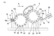
図2はロータ・コーミング機械2を示しており、ロータ・コーミング機械2は、送給ローラ10および送給トレイ11を備える供給デバイス8と、第1ローラ12(反転ロータ)と、第2ローラ13(コーミング・ロータ)と、取出しローラ14を備える取出しデバイス9と、周回するカード頂部コーミング・アセンブリ15とを有している。これらローラ10、12、13および14の回転方向は夫々、湾曲矢印10a、12a、13aおよび14aにより示される。到来する繊維ラップは参照番号16により表されると共に、吐出された繊維ウェブは参照番号17により表される。ローラ10、12、13および14は、相次いで配置される。矢印Aは動作方向を表している。
FIG. 2 shows a
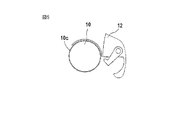
第1ローラ12、はその外周縁の領域において、複数個の第1挟持デバイス18(図3参照)を備えている。これら挟持デバイス18は、該ローラ12の幅に亙り延びていて各々が上側ニッパ19(把持要素)と下側ニッパ20(対向要素)とから構成されている。ローラ12の中心点もしくは枢動軸心を向く上記上側ニッパの一端領域において、各上側ニッパ19は、ローラ12に取付けられた枢動軸受24a(図11参照)に回転可能に取付けられている。下側ニッパ20は、固定されまたは移動可能とされ得るようにローラ12上に取付けられる(図11参照)。上側ニッパ19の自由端部は、ローラ12の周縁部に臨んでいる。上側ニッパ19および下側ニッパ20は、それらが繊維スライバ16、301、302を把持(挟持)し且つそれを解放する(図12(a)乃至図12(c)を参照)様に協働する。
The
第2ローラ13は、その外周縁の領域において、複数個の二部材式挟持デバイス21を備えている。二部材式挟持デバイス21(図3参照)は、第2ローラ13の幅に亙り延びていて各々が上側ニッパ22(把持要素)と下側ニッパ23(対向要素)とから構成されている。ローラ13の中心点もしくは枢動軸心を向く上記上側ニッパの一端領域において、各上側ニッパ22は、ローラ13に取付けられた枢動軸受24b(図11参照)に回転可能に取付けられる。下側ニッパ23は、固定され(図8参照)または移動可能(図1参照)とされ得るようにローラ13上に取付けられる。上側ニッパ22の自由端部は、ローラ13の周縁部に臨んでいる。上側ニッパ22および下側ニッパ23は、それらが繊維スライバ302、303を把持(挟持)し且つそれを解放する(図8;図10(a)、図10(b);図12(c)、図12(d))様に協働する。ローラ12の場合には、送給ローラ10と第2ローラ13との間におけるローラ周縁部の回りで各挟持デバイス18は閉じられ(それらは一端にて(不図示の)繊維束を挟持し)、且つ、第2ローラ13と送給ローラ10との間におけるローラ周縁部の回りで各挟持デバイス18は開かれる。ローラ13においては、第1ローラ12とドッファ14との間におけるローラ周縁部の回りで各挟持デバイス21は閉じられ(それらは一端にて(不図示の)繊維束を挟持し)、且つ、ドッファ14と第1ローラ12との間におけるローラ周縁部の回りで各挟持デバイス21は開かれる。参照番号50は、たとえばオートレベラ牽伸システムなどの牽伸システム50を表している。牽伸システム50は好適には、巻取器ヘッド3aの上方に配置される。参照番号51は、たとえばコンベア・ベルトなどの、駆動されて上昇するコンベア51を表している。搬送目的で、上方へと傾斜された板金などを使用してもよい。
The
図3に依れば2個の固定式カム・ディスク25および26が配備され、第1挟持デバイス18を有するローラ12と第2挟持デバイス21を有するローラ13とがカム・ディスクの回りにて、夫々、矢印12aおよび13aの方向に回転される。積載された上側ニッパ19および22は、カム・ディスク25、26の外周縁とローラ12、13の内側円筒状表面との間の中間スペース内に配置される。カム・ディスク25および26の回りにおけるローラ12および13の回転により、上側ニッパ19および22は枢動軸心24aおよび24bの回りで回転される。その様にして、第1挟持デバイス18および第2挟持デバイス21の開閉動作が実施される。
According to FIG. 3, two fixed
図4に依れば、送給ローラ10はその周縁部の回りに、上記幅に亙り軸心方向に平行に配置されたコーム・セグメント10bを有する。図5に依れば、送給ローラ10はその周縁部の回りに、針布10c、好適には全鋼針布を有する。図6(a)、図6(b)に依れば、上記供給デバイスは2本の無限回転ベルト27a、27bから成り、到来する繊維ラップ16のためのコンベア間隙がこれらベルト間に在る。図6(a)におけるコンベア間隙はローラ12に対して概ね径方向に配置され、図6(b)におけるコンベア間隙は回転方向12aに対向して配置される。図7(a)および図7(b)に依れば、(湾曲矢印を参照した回転方向に対して)送給ローラ対28a、28bと第1ローラ12との間には、頂部コーム291および292が夫々配置されている。頂部コーム291のコーム歯は上方から繊維ラップ16に係合し、且つ、頂部コーム292のコーム歯は下方から繊維ラップ16に係合する。
According to FIG. 4, the feeding
図8に依れば、幾つかの挟持デバイス21によって、各繊維束303はその一端にて、すなわちそれらの自由端部から所定距離にて、上側ニッパ22と下側ニッパ23との間で挟持される。その場合、繊維束303はそれらの自由端部の方向に屈曲され、該繊維束303の自由端部領域は各々、回転方向13aと逆方向に向けられる。周回する頂部コーミング・アセンブリ15は、2個の案内ローラ15aおよび15bの回りで無限に周回する可撓ベルト要素15cを備えており、可撓ベルト要素15cの外側部には、複数個のコーミング要素31を有するベルト要素15cが備えられている。コーミング要素31のコーム歯の自由端部はベルト要素15cから離間した方向を指している。コーミング要素31は、ローラ13の周縁部から所定距離における梳き取り領域に配置される。上記梳き取り領域においてベルト要素15cの運動方向15dおよびローラ13の運動方向13aは同一であり、すなわち同一方向動作が適用される。しかし、コーミング要素31を有するベルト要素15cの速度と、スライバ束303を含め挟持要素21を有するローラ13の速度とは異なり、すなわち、相対速度が適用される。上記作用領域(コーミング領域)におけるローラ13の円周速度は、コーミング要素31の運動の速度よりも大きい。
According to FIG. 8, by
図9に依れば上記コーミング要素は、ドッファ14とローラ12との間の領域(図2参照)においてローラ13に対向して該ローラ13の周囲部から所定距離に位置する複数個の回転コーミング・ローラ32により形成される。
According to FIG. 9, the combing element comprises a plurality of rotating combings which are positioned at a predetermined distance from the periphery of the
図10(a)に依れば、ローラ13およびドッファ14の回転方向13aおよび14aは同一(両方とも時計方向)である。結果として、逆方向の継ぎ合わせが実施される。コーミングされた繊維束304は、上記ドッファの円筒状表面上に屋根瓦の様式で相互に重ねて載置される。ドッファ14の内部においては、固定された篩要素33が在る。ドッファ14の円筒状表面は、空気透過性の開口を有する。ドッファ14と内側円筒状表面との間のスペースに負圧−pを掛けることにより、繊維束303はローラ13からドッファ14の外側円筒状表面上へと吸引される。篩要素33から外れたところで、すなわち負圧の無い領域においては、繊維束303はドッファ14の外側円筒状表面から取り外され得る。
According to FIG. 10A, the
図10(b)に依ると、ローラ13およびドッファ14の回転方向13aおよび14aは相互に逆である。結果として、同一方向の継ぎ合わせが実施される。コーミングされた繊維束303は、図10(a)に係る構成に関して記述されたのと実質的に同様にドッファ14によってローラ13から移動される。ドッファ14の下流にはスライバ・ファネル34が在り、スライバ・ファネル34内には、重なり合う繊維束304が進入して、これらの繊維束はコーミング済みスライバ35として出射しまたは引き出される。
According to FIG. 10B, the
図11に依れば上側ニッパ22は実質的に単一アーム式の回転可能レバーアームの形態である。このレバーアームは、該レバーアームの一端領域において枢動軸心24の回りで矢印BおよびCの方向に回転可能である。軸受36がローラ13に取付けられている。上側ニッパ22は、たとえば圧縮スプリングなどのスプリング37によって弾性的に付勢される。この弾性的な付勢作用は、カム・ディスク26と協働し、それにより、上側ニッパ22がスプリング37の圧縮力に抗してカム・ディスク26(図3参照)により偏向される様になる。下側ニッパ23はその一端の領域において例えば圧縮スプリングであるスプリング38により弾性的に付勢されることから、下側ニッパ23は矢印DおよびEの方向に移動可能である。その結果、上側ニッパ22を閉じる際に下側ニッパ23における圧力衝撃は弾性的に緩衝され、繊維束303の振動、摩耗および劣化は相当に減少されるようになる。参照番号40および41は固定軸受を表し、該軸受上にはスプリング37および38の各々の一端が支持される。
According to FIG. 11, the
第1挟持デバイス18の上側ニッパ19および下側ニッパ20は、第2挟持デバイス21について図11に示された様式に対応する様式で弾性的に付勢され得る。
The
図12(a)乃至図12(d)はロータ・コーミング機械2(ツー・ロータ式コーミング機械)の場合における繊維選択の動作シーケンスを概略形態で示しており、これら図面は相次ぐ時系列順にて以下の段階を示している:第1挟持デバイス18による、送給されたラップ16の挟持(図12(a))、第1ローラ12の回転方向12aにおける繊維タフト301の摘出(図12(b))、繊維タフト302が挟持されている上記挟持デバイスを開くことによるローラ12からローラ13への繊維タフト302の移送、および、コーミング要素31への推進係合による繊維タフト303のコーミング。
FIGS. 12 (a) to 12 (d) show the operation sequence of fiber selection in the case of the rotor combing machine 2 (two-rotor combing machine) in schematic form. shows the steps: by
図13に依れば、たとえばマイクロプロセッサを備えたマイクロコンピュータなどの電子的制御/調整デバイス42(機械およびシステムの制御手段)が配備されている。電子的制御/調整デバイス42には、特に、ロータ・コーミング機械2のローラ10、12、13、14、および、周回するカード頂部アセンブリ15(案内ローラ15a)のための電気モータなどの駆動デバイス43、44、45、46、47が接続されている。参照番号48は入力デバイス48を表し、参照番号49は表示デバイス49を表している。好適には、コーミング前処理機1、牽伸システム50、コンベア・ベルト51と、スライバ投入デバイス3とのための駆動デバイスも接続される(不図示)。
Referring to FIG. 13, an electronic control / regulation device 42 (machine and system control means) such as a microcomputer with a microprocessor is provided. The electronic control /
ローラ12および13が共通ギヤにより駆動される限りにおいて、該共通ギヤのための駆動モータは制御/調整デバイス42に接続される。
As long as the
たとえば、上記送給ローラに対する円周速度は約0.2〜1.0m/秒であり、第1ローラ12に対しては約2.0〜6.0m/秒、第2ローラ13に対しては約2.0〜6.0m/秒、上記ドッファに対しては約0.4〜1.5m/秒、および、上記周回するカード頂部アセンブリに対しては約1.5〜4.5m/秒である。第1ローラ12および第2ローラ13の直径は、たとえば約0.3m〜0.8mである。
For example, the circumferential speed with respect to the feed roller is about 0.2 to 1.0 m / sec, the
本発明に係る装置の動作モードおよび動作シーケンスは以下の通りである。 The operation mode and operation sequence of the apparatus according to the present invention are as follows.
ラップ調製:
複数本のスライバが組み合わされることでラップ16が形成され、一体的に牽伸される。複数枚のラップ16は、相互に重ねて載置されることで二重化され得る。結果的に形成されたラップ16は、ロータ・コーミング機械2の送給要素10内に直接的に導入される。材料の流れは、巻回ラップを形成することにより中断されることはない。
Wrap preparation:
A
送給:
フラット・コーミング機械と異なり、上流のラップ16はコンベア要素により連続的に送給される。送給される量は、第1ロータ12(旋回ロータ)のニッパ18(反転ニッパ)の2度の閉じ時点の間において搬送されるラップ16の長さにより決定される。
Supply:
Unlike flat combing machines, the
挟持1:
ラップ16から外方に突出していて整列された繊維タフトは、第1ロータ12(旋回ロータ)の挟持ニッパ18(反転ニッパ)により挟持される。第1ロータ12の挟持デバイス18は、摘出機能を前提とする。
Clamping 1:
The aligned fiber tufts protruding outward from the
摘出:
反転ニッパ18が配置された旋回ロータ12の回転の結果として、挟持された繊維タフトは送給されたラップから摘出されるが、反転ニッパ8により挟持されないラップ16における繊維は保持される様に、ラップ16に作用する保持力が必要とされる。上記保持力は、送給手段のコンベア要素により、または、送給トレイもしくは頂部コームの如き付加的手段により付与される。上記保持力を生成する上記要素は、頂部コームの機能を前提とする。
Extraction:
As a result of the rotation of the
挟持2:
繊維タフトは整列されると共に、第2ロータ13(コーミング・ロータ)の挟持デバイス21(コーミング・ニッパ)へと移送される。コーミング・デバイス21が閉じる時点における上記反転ニッパの挟持線と上記コーミング・ニッパの挟持線との間の距離により、上記隔たりが決定される。
Nipping 2:
The fiber tufts are aligned and transferred to the clamping device 21 (combing nipper) of the second rotor 13 (combing rotor). The distance is determined by the distance between the holding line of the inverted nipper and the holding line of the combing nipper when the combing
コーミング:
コーミング・ニッパ21から外方に突出する繊維タフトは、挟持されていない繊維であってコーミングにより排除される繊維を包含する。
Combing:
The fiber tuft protruding outward from the combing
継ぎ合わせ(Piecing):
梳き取り処理された繊維タフト303は、取出しローラ14上に載置される。吸引により作用されていて空気透過性である取出しローラ14の表面によって、繊維タフトは、取出しローラ14上に載置されて緊張延伸される。各繊維タフトは相互に重ねて載置され、屋根瓦のように重なり合い、繊維部分のウェブ304を形成する。
Piecing:
ウェブ取り外しおよびコーマ・スライバの形成:
ウェブ17は、吸引により影響されない取出しローラ14上の箇所において該取出しローラ14から取り外されると共に、ファネル34内へと案内される。
Web removal and formation of comba sliver:
The
コーマ・スライバ処置:
結果的に形成されたコーマ・スライバは二重化かつ牽伸されて(牽伸システム50)、次に、たとえば巻取器3aによりケンス3b内に投入される。
Comb sliver treatment:
The resulting comber sliver is doubled and drafted (drafting system 50) and then introduced into the
図14は、送給デバイス10、ローラ53およびドッファ・ローラ14を有するロータ・コーミング機械を示している。挟持デバイス19、20およびコーミング要素31は、ひとつの回転ローラの周縁部上に配置されている。
FIG. 14 shows a rotor combing machine having a
図8において参照番号は63は回転清浄化ローラを表し、該回転清浄化ローラは、梳き取られた繊維、ネップ(nep)、塵埃などの構成要素をコーミング要素31から解すと共に、それらを収集/抽出デバイス56へと推進させる。図9において各コーミング・ローラは同様に、抽出デバイス66を有する清浄化ローラ65を備えている。
In FIG. 8, the
本発明に係るロータ・コーミング機械2を用いると、たとえば3000〜5000ニップ/分などの、2000を超えるニップ/分が達成される。
With the
図15に依れば、挟持デバイス19、20および22、23を備えていて回転可能に取付けられたローラ12および13は、吸引チャネル52および56(吸引開口)を夫々付加的に備えている。供給デバイス8とローラ12との間における吐出領域およびローラ12および13の間における吐出領域において、吸引チャネル52、56は、搬送されつつある繊維の整列および移動に影響する。その様にして、供給デバイス8からの繊維材料を第1ローラ12上へと取り込むと共に第2ローラ13へと吐出するための時間は相当に減少され、それにより、ニップ速度は高められるようになる。吸引開口52、56はローラ12および13内に夫々配置されると共に、該ローラと共に回転する。各挟持デバイス19、20および22、23(ニッパ・デバイス)に対しては、少なくとも一個の吸引開口が関連付けられる。吸引開口52、56は各々、把持要素(上側ニッパ)と対向要素(下側ニッパ)との間に配置される。ロータ12、13の内部には、吸引開口52、56における吸引流により夫々生成された過小圧力領域53〜55および57〜59が在る。過小圧力は、流れ生成機に接続することにより生成され得る。個々の吸引開口52、56における吸引流は、該吸引流がローラ円周部上における特定の選択的角度位置においてのみ適用される様に、過小圧力領域と吸引開口との間において切換えられ得る。上記切換えの目的で、対応する角度位置において開口57および59を夫々備えたバルブもしくはバルブ管54、58が使用され得る。上記把持要素(上側ニッパ)の移動によって、吸引流の解除も達成され得る。更に、対応する角度位置においてのみ過小圧力の領域を配置できる。
According to FIG. 15, the
さらに、供給デバイス8の領域および/または各ローラ間の移送の領域においては、送風流が提供され得る。送風流の供給源(送風ノズル39)が送給ローラ10の内側に配置されると共に、該供給源は、上記供給デバイスの空気透過性表面または空気通路の開口を通じて、上記第1ローラの方向において外側に向かう効果を有する。さらに、供給デバイス8の領域において、送出される空気流を生成する上記要素は、該供給デバイス8の直下または直上において固定的に配置され得る。ローラ12、13間の移送の領域において、送出空気流源は、各ニッパ・デバイスの直下もしくは直上にて第1ローラ12の周縁部に配置され得る。送出空気を生成するために、圧縮空気ノズルまたは空気ブレードを使用してもよい。
Furthermore, in the area of the supply device 8 and / or in the area of transfer between the rollers, an air flow can be provided. A supply source of the blast flow (the blast nozzle 39) is arranged inside the
吸引流Bは好適には、案内だけでなく、供給デバイス8の領域において、ラップと、摘出されるべきタフトとの間の分離プロセスにも影響して、そのようなプロセスを短縮化し得る。 The suction flow B preferably affects not only the guidance but also the separation process between the wrap and the tuft to be extracted in the region of the supply device 8 and can shorten such a process.
付加的な空気案内要素60および側方篩61、62を配置した結果、上記流れの方向は影響され、各ロータにより回転して巻き込まれた空気が分離され得る。その様にして、設定に対する時間を更に短縮化できる。特に、ラップ上において第1ロータ12と供給デバイス8との間における篩要素、および、上記ローラの各側における篩要素は、有効であることが判明している。
As a result of the arrangement of the additional
梳き取り処理された繊維部分303は、第2ローラ13から継ぎ合わせローラ14上へと通過する。
本発明に係る上記ロータ・コーミング機械の使用に際しては、コーミングされるべき繊維材料の機械的コーミングが達成され、すなわち、コーミングのために機械的手段が用いられる。コーミングされるべき繊維材料の空気的コーミングは無く、すなわち、たとえば吸引および/または送出される空気流などの空気流は使用されない。 In the use of the rotor combing machine according to the invention, mechanical combing of the fiber material to be combed is achieved, i.e. mechanical means are used for combing. There is no pneumatic combing of the fiber material to be combed, i.e. no air flow is used, e.g. aspirated and / or delivered air flow.
本発明に係る上記ロータ・コーミング機械においては、中断されることなしに迅速に回転するローラであって挟持デバイスを有するというローラが存在する。中断を以て回転するローラ、段階的に回転するローラ、または、静止状態と回転状態との間において交互的に回転するローラは使用されない。 In the above-described rotor combing machine according to the present invention, there is a roller that has a clamping device that rotates rapidly without interruption. A roller that rotates with interruption, a roller that rotates stepwise, or a roller that rotates alternately between a stationary state and a rotating state is not used.
1 コーミング前処理機
2、21〜27 ロータ・コーミング機械
3 スライバ投入デバイス
3a 巻取器
3b ケンス
4a、4b 送給テーブル
5a、5b 繊維スライバ用ケンス
6a、6b 牽伸システム
7 テーブル
8 供給デバイス
9 取出しデバイス
10 送給ローラ
12、13 ローラ
11 送給トレイ
15 頂部コーミング・アセンブリ
16、161〜167 繊維ラップ
18、19、20、21 挟持デバイス
22 上側ニッパ
23 下側ニッパ
27a、27b 無限回転ベルト
28a、28b 送給ローラ対
301〜304 繊維スライバ
31 コーミング要素
32 ローラ
33 篩要素
34 ファネル
42 電子的制御/調整デバイス
50 牽伸システム
51 コンベア
52 吸引チャネル
53〜55、57〜59 過小圧力領域
54、58 バルブ管
65 清浄化ローラ
66 抽出デバイス
DESCRIPTION OF SYMBOLS 1 Combing
Claims (23)
回転可能に取付けられた少なくとも一個のローラ(12、13)が上記供給手段(8;10、11、27a、27b、28a、28b)の下流に配置されており、該ローラは、該ローラ(12、13)の周縁部の領域において離間して分布された上記繊維スライバ(16;301〜303)用挟持デバイス(18、19、20;21、22、23)を備えており、
コーミング作用を生成する上記生成手段(15、31、32)は上記ローラ(13)に関係付けられており、前記回転可能に取付けられた少なくとも一個のローラ(12、13)は中断されることなしに迅速に連続的に回転することを特徴とする、装置。 An apparatus for classifying or selecting a fiber sliver composed of woven fibers supplied by a supply means to a fiber classification device, the apparatus separating the fiber sliver at a predetermined distance from a free end of the fiber sliver. A mechanical generating means for generating a combing action from a clamping part to the free end in order to remove a non-clamping component from the free end of the fiber sliver, wherein a clamping device is provided for clamping In the device that exists,
At least one roller (12, 13), which is rotatably mounted, is arranged downstream of the supply means (8; 10, 11, 27a, 27b, 28a, 28b), and the roller (12 And 13) the fiber sliver (16; 30 1 to 30 3 ) clamping devices (18, 19, 20; 21, 22, 23) distributed in the peripheral region,
The generating means (15, 31, 32) for generating the combing action are associated with the roller (13), and the at least one roller (12, 13) mounted rotatably is not interrupted. A device characterized in that it rotates rapidly and continuously .
Applications Claiming Priority (6)
| Application Number | Priority Date | Filing Date | Title |
|---|---|---|---|
| DE102006050384.8 | 2006-10-20 | ||
| DE102006050384 | 2006-10-20 | ||
| DE202007010686 | 2007-06-29 | ||
| DE202007010686.6 | 2007-06-29 | ||
| DE102007037426.9 | 2007-08-08 | ||
| DE102007037426A DE102007037426A1 (en) | 2006-10-20 | 2007-08-08 | Device for fiber sorting or selection of a fiber structure of textile fibers, in particular for combing |
Publications (3)
| Publication Number | Publication Date |
|---|---|
| JP2008101319A JP2008101319A (en) | 2008-05-01 |
| JP2008101319A5 JP2008101319A5 (en) | 2010-10-14 |
| JP5275609B2 true JP5275609B2 (en) | 2013-08-28 |
Family
ID=38814058
Family Applications (1)
| Application Number | Title | Priority Date | Filing Date |
|---|---|---|---|
| JP2007272855A Expired - Fee Related JP5275609B2 (en) | 2006-10-20 | 2007-10-19 | A device for selecting and classifying fiber sliver made of woven fiber, especially for fiber classification or fiber selection |
Country Status (9)
| Country | Link |
|---|---|
| US (1) | US20080092339A1 (en) |
| JP (1) | JP5275609B2 (en) |
| CN (1) | CN101165239B (en) |
| BR (1) | BRPI0704414A (en) |
| CH (1) | CH701944B1 (en) |
| DE (1) | DE102007037426A1 (en) |
| FR (1) | FR2909689B3 (en) |
| GB (1) | GB0720395D0 (en) |
| IT (1) | ITMI20071845A1 (en) |
Families Citing this family (12)
| Publication number | Priority date | Publication date | Assignee | Title |
|---|---|---|---|---|
| CH703441B1 (en) * | 2007-06-29 | 2012-01-31 | Truetzschler Gmbh & Co Kg | Apparatus for sorting and selection of fibers of a fiber strand of textile fibers. |
| CH703154B1 (en) * | 2007-06-29 | 2011-11-30 | Truetzschler Gmbh & Co Kg | Device for fiber sorting and -selection of a fiber structure made of textile fibers. |
| GB0811191D0 (en) * | 2007-06-29 | 2008-07-23 | Truetzschler Gmbh & Co Kg | Apparatus for the fibre-sorting or fibre-selection of a fibre bundle comprising textille fibre, especially for combing |
| ITMI20081097A1 (en) * | 2007-06-29 | 2008-12-30 | Truetzschler Gmbh & Co Kg | EQUIPMENT FOR THE FIBER SORTING OR THE FIBER SELECTION OF A FIBER BAND INCLUDING TEXTILE FIBERS, ESPECIALLY FOR COMBING |
| GB0811207D0 (en) * | 2007-06-29 | 2008-07-23 | Truetzschler Gmbh & Co Kg | Apparatus for the fibre-sorting or fibre-selection of a fibre bundle comprising textile fibres, especially for combing |
| CH703786B1 (en) * | 2007-06-29 | 2012-03-30 | Truetzschler Gmbh & Co Kg | Device for fiber sorting and -selection of a fiber structure made of textile fibers. |
| DE102008004098A1 (en) * | 2007-06-29 | 2009-01-02 | TRüTZSCHLER GMBH & CO. KG | Device for fiber sorting or selection of a fiber structure of textile fibers, in particular for combing, which is fed via feeding means of a fiber sorting device, in particular combing device |
| US7823257B2 (en) * | 2007-06-29 | 2010-11-02 | Fa. Trützschler GmbH & Co. KG | Apparatus for the fibre-sorting or fibre-selection of a fibre bundle comprising textile fibres, especially for combing |
| CN102776605B (en) * | 2012-07-31 | 2014-12-10 | 上海一纺机械有限公司 | Combing head structure of combing machine |
| CN107177908B (en) * | 2017-06-20 | 2019-07-23 | 东华大学 | A kind of air draught lace curtaining device and its working method applied to carding machine |
| CN109913983A (en) * | 2019-04-03 | 2019-06-21 | 合肥岸鲁意科技有限公司 | A kind of pure cotton combed woven yarn high-efficiency method for producing |
| CN114959961B (en) * | 2022-04-20 | 2023-08-25 | 微山鑫盛纺织有限公司 | Blended yarn processing device |
Family Cites Families (10)
| Publication number | Priority date | Publication date | Assignee | Title |
|---|---|---|---|---|
| US1408780A (en) * | 1918-08-06 | 1922-03-07 | Schleifer Riccardo | Process and machine for combing textile fibers |
| GB246499A (en) * | 1925-01-24 | 1926-07-15 | Charles Gegauff | Improvements in the art of carding cotton or like fibres |
| JPS511725A (en) * | 1974-06-25 | 1976-01-08 | Mitsubishi Heavy Ind Ltd | KOOMA |
| US5131117A (en) * | 1989-02-22 | 1992-07-21 | Pettinatura Europa S.R.L. | Straight combing machine for wool and a combing method |
| EP0450409A1 (en) * | 1990-04-05 | 1991-10-09 | Maschinenfabrik Rieter Ag | Combing machine |
| GB9116083D0 (en) * | 1991-07-25 | 1991-09-11 | Carding Spec Canada | Carding machine |
| CH685301A5 (en) * | 1992-04-03 | 1995-05-31 | Rieter Ag Maschf | Comber. |
| JP2002180335A (en) * | 2000-12-11 | 2002-06-26 | Truetzschler Gmbh & Co Kg | Apparatus installed in card |
| DE10139163B4 (en) * | 2001-08-09 | 2014-11-13 | Trützschler GmbH & Co Kommanditgesellschaft | Device on a card in which the clothing of the drum opposite cover elements are present |
| DE10207159B4 (en) * | 2002-02-20 | 2015-12-17 | Trützschler GmbH & Co Kommanditgesellschaft | Device on a card in which a roller, z. B. drum, a plurality of working elements is assigned |
-
2007
- 2007-08-08 DE DE102007037426A patent/DE102007037426A1/en not_active Withdrawn
- 2007-09-25 IT IT001845A patent/ITMI20071845A1/en unknown
- 2007-10-16 CN CN2007101802531A patent/CN101165239B/en not_active Expired - Fee Related
- 2007-10-17 GB GBGB0720395.3A patent/GB0720395D0/en not_active Ceased
- 2007-10-18 FR FR0758408A patent/FR2909689B3/en not_active Expired - Lifetime
- 2007-10-19 JP JP2007272855A patent/JP5275609B2/en not_active Expired - Fee Related
- 2007-10-19 BR BRPI0704414-3A patent/BRPI0704414A/en not_active IP Right Cessation
- 2007-10-19 CH CH01631/07A patent/CH701944B1/en not_active IP Right Cessation
- 2007-10-22 US US11/976,155 patent/US20080092339A1/en not_active Abandoned
Also Published As
| Publication number | Publication date |
|---|---|
| CH701944B1 (en) | 2011-04-15 |
| ITMI20071845A1 (en) | 2008-04-21 |
| JP2008101319A (en) | 2008-05-01 |
| US20080092339A1 (en) | 2008-04-24 |
| FR2909689A1 (en) | 2008-06-13 |
| CN101165239B (en) | 2011-06-08 |
| CN101165239A (en) | 2008-04-23 |
| DE102007037426A1 (en) | 2008-04-24 |
| GB0720395D0 (en) | 2007-11-28 |
| FR2909689B3 (en) | 2009-03-06 |
| BRPI0704414A (en) | 2008-06-10 |
Similar Documents
| Publication | Publication Date | Title |
|---|---|---|
| JP5275609B2 (en) | A device for selecting and classifying fiber sliver made of woven fiber, especially for fiber classification or fiber selection | |
| JP5350689B2 (en) | Apparatus for fiber sorting or fiber selection, in particular combing, of fiber bundles comprising textile fibers fed to a fiber sorting device by a feeding device, in particular to a combing device | |
| JP5280751B2 (en) | Apparatus for classifying or selecting fiber bundles with textile fibers, especially for combing | |
| JP5290644B2 (en) | Equipment for fiber classification or fiber selection for combing | |
| JP5270235B2 (en) | Apparatus for classifying or selecting a fiber bundle composed of woven fibers supplied by a supply means to a fiber classification device, in particular a combing device, in particular for combing. | |
| JP5479692B2 (en) | Equipment for sorting or selecting fibers for combing fiber bundles | |
| JP5290641B2 (en) | Equipment for classifying or selecting fiber bundles made of textile fibers, especially for combing | |
| US20090000071A1 (en) | Apparatus for the fibre-sorting or fibre-selection of a fibre bundle comprising textile fibres, especially for combing | |
| JP5074149B2 (en) | Apparatus for sorting or selecting fiber sliver made of textile fibers, in particular combing and having a feeding device |
Legal Events
| Date | Code | Title | Description |
|---|---|---|---|
| A521 | Request for written amendment filed |
Free format text: JAPANESE INTERMEDIATE CODE: A523 Effective date: 20100831 |
|
| A621 | Written request for application examination |
Free format text: JAPANESE INTERMEDIATE CODE: A621 Effective date: 20100831 |
|
| A977 | Report on retrieval |
Free format text: JAPANESE INTERMEDIATE CODE: A971007 Effective date: 20120209 |
|
| A131 | Notification of reasons for refusal |
Free format text: JAPANESE INTERMEDIATE CODE: A131 Effective date: 20120221 |
|
| A521 | Request for written amendment filed |
Free format text: JAPANESE INTERMEDIATE CODE: A523 Effective date: 20120315 |
|
| A131 | Notification of reasons for refusal |
Free format text: JAPANESE INTERMEDIATE CODE: A131 Effective date: 20120724 |
|
| A521 | Request for written amendment filed |
Free format text: JAPANESE INTERMEDIATE CODE: A523 Effective date: 20120813 |
|
| A131 | Notification of reasons for refusal |
Free format text: JAPANESE INTERMEDIATE CODE: A131 Effective date: 20130129 |
|
| A521 | Request for written amendment filed |
Free format text: JAPANESE INTERMEDIATE CODE: A523 Effective date: 20130328 |
|
| TRDD | Decision of grant or rejection written | ||
| A01 | Written decision to grant a patent or to grant a registration (utility model) |
Free format text: JAPANESE INTERMEDIATE CODE: A01 Effective date: 20130416 |
|
| A61 | First payment of annual fees (during grant procedure) |
Free format text: JAPANESE INTERMEDIATE CODE: A61 Effective date: 20130516 |
|
| R150 | Certificate of patent or registration of utility model |
Free format text: JAPANESE INTERMEDIATE CODE: R150 |
|
| R250 | Receipt of annual fees |
Free format text: JAPANESE INTERMEDIATE CODE: R250 |
|
| R250 | Receipt of annual fees |
Free format text: JAPANESE INTERMEDIATE CODE: R250 |
|
| LAPS | Cancellation because of no payment of annual fees |