JP5290641B2 - Equipment for classifying or selecting fiber bundles made of textile fibers, especially for combing - Google Patents
Equipment for classifying or selecting fiber bundles made of textile fibers, especially for combing Download PDFInfo
- Publication number
- JP5290641B2 JP5290641B2 JP2008168529A JP2008168529A JP5290641B2 JP 5290641 B2 JP5290641 B2 JP 5290641B2 JP 2008168529 A JP2008168529 A JP 2008168529A JP 2008168529 A JP2008168529 A JP 2008168529A JP 5290641 B2 JP5290641 B2 JP 5290641B2
- Authority
- JP
- Japan
- Prior art keywords
- roller
- fiber
- splicing
- combing
- fiber bundle
- Prior art date
- Legal status (The legal status is an assumption and is not a legal conclusion. Google has not performed a legal analysis and makes no representation as to the accuracy of the status listed.)
- Expired - Fee Related
Links
Images


Classifications
-
- D—TEXTILES; PAPER
- D01—NATURAL OR MAN-MADE THREADS OR FIBRES; SPINNING
- D01G—PRELIMINARY TREATMENT OF FIBRES, e.g. FOR SPINNING
- D01G19/00—Combing machines
- D01G19/06—Details
- D01G19/08—Feeding apparatus
-
- D—TEXTILES; PAPER
- D01—NATURAL OR MAN-MADE THREADS OR FIBRES; SPINNING
- D01G—PRELIMINARY TREATMENT OF FIBRES, e.g. FOR SPINNING
- D01G19/00—Combing machines
- D01G19/06—Details
- D01G19/14—Drawing-off and delivery apparatus
- D01G19/16—Nipper mechanisms
Landscapes
- Engineering & Computer Science (AREA)
- Textile Engineering (AREA)
- Preliminary Treatment Of Fibers (AREA)
Description
本発明は、特にコーミング・デバイスである繊維分類デバイスに対して供給手段により供給された織物繊維から成る繊維束を特にコーミングのために繊維分類もしくは繊維選択する装置であって、繊維束の自由端部から所定距離にて該繊維束を挟持する挟持デバイスが配備され、上記繊維束の上記挟持部位から上記自由端部にかけてコーミング作用を生成する機械的手段が存在し、コーミングされた繊維材料を取り外すための周回手段が存在し、該周回手段はその周縁部上に空気透過性開口を備えると共に、その内側空間の少なくともひとつの下位領域は負圧源に接続されるという装置に関する。 The invention relates to a device for classifying or selecting a fiber bundle composed of woven fibers supplied by a supply means to a fiber sorting device, in particular a combing device, especially for combing, the free end of the fiber bundle A holding device is provided for holding the fiber bundle at a predetermined distance from the section, and there is a mechanical means for generating a combing action from the holding portion of the fiber bundle to the free end, and the combed fiber material is removed. There is an orbiting means for the device, the encircling means comprising an air permeable opening on its peripheral edge and at least one subregion of its inner space connected to a negative pressure source.
実際問題としてコーミング機械は、綿繊維または羊毛繊維に含まれる天然の夾雑物を遊離させるべく、且つ、繊維スライバの繊維を平行化すべく使用される。その目的のために、"繊維タフト"として知られる繊維の一定の短寸部分がニッパ機構の把持部の前方に突出する様に、事前準備された繊維束が把持部同士の間に挟持される。回転するコーミング・ローラのコーミング・セグメントであってニードル針布または歯付き針布により満たされたコーミング・セグメントにより、この繊維タフトはコーミングされることで清浄化される。取出しデバイスは通常は逆回転する2個のローラから成り、これらのローラは、コーミングされた繊維タフトを把持して該タフトを前方へと搬送する。公知の綿コーミング・プロセスは不連続プロセスである。ニップ動作の間において、全てのアセンブリおよびそれらの駆動手段およびギヤは、加速、減速され、および、一定の場合には再び反転される。大きなニップ速度は、大きな加速に帰着する。特に、各ニッパの運動、ニッパ移動のためのギヤの運動、剥ぎ取りローラの前後回転のためのギヤの運動の結果として、大きな加速力が引き起こされる。引き起こされる力および応力は、ニップ速度が大きいほど大きくなる。公知のフラット・コーミング機械はそのニップ速度により性能限界に達し、生産性の増大が妨げられている。更に、不連続な動作様式によれば機械全体における振動が引き起こされ、動的で交互的な応力が生成される。 In practice, combing machines are used to release natural contaminants contained in cotton or wool fibers and to parallelize the fibers of the fiber sliver. For that purpose, a pre-prepared fiber bundle is sandwiched between the gripping parts so that a certain short part of the fiber known as "fiber tuft" projects forward of the gripping part of the nipper mechanism . The fiber tuft is combed and cleaned by a combing segment of a rotating combing roller, which is filled with a needle cloth or a toothed cloth. The take-out device usually consists of two counter-rotating rollers that grip the combed fiber tuft and carry it forward. The known cotton combing process is a discontinuous process. During the nip operation, all assemblies and their drive means and gears are accelerated, decelerated and, in certain cases, reversed again. A large nip speed results in a large acceleration. In particular, a large acceleration force is caused as a result of the movement of each nipper, the movement of the gear for nipper movement, and the movement of the gear for the longitudinal rotation of the peeling roller. The forces and stresses that are caused increase as the nip speed increases. Known flat combing machines reach their performance limit due to their nip speed, which hinders productivity gains. Furthermore, the discontinuous mode of operation causes vibrations throughout the machine, generating dynamic and alternating stresses.
WO2006/012758Aはコーミング機械を開示しており、その場合に2個の剥ぎ取りローラにより剥ぎ取られた繊維束は、空気流の影響下にて下流の有孔ドラムに対して不連続的に供給されると共に、すでに形成された繊維ウェブに対して加えられる(継ぎ合わせ)。上記剥ぎ取りローラにより搬送された繊維ウェブの前端部は、このプロセスにおいては、上記有孔ドラムに向けて押し進められる。上記有孔ドラムは、時計方向回転も行う。上記有孔ドラムの内側には2個の開口を備えた回転可能シリンダが配置され、これらの開口は該シリンダの回転運動と協働して、繊維束の前端部が上記有孔ドラムの回転方向に偏向される一方で、該繊維束の後端部は上記剥ぎ取りローラが該繊維束を解放した後で上記有孔ドラム上に載置されることを確実とする。その不都合は、設備に関する多額の経費である。特に、大きな生産量が可能でないことは不都合である。繊維束を搬送する上記剥ぎ取りローラの回転速度は、上流の低速のコーミング・プロセスに対して適合化され、これにより制限される。更なる不利益は、各繊維束が、上記剥ぎ取りローラ対により、挟持され且つ搬送されることである。挟持点は上記剥ぎ取りローラの回転の故に定常的に変化し、すなわち、挟持を行う上記ローラと繊維束との間には定常的な相対運動が在る。全ての繊維束は、剥ぎ取りローラ対を連続して通過すべきであり、このことは、製造速度に関して更に相当の制限を呈する。 WO2006 / 012758A discloses a combing machine, in which case the fiber bundles stripped by two stripping rollers are supplied discontinuously to the downstream perforated drum under the influence of air flow And added to the already formed fibrous web (seaming). In this process, the front end portion of the fiber web conveyed by the peeling roller is pushed toward the perforated drum. The perforated drum also rotates clockwise. A rotatable cylinder having two openings is disposed inside the perforated drum, and these openings cooperate with the rotational movement of the cylinder so that the front end portion of the fiber bundle is in the rotational direction of the perforated drum. While the rear end of the fiber bundle ensures that the stripping roller rests on the perforated drum after releasing the fiber bundle. The disadvantage is the large expense associated with the equipment. In particular, it is inconvenient that a large production volume is not possible. The rotational speed of the stripping roller carrying the fiber bundle is adapted and limited by the upstream low speed combing process. A further disadvantage is that each fiber bundle is pinched and transported by the pair of stripping rollers. The pinching point changes constantly due to the rotation of the stripping roller, that is, there is a steady relative motion between the roller that performs the pinching and the fiber bundle. All fiber bundles should pass through the pair of stripping rollers in succession, which presents a further considerable limitation on the production speed.
故に、本発明の基礎となる課題は、冒頭部にて記述された種類の装置であって、言及された不都合を解消すると共に、特に簡素な手法で、時間当たりに生産される量(生産性)を相当に増大し得ると共に、更に大きな製造速度にて確実な取出しおよび継ぎ合わせを可能とする装置を提供するに在る。 The problem underlying the present invention is therefore an apparatus of the kind described at the outset, which eliminates the disadvantages mentioned and produces a quantity (productivity per hour) produced in a particularly simple manner. ) Can be significantly increased, and an apparatus is provided that allows reliable removal and splicing at higher production rates.
この課題は、請求項1の特徴部分の特徴により解決される。
すなわち1番目の発明によれば、繊維分類デバイスに対して供給手段により供給された織物繊維から成る繊維束を繊維分類もしくは繊維選択する装置であって、繊維束の自由端部から所定距離にて該繊維束を挟持する挟持デバイスが配備され、上記繊維束の上記挟持部位から上記自由端部にかけてコーミング作用を生成する機械的手段が存在し、コーミングされた繊維材料を取り外すために継ぎ合わせ要素である周回手段が存在し、該周回手段はその周縁部上に空気透過性開口を備えると共に、その内側空間の少なくともひとつの下位領域は減圧源に対して接続されるという装置において、上記供給手段(8;10、11)の下流には、回転されて搬送される繊維束(16;30 1 〜30 3 )のための挟持デバイス(18、19;21、22、23)を備えると共に回転可能に取付けられて中断なしで回転する少なくとも2つのローラ(12;13)が配置され、上記挟持デバイスは、上記ローラの周縁部の領域において離間されて分布され、且つ、コーミング作用を生成する手段(コーミング要素)が少なくとも一方の上記ローラ(13)に組み合わされ、周回手段(14)によるコーミング済み繊維束(30 3 )の自由領域(30I)の取り込みの後で、上記コーミング済み繊維束(30 3 )の挟持端(30II)の挟持は解除可能であり、継ぎ合わせローラに対しては、コーミング・セグメントによりコーミングされた繊維タフトが供給可能であり、前記繊維束が前記継ぎ合わせローラにより取り込まれると共に、挟持が終結する後まで、挟持要素と上記繊維束との間の相対運動は開始しないことを特徴とする、装置が提供される。
This problem is solved by the features of the characterizing portion of
That is, according to the first aspect of the invention, there is provided an apparatus for classifying or selecting a fiber bundle composed of woven fibers supplied to the fiber classification device by the supply means, at a predetermined distance from the free end of the fiber bundle. A clamping device is provided for clamping the fiber bundle, and there is a mechanical means for generating a combing action from the clamping site of the fiber bundle to the free end, and a seaming element for removing the combed fiber material In the apparatus in which there is a surrounding means, the surrounding means is provided with an air-permeable opening on the peripheral edge thereof, and at least one sub-region of the inner space is connected to a decompression source, the supply means ( 8; 10, 11) Downstream of the fiber bundles (16; 30 1 to 30 3 ) to be conveyed by being rotated and provided with a clamping device (18, 19; 21, 22, 23) Mounting At least two rollers (12; 13) that are rotated without interruption, the clamping device being distributed in the region of the peripheral edge of the roller and means for generating a combing action (combing element ) Is combined with at least one of the rollers (13), and after taking in the free region (30I) of the combed fiber bundle (30 3 ) by the rotating means (14), the combed fiber bundle (30 3 ) The pinching of the pinching end (30II) can be released, and the fiber tuft combed by the combing segment can be supplied to the splicing roller, and the fiber bundle is taken in by the splicing roller and is pinched. A device is provided, characterized in that the relative movement between the clamping element and the fiber bundle does not start until after the end .
梳き取り処理されるべき繊維束を挟持して移動させる機能を複数の回転ローラ上で実現することにより、公知の装置と異なり、大きな質量の加速および反転運動なしで、大きな運転速度(ニップ速度)が達成される。特に、動作の様式は連続的である。高速のローラが使用されたときには時間当たりの製造速度(生産性)が相当に高められるが、これは、従前の技術範囲では可能とは思われていなかった。更なる利点は、複数の挟持デバイスを備えた上記ローラの回転的な回転運動の結果、複数個の繊維束が単位時間当たりに取出しローラに対して異例な速さを以て供給されるということである。特に上記各ローラの大きな回転速度によれば、生産量が相当に増大され得る。繊維束を形成するために、送給ローラにより前方に押し出された繊維スライバは、一端にて挟持デバイスにより挟持され、旋回ロータの回転運動により剥ぎ取られる。挟持された端部は短繊維を含み、自由領域は長繊維から成る。長繊維は送給ニップにおいて挟持された繊維材料から分離力により引き出され、短繊維は、上記送給ニップにおける保持力により後に残る。引き続き、繊維束が旋回ロータからコーミング・ロータ上へと移行されるときに繊維束の各端部は反転され、上記コーミング・ロータ上の挟持デバイスは長繊維の端部を把持して挟持することから、短繊維を備えた領域は上記挟持デバイスから突出し且つ露出して位置することにより、梳き取り処理され得る。 Unlike a known device, it realizes the function of holding and moving the fiber bundle to be scraped off on a plurality of rotating rollers, so that a large operating speed (nip speed) can be achieved without large mass acceleration and reversal motion. Is achieved. In particular, the mode of operation is continuous. When high speed rollers are used, the production rate per hour (productivity) is considerably increased, but this was not considered possible in the prior art. A further advantage is that as a result of the rotational rotation of the roller with a plurality of clamping devices, a plurality of fiber bundles are fed to the take-out roller at an unusual speed per unit time. . In particular, due to the large rotational speed of the rollers, the production volume can be increased considerably. In order to form a fiber bundle, the fiber sliver pushed forward by the feeding roller is pinched by a pinching device at one end, and is peeled off by the rotational motion of the swivel rotor. The sandwiched end contains short fibers and the free region consists of long fibers. Long fibers are pulled out by the separating force from the fiber material sandwiched in the feeding nip, and the short fibers are left behind by the holding force in the feeding nip. Subsequently, each end of the fiber bundle is inverted when the fiber bundle is transferred from the swirling rotor onto the combing rotor, and the clamping device on the combing rotor grips and holds the end of the long fiber. Thus, the region with short fibers can be scraped off by projecting from the clamping device and being located exposed.
公知の装置と異なり、上記繊維束は、複数の挟持デバイスにより保持され且つ回転下で搬送される。故に特定の挟持デバイスにおける挟持点は、各繊維束が上記取出しローラへと移行されるまで、一定のままである。また、挟持デバイスと繊維束との間の相対運動は、繊維束が取出しローラ(継ぎ合わせローラ)により把持されてから更に挟持が解除される後まで、開始しない。各繊維束に対して複数の挟持デバイスが夫々利用可能であることから、まさに単一の供給デバイスから帰着する不都合な時間遅延なしで、特に好適な様式で、繊維束は相次いで迅速に連続して継ぎ合わせローラに供給され得る。 Unlike known devices, the fiber bundle is held by a plurality of clamping devices and conveyed under rotation. Therefore, the pinching point in a specific pinching device remains constant until each fiber bundle is transferred to the take-out roller. In addition, the relative movement between the clamping device and the fiber bundle does not start until after the fiber bundle is gripped by the take-out roller (joining roller) and after the clamping is further released. Since a plurality of clamping devices are available for each fiber bundle, the fiber bundles are successively connected one after another in a particularly suitable manner without the inconvenient time delay resulting from just a single feeding device. Can be supplied to the splicing roller.
請求項2乃至31は、本発明の好適な発展例を包含する。
2番目の発明によれば、1番目の発明において、前記周回手段は回転可能な取出しローラである。
3番目の発明によれば、2番目の発明において、前記取出しローラの円筒状表面は空気通路開口を有する。
4番目の発明によれば、1番目の発明において、前記挟持デバイスを備えた前記ローラの回転速度を制御する手段が配備される。
5番目の発明によれば、1番目の発明において、前記ローラの前記挟持デバイスからの繊維束の吐出、および、前記取出しローラ上への繊維束の取り込みは同期される。
6番目の発明によれば、1番目の発明において、前記繊維タフトが前記継ぎ合わせローラに対して供給されるとき、前記挟持部位に向けて該ローラが移動するときに上記繊維タフトは固定位置に在る。
7番目の発明によれば、1番目の発明において、挟持された繊維タフトはロータ軸心の回りにおいて前記材料の回転方向に回転して移動可能である。
8番目の発明によれば、1番目の発明において、前記繊維束に対する挟持力の終結の時点は調節可能である。
9番目の発明によれば、8番目の発明において、前記繊維束の挟持力の終結の時点を経て、前記継ぎ合わせローラ上への載置時における上記繊維束の引張り牽伸は調節可能である。
10番目の発明によれば、2番目の発明において、前記取出しローラの円筒状表面は空気通路開口を含む。
11番目の発明によれば、1番目の発明において、前記継ぎ合わせローラは減圧源に接続される。
12番目の発明によれば、1番目の発明において、コーミングされた各繊維束は前記継ぎ合わせローラ上で重なり合う。
13番目の発明によれば、12番目の発明において、重なり合い長さは前記継ぎ合わせローラとコーミング・ロータとの間の相対速度に応じて調節可能である。
14番目の発明によれば、13番目の発明において、前記重なり合い長さを変更することによりウェブ重量および均一性(CV)が変更可能である。
15番目の発明によれば、1番目の発明において、同一方向の継ぎ合わせと逆方向の継ぎ合わせとの間における変更により、繊維掛止方向を繊維の前端掛止または後端掛止に変更され得る。
16番目の発明によれば、1番目の発明において、前記継ぎ合わせローラの内周表面の一部分は篩要素によりシール可能である。
17番目の発明によれば、1番目の発明において、前記継ぎ合わせローラと少なくとも一つのウェブ堅固化要素が協働する。
18番目の発明によれば、12番目の発明において、前記ウェブ堅固化要素は、前記コーミング・ロータから前記継ぎ合わせローラ上への移行箇所と、上記継ぎ合わせローラから前記材料が降荷される箇所への該継ぎ合わせローラからの移行箇所との間に位置される。
19番目の発明によれば、12番目の発明において、複数個のウェブ堅固化要素を使用するとき、前記継ぎ合わせローラに関する各要素間の間隔は前記材料の流れ方向において連続的に小さくなる。
20番目の発明によれば、12番目の発明において、少なくともひとつのウェブ堅固化要素は回転可能な圧力付与ローラまたは周回ベルトである。
21番目の発明によれば、12番目の発明において、前記少なくともひとつのウェブ堅固化要素の表面上には針布が配置される。
22番目の発明によれば、1番目の発明において、前記継ぎ合わせローラの前記外側円筒状表面は、カバー要素またはケーシングを備える。
23番目の発明によれば、22番目の発明において、前記カバー要素またはケーシングは、必要とされる空気の体積を減少するために減圧領域に位置される。
24番目の発明によれば、22番目の発明において、前記カバー要素またはケーシング、もしくは、該ケーシングの一部分は静電防止構成である。
25番目の発明によれば、1番目の発明において、前記継ぎ合わせローラの外側円筒状表面には空気案内開口が配備される。
26番目の発明によれば、25番目の発明において、前記空気案内要素は、コーミング・ロータと継ぎ合わせローラとの間のニップ領域に取付けられる。
27番目の発明によれば、25番目の発明において、前記空気案内要素は前記継ぎ合わせローラの周縁部に関し、該継ぎ合わせローラからの前記繊維材料の取り外しの箇所に配置される。
28番目の発明によれば、1番目の発明において、前記空気案内要素は前記カバー要素と前記継ぎ合わせローラとの間に取付けられる。
29番目の発明によれば、1番目の発明において、前記継ぎ合わせローラを含むコンベア・ベルトの幾何学的構成に依存して、繊維の取り外し領域は、継ぎ合わせローラを使用するときよりも、前記コーミング・ロータに更に接近して位置される。
30番目の発明によれば、1番目の発明において、コンベア・ベルトの幾何学的構成に依存して、前記コーミング・ロータと、継ぎ合わせローラとして使用される該コンベア・ベルトとの間には、比較的に長寸の移行領域が存在する。
31番目の発明によれば、1番目の発明において、ロータの周縁部に位置された2つのベルト案内ローラが存在する。
According to a second aspect, in the first aspect, the rotating means is a rotatable take-out roller.
According to a third aspect, in the second aspect, the cylindrical surface of the take-out roller has an air passage opening.
According to a fourth aspect, in the first aspect, means for controlling the rotational speed of the roller provided with the clamping device is provided.
According to the fifth aspect, in the first aspect, the ejection of the fiber bundle from the clamping device of the roller and the taking-in of the fiber bundle onto the take-out roller are synchronized.
According to a sixth aspect, in the first aspect, when the fiber tuft is supplied to the splicing roller, the fiber tuft is in a fixed position when the roller moves toward the clamping portion. exist.
According to the seventh aspect, in the first aspect, the sandwiched fiber tuft is movable in the direction of rotation of the material around the rotor axis.
According to the eighth aspect, in the first aspect, the end point of the clamping force with respect to the fiber bundle can be adjusted.
According to the ninth invention, in the eighth invention, the tension draft of the fiber bundle can be adjusted when the fiber bundle is placed on the splicing roller after the end of the pinching force of the fiber bundle. .
According to a tenth aspect, in the second aspect, the cylindrical surface of the take-out roller includes an air passage opening.
According to an eleventh aspect, in the first aspect, the splicing roller is connected to a decompression source.
According to the twelfth aspect, in the first aspect, the combed fiber bundles overlap on the splicing roller.
According to the thirteenth aspect, in the twelfth aspect, the overlap length can be adjusted according to the relative speed between the splicing roller and the combing rotor.
According to the fourteenth invention, in the thirteenth invention, the web weight and uniformity (CV) can be changed by changing the overlap length.
According to the fifteenth invention, in the first invention, the fiber hooking direction is changed to the fiber front end hook or the rear end hook by changing between the splicing in the same direction and the splicing in the reverse direction. obtain.
According to the sixteenth invention, in the first invention, a part of the inner peripheral surface of the splicing roller can be sealed by a sieve element.
According to a seventeenth aspect, in the first aspect, the splicing roller and at least one web hardening element cooperate.
According to an eighteenth aspect, in the twelfth aspect, the web hardening element includes a transition point from the combing rotor onto the splicing roller, and a point where the material is unloaded from the splicing roller. Between the seaming roller and the transition point.
According to the nineteenth invention, in the twelfth invention, when a plurality of web hardening elements are used, the spacing between the elements relating to the splicing roller is continuously reduced in the flow direction of the material.
According to the twentieth invention, in the twelfth invention, at least one web hardening element is a rotatable pressure applying roller or a rotating belt.
According to the twenty-first aspect, in the twelfth aspect, a cloth is disposed on the surface of the at least one web hardening element.
According to a twenty-second aspect, in the first aspect, the outer cylindrical surface of the splicing roller comprises a cover element or casing.
According to a twenty-third aspect, in the twenty-second aspect, the cover element or casing is located in a reduced pressure region to reduce the volume of air required.
According to a twenty-fourth aspect, in the twenty-second aspect, the cover element or the casing or a part of the casing has an antistatic structure.
According to a 25th aspect, in the first aspect, an air guide opening is provided on the outer cylindrical surface of the splicing roller.
According to a twenty-sixth aspect, in the twenty-fifth aspect, the air guide element is attached to a nip region between the combing rotor and the splicing roller.
According to a twenty-seventh aspect, in the twenty-fifth aspect, the air guiding element is disposed at a position where the fiber material is removed from the splicing roller with respect to a peripheral edge portion of the splicing roller.
According to a 28th aspect, in the first aspect, the air guide element is attached between the cover element and the splicing roller.
According to a twenty-ninth aspect, in the first aspect, depending on the geometry of the conveyor belt that includes the splicing roller, the fiber removal region is more than when using a splicing roller. Located closer to the combing rotor.
According to the thirtieth invention, in the first invention, depending on the geometric configuration of the conveyor belt, between the combing rotor and the conveyor belt used as a splicing roller, There is a relatively long transition region.
According to the thirty-first aspect, in the first aspect, there are two belt guide rollers positioned at the peripheral edge of the rotor.
本発明は、図面中に示された好適実施例に関して以下に相当に詳細に記述される。
図1に依ると、コーミング前処理機1は、スライバの送給を受け且つラップを吐出する紡績機械と、相互に平行に配置された2個の送給テーブル4a、4b(軸架)とを有し、送給テーブル4a、4bの各々の下方には(不図示の)繊維スライバを収容する2列のケンス5a、5bが配置されている。ケンス5a、5bから引き出された繊維スライバは方向を変更した後、相次いで配置されたコーミング前処理機1の2台の牽伸システム6a、6bへと進行する。形成された繊維スライバ・ウェブは、牽伸システム6aからウェブ・テーブル7上に案内され、且つ、牽伸システム6bの吐出口にては、相互に重ねて布置されると共に該システムにおいて作製された繊維スライバ・ウェブと束ねられる。牽伸システム6aおよび6bの夫々により、複数本の繊維スライバは組み合わされてラップを形成すると共に一体的に牽伸される。(実施例においては2枚のラップが示されるという)牽伸された複数のラップが、相互に重ねて載置されることでダブリングされる。その様に形成されたラップは、下流のロータ・コーミング機械2の供給デバイス(送給要素)へと直接的に導入される。繊維材料の流れは中断されない。コーミングされた繊維ウェブは、ロータ・コーミング機械2の吐出口にて吐出され、ファネル(図10(a)を参照)を通過してコーマ・スライバを形成し、且つ、下流のスライバ投入デバイス3へと投入される。参照符号Aは、動作方向を表す。
The invention will be described in considerable detail below with reference to the preferred embodiments shown in the drawings.
Referring to FIG. 1, a combing
ロータ・コーミング機械2とスライバ投入デバイス3との間には、オートレベラ牽伸システム50(図2を参照)が配置され得る。これにより、上記コーマ・スライバは牽伸される。
Between the
更なる構成に依れば、1台より多いロータ・コーミング機械2が配備される。もし例えば2台のロータ・コーミング機械2aおよび2bが存在するなら、吐出された2本のコーマ・スライバ17は、下流のオートレベラ牽伸システム50を一体的に通過すると共に、牽伸された1本のコーマ・スライバとしてスライバ投入デバイス3へと投入され得る。
According to a further configuration, more than one
スライバ投入デバイス3は回転する巻取器ヘッド3aを備え、該ヘッドによりコーマ・スライバは、ケンス3b内に、または、ケンス無しスライバ・パッケージの形態(不図示)で投入載置され得る。
The
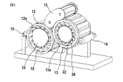
図2は、送給ローラ10および送給トレイ11を備える供給デバイス8と、第1ローラ12(旋回ロータ)と、第2ローラ13(コーミング・ロータ)と、取出しローラ14を備える取出しデバイス9と、周回するカード頂部コーミング・アセンブリ15とを有するロータ・コーミング機械2を示している。ローラ10、12、13および14の回転方向は夫々、湾曲矢印10a、12a、13aおよび14aにより示される。到来する繊維ラップは参照番号16により表されると共に、吐出された繊維ウェブは参照番号17により表される。ローラ10、12、13および14は、相次いで配置される。矢印Aは動作方向を表している。
FIG. 2 shows a
第1ローラ12はその外周縁の領域において、該ローラ12の幅に亙り延在する複数個の第1挟持デバイス18(図3参照)であって各々が上側ニッパ19(把持要素)と下側ニッパ20(対向要素)とから成るという複数個の第1挟持デバイス18を備えている。ローラ12の中心点もしくは枢動軸心を向く上記上側ニッパの一端領域において、各上側ニッパ19は、ローラ12に対して取付けられた枢動軸受24a上に回転可能に取付けられる。下側ニッパ20は、固定されまたは移動可能とされ得るべくローラ12上に取付けられる。上側ニッパ19の自由端部は、ローラ12の周縁部に臨む。上側ニッパ19および下側ニッパ20は、それらが繊維束16、301、302を把持(挟持)し且つそれを解放する様に協働する。
The
第2ローラ13はその外周縁の領域において、該ローラ13の幅に亙り延在する複数個の二部材式挟持デバイス21(図3参照)であって各々が上側ニッパ22(把持要素)と下側ニッパ23(対向要素)とから成るという複数個の二部材式挟持デバイス21を備えている。ローラ13の中心点もしくは枢動軸心を向く上記上側ニッパの一端領域において、各上側ニッパ22は、ローラ13に対して取付けられた枢動軸受24b上に回転可能に取付けられる。下側ニッパ23は、固定され又は移動可能とされ得るべくローラ13上に取付けられる。上側ニッパ22の自由端部は、ローラ13の周縁部に臨む。上側ニッパ22および下側ニッパ23は、それらが繊維束302、303を把持(挟持)し且つそれを解放する(図5(a)乃至図5(c))様に協働する。ローラ12の場合、送給ローラ10と第2ローラ13との間におけるローラ周縁部の回りで各挟持デバイス18は閉じられ(それらは一端にて(不図示の)繊維束を挟持し)、且つ、第2ローラ13と送給ローラ10との間におけるローラ周縁部の回りで各挟持デバイス18は開かれる。ローラ13において、第1ローラ12とドッファ14との間におけるローラ周縁部の回りで各挟持デバイス21は閉じられ(それらは一端にて(不図示の)繊維束を挟持し)、且つ、ドッファ14と第1ローラ12との間におけるローラ周縁部の回りで各挟持デバイス21は開かれる。参照番号50は、たとえばオートレベラ牽伸システムなどの牽伸システムを表している。牽伸システム50は好適には、巻取器ヘッド3aの上方に配置される。参照番号51は、たとえばコンベア・ベルトなどの、駆動されて上昇するコンベアを表している。搬送目的に対しては、上方へと傾斜された板金などを使用することも可能である。
The
図3に依れば2個のカム・ディスク25および26が配備され、該ディスクの回りにて、第1挟持デバイス18を有するローラ12と第2挟持デバイス21を有するローラ13とは夫々、矢印12aおよび13aの方向に回転される。積載された上側ニッパ19および22は、カム・ディスク25、26の外周縁とローラ12、13の内側円筒状表面との間の中間スペース内に配置される。カム・ディスク25および26の回りにおけるローラ12および13の回転により、上側ニッパ19および22は枢動軸心24aおよび24bの回りで回転される。その様にして、第1挟持デバイス18および第2挟持デバイス21の開閉は実施される。
According to FIG. 3, two
図4(a)に依れば、ローラ13およびドッファ14の回転方向13aおよび14aは同一(両方とも時計方向)である。結果として、逆方向の継ぎ合わせが実施される。コーミングされた繊維束304は、上記ドッファの円筒状表面上において屋根瓦の様式で相互に重ねて載置される。ドッファ14の内部においては、固定された篩要素33が在る。ドッファ14の円筒状表面は、空気透過性の開口を有する。篩要素33と内側円筒状表面との間のスペースに負圧-pを掛けることにより、繊維束303はローラ13からドッファ14の外側円筒状表面上へと吸引される。篩要素33から外れたところで、すなわち負圧の無い領域において、繊維束304はドッファ14の外側円筒状表面から取り外され得る。
According to FIG. 4A, the
図4(b)に依ると、ローラ13およびドッファ14の回転方向13aおよび14aは相互に逆である。結果として、同一方向の継ぎ合わせが実施される。コーミングされた繊維束303は、図4(a)に係る構成に関して記述されたのと実質的に同一様式でドッファ14によりローラ13から取り外される。ドッファ14の下流にはスライバ・ファネル34が在り、該ファネル内には、重なり合う繊維束304が進入すると共に、これらの繊維束はコーミング済みスライバ35として出射しまたは引き出される。
According to FIG. 4B, the
同一方向の継ぎ合わせ(図4(b))と逆方向の継ぎ合わせとの間における変更により、繊維掛止方向(繊維の前端掛止および後端掛止)は変更されると共に、該掛止方向は要求事項に従い決定され得る。 By changing between the splicing in the same direction (FIG. 4 (b)) and the splicing in the reverse direction, the fiber hooking direction (fiber front end hooking and rear end hooking) is changed, and the hooking is performed. The direction can be determined according to requirements.
継ぎ合わせローラ14の内側円筒状表面の一部分は、篩要素33によりシールされ得る。
A portion of the inner cylindrical surface of the
継ぎ合わせローラ14からの篩要素33の間隔は、径方向において例えば0.3mmなどの様に可及的に小寸とされねばならない。摺動シールリングを用いる場合には、0mmの間隔が可能である。
The distance between the sieving
本発明に係る装置の動作モードおよび動作シーケンス:
ラップ調製:
複数本のスライバが組み合わされることでラップ16が形成され、一体的に牽伸される。複数枚のラップ16は、相互に重ねて載置されることでダブリングされ得る。結果的に形成されたラップ16は直接的に、ロータ・コーミング機械2の送給要素10内に導入される。材料の流れは、巻回ラップを形成することにより中断されることはない。
Operation mode and operation sequence of the device according to the invention:
Wrap preparation:
A
送給:
フラット・コーミング機械と異なり、上流のラップ16はコンベア要素により連続的に送給される。送給される量は、第1ロータ12(旋回ロータ)のニッパ18(反転ニッパ)の2度の閉じ時点の間において搬送されるラップ16の長さにより決定される。
Supply:
Unlike flat combing machines, the
挟持1:
ラップ16から外方に突出して整列された繊維タフトは、第1ロータ12(旋回ロータ)の挟持ニッパ18(反転ニッパ)により挟持される。第1ロータ12の挟持デバイス18は、摘出機能を前提とする。
Clamping 1:
The fiber tufts arranged to protrude outward from the
摘出:
反転ニッパ18が自身上に配置された旋回ロータ12の回転の結果として、挟持された繊維タフトは送給されたラップから摘出されるが、反転ニッパ8により挟持されないラップ16における繊維は保持される様に、ラップ16に作用する保持力が必要とされる。上記保持力は、送給手段のコンベア要素により、または、送給トレイもしくは頂部コームの如き付加的手段により付与される。上記保持力を生成する上記要素は、頂部コームの機能を前提とする。
Extraction:
As a result of the rotation of the revolving
挟持2:
繊維タフトは、整列されると共に、第2ロータ13(コーミング・ロータ)の挟持デバイス21(コーミング・ニッパ)へと移送される。コーミング・デバイス21が閉じる時点における上記反転ニッパの挟持線と上記コーミング・ニッパの挟持線との間の距離により、上記隔たりが決定される。
Nipping 2:
The fiber tuft is aligned and transferred to the clamping device 21 (combing nipper) of the second rotor 13 (combing rotor). The distance is determined by the distance between the holding wire of the inverted nipper and the holding wire of the combing nipper when the combing
コーミング:
コーミング・ニッパ21から外方に突出する繊維タフトは、挟持されていない繊維であってコーミングにより排除される繊維を包含する。
Combing:
The fiber tuft protruding outward from the combing
取出しローラ(継ぎ合わせローラ)上への吐出および該ローラによる取り込み:
図5(a)乃至図5(c)は、吸引により作用される取出しローラ14上へのローラ13からの梳き取り処理済み繊維束303の吐出、および、吸引により作用される取出しローラ14によるローラ13からの梳き取り処理済み繊維束303の取り込みに関する動作シーケンスを概略的に示しており、各図は時系列的な順序にて相次いでおり、図5(a)に依れば、取出しローラ14の吸引領域内への方向13aにおいてローラ13による繊維束303の搬送が示され、コーミングされた繊維束303の挟持端30IIは、上側ニッパ22と下側ニッパ23とから成り且つ閉じられた挟持デバイス21により挟持されている。図5(b)に依れば、挟持端30IIは継続的に挟持され乍ら、取出しローラ14による自由端部30Iの吸引、および、取出しローラ14の外側面上への自由端部30Iの載置が示される。図5(c)に依れば、挟持デバイス21を開くこと、すなわち下側ニッパ23から離間する方向Pに上側ニッパ22を揚動することによる挟持端30IIの挟持の終結が示される。図5(a)乃至図5(c)は、逆方向継ぎ合わせ(図4(a)を参照)の間における繊維束303の取り外しを示している。参照符号Bは吸引流を表している。
Discharging onto the take-out roller (joining roller) and taking in by the roller:
5 (a) to 5 (c) show the discharge of the
継ぎ合わせ(piecing):
梳き取り処理された繊維タフト303は、取出しローラ14上に載置される。吸引により作用される取出しローラ14の空気透過性表面によれば繊維タフトは、取出しローラ14上に載置されて緊張延伸される。各繊維タフトは相互に重ねて載置され、屋根瓦の様式で重なり合い、繊維部分304のウェブ17を形成する。
Piecing:
ウェブ取り外しおよびコーマ・スライバの形成:
ウェブ17は、吸引により影響されない取出しローラ14上の箇所にて該ローラから取り外されると共に、ファネル34内へと案内される。
Web removal and formation of comba sliver:
The
コーマ・スライバ処置:
結果的に形成されたコーマ・スライバはダブリングかつ牽伸され得る(牽伸システム50)と共に、次に、たとえば巻取器3aによりケンス3b内に、または、ケンス無しスライバ・パッケージの形態(不図示)で投入載置される。
Comb sliver treatment:
The resulting comber sliver can be doubled and drafted (drafting system 50) and then in the
図6に依れば、継ぎ合わせローラ14は、ローラ13(コーミング・ロータ・ローラ)軸心に関して同心的経路上に取付けられる。その目的のために、回転レバー状の2つの保持要素36a、36b(36aのみが示される)が配備され、軸受を形成する該レバー要素の一端36Iは継ぎ合わせローラ14の回転軸と組み合わされ、且つ、軸受を形成する該レバー要素の他端36IIはローラ14の回転軸と組み合わされる。継ぎ合わせローラ14の円筒状表面とローラ13(コーミング・ロータ)の円筒状表面との間の距離aは(不図示の様式で)調節可能である。レバー要素36a、36bは、ローラ13の回転軸の回りで方向Q、Rに回転可能である。
According to FIG. 6, the
図4(a)、図4(b)および図7(a)、図7(b)が示す様に、コーミングされた繊維束304は相互に重ね合わせて載置される(継ぎ合わせ操作)。一方における図7(a)、図7(b)に係る重なり合い長さI1および他方における図7(c)、図7(d)に係る重なり合い長さII2は、継ぎ合わせローラ14とローラ13(コーミング・ロータ)との間の相対速度に依存する。重なり合い長さを変更することにより、ウェブ重量および均一性(CV値)が変更され得る。このことは例えば、材料と適合して行われ得る。
As shown in FIGS. 4 (a), 4 (b), 7 (a), and 7 (b), the combed
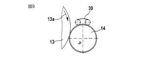
図8および図9に依ると、継ぎ合わせローラ14に対してはウェブ堅固化要素が協働する。上記ウェブ堅固化要素は、コーミング・ロータ13から継ぎ合わせローラ14への移行箇所と、継ぎ合わせローラ14から材料304が降荷される箇所への該継ぎ合わせローラ14からの移行箇所との間に位置される。ひとつ以上のウェブ堅固化要素が使用され得る。たとえば複数個のウェブ堅固化要素が使用されるとき、継ぎ合わせローラ14に関する各要素間の間隔は材料の流れ方向において連続的に減少し得る。ウェブ堅固化要素の形態は、異なり得る。たとえば、圧力付与ローラ37、38(図8)または周回ベルト39(図9)が使用され得る。各ウェブ堅固化要素の表面は、異なる様に構成され得る。たとえば、針布、または、フライス加工もしくはゴム引きされた表面、または、中実ローラが使用され得る。上記ウェブ堅固化要素は、継ぎ合わせローラ14と同一速度を有する。
According to FIGS. 8 and 9, the web hardening element cooperates with the
図10に依ると、継ぎ合わせローラ14の外側円筒状表面にはカバー要素40、41(ケーシング)が配備される。カバー要素40、41(ケーシング)は、必要とされる空気の体積を減少するために、たとえば減圧領域に位置され得る。カバー要素40、41(ケーシング)、または、該ケーシングの一部は、静電防止構成とされ得る。更に、上記継ぎ合わせローラの外側円筒状表面には、空気案内要素42、43が配備される。空気案内要素42、43は、たとえば、コーミング・ロータ13と継ぎ合わせローラ14との間のニップ領域内に取付けられ得る。代替的に、それらの案内要素は、上記継ぎ合わせローラの周縁部の回りにおける異なる箇所、すなわち、該継ぎ合わせローラから材料が取り払われる箇所、または、カバー要素40、41と上記継ぎ合わせローラとの間の箇所に配置され得る。参照番号52は篩要素を表し、且つ、参照番号53は取出しローラを表す。
According to FIG. 10,
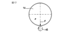
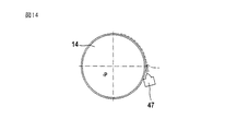
継ぎ合わせローラ14からの材料304の取り外しは(不図示の)ストリッパもしくはブレードを介し、ローラ対44a、44bにより(図11)、減圧ローラにより(不図示)、継ぎ合わせローラ14に関する(図12にて例えばスプリング負荷された)確定挟持ラインを備えるローラ45により、上記継ぎ合わせローラにおける増圧領域46(図13)により、または、継ぎ合わせローラ14からウェブが分離される様に空気が流通するノズル47(図14)により、行われ得る。
Removal of
材料304の取り外しのために確定挟持ラインを備えるローラ45を使用すると、継ぎ合わせローラ14の内側円筒状表面内の篩要素は省略され得る。
Using
カバー要素40、41、空気案内要素42、43、篩要素33、および、ウェブ結合要素37、38、39は、交換可能であると共に、継ぎ合わせローラ14に対するそれらの位置に関して調節可能である。
The
図15に依ると、継ぎ合わせ要素は、減圧源に接続された有孔コンベア・ベルト48の形態である。コンベア・ベルト48の幾何学的構成に依存して、取り外し領域は、継ぎ合わせローラ14を使用するときよりも、コーミング・ロータ13に更に接近して位置され得る。コンベア・ベルト48の幾何学的構成に依存して、コーミング・ロータ13と、継ぎ合わせ要素として使用される該コンベア・ベルト48との間には、更に長寸の移行領域が実現され得る。このことは、たとえば、ロータ周縁部(ローラ13の周縁部)に位置された2つのベルト案内ローラ49a、49bが使用されたときに促進される。
According to FIG. 15, the seaming element is in the form of a
継ぎ合わせローラ14の下流には、牽伸システム50が配置され得る(図2を参照)。牽伸システム50は、調整され得るか、無調整とされ得る。ウェブまたはスライバが引出され得る。
A drafting
上記牽伸システムの上流には、坪量(grammage)を減少する目的でウェブの幅を広げるデバイスが挿入され得る。対応して、牽伸システム50の上流には、スライバの坪量を減少する目的で該スライバの幅を広げるデバイスが挿入され得る。さらに、継ぎ合わせローラ14の下流には、スライバ形成デバイス34(図4(a))およびスライバ投入デバイス3(図1)が配置され得る。
Upstream of the drafting system, a device for widening the web can be inserted in order to reduce the grammage. Correspondingly, a device for expanding the width of the sliver can be inserted upstream of the
図16は図2におけるのと同様のロータ・コーミング機械を示し、この場合、第1ローラ(12)の挟持デバイス18および第2ローラ13の挟持デバイス21に対しては、吸引デバイス52および53が夫々組み合わされる。図16に依ると、挟持デバイス19、20および22、23を夫々備えて回転可能に取付けられたローラ12および13は夫々付加的に吸引チャネル52および56(吸引開口)を備え、これらのチャネルは、供給デバイス8とローラ12との間の吐出の領域において、且つ、ローラ12および13の間における吐出の領域において、搬送されつつある繊維の整列および移動に影響する。その様にして、供給デバイス8から第1ローラ12上への繊維材料の取り込みのための時間、および、第1ローラ12から第2ローラ13上への繊維材料の吐出のための時間は相当に短縮されることから、ニップ速度は増大され得る。吸引開口52、56は夫々、ローラ12および13内に配置され、それらのローラと共に回転する。各挟持デバイス19、20および22、23(ニッパ・デバイス)に対しては、少なくとも一個の吸引開口が組み合わされる。吸引開口52、56は各々、把持要素(上側ニッパ)と対向要素(下側ニッパ)との間に配置される。ロータ12、13の内部には、吸引開口52、56における吸引流により夫々生成された減圧領域53〜55および57〜59が在る。上記減圧は、流れ生成機に接続することにより生成され得る。個々の吸引開口52、56における吸引流は、該吸引流がローラ周縁部上の特定の選択的角度位置においてのみ適用される様に、減圧領域と吸引開口との間において切換えられ得る。上記切換えの目的で、対応する角度位置において開口55および59を夫々備えたバルブもしくはバルブ管54、58が使用され得る。上記把持要素(上側ニッパ)の移動によれば、吸引流の解除も達成され得る。更に、対応する角度位置においてのみ減圧の領域を配置し得る。
FIG. 16 shows a rotor combing machine similar to that in FIG. 2, in which
付加的に、供給デバイス8の領域および/または各ローラ間の移送の領域においては、送出空気流が提供され得る。送給ローラ10の内側には送出空気流の供給源(送風ノズル39)が配置されると共に、該供給源は、上記供給デバイスの空気透過性表面を介し又は空気通路の開口を介し、上記第1ローラの方向において外側に向かい作用する。同様に、供給デバイス8の領域において、送出される空気流を生成する上記要素は、該供給デバイス8の直下または直上において固定的に配置され得る。ローラ12、13間の移送の領域において、送出空気流源は、各ニッパ・デバイスの直下もしくは直上にて第1ローラ12のロータ周縁部に配置され得る。送出空気を生成するために、圧縮空気ノズルまたは空気ブレードが使用され得る。
In addition, in the region of the
吸引流Bは好適には、案内だけでなく、供給デバイス8の領域において、ラップと、摘出されるべきタフトとの間の分離プロセスにも影響して該プロセスを短縮化し得る。
The suction flow B can preferably shorten not only the guidance, but also the separation process between the wrap and the tuft to be extracted in the region of the
付加的な空気案内要素60および側方篩61、62の配備の結果として、上記流れの方向は影響され得ると共に、各ロータにより回転して巻き込まれた空気が分離され得る。その様にして、設定に対する時間が更に短縮化され得る。特に、ラップ上において第1ロータ12と供給デバイス8との間における篩要素、および、上記ローラの各側における篩要素は、有効であることが判明している。
As a result of the deployment of the additional
梳き取り処理された繊維部分303は、第2ローラ13から継ぎ合わせローラ14上へと通過する。
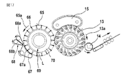
図17に依れば、第1ローラ65(旋回ロータ)においては挟持要素66が存在し、該要素と対置してコンベア・ベルト67が対向要素として配置され、繊維スライバは第1ローラ65上の吸引により保持される。
According to FIG. 17, a clamping
繊維材料は、協働して無限周回する2つのコンベア・ベルト68a、68bから成る供給デバイス68により、ローラ65とコンベア・ベルト67との間の間隙内へと送給される。挟持要素66と、ローラ65に向けて臨むコンベア・ベルト67のベルト部分67aとの間における挟持により、繊維スライバ束はローラ65とコンベア・ベルト67との間の間隙で形成され且つ該間隙から外方に搬送される。引き続き、各スライバ束30の端部領域は、過小圧力領域70に接続された吸引チャネル69の吸引空気流Lによりローラ65の表面に強固に保持される。繊維束30は引き続き、図16に示された第2ローラ13(コーミング・ロータ)上へと移行される。梳き取り処理された繊維材料は、第2ローラ13から継ぎ合わせローラ14上へと進行する。
The fiber material is fed into the gap between the
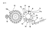
図18に対応しては、図16に示された第1ローラ12(旋回ロータ)が配備される。繊維束30は、第1ローラ12から第2ローラ71(コーミング・ロータ)上へと移行される。第2ローラ71の内側にては、複数個のコーミング要素73を備えた更なるローラ72が回転する。ローラ72は、第2ローラ71の軸心に関して同心的に取付けられる。ローラ72は、コーミング・ロータ71と同一方向にまたは逆方向に連続的に均一に回転する。ニッパ・デバイス74は上側ニッパ75および下側ニッパ76から成り、これらのニッパは、一端にて枢動軸受77の回りで方向M、Nに回転可能である。閉じられた状態においてニッパ・デバイス74は、挟持された繊維タフトをコーミングのためにコーミング要素73に呈示する。繊維タフトとコーミング要素73との間の相対運動により、繊維タフトは梳き取り処理される。ロータ71の内側には、コーミング要素73を清浄化する回転清浄化ローラ78などの清浄化デバイスが在る。同一方向のコーミングの場合、コーミング・ロータ71と、コーミング要素73を備えたローラ72との間の速度比は1より大きい。梳き取り処理された繊維束は、コーミング・ロータ71から継ぎ合わせローラ14上へと進行する。
Corresponding to FIG. 18, the first roller 12 (swivel rotor) shown in FIG. 16 is provided. The
円周速度は、たとえば、送給ローラに対しては約0.2〜1.0m/秒、第1ローラ12に対しては約2.0〜6.0m/秒、第2ローラ13に対しては約2.0〜6.0m/秒、ドッファに対しては約0.4〜1.5m/秒、および、カード回転頂部アセンブリに対しては約1.5〜4.5m/秒である。第1ローラ12および第2ローラ13の直径は、たとえば約0.3m〜0.8mである。
The circumferential speed is, for example, about 0.2 to 1.0 m / sec for the feed roller, about 2.0 to 6.0 m / sec for the
本発明に係るロータ・コーミング機械2を用いると、たとえば3,000〜5,000ニップ/分などの、2,000ニップ/分を超えて達成される。
With the
本発明に係る上記ロータ・コーミング機械を使用すると、梳き取り処理されるべき繊維材料の機械的コーミングが行われ、すなわち、コーミングのために機械的手段が用いられる。コーミングされるべき繊維材料の空気圧的コーミングは無く、すなわち、コーミングのための例えば吸引および/または送出空気流などの空気流は使用されない。 Using the rotor combing machine according to the invention, mechanical combing of the fiber material to be scraped takes place, ie mechanical means are used for combing. There is no pneumatic combing of the fiber material to be combed, i.e. no air flow is used for combing, e.g. suction and / or delivery air flow.
本発明に係る上記ロータ・コーミング機械においては、中断なしで(連続的に)迅速に回転すると共に挟持デバイスを有するローラが存在する。中断され乍ら回転され、段階的に回転され、または、静止状態と回転状態との間で交互変化し乍ら回転するというローラは使用されない。 In the rotor combing machine according to the present invention, there are rollers that rotate rapidly without interruption (continuously) and have a clamping device. Rollers that are interrupted and rotated, rotated in stages, or rotated alternately between a stationary state and a rotating state are not used.
1 コーミング前処理機
2 コーミング機械
3 スライバ投入デバイス
8 供給デバイス
10 送給ローラ
11 送給トレイ
12 ローラ
13 ローラ
16、301、302、303、304 繊維束
18 挟持デバイス
19 上側ニッパ
20 下側ニッパ
21 挟持デバイス
22 上側ニッパ
23 下側ニッパ
30I 自由端部
30II 挟持端
1 Combing pretreatment machine
2 Combing machine
3 Sliver input device
8 Supply device
10 Feed roller
11 Feed tray
12 Laura
13 Laura
16, 30 1 , 30 2 , 30 3 , 30 4 Fiber bundle
18 Clamping device
19 Upper nipper
20 Lower nipper
21 Nipping device
22 Upper nipper
23 Lower nipper
30I free end
30II clamping end
Claims (31)
上記供給手段(8;10、11)の下流には、回転されて搬送される繊維束(16;301〜303)のための挟持デバイス(18、19;21、22、23)を備えると共に回転可能に取付けられて中断なしで回転する少なくとも2つのローラ(12;13)が配置され、
上記挟持デバイスは、上記ローラの周縁部の領域において離間されて分布され、且つ、コーミング作用を生成する手段(コーミング要素)が少なくとも一方の上記ローラ(13)に組み合わされ、
周回手段(14)によるコーミング済み繊維束(303)の自由領域(30I)の取り込みの後で、上記コーミング済み繊維束(303)の挟持端(30II)の挟持は解除可能であり、
継ぎ合わせローラに対しては、コーミング・セグメントによりコーミングされた繊維タフトが供給可能であり、
前記繊維束が前記継ぎ合わせローラにより取り込まれると共に、挟持が終結する後まで、挟持要素と上記繊維束との間の相対運動は開始しないことを特徴とする、装置。 An apparatus for classifying or selecting a fiber bundle composed of woven fibers supplied by a supply means to a fiber classification device, wherein the clamping device clamps the fiber bundle at a predetermined distance from the free end of the fiber bundle. There is a mechanical means that is deployed and generates a combing action from the clamping part of the fiber bundle to the free end, and there is a looping means that is a splicing element to remove the combed fiber material, the loop In the apparatus, the means comprises an air permeable opening on its periphery and at least one subregion of its inner space is connected to a reduced pressure source,
Provided downstream of the supply means (8; 10, 11) is a clamping device (18, 19; 21, 22, 23) for the fiber bundle (16; 30 1 to 30 3 ) to be rotated and conveyed With at least two rollers (12; 13) mounted rotatably and without interruption,
The clamping device is distributed and distributed in the peripheral region of the roller, and means for generating a combing action (combing element) is combined with at least one of the rollers (13),
After taking in the free region (30I) of the combed fiber bundle (30 3 ) by the circulating means (14), the pinching of the pinching end (30II) of the combed fiber bundle (30 3 ) can be released ,
A fiber tuft combed by a combing segment can be supplied to the splicing roller,
The apparatus is characterized in that the fiber bundle is taken in by the splicing roller and the relative movement between the clamping element and the fiber bundle does not start until after the clamping is finished .
Applications Claiming Priority (8)
| Application Number | Priority Date | Filing Date | Title |
|---|---|---|---|
| DE102007030471.6 | 2007-06-29 | ||
| DE102007030472.4 | 2007-06-29 | ||
| DE102007030472 | 2007-06-29 | ||
| DE202007010686 | 2007-06-29 | ||
| DE202007010686.6 | 2007-06-29 | ||
| DE102007030471 | 2007-06-29 | ||
| DE102008004099A DE102008004099A1 (en) | 2007-06-29 | 2008-01-11 | Apparatus for sorting fiber bundle, releases clamping of clamped ends of combed fiber bundles, after take-up of free regions of combed fiber bundles by piecing roller |
| DE102008004099.1 | 2008-01-11 |
Publications (3)
| Publication Number | Publication Date |
|---|---|
| JP2009013564A JP2009013564A (en) | 2009-01-22 |
| JP2009013564A5 JP2009013564A5 (en) | 2011-08-11 |
| JP5290641B2 true JP5290641B2 (en) | 2013-09-18 |
Family
ID=40158707
Family Applications (1)
| Application Number | Title | Priority Date | Filing Date |
|---|---|---|---|
| JP2008168529A Expired - Fee Related JP5290641B2 (en) | 2007-06-29 | 2008-06-27 | Equipment for classifying or selecting fiber bundles made of textile fibers, especially for combing |
Country Status (4)
| Country | Link |
|---|---|
| US (1) | US7926148B2 (en) |
| JP (1) | JP5290641B2 (en) |
| BR (1) | BRPI0801891A2 (en) |
| CH (1) | CH703154B1 (en) |
Cited By (1)
| Publication number | Priority date | Publication date | Assignee | Title |
|---|---|---|---|---|
| WO2020189988A1 (en) * | 2019-03-15 | 2020-09-24 | 신왕수 | Method for manufacturing fiber sheet for recycling woven waste fabric |
Families Citing this family (8)
| Publication number | Priority date | Publication date | Assignee | Title |
|---|---|---|---|---|
| CH703786B1 (en) * | 2007-06-29 | 2012-03-30 | Truetzschler Gmbh & Co Kg | Device for fiber sorting and -selection of a fiber structure made of textile fibers. |
| DE102008004098A1 (en) * | 2007-06-29 | 2009-01-02 | TRüTZSCHLER GMBH & CO. KG | Device for fiber sorting or selection of a fiber structure of textile fibers, in particular for combing, which is fed via feeding means of a fiber sorting device, in particular combing device |
| CH704224B1 (en) * | 2007-06-29 | 2012-06-15 | Truetzschler Gmbh & Co Kg | Apparatus for sorting and selection of fibers of a fiber strand of textile fibers. |
| GB0811207D0 (en) * | 2007-06-29 | 2008-07-23 | Truetzschler Gmbh & Co Kg | Apparatus for the fibre-sorting or fibre-selection of a fibre bundle comprising textile fibres, especially for combing |
| GB0811191D0 (en) * | 2007-06-29 | 2008-07-23 | Truetzschler Gmbh & Co Kg | Apparatus for the fibre-sorting or fibre-selection of a fibre bundle comprising textille fibre, especially for combing |
| ITMI20081097A1 (en) * | 2007-06-29 | 2008-12-30 | Truetzschler Gmbh & Co Kg | EQUIPMENT FOR THE FIBER SORTING OR THE FIBER SELECTION OF A FIBER BAND INCLUDING TEXTILE FIBERS, ESPECIALLY FOR COMBING |
| US7823257B2 (en) * | 2007-06-29 | 2010-11-02 | Fa. Trützschler GmbH & Co. KG | Apparatus for the fibre-sorting or fibre-selection of a fibre bundle comprising textile fibres, especially for combing |
| CN102242420B (en) * | 2011-07-18 | 2013-03-20 | 广东鸿基羽绒制品有限公司 | Device and method for extracting sticky down by deeply processing down |
Family Cites Families (58)
| Publication number | Priority date | Publication date | Assignee | Title |
|---|---|---|---|---|
| DE367482C (en) | 1917-04-17 | 1923-01-22 | Aubrey Edgerton Meyer | Comb drum |
| DE382169C (en) | 1917-09-01 | 1923-09-29 | Riccardo Schleifer | Combing machine |
| US1408780A (en) * | 1918-08-06 | 1922-03-07 | Schleifer Riccardo | Process and machine for combing textile fibers |
| DE399885C (en) | 1920-05-19 | 1924-07-31 | Richard Schleifer | Combing machine |
| US1425059A (en) * | 1921-05-17 | 1922-08-08 | Schleifer Riccardo | Machine for combing textile fibers |
| US1694432A (en) * | 1926-12-06 | 1928-12-11 | Schleifer Carlo | Device for delivering the tufts of textile fibers from combing machines having intermittently-rotating nipper drums |
| US1715473A (en) * | 1927-01-13 | 1929-06-04 | Schleifer Carlo | Machine for combing textile fibers with intermittently-rotating nip drums |
| US1708032A (en) * | 1927-01-27 | 1929-04-09 | Schleifer Carlo | Nip mechanism and controlling apparatus relating thereto in combers for textile fibers |
| US1799066A (en) * | 1928-09-29 | 1931-03-31 | Schleifer Carlo | Reversed needle plate for feeding the sliver in combing machines |
| DE489420C (en) | 1928-09-29 | 1930-01-16 | Carlo Schleifer | Device for feeding the sliver for combing machines |
| US2044460A (en) | 1933-10-11 | 1936-06-16 | Bartram William Bowerbank | Machine for scutching short fibers of flax, jute, hemp, asbestos, and other short fibers |
| US2962772A (en) | 1957-10-18 | 1960-12-06 | Proctor Silex Corp | Movable carriage travel reversing mechanism |
| US3108333A (en) * | 1959-09-04 | 1963-10-29 | Sant Andrea Novara Ohg E Fonde | Adjustment of nippers for combing frames |
| JPS4831927B1 (en) * | 1969-04-08 | 1973-10-03 | ||
| GB2055127B (en) | 1978-10-24 | 1982-09-08 | Stewart & Sons Hacklemakers | Lag or stave for a kirschner beater |
| DE3048501C2 (en) | 1980-12-22 | 1983-06-30 | Zinser Textilmaschinen Gmbh, 7333 Ebersbach | Combing section |
| FI76597C (en) | 1986-11-12 | 1988-11-10 | Partek Ab | FOERFARANDE VID UTLAEGGNING AV MINERALULLBANAS PRIMAERBANA MED HJAELP AV PENDELTRANSPORTOER PAO EN MOTTAGARTRANSPORTOER OCH ARRANGEMANG VID SAODAN PENDELTRANSPORTOER. |
| EP0527355B1 (en) | 1991-08-10 | 1998-04-01 | Rieter Ingolstadt Spinnereimaschinenbau AG | Method and apparatus for pneumatically inserting sliver in a spinning machine |
| EP0571570A1 (en) | 1991-12-09 | 1993-12-01 | Maschinenfabrik Rieter Ag | Combing machine |
| CH684341A5 (en) | 1991-12-09 | 1994-08-31 | Rieter Ag Maschf | Comber. |
| DE59400765D1 (en) | 1993-08-25 | 1996-11-07 | Rieter Ag Maschf | Combing machine |
| DE4328979A1 (en) * | 1993-08-28 | 1995-03-02 | Truetzschler Gmbh & Co Kg | Device on a card or a cleaner for textile fibers, such as cotton or the like. |
| JPH08134725A (en) * | 1994-11-14 | 1996-05-28 | Fuji Tekunika:Kk | Released cotton curlproofing device for cotton layer release roller |
| US5796220A (en) | 1996-07-19 | 1998-08-18 | North Carolina State University | Synchronous drive system for automated textile drafting system |
| DE19811143B4 (en) | 1998-03-14 | 2009-09-17 | TRüTZSCHLER GMBH & CO. KG | Apparatus for feeding and weighing (weighing feeder) textile fibers, in particular cotton and man-made fibers |
| DE59903261D1 (en) | 1998-06-12 | 2002-12-05 | Rieter Ag Maschf | regulating drafting |
| DE19826070B4 (en) | 1998-06-12 | 2015-12-10 | Trützschler GmbH & Co Kommanditgesellschaft | Device on a spinning machine for producing a Faserflockenvlieses, z. B. of cotton, chemical fibers |
| ITMI981618A1 (en) | 1998-07-14 | 2000-01-14 | Marzoli & C Spa | EQUALIZER DEVICE AND PROCEDURE OF THE FEEDING OF THE FIBERS IN THE MATTRESS TO A CARD |
| DE19855571A1 (en) | 1998-12-02 | 2000-06-08 | Truetzschler Gmbh & Co Kg | Device on a spinning machine for producing a fiber structure, e.g. made of cotton, man-made fibers |
| DE19908371A1 (en) | 1999-02-26 | 2000-08-31 | Truetzschler Gmbh & Co Kg | Sliver drawing apparatus takes slivers from cans into straight and parallel paths through sliver thickness monitor to drawing unit giving high production speeds without fiber damage |
| EP1167590A3 (en) | 2000-06-23 | 2002-09-11 | Maschinenfabrik Rieter Ag | Fibre length measuring |
| DE10064655B4 (en) | 2000-12-22 | 2012-01-26 | TRüTZSCHLER GMBH & CO. KG | Device for controlling the at least one card to be supplied amount of fiber flock |
| US6553630B1 (en) | 2001-04-11 | 2003-04-29 | TRüTZSCHLER GMBH & CO. KG | Device for setting the distance between adjoining fiber clamping and fiber transfer locations in a fiber processing system |
| DE10132711A1 (en) | 2001-07-05 | 2003-01-16 | Truetzschler Gmbh & Co Kg | Device on a cleaner, a card or the like. For cleaning and opening textile material, especially cotton |
| DE10139163B4 (en) | 2001-08-09 | 2014-11-13 | Trützschler GmbH & Co Kommanditgesellschaft | Device on a card in which the clothing of the drum opposite cover elements are present |
| DE10207159B4 (en) | 2002-02-20 | 2015-12-17 | Trützschler GmbH & Co Kommanditgesellschaft | Device on a card in which a roller, z. B. drum, a plurality of working elements is assigned |
| DE10231829B4 (en) | 2002-07-15 | 2019-12-12 | Trützschler GmbH & Co Kommanditgesellschaft | Device on a card, carding machine, cleaning machine o. The like. For cotton with at least one Abscheidemesser |
| DE10236778B4 (en) | 2002-08-10 | 2011-05-05 | Rieter Ingolstadt Gmbh | Method and device for drawing at least one sliver |
| DE10259475A1 (en) | 2002-12-19 | 2004-07-01 | Trützschler GmbH & Co KG | Device on a spinning preparation machine, in particular carding machine, cleaner or the like, with a machine cover |
| CH697063A5 (en) | 2003-04-03 | 2008-04-15 | Truetzschler Gmbh & Co Kg | Apparatus at a spinning preparation machine, such as cleaners, NC or carding machine, for recording of fibrous material, eg., Cotton, excreted, from foreign substances and good fibers b |
| DE10320452A1 (en) | 2003-05-08 | 2004-11-25 | Maschinenfabrik Rieter Ag | Process for sliver treatment in combing, can frame for combing machines and machine in combing |
| DE10347811A1 (en) | 2003-10-10 | 2005-06-02 | Trützschler GmbH & Co KG | Device on a track for feeding slivers to a drafting system of at least two pairs of rollers |
| DE102004012236A1 (en) | 2004-03-12 | 2005-09-22 | Trützschler GmbH & Co KG | Device on a spinning preparation machine, e.g. Flake feeder, with a feeding device |
| DE502005000595D1 (en) | 2004-04-13 | 2007-05-31 | Rieter Ag Maschf | Drive for a comber |
| DE502005004034D1 (en) | 2004-08-05 | 2008-06-19 | Rieter Ag Maschf | Comber. |
| DE102005023992A1 (en) | 2005-05-20 | 2006-11-23 | TRüTZSCHLER GMBH & CO. KG | Device on a spinning preparation machine, e.g. Carding, carding, track, combing machine or the like, for determining the mass and / or mass variations of a fiber material, e.g. at least one sliver, non-woven fabric or the like., Of cotton, chemical fibers o. The like. |
| DE102006005390B4 (en) | 2006-02-03 | 2021-08-12 | Trützschler GmbH & Co Kommanditgesellschaft | Device on a card, card or the like. For cleaning fiber material z. B. made of cotton, which comprises a high-speed first or main roller |
| DE102006005391A1 (en) | 2006-02-03 | 2007-08-09 | TRüTZSCHLER GMBH & CO. KG | Device on a card, carding o. The like., For cleaning fiber material z. As cotton, with a high-speed or main roller |
| DE102006005389A1 (en) | 2006-02-03 | 2007-08-09 | TRüTZSCHLER GMBH & CO. KG | Device on a card, carding o. The like., For cleaning fiber material z. B. cotton, which has a high-speed first or main roll |
| DE102007005601A1 (en) | 2006-05-22 | 2007-11-29 | TRüTZSCHLER GMBH & CO. KG | Device on a spinning preparation machine, in particular carding machines, carding machines or the like, for detecting carding process variables |
| DE102007037426A1 (en) | 2006-10-20 | 2008-04-24 | TRüTZSCHLER GMBH & CO. KG | Device for fiber sorting or selection of a fiber structure of textile fibers, in particular for combing |
| GB0811191D0 (en) | 2007-06-29 | 2008-07-23 | Truetzschler Gmbh & Co Kg | Apparatus for the fibre-sorting or fibre-selection of a fibre bundle comprising textille fibre, especially for combing |
| CH704224B1 (en) | 2007-06-29 | 2012-06-15 | Truetzschler Gmbh & Co Kg | Apparatus for sorting and selection of fibers of a fiber strand of textile fibers. |
| DE102008004098A1 (en) | 2007-06-29 | 2009-01-02 | TRüTZSCHLER GMBH & CO. KG | Device for fiber sorting or selection of a fiber structure of textile fibers, in particular for combing, which is fed via feeding means of a fiber sorting device, in particular combing device |
| US7823257B2 (en) | 2007-06-29 | 2010-11-02 | Fa. Trützschler GmbH & Co. KG | Apparatus for the fibre-sorting or fibre-selection of a fibre bundle comprising textile fibres, especially for combing |
| CH703786B1 (en) | 2007-06-29 | 2012-03-30 | Truetzschler Gmbh & Co Kg | Device for fiber sorting and -selection of a fiber structure made of textile fibers. |
| ITMI20081097A1 (en) * | 2007-06-29 | 2008-12-30 | Truetzschler Gmbh & Co Kg | EQUIPMENT FOR THE FIBER SORTING OR THE FIBER SELECTION OF A FIBER BAND INCLUDING TEXTILE FIBERS, ESPECIALLY FOR COMBING |
| GB0811207D0 (en) | 2007-06-29 | 2008-07-23 | Truetzschler Gmbh & Co Kg | Apparatus for the fibre-sorting or fibre-selection of a fibre bundle comprising textile fibres, especially for combing |
-
2008
- 2008-06-25 CH CH00982/08A patent/CH703154B1/en not_active IP Right Cessation
- 2008-06-27 US US12/163,629 patent/US7926148B2/en not_active Expired - Fee Related
- 2008-06-27 BR BRPI0801891-0A patent/BRPI0801891A2/en not_active Application Discontinuation
- 2008-06-27 JP JP2008168529A patent/JP5290641B2/en not_active Expired - Fee Related
Cited By (1)
| Publication number | Priority date | Publication date | Assignee | Title |
|---|---|---|---|---|
| WO2020189988A1 (en) * | 2019-03-15 | 2020-09-24 | 신왕수 | Method for manufacturing fiber sheet for recycling woven waste fabric |
Also Published As
| Publication number | Publication date |
|---|---|
| CH703154B1 (en) | 2011-11-30 |
| BRPI0801891A2 (en) | 2009-03-17 |
| JP2009013564A (en) | 2009-01-22 |
| US7926148B2 (en) | 2011-04-19 |
| US20090000073A1 (en) | 2009-01-01 |
Similar Documents
| Publication | Publication Date | Title |
|---|---|---|
| JP5350689B2 (en) | Apparatus for fiber sorting or fiber selection, in particular combing, of fiber bundles comprising textile fibers fed to a fiber sorting device by a feeding device, in particular to a combing device | |
| JP5290641B2 (en) | Equipment for classifying or selecting fiber bundles made of textile fibers, especially for combing | |
| JP5313560B2 (en) | Device for fiber classification or fiber selection, especially combing, for fiber bundles containing textile fibers | |
| JP5290644B2 (en) | Equipment for fiber classification or fiber selection for combing | |
| JP5275609B2 (en) | A device for selecting and classifying fiber sliver made of woven fiber, especially for fiber classification or fiber selection | |
| JP5479692B2 (en) | Equipment for sorting or selecting fibers for combing fiber bundles | |
| JP5270235B2 (en) | Apparatus for classifying or selecting a fiber bundle composed of woven fibers supplied by a supply means to a fiber classification device, in particular a combing device, in particular for combing. | |
| US20090000071A1 (en) | Apparatus for the fibre-sorting or fibre-selection of a fibre bundle comprising textile fibres, especially for combing | |
| JP5074149B2 (en) | Apparatus for sorting or selecting fiber sliver made of textile fibers, in particular combing and having a feeding device |
Legal Events
| Date | Code | Title | Description |
|---|---|---|---|
| A521 | Written amendment |
Free format text: JAPANESE INTERMEDIATE CODE: A523 Effective date: 20110624 |
|
| A621 | Written request for application examination |
Free format text: JAPANESE INTERMEDIATE CODE: A621 Effective date: 20110624 |
|
| A977 | Report on retrieval |
Free format text: JAPANESE INTERMEDIATE CODE: A971007 Effective date: 20121015 |
|
| A131 | Notification of reasons for refusal |
Free format text: JAPANESE INTERMEDIATE CODE: A131 Effective date: 20121023 |
|
| A521 | Written amendment |
Free format text: JAPANESE INTERMEDIATE CODE: A523 Effective date: 20121116 |
|
| TRDD | Decision of grant or rejection written | ||
| A01 | Written decision to grant a patent or to grant a registration (utility model) |
Free format text: JAPANESE INTERMEDIATE CODE: A01 Effective date: 20130507 |
|
| A61 | First payment of annual fees (during grant procedure) |
Free format text: JAPANESE INTERMEDIATE CODE: A61 Effective date: 20130606 |
|
| R150 | Certificate of patent or registration of utility model |
Ref document number: 5290641 Country of ref document: JP Free format text: JAPANESE INTERMEDIATE CODE: R150 |
|
| R250 | Receipt of annual fees |
Free format text: JAPANESE INTERMEDIATE CODE: R250 |
|
| R250 | Receipt of annual fees |
Free format text: JAPANESE INTERMEDIATE CODE: R250 |
|
| R250 | Receipt of annual fees |
Free format text: JAPANESE INTERMEDIATE CODE: R250 |
|
| LAPS | Cancellation because of no payment of annual fees |