JP5273450B2 - Motor control device - Google Patents

Motor control device Download PDF

Info

Publication number
JP5273450B2
JP5273450B2 JP2008164560A JP2008164560A JP5273450B2 JP 5273450 B2 JP5273450 B2 JP 5273450B2 JP 2008164560 A JP2008164560 A JP 2008164560A JP 2008164560 A JP2008164560 A JP 2008164560A JP 5273450 B2 JP5273450 B2 JP 5273450B2
Authority
JP
Japan
Prior art keywords
motor
unit
phase
axis
rotor
Prior art date
Legal status (The legal status is an assumption and is not a legal conclusion. Google has not performed a legal analysis and makes no representation as to the accuracy of the status listed.)
Expired - Fee Related
Application number
JP2008164560A
Other languages
Japanese (ja)
Other versions
JP2010011542A (en
JP2010011542A5 (en
Inventor
逸人 小松
明 谷沢
雅也 瀬川
裕二 狩集
航也 吉田
Current Assignee (The listed assignees may be inaccurate. Google has not performed a legal analysis and makes no representation or warranty as to the accuracy of the list.)
JTEKT Corp
Original Assignee
JTEKT Corp
Priority date (The priority date is an assumption and is not a legal conclusion. Google has not performed a legal analysis and makes no representation as to the accuracy of the date listed.)
Filing date
Publication date
Application filed by JTEKT Corp filed Critical JTEKT Corp
Priority to JP2008164560A priority Critical patent/JP5273450B2/en
Publication of JP2010011542A publication Critical patent/JP2010011542A/en
Publication of JP2010011542A5 publication Critical patent/JP2010011542A5/ja
Application granted granted Critical
Publication of JP5273450B2 publication Critical patent/JP5273450B2/en
Expired - Fee Related legal-status Critical Current
Anticipated expiration legal-status Critical

Links

Images

Abstract

<P>PROBLEM TO BE SOLVED: To provide a motor controller that makes it possible to continue to drive a motor even when a rotation sensor becomes faulty. <P>SOLUTION: A sensor failure determination unit 25 determines whether or not a resolver 2 is faulty. Under normal conditions under which the resolver 2 is not faulty, a motor 1 is driven by a sine wave by a d- and q-axis target current value computation unit 16, a d- and q-axis voltage command value computation unit 19, a voltage command value coordinate transformation unit 20, a PWM control unit 21, and the like. When the resolver 2 is faulty, the motor 1 is driven by a rectangular wave in a predetermined energization pattern by an energization pattern drive unit 24. When the operating torque detected by a torque sensor 7 is large, driving of the motor 1 by the energization pattern drive unit 24 is stopped so as to avoid step-out. <P>COPYRIGHT: (C)2010,JPO&amp;INPIT

Description

この発明は、ブラシレスモータを駆動するためのモータ制御装置に関する。ブラシレスモータは、たとえば、電動パワーステアリング装置における操舵補助力の発生源として利用される。   The present invention relates to a motor control device for driving a brushless motor. The brushless motor is used, for example, as a source for generating a steering assist force in an electric power steering apparatus.

ブラシレスモータを駆動制御するためのモータ制御装置は、一般に、ロータの回転位置を検出するための回転センサの出力に応じてモータ電流の供給を制御するように構成されている。回転センサとしては、たとえば、ロータ回転位置(電気角)に対応した正弦波信号および余弦波信号を出力するレゾルバが用いられる。
回転センサに故障が生じると、ロータ回転位置を一意に特定することができなくなるから、ブラシレスモータの駆動制御を継続できなくなる。そこで、回転センサの故障時には、ブラシレスモータを停止させている。
A motor control device for driving and controlling a brushless motor is generally configured to control the supply of motor current in accordance with the output of a rotation sensor for detecting the rotational position of the rotor. As the rotation sensor, for example, a resolver that outputs a sine wave signal and a cosine wave signal corresponding to the rotor rotational position (electrical angle) is used.
If a failure occurs in the rotation sensor, it becomes impossible to uniquely specify the rotor rotation position, so that it is impossible to continue the drive control of the brushless motor. Therefore, the brushless motor is stopped when the rotation sensor fails.

回転センサの故障には、回転センサ自身の故障、回転センサの信号線または給電線の断線故障が含まれる。
特開2001−112282号公報
The failure of the rotation sensor includes a failure of the rotation sensor itself and a disconnection failure of the signal line or the feed line of the rotation sensor.
JP 2001-112282 A

電動パワーステアリング装置においては、モータが停止すれば、操舵補助力が得られなくなるから、操舵フィーリングの悪化は避けられない。したがって、回転センサの故障時においても、可能な限りモータの駆動を継続できることが好ましい。
電動パワーステアリング装置の駆動源としてのモータに限らず、他の用途のブラシレスモータにおいても、回転センサの故障後も、可能な限りモータ駆動を継続することが好ましい。
In the electric power steering apparatus, if the motor stops, the steering assist force cannot be obtained, so that the steering feeling is inevitably deteriorated. Therefore, it is preferable that the drive of the motor can be continued as much as possible even when the rotation sensor fails.
Not only the motor as the drive source of the electric power steering apparatus but also the brushless motor for other uses, it is preferable to continue the motor drive as much as possible even after the failure of the rotation sensor.

そこで、この発明の目的は、回転センサに故障が生じたときでも、モータの駆動を継続することができるモータ制御装置を提供することである。   SUMMARY OF THE INVENTION An object of the present invention is to provide a motor control device that can continue to drive a motor even when a failure occurs in a rotation sensor.

の発明は、ロータ(50)と、このロータに対向するステータ(55)とを備えたモータ(1)を制御するためのモータ制御装置(10,10A)であって、前記ロータの回転位置を検出する回転センサ(2)と、この回転センサの正常時には当該回転センサの出力信号に基づいて前記モータを制御する一方で、前記回転センサの故障時には前記正常時の制御態様に対して制限を加えた制御態様で、前記回転センサの出力信号を用いずに、前記モータを制御する制御手段(12,12A)とを含む、モータ制御装置を提供する。なお、括弧内の英数字は後述の実施形態における対応構成要素等を表す。以下、この項において同じ。 This invention includes a rotor (50), a stator that faces the rotor (55) a motor control device for controlling the motor (1) with a (10, 10A), the rotational position of the rotor A rotation sensor (2) for detecting the motor, and when the rotation sensor is normal, the motor is controlled on the basis of an output signal of the rotation sensor. A motor control apparatus including control means (12, 12A) for controlling the motor without using the output signal of the rotation sensor in the added control mode is provided . The alphanumeric characters in parentheses indicate corresponding components in the embodiments described later. The same applies hereinafter.

この構成によれば、回転センサに故障が生じると、回転センサの正常時の制御態様に対して制限を加えた制御態様でモータが制御される。これにより、回転センサの故障時における、いわゆる延命制御が可能になり、モータの回転を継続することができる。
より具体的には、の発明では、前記モータが、車両の舵取り機構に転舵力を付与する転舵用モータ(1)であり、前記制御手段は、前記回転センサの故障時に、車両の操向のための操作部材に加えられる操作トルクが所定のトルク閾値以下であることを条件に、所定の通電パターンで前記モータを駆動するものであり、前記トルク閾値が前記所定の通電パターンで前記モータを駆動するときに脱調が生じるおそれのない範囲で可能な限り大きな値に定められている(24,S5〜S8)。
転舵用モータは、操作部材に加えられる操作トルクに応じた転舵力を舵取り機構に付与する。したがって、操作部材に大きな操作トルクが加えられると、それに応じて、転舵用モータには大きな電流が供給され、大きな転舵トルクが転舵用モータから発生する。回転センサによる正確な回転位置が検出されていないときには、所定の通電パターンによるモータ駆動で大きなトルクを発生させようとすると、モータが脱調するおそれがある。そこで、この発明では、操作部材に加えられる操作トルクが一定値以下であることを条件に、所定の通電パターンによって、モータを駆動するようにしている。こうして、回転センサの故障時において、脱調が生じない条件下で、所定の通電パターンを用いて、モータの駆動が継続される。
According to this configuration, when a failure occurs in the rotation sensor, the motor is controlled in a control mode in which a limitation is imposed on the control mode when the rotation sensor is normal. This enables so-called life extension control when the rotation sensor is out of order, and the rotation of the motor can be continued.
More specifically, the invention of this, the motor is a steering motor which imparts steering force to a steering mechanism of the vehicle (1), wherein the control means of the rotation sensor at the time of failure, the vehicle it on condition operation torque applied to the operation member for steering is below a predetermined torque threshold state, and are not to drive the motor in a predetermined energization pattern, the torque threshold at the predetermined energization pattern unless that have been established to a value that is possible is no possibility of causing step-out when driving the motor (24, S5~S8).
The steering motor imparts a steering force according to the operation torque applied to the operation member to the steering mechanism. Therefore, when a large operating torque is applied to the operating member, a large current is supplied to the steering motor, and a large steering torque is generated from the steering motor. When an accurate rotational position by the rotation sensor is not detected, if the motor is driven by a predetermined energization pattern to generate a large torque, the motor may step out. Therefore, in the present invention, the motor is driven by a predetermined energization pattern on the condition that the operation torque applied to the operation member is a predetermined value or less. Thus, the motor is continuously driven using the predetermined energization pattern under the condition that no step-out occurs when the rotation sensor fails.

回転センサの故障は、既知の手段によって検出可能である。たとえば、回転センサの出力信号が伝送される信号線を電源電圧にプルアップまたはグランド電位にプルダウンしておき、回転センサの出力信号が導出されなくなったときに、当該信号線に電源電圧またはグランド電位が現れるようにしておけばよい。これにより、信号線の電位が電源電圧またはグランド電位に固定されたことに基づいて、回転センサ(信号線の断線および短絡故障を含む)の故障を検出できる。 The failure of the rotation sensor can be detected by known means. For example, when the signal line for transmitting the output signal of the rotation sensor is pulled up to the power supply voltage or pulled down to the ground potential, and the output signal of the rotation sensor is not derived, the power supply voltage or the ground potential is applied to the signal line. You should make it appear. Thereby, based on the fact that the potential of the signal line is fixed to the power supply voltage or the ground potential, it is possible to detect a failure of the rotation sensor (including disconnection of the signal line and short-circuit failure).

以下では、この発明の実施の形態を、添付図面を参照して詳細に説明する。
図1は、この発明の実施形態に係るモータ制御装置を適用した電動パワーステアリング装置の電気的構成を説明するためのブロック図である。この電動パワーステアリング装置は、車両のステアリングホイールに加えられる操作トルクを検出するトルクセンサ7と、車両の速度を検出する車速センサ8と、車両の舵取り機構3に操舵補助力を与えるモータ1と、このモータ1を駆動制御するモータ制御装置10とを備えている。モータ制御装置10は、トルクセンサ7が検出する操作トルクおよび車速センサ8が検出する車速に応じてモータ1を駆動することによって、操舵状況に応じた適切な操舵補助を実現する。モータ1は、たとえば、三相ブラシレスモータであり、図2(a)に図解的に示すように、界磁としてのロータ50と、U相、V相およびW相のステータ巻線51,52,53を含むステータ55とを備えている。モータ1は、ロータの外部にステータを配置したインナーロータ型のものであってもよいし、筒状のロータの内部にステータを配置したアウターロータ型のものであってもよい。
Hereinafter, embodiments of the present invention will be described in detail with reference to the accompanying drawings.
FIG. 1 is a block diagram for explaining an electrical configuration of an electric power steering apparatus to which a motor control apparatus according to an embodiment of the present invention is applied. This electric power steering apparatus includes a torque sensor 7 that detects an operation torque applied to a steering wheel of a vehicle, a vehicle speed sensor 8 that detects the speed of the vehicle, a motor 1 that applies a steering assist force to the steering mechanism 3 of the vehicle, And a motor control device 10 for driving and controlling the motor 1. The motor control device 10 drives the motor 1 in accordance with the operation torque detected by the torque sensor 7 and the vehicle speed detected by the vehicle speed sensor 8, thereby realizing appropriate steering assistance according to the steering situation. The motor 1 is, for example, a three-phase brushless motor, and, as schematically shown in FIG. 2A, a rotor 50 as a field and U-phase, V-phase, and W-phase stator windings 51, 52, And a stator 55 including 53. The motor 1 may be an inner rotor type in which a stator is arranged outside the rotor, or may be an outer rotor type in which a stator is arranged inside a cylindrical rotor.

モータ制御装置10は、電流検出部11、信号処理部としてのマイクロコンピュータ12、および駆動回路13を有する。このモータ制御装置10に、モータ1内のロータの回転位置を検出するレゾルバ2(回転センサ)とともに、前述のトルクセンサ7および車速センサ8が接続されている。
電流検出部11はモータ1のステータ巻線51,52,53を流れる電流を検出する。より具体的には、電流検出部11は、3相(U相、V相およびW相)のステータ巻線51,52,53における相電流をそれぞれ検出する電流検出器11u,11v,11wを有する。
The motor control device 10 includes a current detection unit 11, a microcomputer 12 as a signal processing unit, and a drive circuit 13. The above-described torque sensor 7 and vehicle speed sensor 8 are connected to the motor control device 10 together with the resolver 2 (rotation sensor) that detects the rotational position of the rotor in the motor 1.
The current detector 11 detects the current flowing through the stator windings 51, 52, 53 of the motor 1. More specifically, the current detection unit 11 includes current detectors 11u, 11v, and 11w that detect phase currents in three-phase (U-phase, V-phase, and W-phase) stator windings 51, 52, and 53, respectively. .

マイクロコンピュータ12は、プログラム処理(ソフトウェア処理)によって実現される複数の機能処理部を備えている。これらの複数の機能処理部には、基本目標電流値演算部15、dq軸目標電流値演算部16、dq軸電流演算部17、d軸偏差演算部18d、q軸偏差演算部18q、dq軸電圧指令値演算部19、電圧指令値座標変換部20、PWM(パルス幅変調)制御部21、位置算出部22、通電パターン駆動部24、センサ故障判定部25、切換え部26、トルク判定部27、トルク方向判定部28、偏差演算部29およびPI制御部30などが含まれている。   The microcomputer 12 includes a plurality of function processing units realized by program processing (software processing). The plurality of function processing units include a basic target current value calculation unit 15, a dq axis target current value calculation unit 16, a dq axis current calculation unit 17, a d axis deviation calculation unit 18d, a q axis deviation calculation unit 18q, and a dq axis. Voltage command value calculation unit 19, voltage command value coordinate conversion unit 20, PWM (pulse width modulation) control unit 21, position calculation unit 22, energization pattern drive unit 24, sensor failure determination unit 25, switching unit 26, torque determination unit 27 The torque direction determination unit 28, the deviation calculation unit 29, the PI control unit 30, and the like are included.

駆動回路13は、インバータ回路で構成され、PWM制御部21または通電パターン駆動部24からの制御信号が、切換え部26から与えられるようになっている。この制御信号によって制御されることにより、駆動回路13は、車載バッテリ等の電源(図示せず)からの電力を、モータ1のU相、V相およびW相のステータ巻線51,52,53に供給する。   The drive circuit 13 is configured by an inverter circuit, and a control signal from the PWM control unit 21 or the energization pattern drive unit 24 is supplied from the switching unit 26. By being controlled by this control signal, the drive circuit 13 uses the power from a power source (not shown) such as an in-vehicle battery to supply the U-phase, V-phase, and W-phase stator windings 51, 52, 53 of the motor 1. To supply.

位置算出部22は、レゾルバ2の出力信号に基づいて、モータ1のロータ50の回転位置(電気角)θを算出する。
基本目標電流値演算部15は、トルクセンサ7により検知される操作トルクと、車速センサ8により検出される車速とに基づいて、モータ1の基本目標電流値I*を演算する。基本目標電流値I*は、たとえば、操作トルクの大きさが大きいほど大きく、車速が小さい程大きくなるように定められる。
The position calculation unit 22 calculates the rotational position (electrical angle) θ of the rotor 50 of the motor 1 based on the output signal of the resolver 2.
The basic target current value calculation unit 15 calculates the basic target current value I * of the motor 1 based on the operation torque detected by the torque sensor 7 and the vehicle speed detected by the vehicle speed sensor 8. For example, the basic target current value I * is determined so as to increase as the operating torque increases and to increase as the vehicle speed decreases.

基本目標電流値演算部15により演算された基本目標電流値I*はdq軸目標電流値演算部16に入力される。dq軸目標電流値演算部16は、d軸方向の磁界を生成するためのd軸目標電流値Id *と、q軸方向の磁界を生成するためのq軸目標電流値Iq *とを演算する。ただし、d軸とは、モータ1のロータ50の有する界磁の磁束方向に沿う軸であり、q軸とは、d軸およびロータ回転軸に直交する軸である。dq座標平面はロータ50の回転方向に沿う平面であり、d軸およびq軸は、ロータ50とともに回転する回転座標系を規定する(図2参照)。dq軸目標電流値演算部16における演算は公知の演算式を用いて行うことができる。 The basic target current value I * calculated by the basic target current value calculation unit 15 is input to the dq-axis target current value calculation unit 16. The dq-axis target current value calculation unit 16 calculates a d-axis target current value I d * for generating a magnetic field in the d-axis direction and a q-axis target current value I q * for generating a magnetic field in the q-axis direction. Calculate. However, the d-axis is an axis along the magnetic flux direction of the field of the rotor 50 of the motor 1, and the q-axis is an axis orthogonal to the d-axis and the rotor rotation axis. The dq coordinate plane is a plane along the rotation direction of the rotor 50, and the d axis and the q axis define a rotation coordinate system that rotates together with the rotor 50 (see FIG. 2). The calculation in the dq-axis target current value calculation unit 16 can be performed using a known calculation formula.

電流検出部11から出力される相電流Iu,Iv,Iw(以下、まとめていうときには「三相検出電流Iuvw」という。)はdq軸電流演算部17に入力される。dq軸電流演算部17は、位置算出部22によって算出された回転位置θに基づいて、相電流Iu,Iv,Iwを座標変換することにより、d軸電流値Idおよびq軸電流値Iq(モータ電流値としての検出電流値)を演算する。dq軸電流演算部17における演算は公知の演算式を用いて行うことができる。 Phase currents I u , I v , I w (hereinafter, collectively referred to as “three-phase detection current I uvw ”) output from the current detection unit 11 are input to the dq-axis current calculation unit 17. The dq-axis current calculation unit 17 performs coordinate conversion of the phase currents I u , I v , and I w based on the rotational position θ calculated by the position calculation unit 22, so that the d-axis current value I d and the q-axis current are converted. The value I q (the detected current value as the motor current value) is calculated. The calculation in the dq axis current calculation unit 17 can be performed using a known calculation formula.

d軸偏差演算部18dは、d軸目標電流値Id *とd軸電流Idとの間の偏差(d軸偏差)δIdを求める。同様に、q軸偏差演算部18qは、q軸目標電流値Iq *とq軸電流Iqとの間の偏差(q軸偏差)δIqを求める。
dq軸電圧指令値演算部19は、d軸偏差δIdに対応するd軸電圧指令値Vd *とq軸偏差δIqに対応するq軸電圧指令値Vq *とを求める。
The d-axis deviation calculating unit 18d obtains a deviation (d-axis deviation) δI d between the d-axis target current value I d * and the d-axis current I d . Similarly, the q-axis deviation calculating unit 18q obtains a deviation (q-axis deviation) δI q between the q-axis target current value I q * and the q-axis current I q .
The dq-axis voltage command value calculation unit 19 obtains a d-axis voltage command value V d * corresponding to the d-axis deviation δI d and a q-axis voltage command value V q * corresponding to the q-axis deviation δI q .

電圧指令値座標変換部20は、位置算出部22によって算出された回転位置θに基づいて、d軸電圧指令値Vd *およびq軸電圧指令値Vq *の座標変換を行い、U相ステータ巻線51、V相ステータ巻線52およびW相ステータ巻線53にそれぞれ印加すべき印加電圧指令値Vu *,Vv *,Vw *を演算する。電圧指令値座標変換部20における演算は公知の演算式を用いて行えばよい。 The voltage command value coordinate conversion unit 20 performs coordinate conversion of the d-axis voltage command value V d * and the q-axis voltage command value V q * on the basis of the rotational position θ calculated by the position calculation unit 22, and performs a U-phase stator. Applied voltage command values V u * , V v * , and V w * to be applied to the winding 51, the V-phase stator winding 52, and the W-phase stator winding 53 are calculated. The calculation in the voltage command value coordinate conversion unit 20 may be performed using a known calculation formula.

PWM制御部21は、印加電圧指令値Vu *,Vv *,Vw *に対応するデューティ比を有するパルス信号である各相のPWM制御信号を生成する。このPWM信号が切換え部26を介して駆動回路13に与えられることにより、d軸電圧指令値Vd *およびq軸電圧指令値Vq *に対応する電圧が駆動回路13から各相のステータ巻線51,52,53に印加され、ロータ50の回転力が発生する。 The PWM control unit 21 generates a PWM control signal for each phase, which is a pulse signal having a duty ratio corresponding to the applied voltage command values V u * , V v * , and V w * . By applying this PWM signal to the drive circuit 13 via the switching unit 26, voltages corresponding to the d-axis voltage command value V d * and the q-axis voltage command value V q * are transferred from the drive circuit 13 to the stator windings of each phase. Applied to the lines 51, 52, 53, a rotational force of the rotor 50 is generated.

通電パターン駆動部24は、120度通電方式による所定の通電パターンに従ってモータ1を駆動するための制御信号を生成する。通電パターン駆動部24は、PWMデューティ設定部24aを備えている。通電パターン駆動部24は、PWMデューティ設定部24aによって設定されたデューティでパルス幅変調された矩形波駆動信号を生成する。
センサ故障判定部25は、レゾルバ2の故障の有無を判定する。たとえば、センサ故障判定部25は、レゾルバ2の信号線2aに導出される信号を監視することによって、レゾルバ2の故障、信号線2aの断線故障、信号線2aの接地故障を検出することができる。より具体的には、レゾルバ2とモータ制御装置10との間の信号線2aをプルアップ抵抗を介して電源電位に接続したり、プルダウン抵抗を介して接地電位に接続したりする構成をとることができる。この場合、信号線2aが断線すると、当該信号線2aには、レゾルバ2からの信号(正弦信号または余弦信号)が導出されなくなり、代わりに、当該信号線2aは、電源電位または接地電位に固定される。そこで、センサ故障判定部25は、信号線2aが電源電位または接地電位に固定されているかどうかを判定することで、レゾルバ2の故障(信号線の故障を含む)の有無を判定することができる。むろん、レゾルバ2の故障検出には、その他の公知の方法を適用してもよい。
The energization pattern driving unit 24 generates a control signal for driving the motor 1 in accordance with a predetermined energization pattern by the 120-degree energization method. The energization pattern driving unit 24 includes a PWM duty setting unit 24a. The energization pattern driving unit 24 generates a rectangular wave driving signal that is pulse-width modulated with the duty set by the PWM duty setting unit 24a.
The sensor failure determination unit 25 determines whether or not there is a failure in the resolver 2. For example, the sensor failure determination unit 25 can detect a failure of the resolver 2, a disconnection failure of the signal line 2a, and a grounding failure of the signal line 2a by monitoring a signal derived to the signal line 2a of the resolver 2. . More specifically, the signal line 2a between the resolver 2 and the motor control device 10 is connected to the power supply potential via a pull-up resistor or connected to the ground potential via a pull-down resistor. Can do. In this case, when the signal line 2a is disconnected, the signal (sine signal or cosine signal) from the resolver 2 is not derived to the signal line 2a. Instead, the signal line 2a is fixed to the power supply potential or the ground potential. Is done. Therefore, the sensor failure determination unit 25 can determine whether or not the resolver 2 has failed (including signal line failure) by determining whether or not the signal line 2a is fixed at the power supply potential or the ground potential. . Of course, other known methods may be applied to the failure detection of the resolver 2.

切換え部26は、センサ故障判定部25が故障なしと判定している通常状態においては、PWM制御部21からの制御信号を駆動回路13に供給する。一方、センサ故障判定部25が故障ありと判定している故障状態においては、切換え部26は、通電パターン駆動部24が生成する制御信号を駆動回路13に供給する。
トルク判定部27は、トルクセンサ7によって検出される操作トルクの大きさを所定のトルク閾値(たとえば、7Nm)と比較し、その比較結果を通電パターン駆動部24に与える。トルク閾値は、通電パターン駆動部24によって所定の通電パターンでモータ1を駆動するときに、脱調が生じるおそれのない範囲で可能な限り大きな値に定められる。
The switching unit 26 supplies a control signal from the PWM control unit 21 to the drive circuit 13 in a normal state in which the sensor failure determination unit 25 determines that there is no failure. On the other hand, in a failure state in which the sensor failure determination unit 25 determines that there is a failure, the switching unit 26 supplies the drive circuit 13 with a control signal generated by the energization pattern drive unit 24.
The torque determination unit 27 compares the magnitude of the operation torque detected by the torque sensor 7 with a predetermined torque threshold (for example, 7 Nm), and gives the comparison result to the energization pattern driving unit 24. The torque threshold is determined to be as large as possible within a range where there is no possibility of stepping out when the motor 1 is driven with a predetermined energization pattern by the energization pattern driving unit 24.

トルク方向判定部28は、トルクセンサ7によって検出される操作トルクの方向が右回りトルクか、左回りトルクかを判定し、その判定結果を通電パターン駆動部24に与える。ただし、右回り方向とは、舵取り車輪を右方向に転舵させる方向に対応し、左回り方向とは、舵取り車輪を左方向に転舵させる方向に対応するものとする。
偏差演算部29は、基本目標電流値演算部15によって設定される基本目標電流値I*と、UVW/dq座標変換部17が生成するq軸電流値Iqを変換部31で変換して得られる相電流振幅(検出電流値)I(後述の式(2)参照。I=−√(2/3)Iq)との偏差δI(=I*−I)を求める。
The torque direction determination unit 28 determines whether the direction of the operation torque detected by the torque sensor 7 is clockwise torque or counterclockwise torque, and gives the determination result to the energization pattern driving unit 24. However, the clockwise direction corresponds to the direction in which the steering wheel is steered in the right direction, and the counterclockwise direction corresponds to the direction in which the steered wheel is steered in the left direction.
The deviation calculation unit 29 is obtained by converting the basic target current value I * set by the basic target current value calculation unit 15 and the q-axis current value I q generated by the UVW / dq coordinate conversion unit 17 by the conversion unit 31. The deviation δI (= I * −I) from the phase current amplitude (detected current value) I (refer to equation (2) described later, I = −√ (2/3) I q ) is obtained.

PI制御部30は、偏差δIに対する比例積分制御を行うことによって、印加電圧指令値Vu *,Vv *,Vw *を求める。
通電パターン駆動部24に備えられたPWMデューティ設定部24aは、PI制御部30によって演算される印加電圧指令値Vu *,Vv *,Vw *に応じたPWMデューティを設定する。
The PI control unit 30 obtains the applied voltage command values V u * , V v * , and V w * by performing proportional-integral control on the deviation δI.
The PWM duty setting unit 24 a provided in the energization pattern driving unit 24 sets the PWM duty corresponding to the applied voltage command values V u * , V v * , and V w * calculated by the PI control unit 30.

図3は、駆動回路13の具体的な構成を説明するための電気回路図である。モータ1のU相ステータ巻線51、V相ステータ巻線52およびW相ステータ巻線53に対して、U相電流Iu、V相電流IvおよびW相電流Iwが駆動回路13から与えられるようになっている。
駆動回路13は、U相に対応した直列回路40Uと、V相に対応した直列回路40Vと、W相に対応した直列回路40Wとを備え、これらが電源(車載バッテリ。図示せず)に対して並列に接続されている。直列回路40Uは、ハイサイドパワースイッチング素子41Uと、ローサイドパワースイッチング素子42Uとを直列に接続し、これらの間の接続点43Uをモータ1のU相ステータ巻線51に接続して構成されている。同様に、直列回路40Vは、ハイサイドパワースイッチング素子41Vと、ローサイドパワースイッチング素子42Vとを直列に接続し、これらの間の接続点43Vをモータ1のV相ステータ巻線52に接続して構成されている。また、直列回路40Wは、ハイサイドパワースイッチング素子41Wと、ローサイドパワースイッチング素子42Wとを直列に接続し、これらの間の接続点43Wをモータ1のW相ステータ巻線53に接続して構成されている。切換え部26からのPWM制御信号は、必要に応じて増幅されて、パワースイッチング素子41U,42U;41V,42V;41W,42Wの各ゲートに与えられるようになっている。
FIG. 3 is an electric circuit diagram for explaining a specific configuration of the drive circuit 13. A U-phase current I u , a V-phase current I v and a W-phase current I w are given from the drive circuit 13 to the U-phase stator winding 51, the V-phase stator winding 52 and the W-phase stator winding 53 of the motor 1. It is supposed to be.
The drive circuit 13 includes a series circuit 40U corresponding to the U phase, a series circuit 40V corresponding to the V phase, and a series circuit 40W corresponding to the W phase, which are for a power supply (on-vehicle battery, not shown). Connected in parallel. The series circuit 40U is configured by connecting a high-side power switching element 41U and a low-side power switching element 42U in series, and connecting a connection point 43U between them to the U-phase stator winding 51 of the motor 1. . Similarly, the series circuit 40V includes a high-side power switching element 41V and a low-side power switching element 42V connected in series, and a connection point 43V between them is connected to the V-phase stator winding 52 of the motor 1. Has been. The series circuit 40W is configured by connecting a high-side power switching element 41W and a low-side power switching element 42W in series, and connecting a connection point 43W between them to the W-phase stator winding 53 of the motor 1. ing. The PWM control signal from the switching unit 26 is amplified as necessary and is supplied to the gates of the power switching elements 41U and 42U; 41V and 42V; 41W and 42W.

dq軸電圧指令値演算部19は、正弦波駆動のための電圧指令値Vd *,Vq *を生成し、それに応じた制御信号がPWM制御部21から生成される。したがって、PWM制御部21が生成した制御信号が切換え部26から駆動回路13に供給されるときには、モータ1のU相、V相およびW相ステータ巻線51,52,53に正弦波状の相電流Iu,Iv,Iwが流れるように、モータ1が正弦波駆動される。 The dq axis voltage command value calculation unit 19 generates voltage command values V d * and V q * for sine wave drive, and a control signal corresponding to the voltage command values V d * and V q * is generated from the PWM control unit 21. Therefore, when the control signal generated by the PWM control unit 21 is supplied from the switching unit 26 to the drive circuit 13, sinusoidal phase currents are supplied to the U-phase, V-phase, and W-phase stator windings 51, 52, 53 of the motor 1. The motor 1 is driven in a sine wave so that I u , I v , and I w flow.

図4Aおよび図4Bは、通電パターン駆動部24が生成する制御信号の一例を示す波形図であり、図4Aは、モータ1から右回り方向のトルクを発生させるべきときの波形(通電パターン)を示し、図4Bはモータ1から左まわり方向のトルクを発生させるべきときの波形(通電パターン)を示す。
通電パターン駆動部24は、各相のハイサイドパワースイッチング素子41U,41V,41Wに対して、それぞれ120度の電気角の期間に渡って、PWMパルスからなる制御信号を出力する。各相のハイサイドパワースイッチング素子41U,41V,41WにPWMパルスが与えられる120度の期間は、120度ずつ位相がずれている。つまり、ハイサイドパワースイッチング素子41U,41V,41Wは、120度ずつ位相がずらされた各120度の期間に、循環的にPWM制御される。このPWM制御される各120度の期間に、PWMデューティに応じた電圧がモータ1の各相に印加される。
4A and 4B are waveform diagrams illustrating an example of a control signal generated by the energization pattern driving unit 24. FIG. 4A illustrates a waveform (energization pattern) when torque in the clockwise direction from the motor 1 should be generated. 4B shows a waveform (energization pattern) when torque in the counterclockwise direction from the motor 1 should be generated.
The energization pattern driving unit 24 outputs a control signal including a PWM pulse to the high-side power switching elements 41U, 41V, and 41W of each phase over a period of 120 degrees electrical angle. During the 120-degree period in which the PWM pulse is applied to the high-side power switching elements 41U, 41V, 41W of the respective phases, the phases are shifted by 120 degrees. That is, the high-side power switching elements 41U, 41V, and 41W are cyclically PWM-controlled during each 120-degree period whose phase is shifted by 120 degrees. A voltage corresponding to the PWM duty is applied to each phase of the motor 1 during each 120-degree period under PWM control.

一方、各相のローサイドパワースイッチング素子42U,42V,42Wは、各相のハイサイドパワースイッチング素子41U,41V,41WがPWM制御される期間から電気角で60度シフトされた120度の期間に渡ってオン状態とされ、残余の期間はオフ状態とされる。したがって、各相のローサイドパワースイッチング素子42U,42V,42Wがオン状態となる120度の期間は、120度ずつ位相がずれている。つまり、ローサイドパワースイッチング素子42U,42V,42Wは、120度ずつ位相がずらされた各120度の期間に、循環的にオン状態となる。   On the other hand, the low-side power switching elements 42U, 42V, and 42W of each phase extend over a period of 120 degrees that is shifted by 60 degrees in electrical angle from the period in which the high-side power switching elements 41U, 41V, and 41W of each phase are PWM-controlled. Are turned on, and the remaining period is turned off. Accordingly, the phase is shifted by 120 degrees during the 120-degree period in which the low-side power switching elements 42U, 42V, and 42W of the respective phases are turned on. That is, the low-side power switching elements 42U, 42V, and 42W are cyclically turned on during each 120-degree period whose phase is shifted by 120 degrees.

各相において、ハイサイドパワースイッチング素子41U,41V,41Wおよびローサイドパワースイッチング素子42U,42V,42Wのいずれもがオフ状態とされる期間には、対応する相のステータ巻線には誘起電圧のみが現れる。
図4Aに示す右回り通電パターン波形では、U相駆動波形に対して120度だけV相駆動波形の位相が遅れ、V相駆動波形に対して120度だけW相駆動波形の位相が遅れているのが分かる。これに対して、図4Bに示す左回り通電パターン波形では、W相駆動波形に対して120だけV相駆動波形の位相が遅れ、V相駆動波形に対して120度だけU相駆動波形の位相が遅れているのが分かる。
In each phase, during the period in which all of the high-side power switching elements 41U, 41V, 41W and the low-side power switching elements 42U, 42V, 42W are in the OFF state, only the induced voltage is applied to the stator winding of the corresponding phase. appear.
In the clockwise energization pattern waveform shown in FIG. 4A, the phase of the V-phase drive waveform is delayed by 120 degrees with respect to the U-phase drive waveform, and the phase of the W-phase drive waveform is delayed by 120 degrees with respect to the V-phase drive waveform. I understand. On the other hand, in the counterclockwise energization pattern waveform shown in FIG. 4B, the phase of the V-phase drive waveform is delayed by 120 with respect to the W-phase drive waveform, and the phase of the U-phase drive waveform by 120 degrees with respect to the V-phase drive waveform. You can see that is behind.

図5は、マイクロコンピュータ12が所定の制御周期毎に繰り返し実行する制御内容を説明するためのフローチャートである。マイクロコンピュータ12は、トルクセンサ7、車速センサ8、レゾルバ2および電流検出部11の各出力信号を取り込む(ステップS1)。基本目標電流値演算部15は、トルクセンサ7が検出した操作トルクおよび車速センサ8が検出した車速に基づいて、基本目標電流値I*を演算する(ステップS2)。一方、センサ故障判定部25は、信号線2aに導出される信号に基づいて、レゾルバ2の故障の有無を判定する(ステップS3)。 FIG. 5 is a flowchart for explaining the control contents that the microcomputer 12 repeatedly executes at predetermined control cycles. The microcomputer 12 takes in the output signals of the torque sensor 7, the vehicle speed sensor 8, the resolver 2, and the current detector 11 (step S1). The basic target current value calculation unit 15 calculates the basic target current value I * based on the operation torque detected by the torque sensor 7 and the vehicle speed detected by the vehicle speed sensor 8 (step S2). On the other hand, the sensor failure determination unit 25 determines the presence or absence of a failure of the resolver 2 based on a signal derived to the signal line 2a (step S3).

レゾルバ2に故障がなければ(ステップS3:NO)、通常の制御が実行される(ステップS4)。より具体的には、dq軸目標電流値演算部16によってd軸目標電流値Id *およびq軸目標電流値Iq *が設定される。また、電流検出部11が検出する三相検出電流Iuvwが、dq軸電流演算部17で座標変換され、d軸検出電流Idおよびq軸検出電流Iqが求められる。d軸偏差演算部18dおよびq軸偏差演算部18qは、d軸電流偏差δId(=Id *−Id)およびq軸電流偏差δIq(=Iq *−Iq)をそれぞれ求める。dq軸電圧指令値演算部19は、電流偏差δId,δIqに対するPI(比例積分)演算等を行うことにより、d軸電圧指令値Vd *およびq軸電圧指令値Vq *を生成する。これらが電圧指令値座標変換部20において座標変換されることによって、UVW相の電圧指令値Vu *,Vv *,Vw *が生成される。これらの電圧指令値Vu *,Vv *,Vw *に対応するPWM制御信号がPWM制御部21によって生成される。切換え部26は、このPWM制御信号を駆動回路13に供給する。dq軸電流演算部17および電圧指令値座標変換部20における座標変換演算のために、位置算出部22によって算出される回転位置θが用いられる。 If there is no failure in the resolver 2 (step S3: NO), normal control is executed (step S4). More specifically, the d-axis target current value I d * and the q-axis target current value I q * are set by the dq-axis target current value calculation unit 16. Further, the three-phase detection current I uvw detected by the current detection unit 11 is coordinate-converted by the dq-axis current calculation unit 17 to obtain the d-axis detection current I d and the q-axis detection current I q . The d-axis deviation calculating unit 18d and the q-axis deviation calculating unit 18q obtain a d-axis current deviation δI d (= I d * −I d ) and a q-axis current deviation δI q (= I q * −I q ), respectively. The dq-axis voltage command value calculation unit 19 generates a d-axis voltage command value V d * and a q-axis voltage command value V q * by performing PI (proportional integration) calculation and the like on the current deviations δI d and δI q . . These are subjected to coordinate conversion by the voltage command value coordinate conversion unit 20 to generate UVW phase voltage command values V u * , V v * , V w * . A PWM control signal corresponding to these voltage command values V u * , V v * , V w * is generated by the PWM control unit 21. The switching unit 26 supplies this PWM control signal to the drive circuit 13. The rotation position θ calculated by the position calculation unit 22 is used for the coordinate conversion calculation in the dq axis current calculation unit 17 and the voltage command value coordinate conversion unit 20.

一方、センサ故障判定部25によって、レゾルバ2に故障が生じていると判定されると(ステップS3:YES)、トルク判定部27は、操作トルクが所定のトルク閾値(たとえば、7Nm)以下かどうかを判定する(ステップS5)。操作トルクがトルク閾値以下であれば(ステップS5:YES)、トルク方向判定部28は、トルクセンサ7の出力信号に基づいて、操作トルクの方向が右回り方向か左回り方向かを判定する(ステップS6)。操作トルク方向が右回り方向であれば、通電パターン駆動部24は、右回り通電パターン(図4A参照)に従う矩形波駆動信号を生成し(ステップS7)、操作トルク方向が左回り方向であれば、通電パターン駆動部24は、左回り通電パターン(図4B参照)に従う矩形波駆動信号を生成する(ステップS8)。   On the other hand, when the sensor failure determination unit 25 determines that a failure has occurred in the resolver 2 (step S3: YES), the torque determination unit 27 determines whether the operation torque is equal to or less than a predetermined torque threshold (for example, 7 Nm). Is determined (step S5). If the operation torque is equal to or less than the torque threshold (step S5: YES), the torque direction determination unit 28 determines whether the direction of the operation torque is clockwise or counterclockwise based on the output signal of the torque sensor 7 ( Step S6). If the operation torque direction is clockwise, the energization pattern drive unit 24 generates a rectangular wave drive signal according to the clockwise energization pattern (see FIG. 4A) (step S7), and if the operation torque direction is counterclockwise. The energization pattern drive unit 24 generates a rectangular wave drive signal according to the counterclockwise energization pattern (see FIG. 4B) (step S8).

このとき、PWMデューティ設定部24aは、PI制御部30によって求められた電圧指令値Vu *,Vv *,Vw *に対応するデューティを設定する。この設定されたデューティでパルス幅変調されたPWM制御信号が通電パターン駆動部24から生成されることになる。切換え部26は、このPWM制御信号を駆動回路13に供給する。つまり、図4Aおよび図4Bに示されているように、各相のハイサイドパワースイッチング素子41U,41V,41Wが、120度ずつ位相がずれた各120度の期間に循環的にPWM制御され、この各120度の期間において、前記設定されたデューティに応じた電圧がモータ1の各相に印加される。 At this time, the PWM duty setting unit 24a sets the duty corresponding to the voltage command values V u * , V v * , and V w * obtained by the PI control unit 30. A PWM control signal that is pulse-width modulated with the set duty is generated from the energization pattern driving unit 24. The switching unit 26 supplies this PWM control signal to the drive circuit 13. That is, as shown in FIG. 4A and FIG. 4B, the high-side power switching elements 41U, 41V, and 41W of each phase are cyclically PWM-controlled during each 120-degree period that is 120 degrees out of phase. In each 120 degree period, a voltage corresponding to the set duty is applied to each phase of the motor 1.

一方、操作トルクがトルク閾値を超えている場合(ステップS5:NO)には、通電パターン駆動部24は、制御信号を生成しない。これにより、モータ1が停止される。操作トルクがトルク閾値を超えるほど大きいときには、一定の通電パターンでの駆動では、モータ1が脱調するおそれがある。そこで、この実施形態では、通電パターン駆動部24によって所定の通電パターンでモータ1を駆動するときには、操作トルクがトルク閾値以下であることを条件としている。換言すれば、トルク閾値は、図4Aおよび図4Bに示す所定の通電パターンによる駆動でモータ1の脱調を生じさせることなく正常に駆動することができる範囲で可能な限り大きな値に定められている。   On the other hand, when the operating torque exceeds the torque threshold (step S5: NO), the energization pattern driving unit 24 does not generate a control signal. Thereby, the motor 1 is stopped. When the operation torque is large enough to exceed the torque threshold, the motor 1 may step out in driving with a constant energization pattern. Therefore, in this embodiment, when the motor 1 is driven with a predetermined energization pattern by the energization pattern driving unit 24, it is a condition that the operation torque is equal to or less than the torque threshold value. In other words, the torque threshold value is determined to be as large as possible within a range in which the motor 1 can be driven normally without causing the step-out of the motor 1 by the driving with the predetermined energization pattern shown in FIGS. 4A and 4B. Yes.

以上のように、この実施形態によれば、レゾルバ2に故障が生じた場合には、通電パターン駆動部24が生成する所定の通電パターンの矩形波駆動信号によって、120度通電方式による矩形波駆動が行われる。これにより、モータ1の回転を継続することができるので、舵取り機構3に対して操舵補助力を与えることができる。
また、レゾルバ2が正常のときには正弦波駆動が行われるのに対して、レゾルバ2に故障が生じているときには、矩形波駆動が行われるので、故障時には、トルクリップルが生じることになる。これにより、運転者に対して、異常発生を報知することができ、早期修理を促すことができる。
As described above, according to this embodiment, when a failure occurs in the resolver 2, the rectangular wave drive by the 120-degree energization method is performed by the rectangular wave drive signal of the predetermined energization pattern generated by the energization pattern drive unit 24. Is done. Thereby, since the rotation of the motor 1 can be continued, a steering assist force can be applied to the steering mechanism 3.
Further, when the resolver 2 is normal, sinusoidal wave driving is performed, whereas when the resolver 2 has a failure, rectangular wave driving is performed, so that torque ripple occurs at the time of failure. As a result, the driver can be notified of the occurrence of abnormality and prompt early repair.

図6は、参考形態に係る電動パワーステアリング装置の電気的構成を示すブロック図である。この図6において、前述の図1に示された各部に対応する部分には、同一の参照符号を付して示す。この実施形態は、誘起電圧検出部35、回転速度推定部36および位相推定部37が備えられており、トルク判定部27およびトルク方向判定部28が備えられていない点が、前述の実施形態とは異なる。 FIG. 6 is a block diagram showing an electrical configuration of the electric power steering apparatus according to the reference embodiment. In FIG. 6, parts corresponding to those shown in FIG. 1 are given the same reference numerals. This embodiment, the induced voltage detection unit 35 is provided with rotation speed estimation unit 36 and the phase estimator 37, the point that the torque determination unit 27 and the torque direction determining unit 28 is not provided, the implementation form described above Is different.

誘起電圧検出部35は、モータ1の各相の誘起電圧を所定のサンプリング周期毎に測定する。より具体的には、各相のステータ巻線51,52,53に電圧が印加されない期間(各相のハイサイドおよびローサイドのパワースイッチング素子がいずれもオフとなる期間。図4Aおよび図4B参照)に、当該巻線に誘導される電圧を検出する。
回転速度推定部36は、誘起電圧検出部35によって検出される誘起電圧から、ロータの回転速度を推定する。たとえば、隣接する2つのサンプリング点での誘起電圧の変化を正弦波にフィッティングすることによって、ロータ回転速度を推定することができる。
The induced voltage detection unit 35 measures the induced voltage of each phase of the motor 1 for each predetermined sampling period. More specifically, a period in which no voltage is applied to the stator windings 51, 52, 53 of each phase (a period in which both the high-side and low-side power switching elements of each phase are off. See FIGS. 4A and 4B). In addition, a voltage induced in the winding is detected.
The rotation speed estimation unit 36 estimates the rotation speed of the rotor from the induced voltage detected by the induced voltage detection unit 35. For example, the rotor rotational speed can be estimated by fitting a change in the induced voltage at two adjacent sampling points into a sine wave.

位相推定部37は、誘起電圧検出部35によって検出される誘起電圧および回転速度推定部36によって推定されるロータ回転速度に基づいて、ロータの位相(電気角)を推定する。具体的には、所定のサンプリング周期で検出される誘起電圧を正弦波にフィッティングすることによって、誘起電圧の正負が切り換わるゼロクロス点を推定できる。こうして推定されるゼロクロス点からの経過時間およびロータ回転速度に基づいて、ロータの位相が推定される。この推定された位相に基づいて、通電パターン駆動部24は、相切換えタイミングを求める。通電パターン駆動部24は、求められた相切換えタイミングに基づいて、各相の矩形波駆動信号の立ち上げおよび立ち下げを行う。より具体的には、図4Aおよび図4Bに示されているように、60度毎の位相で駆動回路13のパワースイッチング素子のオン/オフパターンを切り換える。   The phase estimation unit 37 estimates the rotor phase (electrical angle) based on the induced voltage detected by the induced voltage detection unit 35 and the rotor rotation speed estimated by the rotation speed estimation unit 36. Specifically, by fitting an induced voltage detected at a predetermined sampling period to a sine wave, it is possible to estimate a zero cross point at which the polarity of the induced voltage switches. The phase of the rotor is estimated based on the elapsed time from the zero cross point estimated in this way and the rotor rotational speed. Based on the estimated phase, the energization pattern driving unit 24 obtains the phase switching timing. The energization pattern drive unit 24 raises and lowers the rectangular wave drive signal of each phase based on the obtained phase switching timing. More specifically, as shown in FIGS. 4A and 4B, the on / off pattern of the power switching element of the drive circuit 13 is switched at a phase of every 60 degrees.

このように、この参考形態によれば、レゾルバ2の故障時には、オフ相の誘起電圧から推定されるゼロクロス点およびロータ回転速度に基づいてロータの位相が推定され、この推定されたロータの位相に基づいて、120度通電方式の矩形波駆動により、モータ1を駆動することができる。したがって、レゾルバ2が故障した後においても、モータ1を継続して駆動することができ、操舵補助を継続できる。しかも、第1の実施形態とは異なり、操作トルクによる制限もない。 Thus, according to this reference mode, when the resolver 2 fails, the rotor phase is estimated based on the zero cross point estimated from the off-phase induced voltage and the rotor rotational speed, and the estimated rotor phase is Based on this, the motor 1 can be driven by a 120-degree energization type rectangular wave drive. Therefore, even after the resolver 2 breaks down, the motor 1 can be continuously driven and the steering assist can be continued. Moreover, unlike the first embodiment, there is no limit due to the operating torque.

レゾルバ2の故障時において、モータ1が回転していないときには、誘起電圧検出部35は誘起電圧を検出することができない。この場合には、切換え部26をPWM制御部21側に切り換えるとともに、基本目標電流値演算部15によって、基本目標電流値I*=0に設定すればよい。そして、基本目標電流値I*がゼロに維持されている状態でステアリングホイールが操作されると、モータ1が外力によって回転される結果、誘起電圧が生じる。そこで、所定値以上の誘起電圧が誘起電圧検出部35によって検出されたことに応答して、切換え部26を通電パターン駆動部24側に切り換えればよい。これにより、その後は、通電パターン駆動部24が生成するPWM制御信号によって、モータ1を制御できる。 When the resolver 2 is out of order and the motor 1 is not rotating, the induced voltage detector 35 cannot detect the induced voltage. In this case, the switching unit 26 may be switched to the PWM control unit 21 side, and the basic target current value calculation unit 15 may set the basic target current value I * = 0. When the steering wheel is operated while the basic target current value I * is maintained at zero, an induced voltage is generated as a result of the motor 1 being rotated by an external force. Therefore, the switching unit 26 may be switched to the energization pattern driving unit 24 side in response to detection of an induced voltage of a predetermined value or more by the induced voltage detection unit 35. Thereby, after that, the motor 1 can be controlled by the PWM control signal generated by the energization pattern driving unit 24.

図7は、他の参考形態に係るモータ制御装置を適用した電動パワーステアリング装置の電気的構成を説明するためのブロック図である。この図7において、前述の図1に示された各部に対応する部分には、同一の参照符号を付して示す。
モータ制御装置10Aは、マイクロコンピュータ12Aと、このマイクロコンピュータ12Aによって制御され、モータ1に電力を供給する駆動回路(インバータ回路)13と、モータ1の各相のステータ巻線51〜53に流れる電流を検出する電流検出部11とを備えている。
FIG. 7 is a block diagram for explaining an electrical configuration of an electric power steering apparatus to which a motor control apparatus according to another reference embodiment is applied. In FIG. 7, portions corresponding to the respective portions shown in FIG. 1 are given the same reference numerals.
10 A of motor control apparatuses are the microcomputer 12A, the drive circuit (inverter circuit) 13 which is controlled by this microcomputer 12A, and supplies electric power to the motor 1, and the electric current which flows into the stator windings 51-53 of each phase of the motor 1 And a current detection unit 11 for detecting.

マイクロコンピュータ12Aは、CPUおよびメモリ(ROMおよびRAMなど)を備えており、所定のプログラムを実行することによって、複数の機能処理部として機能するようになっている。この複数の機能処理部には、基本目標電流値演算部15と、dq軸目標電流値演算部16と、PI(比例積分)制御部19Aと、電圧指令値生成部19Bと、γδ/αβ座標変換部20Aと、αβ/UVW座標変換部20Bと、PWM制御部21と、UVW/αβ座標変換部17Aと、αβ/γδ座標変換部17Bと、偏差演算部18と、位置算出部22と、回転速度演算部23と、センサ故障判定部25と、制限部33と、位置推定部60と、センシング信号発生部65と、切換え部66とを備えている。   The microcomputer 12A includes a CPU and a memory (such as a ROM and a RAM), and functions as a plurality of function processing units by executing a predetermined program. The plurality of function processing units include a basic target current value calculation unit 15, a dq-axis target current value calculation unit 16, a PI (proportional integration) control unit 19A, a voltage command value generation unit 19B, and γδ / αβ coordinates. Conversion unit 20A, αβ / UVW coordinate conversion unit 20B, PWM control unit 21, UVW / αβ coordinate conversion unit 17A, αβ / γδ coordinate conversion unit 17B, deviation calculation unit 18, position calculation unit 22, A rotation speed calculation unit 23, a sensor failure determination unit 25, a restriction unit 33, a position estimation unit 60, a sensing signal generation unit 65, and a switching unit 66 are provided.

基本目標電流値演算部15は、トルクセンサ7により検知される操作トルクと、車速センサ8により検出される車速とに基づいて、モータ1の基本目標電流値I*を演算する。基本目標電流値I*は、たとえば、操作トルクの大きさが大きいほど大きく、車速が小さい程大きくなるように定められる。
制限部33は、センサ故障判定部25によってレゾルバ2の故障が生じていると判定されたときに、基本目標電流値I*に対して制限を加える。
The basic target current value calculation unit 15 calculates the basic target current value I * of the motor 1 based on the operation torque detected by the torque sensor 7 and the vehicle speed detected by the vehicle speed sensor 8. For example, the basic target current value I * is determined so as to increase as the operating torque increases and to increase as the vehicle speed decreases.
The limiter 33 limits the basic target current value I * when the sensor failure determination unit 25 determines that the resolver 2 has failed.

dq軸目標電流値演算部16は、基本目標電流値I*に基づいて、モータ1のロータ磁極方向に沿うd軸電流成分の目標値(d軸目標電流値Id *)と、d軸に直交するq軸電流成分の目標値(q軸目標電流値Iq *)とを生成する。以下、これらをまとめていうときには、「目標電流値Idq」という。
モータ1のU相、V相およびW相に与えるべき電流(正弦波電流)の振幅を表す基本目標電流値I*を用いると、d軸目標電流値Id *およびq軸目標電流値Iq *は、次式(1)(2)のように表される。
Based on the basic target current value I * , the dq-axis target current value calculation unit 16 applies the d-axis current component target value (d-axis target current value I d * ) along the rotor magnetic pole direction of the motor 1 to the d-axis. A target value (q-axis target current value I q * ) of the orthogonal q-axis current component is generated. Hereinafter, these are collectively referred to as “target current value I dq ”.
When the basic target current value I * representing the amplitude of the current (sine wave current) to be applied to the U phase, V phase and W phase of the motor 1 is used, the d axis target current value I d * and the q axis target current value I q * Is expressed by the following equations (1) and (2).

Figure 0005273450
したがって、dq軸目標電流値演算部16は、d軸目標電流値Id *=0を生成する一方で、トルクセンサ7によって検出される操作トルクに応じたq軸目標電流値Iq *を生成する。
Figure 0005273450
Therefore, the dq-axis target current value calculation unit 16 generates the d-axis target current value I d * = 0, while generating the q-axis target current value I q * corresponding to the operation torque detected by the torque sensor 7. To do.

電流検出部11は、モータ1のU相電流Iu、V相電流IvおよびW相電流Iwを検出する(以下、これらをまとめていうときには「三相検出電流Iuvw」という)。その検出値は、UVW/αβ座標変換部17Aに与えられる。
UVW/αβ座標変換部17Aは、三相検出電流Iuvwを、二相固定座標系(α−β)上での電流IαおよびIβ(以下、これらをまとめていうときには「二相検出電流Iαβ」という。)に座標変換する。二相固定座標系(α−β)とは、ロータ50の回転中心を原点として、ロータ50の回転平面内にα軸およびこれに直交するβ軸を定めた固定座標系である(図2参照)。座標変換された二相検出電流Iαβは、αβ/γδ座標変換部17Bに与えられる。
The current detector 11 detects the U-phase current I u , the V-phase current I v and the W-phase current I w of the motor 1 (hereinafter referred to as “three-phase detection current I uvw ” when collectively referred to). The detected value is given to the UVW / αβ coordinate converter 17A.
The UVW / αβ coordinate converter 17A converts the three-phase detection current I uvw into the currents I α and I β on the two-phase fixed coordinate system (α-β) (hereinafter referred to as “two-phase detection current I”). The coordinates are converted to “ αβ ”. The two-phase fixed coordinate system (α-β) is a fixed coordinate system in which the rotation center of the rotor 50 is the origin and the α axis and the β axis perpendicular to the rotation axis of the rotor 50 are defined (see FIG. 2). ). The coordinate-converted two-phase detection current I αβ is given to the αβ / γδ coordinate conversion unit 17B.

αβ/γδ座標変換部17Bは、二相検出電流Iαβを、制御上のロータ回転位置θ^(以下、「制御回転位置θ^」という。)に従う二相回転座標系(γ−δ)上での電流IγおよびIδ(以下、これらをまとめていうときには「二相検出電流Iγδ」という。)に座標変換する。二相回転座標系(γ−δ)は、制御回転位置θ^にロータ50がある場合に、ロータ磁極方向に沿うγ軸と、このγ軸に直交するδ軸とによって規定される回転座標系である。制御回転位置θ^に誤差がなく、実際のロータ回転位置と一致しているとき、二相回転座標系(d−q)と二相回転座標系(γ−δ)とは一致する。制御回転位置θ^は、位置算出部22または位置推定部60によって演算され、切換え部66によって選択されたロータ回転位置である。 The αβ / γδ coordinate converter 17B converts the two-phase detection current I αβ on the two-phase rotational coordinate system (γ-δ) according to the rotor rotation position θ ^ (hereinafter referred to as “control rotation position θ ^”) in control. The coordinates are converted into currents I γ and I δ (hereinafter referred to as “two-phase detection current I γδ ”). The two-phase rotational coordinate system (γ−δ) is a rotational coordinate system defined by a γ axis along the rotor magnetic pole direction and a δ axis orthogonal to the γ axis when the rotor 50 is at the control rotational position θ ^. It is. When the control rotational position θ ^ has no error and coincides with the actual rotor rotational position, the two-phase rotational coordinate system (dq) and the two-phase rotational coordinate system (γ-δ) coincide. The control rotation position θ ^ is a rotor rotation position calculated by the position calculation unit 22 or the position estimation unit 60 and selected by the switching unit 66.

二相検出電流Iγδは、偏差演算部18に与えられるようになっている。この偏差演算部18は、d軸目標電流値Id *に対するγ軸電流Iγの偏差、およびq軸目標電流値Iq *に対するδ軸電流Iδの偏差を演算する。これらの偏差がPI制御部19Aに与えられてそれぞれPI演算処理を受ける。そして、これらの演算結果に応じて、電圧指令値生成部19Bによって、γ軸電圧指令値Vγ *およびδ軸電圧指令値Vδ *(以下、これらをまとめていうときには「二相電圧指令値Vγδ」という。)が生成されて、γδ/αβ座標変換部20Aに与えられる。 The two-phase detection current I γδ is supplied to the deviation calculation unit 18. The deviation calculator 18 calculates a deviation of the γ-axis current I γ with respect to the d-axis target current value I d * and a deviation of the δ-axis current I δ with respect to the q-axis target current value I q * . These deviations are given to the PI control unit 19A and undergo PI processing. Then, according to these calculation results, the voltage command value generation unit 19B causes the γ-axis voltage command value V γ * and δ-axis voltage command value V δ * (hereinafter referred to as “two-phase voltage command value V the ?? "hereinafter.) is produced, provided to the ?? / .alpha..beta coordinate conversion unit 20A.

γδ/αβ座標変換部20Aは、γ軸電圧指令値Vγ *およびδ軸電圧指令値Vδ *を、二相固定座標系(α−β)の電圧指令値であるα軸電圧指令値Vα *およびβ軸電圧指令値Vβ *(以下、これらをまとめていうときには「二相電圧指令値Vαβ」という。)に座標変換する。この二相電圧指令値Vαβは、αβ/UVW座標変換部20Bに与えられる。 The γδ / αβ coordinate conversion unit 20A converts the γ-axis voltage command value V γ * and the δ-axis voltage command value V δ * into an α-axis voltage command value V that is a voltage command value of the two-phase fixed coordinate system (α-β). Coordinates are converted to α * and β-axis voltage command value V β * (hereinafter, collectively referred to as “two-phase voltage command value V αβ ”). The two-phase voltage command value V αβ is given to the αβ / UVW coordinate conversion unit 20B.

αβ/UVW座標変換部20Bは、α軸電圧指令値Vα *およびβ軸電圧指令値Vβ *を三相固定座標系の電圧指令値、すなわち、U相、V相およびW相の電圧指令値Vu *,Vv *,Vw *(以下、これらをまとめていうときには「三相電圧指令値Vuvw」という。)に変換する。
PWM制御部21は、三相の電圧指令値Vu *,Vv *,Vw *に応じて制御されたデューティ比の駆動信号を生成して駆動回路13に与える。これにより、モータ1の各相には、該当する相の電圧指令値Vu *,Vv *,Vw *に応じたデューティ比で電圧が印加されることになる。
The αβ / UVW coordinate conversion unit 20B converts the α-axis voltage command value V α * and the β-axis voltage command value V β * into voltage command values of a three-phase fixed coordinate system, that is, voltage commands for the U phase, V phase, and W phase. The values are converted into values V u * , V v * , V w * (hereinafter, collectively referred to as “three-phase voltage command value V uvw ”).
The PWM control unit 21 generates a drive signal having a duty ratio controlled according to the three-phase voltage command values V u * , V v * , and V w * and supplies the drive signal to the drive circuit 13. As a result, a voltage is applied to each phase of the motor 1 with a duty ratio corresponding to the voltage command values V u * , V v * , V w * of the corresponding phase.

このような構成によって、舵取り機構3に結合された操作部材としてのステアリングホイール(図示せず)に操作トルクが加えられると、これがトルクセンサ7によって検出される。そして、その検出された操作トルクおよび車速に応じた目標電流値Idqがdq軸目標電流値演算部16によって生成される。この目標電流値Idqと二相検出電流Iγδとの偏差が偏差演算部18によって求められ、この偏差をゼロに導くようにPI制御部19AによるPI演算が行われる。この演算結果に対応した二相電圧指令値Vγδが電圧指令値生成部19Bによって生成され、これが、座標変換部20A,20Bを経て三相電圧指令値Vuvwに変換される。そして、PWM制御部21の働きによって、その三相電圧指令値Vuvwに応じたデューティ比で駆動回路13が動作することによって、モータ1が駆動され、目標電流値Idqに対応したアシストトルクが舵取り機構3に与えられることになる。こうして、操作トルクおよび車速に応じて操舵補助を行うことができる。電流検出部11によって検出される三相検出電流Iuvwは、座標変換部17A,17Bを経て、目標電流値Idqに対応するように二相回転座標系(γ−δ)で表された二相検出電流Iγδに変換された後に、偏差演算部18に与えられる。 With such a configuration, when an operation torque is applied to a steering wheel (not shown) as an operation member coupled to the steering mechanism 3, this is detected by the torque sensor 7. Then, a target current value I dq corresponding to the detected operation torque and vehicle speed is generated by the dq axis target current value calculation unit 16. A deviation between the target current value I dq and the two-phase detection current I γδ is obtained by the deviation calculation unit 18, and PI calculation is performed by the PI control unit 19 A so as to lead this deviation to zero. A two-phase voltage command value V γδ corresponding to the calculation result is generated by the voltage command value generation unit 19B, and this is converted into a three-phase voltage command value V uvw through the coordinate conversion units 20A and 20B. The drive circuit 13 operates with a duty ratio corresponding to the three-phase voltage command value V uvw by the action of the PWM control unit 21, so that the motor 1 is driven and an assist torque corresponding to the target current value I dq is generated. The steering mechanism 3 will be given. Thus, steering assistance can be performed according to the operation torque and the vehicle speed. The three-phase detection current I uvw detected by the current detection unit 11 passes through the coordinate conversion units 17A and 17B, and is expressed by a two-phase rotational coordinate system (γ−δ) so as to correspond to the target current value I dq. After being converted to the phase detection current I γδ , it is given to the deviation calculating section 18.

回転座標系と固定座標系との間での座標変換のためには、ロータ50の回転位置(位相角、すなわち電気角)θが必要である。この回転位置を表す制御回転位置θ^が、レゾルバ2の出力を用いて位置算出部22で生成されるか、または位置推定部60での推定演算によって推定されるようになっている。そして、いずれかによって演算された制御回転位置θ^が、切換え部66から、αβ/γδ座標変換部17Bおよびγδ/αβ座標変換部20Aに与えられるようになっている。   In order to perform coordinate conversion between the rotating coordinate system and the fixed coordinate system, the rotational position (phase angle, ie, electrical angle) θ of the rotor 50 is required. The control rotational position θ ^ representing this rotational position is generated by the position calculation unit 22 using the output of the resolver 2 or estimated by the estimation calculation by the position estimation unit 60. Then, the control rotation position θ ^ calculated by any of the above is given from the switching unit 66 to the αβ / γδ coordinate conversion unit 17B and the γδ / αβ coordinate conversion unit 20A.

回転速度演算部23は、切換え部26から所定の制御周期毎に与えられる制御回転位置θ^の差分Δθ^を求めることにより、ロータ50の回転速度ω^(=Δθ^)を演算する。この回転速度ωは、制限部33および位置推定部60において用いられる。
センシング信号発生部65は、ロータ50の停止時および極低速回転時(250rpm以下)においてロータ50の回転位置θを推定するために、モータ1に探査信号(センシング信号)を印加するセンシング信号印加手段として機能する。このセンシング信号発生部65は、モータ1の定格周波数に比較して十分に高い周波数(たとえば、200Hz)の高周波正弦電圧(図8(b)参照)を、センシング信号として、モータ1のU相、V相およびW相のステータ巻線51,52,53に印加するための電圧指令値を生成し、PWM制御部21に与える。より具体的には、ロータ50の回転を引き起こすことのない程度のデューティ比の高周波電圧の印加によって、V−W相通電、W−U相通電およびU−V相通電を順次繰り返させることにより、ロータ50の回転中心まわりで空間的に回転する高周波電圧ベクトルを印加する。この高周波電圧ベクトルは、ロータ50の回転中心を原点とする固定座標であるαβ座標の原点まわりに定速回転する一定の大きさの電圧ベクトルである(図2(a)参照)。
The rotational speed calculation unit 23 calculates the rotational speed ω ^ (= Δθ ^) of the rotor 50 by obtaining the difference Δθ ^ of the control rotational position θ ^ given every predetermined control period from the switching unit 26. This rotational speed ω is used in the restriction unit 33 and the position estimation unit 60.
The sensing signal generator 65 applies a search signal (sensing signal) to the motor 1 in order to estimate the rotational position θ of the rotor 50 when the rotor 50 is stopped and when rotating at a very low speed (250 rpm or less). Function as. The sensing signal generator 65 uses a high frequency sine voltage (see FIG. 8B) having a sufficiently high frequency (for example, 200 Hz) as compared with the rated frequency of the motor 1 as a sensing signal, Voltage command values to be applied to the V-phase and W-phase stator windings 51, 52, 53 are generated and provided to the PWM control unit 21. More specifically, V-W phase energization, W-U phase energization, and U-V phase energization are sequentially repeated by applying a high-frequency voltage having a duty ratio that does not cause the rotor 50 to rotate. A high frequency voltage vector that spatially rotates around the rotation center of the rotor 50 is applied. This high-frequency voltage vector is a voltage vector having a constant magnitude that rotates at a constant speed around the origin of αβ coordinates, which are fixed coordinates with the rotation center of the rotor 50 as the origin (see FIG. 2A).

センシング信号発生部65は、ロータ50の停止時および極低速回転時において、前述のような高周波電圧の印加のための指令値を生成してPWM制御部21に与える。ロータ50の回転が十分に速くなると(たとえば、250rpmを超えると)、センシング信号発生部65は、高周波電圧指令の発生を停止する。
図9は、位置推定部60の構成を説明するためのブロック図である。位置推定部60は、モータ1に流れるモータ電流と、モータ1に印加されるモータ電圧とに基づいて、ロータ50の回転位置を推定するものである。この位置推定部60は、低速域用位置推定部61と、高速域用位置推定部62と、推定位置切換え部63とを備えている。
The sensing signal generation unit 65 generates a command value for applying a high-frequency voltage as described above and applies it to the PWM control unit 21 when the rotor 50 is stopped and when the rotor 50 is rotating at an extremely low speed. When the rotation of the rotor 50 becomes sufficiently fast (for example, exceeding 250 rpm), the sensing signal generator 65 stops generating the high-frequency voltage command.
FIG. 9 is a block diagram for explaining the configuration of the position estimation unit 60. The position estimation unit 60 estimates the rotational position of the rotor 50 based on the motor current flowing through the motor 1 and the motor voltage applied to the motor 1. The position estimation unit 60 includes a low speed region position estimation unit 61, a high speed region position estimation unit 62, and an estimated position switching unit 63.

低速域用位置推定部61は、モータ1の停止時および極低速回転時(たとえば、0〜100rpm)におけるロータ50の位置推定に適合するように設計されており、UVW/αβ座標変換部17Aが出力する二相検出電流Iαβと、γδ/αβ座標変換部20Aが生成する二相電圧指令値Vαβとに基づいて、ロータ50の回転位置を推定する。以下、低速域用位置推定部61によって推定されるロータ回転位置を「低速推定回転位置θL」という。 The low speed range position estimation unit 61 is designed to be adapted to position estimation of the rotor 50 when the motor 1 is stopped and when rotating at a very low speed (for example, 0 to 100 rpm). The UVW / αβ coordinate conversion unit 17A The rotational position of the rotor 50 is estimated based on the output two-phase detection current I αβ and the two-phase voltage command value V αβ generated by the γδ / αβ coordinate conversion unit 20A. Hereinafter, the rotor rotational position estimated by the low speed region position estimating unit 61 is referred to as “low speed estimated rotational position θ L ”.

高速域用位置推定部62は、モータ1の高速回転時(たとえば、200rpm以上)におけるロータ50の位置推定に適合するように設計されており、UVW/αβ座標変換部17Aが出力する二相検出電流Iαβと、γδ/αβ座標変換部20Aが生成する二相電圧指令値Vαβとに基づいて、ロータ50の回転位置を推定する。以下、高速域用位置推定部62によって推定されるロータ回転位置を「高速推定回転位置θH」という。 The high-speed range position estimation unit 62 is designed to match the position estimation of the rotor 50 during high-speed rotation of the motor 1 (for example, 200 rpm or more), and the two-phase detection output from the UVW / αβ coordinate conversion unit 17A. The rotational position of the rotor 50 is estimated based on the current I αβ and the two-phase voltage command value V αβ generated by the γδ / αβ coordinate conversion unit 20A. Hereinafter, the rotor rotational position estimated by the high speed region position estimating unit 62 is referred to as a “high speed estimated rotational position θ H ”.

推定位置切換え部63は、回転速度演算部23によって求められる回転速度ωに基づいて、低速推定回転位置θLおよび高速推定回転位置θHのいずれかを選択し、制御回転位置θ^として出力する。位置推定部60には、低速域用位置推定部61によって求められた低速推定回転位置θLと、高速域用位置推定部62によって求められた高速推定回転位置θHとをロータ回転速度ωに応じて内分して内分推定回転位置θMを求める内分処理部がさらに備えられていてもよい。この場合には、推定位置切換え部63は、低速推定回転位置θL、高速推定回転位置θHおよび内分推定回転位置θMのうちのいずれか一つを回転速度ωに基づいて選択して出力する。 The estimated position switching unit 63 selects either the low speed estimated rotational position θ L or the high speed estimated rotational position θ H based on the rotational speed ω obtained by the rotational speed calculating unit 23, and outputs it as the control rotational position θ ^. . The position estimator 60 uses the low speed estimated rotational position θ L obtained by the low speed region position estimator 61 and the high speed estimated rotational position θ H obtained by the high speed region position estimator 62 as the rotor rotational speed ω. Accordingly, an internal division processing unit that internally divides and calculates the estimated internal rotation position θ M may be further provided. In this case, the estimated position switching unit 63 selects one of the low speed estimated rotational position θ L , the high speed estimated rotational position θ H, and the internal component estimated rotational position θ M based on the rotational speed ω. Output.

図10は、低速域用位置推定部61の構成例を説明するためのブロック図である。低速域用位置推定部61は、高周波応答抽出部68と、ロータ位置推定部69とを備えている。高周波応答抽出部68には、UVW/αβ座標変換部17Aが出力する二相検出電流Iαβが与えられるようになっている。高周波応答抽出部68は、たとえば、ハイパスフィルタであり、センシング信号発生部65が発生するセンシング信号(高周波電圧)の周波数に対応した周波数成分をUVW/αβ座標変換部17Aの出力信号から抽出するフィルタ処理を実行する。ロータ位置推定部69は、高周波応答抽出部68によって抽出される高周波成分と、二相電圧指令値Vαβとに基づいて、ロータ回転位置を推定する。 FIG. 10 is a block diagram for explaining a configuration example of the low-speed range position estimation unit 61. The low speed range position estimation unit 61 includes a high frequency response extraction unit 68 and a rotor position estimation unit 69. The high-frequency response extraction unit 68 is supplied with the two-phase detection current I αβ output from the UVW / αβ coordinate conversion unit 17A. The high-frequency response extraction unit 68 is, for example, a high-pass filter, and extracts a frequency component corresponding to the frequency of the sensing signal (high-frequency voltage) generated by the sensing signal generation unit 65 from the output signal of the UVW / αβ coordinate conversion unit 17A. Execute the process. The rotor position estimation unit 69 estimates the rotor rotation position based on the high frequency component extracted by the high frequency response extraction unit 68 and the two-phase voltage command value V αβ .

具体的には、センシング信号発生部65からのセンシング信号の印加によって、図2(a)に示すように、αβ座標の原点まわりにロータ50の回転方向に沿って回転する高周波電圧ベクトル(大きさは一定)が形成される。高周波電圧ベクトルは、ロータ50の回転速度に対して十分に高速に回転する電圧ベクトルである。この高周波電圧ベクトルの印加に伴って、U,V,W相のステータ巻線51,52,53に電流が流れる。この三相の電流の大きさおよび方向をαβ座標上で表した電流ベクトルは、原点まわりに回転することになる。   Specifically, by applying a sensing signal from the sensing signal generator 65, as shown in FIG. 2 (a), a high-frequency voltage vector (magnitude) that rotates along the rotation direction of the rotor 50 around the origin of the αβ coordinate. Is constant). The high-frequency voltage vector is a voltage vector that rotates at a sufficiently high speed with respect to the rotational speed of the rotor 50. Along with the application of the high-frequency voltage vector, current flows through the U, V, and W-phase stator windings 51, 52, and 53. A current vector representing the magnitude and direction of the three-phase current on the αβ coordinate rotates around the origin.

ロータ50のインダクタンスは、d軸方向とq軸方向とで異なる値をとる。そのため、電流ベクトルの大きさは、d軸に近い方向の場合に大きく、q軸に近い方向の場合に小さくなる。その結果、図2(b)に示すように、電流ベクトルの終点は、αβ座標上において、ロータ50のd軸方向を長軸とする楕円形の軌跡54を描く。
したがって、電流ベクトルの大きさは、ロータ50のN極方向およびS極方向において極大値を有する。すなわち、電圧ベクトルの大きさが図8(b)のように変化するのに対して、電流ベクトルの大きさは、図8(a)に示すように、その1周期中に、2つの極大値を有する。この場合、電圧ベクトルの大きさが十分に大きければ、ステータの磁気飽和の影響により、ロータ50のN極側の方がS極側よりもインダクタンスが小さくなり、N極方向の電流ベクトルの大きさが最大値をとることになる(曲線L1参照)。
The inductance of the rotor 50 takes different values in the d-axis direction and the q-axis direction. For this reason, the magnitude of the current vector is large in the direction close to the d-axis, and is small in the direction close to the q-axis. As a result, as shown in FIG. 2B, the end point of the current vector draws an elliptical locus 54 having the major axis in the d-axis direction of the rotor 50 on the αβ coordinates.
Therefore, the magnitude of the current vector has a maximum value in the N-pole direction and the S-pole direction of the rotor 50. That is, the magnitude of the voltage vector changes as shown in FIG. 8 (b), whereas the magnitude of the current vector, as shown in FIG. 8 (a), has two maximum values during one period. Have In this case, if the magnitude of the voltage vector is sufficiently large, the inductance of the N pole side of the rotor 50 becomes smaller than that of the S pole side due to the influence of the magnetic saturation of the stator, and the magnitude of the current vector in the N pole direction. Takes the maximum value (see curve L1).

そこで、十分に大きな高周波電圧ベクトルを印加してN極に対応した電流ベクトルの極大を特定しておき、その後は、大きさを小さくした高周波電圧ベクトルを印加し、電流ベクトルの極大値に基づいて、ロータ50の位相を推定することができる。より具体的には、大きさが最大値をとるときの電流ベクトルのα軸成分Iαおよびβ軸成分Iβ(すなわち、二相検出電流Iαβ)により、低速推定回転位置θLは、θ=Tan-1(Iβ/Iα)として求めることができる。 Therefore, a sufficiently large high-frequency voltage vector is applied to specify the maximum of the current vector corresponding to the N pole, and thereafter, a high-frequency voltage vector having a reduced size is applied, based on the maximum value of the current vector. The phase of the rotor 50 can be estimated. More specifically, the low-speed estimated rotational position θ L is expressed as θ by the α-axis component I α and β-axis component I β (that is, the two-phase detection current I αβ ) of the current vector when the magnitude is maximum. = Tan -1 (I β / I α ).

ただし、この参考形態では、低速推定回転位置θLは、電流ベクトルの大きさが極大値をとるときの二相電圧指令値Vα *,Vβ *を用いて、次の(3)式に従って求められるようになっている。これは、高周波電圧ベクトルは大きさが一定であるので、演算が容易であり、演算結果も正確だからである。
θL=Tan-1(Vβ */Vα *)…(3)
図11は、高速域用位置推定部62の構成例を示すブロック図である。高速域用位置推定部62は、信号処理部70と、ロータ位置推定部73とを備えている。
However, in this reference form, the low-speed estimated rotational position θ L is determined according to the following equation (3) using the two-phase voltage command values V α * and V β * when the magnitude of the current vector takes a maximum value. It has come to be required. This is because the high-frequency voltage vector has a constant magnitude, so that the calculation is easy and the calculation result is accurate.
θ L = Tan −1 (V β * / V α * ) (3)
FIG. 11 is a block diagram illustrating a configuration example of the high speed region position estimation unit 62. The high speed range position estimation unit 62 includes a signal processing unit 70 and a rotor position estimation unit 73.

信号処理部70は、二相電圧指令値Vαβの高周波成分を除去する低域通過フィルタで構成された電圧フィルタ71と、二相検出電流Iαβの高周波成分を除去する低域通過フィルタで構成された電流フィルタ72とを有している。
ロータ位置推定部73には、信号処理部70によって信号処理(フィルタリング)された後の二相電圧指令値Vαβおよび二相検出電流Iαβが与えられるようになっている。ロータ位置推定部73は、モータ1の数学モデルであるモータモデルに基づき、モータ1の誘起電圧を外乱として推定する外乱オブザーバ75と、この外乱オブザーバ75が出力する推定誘起電圧から高周波成分を除去する低域通過フィルタで構成された推定値フィルタ76と、この推定値フィルタ76が出力する推定誘起電圧(フィルタリング後の値)に基づいて、ロータ50の高速推定回転位置θHを生成する推定位置生成部77とを有している。そして、信号処理部70の電圧フィルタ71によってフィルタリングされた二相電圧指令値Vαβと、電流フィルタ72によってフィルタリングされた二相検出電流Iαβとが、ロータ位置推定部73の外乱オブザーバ75にそれぞれ入力されるようになっている。
The signal processing unit 70 includes a voltage filter 71 configured by a low-pass filter that removes high-frequency components of the two-phase voltage command value V αβ and a low-pass filter that removes high-frequency components of the two-phase detection current I αβ. Current filter 72.
The rotor position estimation unit 73 is provided with the two-phase voltage command value V αβ and the two-phase detection current I αβ after the signal processing (filtering) by the signal processing unit 70. The rotor position estimation unit 73 removes a high-frequency component from the disturbance observer 75 that estimates the induced voltage of the motor 1 as a disturbance and the estimated induced voltage output by the disturbance observer 75 based on a motor model that is a mathematical model of the motor 1. Estimated position generation for generating a high-speed estimated rotational position θ H of the rotor 50 based on an estimated value filter 76 constituted by a low-pass filter and an estimated induced voltage (value after filtering) output from the estimated value filter 76 Part 77. Then, the two-phase voltage command value V αβ filtered by the voltage filter 71 of the signal processing unit 70 and the two-phase detection current I αβ filtered by the current filter 72 are respectively transmitted to the disturbance observer 75 of the rotor position estimation unit 73. It is designed to be entered.

図12は、外乱オブザーバ75およびこれに関連する構成の一例を説明するためのブロック図である。モータ1の数学モデルであるモータモデルは、たとえば、(R+pL)-1と表すことができる。ただし、Rは電機子巻線抵抗、Lはαβ軸インダクタンス、pは微分演算子である。モータ1には、二相電圧指令値Vαβと誘起電圧Eαβ(α軸誘起電圧Eαおよびβ軸誘起電圧Eβ)とが印加されると考えることができる。 FIG. 12 is a block diagram for explaining an example of the disturbance observer 75 and a configuration related thereto. A motor model that is a mathematical model of the motor 1 can be expressed as, for example, (R + pL) −1 . Here, R is an armature winding resistance, L is an αβ axis inductance, and p is a differential operator. It can be considered that the two-phase voltage command value V αβ and the induced voltage E αβ (α-axis induced voltage E α and β-axis induced voltage E β ) are applied to the motor 1.

外乱オブザーバ75は、二相検出電流Iαβを入力としてモータ電圧を推定する逆モータモデル(モータモデルの逆モデル)78と、この逆モータモデル78によって推定されるモータ電圧と二相電圧指令値Vαβとの偏差を求める電圧偏差演算部79とで構成することができる。電圧偏差演算部79は、二相電圧指令値Vαβに対する外乱を求めることになるが、図12から明らかなとおり、この外乱は誘起電圧Eαβに相当する推定値E^αβ(α軸誘起電圧推定値E^αおよびβ軸誘起電圧推定値E^β(以下、まとめて「推定誘起電圧E^αβ」という。)になる。逆モータモデル78は、たとえば、R+pLで表される。 The disturbance observer 75 receives a two-phase detection current I αβ as an input and estimates a motor voltage, which is an inverse motor model (inverse model of the motor model) 78, a motor voltage estimated by the inverse motor model 78, and a two-phase voltage command value V A voltage deviation calculation unit 79 for obtaining a deviation from αβ can be used. The voltage deviation calculation unit 79 obtains a disturbance with respect to the two-phase voltage command value V αβ , and as is apparent from FIG. 12, this disturbance is an estimated value E ^ αβ (α-axis induced voltage corresponding to the induced voltage E αβ. The estimated value E ^ α and the β-axis induced voltage estimated value E ^ β (hereinafter collectively referred to as “estimated induced voltage E ^ αβ ”) The reverse motor model 78 is represented by, for example, R + pL.

このように、この参考形態では、外乱オブザーバ75は、二相固定座標系の電圧指令値Vαβおよび検出電流Iαβを用いて推定誘起電圧E^αβを求める構成であるので、モータ1の回転速度の影響を受けることなく誘起電圧を推定できる。これにより、回転速度変動の生じやすい電動パワーステアリング装置に使用されるモータ1のロータ回転位置推定精度の向上に寄与できる。 Thus, in this reference embodiment, the disturbance observer 75 is configured to obtain the estimated induced voltage E ^ αβ using the voltage command value V αβ and the detected current I αβ of the two-phase fixed coordinate system. The induced voltage can be estimated without being affected by the speed. Thereby, it can contribute to the improvement of the rotor rotational position estimation accuracy of the motor 1 used in the electric power steering apparatus in which the rotational speed fluctuation is likely to occur.

推定値フィルタ76は、たとえば、a/(s+a)で表される低域通過フィルタで構成することができる。aは、設計パラメータであり、この設計パラメータaにより、推定値フィルタ76の遮断周波数ωcが定まる。
誘起電圧Eαβは、次の(4)式で表すことができる。ただし、KEは誘起電圧定数、θはロータ回転位置、ωはロータ回転速度である。
The estimated value filter 76 can be constituted by, for example, a low-pass filter represented by a / (s + a). a is a design parameter, and the cut-off frequency ω c of the estimated value filter 76 is determined by the design parameter a.
The induced voltage E αβ can be expressed by the following equation (4). However, K E is an induced voltage constant, θ is a rotor rotational position, and ω is a rotor rotational speed.

Figure 0005273450
したがって、推定誘起電圧E^αβが求まれば、次の(5)式に従って、高速推定回転位置θHが求まる。この演算が、推定位置生成部77によって行われるようになっている。
Figure 0005273450
Therefore, if the estimated induced voltage E ^ .alpha..beta is determined, according to the following equation (5), a high speed estimated rotational position theta H is obtained. This calculation is performed by the estimated position generation unit 77.

Figure 0005273450
低速域用位置推定部61による位置推定のためには、モータ電流の応答からセンシング信号成分が抽出される必要がある。しかし、モータ電流には、トルクを発生させるための電流成分(トルク電流成分)が含まれているから、トルク電流成分が大きいときには、センシング信号成分の抽出効率が悪くなる。その結果、位置推定精度が悪くなる。
Figure 0005273450
In order to estimate the position by the low speed range position estimation unit 61, it is necessary to extract a sensing signal component from the response of the motor current. However, since the motor current includes a current component (torque current component) for generating torque, when the torque current component is large, the extraction efficiency of the sensing signal component is deteriorated. As a result, the position estimation accuracy deteriorates.

そこで、この参考形態では、レゾルバ2に故障が生じて位置推定部60によるロータ位置推定を行う場合には、低速域用位置推定部61による位置推定が行われる低回転速度領域において目標電流値を制限するようにしている。
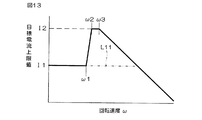
具体的には、センサ故障判定部25によってレゾルバ2の故障が生じたと判定されると、制限部33の働きによって目標電流値の上限値(以下、「目標電流上限値」という。)が図13に示すように制限される。モータ1の回転速度ωが所定の閾値ω1以下の低速領域において、目標電流上限値が、第1上限値I1に制限される。閾値ω1よりも大きな閾値ω2以上の高速領域においては、目標電流上限値は、第1上限値I1よりも大きな第2上限値I2とされている。ただし、閾値ω2よりも大きな所定速度ω3以上の回転速度領域では、モータ1の逆起電力のためにモータ電流が低下するので、それに応じて、回転速度ωの増加に伴ってリニアに減少する特性で目標電流上限値が定められており、この特性に従って基本目標電流値演算部15における基本目標電流値I*の設定が行われる。
Therefore, in this reference embodiment, when a failure occurs in the resolver 2 and the rotor position estimation is performed by the position estimation unit 60, the target current value is set in the low rotation speed region where the position estimation by the low speed region position estimation unit 61 is performed. I try to limit it.
Specifically, when it is determined by the sensor failure determination unit 25 that the resolver 2 has failed, the upper limit value of the target current value (hereinafter referred to as “target current upper limit value”) is acted by the function of the limiting unit 33 as shown in FIG. As shown in In the low speed region where the rotational speed ω of the motor 1 is equal to or lower than the predetermined threshold ω1, the target current upper limit value is limited to the first upper limit value I1. In a high-speed region that is greater than or equal to the threshold value ω2 that is greater than the threshold value ω1, the target current upper limit value is a second upper limit value I2 that is greater than the first upper limit value I1. However, in the rotational speed region of the predetermined speed ω3 that is greater than the threshold ω2 and higher than the threshold speed ω2, the motor current decreases due to the counter electromotive force of the motor 1, and accordingly, the characteristic that linearly decreases as the rotational speed ω increases. The basic target current value I * is set in the basic target current value calculation unit 15 according to this characteristic.

閾値ω1,ω2の間の遷移領域では、回転速度ωの増加に伴って、第1上限値I1から第2上限値I2までリニアに増加するように、目標電流上限値が定められる。制限部33は、閾値ω2以下の回転速度領域において、通常時(図13の破線参照)よりも低い目標電流上限値を定めるものである。
たとえば、閾値ω1以下の低速領域におけるロータ位置の推定は低速域用位置推定部61によって行われ、閾値ω2を超える速度領域(中・高速領域)におけるロータ位置の推定は、高速域用位置推定部62によって行われる。
In the transition region between the threshold values ω1 and ω2, the target current upper limit value is determined so as to increase linearly from the first upper limit value I1 to the second upper limit value I2 as the rotational speed ω increases. The limiting unit 33 determines a target current upper limit value lower than that in the normal state (see the broken line in FIG. 13) in the rotation speed region below the threshold ω2.
For example, the estimation of the rotor position in the low speed region below the threshold value ω1 is performed by the low speed region position estimation unit 61, and the estimation of the rotor position in the speed region (medium / high speed region) exceeding the threshold value ω2 is performed. 62.

したがって、低速域用位置推定部61による位置推定が行われるときには、目標電流上限値が第1上限値I1とされる。これにより、モータ電流の応答からセンシング信号成分を効率的に抽出することができる状態に維持することができるから、低速域における位置推定精度を確保することができる。
レゾルバ2に故障が生じていない通常時には、閾値ω2以下の領域の目標電流上限値は、図13において破線で示すように第2上限値I2に定められる。すなわち、制限部33による制限は行われず、基本目標電流値演算部15は、第2上限値I2を上限として基本目標電流値I*を定める。
Accordingly, when position estimation is performed by the low speed range position estimation unit 61, the target current upper limit value is set to the first upper limit value I1. As a result, it is possible to maintain a state in which the sensing signal component can be efficiently extracted from the response of the motor current, and therefore it is possible to ensure position estimation accuracy in the low speed region.
At normal times when the resolver 2 has not failed, the target current upper limit value in the region below the threshold ω2 is set to the second upper limit value I2 as indicated by a broken line in FIG. That is, the restriction by the restriction unit 33 is not performed, and the basic target current value calculation unit 15 determines the basic target current value I * with the second upper limit value I2 as an upper limit.

なお、制限部33による目標電流上限値の制限は、図13において二点鎖線L11で示す特性に従って行われてもよい。すなわち、目標電流上限値をいずれの回転速度においても第1上限値I1以下に制限するようにしてもよい。
図14は、マイクロコンピュータ12Aが所定の制御周期毎に繰り返し実行する処理を説明するためのフローチャートである。マイクロコンピュータ12Aは、トルクセンサ7、車速センサ8、レゾルバ2、および電流検出部11の各出力信号を取り込む(ステップS11)。基本目標電流値演算部15は、トルクセンサ7が検出した操作トルクおよび車速センサ8が検出した車速に基づいて、基本目標電流値I*を演算する(ステップS12)。一方、センサ故障判定部25は、信号線2aに導出される信号に基づいて、レゾルバ2の故障の有無を判定する(ステップS13)。
Note that the limitation of the target current upper limit value by the limiting unit 33 may be performed according to the characteristics indicated by the two-dot chain line L11 in FIG. That is, the target current upper limit value may be limited to the first upper limit value I1 or less at any rotational speed.
FIG. 14 is a flowchart for explaining processing that the microcomputer 12A repeatedly executes at predetermined control cycles. The microcomputer 12A takes in the output signals of the torque sensor 7, the vehicle speed sensor 8, the resolver 2, and the current detection unit 11 (step S11). The basic target current value calculation unit 15 calculates the basic target current value I * based on the operation torque detected by the torque sensor 7 and the vehicle speed detected by the vehicle speed sensor 8 (step S12). On the other hand, the sensor failure determination unit 25 determines the presence or absence of a failure of the resolver 2 based on the signal derived to the signal line 2a (step S13).

レゾルバ2に故障がなければ(ステップS13:NO)、切換え部66によって、位置算出部22が算出する制御回転位置θ^(レゾルバ出力による制御回転位置)が選択されて(ステップS14)、レゾルバ2の出力信号を用いながら基本目標電流値I*に基づいてモータ1を駆動する通常の制御が実行される(ステップS15)。より具体的には、dq軸目標電流値演算部16によってd軸目標電流値Id *およびq軸目標電流値Iq *が設定される。また、電流検出部11が検出する相電流Iuvwが、座標変換部17A,17Bで座標変換され、γ軸電流Iγおよびδ軸電流Iδが求められる。偏差演算部18は、d軸電流偏差δId(=Id *−Iγ)およびq軸電流偏差δIq(=Iq *−Iδ)を求める。PI制御部19Aは、電流偏差δId,δIqに対するPI(比例積分)演算等を行い、このPI演算に基づいて、電圧指令値生成部19Bによって、d軸電圧指令値Vd *およびq軸電圧指令値Vq *が生成される。これらが座標変換部20A,20Bにおいて座標変換されることによって、UVW相の電圧指令値Vu *,Vv *,Vw *が生成される。これらの電圧指令値Vu *,Vv *,Vw *に対応するPWM制御信号がPWM制御部21によって生成される。αβ/γδ座標変換部17Bおよびγδ/αβ座標変換部20Aにおける座標変換演算には、レゾルバ2の出力信号に基づいて位置算出部22によって算出される制御回転位置θ^が用いられる(ステップS14)。 If there is no failure in the resolver 2 (step S13: NO), the switching unit 66 selects the control rotation position θ ^ (control rotation position based on the resolver output) calculated by the position calculation unit 22 (step S14). The normal control for driving the motor 1 is executed based on the basic target current value I * using the output signal (step S15). More specifically, the d-axis target current value I d * and the q-axis target current value I q * are set by the dq-axis target current value calculation unit 16. Further, the phase current I uvw detected by the current detection unit 11 is subjected to coordinate conversion by the coordinate conversion units 17A and 17B, and the γ-axis current I γ and the δ-axis current I δ are obtained. The deviation calculation unit 18 calculates a d-axis current deviation δI d (= I d * −I γ ) and a q-axis current deviation δI q (= I q * −I δ ). The PI control unit 19A performs a PI (proportional integration) calculation or the like on the current deviations δI d and δI q , and based on this PI calculation, the voltage command value generation unit 19B performs the d-axis voltage command value V d * and the q-axis. A voltage command value V q * is generated. These are subjected to coordinate conversion by the coordinate conversion units 20A and 20B, thereby generating UVW phase voltage command values V u * , V v * and V w * . A PWM control signal corresponding to these voltage command values V u * , V v * , V w * is generated by the PWM control unit 21. For the coordinate conversion calculation in the αβ / γδ coordinate conversion unit 17B and the γδ / αβ coordinate conversion unit 20A, the control rotational position θ ^ calculated by the position calculation unit 22 based on the output signal of the resolver 2 is used (step S14). .

一方、センサ故障判定部25によって、レゾルバ2に故障が生じていると判定されると(ステップS13:YES)、切換え部66によって、位置推定部60が演算する制御回転位置θ^(推定回転位置)が選択され(ステップS16)、さらに、制限部33による制限処理が行われる(ステップS17,S18)。すなわち、基本目標電流値演算部15によって演算された基本目標電流値I*が目標電流上限値(図13参照。回転速度ωに応じた値)以上かどうかが判断される(ステップS17)。基本目標電流値I*が目標電流上限値未満であれば(ステップS17:NO)、基本目標電流値I*をそのまま用いる。すなわち、位置推定部60が演算する制御回転位置θ^を用いつつ、基本目標電流値I*に基づいてモータ1が制御される(ステップS15)。これに対して、基本目標電流値I*が目標電流上限値以上であるときには(ステップS17:YES)、制限部33の働きによって、基本目標電流値I*に目標電流上限値が代入される(ステップS18)。したがって、目標電流上限値に基づいて、位置推定部60が演算する制御回転位置θ^を用いつつ、モータ1が制御される。 On the other hand, when the sensor failure determination unit 25 determines that the resolver 2 has a failure (step S13: YES), the switching unit 66 calculates the control rotation position θ ^ (estimated rotation position) calculated by the position estimation unit 60. ) Is selected (step S16), and restriction processing by the restriction unit 33 is further performed (steps S17 and S18). That is, it is determined whether or not the basic target current value I * calculated by the basic target current value calculation unit 15 is equal to or greater than the target current upper limit value (see FIG. 13, a value corresponding to the rotational speed ω) (step S17). If the basic target current value I * is less than the target current upper limit value (step S17: NO), the basic target current value I * is used as it is. That is, the motor 1 is controlled based on the basic target current value I * while using the control rotation position θ ^ calculated by the position estimation unit 60 (step S15). On the other hand, when the basic target current value I * is greater than or equal to the target current upper limit value (step S17: YES), the target current upper limit value is substituted into the basic target current value I * by the action of the limiting unit 33 ( Step S18). Therefore, based on the target current upper limit value, the motor 1 is controlled using the control rotation position θ ^ calculated by the position estimation unit 60.

位置推定部60の推定位置切換え部63は、回転速度演算部23が求めるモータ回転速度ωが閾値ω1以下のときには、推定位置切換え部63は、低速域用位置推定部61によって推定された低速推定回転位置θLを出力する。また、モータ回転速度が閾値ω1を超えているときには、推定位置切換え部63は、高速域用位置推定部62よって推定された高速推定回転位置θHを出力する。 The estimated position switching unit 63 of the position estimating unit 60 determines that the estimated position switching unit 63 estimates the low speed estimated by the low speed range position estimating unit 61 when the motor rotational speed ω obtained by the rotational speed calculating unit 23 is equal to or less than the threshold ω1. The rotational position θ L is output. When the motor rotation speed exceeds the threshold value ω1, the estimated position switching unit 63 outputs the high-speed estimated rotation position θ H estimated by the high-speed range position estimating unit 62.

このように、この参考形態では、レゾルバ2に故障が発生したときには、位置推定部60によって求められる推定回転位置を制御回転位置θ^として用いたセンサレス制御(レゾルバ2の出力信号を用いずに行うモータ制御)に切り換えられる。これにより、レゾルバ2が故障した後にも、モータ1の駆動を継続でき、操舵補助力を舵取り機構3に与えることができる。また、センサレス制御が行われる場合において、低速域用位置推定部61によってロータ回転位置の推定が行われる低速域では、目標電流上限値が、一定以上のロータ位置推定精度が得られる値I1に制限されるようになっている。これにより、低速域においても、ロータ回転位置を精度よく推定することができるので、モータ1をスムーズに回転させることができる。これにより、良好な操舵フィーリングを実現できる。 As described above, in this reference embodiment, when a failure occurs in the resolver 2, sensorless control using the estimated rotational position obtained by the position estimating unit 60 as the control rotational position θ ^ is performed without using the output signal of the resolver 2. Switch to motor control. Thereby, even after the resolver 2 breaks down, the drive of the motor 1 can be continued and the steering assist force can be applied to the steering mechanism 3. In addition, when sensorless control is performed, the target current upper limit value is limited to a value I1 that provides a certain or higher rotor position estimation accuracy in the low speed range where the rotor rotational position is estimated by the low speed range position estimation unit 61. It has come to be. Thereby, since the rotor rotational position can be accurately estimated even in the low speed region, the motor 1 can be smoothly rotated. Thereby, a favorable steering feeling can be realized.

低速域用位置推定部61によるロータ回転位置の推定には、ある程度の時間が必要である。すなわち、低速域用位置推定部61を用いたセンサレス制御のためには、センシング信号発生部65からセンシング信号を発生させ、それに対するモータ電流の応答を検出し、それに基づいてロータ回転位置を演算する一連の処理が必要となる。これらの処理のために、制御開始初期には、位置不定期間が生じる。この問題は、レゾルバ2の故障が検出されてセンサレス制御に移行した直後の期間において、その直前にレゾルバ2の出力信号から得られた制御回転位置θ^を、センサレス制御のための初期値として用いることによって解決できる。   A certain amount of time is required for the estimation of the rotor rotational position by the low-speed range position estimation unit 61. That is, for sensorless control using the low-speed range position estimation unit 61, a sensing signal is generated from the sensing signal generation unit 65, a response of the motor current to the detection signal is detected, and the rotor rotational position is calculated based thereon. A series of processing is required. Because of these processes, a position indefinite period occurs at the beginning of control. This problem is that the control rotational position θ ^ obtained from the output signal of the resolver 2 immediately before that is used as the initial value for the sensorless control in the period immediately after the failure of the resolver 2 is detected and shifts to the sensorless control. Can be solved.

高速域用位置推定部62による位置推定処理では、モータ1の誘起電圧を用いているので、速やかにロータ回転位置を推定できる。したがって、センサレス制御に移行した直後におけるロータ回転速度ωが閾値ω1以下の場合(低速域用位置推定部61による演算が行われる場合)に限って、レゾルバ2の出力に基づいて最後(故障判定直前)に演算された制御回転位置θ^をセンサレス制御の初期値として用いることとしてもよい。   Since the induced voltage of the motor 1 is used in the position estimation process by the high speed range position estimation unit 62, the rotor rotational position can be estimated quickly. Therefore, only when the rotor rotational speed ω immediately after the shift to the sensorless control is equal to or less than the threshold ω1 (when the calculation by the low-speed range position estimation unit 61 is performed), based on the output of the resolver 2 (just before the failure determination). The control rotation position θ ^ calculated in () may be used as an initial value for sensorless control.

図15は、さらに他の参考形態に係るモータ制御装置を適用した電動パワーステアリング装置の電気的構成を説明するためのブロック図である。この図15において、前述の図7に示された各部に対応する部分には、同一の参照符号を付して示す。
この参考形態では、位置推定部60Aには、低速域用位置推定部が備えられておらず、誘起電圧に基づいてロータ回転位置を推定する高速域用位置推定部62だけが備えられている。また、レゾルバ2の故障時の制御態様を定めるための制御則決定器80が備えられている。
FIG. 15 is a block diagram for explaining an electrical configuration of an electric power steering apparatus to which a motor control apparatus according to still another reference embodiment is applied. In FIG. 15, parts corresponding to those shown in FIG. 7 are given the same reference numerals.
In this reference embodiment, the position estimation unit 60A is not provided with the low speed region position estimation unit, and is provided with only the high speed region position estimation unit 62 that estimates the rotor rotational position based on the induced voltage. Further, a control law determiner 80 is provided for determining a control mode when the resolver 2 fails.

ロータが停止しているか、またはロータ回転速度が低い場合には、誘起電圧が小さいので、ロータ位置を推定することができない。そこで、この参考形態では、誘起電圧が小さいときには、目標電流値をゼロとし、ステアリングホイールの回転によってモータ1から誘起電圧が発生したときに、この誘起電圧に基づいてロータ回転位置を推定するようにしている。 When the rotor is stopped or the rotor rotational speed is low, the induced voltage is small, so the rotor position cannot be estimated. Therefore, in this reference embodiment, when the induced voltage is small, the target current value is set to zero, and when the induced voltage is generated from the motor 1 by the rotation of the steering wheel, the rotor rotational position is estimated based on the induced voltage. ing.

図16は、マイクロコンピュータ12Aの働きを説明するためのフローチャートである。この図16において、前述の図14に示された各ステップと同様の処理が行われるステップは、図14中の符号と同符号を付して示す。
マイクロコンピュータ12Aは、トルクセンサ7、車速センサ8、レゾルバ2、および電流検出部11の各出力信号を取り込む(ステップS11)。基本目標電流値演算部15は、トルクセンサ7が検出した操作トルクおよび車速センサ8が検出した車速に基づいて、基本目標電流値I*を演算する(ステップS12)。一方、センサ故障判定部25は、信号線2aに導出される信号に基づいて、レゾルバ2の故障の有無を判定する(ステップS13)。
FIG. 16 is a flowchart for explaining the operation of the microcomputer 12A. In FIG. 16, steps in which processing similar to the steps shown in FIG. 14 is performed are denoted by the same reference numerals as those in FIG. 14.
The microcomputer 12A takes in the output signals of the torque sensor 7, the vehicle speed sensor 8, the resolver 2, and the current detection unit 11 (step S11). The basic target current value calculation unit 15 calculates the basic target current value I * based on the operation torque detected by the torque sensor 7 and the vehicle speed detected by the vehicle speed sensor 8 (step S12). On the other hand, the sensor failure determination unit 25 determines the presence or absence of a failure of the resolver 2 based on the signal derived to the signal line 2a (step S13).

レゾルバ2に故障のない通常時には(ステップS13:NO)、レゾルバ2の出力信号を用いて位置算出部22が演算する制御回転位置θ^が切換え部66によって選択される(ステップS14)。そして、この制御回転位置θ^を用いつつ基本目標電流値I*に基づいて、モータ1の制御が実行される(ステップS15)。
一方、センサ故障判定部25によって、レゾルバ2に故障が生じていると判定されると(ステップS13:YES)、切換え部66は、位置推定部60Aの推定演算によって求められる制御回転位置θ^(推定回転位置)を選択する(ステップS16)。
At normal time when the resolver 2 has no failure (step S13: NO), the control rotational position θ ^ calculated by the position calculation unit 22 using the output signal of the resolver 2 is selected by the switching unit 66 (step S14). Then, the control of the motor 1 is executed based on the basic target current value I * using the control rotational position θ ^ (step S15).
On the other hand, when the sensor failure determination unit 25 determines that a failure has occurred in the resolver 2 (step S13: YES), the switching unit 66 determines the control rotational position θ ^ ( (Estimated rotational position) is selected (step S16).

また、制御則決定器80は、基本目標電流値演算部15から生成される基本目標電流値I*をゼロとする(ステップS20)。これにより、電圧指令値Vu *,Vv *,Vw *は、モータ1の誘起電圧に等しくなる。そこで、制御則決定器80は、電圧指令値Vu *,Vv *,Vw *(誘起電圧)からモータ1の誘起電圧を求める(ステップS21)。そして、制御則決定器80は、求めた誘起電圧を所定の閾値Vthと比較する(ステップS22)。この閾値Vthは、外乱オブザーバ75(図11参照)による誘起電圧の推定が可能な下限値に近い値とされる。 Further, the control law determiner 80 sets the basic target current value I * generated from the basic target current value calculation unit 15 to zero (step S20). As a result, the voltage command values V u * , V v * , and V w * are equal to the induced voltage of the motor 1. Therefore, the control law determiner 80 obtains the induced voltage of the motor 1 from the voltage command values V u * , V v * , V w * (induced voltage) (step S21). Then, the control law determiner 80 compares the obtained induced voltage with a predetermined threshold value V th (step S22). This threshold value V th is a value close to the lower limit value at which the induced voltage can be estimated by the disturbance observer 75 (see FIG. 11).

誘起電圧が閾値Vthよりも大きいときには(ステップS22:YES)、制御則決定器80は、高速域用位置推定部62によってロータ回転位置の推定を行わせるとともに(ステップS23)、基本目標電流値演算部15には、操作トルクおよび車速に応じた基本目標電流値I*を演算させる(ステップS24)。この演算を省いて、ステップS12で求めた基本目標電流値I*をそのまま用いてもよい。こうして求められた基本目標電流値I*に基づいて、高速域用位置推定部62によって演算された制御回転位置θ^を用いつつ、モータ1の制御が行われる(ステップS15)。 When the induced voltage is larger than the threshold value V th (step S22: YES), the control law determiner 80 causes the high-speed region position estimation unit 62 to estimate the rotor rotational position (step S23), and the basic target current value. The calculation unit 15 is caused to calculate a basic target current value I * corresponding to the operation torque and the vehicle speed (step S24). This calculation may be omitted, and the basic target current value I * obtained in step S12 may be used as it is. Based on the basic target current value I * thus obtained, the motor 1 is controlled using the control rotational position θ ^ calculated by the high speed range position estimation unit 62 (step S15).

誘起電圧が閾値Vth以下のときには(ステップS22:NO)、高速域用位置推定部62によるロータ回転位置推定演算は行われず、基本目標電流値I*がゼロに維持される。すなわち、基本目標電流値I*をゼロとした状態で、モータ1の駆動が行われる(ステップS15)。これにより、モータ1が操舵抵抗となることを回避できる。
基本目標電流値I*がゼロに維持されている状態でステアリングホイールが操作されると、モータ1が外力によって回転される結果、誘起電圧が生じる。この誘起電圧が閾値Vthを超えると(ステップS22:YES)、高速域用位置推定部62によって制御回転位置θ^が演算され(ステップS23)、この演算された制御回転位置θ^に基づいてモータ1が駆動されることになる(ステップS15)。このとき、基本目標電流値I*は、操作トルクおよび車速に応じた有意値に設定される(ステップS24)。
When the induced voltage is less than or equal to the threshold V th (step S22: NO), the rotor rotational position estimation calculation by the high speed region position estimating unit 62 is not performed, and the basic target current value I * is maintained at zero. That is, the motor 1 is driven with the basic target current value I * set to zero (step S15). Thereby, it can avoid that the motor 1 becomes steering resistance.
When the steering wheel is operated while the basic target current value I * is maintained at zero, an induced voltage is generated as a result of the motor 1 being rotated by an external force. When the induced voltage exceeds the threshold value V th (step S22: YES), the high speed region position estimation unit 62 calculates the control rotation position θ ^ (step S23), and based on the calculated control rotation position θ ^. The motor 1 is driven (step S15). At this time, the basic target current value I * is set to a significant value corresponding to the operation torque and the vehicle speed (step S24).

このようにして、この参考形態によれば、レゾルバ2が故障した後でも、高速域用位置推定部62による位置推定が可能な大きさの誘起電圧が生じている限りにおいて、モータ1を駆動することができ、舵取り機構3に対して操舵補助力を与えることができる。
以上、この発明の実施形態および参考形態について説明したが、さらに他の形態で実施も可能である。たとえば、前述の図7参考態では、基本目標電流値を制限するようにしているが、モータ1に供給される実電流を制限するようにしても同様の効果が得られる。
Thus, according to this reference embodiment, even after the resolver 2 has failed, to the extent that the induced voltage of the position estimation can be sized according to the high speed region for the position estimator 62 is caused to drive the motor 1 And a steering assist force can be applied to the steering mechanism 3.
Having described implementation form and reference embodiment of the present invention, it is also possible implementation in other forms further. For example, in the reference shape state of FIG. 7 described above, but so as to limit the basic target current value, the same effect can be obtained so as to limit the actual current supplied to the motor 1.

また、前述の図7参考形態において、センシング信号が三相電圧指令値VUVWに重畳しているが、電圧指令値生成部19Bが生成する電圧指令値Vγδまたはγδ/αβ座標変換部20Aが生成する二相電圧指令値Vαβにセンシング信号を重畳する構成としてもよい。
さらにまた、前述の実施形態および参考形態では、電動パワーステアリング装置の駆動源としてのモータ1を制御する場合について説明したが、前述の参考形態は、電動パワーステアリング装置以外の用途のモータ制御にも適用することができる。
Further, in the reference form of FIG. 7 described above, the sensing signal is superimposed on the three-phase voltage command value V UVW , but the voltage command value V γδ or γδ / αβ coordinate conversion unit 20A generated by the voltage command value generation unit 19B. The sensing signal may be superposed on the two-phase voltage command value V αβ generated by.
Furthermore, in the embodiment and reference embodiment described above has described the case that control the motor 1 as a drive source of an electric power steering apparatus, reference embodiment described above, the application of the motor control other than the electric power steering device It can also be applied to.

その他、特許請求の範囲に記載された事項の範囲で種々の設計変更を施すことが可能である。   In addition, various design changes can be made within the scope of matters described in the claims.

この発明の実施形態に係るモータ制御装置を適用した電動パワーステアリング装置の電気的構成を説明するためのブロック図である。 1 is a block diagram for explaining an electrical configuration of an electric power steering apparatus to which a motor control device according to an embodiment of the present invention is applied. FIG. モータの構成、ならびに高周波電圧ベクトルおよび電流ベクトルの回転を説明するための図である。It is a figure for demonstrating the structure of a motor, and rotation of a high frequency voltage vector and an electric current vector. 駆動回路の構成を説明するための電気回路図である。It is an electric circuit diagram for demonstrating the structure of a drive circuit. 図4Aおよび図4Bは、通電パターン駆動部が生成する制御信号の一例を示す波形図である。4A and 4B are waveform diagrams illustrating an example of a control signal generated by the energization pattern driving unit. 記実施形態の動作を説明するためのフローチャートである。It is a flowchart for explaining the operation before you facilities embodiment. 参考形態に係る電動パワーステアリング装置の電気的構成を示すブロック図である。It is a block diagram which shows the electric constitution of the electric power steering apparatus which concerns on a reference form. 他の参考形態に係るモータ制御装置を適用した電動パワーステアリング装置の電気的構成を説明するためのブロック図である。It is a block diagram for demonstrating the electric constitution of the electric power steering apparatus to which the motor control apparatus which concerns on another reference form is applied. 高周波電圧ベクトルの印加によるロータ位相角推定動作を説明するための図である。It is a figure for demonstrating the rotor phase angle estimation operation | movement by application of a high frequency voltage vector. 位置推定部の構成を説明するためのブロック図である。It is a block diagram for demonstrating the structure of a position estimation part. 低速域用位置推定部の構成例を説明するためのブロック図である。It is a block diagram for demonstrating the structural example of the position estimation part for low speed areas. 高速域用位置推定部の構成例を示すブロック図である。It is a block diagram which shows the structural example of the position estimation part for high speed areas. 外乱オブザーバおよびこれに関連する構成の一例を説明するためのブロック図である。It is a block diagram for demonstrating an example of a disturbance observer and the structure relevant to this. 基本目標電流値の制限を説明するための特性図である。It is a characteristic view for demonstrating the restriction | limiting of a basic target electric current value. 前記図7参考形態の動作を説明するためのフローチャートである。It is a flowchart for demonstrating operation | movement of the reference form of the said FIG . さらに他の参考形態に係るモータ制御装置を適用した電動パワーステアリング装置の電気的構成を説明するためのブロック図である。It is a block diagram for demonstrating the electrical structure of the electric power steering apparatus to which the motor control apparatus which concerns on another reference form is applied. 前記図15参考形態の動作を説明するためのフローチャートである。 16 is a flowchart for explaining the operation of the reference embodiment of FIG.

符号の説明Explanation of symbols

1…モータ、2…レゾルバ、10,10A…モータ制御装置、12,12A…マイクロコンピュータ、50…ロータ、55…ステータ   DESCRIPTION OF SYMBOLS 1 ... Motor, 2 ... Resolver 10, 10A ... Motor controller, 12, 12A ... Microcomputer, 50 ... Rotor, 55 ... Stator

Claims (1)

ロータと、このロータに対向するステータとを備えたモータを制御するためのモータ制御装置であって、
前記ロータの回転位置を検出する回転センサと、
この回転センサの正常時には当該回転センサの出力信号に基づいて前記モータを制御する一方で、前記回転センサの故障時には前記正常時の制御態様に対して制限を加えた制御態様で、前記回転センサの出力信号を用いずに、前記モータを制御する制御手段とを含み、
前記モータが、車両の舵取り機構に転舵力を付与する転舵用モータであり、
前記制御手段は、前記回転センサの故障時に、車両の操向のための操作部材に加えられる操作トルクが所定のトルク閾値以下であることを条件に、所定の通電パターンで前記モータを駆動するものであり、前記トルク閾値が前記所定の通電パターンで前記モータを駆動するときに脱調が生じるおそれのない範囲で可能な限り大きな値に定められている、モータ制御装置。
A motor control device for controlling a motor including a rotor and a stator facing the rotor,
A rotation sensor for detecting a rotation position of the rotor;
When the rotation sensor is normal, the motor is controlled based on the output signal of the rotation sensor. On the other hand, when the rotation sensor is out of order, the control mode is limited to the normal control mode. Control means for controlling the motor without using an output signal,
The motor is a steering motor that applies a steering force to a steering mechanism of a vehicle;
The control means drives the motor in a predetermined energization pattern on condition that an operation torque applied to an operation member for steering the vehicle is equal to or less than a predetermined torque threshold when the rotation sensor fails. der is, that have been established to a larger value as possible within a range with no possibility of step-out occurs when the torque threshold is to drive the motor at the predetermined energization pattern, the motor control device.
JP2008164560A 2008-06-24 2008-06-24 Motor control device Expired - Fee Related JP5273450B2 (en)

Priority Applications (1)

Application Number Priority Date Filing Date Title
JP2008164560A JP5273450B2 (en) 2008-06-24 2008-06-24 Motor control device

Applications Claiming Priority (1)

Application Number Priority Date Filing Date Title
JP2008164560A JP5273450B2 (en) 2008-06-24 2008-06-24 Motor control device

Related Child Applications (1)

Application Number Title Priority Date Filing Date
JP2012282985A Division JP5614598B2 (en) 2012-12-26 2012-12-26 Motor control device

Publications (3)

Publication Number Publication Date
JP2010011542A JP2010011542A (en) 2010-01-14
JP2010011542A5 JP2010011542A5 (en) 2012-01-26
JP5273450B2 true JP5273450B2 (en) 2013-08-28

Family

ID=41591357

Family Applications (1)

Application Number Title Priority Date Filing Date
JP2008164560A Expired - Fee Related JP5273450B2 (en) 2008-06-24 2008-06-24 Motor control device

Country Status (1)

Country Link
JP (1) JP5273450B2 (en)

Cited By (1)

* Cited by examiner, † Cited by third party
Publication number Priority date Publication date Assignee Title
CN110171470A (en) * 2014-09-10 2019-08-27 Trw有限公司 Motor drive circuit system

Families Citing this family (7)

* Cited by examiner, † Cited by third party
Publication number Priority date Publication date Assignee Title
JP5549541B2 (en) * 2010-10-28 2014-07-16 ダイキン工業株式会社 Rotor position detection method, motor control method, motor control device, and program
JP5867782B2 (en) * 2011-11-30 2016-02-24 株式会社ジェイテクト Vehicle steering system
JP5971512B2 (en) * 2011-12-02 2016-08-17 株式会社ジェイテクト Vehicle steering system
KR101397875B1 (en) * 2012-12-18 2014-05-20 삼성전기주식회사 Apparatus and method for motor drive control, and motor using the same
JP6863195B2 (en) * 2017-09-19 2021-04-21 トヨタ自動車株式会社 Drive device
JP7247152B2 (en) 2019-09-30 2023-03-28 ダイキン工業株式会社 Motor driving method and motor driving device
JP7086505B1 (en) 2021-03-29 2022-06-20 三菱電機株式会社 Control device for AC rotary electric machine

Family Cites Families (5)

* Cited by examiner, † Cited by third party
Publication number Priority date Publication date Assignee Title
JPH04312388A (en) * 1991-04-09 1992-11-04 Mitsubishi Electric Corp Drive controller for dc brushless motor
JPH1014300A (en) * 1996-06-17 1998-01-16 Meidensha Corp Control system-switching system
JP2001112282A (en) * 1999-10-01 2001-04-20 Matsushita Electric Ind Co Ltd Motor controller
JP2005253226A (en) * 2004-03-05 2005-09-15 Hitachi Ltd Control device of brushless motor for vehicle
JP2007269277A (en) * 2006-03-31 2007-10-18 Isuzu Motors Ltd Electric power steering device

Cited By (1)

* Cited by examiner, † Cited by third party
Publication number Priority date Publication date Assignee Title
CN110171470A (en) * 2014-09-10 2019-08-27 Trw有限公司 Motor drive circuit system

Also Published As

Publication number Publication date
JP2010011542A (en) 2010-01-14

Similar Documents

Publication Publication Date Title
JP5614598B2 (en) Motor control device
JP5273450B2 (en) Motor control device
JP5435252B2 (en) Vehicle steering system
JP5273451B2 (en) Motor control device
JP5168536B2 (en) Motor control device
JP5267848B2 (en) Motor control device
JP5252190B2 (en) Motor control device
JP2010029030A (en) Motor controller
JP2010029028A (en) Motor controller
JP2014204556A (en) Motor control device
JP5170505B2 (en) Motor control device
JP6939800B2 (en) Motor control method, motor control system and electric power steering system
JP5392530B2 (en) Motor control device
WO2018159101A1 (en) Motor control method, motor control system, and electric power steering system
JP2008236990A (en) Motor control apparatus
JP2010178609A (en) Motor control device
JP6394885B2 (en) Electric power steering device
WO2020080170A1 (en) Failure diagnosis method, power conversion device, motor module, and electric power steering device
WO2018159103A1 (en) Motor control method, motor control system, and electric power steering system
WO2018159104A1 (en) Motor control method, motor control system, and electric power steering system
JP2009100544A (en) Motor controller
WO2018159099A1 (en) Motor control method, motor control system, and electric power steering system
JP5327503B2 (en) Motor control device
JP2009261172A (en) Controller and motor controlling method
JP2009261102A (en) Motor controller

Legal Events

Date Code Title Description
A621 Written request for application examination

Free format text: JAPANESE INTERMEDIATE CODE: A621

Effective date: 20110221

A521 Written amendment

Free format text: JAPANESE INTERMEDIATE CODE: A523

Effective date: 20111025

A521 Written amendment

Free format text: JAPANESE INTERMEDIATE CODE: A523

Effective date: 20111202

A977 Report on retrieval

Free format text: JAPANESE INTERMEDIATE CODE: A971007

Effective date: 20121107

A131 Notification of reasons for refusal

Free format text: JAPANESE INTERMEDIATE CODE: A131

Effective date: 20121108

A521 Written amendment

Free format text: JAPANESE INTERMEDIATE CODE: A523

Effective date: 20121226

TRDD Decision of grant or rejection written
A01 Written decision to grant a patent or to grant a registration (utility model)

Free format text: JAPANESE INTERMEDIATE CODE: A01

Effective date: 20130418

A61 First payment of annual fees (during grant procedure)

Free format text: JAPANESE INTERMEDIATE CODE: A61

Effective date: 20130501

R150 Certificate of patent or registration of utility model

Free format text: JAPANESE INTERMEDIATE CODE: R150

Ref document number: 5273450

Country of ref document: JP

Free format text: JAPANESE INTERMEDIATE CODE: R150

LAPS Cancellation because of no payment of annual fees