JP5270165B2 - Control of adhesion of vaporized organic materials - Google Patents
Control of adhesion of vaporized organic materials Download PDFInfo
- Publication number
- JP5270165B2 JP5270165B2 JP2007540349A JP2007540349A JP5270165B2 JP 5270165 B2 JP5270165 B2 JP 5270165B2 JP 2007540349 A JP2007540349 A JP 2007540349A JP 2007540349 A JP2007540349 A JP 2007540349A JP 5270165 B2 JP5270165 B2 JP 5270165B2
- Authority
- JP
- Japan
- Prior art keywords
- organic material
- manifold
- temperature
- vaporized
- heating device
- Prior art date
- Legal status (The legal status is an assumption and is not a legal conclusion. Google has not performed a legal analysis and makes no representation as to the accuracy of the status listed.)
- Active
Links
Images


Classifications
-
- C—CHEMISTRY; METALLURGY
- C23—COATING METALLIC MATERIAL; COATING MATERIAL WITH METALLIC MATERIAL; CHEMICAL SURFACE TREATMENT; DIFFUSION TREATMENT OF METALLIC MATERIAL; COATING BY VACUUM EVAPORATION, BY SPUTTERING, BY ION IMPLANTATION OR BY CHEMICAL VAPOUR DEPOSITION, IN GENERAL; INHIBITING CORROSION OF METALLIC MATERIAL OR INCRUSTATION IN GENERAL
- C23C—COATING METALLIC MATERIAL; COATING MATERIAL WITH METALLIC MATERIAL; SURFACE TREATMENT OF METALLIC MATERIAL BY DIFFUSION INTO THE SURFACE, BY CHEMICAL CONVERSION OR SUBSTITUTION; COATING BY VACUUM EVAPORATION, BY SPUTTERING, BY ION IMPLANTATION OR BY CHEMICAL VAPOUR DEPOSITION, IN GENERAL
- C23C14/00—Coating by vacuum evaporation, by sputtering or by ion implantation of the coating forming material
- C23C14/22—Coating by vacuum evaporation, by sputtering or by ion implantation of the coating forming material characterised by the process of coating
- C23C14/54—Controlling or regulating the coating process
- C23C14/542—Controlling the film thickness or evaporation rate
-
- C—CHEMISTRY; METALLURGY
- C23—COATING METALLIC MATERIAL; COATING MATERIAL WITH METALLIC MATERIAL; CHEMICAL SURFACE TREATMENT; DIFFUSION TREATMENT OF METALLIC MATERIAL; COATING BY VACUUM EVAPORATION, BY SPUTTERING, BY ION IMPLANTATION OR BY CHEMICAL VAPOUR DEPOSITION, IN GENERAL; INHIBITING CORROSION OF METALLIC MATERIAL OR INCRUSTATION IN GENERAL
- C23C—COATING METALLIC MATERIAL; COATING MATERIAL WITH METALLIC MATERIAL; SURFACE TREATMENT OF METALLIC MATERIAL BY DIFFUSION INTO THE SURFACE, BY CHEMICAL CONVERSION OR SUBSTITUTION; COATING BY VACUUM EVAPORATION, BY SPUTTERING, BY ION IMPLANTATION OR BY CHEMICAL VAPOUR DEPOSITION, IN GENERAL
- C23C14/00—Coating by vacuum evaporation, by sputtering or by ion implantation of the coating forming material
- C23C14/06—Coating by vacuum evaporation, by sputtering or by ion implantation of the coating forming material characterised by the coating material
- C23C14/12—Organic material
-
- C—CHEMISTRY; METALLURGY
- C23—COATING METALLIC MATERIAL; COATING MATERIAL WITH METALLIC MATERIAL; CHEMICAL SURFACE TREATMENT; DIFFUSION TREATMENT OF METALLIC MATERIAL; COATING BY VACUUM EVAPORATION, BY SPUTTERING, BY ION IMPLANTATION OR BY CHEMICAL VAPOUR DEPOSITION, IN GENERAL; INHIBITING CORROSION OF METALLIC MATERIAL OR INCRUSTATION IN GENERAL
- C23C—COATING METALLIC MATERIAL; COATING MATERIAL WITH METALLIC MATERIAL; SURFACE TREATMENT OF METALLIC MATERIAL BY DIFFUSION INTO THE SURFACE, BY CHEMICAL CONVERSION OR SUBSTITUTION; COATING BY VACUUM EVAPORATION, BY SPUTTERING, BY ION IMPLANTATION OR BY CHEMICAL VAPOUR DEPOSITION, IN GENERAL
- C23C14/00—Coating by vacuum evaporation, by sputtering or by ion implantation of the coating forming material
- C23C14/22—Coating by vacuum evaporation, by sputtering or by ion implantation of the coating forming material characterised by the process of coating
- C23C14/24—Vacuum evaporation
-
- C—CHEMISTRY; METALLURGY
- C23—COATING METALLIC MATERIAL; COATING MATERIAL WITH METALLIC MATERIAL; CHEMICAL SURFACE TREATMENT; DIFFUSION TREATMENT OF METALLIC MATERIAL; COATING BY VACUUM EVAPORATION, BY SPUTTERING, BY ION IMPLANTATION OR BY CHEMICAL VAPOUR DEPOSITION, IN GENERAL; INHIBITING CORROSION OF METALLIC MATERIAL OR INCRUSTATION IN GENERAL
- C23C—COATING METALLIC MATERIAL; COATING MATERIAL WITH METALLIC MATERIAL; SURFACE TREATMENT OF METALLIC MATERIAL BY DIFFUSION INTO THE SURFACE, BY CHEMICAL CONVERSION OR SUBSTITUTION; COATING BY VACUUM EVAPORATION, BY SPUTTERING, BY ION IMPLANTATION OR BY CHEMICAL VAPOUR DEPOSITION, IN GENERAL
- C23C14/00—Coating by vacuum evaporation, by sputtering or by ion implantation of the coating forming material
- C23C14/22—Coating by vacuum evaporation, by sputtering or by ion implantation of the coating forming material characterised by the process of coating
- C23C14/54—Controlling or regulating the coating process
-
- H—ELECTRICITY
- H10—SEMICONDUCTOR DEVICES; ELECTRIC SOLID-STATE DEVICES NOT OTHERWISE PROVIDED FOR
- H10K—ORGANIC ELECTRIC SOLID-STATE DEVICES
- H10K50/00—Organic light-emitting devices
-
- H—ELECTRICITY
- H10—SEMICONDUCTOR DEVICES; ELECTRIC SOLID-STATE DEVICES NOT OTHERWISE PROVIDED FOR
- H10K—ORGANIC ELECTRIC SOLID-STATE DEVICES
- H10K71/00—Manufacture or treatment specially adapted for the organic devices covered by this subclass
-
- H—ELECTRICITY
- H10—SEMICONDUCTOR DEVICES; ELECTRIC SOLID-STATE DEVICES NOT OTHERWISE PROVIDED FOR
- H10K—ORGANIC ELECTRIC SOLID-STATE DEVICES
- H10K71/00—Manufacture or treatment specially adapted for the organic devices covered by this subclass
- H10K71/10—Deposition of organic active material
- H10K71/16—Deposition of organic active material using physical vapour deposition [PVD], e.g. vacuum deposition or sputtering
- H10K71/164—Deposition of organic active material using physical vapour deposition [PVD], e.g. vacuum deposition or sputtering using vacuum deposition
Description
本発明は、蒸発源の材料を、気化が起こって蒸気柱が発生する温度まで加熱することで基板の表面に薄膜を形成するという物理的な蒸着の分野に関する。 The present invention relates to the field of physical vapor deposition in which a thin film is formed on the surface of a substrate by heating the evaporation source material to a temperature at which vaporization occurs and vapor columns are generated.
真空環境中での物理的蒸着は、例えば小分子OLEDデバイスで用いられているような有機材料の薄膜を堆積させるのに一般に利用されている方法である。このような方法はよく知られており、例えばBarrのアメリカ合衆国特許第2,447,789号とTanabeらのヨーロッパ特許第0 982 411号に記載されている。有機材料は、速度に依存した望ましい気化温度またはそれに近い温度に長時間にわたって維持したとき、分解することがしばしばある。感受性のある有機材料をより高温にすると、分子構造が変化し、それに伴って材料の性質が変化する可能性がある。 Physical vapor deposition in a vacuum environment is a commonly used method for depositing thin films of organic materials, such as those used in small molecule OLED devices. Such methods are well known and are described, for example, in Barr U.S. Pat. No. 2,447,789 and Tanabe et al. European Patent No. 0 982 411. Organic materials often degrade when maintained at or near the desired vaporization temperature depending on the rate for an extended period of time. As sensitive organic materials are heated to higher temperatures, the molecular structure can change, and the properties of the material can change accordingly.
OLEDデバイスで使用される有機材料は、気化速度と蒸発源の温度の関係が比例状態から大きくはずれている。蒸発源の温度がわずかに変化すると、気化速度が非常に大きく変化する。それにもかかわらず従来の装置では、蒸発源の温度を、気化速度を制御するための唯一の手段として利用している。温度をうまく制御するため、従来の蒸発源では、よく断熱された熱伝導率の大きい材料で構成されていて固体部の体積が有機装填物の体積よりもはるかに大きい加熱構造が一般に利用されている。大きな熱伝導率によって構造全体の温度がうまく一様になり、大きな熱質量が、温度のゆらぎを小さくして温度を極めて小さな範囲内に維持することを助ける。このような方法により、定常状態での気化速度の安定性に関しては望ましい効果がもたらされたが、作動時に好ましくないことが起こる。このような装置は、スイッチを入れてから長時間(例えば2〜12時間)にわたって作動させた後に安定状態の温度分布になり、したがって安定な気化速度が実現されるのが一般的である。また、このような装置は、冷却にも長時間かかるため、かなりの量の有機材料(その中には高価だったり合成が難しかったりするものがある)が失われる可能性があるのが一般的である。さらに、材料が蒸発源から消費されるにつれて安定な状態はゆっくりとドリフトするため、一定の蒸発速度を維持するには入力する電力を変化させ(て温度分布を変え)る必要がある。 In organic materials used in OLED devices, the relationship between the vaporization rate and the temperature of the evaporation source deviates significantly from the proportional state. When the temperature of the evaporation source changes slightly, the vaporization rate changes very greatly. Nevertheless, conventional devices utilize the temperature of the evaporation source as the only means for controlling the vaporization rate. In order to control the temperature well, conventional evaporation sources generally use heating structures that are made of well-insulated materials with high thermal conductivity and the volume of the solid part is much larger than the volume of the organic charge. Yes. The large thermal conductivity provides a uniform temperature throughout the structure, and the large thermal mass helps to keep temperature within a very small range by reducing temperature fluctuations. Such a method has the desired effect on the stability of the vaporization rate in the steady state, but it is not desirable during operation. Such devices generally have a stable temperature distribution after being operated for a long time (eg 2 to 12 hours) after being switched on, and thus a stable vaporization rate is generally achieved. Also, such devices take a long time to cool, so it is common to lose a significant amount of organic material (some of which are expensive or difficult to synthesize). It is. Furthermore, since the stable state slowly drifts as the material is consumed from the evaporation source, it is necessary to change the input power (and change the temperature distribution) in order to maintain a constant evaporation rate.
材料を収容した蒸発源の始動と冷却の時間をできるだけ短くすることによって材料が高温になる時間をできるだけ短くするとともに、機械の作動時間をできるだけ長くするための現在の方法では、同じ材料を収容した複数の蒸発源を順番に使用する必要がある。例えば1つの蒸発源を8日間連続的に使用するのではなく、始動時間と冷却時間が重なるようにしながら2つの蒸発源をそれぞれ4日ずつ使用するか、8つの蒸発源をそれぞれ1日ずつ順番に使用することができる。しかし同じ蒸発源が複数あると、特に蒸発源の数が多い場合や、材料の数が多くて複数の蒸発源が必要な場合には、装置のサイズとコストが増大する。 The current method for minimizing the time for the material to become hot by minimizing the start-up and cooling time of the evaporation source containing the material as much as possible and for the longest possible machine operation time accommodates the same material It is necessary to use a plurality of evaporation sources in order. For example, instead of using one evaporation source continuously for 8 days, use two evaporation sources for 4 days each, with the start-up time and cooling time overlapping, or 8 evaporation sources for each day in turn. Can be used for However, when there are a plurality of the same evaporation sources, especially when the number of evaporation sources is large or when the number of materials is large and a plurality of evaporation sources are required, the size and cost of the apparatus increase.
Forrestら(アメリカ合衆国特許第6,337,102 B1号)は、有機材料と有機前駆体を気化させ、それを基板が内部に配置された反応容器に供給する方法を開示している。固体または液体から発生した蒸気は、キャリヤ・ガスを使用して運ばれる。有機材料は、可能なあらゆる流速で入ってくるキャリヤ・ガスを飽和させるのに十分な一定の高温に保たれる。堆積速度は、キャリヤ・ガスの流速を調節することによって制御する。Forrestらは、彼らの発明の一実施態様において、基板を適度に大きな反応容器の中に配置しており、その中に入ってくる蒸気が混合され、基板上で反応したり基板上に凝縮したりする。彼らの発明の別の一実施態様は、大面積の基板をコーティングするため、そのようないくつかの堆積プロセスを互いに連続して実施する操作を含む用途に関する。Forrestらは、この実施態様に関し、ガス・マニホールド(明細書では“一列に並んだ複数の穴を有する中空チューブ”として定義されている)から供給されるガス・カーテンを利用し、基板が移動する方向と垂直な材料堆積連続ラインを形成することを開示している。 Forrest et al. (US Pat. No. 6,337,102 B1) discloses a method of vaporizing an organic material and an organic precursor and supplying it to a reaction vessel having a substrate disposed therein. Vapor generated from a solid or liquid is carried using a carrier gas. The organic material is kept at a constant high temperature sufficient to saturate the incoming carrier gas at any possible flow rate. The deposition rate is controlled by adjusting the flow rate of the carrier gas. Forrest et al., In one embodiment of their invention, the substrate is placed in a reasonably large reaction vessel, and the vapor entering it is mixed and reacts on the substrate or condenses on the substrate. Or Another embodiment of their invention relates to an application involving the operation of performing several such deposition processes in succession with each other to coat large area substrates. Forrest et al., For this embodiment, use a gas curtain supplied from a gas manifold (defined herein as “hollow tube with a plurality of holes in a row”) to move the substrate. Forming a continuous line of material deposition perpendicular to the direction is disclosed.
Forrestらが開示している方法の大きな1つの問題は、厳密に温度制御された状態を維持するため、すべての材料が熱質量の大きなシステムの中で連続的に加熱されることである。このように長時間にわたって高温にさらされると、Barrの方法およびTanabeらの方法と同様、いくつかの材料は分解する可能性が大きくなる。Forrestらが開示している方法の別の問題は、システムの熱質量が大きくて、しかもキャリヤ・ガスを流し始める前にすべての材料が一様な温度になる必要があるため、材料を再装填するときの冷却と始動の時間が長いことである。 One major problem with the method disclosed by Forrest et al. Is that all materials are continuously heated in a system with a large thermal mass in order to remain strictly temperature controlled. When exposed to high temperatures for such an extended period of time, some materials, like Barr's method and Tanabe's method, are more likely to decompose. Another problem with the method disclosed by Forrest et al. Is that the thermal mass of the system is large and all materials need to be at a uniform temperature before the carrier gas begins to flow, so the material can be reloaded The time for cooling and starting is long.
従来技術では、情報表示学会2002国際シンポジウム、SIDダイジェスト02、891〜893ページの論文に記載されているアプライド・フィルムズ社のHoffmanらによるシステムも知られている。このシステムは、BarrとTanabeらが使用しているのと似たタイプの加熱された大きな遠隔蒸発源を、材料の蒸気を分配するためのマニホールドと組み合わせたものである。このシステムは、長時間にわたって高温にさらされることと、加熱システムの熱質量が大きいために冷却と始動の時間が長いことが原因で、材料の分解に関し、Barrの方法、Tanabeらの方法、Forrestらの方法と同じ問題を抱えている。 In the prior art, a system by Hoffman et al. Of Applied Films, which is described in a paper on Information Display Society 2002 International Symposium, SID Digest 02, pages 891-893, is also known. This system combines a large heated remote evaporation source of the type similar to that used by Barr and Tanabe et al. With a manifold for distributing the vapor of material. The system is subject to Barr's method, Tanabe et al., Forrest for material decomposition due to prolonged exposure to high temperatures and long heating and cooling time due to the large thermal mass of the heating system. I have the same problem as these methods.
ForrestらとHoffmanらが開示しているような蒸気供給法は、装置内の蒸着領域外で、より一般には蒸着チェンバー外で材料が蒸気に変換される“遠隔気化”として特徴づけられる。有機蒸気は、単独で、またはキャリヤ・ガスとともに蒸着チェンバーに導入され、最終的に基板の表面に到達する。この方法を利用するときには、供給ラインにおける望ましくない凝縮を避けるため、適切な加熱法を利用して細心の注意を払う必要がある。この問題は、無機材料を使用して実質的により高温で望む量を気化させることを考えるとき、より一層重要になる。さらに、広い面積に一様にコーティングするため気化した材料を供給するには、ガス・マニホールドを使用する必要がある。 The vapor delivery method as disclosed by Forrest et al. And Hoffman et al. Is characterized as “remote vaporization” where material is converted to vapor outside the vapor deposition zone within the apparatus, and more generally outside the vapor deposition chamber. Organic vapor alone or with a carrier gas is introduced into the deposition chamber and finally reaches the surface of the substrate. When using this method, care must be taken using appropriate heating methods to avoid undesired condensation in the supply line. This problem becomes even more important when considering the use of inorganic materials to vaporize the desired amount at substantially higher temperatures. In addition, a gas manifold must be used to supply vaporized material for uniform coating over a large area.
現在の遠隔気化法は、材料が長時間にわたって高温にさらされるという問題と、熱質量が大きな加熱システムであることが原因で始動と冷却に時間がかかるという問題を抱えている。しかしこのようなシステムは、BarrやTanaberaの方法と比べてコーティングの一様性と瞬間的な堆積速度の制御に関して優れた点をいくつか有する。これらの遠隔気化法では、例えばForrestらの方法だとキャリヤ・ガスのためのバルブを閉めることによって、Hoffmanらの方法だと有機蒸気のためのバルブを閉めることによって堆積をかなり素早く停止させることが可能だが、バルブの下流の有機蒸気またはキャリヤ・ガスは、マニホールドの圧力が蒸着チェンバーの圧力に低下するまでマニホールドから流出し続けるであろう。同様に、この方法だと堆積をかなり素早く開始できるが、有機蒸気とキャリヤ・ガスは、マニホールドが安定な圧力になるまで安定な蒸着速度に到達することはなかろう。これは問題である。なぜなら、遠隔気化を、有機蒸気の流れを制御するための、やはりマニホールドから離れていてマニホールドと連続していない構造(例えばバルブ)と組み合わせているからである。この遠隔構造では、マニホールドの開口部を通過する有機蒸気を素早く制御することはできない。そのため堆積の開始と停止が遅れることになる。バルブが離れた位置にある遠隔気化システムでは、このシステムの大きな熱質量が原因で、装填された新鮮な材料の加熱開始と冷却に時間がかかるという重要な課題を解決できないし、このシステムでは長時間にわたって高温にさらされることによる材料の分解という大きな問題を解決することもできない。 Current remote vaporization methods suffer from the problem that materials are exposed to high temperatures for extended periods of time and the time to start and cool down due to the heating system having a large thermal mass. However, such systems have some advantages over coating uniformity and instantaneous deposition rate control compared to Barr and Tanabera methods. In these remote vaporization methods, the deposition can be stopped fairly quickly, for example by closing the valve for the carrier gas in the method of Forrest et al., And in the method of Hoffman et al. By closing the valve for organic vapor. Although possible, the organic vapor or carrier gas downstream of the valve will continue to flow out of the manifold until the pressure in the manifold drops to the pressure in the deposition chamber. Similarly, although this method can initiate deposition fairly quickly, organic vapor and carrier gas will not reach a stable deposition rate until the manifold is at a stable pressure. This is a problem. This is because remote vaporization is combined with a structure (eg, a valve) that is also remote from the manifold and not continuous with the manifold to control the flow of organic vapor. With this remote structure, the organic vapor passing through the manifold opening cannot be quickly controlled. Therefore, the start and stop of deposition are delayed. Remote vaporization systems with remote valves cannot solve the important issue of the time to start heating and cooling fresh material that is loaded due to the large thermal mass of the system. Nor can it solve the major problem of material degradation due to exposure to high temperatures over time.
Furukawaらは、未審査の日本国特開平9-219289に、フラッシュ蒸着法によって有機薄膜エレクトロルミネッセンス素子を形成する方法を開示している。この方法では素早い始動と停止が可能だが、Furukawaらが述べているように、連続プロセスとして運転することはできない。有機材料は、加熱したプレートの上に落ちる。Furukawaは、粉末供給システムの性質や、いかにして実際に望む量の粉末を加熱したプレートの上に落とすかに関しては何も述べていないため、気化速度、堆積された膜の厚さ、厚さの一様性をいかにして制御するかがわからない。また、発生した直後の蒸気の凝縮温度よりも低い温度の粉末供給システムが冷たい指状突起部として作用し、発生した直後の蒸気の一部がその表面に凝縮することをいかにして回避するかも明確ではない。 Furukawa et al. Discloses a method for forming an organic thin film electroluminescent element by flash vapor deposition in Japanese unexamined Japanese Patent Application Laid-Open No. 9-219289. This method allows for quick start and stop, but cannot be operated as a continuous process, as Furukawa et al. The organic material falls onto the heated plate. Furukawa says nothing about the nature of the powder delivery system and how to actually drop the desired amount of powder onto a heated plate, so the vaporization rate, the thickness of the deposited film, the thickness I do not know how to control the uniformity of. In addition, the powder supply system at a temperature lower than the condensing temperature of the steam immediately after the generation may act as a cold finger-like protrusion, and how to avoid that a part of the steam immediately after the generation condenses on the surface. Not clear.
したがって本発明の1つの目的は、始動と停止の時間が短くて安定な状態の物理的蒸着を実現することである。さらに別の目的は、蒸着を連続的かつ任意の方向に実施できるようにすることである。いくつかの実施態様におけるさらに別の目的は、多数の同じ蒸発源に頼ることなく、熱によって促進される有機材料の分解を最少にすることである。さらに別の目的は、多数の同じ蒸発源に頼ることなく、材料を再装填する際の加熱開始と冷却の時間をできるだけ短くすることである。 Accordingly, one object of the present invention is to achieve physical vapor deposition in a stable state with a short start and stop time. Yet another object is to allow deposition to be carried out continuously and in any direction. Yet another object in some embodiments is to minimize heat-promoted degradation of organic materials without resorting to multiple identical evaporation sources. Yet another object is to minimize the time to start heating and cool down when reloading the material without resorting to multiple identical evaporation sources.
これらの目的は、気化した有機材料の基板表面への堆積を制御する方法であって、
(a)加熱装置を用意して有機材料を気化させ;
(b)基板表面に堆積させるために気化した有機材料を通過させる少なくとも1つの開口部を有するマニホールドを用意し;
(c)加熱装置とは独立に作動し、第1の状態では、開口部を気化した有機材料が通過するのを制限するのに有効で、第2の状態では、開口部を気化した有機材料が通過するのを容易にするのに有効な制御装置を用意し;
(d)加熱装置と制御装置の一方または両方をマニホールドと連続した状態にする操作を含む方法によって達成される。
These objectives are a method for controlling the deposition of vaporized organic material on a substrate surface,
(A) Prepare a heating device to vaporize the organic material;
(B) providing a manifold having at least one opening through which the vaporized organic material passes for deposition on the substrate surface;
(C) Operates independently of the heating device, and is effective in limiting the passage of the vaporized organic material through the opening in the first state, and the organic material vaporized through the opening in the second state. Provide a control device effective to facilitate the passage of
(D) achieved by a method comprising an operation of bringing one or both of the heating device and the control device into a continuous state with the manifold.
本発明の1つの利点は、有機材料蒸気の堆積を約数秒間で開始したり停止したりして安定な気化速度を素早く実現できることである。この特徴により、蒸着チェンバーの壁面の汚染が最少になり、基板のコーティング中ではないときに有機材料が節約される。 One advantage of the present invention is that organic vapor deposition can be started and stopped in about a few seconds to quickly achieve a stable vaporization rate. This feature minimizes contamination of the deposition chamber walls and saves organic materials when not being coated on the substrate.
本発明のいくつかの実施態様の別の利点は、本発明の装置では有機材料のほんの一部だけが、制御された速度で、速度に依存した望ましい気化温度に加熱されるようになっているため、従来の装置における加熱と体積に関する制約が解決されることである。したがって本発明の1つの特徴は、有機材料を大量に装填した状態、そしてヒーターの温度を一定にした状態で、安定な気化速度が維持されることである。したがって本発明の装置により、温度に非常に敏感な有機材料を利用する場合でさえ、分解するリスクが実質的に少なくなった状態で、蒸発源の動作時間を長くすることができる。さらに、この特徴により、異なる気化速度と分解温度閾値を持つ複数の材料を同じ蒸発源の中で同時に昇華させることができる。この特徴があると加熱される材料の熱質量が小さくなるため、材料を再装填する時間を短くすることもできる。 Another advantage of some embodiments of the present invention is that in the apparatus of the present invention, only a small portion of the organic material is heated at a controlled rate to the desired vaporization temperature depending on the rate. Therefore, the restrictions regarding the heating and the volume in the conventional apparatus are solved. Therefore, one feature of the present invention is that a stable vaporization rate is maintained in a state where a large amount of organic material is loaded and a temperature of the heater is kept constant. Thus, the apparatus of the present invention can increase the operating time of the evaporation source, even when using organic materials that are very sensitive to temperature, with substantially reduced risk of degradation. In addition, this feature allows multiple materials with different vaporization rates and decomposition temperature thresholds to be sublimated simultaneously in the same evaporation source. This feature reduces the thermal mass of the material being heated, which can reduce the time to reload the material.
本発明のいくつかの実施態様のさらに別の利点は、速度をより細かく制御できることと、気化速度の独立な指標を提供できることである。 Yet another advantage of some embodiments of the present invention is that the rate can be controlled more finely and an independent indicator of the vaporization rate can be provided.
本発明のいくつかの実施態様のさらに別の利点は、本発明の装置では、材料の分解なしに従来の装置におけるよりも実質的に大きな気化速度が実現できることである。さらに、蒸発源の材料が消費されるのに合わせてヒーターの温度を変化させる必要がない。 Yet another advantage of some embodiments of the present invention is that the apparatus of the present invention can achieve a substantially higher vaporization rate without degradation of the material than in conventional apparatuses. Furthermore, it is not necessary to change the temperature of the heater as the evaporation source material is consumed.
本発明のいくつかの実施態様のさらに別の利点は、任意の方向を向いた蒸発源を提供できることである。これは、従来の装置では不可能である。 Yet another advantage of some embodiments of the present invention is the ability to provide an evaporation source that is oriented in any direction. This is not possible with conventional devices.
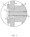
ここで図1を参照すると、蒸発源の中にある有機材料の気化を制御して基板の表面に堆積させるための本発明による装置の断面図が示してある。装置10は蒸発源であり、初期量の有機材料20と、その有機材料20を制御された速度で第1の温度制御領域30から第2の温度制御領域50に移動させる計量・供給装置60とを備えている。計量・供給装置60は、例えばスクリュー、または同様のスクリュー構造にすることができる。このような計量・供給装置と、ある体積の有機材料をその計量・供給装置に供給する方法は、譲受人に譲渡されたアメリカ合衆国特許出願第10/945,940号の中にLongらが記載している(その内容は参考としてこの明細書に組み込まれているものとする)。第1の温度制御領域30は、熱質量の大きな領域(例えば大きな基部)にすることができ、有機材料20をその材料の気化温度よりも低い望む温度に維持するために金属やセラミックなどの材料を含むことができる。第1の温度制御領域30は、必要に応じて加熱または冷却することができ、第1の加熱装置を備えている。この加熱装置は、よく知られている任意の加熱装置(例えば加熱コイル、誘導加熱、加熱/冷却管など)にすることができる。図を見やすくするため、第1の加熱装置は図示していない。第1の温度制御領域30は加熱され、有機材料20の気化温度よりも低い温度に維持される。
Referring now to FIG. 1, there is shown a cross-sectional view of an apparatus according to the present invention for controlling vaporization of an organic material in an evaporation source and depositing it on the surface of a substrate. The
気化温度は、有機材料20の蒸気圧が、基板上に有機材料の層を効率的に形成するのに十分な大きさになる最低温度として定義される。“効率的に”とは、実際的な製造速度を意味する。材料の蒸気圧は温度の連続関数であるため、ゼロではないどの絶対温度でも材料の蒸気圧はゼロではない。気化温度に関する上記の定義は、実際的な蒸着装置の内部におけるさまざまな領域の動作条件と相対温度を記述するのに役立つ。 The vaporization temperature is defined as the lowest temperature at which the vapor pressure of the organic material 20 is large enough to efficiently form a layer of organic material on the substrate. “Efficiently” means a practical production rate. Since the vapor pressure of a material is a continuous function of temperature, the vapor pressure of a material is not zero at any non-zero absolute temperature. The above definition for vaporization temperature serves to describe the operating conditions and relative temperatures of various regions within a practical vapor deposition apparatus.
関連する1つの問題は、凝縮温度である。材料の部分圧が所定の値のとき、適切なある温度以下に維持した表面に材料の蒸気が凝縮するであろう。この温度は凝縮温度として定義され、材料の蒸気の部分圧に依存する。 One related problem is the condensation temperature. When the partial pressure of the material is a predetermined value, the vapor of the material will condense on a surface maintained below an appropriate temperature. This temperature is defined as the condensation temperature and depends on the partial pressure of the material vapor.
装置10は、マニホールドにもなる。この装置の一部をマニホールドの壁部80として示してある。マニホールドは1つ以上の開口部を備えており、その中を気化した有機材料が通過して基板の表面に堆積される。Longらは、譲受人に譲渡された上記のアメリカ合衆国特許出願第10/945,940号の中で、適切なマニホールドの実例について検討している(その内容は参考としてこの明細書に組み込まれているものとする)。マニホールドは、点蒸発源と一般に呼ばれるタイプのものと似た、開口部が1つで壁面が加熱される構造体で構成することもできる。
The
第2の温度制御領域50は、第1の温度制御領域30の端部から第2の加熱装置40までの領域である。第2の加熱装置40は、有機材料20から見て熱質量が非常に小さな加熱素子にすることができる。このような加熱素子としては透過性加熱素子(例えばワイヤ・メッシュ・スクリーン、網状多孔性構造(細かい間膜))などがあり、誘導やRFエネルギーによって加熱すること、またはその長さ方向に電流を流すことによって加熱することができる。第2の加熱装置40は、第2の温度制御領域50において有機材料20をその材料の気化温度よりも高温に加熱する。その結果、加熱された有機材料の蒸気圧が十分に大きくなって基板上に層が有効に形成されるとともに、透過性加熱素子に隣接する有機材料が気化してマニホールドの中に放出される。有機材料20は、あらかじめ決められた制御された速度で計量されて第2の温度制御領域50に供給される。すると有機材料20は熱によって制御された速度で気化し、その気化した有機材料は透過性加熱素子(すなわち第2の加熱装置40)を通過してマニホールドの中に入り、そしてマニホールドの開口部から出ていく。この実施態様では、第2の加熱装置40がマニホールドの内部にある状態を図示してあるが、第2の加熱装置40がマニホールドと連続している実施態様では、第2の加熱装置40とマニホールドの接続部の体積がマニホールドの内部体積と比べて小さい限り、第2の加熱装置40をマニホールドの外に置くことができる。加熱装置がマニホールドから離れている実施態様では、接続部が気化した有機材料の凝縮温度よりも高温に維持されている限り、接続部の体積は重要でない。
The second
実際には、有機材料20の気化は、有機材料20の計量・供給を制御することによって、または第2の温度制御領域50で加熱する有機材料20の温度を制御することによって、またはその両方によって制御することができる。第2の温度制御領域50における温度を制御するための制御装置を用い、電位を下げてある電流を第2の加熱装置40に印加することで第2の加熱装置40に加わるRFエネルギーを低下させるとともに、第2の加熱装置40と有機材料20を分離する。第2の加熱装置40と有機材料20を分離することを目的として、第2の加熱装置40を有機材料20から遠ざけるとともに、有機材料20を第2の加熱装置40に供給する計量・供給装置を逆行させる機械式構造が設けられている。第1の状態では、有機材料20の温度が、基板上に層を有効に形成するのに必要な温度、すなわち気化温度よりも低い温度に維持される。第2の状態では、有機材料20の初期体積のうちで第2の加熱装置40に隣接するわずかな割合(すなわち第1の温度制御領域30と第2の加熱装置40に挟まれた部分)が気化温度よりも高温に加熱される。その結果、加熱された有機材料の蒸気圧は、マニホールドの開口部近くに配置された基板上に層を効果的に形成するのに十分な大きさになる。図1は、第2の加熱装置40が上記のようにして加熱されている第2の状態である。したがってすべての有機材料が単一の蒸発源に収容されているとき、有機材料の初期体積のほんのわずかな割合(10%未満)だけが任意のときに気化温度に加熱される。こうすることで、材料の分解が少なくなる。
In practice, the vaporization of the organic material 20 is controlled by controlling the metering and supply of the organic material 20, or by controlling the temperature of the organic material 20 heated in the second
有機材料20の気化を素早く減らすため、装置10を第1の状態にする。これは、第2の加熱装置40から熱を減らすことによって(例えばその加熱装置に印加する電位を下げ、加熱装置の中を流れる電流を少なくすることによって)、または第2の加熱装置40を有機材料20から離すことによって、または両方の操作を行なうことによって実現できる。図2に、装置10が第1の状態にあるために上記の装置10において加熱装置40が有機材料20から遠ざけられていて、有機材料が気化していないときの断面図が示してある。あるいは加熱装置40を固定し、例えば計量・供給装置60を逆行させることによって有機材料20を加熱装置から遠ざけることもできる。このようにすると、気化速度を最大速度の90%超から10%未満へと5分以内に変化させることができる。3秒未満という時間も実現可能である。有機材料20を例えば第1の温度制御領域30を冷却することによって冷やすこともできる。有機材料20の気化速度を素早く低下させるのにこれらの方法の任意の組み合わせを利用することができる。
In order to quickly reduce the vaporization of the organic material 20, the
気化速度の素早い低下は、気化プロセスの熱時定数を1秒のオーダーにする本発明のいくつかの特徴によって実現される。加熱装置40は薄いため、有機材料20と接触する熱質量は小さい。計量・供給装置60は薄い円筒形状の有機材料20を供給するため、有機材料20は第2の温度制御領域50における断面積は小さいが、ヒート・シンクとして機能できる第1の温度制御領域30と接触する面積ははるかに大きい。
A rapid decrease in vaporization rate is achieved by several features of the present invention that make the thermal time constant of the vaporization process on the order of 1 second. Since the
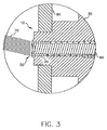
ここで図3を参照すると、蒸発源の中にある有機材料の気化を制御して基板の表面に堆積させるための本発明による別の装置の断面図が示してある。ここには、有機材料20に熱を加える別の方法が示してある。装置10が第2の状態のとき、集束した照射線70が有機材料20の露出面に当てられ、有機材料20の初期体積のわずかな割合が加熱されて気化する。したがってすべての有機材料が単一の蒸発源に収容されているとき、有機材料の初期体積のほんのわずかな割合(10%未満)だけが任意のときに気化温度に加熱される。こうすることで、材料の分解が少なくなる。照射線70は、マイクロ波装置や赤外線装置などを用いて当てることができる。第1の状態では、照射線70はオフにされる。照射線70は、1秒以内にオフとオンを切り換えることができる。そのため有機材料20の気化の停止と開始が数秒でなされる。したがって、蒸発源に収容された有機材料20の気化をこの方法によって素早く制御することで、気化した有機材料の基板の表面への付着を素早く制御することができる。
Referring now to FIG. 3, there is shown a cross-sectional view of another apparatus according to the present invention for controlling the vaporization of organic material in an evaporation source and depositing it on the surface of a substrate. Here, another method of applying heat to the organic material 20 is shown. When the
ここで図4を参照すると、蒸発源から気化する有機材料を制御して基板に堆積させるための本発明による装置の断面図が示してある。装置100は、気化したある量の有機材料を収容するためのマニホールド110が含まれた蒸発源である。マニホールド110は1つ以上の開口部150を備えており、気化した有機材料がその開口部を通って基板160の表面に堆積される。基板160は方向170に沿って移動させることができるため、基板の表面全体が順番にコーティングされる。装置100は、有機材料120と、その有機材料120の全体または一部を気化温度よりも高温に加熱するための加熱装置130(例えば照射線式ヒーター)も備えている。装置100は有機材料120が装填された状態が示してあるが、本発明の他の実施態様に示してあるように、有機材料を計量してマニホールド110に供給し、その計量された材料を例えばスクリュー構造や透過性加熱素子によって加熱する構成にすることもできる。したがってすべての有機材料が単一の蒸発源に収容されているとき、有機材料の全体、または有機材料の初期体積のほんのわずかな割合(10%未満)だけが任意のときに気化温度に加熱される。有機材料の初期体積のほんのわずかな割合(10%未満)だけが任意のときに気化温度に加熱される実施態様では、材料の分解が少なくなる。
Referring now to FIG. 4, there is shown a cross-sectional view of an apparatus according to the present invention for controlling and depositing organic material that evaporates from an evaporation source onto a substrate. The
装置100には、マニホールド110内で気化した有機材料が流れる経路に中空部材140も設けてある。中空部材140は、加熱装置130とは独立に作動する構造体であり、第1の状態においては有機材料が開口部150を通過するのを制限するのに有効であり、第2の状態においては有機材料が開口部150を容易に通過できるようにするのに有効である。中空部材140の外面は温度制御面である。温度制御面とは、中空部材140の外面の温度、したがってその直近の周辺部の温度を温度制御材料(例えばクロロフルオロカーボンなどの冷却流体)で制御して、中空部材140から熱を吸収したり、中空部材140に熱を与えたりできることを意味する。温度制御材料は、例えばそのような温度制御材料を供給するための構造体(例えばポンプやコンプレッサ)により、中空部材140の内側を通って制御された温度で供給することができる。第1の状態では、中空部材140は冷却されるため、気化した有機材料が中空部材140の表面に堆積され、基板160の表面には堆積されない。この状態では有機材料が開口部150から出ていくことはないため、基板160の表面に堆積されない。第2の状態では、中空部材140はマニホールド110の内部体積とほぼ同じ温度に維持されるため、開口部150に向かう気化した有機材料の流れに与える影響、したがって基板160の表面に与える影響を最少にする上で中空部材140は有効である。さらなる制御を行なうことが、中空部材140が第1の状態で有効であるときには加熱装置130からの熱を減らすことによって、中空部材140が第2の状態で有効であるときには加熱装置130からの熱を増やすことによって実現できる。
The
ここで図5を参照すると、蒸発源から気化する有機材料を制御して基板に堆積させるための本発明による別の装置の概略図が示してある。ある量の有機材料が装置200に供給され、この装置200が蒸発源になる。有機材料は、計量・供給装置230(例えばすでに説明したスクリュー構造)によって供給することができる。他の実施態様では、有機材料を塊として供給し、上に説明したようにそのほんの一部を所定のときに気化温度に加熱できること、または蒸発源から離れた加熱装置から気化した有機材料を供給できることも理解されよう。後者の場合、蒸発源との接続部は、気化した有機材料の凝縮温度よりも高温に維持される。図示した実施態様では、加熱装置240からの熱が、例えばスクリュー構造を利用して有機材料に加えられ、有機材料が透過性加熱素子に移動する。したがってすべての有機材料が単一の蒸発源に収容されているとき、有機材料の初期体積のほんのわずかな割合(10%未満)だけが任意のときに気化温度に加熱される。こうすることで、材料の分解が少なくなる。有機材料は加熱装置240によって気化してマニホールド210に入り、開口部220から出ることで、マニホールド210の外側にあって開口部220の近くに位置する基板160の表面に堆積される。装置200は、マニホールド210の中では有機蒸気のコンダクタンスが大きいのに対し、開口部220を通過する有機蒸気のコンダクタンスはより小さくなるように構成されている。装置200は、気化した有機材料が開口部220を通過するのを制限する第1の状態と、気化した有機材料が開口部220を容易に通過できるようにする第2の状態を加熱装置240とは独立に提供するための制御装置も備えている。装置200では、制御装置は、流路260とバルブ250を備えた構造255である。構造255は、マニホールド210と連続した状態にすること、またはマニホールド210から離すことができる。ただし、構造255と加熱装置240の少なくとも一方はマニホールド210と連続していなくてはならない。構造255は、加熱装置240と独立に作動し、第1の状態では気化した有機材料が開口部220を通過するのを制限するのに有効であり、第2の状態では気化した有機材料が開口部220を容易に通過できるようにするのに有効である。気化した有機材料の流れは、バルブ250を開放することによってマニホールド210から第1の流路260へと迅速に方向転換させることができる。第1の状態では、バルブ250を開放することによって第1の流路260が開くため、気化した有機材料は基板160の表面に堆積されない。第2の状態では、バルブ250が閉じられるため、有機材料を基板160の上に堆積させることができる。基板160の表面への気化した有機材料の堆積は、素早く開始させたり停止させたりすることができる。
Referring now to FIG. 5, there is shown a schematic diagram of another apparatus according to the present invention for controlling and depositing organic material vaporized from an evaporation source on a substrate. A certain amount of organic material is supplied to the
ここで図6を参照すると、蒸発源から気化する有機材料を制御して基板に堆積させるための本発明による別の装置の概略図が示してある。ある量の有機材料が装置270に供給される。この装置270が蒸発源である。装置270は、1つ以上の開口部220を有するマニホールド210と、マニホールドと連続した位置、またはマニホールドから離れた位置から有機材料をその材料の気化温度よりも高温に加熱する装置と、リザーバ310と、リザーバ310をマニホールド210に接続する流路290を区画する構造と、流路290をリザーバ310と接続してマニホールド210内の気化した有機材料の圧力を低下させることのできる別の構造とを備えている。これらについてさらに詳しく説明する。有機材料は、計量・供給装置230(例えばすでに説明したスクリュー構造)から供給することができる。すでに説明したように、有機材料を塊として供給し、その一部だけを所定のときに気化温度に加熱できることも理解されよう。加熱装置240からの熱は、例えばスクリュー構造を利用して有機材料を透過性加熱素子に移動させることによってその有機材料に伝えられる。したがってすべての有機材料は単一の蒸発源に収容され、有機材料の初期体積のわずかな割合(10%未満)だけが任意のときに気化温度に加熱される。こうすることで、材料の分解が少なくなる。有機材料は加熱装置240によって気化してマニホールド210に入り、開口部220から出てゆき、マニホールド210の外側にあって開口部220の近くに配置された基板160の表面に堆積される。
Referring now to FIG. 6, there is shown a schematic diagram of another apparatus according to the present invention for controlling and depositing organic material that evaporates from an evaporation source onto a substrate. An amount of organic material is supplied to the device 270. This device 270 is an evaporation source. The apparatus 270 includes a manifold 210 having one or
装置270は、マニホールド210の中では有機蒸気のコンダクタンスが大きいのに対し、開口部220を通過する有機蒸気のコンダクタンスはより小さくなるように構成されている。流路290、バルブ295、リザーバ310、不活性ガス入口280、バルブ285は、加熱装置240とは独立に動作する構造を表わし、第1の状態では気化した有機材料が開口部220を通過するのを制限するのに有効であり、第2の状態では気化した有機材料が開口部220を容易に通過できるようにするのに有効である。第1の流路290にはマニホールド210が接続されている。リザーバ310は第1の流路290に接続できるようにされており、例えば方向転換した有機材料の凝縮温度よりもリザーバ310の温度を低温にすることにより、マニホールド210からのその気化した有機材料を保管する機能を持つ。装置270は、不活性ガス入口280と、不活性ガス(例えば窒素)をマニホールド210に供給するためのバルブ285も備えている。気化した有機材料の流れは、バルブ295を開くことによってマニホールド210から素早く方向転換して第1の流路290に入ることができる。第1の状態では、バルブ295を開くことによって第1の流路290が開放され、バルブ285を開くことによって不活性ガスが不活性ガス入口280を通じてマニホールド210に供給される。その結果、気化した有機材料がリザーバ310に供給される。このようにすると気化した有機材料をマニホールド210の内部から素早く追い出すことができる。第2の状態では、バルブ285と295が閉じられることによってリザーバ310への第1の流路290が閉鎖されるため、基板160に有機材料を堆積させることが可能になる。基板160の表面への気化した有機材料の堆積は、素早く開始したり停止させたりすることができる。この装置の1つの利点は、外部にある基板への有機材料の流れを止めるのに加熱装置240をオフにする必要がないことである。したがって外部にある基板のコーティングを再開する準備ができたとき、バルブ285と295を閉じてマニホールド210を素早く有機材料の蒸気で満たすだけでよい。
The device 270 is configured such that the conductance of the organic vapor passing through the
ここで図7aと図7bを参照すると、蒸発源から気化する有機材料を制御して基板に堆積させるための本発明による別の装置の断面図が示してある。装置300は、ある量の気化した有機材料を収容するためのマニホールド110を備える蒸発源である。マニホールド110は1つ以上の開口部150を備えており、その中を気化した有機材料が通過して基板160の表面に堆積される。基板160は方向170に沿って移動させることができるため、基板160の全表面が順番にコーティングされる。装置300は、有機材料120と、有機材料120の全体または一部を気化温度よりも高温に加熱するための加熱装置130(例えば照射線式ヒーター)も備えている。装置300は有機材料120が装填された状態が示してあるが、本発明の他の実施態様に示してあるように、有機材料を計量してマニホールド110に供給し、その計量された材料を例えばスクリュー構造と透過性加熱素子によって加熱する構成にすることもできる。したがって全有機材料が単一の蒸発源に収容されているとき、有機材料のすべて、または有機材料の初期体積のわずかな割合だけ(10%未満)が任意のときに気化温度に加熱される。有機材料の初期体積のわずかな割合だけ(10%未満)が任意のときに気化温度に加熱される実施態様では、材料の分解が少なくなる。
Referring now to FIGS. 7a and 7b, there is shown a cross-sectional view of another apparatus according to the present invention for controlling and depositing organic material that evaporates from an evaporation source onto a substrate. The
装置300は、マニホールドと連続した可動部材330も備えている。可動部材330は、加熱装置130とは独立に作動する構造であり、第1の状態では気化した有機材料が開口部150を通過するのを制限するのに有効であり、第2の状態では気化した有機材料が開口部150を容易に通過できるようにするのに有効である。可動部材330は、第1の状態では、図7aに示したように、気化した有機材料の流れが開口部150を通過するのを制限する。この状態では、気化した有機材料が開口部150から出ていくことはないため、基板160の表面に堆積されない。第2の状態では、図7bに示したように、可動部材330により、基板160をコーティングしたいときに気化した有機材料の流れを開口部150を通過させることができる。さらなる制御を行なうことが、可動部材330が第1の状態で有効であるときに加熱装置130からの熱を減らし、可動部材330が第2の状態で有効であるときに加熱装置130からの熱を増やすことによって実現できる。
The
ここで図8を参照すると、蒸発源から気化する有機材料を制御して基板に堆積させるための本発明による別の装置の断面図が示してある。装置350は上記の装置300と同様の蒸発源であるが、マニホールド110の内部に可動部材340を備えている点が異なっている。可動部材340は、マニホールド110の内部にある機構を通じて、または一部がマニホールド110の外にあるバッフル操作装置を通じて移動させることができる。可動部材340は、開口部150を塞ぐ位置に移動させることができるため、有機材料の流れが開口部を通過するのが阻止される。
Referring now to FIG. 8, there is shown a cross-sectional view of another apparatus according to the present invention for controlling and depositing organic material that evaporates from an evaporation source onto a substrate. The
単一の可動部材に加え、マイクロ電子機械システム(MEMS)の中で多数の可動部材を使用することもできる。その場合には、気化した有機材料の流れを制限するために個々の開口部150が可動部材を備えている。このようなMEMSシステムは、ピストン、プランジャ、バイメタル・リボンなどを備えることができる。
In addition to a single movable member, multiple movable members can be used in a microelectromechanical system (MEMS). In that case, each
これら実施態様に示した可動部材は、従来技術で使用されているシャッターとは異なることを理解されたい。基板のコーティングを阻止するのに用いられてきたシャッターは、気化した有機材料の流れが基板に向かうのを阻止するために使用される。しかし有機材料の気化は減少することなく継続するため、材料の蒸気が蒸発源の領域から離れ(すなわち発散され)続け、シャッターの表面と、シャッターによって保護されていない他の表面に堆積される。気化した有機材料は開口部を通過して基板の表面に堆積されるが、本発明では可動部材が開口部を塞ぐことで、蒸発源から材料が発散する速度を低下させる一方で、蒸発源内の動作圧力を維持する。以下、本発明の好適な態様を列挙する。
(態様1)気化した有機材料の基板表面への堆積を制御する方法であって、
(a)加熱装置を用意して有機材料を気化させ;
(b)基板表面に堆積させるために気化した有機材料を通過させる少なくとも1つの開口部を有するマニホールドを用意し;
(c)上記加熱装置とは独立に作動し、第1の状態では、上記開口部を気化した有機材料が通過するのを制限するのに有効で、第2の状態では、上記開口部を気化した有機材料が通過するのを容易にするのに有効な制御装置を用意し;
(d)上記加熱装置と上記制御装置の一方または両方を上記マニホールドと連続した状態にする操作を含む方法。
(態様2)上記制御装置が、上記開口部を気化した有機材料が通過するのを制限する第1の状態と、上記開口部を気化した有機材料が通過させることのできる第2の状態との間を移動できる部材を備える、態様1に記載の方法。
(態様3)上記加熱装置からの熱を、上記制御装置が第1の状態で有効であるときに減らし、第2の状態で有効であるときに増やす、態様1に記載の方法。
(態様4)気化した有機材料の流れを上記マニホールドから方向転換させる操作をさらに含んでおり、その操作を、
(e)上記マニホールドに接続された第1の流路を用意し;
(f)気化して方向転換した上記有機材料を保管するために上記第1の流路に接続できるリザーバを用意し;
(g)第1の状態で上記リザーバへの上記第1の流路を開放して気化した有機材料をそのリザーバに供給し、第2の状態で上記リザーバへの上記第1の流路を閉じることによって行なう、態様1に記載の方法。
(態様5)第1の状態にあるときに上記マニホールドに不活性ガスを供給する、態様4に記載の方法。
(態様6)上記リザーバが、方向転換した上記有機材料の凝縮温度よりも低温である、態様4に記載の方法。
(態様7)上記制御装置が中空部材を備えており、
i)温度制御面を有する上記中空部材をマニホールド内の気化した有機材料の流路の中に配置するが、そのとき、その中空部材が、第2の状態では気化した有機材料の流れに与える影響を最少にし、第1の状態ではその中空部材の表面に気化した有機材料を堆積させるが、基板の表面には堆積させないようにし;
ii)温度制御された材料を上記中空部材の中に供給し、その中空部材の温度制御面から熱を吸収するか、その温度制御面に熱を供給する操作をさらに含む、態様1に記載の方法。
(態様8)上記加熱装置から供給される熱を減らす操作をさらに含む、態様7に記載の方法。
(態様9)蒸発源から基板表面への有機材料の堆積を制御するための装置であって、
a)少なくとも1つの開口部を有するマニホールドと;
b)有機材料をその有機材料の気化温度よりも高温に加熱する加熱装置と;
c)上記マニホールドの中に位置する中空部材と;
d)温度制御材料を上記中空部材に供給し、熱をその中空部材から吸収するか、熱をその中空部材に供給する手段とを備える装置。
(態様10)蒸発源から基板表面への有機材料の堆積を制御するための装置であって、
a)少なくとも1つの開口部を有するマニホールドと;
b)有機材料をその有機材料の気化温度よりも高温に加熱する加熱装置と;
c)リザーバと;
d)上記リザーバを上記マニホールドに接続する流路を区画する手段と;
e)上記流路を上記リザーバに接続して上記マニホールド内の気化した有機材料の圧力を下げる手段とを備える装置。
(態様11)上記リザーバが、方向癲癇させた上記有機材料の凝縮温度よりも低温である、態様10に記載の装置。
(態様12)蒸発源から基板表面への有機材料の堆積を制御するための装置であって、
a)少なくとも1つの開口部を有するマニホールドと;
b)有機材料をその有機材料の気化温度よりも高温に加熱する加熱装置と;
c)上記加熱装置とは独立に、上記開口部を気化した有機材料が通過するのを制限する第1の状態と、上記開口部を気化した有機材料が通過するのを容易にする第2の状態を提供する制御装置とを備える装置。
(態様13)上記加熱装置と上記制御装置が、
i)第1の温度制御領域で上記有機材料をその有機材料の気化温度よりも低い温度まで加熱する第2の加熱装置をさらに備え;
ii)上記第1の加熱装置により、第2の温度制御領域で上記有機材料を気化温度よりも高温に加熱し;
上記加熱装置と上記制御装置が、
iii)上記有機材料を計量して第1の温度制御領域から第2の温度制御領域に供給することにより、その有機材料を気化させて上記マニホールドの中に放出する手段と;
iv)上記第2の加熱装置を上記有機材料と分離する手段とをさらに備える、態様12に記載の装置。
(態様14)上記第2の加熱装置が透過性加熱素子を備える、態様13に記載の装置。
It should be understood that the movable members shown in these embodiments are different from the shutters used in the prior art. Shutters that have been used to block the coating of the substrate are used to block the flow of vaporized organic material toward the substrate. However, since the vaporization of the organic material continues without diminishing, the vapor of the material continues to leave (i.e., escape) the area of the evaporation source and is deposited on the surface of the shutter and other surfaces not protected by the shutter. The vaporized organic material passes through the opening and is deposited on the surface of the substrate.In the present invention, the movable member closes the opening to reduce the rate at which the material diverges from the evaporation source, while in the evaporation source. Maintain operating pressure. Hereinafter, preferred embodiments of the present invention will be listed.
(Aspect 1) A method for controlling deposition of vaporized organic material on a substrate surface,
(A) Prepare a heating device to vaporize the organic material;
(B) providing a manifold having at least one opening through which the vaporized organic material passes for deposition on the substrate surface;
(C) Operates independently of the heating device, and is effective in limiting the passage of vaporized organic material through the opening in the first state, and vaporizing the opening in the second state. Providing an effective control device to facilitate the passage of the organic material;
(D) A method including an operation of making one or both of the heating device and the control device continuous with the manifold.
(Aspect 2) A first state in which the control device restricts the passage of the vaporized organic material through the opening, and a second state in which the vaporized organic material can pass through the opening. A method according to aspect 1, comprising a member that can move between.
(Aspect 3) The method according to aspect 1, wherein the heat from the heating device is reduced when the control device is effective in the first state and increased when the control device is effective in the second state.
(Aspect 4) The method further includes an operation of turning the flow of the vaporized organic material from the manifold, and the operation includes:
(E) providing a first flow path connected to the manifold;
(F) providing a reservoir connectable to the first flow path for storing the vaporized and redirected organic material;
(G) The vaporized organic material is supplied to the reservoir by opening the first channel to the reservoir in the first state, and the first channel to the reservoir is closed in the second state. A method according to embodiment 1, wherein
(Aspect 5) The method according to Aspect 4, wherein an inert gas is supplied to the manifold when in the first state.
(Aspect 6) The method according to Aspect 4, wherein the reservoir has a temperature lower than the condensation temperature of the redirected organic material.
(Aspect 7) The control device includes a hollow member,
i) The hollow member having the temperature control surface is disposed in the flow path of the vaporized organic material in the manifold. At that time, the hollow member affects the flow of the vaporized organic material in the second state. And vaporized organic material is deposited on the surface of the hollow member in the first state, but not on the surface of the substrate;
The method according to aspect 1, further comprising an operation of supplying a temperature-controlled material into the hollow member and absorbing heat from the temperature control surface of the hollow member or supplying heat to the temperature control surface. Method.
(Aspect 8) The method according to Aspect 7, further comprising an operation of reducing heat supplied from the heating device.
(Aspect 9) An apparatus for controlling the deposition of an organic material from an evaporation source onto a substrate surface,
a) a manifold having at least one opening;
b) a heating device for heating the organic material to a temperature higher than the vaporization temperature of the organic material;
c) a hollow member located in the manifold;
d) An apparatus comprising: means for supplying a temperature control material to the hollow member and absorbing heat from the hollow member or supplying heat to the hollow member.
(Aspect 10) An apparatus for controlling the deposition of an organic material from an evaporation source onto a substrate surface,
a) a manifold having at least one opening;
b) a heating device for heating the organic material to a temperature higher than the vaporization temperature of the organic material;
c) with a reservoir;
d) means for defining a flow path connecting the reservoir to the manifold;
e) An apparatus comprising means for connecting the flow path to the reservoir and reducing the pressure of the vaporized organic material in the manifold.
(Aspect 11) The apparatus according to
(Aspect 12) An apparatus for controlling the deposition of an organic material from an evaporation source onto a substrate surface,
a) a manifold having at least one opening;
b) a heating device for heating the organic material to a temperature higher than the vaporization temperature of the organic material;
c) Independently of the heating device, a first state that restricts passage of the vaporized organic material through the opening, and a second state that facilitates passage of the vaporized organic material through the opening. And a control device for providing a state.
(Aspect 13) The heating device and the control device are
i) further comprising a second heating device for heating the organic material to a temperature lower than a vaporization temperature of the organic material in the first temperature control region;
ii) heating the organic material to a temperature higher than the vaporization temperature in the second temperature control region by the first heating device;
The heating device and the control device are
iii) means for metering and supplying the organic material from the first temperature control region to the second temperature control region to vaporize the organic material and release it into the manifold;
iv) The device according to aspect 12, further comprising means for separating the second heating device from the organic material.
(Aspect 14) The apparatus according to aspect 13, wherein the second heating device includes a permeable heating element.
10 装置
20 有機材料
30 第1の温度制御領域
40 加熱装置
50 第2の温度制御領域
60 計量・供給装置
70 照射線
80 マニホールドの壁部
100 装置
110 マニホールド
120 有機材料
130 加熱装置
140 中空部材
150 開口部
160 基板
170 方向
200 装置
210 マニホールド
220 開口部
230 計量・供給装置
240 加熱装置
250 バルブ
255 構造
260 流路
270 装置
280 不活性ガス入口
285 バルブ
290 流路
295 バルブ
300 装置
310 リザーバ
330 可動部材
340 可動部材
350 装置
10 Equipment
20 Organic materials
30 First temperature control area
40 Heating device
50 Second temperature control area
60 Weighing / feeding equipment
70 Irradiation
80 Manifold wall
100 devices
110 Manifold
120 Organic materials
130 Heating device
140 Hollow parts
150 opening
160 substrates
170 direction
200 devices
210 Manifold
220 opening
230 Weighing and supply equipment
240 Heating device
250 valves
255 structure
260 flow path
270 devices
280 Inert gas inlet
285 valve
290 flow path
295 valve
300 devices
310 reservoir
330 Moving parts
340 Movable parts
350 equipment
Claims (2)
(a)加熱装置を用意して有機材料を気化させ;
(b)基板表面に堆積させるために気化した有機材料を通過させる複数の開口部を有するマニホールドを用意し;
(c)上記加熱装置とは独立に作動し、第1の状態では、上記開口部を気化した有機材料が通過するのを制限するのに有効で、第2の状態では、上記開口部を気化した有機材料が通過するのを容易にするのに有効な制御装置を用意し;
(d)上記加熱装置と上記制御装置の一方または両方が上記マニホールドと連続しており、
気化した有機材料の流れを上記マニホールドから方向転換させる操作をさらに含んでおり、その操作を、
(e)上記マニホールドに接続された第1の流路を用意し;
(f)気化して方向転換した上記有機材料を保管するために上記第1の流路に接続できるリザーバを用意し;
(g)第1の状態で不活性ガスを供給すると共に上記リザーバへの上記第1の流路を開放して気化した有機材料をそのリザーバに供給し、第2の状態で上記リザーバへの上記第1の流路を閉じることによって行なうことを特徴とする、方法。 A method for controlling the deposition of vaporized organic material on a substrate surface, comprising:
(A) Prepare a heating device to vaporize the organic material;
(B) providing a manifold having a plurality of openings through which the vaporized organic material passes for deposition on the substrate surface;
(C) Operates independently from the heating device, and is effective in limiting the passage of the vaporized organic material through the opening in the first state, and vaporizing the opening in the second state. Providing an effective control device to facilitate the passage of the organic material;
(D) one or both of the heating device and the control device are continuous with the manifold ;
And further including an operation of diverting the flow of the vaporized organic material from the manifold.
(E) providing a first flow path connected to the manifold;
(F) providing a reservoir connectable to the first flow path for storing the vaporized and redirected organic material;
(G) Supplying an inert gas in the first state and opening the first flow path to the reservoir to supply the vaporized organic material to the reservoir; and supplying the inert material to the reservoir in the second state A method characterized in that it is performed by closing the first flow path .
Applications Claiming Priority (3)
| Application Number | Priority Date | Filing Date | Title |
|---|---|---|---|
| US10/984,667 | 2004-11-09 | ||
| US10/984,667 US7465475B2 (en) | 2004-11-09 | 2004-11-09 | Method for controlling the deposition of vaporized organic material |
| PCT/US2005/038767 WO2006052467A2 (en) | 2004-11-09 | 2005-10-26 | Controlling the application of vaporized organic material |
Publications (3)
| Publication Number | Publication Date |
|---|---|
| JP2008519905A JP2008519905A (en) | 2008-06-12 |
| JP2008519905A5 JP2008519905A5 (en) | 2008-10-30 |
| JP5270165B2 true JP5270165B2 (en) | 2013-08-21 |
Family
ID=35589528
Family Applications (1)
| Application Number | Title | Priority Date | Filing Date |
|---|---|---|---|
| JP2007540349A Active JP5270165B2 (en) | 2004-11-09 | 2005-10-26 | Control of adhesion of vaporized organic materials |
Country Status (8)
| Country | Link |
|---|---|
| US (1) | US7465475B2 (en) |
| EP (5) | EP1831421B1 (en) |
| JP (1) | JP5270165B2 (en) |
| KR (1) | KR101212581B1 (en) |
| CN (1) | CN101052738B (en) |
| DE (1) | DE602005022765D1 (en) |
| TW (1) | TWI382098B (en) |
| WO (1) | WO2006052467A2 (en) |
Families Citing this family (7)
| Publication number | Priority date | Publication date | Assignee | Title |
|---|---|---|---|---|
| US7465475B2 (en) | 2004-11-09 | 2008-12-16 | Eastman Kodak Company | Method for controlling the deposition of vaporized organic material |
| US8986780B2 (en) * | 2004-11-19 | 2015-03-24 | Massachusetts Institute Of Technology | Method and apparatus for depositing LED organic film |
| US7989021B2 (en) | 2005-07-27 | 2011-08-02 | Global Oled Technology Llc | Vaporizing material at a uniform rate |
| JP4959961B2 (en) * | 2005-07-29 | 2012-06-27 | 株式会社ジャパンディスプレイセントラル | Manufacturing method of organic EL element |
| US7883583B2 (en) * | 2008-01-08 | 2011-02-08 | Global Oled Technology Llc | Vaporization apparatus with precise powder metering |
| US8852347B2 (en) * | 2010-06-11 | 2014-10-07 | Tokyo Electron Limited | Apparatus for chemical vapor deposition control |
| US9345573B2 (en) | 2012-05-30 | 2016-05-24 | Neovasc Tiara Inc. | Methods and apparatus for loading a prosthesis onto a delivery system |
Family Cites Families (33)
| Publication number | Priority date | Publication date | Assignee | Title |
|---|---|---|---|---|
| US2447789A (en) * | 1945-03-23 | 1948-08-24 | Polaroid Corp | Evaporating crucible for coating apparatus |
| US3928659A (en) * | 1970-02-12 | 1975-12-23 | Alexander Samuel Baxter | Methods of and means for vacuum deposition |
| JPS58167602A (en) * | 1982-03-29 | 1983-10-03 | Futaba Corp | Formation of thin film of organic substance |
| US5860279A (en) * | 1994-02-14 | 1999-01-19 | Bronicki; Lucien Y. | Method and apparatus for cooling hot fluids |
| US5900279A (en) * | 1995-11-20 | 1999-05-04 | Tri Chemical Laboratory Inc. | Processes for the chemical vapor deposition and solvent used for the processes |
| CN1104259C (en) * | 1996-02-09 | 2003-04-02 | 斯坦内尔公司 | Arrangement for evaporating liquid active material |
| JPH09219289A (en) | 1996-02-09 | 1997-08-19 | Chisso Corp | Organic thin film electroluminescent element and its manufacture |
| US6070551A (en) * | 1996-05-13 | 2000-06-06 | Applied Materials, Inc. | Deposition chamber and method for depositing low dielectric constant films |
| JPH1027761A (en) * | 1996-07-09 | 1998-01-27 | Sony Corp | Chemical reaction device |
| US5804259A (en) * | 1996-11-07 | 1998-09-08 | Applied Materials, Inc. | Method and apparatus for depositing a multilayered low dielectric constant film |
| US5904961A (en) * | 1997-01-24 | 1999-05-18 | Eastman Kodak Company | Method of depositing organic layers in organic light emitting devices |
| KR100353774B1 (en) * | 1997-05-08 | 2002-09-27 | 마츠시타 덴끼 산교 가부시키가이샤 | Device and method for manufacturing an optical recording medium |
| EP0895206A1 (en) | 1997-07-29 | 1999-02-03 | Esselte Meto International GmbH | Security tag for electronic protection of articles |
| US5869135A (en) * | 1997-10-03 | 1999-02-09 | Massachusetts Institute Of Technology | Selective chemical vapor deposition of polymers |
| US6051321A (en) * | 1997-10-24 | 2000-04-18 | Quester Technology, Inc. | Low dielectric constant materials and method |
| US6337102B1 (en) * | 1997-11-17 | 2002-01-08 | The Trustees Of Princeton University | Low pressure vapor phase deposition of organic thin films |
| JP2000068055A (en) | 1998-08-26 | 2000-03-03 | Tdk Corp | Evaporation source for organic el element, manufacturing device for organic el element using the same and manufacture thereof |
| US6237529B1 (en) * | 2000-03-03 | 2001-05-29 | Eastman Kodak Company | Source for thermal physical vapor deposition of organic electroluminescent layers |
| JP2002030419A (en) * | 2000-07-18 | 2002-01-31 | Canon Inc | System and method for film deposition |
| JP2002146516A (en) * | 2000-11-07 | 2002-05-22 | Sony Corp | Vapor deposition method for organic thin film |
| US20030129299A1 (en) * | 2000-11-16 | 2003-07-10 | Swanson Leland S. | Selective deposition of emissive layer in electroluminescent displays |
| JP4593008B2 (en) * | 2001-05-23 | 2010-12-08 | キヤノンアネルバ株式会社 | Vapor deposition source and thin film forming method and apparatus using the same |
| US6749906B2 (en) * | 2002-04-25 | 2004-06-15 | Eastman Kodak Company | Thermal physical vapor deposition apparatus with detachable vapor source(s) and method |
| US7056560B2 (en) * | 2002-05-08 | 2006-06-06 | Applies Materials Inc. | Ultra low dielectric materials based on hybrid system of linear silicon precursor and organic porogen by plasma-enhanced chemical vapor deposition (PECVD) |
| JP3822135B2 (en) * | 2002-05-13 | 2006-09-13 | 日本パイオニクス株式会社 | Vaporization supply device |
| JP2004010990A (en) * | 2002-06-10 | 2004-01-15 | Sony Corp | Thin-film forming apparatus |
| KR100490537B1 (en) * | 2002-07-23 | 2005-05-17 | 삼성에스디아이 주식회사 | Heating crucible and deposit apparatus utilizing the same |
| US6844891B1 (en) * | 2003-07-08 | 2005-01-18 | Eastman Kodak Company | Aligning in five degrees of freedom a multichannel laser printhead for transferring OLED material |
| US6837939B1 (en) * | 2003-07-22 | 2005-01-04 | Eastman Kodak Company | Thermal physical vapor deposition source using pellets of organic material for making OLED displays |
| US7232588B2 (en) * | 2004-02-23 | 2007-06-19 | Eastman Kodak Company | Device and method for vaporizing temperature sensitive materials |
| JP4366226B2 (en) * | 2004-03-30 | 2009-11-18 | 東北パイオニア株式会社 | Organic EL panel manufacturing method, organic EL panel film forming apparatus |
| DE102004041854B4 (en) * | 2004-04-27 | 2008-11-13 | Von Ardenne Anlagentechnik Gmbh | Process and device for thermal vacuum coating |
| US7465475B2 (en) | 2004-11-09 | 2008-12-16 | Eastman Kodak Company | Method for controlling the deposition of vaporized organic material |
-
2004
- 2004-11-09 US US10/984,667 patent/US7465475B2/en active Active
-
2005
- 2005-10-26 EP EP05813907A patent/EP1831421B1/en active Active
- 2005-10-26 EP EP10009971.2A patent/EP2278044B1/en active Active
- 2005-10-26 CN CN2005800379233A patent/CN101052738B/en active Active
- 2005-10-26 EP EP10009954.8A patent/EP2278042B1/en active Active
- 2005-10-26 EP EP10004193A patent/EP2216425A3/en not_active Withdrawn
- 2005-10-26 WO PCT/US2005/038767 patent/WO2006052467A2/en active Application Filing
- 2005-10-26 EP EP10009953.0A patent/EP2278043B1/en active Active
- 2005-10-26 KR KR1020077010467A patent/KR101212581B1/en active IP Right Grant
- 2005-10-26 JP JP2007540349A patent/JP5270165B2/en active Active
- 2005-10-26 DE DE602005022765T patent/DE602005022765D1/en active Active
- 2005-11-08 TW TW094139064A patent/TWI382098B/en active
Also Published As
| Publication number | Publication date |
|---|---|
| WO2006052467A2 (en) | 2006-05-18 |
| EP2278042A1 (en) | 2011-01-26 |
| CN101052738B (en) | 2011-04-27 |
| CN101052738A (en) | 2007-10-10 |
| TWI382098B (en) | 2013-01-11 |
| WO2006052467A3 (en) | 2006-12-21 |
| KR101212581B1 (en) | 2012-12-14 |
| EP2278044B1 (en) | 2017-02-08 |
| US20060099345A1 (en) | 2006-05-11 |
| US7465475B2 (en) | 2008-12-16 |
| EP2278043A1 (en) | 2011-01-26 |
| EP1831421A2 (en) | 2007-09-12 |
| KR20070084078A (en) | 2007-08-24 |
| EP2278042B1 (en) | 2017-02-08 |
| EP2278043B1 (en) | 2016-08-17 |
| TW200622014A (en) | 2006-07-01 |
| EP1831421B1 (en) | 2010-08-04 |
| JP2008519905A (en) | 2008-06-12 |
| DE602005022765D1 (en) | 2010-09-16 |
| EP2278044A1 (en) | 2011-01-26 |
| EP2216425A3 (en) | 2010-11-10 |
| EP2216425A2 (en) | 2010-08-11 |
Similar Documents
| Publication | Publication Date | Title |
|---|---|---|
| JP5270165B2 (en) | Control of adhesion of vaporized organic materials | |
| JP6639580B2 (en) | Evaporator, deposition arrangement, deposition device and method of operating these | |
| JP5551336B2 (en) | Controllable supply of organic materials in the manufacture of OLEDs | |
| JP5144268B2 (en) | Method and apparatus for controlling vaporization of organic materials | |
| TWI467040B (en) | Evaporator for organic materials | |
| US20050287299A1 (en) | Method and apparatus using large-area organic vapor deposition for formation of organic thin films or organic devices | |
| JP2009097044A (en) | Film deposition apparatus and film deposition method | |
| KR20170026532A (en) | Device and method for generating vapor for a cvd- or pvd device | |
| TW200927964A (en) | Device for generating vapor of organic materials, film forming source and film forming device | |
| KR20160095091A (en) | Depositing arrangement, deposition apparatus and methods of operation thereof | |
| EP1893785A2 (en) | Method for feeding powdered or granular material | |
| KR101323249B1 (en) | The method and apparatus to fabricate superconducting coated conductor | |
| JP2008519905A5 (en) | ||
| JP5647854B2 (en) | Film forming apparatus and film forming method | |
| KR20070006460A (en) | Gas feeding line |
Legal Events
| Date | Code | Title | Description |
|---|---|---|---|
| A521 | Request for written amendment filed |
Free format text: JAPANESE INTERMEDIATE CODE: A523 Effective date: 20080910 |
|
| A621 | Written request for application examination |
Free format text: JAPANESE INTERMEDIATE CODE: A621 Effective date: 20080910 |
|
| A711 | Notification of change in applicant |
Free format text: JAPANESE INTERMEDIATE CODE: A711 Effective date: 20100804 |
|
| A131 | Notification of reasons for refusal |
Free format text: JAPANESE INTERMEDIATE CODE: A131 Effective date: 20110719 |
|
| A601 | Written request for extension of time |
Free format text: JAPANESE INTERMEDIATE CODE: A601 Effective date: 20111017 |
|
| A602 | Written permission of extension of time |
Free format text: JAPANESE INTERMEDIATE CODE: A602 Effective date: 20111024 |
|
| A521 | Request for written amendment filed |
Free format text: JAPANESE INTERMEDIATE CODE: A523 Effective date: 20120118 |
|
| A02 | Decision of refusal |
Free format text: JAPANESE INTERMEDIATE CODE: A02 Effective date: 20121023 |
|
| A521 | Request for written amendment filed |
Free format text: JAPANESE INTERMEDIATE CODE: A523 Effective date: 20130221 |
|
| A911 | Transfer to examiner for re-examination before appeal (zenchi) |
Free format text: JAPANESE INTERMEDIATE CODE: A911 Effective date: 20130307 |
|
| TRDD | Decision of grant or rejection written | ||
| A01 | Written decision to grant a patent or to grant a registration (utility model) |
Free format text: JAPANESE INTERMEDIATE CODE: A01 Effective date: 20130409 |
|
| A61 | First payment of annual fees (during grant procedure) |
Free format text: JAPANESE INTERMEDIATE CODE: A61 Effective date: 20130509 |
|
| R150 | Certificate of patent or registration of utility model |
Free format text: JAPANESE INTERMEDIATE CODE: R150 Ref document number: 5270165 Country of ref document: JP Free format text: JAPANESE INTERMEDIATE CODE: R150 |
|
| R250 | Receipt of annual fees |
Free format text: JAPANESE INTERMEDIATE CODE: R250 |
|
| R250 | Receipt of annual fees |
Free format text: JAPANESE INTERMEDIATE CODE: R250 |
|
| R250 | Receipt of annual fees |
Free format text: JAPANESE INTERMEDIATE CODE: R250 |
|
| R250 | Receipt of annual fees |
Free format text: JAPANESE INTERMEDIATE CODE: R250 |
|
| R250 | Receipt of annual fees |
Free format text: JAPANESE INTERMEDIATE CODE: R250 |
|
| R250 | Receipt of annual fees |
Free format text: JAPANESE INTERMEDIATE CODE: R250 |
|
| R250 | Receipt of annual fees |
Free format text: JAPANESE INTERMEDIATE CODE: R250 |
|
| R250 | Receipt of annual fees |
Free format text: JAPANESE INTERMEDIATE CODE: R250 |