KR101212581B1 - Controlling the application of vaporized organic material - Google Patents
Controlling the application of vaporized organic material Download PDFInfo
- Publication number
- KR101212581B1 KR101212581B1 KR1020077010467A KR20077010467A KR101212581B1 KR 101212581 B1 KR101212581 B1 KR 101212581B1 KR 1020077010467 A KR1020077010467 A KR 1020077010467A KR 20077010467 A KR20077010467 A KR 20077010467A KR 101212581 B1 KR101212581 B1 KR 101212581B1
- Authority
- KR
- South Korea
- Prior art keywords
- organic material
- manifold
- heating device
- temperature
- deposition
- Prior art date
Links
- 0 CC(C12)C1(C)C(C)(C*)CC(*CC*)[C@@]2C1=CCCCCCCCC1 Chemical compound CC(C12)C1(C)C(C)(C*)CC(*CC*)[C@@]2C1=CCCCCCCCC1 0.000 description 1
- OQYFQAQXGJZBGV-UHFFFAOYSA-N NCCC1C2=CCCC3C2C13 Chemical compound NCCC1C2=CCCC3C2C13 OQYFQAQXGJZBGV-UHFFFAOYSA-N 0.000 description 1
Images


Classifications
-
- C—CHEMISTRY; METALLURGY
- C23—COATING METALLIC MATERIAL; COATING MATERIAL WITH METALLIC MATERIAL; CHEMICAL SURFACE TREATMENT; DIFFUSION TREATMENT OF METALLIC MATERIAL; COATING BY VACUUM EVAPORATION, BY SPUTTERING, BY ION IMPLANTATION OR BY CHEMICAL VAPOUR DEPOSITION, IN GENERAL; INHIBITING CORROSION OF METALLIC MATERIAL OR INCRUSTATION IN GENERAL
- C23C—COATING METALLIC MATERIAL; COATING MATERIAL WITH METALLIC MATERIAL; SURFACE TREATMENT OF METALLIC MATERIAL BY DIFFUSION INTO THE SURFACE, BY CHEMICAL CONVERSION OR SUBSTITUTION; COATING BY VACUUM EVAPORATION, BY SPUTTERING, BY ION IMPLANTATION OR BY CHEMICAL VAPOUR DEPOSITION, IN GENERAL
- C23C14/00—Coating by vacuum evaporation, by sputtering or by ion implantation of the coating forming material
- C23C14/22—Coating by vacuum evaporation, by sputtering or by ion implantation of the coating forming material characterised by the process of coating
- C23C14/54—Controlling or regulating the coating process
- C23C14/542—Controlling the film thickness or evaporation rate
-
- C—CHEMISTRY; METALLURGY
- C23—COATING METALLIC MATERIAL; COATING MATERIAL WITH METALLIC MATERIAL; CHEMICAL SURFACE TREATMENT; DIFFUSION TREATMENT OF METALLIC MATERIAL; COATING BY VACUUM EVAPORATION, BY SPUTTERING, BY ION IMPLANTATION OR BY CHEMICAL VAPOUR DEPOSITION, IN GENERAL; INHIBITING CORROSION OF METALLIC MATERIAL OR INCRUSTATION IN GENERAL
- C23C—COATING METALLIC MATERIAL; COATING MATERIAL WITH METALLIC MATERIAL; SURFACE TREATMENT OF METALLIC MATERIAL BY DIFFUSION INTO THE SURFACE, BY CHEMICAL CONVERSION OR SUBSTITUTION; COATING BY VACUUM EVAPORATION, BY SPUTTERING, BY ION IMPLANTATION OR BY CHEMICAL VAPOUR DEPOSITION, IN GENERAL
- C23C14/00—Coating by vacuum evaporation, by sputtering or by ion implantation of the coating forming material
- C23C14/06—Coating by vacuum evaporation, by sputtering or by ion implantation of the coating forming material characterised by the coating material
- C23C14/12—Organic material
-
- C—CHEMISTRY; METALLURGY
- C23—COATING METALLIC MATERIAL; COATING MATERIAL WITH METALLIC MATERIAL; CHEMICAL SURFACE TREATMENT; DIFFUSION TREATMENT OF METALLIC MATERIAL; COATING BY VACUUM EVAPORATION, BY SPUTTERING, BY ION IMPLANTATION OR BY CHEMICAL VAPOUR DEPOSITION, IN GENERAL; INHIBITING CORROSION OF METALLIC MATERIAL OR INCRUSTATION IN GENERAL
- C23C—COATING METALLIC MATERIAL; COATING MATERIAL WITH METALLIC MATERIAL; SURFACE TREATMENT OF METALLIC MATERIAL BY DIFFUSION INTO THE SURFACE, BY CHEMICAL CONVERSION OR SUBSTITUTION; COATING BY VACUUM EVAPORATION, BY SPUTTERING, BY ION IMPLANTATION OR BY CHEMICAL VAPOUR DEPOSITION, IN GENERAL
- C23C14/00—Coating by vacuum evaporation, by sputtering or by ion implantation of the coating forming material
- C23C14/22—Coating by vacuum evaporation, by sputtering or by ion implantation of the coating forming material characterised by the process of coating
- C23C14/24—Vacuum evaporation
-
- C—CHEMISTRY; METALLURGY
- C23—COATING METALLIC MATERIAL; COATING MATERIAL WITH METALLIC MATERIAL; CHEMICAL SURFACE TREATMENT; DIFFUSION TREATMENT OF METALLIC MATERIAL; COATING BY VACUUM EVAPORATION, BY SPUTTERING, BY ION IMPLANTATION OR BY CHEMICAL VAPOUR DEPOSITION, IN GENERAL; INHIBITING CORROSION OF METALLIC MATERIAL OR INCRUSTATION IN GENERAL
- C23C—COATING METALLIC MATERIAL; COATING MATERIAL WITH METALLIC MATERIAL; SURFACE TREATMENT OF METALLIC MATERIAL BY DIFFUSION INTO THE SURFACE, BY CHEMICAL CONVERSION OR SUBSTITUTION; COATING BY VACUUM EVAPORATION, BY SPUTTERING, BY ION IMPLANTATION OR BY CHEMICAL VAPOUR DEPOSITION, IN GENERAL
- C23C14/00—Coating by vacuum evaporation, by sputtering or by ion implantation of the coating forming material
- C23C14/22—Coating by vacuum evaporation, by sputtering or by ion implantation of the coating forming material characterised by the process of coating
- C23C14/54—Controlling or regulating the coating process
-
- H—ELECTRICITY
- H10—SEMICONDUCTOR DEVICES; ELECTRIC SOLID-STATE DEVICES NOT OTHERWISE PROVIDED FOR
- H10K—ORGANIC ELECTRIC SOLID-STATE DEVICES
- H10K50/00—Organic light-emitting devices
-
- H—ELECTRICITY
- H10—SEMICONDUCTOR DEVICES; ELECTRIC SOLID-STATE DEVICES NOT OTHERWISE PROVIDED FOR
- H10K—ORGANIC ELECTRIC SOLID-STATE DEVICES
- H10K71/00—Manufacture or treatment specially adapted for the organic devices covered by this subclass
-
- H—ELECTRICITY
- H10—SEMICONDUCTOR DEVICES; ELECTRIC SOLID-STATE DEVICES NOT OTHERWISE PROVIDED FOR
- H10K—ORGANIC ELECTRIC SOLID-STATE DEVICES
- H10K71/00—Manufacture or treatment specially adapted for the organic devices covered by this subclass
- H10K71/10—Deposition of organic active material
- H10K71/16—Deposition of organic active material using physical vapour deposition [PVD], e.g. vacuum deposition or sputtering
- H10K71/164—Deposition of organic active material using physical vapour deposition [PVD], e.g. vacuum deposition or sputtering using vacuum deposition
Abstract
기판 표면상으로의 기화된 유기 재료의 증착을 제어하는 방법은, 기화된 유기 재료를 생성하기 위한 가열 장치를 제공하는 단계와, 기판 표면상에 증착할 기화된 유기 재료를 통과시키는 적어도 하나의 개구를 갖는 매니폴드를 제공하는 단계와, 가열 장치와는 독립적으로 작동하고 개구를 통한 기화된 유기 재료의 통과를 제한하는 제 1 상태에서 실행되고 개구를 통한 기화된 유기 재료의 통과를 용이하게 하는 제 2 상태에서 실행되는 제어기를 제공하는 단계를 포함하고, 상기 가열 장치 또는 제어기 또는 그 양자가 매니폴드와 인접하게 배치된다.

A method of controlling the deposition of vaporized organic material onto a substrate surface includes providing a heating device for producing vaporized organic material, and at least one opening through which vaporized organic material to be deposited on the substrate surface passes. Providing a manifold having an opening and operating in a first state that limits the passage of vaporized organic material through the opening and facilitates passage of the vaporized organic material through the opening. Providing a controller running in two states, wherein the heating device or controller or both are disposed adjacent to the manifold.
Description
본 발명은 기화를 발생시키고 증기 기둥(vapor plume)을 형성하여 기판의 표면에 박막을 형성하기 위한 온도로 원료를 가열하는 물리적 증착(physical vapor deposition)의 분야에 관한 것이다.The present invention relates to the field of physical vapor deposition, which generates vaporization and forms vapor plumes to heat the raw material to a temperature for forming a thin film on the surface of the substrate.
진공 분위기에서의 물리적 증착은 예컨대, 분자 OLED 장치에서 유기 재료의 박막을 증착하는 통상적으로 사용되는 방법이다. 그러한 방법은, 예컨대 바(Barr)의 미국 특허 제 2,447,789 호 및 타나베(Tanabe) 등의 유럽 특허 제 0982 411 호에 공지되어 있다. 유기 재료는, 장기간동안 소망의 속도 의존 기화 온도에 또는 그 부근에 유지되면 종종 분해된다. 감응성 유기 재료가 고온에 노출되면, 분자 구조가 변화될 수 있고 관련된 재료 특성이 변화될 수 있다.Physical deposition in a vacuum atmosphere is a commonly used method of depositing thin films of organic materials, for example, in molecular OLED devices. Such a method is known, for example, from US Pat. No. 2,447,789 to Barr and European Patent No. 0982 411 to Tanabe et al. Organic materials often decompose if held at or near the desired rate dependent vaporization temperature for a long time. When sensitive organic materials are exposed to high temperatures, the molecular structure can change and the related material properties can change.
OLED 장치에 사용되는 유기 재료는 소스 온도에 대한 증발 속도의 비선형 의존도가 높다. 소스 온도의 작은 변화가 증발 속도의 매우 큰 변화를 발생시킨다. 이에 불구하고, 종래 기술의 장치는 증발 속도를 제어하는 유일한 방법으로서 소스 온도를 이용하고 있다. 양호한 온도 제어를 달성하기 위해서, 종래 기술의 증착 소스는, 양호하게 절연된 고 열전도율 재료로 이루어지고 고체 체적이 유기 전하 체적보다 더 큰 가열 구조체를 이용하는 것이 일반적이다. 고 열전도율은 구조체를 통하여 양호한 온도 균일성을 보장하고, 큰 열 질량(thermal mass)은 온도 변동을 감소시킴으로써 온도를 임계적으로 작은 범위 내에 유지하는 것을 돕는다. 이러한 방법은 정상 상태의 증발 속도 안정성에 대해 소망하는 효과를 갖지만, 초기에는 악영향을 미친다. 이들 장치는, 안전 상태의 온도 분포 및 그에 따른 안정 증발 속도가 달성되기 전에 초기의 장시간(예컨대, 2 내지 12 시간)동안 작동해야 하는 것이 일반적이다. 또한, 일반적으로 이들 장치는 냉각하는데 장시간을 필요로 하므로, 고가이거나 합성하기 어려울 수 있는 상당량의 유기 재료가 낭비될 수 있다. 또한, 재료가 소스로부터 소모됨에 따라 안정 상태가 서서히 이동하고, 일정한 증발 속도를 유지하기 위해서는 (온도 분포를 변경하기 위해서) 입력 전력을 변화시켜야 한다.Organic materials used in OLED devices have a high nonlinear dependence of evaporation rate on source temperature. Small changes in source temperature cause very large changes in evaporation rate. Nevertheless, the prior art apparatus uses source temperature as the only way to control the evaporation rate. In order to achieve good temperature control, it is common for prior art deposition sources to use heating structures made of well insulated high thermal conductivity materials and having a solid volume larger than the organic charge volume. High thermal conductivity ensures good temperature uniformity throughout the structure, and large thermal mass helps to keep the temperature within critically small ranges by reducing temperature fluctuations. This method has the desired effect on steady state evaporation rate stability, but initially has an adverse effect. These devices are generally required to operate for an initial long time (eg 2 to 12 hours) before the temperature distribution in the safe state and thus a stable evaporation rate is achieved. Also, since these devices generally require a long time to cool, a significant amount of organic material can be wasted, which can be expensive or difficult to synthesize. In addition, as the material is consumed from the source, the steady state moves slowly and the input power must be changed (to change the temperature distribution) to maintain a constant evaporation rate.
재료 수용 소스의 시동 및 냉각을 최소화함으로써 고온에서 재료의 시간을 최소화하고 기계 작동 시간을 최대화하는 현재의 방법은, 동일한 재료의 이중 소스를 연속적으로 사용할 것을 필요로 한다. 예컨대, 하나의 소스를 8일동안 연속적으로 사용하는 것보다는, 2개의 소스를 4일동안 각각 사용할 수 있거나 또는 시동 및 냉각 시간을 중복시킴으로써 1일동안 8개의 소스를 일련의 공정에서 각각 사용할 수 있다. 그러나, 특히 이중 소스의 수 또는 이중 소스를 필요로 하는 재료의 수가 많으면, 이중 소스는 설비의 크기 및 비용을 증가시킨다.Current methods of minimizing material time at high temperatures and maximizing machine operating time by minimizing starting and cooling of the material receiving source require the continuous use of dual sources of the same material. For example, rather than using one source continuously for eight days, two sources may be used for four days each, or eight sources may be used for one day each in a series of processes by overlapping startup and cooling times. . However, especially if the number of dual sources or the number of materials requiring dual sources is large, the dual sources increase the size and cost of the installation.
포레스트 등(미국 특허 공보 제 6,337,102 B1 호)은 유기 재료 및 전구체를 증발시키고 그들을 기판이 위치되는 원자로 용기로 반송하는 방법과, 고체 또는 액체로부터 발생되는 증기의 반송이 운반 가스(carrier gas)의 사용에 의해서 달성되는 것을 개시하고 있다. 유기 재료는, 유입하는 운반 가스를 전체의 가능한 유량으로 포화시키기에 충분히 높은 일정 온도로 유지된다. 증착 속도는 운반 가스의 유량을 조정하는 것에 의해서 제어된다. 상기 발명의 일 실시예에서, 포레스트 등은 적당히 큰 원자로 용기 내에 기판을 배치하고, 원자로 용기로 운반되는 증기를 혼합시키고 기판과 반응시키거나 기판에 응축시킨다. 상기 특허의 다른 실시예는, 큰 면적의 기판의 피복과, 몇개의 그러한 증착 공정을 서로 연속적인 형태로 행하는 것을 포함하는 응용에 관한 것이다. 이 실시예에서, 포레스트 등은 증착 재료의 연속 라인을 기판의 이동 방향에 수직으로 형성하기 위해서 가스 매니폴드(상기 특허 명세서에는 "일 열의 라인을 갖는 중공관"으로서 규정됨)에 의해서 공급되는 가스 커튼(gas curtain)의 사용을 개시하고 있다.Forest et al. (US Pat. No. 6,337,102 B1) describes a method for evaporating organic materials and precursors and returning them to a reactor vessel in which a substrate is located, and the return of vapors from solids or liquids to the use of carrier gas. It is disclosed that what is achieved by. The organic material is maintained at a constant temperature high enough to saturate the incoming carrier gas at the full possible flow rate. The deposition rate is controlled by adjusting the flow rate of the carrier gas. In one embodiment of the invention, the forest or the like places the substrate in a moderately large reactor vessel, mixes the vapor carried to the reactor vessel and reacts with or condenses the substrate. Another embodiment of the patent relates to an application comprising coating a large area substrate and performing several such deposition processes in a continuous fashion with each other. In this embodiment, the forest or the like is a gas supplied by a gas manifold (defined as "hollow tube with one row of lines" in the patent specification) to form a continuous line of deposition material perpendicular to the direction of movement of the substrate. The use of a gas curtain is disclosed.
포레스트 등이 개시한 접근법에서의 한가지 주요한 문제점은, 엄격한 온도 제어를 유지하기 위해서 전체의 재료가 고 열 질량 시스템에서 연속적으로 가열되는 것이다. 이와 같이 장기간동안 고온에 노출되면, 바(Barr)와 타나베(Tanabe) 등이 개시한 방법과 동일한 방식으로 일부 재료의 열화 가능성이 증가한다. 포레스트 등이 개시한 접근법에서의 다른 문제점은, 시스템의 높은 열 질량과 운반 가스 유동을 개시하기 전에 전체의 재료가 균일한 온도로 되어야 하는 요건 때문에, 재료를 재장입하는 냉각 및 개시 시간이 길다는 것이다.One major problem with the approach disclosed by Forest et al. Is that the entire material is continuously heated in a high thermal mass system to maintain strict temperature control. Such prolonged exposure to high temperatures increases the likelihood of degradation of some materials in the same manner as described by Barr and Tanabe. Another problem with the approach disclosed by Forest et al. Is that the high thermal mass of the system and the requirement that the entire material be at a uniform temperature prior to initiating the carrier gas flow results in long cooling and initiation times for reloading the material. will be.
정보 디스플레이 2002 국제 심포지움 협회로부터의 논문 SID Digest 02 pp 891-892에서 어플라이드 필름즈 게엠베하(Applied Films GmbH & Co.)의 호프만(Hoffmann) 등이 개시한 것과 같은 시스템도 기술 분야에 공지되어 있다. 이들 시스템은 바 및 타나베 등이 사용한 유형과 유사한 대형 원격 가열원을 매니폴드와 조합하여 재료 증기를 분배시킨다. 이들 시스템은, 가열 시스템의 높은 열 질량에 기인하는 고온에의 장시간 노출과 장시간의 냉각 및 시동 시간 때문에, 바, 와타나베 등과 포레스트 등이 개시한 방법과 동일한 문제점이 발생한다.Information Display 2002 Papers from the International Symposium Association Systems such as those disclosed by Hoffmann et al. Of Applied Films GmbH & Co. in SID Digest 02 pp 891-892 are also known in the art. These systems combine large remote heating sources, similar to the types used by bars and Tanabe, with manifolds to distribute material vapors. These systems suffer from the same problems as the methods disclosed by bars, Watanabe, Forest, etc., due to prolonged exposure to high temperatures and prolonged cooling and startup time due to the high thermal mass of the heating system.
포레스트 등과 호프만 등이 개시한 것과 같은 증기 반송에 대한 접근법은, 증착 구역의 외부, 그리고 보다 적절하게는 증착 챔버 외부의 장치에서 재료가 증기로 변환되는 "원격 기화(remote vaporization)"을 특징으로 할 수 있다. 유기 증기 단독으로 또는 운반 가스와 함께 증착 챔버 내로 운반되고 최종적으로 기판 표면에 운반된다. 이러한 접근법을 이용할 때는, 적당한 가열 방법을 사용하는 것에 의해서 반송 라인에서의 원치 않는 응축을 피하기 위해서 상당한 주의를 해야 한다. 이러한 문제점은 실질적으로 고온에서 소망의 정도로 증발하는 무기 재료의 사용을 고려하는 경우에 보다 중요하게 된다. 또한, 넓은 면적을 피복하기 위한 증발 물질의 반송은 한결같이 가스 매니폴드의 사용을 필요로 한다.An approach to vapor conveyance, such as disclosed by Forest et al., Hoffman et al., May be characterized by "remote vaporization" in which the material is converted to vapor in an apparatus outside the deposition zone, and more appropriately outside the deposition chamber. Can be. The organic vapor is carried alone or with a carrier gas into the deposition chamber and finally to the substrate surface. When using this approach, great care must be taken to avoid unwanted condensation in the conveying line by using a suitable heating method. This problem becomes even more important when considering the use of inorganic materials that evaporate to a desired degree at substantially high temperatures. In addition, the conveyance of the evaporated material to cover a large area constantly requires the use of a gas manifold.
현재의 원격 기화법은 고 열 질량 가열 시스템에 기인하는 고온에 대한 장시간의 재료의 노출과 시동 및 냉각 지연의 문제점이 있지만, 이러한 시스템은 피복 균일성 및 순간 증착 속도의 제어에 대해서 바와 타나베 등이 개시한 방법보다 다소의 이점을 갖는다. 이러한 원격 제어법은, 포레스트 등의 방법에서 운반 가스용의 밸브 또는 호프만 등의 방법에서 유기 증기용의 밸브를 차단함으로써 증착을 매우 신속하게 중단할 수 있지만, 밸브 하류의 유기 증기 및 운반 가스는, 매니폴드 압력이 증착 챔버 압력으로 하강할 때까지 매니폴드에서 계속 유출할 것이다. 마찬가지로, 이 방법은 증착을 상당히 신속하게 개시할 수 있지만, 매니폴드가 안정 상태의 압력에 도달할 때까지 유기 증기 및 운반 가스가 안정 상태의 증착 속도에 도달하지 않을 것이다. 이것은, 매니폴드로부터 멀리 위치하여 매니폴드와 접촉하지 않는 유기 증기의 흐름을 제어하기 위해서 밸브 등의 구조체와 조합된 원격 기화에 기인하는 문제점이다. 이러한 원격 구조체는 매니폴드 개구를 통한 유기 재료의 통과를 신속하게 제어하지 않으며, 결과적으로 증착의 개시 및 중단을 지연시킨다. 원격 밸브를 갖는 원격 기화 시스템은, 이러한 시스템의 고 열 질량에 기인하는 새로운 재료의 탑재를 위한 긴 시동 및 냉각 시간의 상당한 문제점을 해결하지 않을 뿐만아니라, 이러한 시스템에서 고온으로의 장시간의 노출에 기인하는 재료의 열화의 주요한 문제점을 해결하지도 않는다.Current remote vaporization methods suffer from prolonged exposure of materials to high temperatures and start-up and cooling delays due to high thermal mass heating systems. However, these systems have been described by Bara and Tanabe for control of coating uniformity and instantaneous deposition rates. It has some advantages over the disclosed method. This remote control method can stop vapor deposition very quickly by blocking a valve for carrier gas in a method such as Forest or a valve for organic vapor in a method such as Hoffman, but the organic vapor and carrier gas downstream of the valve It will continue to flow out of the manifold until the fold pressure drops to deposition chamber pressure. Likewise, this method can initiate deposition fairly quickly, but organic vapor and carrier gas will not reach steady deposition rates until the manifold reaches steady pressure. This is a problem due to remote vaporization in combination with structures such as valves to control the flow of organic vapor located away from the manifold and not in contact with the manifold. Such remote structures do not quickly control the passage of organic material through the manifold openings, which in turn delays the start and stop of deposition. Remote vaporization systems with remote valves do not solve the significant problems of long start-up and cooling times for the loading of new materials due to the high thermal mass of these systems, as well as due to prolonged exposure to high temperatures in such systems. It does not solve the major problem of material degradation.
후루카와(Furukawa) 등의 일본 미심사 특허 출원 제 9-219289 호는 플래시 증착(flash vapor deposition)법에 의해서 유기 박막 발광 요소를 형성하는 방법을 개시하고 있다. 이 방법은 신속하게 시작하고 중단할 수 있지만, 후루카와 등이 개시한 방법과 같은 연속 공정으로서 실행할 수는 없다. 유기 재료는 가열된 판 위에 떨어진다. 후루카와의 방법은, 분말 반송 시스템의 특성과, 소망의 체적의 분말이 가열된 판 위에 실제로 낙하하는 것을 어느 정도 보증하는지, 그에 따라서 증발 속도, 증착 막의 두께 및 두께의 균일성이 어느 정도 제어되는지에 대해서 개 시하고 있지 않다. 또한, 방금 발생된 증기의 응축 온도 이하의 온도에서 분말 반송 시스템이 방금 발생된 증기의 일부분이 응축하는 콜드 핑거(cold finger)로서 작용하는 것을 어느 정도 방지하는지에 대해서도 불명확하다.Japanese Unexamined Patent Application No. 9-219289 to Furukawa et al. Discloses a method of forming an organic thin film light emitting element by flash vapor deposition. This method can be started and stopped quickly, but cannot be carried out as a continuous process such as the method disclosed by Furukawa et al. The organic material falls on the heated plate. Furukawa's method ensures that the characteristics of the powder conveying system and the degree to which the desired volume of powder actually falls on the heated plate are controlled accordingly to the degree of evaporation rate, thickness of the deposited film and thickness uniformity. It is not disclosed. It is also unclear to what extent the powder conveying system at a temperature below the condensation temperature of the steam just generated prevents a portion of the just generated steam from acting as a condensed cold finger.
발명의 요약Summary of the Invention
따라서, 본 발명의 목적은 시작 및 정지 시간이 짧은 안정 상태에서 물리적 증착을 달성하는 것이다. 본 발명의 다른 목적은 증착을 연속적으로 그리고 임의의 방향으로 실행할 수 있도록 하는 것이다. 어떤 실시예에서 다른 목적은 다수의 이중 소스로의 반환 없이 유기 재료의 열 촉진 열화를 최소화하는 것이다. 본 발명의 또 다른 목적은, 이중 소스로의 반환 없이 재료를 재탑재하기 위하여 시동 및 냉각 시간을 최소화하는 것이다.Accordingly, it is an object of the present invention to achieve physical deposition in a steady state with short start and stop times. Another object of the present invention is to enable deposition to be carried out continuously and in any direction. In some embodiments, another object is to minimize thermally accelerated degradation of organic materials without returning to multiple dual sources. It is another object of the present invention to minimize start up and cool down times to reload the material without returning to the dual source.
이러한 목적들은, 기판 표면상으로의 증발된 유기 재료의 증착을 제어하는 방법에 있어서,These objects are directed to a method of controlling the deposition of evaporated organic material onto a substrate surface,
(a) 증발된 유기 재료를 생성하기 위한 가열 장치를 제공하는 단계와,(a) providing a heating device for producing evaporated organic material,
(b) 기판 표면상으로의 증착을 위해 증발된 유기 재료가 통과하는 적어도 하나의 개구를 갖는 매니폴드를 제공하는 단계와,(b) providing a manifold having at least one opening through which evaporated organic material passes for deposition onto a substrate surface;
(c) 가열 장치와는 독립적으로 작동하여 개구를 통한 증발된 유기 재료의 통과를 제한하기 위한 제 1 상태에서 실행되고 그리고 개구를 통한 증발된 유기 재료의 통과를 촉진시키기 위한 제 2 상태에서 실행되는 제어기를 제공하는 단계를 포함하며, (c) operating independently of the heating device to run in a first state to limit the passage of the evaporated organic material through the opening and in a second state to promote passage of the evaporated organic material through the opening. Providing a controller,
(d) 상기 가열 장치 또는 제어기, 또는 그 양자가 매니폴드에 인접하는,(d) the heating device or controller, or both adjacent to the manifold,
증착 방법에 의해서 달성된다.Achieved by a deposition method.
본 발명의 이점은, 안정 증발 속도를 신속하게 달성하기 위해서 유기 재료 증기의 증착을 대략 수초 내에 시작 및 중단할 수 있다는 것이다. 이러한 특징은 증착 챔버의 오염을 최소화하고 또 기판이 피복되지 않은 경우 유기 재료를 보존한다.An advantage of the present invention is that the deposition of organic material vapor can be started and stopped in approximately a few seconds in order to quickly achieve a stable evaporation rate. This feature minimizes contamination of the deposition chamber and preserves organic material when the substrate is uncoated.
본 발명의 어떤 실시예의 다른 이점은, 유기 재료의 적은 부분만이 제어된 속도로 소망의 속도 의존 기화 온도로 가열되는 점에서, 종래 기술의 장치의 가열 및 용량의 한계를 극복하는 것이다. 따라서, 본 발명의 특징은 다량의 유기 재료 충전으로 또 안정된 가열 온도로 안정된 증발 속도를 유지하는 것이다. 이 장치는, 소스의 장기간의 작동을 가능하게 함과 아울러 심지어 온도에 매우 민감한 유기 재료의 열화의 위험을 실질적으로 감소시킨다. 또한, 이러한 특징은 상이한 증발 속도 및 열화 온도 임계값을 갖는 재료를 동일한 소스에서 동시에 승화시키는 것을 가능하게 한다. 또한, 이러한 특징은 가열된 재료의 낮은 열 질량에 기인하여 재료의 재탑재 시간을 단축시킬 수 있다.Another advantage of certain embodiments of the present invention is that it overcomes the limitations of heating and capacity of prior art devices in that only a small portion of the organic material is heated to the desired rate dependent vaporization temperature at a controlled rate. Thus, it is a feature of the present invention to maintain a stable evaporation rate with a large amount of organic material filling and at a stable heating temperature. This device enables long-term operation of the source while substantially reducing the risk of deterioration of even highly temperature sensitive organic materials. This feature also makes it possible to sublimate materials with different evaporation rates and degradation temperature thresholds simultaneously in the same source. This feature can also shorten the reload time of the material due to the low thermal mass of the heated material.
본 발명의 어떤 실시예의 다른 이점은, 미세한 속도 제어를 가능하게 하고 또 증발 속도의 독립 측정을 추가로 제공하는 것이다.Another advantage of certain embodiments of the present invention is to enable fine rate control and to further provide an independent measurement of the evaporation rate.
어떤 실시예의 다른 이점은, 본 발명의 장치가 종래 기술의 장치에서보다 재료의 열화 없이 실질적으로 높은 증착 속도를 달성하는 것이다. 또한, 원 재료가 소모됨에 따라 히터 온도의 변화가 필요치 않다.Another advantage of some embodiments is that the device of the present invention achieves substantially higher deposition rates without material degradation than in prior art devices. In addition, no change in heater temperature is required as the raw material is consumed.
본 발명의 어떤 실시예의 다른 이점은, 종래 기술의 장치에서는 가능하지 않 은 임의의 방향으로 증기 소스를 제공할 수 있다는 것이다.Another advantage of certain embodiments of the present invention is that the steam source can be provided in any direction that is not possible with prior art devices.
도 1은 본 발명에 따른 기판 표면상으로의 증발 소스내의 유기 재료의 증발을 제어하는 장치의 단면도,1 is a cross-sectional view of an apparatus for controlling evaporation of organic material in an evaporation source onto a substrate surface according to the present invention;
도 2는 본 발명에 따른 유기 재료의 증발을 제어하기 위한 구성에서의 상기 장치의 단면도,2 is a cross-sectional view of the apparatus in a configuration for controlling evaporation of organic materials according to the present invention;
도 3은 본 발명에 따른 기판 표면상으로의 증발 소스내의 유기 재료의 증발을 제어하는 다른 장치의 단면도,3 is a cross-sectional view of another apparatus for controlling evaporation of organic material in an evaporation source onto a substrate surface according to the present invention;
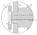
도 4는 본 발명에 따른 증발 소스로부터 기판 표면상으로의 증발된 유기 재료의 증착을 제어하는 장치의 단면도,4 is a cross-sectional view of an apparatus for controlling the deposition of evaporated organic material from an evaporation source onto a substrate surface according to the present invention;
도 5는 본 발명에 따른 증발 소스로부터 기판 표면상으로의 증발된 유기 재료의 증착을 제어하는 다른 장치의 개략도,5 is a schematic representation of another apparatus for controlling the deposition of evaporated organic material from an evaporation source onto a substrate surface in accordance with the present invention;
도 6은 본 발명에 따른 증발 소스로부터 기판 표면상으로의 증발된 유기 재료의 증착을 제어하는 다른 장치의 개략도,6 is a schematic view of another apparatus for controlling the deposition of evaporated organic material from an evaporation source onto a substrate surface according to the present invention;
도 7a는 본 발명에 따른 기화 소스로부터 기판 표면상으로의 증발된 유기 재료의 증착을 제어하는 폐쇄된 구성의 다른 장치의 단면도,7A is a cross-sectional view of another device in a closed configuration for controlling the deposition of evaporated organic material from a vaporization source onto a substrate surface in accordance with the present invention;
도 7b는 개방된 구성의 상기 장치의 단면도,7b is a sectional view of the device in an open configuration,
도 8은 본 발명에 따르는 증발 소스로부터 기판 표면상으로의 증발된 유기 재료의 증착을 제어하는 개방된 구성의 다른 장치의 단면도.8 is a cross-sectional view of another apparatus in an open configuration for controlling the deposition of evaporated organic material from an evaporation source onto a substrate surface in accordance with the present invention.
도면의 주요 부분에 대한 부호의 설명DESCRIPTION OF THE REFERENCE NUMERALS
10 : 장치 20 : 유기 재료10
30 : 제 1 온도 제어 구역 40 : 가열 장치30 first
50 : 제 2 온도 제어 구역 60 : 계량 장치50: second temperature control zone 60: metering device
70 : 복사열 80 : 매니폴드 벽70: radiant heat 80: manifold wall
100 : 장치 110 : 매니폴드100: device 110: manifold
120 : 유기 재료 130 : 가열 장치120: organic material 130: heating device
140 : 중공 부재 150 : 개구140: hollow member 150: opening
160 : 기판 170 : 방향160: substrate 170: direction
200 : 장치 210 : 매니폴드200
220 : 개구 230 : 계량 장치220: opening 230: metering device
240 : 가열 장치 250 : 밸브240: heating device 250: valve
255 : 구조체 260 : 유로255: structure 260: euro
270 : 장치 280 : 불활성 가스 입구270
285 : 밸브 290 : 유로285
295 : 밸브 300 : 장치295
310 : 저장기 330 : 요소310: Saver 330: Element
340 : 요소 350 : 장치340 element 350: device
이제, 도 1을 참조하면, 본 발명에 따르는 기판 표면상으로의 증발 소스 내의 유기 재료의 증발을 제어함으로써 기판 표면상으로의 증발된 유기 재료의 증착을 제어하는 장치의 단면도가 도시되어 있다. 장치(10)는 증발 소스이며, 초기 량의 유기 재료(20)와, 제 1 온도 제어 구역(30)으로부터 제 2 온도 제어 구역(50)으로 제어된 방식으로 유기 재료(20)를 전진시키기 위한 계량 장치(60)를 포함한다. 계량 장치(60)는, 예컨대 나사 스크류(auger screw) 또는 유사한 나사 구조체일 수 있다. 그러한 계량 장치 및 소정량의 유기 재료를 계량 장치에 공급하는 방법은, 위에 인용한 롱(Long) 등의 공동 양도된 미국 특허 출원 제 10/945,940 호에 이미 개시되어 있으며, 상기 특허 문헌의 내용은 본원에 참고로 통합된다. 제 1 온도 제어 구역(30)은 대형 베이스 등의 고 열 질량 영역일 수 있고, 그리고 유기 재료(20)를 기화 온도 이하의 소망의 온도로 유지하기 위해서 금속 및 세라믹 등의 재료를 포함할 수 있다. 제 1 온도 제어 구역(30)은 필요에 따라 가열 및 냉각될 수 있고, 그리고 가열 코일, 유도 가열, 가열/냉각 관 등의 임의의 공지된 가열 장치일 수 있는 제 1 가열 장치를 포함한다. 명확하게 하기 위해 제 1 가열 장치는 도시하지 않았다. 제 1 온도 제어 구역(30)은 가열되어 유기 재료(20)의 기화 온도 이하로 유지된다.Referring now to FIG. 1, there is shown a cross-sectional view of an apparatus for controlling the deposition of evaporated organic materials onto a substrate surface by controlling the evaporation of organic materials in the evaporation source onto the substrate surface according to the present invention. The
기화 온도는, 유기 재료(20)의 증기압이 기판상에 유기 재료의 층을 효과적으로 형성하기에 충분한 최저 온도로서 규정된다. 효율적으로, 본 발명자들은 실제의 제조 속도를 의도한다. 재료의 증기압은 온도에 대해서 연속적 상관관계에 있기 때문에, 0이 아닌 절대 온도에서, 재료는 0이 아닌 증기압을 갖는다. 기화 온도의 상술한 정의는, 실제의 증착 챔버 내부의 다양한 영역의 작동 상태 및 상대 온도를 설명하는데 유용하다.The vaporization temperature is defined as the lowest temperature at which the vapor pressure of the
관련된 문제는 응축 온도에 관한 것이다. 재료의 일정한 부분 압력에서, 재료의 증기는 측정 가능한 온도 이하에 유지된 표면상에 응축하지 않을 것이다. 이 온도는 응축 온도로 규정되고 그리고 재료 증기의 부분 압력에 따라 좌우된다.A related problem relates to the condensation temperature. At a constant partial pressure of the material, the vapor of the material will not condense on the surface maintained below the measurable temperature. This temperature is defined as the condensation temperature and depends on the partial pressure of the material vapor.
또한, 장치(10)는 일부가 매니폴드 벽(80)으로 도시된 매니폴드를 포함한다. 매니폴드는 하나 이상의 개구를 포함하며, 증발된 유기 재료가 이 개구를 통과하여 기판 표면상에 증착될 것이다. 롱 등은 위에 인용한 공동 소유의 미국 특허 출원 제 10/805,847 호에서 적절한 매니폴드의 예를 논의하였는바, 상기 인용문헌의 내용은 본원에 참고로 통합된다. 매니폴드는 통상 점광원(point source)이라 칭하는 유형과 유사한 단일 개구의 가열 벽 구조로 이루어져 있다.The
제 2 온도 제어 구역(50)은 제 1 온도 제어 구역(30)으로부터 제 2 가열 장치(40)까지의 영역이다. 제 2 가열 장치(40)는 유기 재료(20)로 알 수 있는 바와 같이, 매우 낮은 열 질량을 갖는 가열 요소일 수 있다. 그러한 가열 요소는, 와이어 메쉬 스크린 및 미세한 인대(ligament)를 포함하는 망상 다공 구조 등의 투과성 가열 요소를 포함하며, 유도, RF 에너지에 의해서 또는 그것의 길이를 따라 전류를 전도하는 것에 의해서 가열될 수 있다. 제 2 가열 장치(40)는 제 2 온도 제어 구역(50)에서 유기 재료(20)를 그의 기화 온도 이상으로 가열하며, 그에 따라서 가열된 유기 재료의 증기압은 투과성 가열 요소는 기판상에 층을 효과적으로 형성하고 또 투과성 가열 요소에 인접한 유기 재료가 증발하여 매니폴드 내로 방출된다. 유기 재료(20)는 제 2 온도 제어 구역(50)에 대해서 소정의 제어된 속도로 계량되는바, 유기 재료(20)는 제어된 속도로 가열에 의해서 증발되고 또 증발된 유기 재료는 투과성 가열 요소, 즉 제 2 가열 장치(40)를 통과하여 매니폴드 내로 유입하고 또 매니폴드 개구로부터 유출하도록 되어 있다. 본 실시예에서, 제 2 가열 장치(40)는 매니폴드의 내측에 도시되어 있지만, 제 2 가열 장치(40)가 매니폴드에 인접하는 실시예의 경우에는, 제 2 가열 장치(40)와 매니폴드 사이의 접속부의 체적이 매니폴드의 내부 체적에 비해서 작은 한, 제 2 가열 장치(40)가 매니폴드의 외측에 위치할 수 있다. 가열 장치가 매니폴드로부터 멀리 위치하는 실시예의 경우에, 접속부가 증발된 유기 재료의 응축 온도 이상으로 유지되는 한, 접속부의 체적은 중요하지 않다.The second
실제로, 유기 재료(20)의 증발은, 유기 재료(20)의 계량을 제어하는 것에 의해서, 또는 제 2 온도 제어 구역(50)에서 유기 재료(20)에 가해지는 온도를 제어하는 것에 의해서, 또는 그 양자에 의해서 제어될 수 있다. 제 2 온도 제어 구역(50)에서 온도를 제어하는 제어기는 전위를 감소시켜 제 2 가열 장치(40)에 전류를 인가하고, 제 2 가열 장치(40)에 인가되는 RF 에너지를 감소시키며, 제 2 가열 장치(40)와 유기 재료(20)를 분리시킨다. 제 2 가열 장치(40)와 유기 재료(20)를 분리시키기 위해서, 제 2 가열 장치(40)를 유기 재료(20)로부터 멀리 이동시키고 제 2 가열 장치(40)에 유기 재료(20)를 공급하는 계량 장치를 역전시키는 기계적 구조가 제공된다. 제 1 상태에서, 유기 재료(20)의 온도는 기판상에 층을 효율적으로 형성하는데 필요한 온도 이하, 즉 기화 온도 이하로 유지된다. 제 2 상태에서, 제 2 가열 장치(40)에 인접한 유기 재료(20)의 최초의 체적 중 적은 체적 %[즉, 제 1 온도 제어 구역(30)과 제 2 가열 장치(40) 사이의 부분]는 기화 온도 이상으로 가열되어, 가열된 유기 재료의 증기압이 매니폴드의 개구 부근에 배치된 기판상에 층을 효율적으로 형성하도록 한다. 도 1은 제 2 가열 장치(40)가 상술한 바와 같이 가열 될 때의 제 2 상태를 도시한 것이다. 따라서, 유기 재료의 최초의 체적 중 적은 체적 %(10% 미만)만이 항상 기화 온도로 가열되는 동안 전체의 유기 재료는 단일의 소스내에 수용된다. 이것은 재료의 열화 가능성을 감소시킨다.Indeed, the evaporation of the
유기 재료(20)의 증발을 신속히 감소시키기 위해서, 장치(10)가 제 1 상태로 배치된다. 이것은, 제 2 가열 장치(40)로부터 열을 감소시키거나(예컨대 제 2 가열 장치를 통과하는 전류를 감소시켜 그것에 인가되는 전위를 감소시키는 것에 의해서) 또는 유기 재료(20)로부터 제 2 가열 장치(40)를 분리시키는 것에 의해서 또는 그 양자에 의해서 달성될 수 있다. 도 2는 가열 장치(40)가 유기 재료(20)로부터 멀리 이동하여 장치(10)가 제 1 상태에 위치하고 유기 재료가 증발하지 않도록 된 장치(10)의 단면도를 도시하고 있다. 변형예로, 가열 장치(40)는 고정될 수 있으며, 유기 재료(20)는 예컨대 계량 장치(60)를 역전시키는 것에 의해서 가열 장치(40)로부터 멀리 이동할 수 있다. 이것은, 증발 속도를 5분 미만내에 최대 속도의 90% 이상으로부터 최대 속도의 10% 미만까지 변화시킬 수 있고, 그리고 3초 미만의 시간을 달성할 수 있다. 또한, 제 1 온도 제어 구역(30)을 냉각시키는 것에 의해서 유기 재료(20)를 냉각시킬 수 있다. 유기 재료(20)의 증발 속도를 신속히 감소시키기 위하여 이러한 기술의 임의의 조합을 이용할 수 있다.In order to quickly reduce evaporation of the
증발 속도를 신속히 감소시키는 능력은, 2초 정도의 증발 과정의 열 시간 상수를 제공하는 본 발명의 몇몇 특징에 의해서 달성된다. 가열 장치(40)는 얇으며, 그에 따라 유기 재료(20)와 접촉하는 낮은 열 질량을 갖는다. 계량 장치(60)는 얇은 실린더 형상의 유기 재료(20)를 공급하며, 그에 따라 유기 재료(20)는 제 2 온도 제어 구역(50)에서 작은 단면적을 갖지만, 방열판(heat sink)의 역할을 할 수 있는 제 1 온도 제어 구역(30)과 접촉하는 더 큰 면적을 갖는다.The ability to rapidly reduce the evaporation rate is achieved by some features of the present invention that provide a thermal time constant of about two seconds of evaporation. The
이제, 도 3을 참조하면, 본 발명에 따른 기판 표면상으로의 기화원내의 유기 재료의 증발을 제어하는 다른 장치의 단면도로서, 유기 재료(20)에 열을 인가하는 다른 방법이 도시되어 있다. 집중된 복사열(70)이 유기 재료(20)의 노출면상에 인가되어 유기 재료(20)의 최초 체적의 적은 체적 %를 장치(10)의 제 2 상태의 기화 온도로 가열시킨다. 따라서, 전체의 유기 재료가 단일의 소스 내에 수용되는 한편, 유기 재료의 최초의 체적중 적은 체적 %(10% 미만)만이 항상 기화 온도로 가열된다. 이것은, 재료 열화의 가능성을 감소시킨다. 복사열(70)은 초음파 장치, 적외선 장치 등에 의해서 인가될 수 있다. 제 1 상태에서, 복사열(70)은 꺼진다. 복사열(70)은 순식간에 꺼지거나 켜질 수 있으므로, 대략 수초 내에 유기 재료(20)의 증발을 중단 또는 개시할 수 있다. 따라서, 이 방법은, 증발 소스 내의 유기 재료(20)의 증발을 신속하게 제어함으로써 기판 표면상으로의 증발된 유기 재료의 도포를 신속하게 제어할 수 있다.Referring now to FIG. 3, there is shown another method of applying heat to
이제, 도 4를 참조하면, 본 발명에 따르는 기화원으로부터 기판 표면상으로의 증발된 유기 재료의 증착을 제어하는 장치의 단면도가 도시되어 있다. 이 장치(100)는 소정량의 증발된 유기 재료를 수용하는 매니폴드(110)를 포함하는 기화원이다. 매니폴드(110)는 증발된 유기 재료를 기판(160)의 표면상에 증착시키도록 통과시키는 하나 이상의 개구(150)를 포함한다. 전체의 기판 표면을 순차적으로 피복하기 위해서 기판(160)은 방향(170)으로 이동할 수 있다. 장치(100)는, 유기 재료(120)와, 이 유기 재료(120)의 전체 또는 일부를 기화 온도 이상으로 가열하기 위한 가열 장치(130), 예컨대 복사 히터를 추가로 포함한다. 장치(100)는 유기 재료(120)를 충전한 상태로 도시되어 있지만, 그 대신 매니폴드(110) 내의 유기 재료를 계량하고 그리고 본 발명의 다른 실시예에 도시된 것과 같이 나사 구조체 또는 투과성 가열 요소에 의해서 계량된 재료를 가열할 수 있다. 따라서, 전체의 유기 재료는 단일 소스 내에 수용되는 한편, 유기 재료의 전체 또는 유기 재료의 최초의 체적중 적은 체적 %(10% 미만)만이 항상 기화 온도로 가열된다. 유기 재료의 최초의 체적중 적은 체적 %(10% 미만)만이 항상 기화 온도로 가열되는 실시예의 경우에, 재료의 열화 가능성이 감소된다.Referring now to FIG. 4, there is shown a cross-sectional view of an apparatus for controlling the deposition of evaporated organic material from a vaporization source according to the invention onto a substrate surface. The
장치(100)는 증발된 유기 재료의 유로 내의 매니폴드(110)에 위치된 중공 부재(140)를 추가로 제공한다. 이 중공 부재(140)는 가열 장치(130)와는 독립적으로 작동하는 구조체이고, 그리고 개구(150)를 통한 증발된 유기 재료의 이동을 제한하는 제 1 상태에서 작동하고 또 개구(150)를 통한 유기 재료의 통과를 용이하게 하는 제 2 상태에서 작동한다. 중공 부재(140)의 외부면은 온도 제어 표면이며, 이것은 중공 부재(140)의 외부면 및 그것의 바로 주변의 온도가, 중공 부재(140)로부터 열을 흡수하거나 또는 열을 전달하도록 그러한 온도 제어 재료(예컨대, 펌프 또는 압축기)를 전달하기 위한 구조에 의해서, 중공 부재(140)의 내부를 통하여 제어된 온도로 반송될 수 있는 온도 제어 재료(예컨대, 클로로플루오로카본 등의 냉각 유체)에 의해서 제어될 수 있다. 제 1 상태에서, 중공 부재(140)는 기판(160)의 표면이 아니라 그 중공 부재(140)의 표면상으로 증발된 유기 재료를 증착시키도록 냉각된다. 이러한 상태에서, 유기 재료는 개구(150)에서 빠져나가지 않으므로, 기판(160)의 표면에 증착하지 않는다. 제 2 상태에서, 중공 부재(140)는 매니폴드(110)의 내부 체적과 대략 동일한 온도로 유지되며, 중공 부재(140)는 개구(150)로 그에 의해 기판(160)의 표면으로의 증발된 유기 재료의 흐름을 최소한으로 한다. 중공 부재(140)가 제 1 상태에 있을 때 가열 장치(130)로부터의 열을 감소시키고 또 중공 부재(140)가 제 2 상태에 있을 때는 가열 장치(130)로부터의 열을 증가시킴으로써 추가의 제어를 실행할 수 있다.The
이제 도 5를 참조하면, 본 발명에 따르는 기화원으로부터 기판 표면상으로의 증발된 유기 재료의 증착을 제어하는 다른 장치의 개략도가 도시되어 있다. 소정량의 유기 재료가 기화원인 장치(200)에 공급된다. 유기 재료는 앞서 설명한 나사 구조체 등의 계량 장치에 의해 공급될 수 있다. 다른 실시예에서, 유기 재료는 대량으로 공급될 수도 있으며, 그 중 일부만이 상술한 바와 같이 소정 시간에 기화 온도로 가열되거나 또는 기화원으로부터 떨어진 가열 장치로부터 증발된 유기 재료가 공급될 수 있다. 후자의 경우에, 기화원 사이의 접속은 증발된 유기 재료의 응축 온도 이상으로 유지된다. 이 실시예에서, 예컨대 유기 재료를 투과성 가열 요소로 이동시키기 위해 나사 구조체를 사용하는 것에 의해서, 가열 장치(240)로부터의 열이 유기 재료에 공급된다. 따라서, 전체의 유기 재료가 단일의 소스 내에 수용되는 한편, 유기 재료의 최초의 체적중 적은 체적 %(10% 미만)만이 항상 기화 온도로 가열된다. 이것은 재료 열화의 가능성을 감소시킨다. 유기 재료는 가열 장치(240)에 의해서 매니폴드(210) 내로 기화하고 이로써 개구(220)를 빠져나가서 매니폴드(210) 외측의 개구(220) 가까이에 배치된 기판(160)의 표면에 증착된다. 장치(200)는 매니폴드(210) 내의 유기 증기의 전도가 신속한 한편 개구(220)를 통한 유기 증기의 전도가 느리도록 구성된다. 또한, 장치(200)는, 개구(220)를 통한 증발된 유기 재료의 통과를 제한하는 제 1 상태와 개구(220)를 통한 증발된 유기 재료의 통과를 용이하게 하는 제 2 상태를 가열 장치(240)와는 독립적으로 제공하기 위한 제어기를 더 포함한다. 장치(200)에서, 제어기는 유로(260) 및 밸브(250)를 포함하는 구조체(255)이다. 구조체(255) 및 가열 장치(240) 중 적어도 하나가 매니폴드(210)와 접촉하는 경우, 구조체(255)는 매니폴드(210)와 인접하거나 또는 그로부터 멀리 떨어질 수 있다. 구조체(255)는 가열 장치(240)와는 독립적으로 작동하고, 개구(220)를 통한 증발된 유기 재료의 통과를 제한하는 제 1 상태에서 작동하고 그리고 개구(220)를 통한 유기 재료의 통과를 용이하게 하는 제 2 상태에서 작동한다. 증발된 유기 재료의 흐름은, 밸브(250)를 개방함으로써 매니폴드(210)로부터 제 1 유로(260)로 신속하게 전환된다. 제 1 상태에서, 제 1 유로(260)는 개방 밸브(250)에 의해서 개방되어 증발된 유기 재료가 기판(160)의 표면에 증착되지 않도록 한다. 제 2 상태에서, 밸브(250)는 유기 재료가 기판(260)상에 증착되도록 폐쇄된다. 기판(160)의 표면상의 증발된 유기 재료의 증착은 신속하게 개시되고 중단될 수 있다.Referring now to FIG. 5, there is shown a schematic diagram of another apparatus for controlling the deposition of evaporated organic material onto a substrate surface from a vaporization source according to the present invention. A predetermined amount of organic material is supplied to the
이제 도 6을 참조하면, 본 발명에 따르는 기화원으로부터 기판 표면상에 기화된 유기 재료의 증착을 제어하는 다른 장치의 개략도가 도시되어 있다. 소정량의 유기 재료가 기화원인 장치(270)에 공급된다. 장치(270)는, 하나 이상의 개구(220)를 갖는 매니폴드(210)와, 이 매니폴드에 인접하거나 또는 매니폴드로부터 떨어진 유기 재료를 유기 재료의 기화 온도 이상의 가열하는 장치와, 저장기(310)와, 저장기(310)를 매니폴드(210)에 연결하는 유로(290)를 규정하는 구조체와, 유로(290)를 저장기(310)에 연결하여 매니폴드(210) 내의 기화된 유기 재료의 압력이 감소되도록 하는 다른 구조체를 포함한다. 이들 구성요소에 대해서는 추가로 상세히 설명할 것이다. 유기 재료는 앞서 설명한 바와 같은 나사 구조체 등의 계량 장치(230)에 의해서 공급될 수 있다. 유기 재료는 다량으로 공급될 수 있으며, 그중 일부만이 상술한 바와 같이 항상 일정 시간에 기화 온도로 가열된다. 유기 재료를 예컨대 투과성 가열 요소로 이동시키기 위한 나사 구조체를 사용하는 것에 의해서, 가열 장치(240)로부터의 열이 유기 재료에 가해진다. 따라서, 전체의 유기 재료는 단일의 소스 내에 수용되는 한편, 유기 재료의 최초의 체적중 적은 체적 %(10% 미만)만이 항상 기화 온도로 가열된다. 유기 재료는 가열 장치(240)에 의해서 매니폴드(210) 내로 기화되고 이로써 개구(220)를 빠져나와서 매니폴드(210)의 외측의 개구(220) 가까이에 배치된 기판(160)의 표면상에 증착된다.Referring now to FIG. 6, there is shown a schematic diagram of another apparatus for controlling the deposition of vaporized organic material on a substrate surface from a vaporization source according to the present invention. A predetermined amount of organic material is supplied to the
장치(270)는, 매니폴드(210) 내의 유기 재료의 전도가 신속한 반면 개구(220)를 통한 유기 증기의 전도는 느리게 되도록 구성된다. 유로(290), 밸브(295), 저장기(310), 불활성 가스 입구(280) 및 밸브(285)는 가열 장치와는 독립적으로 작동하는 구조체를 나타내며, 개구(220)를 통한 기화된 유기 재료의 통과를 제한하는 제 1 상태에서 작동하고, 또한 개구(220)를 통한 유기 재료의 통과를 용이하게 하는 제 2 상태에서 작동한다. 제 1 유로(290)는 매니폴드(210)에 연결된 상태로 제공된다. 저장기(310)는 제 1 유로(29)에 접속 가능하게 제공되고 그리고, 예컨대 저장기(310)의 온도를 전환된 유기 재료의 응축 온도 이하로 제공하는 것에 의해서 매니폴드(210)로부터 전환된 기화된 유기 재료를 저장하는 기능을 할 수 있다. 또한, 장치(270)는 예컨대 질소 등의 불활성 가스를 매니폴드(210)에 공급하기 위한 불황성 가스 입구(280) 및 밸브(285)를 포함한다. 기화된 유기 재료의 흐름은 개방 밸브(295)에 의해서 매니폴드(210)로부터 제 1 유로(29) 쪽으로 신속하게 전환될 수 있다. 제 1 상태에서, 제 1 유로(290)는 밸브(295)의 개방에 의해서 개방되고, 밸브(285)의 개방에 의해서 불활성가스 입구(280)를 통해서 매니폴드(210)에 불활성 가스가 공급되어, 기화된 유기 재료가 저장기(310)에 전달된다. 이것은 매니폴드(210)의 내부로부터 기화된 유기 재료를 신속하게 휩쓸어낼 수 있다. 제 2 상태에서, 밸브(285, 295)가 폐쇄되어, 저장기(310)에 대한 제 1 유로(290)를 폐쇄함으로써 기판(160)상에 유기 재료가 증착될 수 있도록 한다. 기판(160)의 표면상의 기화된 유기 재료의 증착은 신속하게 개시 및 중단될 수 있다. 이 장치의 하나의 이점은, 외부 기판쪽으로의 유기 재료의 흐름을 중단시키기 위하여 열원(240)을 정지시킬 필요가 없다는 것이다. 따라서, 외부 기판의 피복을 재개할 준비를 하는 경우, 단순히 밸브(285, 295)를 개방시켜 매니폴드(210)에 유기 재료 증기를 신속하게 보충할 수 있다.
이제, 도 7a 및 7b를 참조하면, 본 발명에 따르는 기화원으로부터 기판 표면상에 기화된 유기 재료의 증착을 제어하는 장치의 단면도가 도시되어 있다. 장치(300)는 소정량의 기화된 유기 재료를 수용하는 매니폴드(110)를 포함하는 기화원이다. 매니폴드(110)는 기판(160)의 표면상에 증착할 기화된 유기 재료가 통과하는 하나 이상의 개구(150)를 포함한다. 기판(160)은 이 기판(160)의 전체 표면을 순차적으로 피복하도록 방향(170)으로 이동할 수 있다. 장치(300)는 유기 재료(120)와, 이 유기 재료(120)의 전체 또는 일부를 그의 기화 온도 이상으로 가열하기 위한 가열 장치(130), 예컨대 복사 가열기를 추가로 포함한다. 장치(300)는 유기 재료(120)를 충전한 상태로 도시되어 있지만, 본 발명의 다른 실시예들에 도시된 바와 같이, 예컨대 나사 구조체 및 투과성 가열 요소에 의해서 유기 재료를 매니폴드(110) 내로 계량하고 계량된 재료를 가열하도록 구성될 수 있다. 따라서, 전체의 유기 재료가 단일의 소스 내에 수용되는 한편, 유기 재료의 전체 또는 유기 재료의 최초의 체적중 적은 체적 %(10% 미만)만이 항상 기화 온도로 가열된다. 유기 재료의 최초의 체적중 적은 체적 %(10% 미만)만이 항상 기화 온도로 가열되는 실시예의 경우에, 재료의 열화 가능성이 감소된다.Referring now to FIGS. 7A and 7B, there is shown a cross-sectional view of an apparatus for controlling the deposition of vaporized organic material on a substrate surface from a vaporization source according to the present invention.
증발 장치(300)는 매니폴드에 인접한 가동 요소(330)를 포함한다. 가동 요소(330)는 가열 장치(130)와는 독립적으로 작동하는 구조체이고, 개구(150)를 통한 기화된 유기 재료의 통과를 제한하는 제 1 상태에서 작동하고 또 개구(10)를 통한 유기 재료의 통과를 용이하게 하는 제 2 상태에서 작동한다. 도 7a에 도시된 제 1 위치에서, 요소(330)는 개구(150)를 통한 기화된 유기 재료의 유동을 제한한다. 이 상태에서, 기화된 유기 재료는 개구(150)를 빠져나가지 않으므로, 기판(160)의 표면상에 증착되지 않는다. 도 7b에 도시된 제 2 위치에서, 가동 요소(330)는 기판(310)을 피복하는 것이 요망되는 경우 개구(150)를 통한 기화된 유기 재료의 유동을 제한한다. 가동 요소(330)가 제 1 상태에서 작동하는 경우 가열 장치(130)로부터의 열을 감소시키고 그리고 가동 요소(330)가 제 2 상태에서 작동하는 경우 가열 장치(130)로부터의 열을 감소시키는 것에 의해서 추가적인 제어를 달성할 수 있다.The
이제 도 8을 참조하면, 본 발명에 따르는 기화원으로부터 기판 표면상으로의 기화된 유기 재료의 증착을 제어하는 다른 장치의 단면도가 도시되어 있다. 장치(350)는, 매니폴드(110) 내의 내부 가동 요소(340)를 포함하는 것을 제외하면, 상기 장치(300)와 유가한 기화원이다. 가동 요소(340)는 매니폴드(110) 내부의 기구를 거쳐서 또는 부분적으로 매니폴드(110)의 외부에 있는 배플 조작기를 거쳐서 이동할 수 있다. 가동 요소(340)는, 개구(150)를 막아서 그 개구를 통한 유기 재료의 유동을 차단하는 위치로 이동할 수 있다.Referring now to FIG. 8, there is shown a cross-sectional view of another apparatus for controlling the deposition of vaporized organic material from a vaporization source according to the present invention onto a substrate surface. The
단일의 가동 요소 이외에, 마이크로 전자기계 시스템(MEMS)에 복수의 가동 요소를 사용할 수 있는데, 여기서 개개의 개구(150)는 기화된 유기 재료의 유동을 제한하는 자체 가동 요소를 갖는다. 그러한 MEMS 시스템은 피스톤, 플런저, 바이메탈 리본 등을 포함할 수 있다.In addition to a single movable element, a plurality of movable elements may be used in the microelectromechanical system (MEMS), where each
본 실시예에 도시된 것과 같은 가동 요소는 종래 기술에서 실행된 것과 같은 셔터의 사용과는 상이하다는 점을 이해해야 한다. 기판의 피복을 방지하는데 사용된 셔터는 기판에 대한 기화된 유기 재료의 유동을 차단하기 위하여 제공되었다. 그러나, 유기 재료의 증발은 감소되지 않은 상태로 계속되며, 재료의 증기가 소스 영역에서 계속 빠져나가고(즉, 유출하고), 셔터 및 셔터에 의해 보호되지 않은 다른 표면에 증착된다. 본 발명에서, 가동 요소는 기화된 유기 재료를 방출하여 기판상에 증착되게 하는 개구를 차단하며, 이에 의해서 소스 영역으로부터 재료의 유출 속도를 감소시키는 동시에, 그 내부의 작동 압력을 유지한다.It should be understood that the movable element as shown in this embodiment is different from the use of the shutter as implemented in the prior art. Shutters used to prevent the coating of the substrate were provided to block the flow of vaporized organic material to the substrate. However, evaporation of the organic material continues undecreased, and vapors of the material continue to escape (ie, leak) out of the source region and are deposited on the shutter and other surfaces not protected by the shutter. In the present invention, the movable element blocks an opening that releases vaporized organic material and becomes deposited onto the substrate, thereby reducing the outflow rate of the material from the source region while maintaining the operating pressure therein.
Claims (14)
Applications Claiming Priority (2)
| Application Number | Priority Date | Filing Date | Title |
|---|---|---|---|
| US10/984,667 | 2004-11-09 | ||
| US10/984,667 US7465475B2 (en) | 2004-11-09 | 2004-11-09 | Method for controlling the deposition of vaporized organic material |
Publications (2)
| Publication Number | Publication Date |
|---|---|
| KR20070084078A KR20070084078A (en) | 2007-08-24 |
| KR101212581B1 true KR101212581B1 (en) | 2012-12-14 |
Family
ID=35589528
Family Applications (1)
| Application Number | Title | Priority Date | Filing Date |
|---|---|---|---|
| KR1020077010467A KR101212581B1 (en) | 2004-11-09 | 2005-10-26 | Controlling the application of vaporized organic material |
Country Status (8)
| Country | Link |
|---|---|
| US (1) | US7465475B2 (en) |
| EP (5) | EP1831421B1 (en) |
| JP (1) | JP5270165B2 (en) |
| KR (1) | KR101212581B1 (en) |
| CN (1) | CN101052738B (en) |
| DE (1) | DE602005022765D1 (en) |
| TW (1) | TWI382098B (en) |
| WO (1) | WO2006052467A2 (en) |
Families Citing this family (7)
| Publication number | Priority date | Publication date | Assignee | Title |
|---|---|---|---|---|
| US7465475B2 (en) | 2004-11-09 | 2008-12-16 | Eastman Kodak Company | Method for controlling the deposition of vaporized organic material |
| US8986780B2 (en) * | 2004-11-19 | 2015-03-24 | Massachusetts Institute Of Technology | Method and apparatus for depositing LED organic film |
| US7989021B2 (en) * | 2005-07-27 | 2011-08-02 | Global Oled Technology Llc | Vaporizing material at a uniform rate |
| JP4959961B2 (en) * | 2005-07-29 | 2012-06-27 | 株式会社ジャパンディスプレイセントラル | Manufacturing method of organic EL element |
| US7883583B2 (en) * | 2008-01-08 | 2011-02-08 | Global Oled Technology Llc | Vaporization apparatus with precise powder metering |
| US8852347B2 (en) * | 2010-06-11 | 2014-10-07 | Tokyo Electron Limited | Apparatus for chemical vapor deposition control |
| US9345573B2 (en) | 2012-05-30 | 2016-05-24 | Neovasc Tiara Inc. | Methods and apparatus for loading a prosthesis onto a delivery system |
Citations (1)
| Publication number | Priority date | Publication date | Assignee | Title |
|---|---|---|---|---|
| JP2002030419A (en) * | 2000-07-18 | 2002-01-31 | Canon Inc | System and method for film deposition |
Family Cites Families (32)
| Publication number | Priority date | Publication date | Assignee | Title |
|---|---|---|---|---|
| US2447789A (en) | 1945-03-23 | 1948-08-24 | Polaroid Corp | Evaporating crucible for coating apparatus |
| US3928659A (en) * | 1970-02-12 | 1975-12-23 | Alexander Samuel Baxter | Methods of and means for vacuum deposition |
| JPS58167602A (en) * | 1982-03-29 | 1983-10-03 | Futaba Corp | Formation of thin film of organic substance |
| US5860279A (en) * | 1994-02-14 | 1999-01-19 | Bronicki; Lucien Y. | Method and apparatus for cooling hot fluids |
| US5900279A (en) * | 1995-11-20 | 1999-05-04 | Tri Chemical Laboratory Inc. | Processes for the chemical vapor deposition and solvent used for the processes |
| JPH09219289A (en) | 1996-02-09 | 1997-08-19 | Chisso Corp | Organic thin film electroluminescent element and its manufacture |
| CN1104259C (en) * | 1996-02-09 | 2003-04-02 | 斯坦内尔公司 | Arrangement for evaporating liquid active material |
| US6070551A (en) * | 1996-05-13 | 2000-06-06 | Applied Materials, Inc. | Deposition chamber and method for depositing low dielectric constant films |
| JPH1027761A (en) * | 1996-07-09 | 1998-01-27 | Sony Corp | Chemical reaction device |
| US5804259A (en) * | 1996-11-07 | 1998-09-08 | Applied Materials, Inc. | Method and apparatus for depositing a multilayered low dielectric constant film |
| US5904961A (en) * | 1997-01-24 | 1999-05-18 | Eastman Kodak Company | Method of depositing organic layers in organic light emitting devices |
| TW411458B (en) * | 1997-05-08 | 2000-11-11 | Matsushita Electric Ind Co Ltd | Apparatus and process for production of optical recording medium |
| EP0895206A1 (en) | 1997-07-29 | 1999-02-03 | Esselte Meto International GmbH | Security tag for electronic protection of articles |
| US5869135A (en) * | 1997-10-03 | 1999-02-09 | Massachusetts Institute Of Technology | Selective chemical vapor deposition of polymers |
| US6051321A (en) * | 1997-10-24 | 2000-04-18 | Quester Technology, Inc. | Low dielectric constant materials and method |
| US6337102B1 (en) * | 1997-11-17 | 2002-01-08 | The Trustees Of Princeton University | Low pressure vapor phase deposition of organic thin films |
| JP2000068055A (en) | 1998-08-26 | 2000-03-03 | Tdk Corp | Evaporation source for organic el element, manufacturing device for organic el element using the same and manufacture thereof |
| US6237529B1 (en) * | 2000-03-03 | 2001-05-29 | Eastman Kodak Company | Source for thermal physical vapor deposition of organic electroluminescent layers |
| JP2002146516A (en) * | 2000-11-07 | 2002-05-22 | Sony Corp | Vapor deposition method for organic thin film |
| US20030129299A1 (en) | 2000-11-16 | 2003-07-10 | Swanson Leland S. | Selective deposition of emissive layer in electroluminescent displays |
| JP4593008B2 (en) * | 2001-05-23 | 2010-12-08 | キヤノンアネルバ株式会社 | Vapor deposition source and thin film forming method and apparatus using the same |
| US6749906B2 (en) * | 2002-04-25 | 2004-06-15 | Eastman Kodak Company | Thermal physical vapor deposition apparatus with detachable vapor source(s) and method |
| US7056560B2 (en) * | 2002-05-08 | 2006-06-06 | Applies Materials Inc. | Ultra low dielectric materials based on hybrid system of linear silicon precursor and organic porogen by plasma-enhanced chemical vapor deposition (PECVD) |
| JP3822135B2 (en) * | 2002-05-13 | 2006-09-13 | 日本パイオニクス株式会社 | Vaporization supply device |
| JP2004010990A (en) * | 2002-06-10 | 2004-01-15 | Sony Corp | Thin-film forming apparatus |
| KR100490537B1 (en) * | 2002-07-23 | 2005-05-17 | 삼성에스디아이 주식회사 | Heating crucible and deposit apparatus utilizing the same |
| US6844891B1 (en) * | 2003-07-08 | 2005-01-18 | Eastman Kodak Company | Aligning in five degrees of freedom a multichannel laser printhead for transferring OLED material |
| US6837939B1 (en) * | 2003-07-22 | 2005-01-04 | Eastman Kodak Company | Thermal physical vapor deposition source using pellets of organic material for making OLED displays |
| US7232588B2 (en) | 2004-02-23 | 2007-06-19 | Eastman Kodak Company | Device and method for vaporizing temperature sensitive materials |
| JP4366226B2 (en) * | 2004-03-30 | 2009-11-18 | 東北パイオニア株式会社 | Organic EL panel manufacturing method, organic EL panel film forming apparatus |
| DE102004041854B4 (en) * | 2004-04-27 | 2008-11-13 | Von Ardenne Anlagentechnik Gmbh | Process and device for thermal vacuum coating |
| US7465475B2 (en) | 2004-11-09 | 2008-12-16 | Eastman Kodak Company | Method for controlling the deposition of vaporized organic material |
-
2004
- 2004-11-09 US US10/984,667 patent/US7465475B2/en active Active
-
2005
- 2005-10-26 JP JP2007540349A patent/JP5270165B2/en active Active
- 2005-10-26 WO PCT/US2005/038767 patent/WO2006052467A2/en active Application Filing
- 2005-10-26 DE DE602005022765T patent/DE602005022765D1/en active Active
- 2005-10-26 EP EP05813907A patent/EP1831421B1/en active Active
- 2005-10-26 CN CN2005800379233A patent/CN101052738B/en active Active
- 2005-10-26 EP EP10004193A patent/EP2216425A3/en not_active Withdrawn
- 2005-10-26 KR KR1020077010467A patent/KR101212581B1/en active IP Right Grant
- 2005-10-26 EP EP10009971.2A patent/EP2278044B1/en active Active
- 2005-10-26 EP EP10009953.0A patent/EP2278043B1/en active Active
- 2005-10-26 EP EP10009954.8A patent/EP2278042B1/en active Active
- 2005-11-08 TW TW094139064A patent/TWI382098B/en active
Patent Citations (1)
| Publication number | Priority date | Publication date | Assignee | Title |
|---|---|---|---|---|
| JP2002030419A (en) * | 2000-07-18 | 2002-01-31 | Canon Inc | System and method for film deposition |
Also Published As
| Publication number | Publication date |
|---|---|
| WO2006052467A2 (en) | 2006-05-18 |
| US7465475B2 (en) | 2008-12-16 |
| EP2278044A1 (en) | 2011-01-26 |
| DE602005022765D1 (en) | 2010-09-16 |
| TWI382098B (en) | 2013-01-11 |
| EP2278042B1 (en) | 2017-02-08 |
| EP2278043A1 (en) | 2011-01-26 |
| EP1831421B1 (en) | 2010-08-04 |
| CN101052738A (en) | 2007-10-10 |
| JP2008519905A (en) | 2008-06-12 |
| JP5270165B2 (en) | 2013-08-21 |
| US20060099345A1 (en) | 2006-05-11 |
| EP2216425A3 (en) | 2010-11-10 |
| EP2278044B1 (en) | 2017-02-08 |
| EP2278043B1 (en) | 2016-08-17 |
| TW200622014A (en) | 2006-07-01 |
| EP2278042A1 (en) | 2011-01-26 |
| EP1831421A2 (en) | 2007-09-12 |
| WO2006052467A3 (en) | 2006-12-21 |
| CN101052738B (en) | 2011-04-27 |
| EP2216425A2 (en) | 2010-08-11 |
| KR20070084078A (en) | 2007-08-24 |
Similar Documents
| Publication | Publication Date | Title |
|---|---|---|
| KR101212581B1 (en) | Controlling the application of vaporized organic material | |
| KR101172410B1 (en) | Method and apparatus for controlling the vaporization of organic material | |
| US7625601B2 (en) | Controllably feeding organic material in making OLEDs | |
| US7165340B2 (en) | Feeding organic material to a heated surface | |
| TWI467040B (en) | Evaporator for organic materials | |
| US20150376770A1 (en) | Direct liquid deposition | |
| US7213347B2 (en) | Metering material to promote rapid vaporization | |
| JP4519653B2 (en) | Apparatus and method for depositing a coating material | |
| US20060177578A1 (en) | Feeding particulate material to a heated surface | |
| US20150059646A1 (en) | Vapor-deposition device for coating two-dimensional substrates |
Legal Events
| Date | Code | Title | Description |
|---|---|---|---|
| N231 | Notification of change of applicant | ||
| A201 | Request for examination | ||
| AMND | Amendment | ||
| E601 | Decision to refuse application | ||
| AMND | Amendment | ||
| J201 | Request for trial against refusal decision | ||
| B701 | Decision to grant | ||
| GRNT | Written decision to grant | ||
| FPAY | Annual fee payment |
Payment date: 20151118 Year of fee payment: 4 |
|
| FPAY | Annual fee payment |
Payment date: 20161123 Year of fee payment: 5 |
|
| FPAY | Annual fee payment |
Payment date: 20171117 Year of fee payment: 6 |