JP5551336B2 - Controllable supply of organic materials in the manufacture of OLEDs - Google Patents
Controllable supply of organic materials in the manufacture of OLEDs Download PDFInfo
- Publication number
- JP5551336B2 JP5551336B2 JP2007554147A JP2007554147A JP5551336B2 JP 5551336 B2 JP5551336 B2 JP 5551336B2 JP 2007554147 A JP2007554147 A JP 2007554147A JP 2007554147 A JP2007554147 A JP 2007554147A JP 5551336 B2 JP5551336 B2 JP 5551336B2
- Authority
- JP
- Japan
- Prior art keywords
- organic material
- opening
- screw
- particulate
- powder
- Prior art date
- Legal status (The legal status is an assumption and is not a legal conclusion. Google has not performed a legal analysis and makes no representation as to the accuracy of the status listed.)
- Active
Links
- 239000011368 organic material Substances 0.000 title claims description 47
- 238000004519 manufacturing process Methods 0.000 title description 4
- 239000000843 powder Substances 0.000 claims description 19
- 238000000034 method Methods 0.000 claims description 10
- 239000002245 particle Substances 0.000 claims description 9
- 238000000151 deposition Methods 0.000 claims description 6
- 238000005240 physical vapour deposition Methods 0.000 claims description 3
- 239000010409 thin film Substances 0.000 claims description 3
- 239000000463 material Substances 0.000 description 37
- 238000001704 evaporation Methods 0.000 description 25
- 230000008020 evaporation Effects 0.000 description 25
- 230000008016 vaporization Effects 0.000 description 10
- 238000009834 vaporization Methods 0.000 description 8
- 239000011236 particulate material Substances 0.000 description 6
- 239000002019 doping agent Substances 0.000 description 5
- 239000010408 film Substances 0.000 description 5
- 238000009826 distribution Methods 0.000 description 3
- 238000003756 stirring Methods 0.000 description 3
- 239000000758 substrate Substances 0.000 description 3
- 230000008021 deposition Effects 0.000 description 2
- 238000010586 diagram Methods 0.000 description 2
- 230000005855 radiation Effects 0.000 description 2
- 238000001771 vacuum deposition Methods 0.000 description 2
- 239000011364 vaporized material Substances 0.000 description 2
- 230000005679 Peltier effect Effects 0.000 description 1
- 206010057040 Temperature intolerance Diseases 0.000 description 1
- 230000004888 barrier function Effects 0.000 description 1
- 230000015556 catabolic process Effects 0.000 description 1
- 239000004020 conductor Substances 0.000 description 1
- 238000001816 cooling Methods 0.000 description 1
- 239000013078 crystal Substances 0.000 description 1
- 230000007423 decrease Effects 0.000 description 1
- 238000006731 degradation reaction Methods 0.000 description 1
- 239000000835 fiber Substances 0.000 description 1
- 239000012530 fluid Substances 0.000 description 1
- 239000011521 glass Substances 0.000 description 1
- 230000008543 heat sensitivity Effects 0.000 description 1
- 238000010438 heat treatment Methods 0.000 description 1
- 230000005525 hole transport Effects 0.000 description 1
- 239000002184 metal Substances 0.000 description 1
- 239000010445 mica Substances 0.000 description 1
- 229910052618 mica group Inorganic materials 0.000 description 1
- 150000002894 organic compounds Chemical class 0.000 description 1
- 239000012254 powdered material Substances 0.000 description 1
- 150000003384 small molecules Chemical class 0.000 description 1
- 238000007740 vapor deposition Methods 0.000 description 1
- 239000006200 vaporizer Substances 0.000 description 1
Images


Classifications
-
- C—CHEMISTRY; METALLURGY
- C23—COATING METALLIC MATERIAL; COATING MATERIAL WITH METALLIC MATERIAL; CHEMICAL SURFACE TREATMENT; DIFFUSION TREATMENT OF METALLIC MATERIAL; COATING BY VACUUM EVAPORATION, BY SPUTTERING, BY ION IMPLANTATION OR BY CHEMICAL VAPOUR DEPOSITION, IN GENERAL; INHIBITING CORROSION OF METALLIC MATERIAL OR INCRUSTATION IN GENERAL
- C23C—COATING METALLIC MATERIAL; COATING MATERIAL WITH METALLIC MATERIAL; SURFACE TREATMENT OF METALLIC MATERIAL BY DIFFUSION INTO THE SURFACE, BY CHEMICAL CONVERSION OR SUBSTITUTION; COATING BY VACUUM EVAPORATION, BY SPUTTERING, BY ION IMPLANTATION OR BY CHEMICAL VAPOUR DEPOSITION, IN GENERAL
- C23C14/00—Coating by vacuum evaporation, by sputtering or by ion implantation of the coating forming material
- C23C14/22—Coating by vacuum evaporation, by sputtering or by ion implantation of the coating forming material characterised by the process of coating
- C23C14/24—Vacuum evaporation
- C23C14/246—Replenishment of source material
-
- C—CHEMISTRY; METALLURGY
- C23—COATING METALLIC MATERIAL; COATING MATERIAL WITH METALLIC MATERIAL; CHEMICAL SURFACE TREATMENT; DIFFUSION TREATMENT OF METALLIC MATERIAL; COATING BY VACUUM EVAPORATION, BY SPUTTERING, BY ION IMPLANTATION OR BY CHEMICAL VAPOUR DEPOSITION, IN GENERAL; INHIBITING CORROSION OF METALLIC MATERIAL OR INCRUSTATION IN GENERAL
- C23C—COATING METALLIC MATERIAL; COATING MATERIAL WITH METALLIC MATERIAL; SURFACE TREATMENT OF METALLIC MATERIAL BY DIFFUSION INTO THE SURFACE, BY CHEMICAL CONVERSION OR SUBSTITUTION; COATING BY VACUUM EVAPORATION, BY SPUTTERING, BY ION IMPLANTATION OR BY CHEMICAL VAPOUR DEPOSITION, IN GENERAL
- C23C14/00—Coating by vacuum evaporation, by sputtering or by ion implantation of the coating forming material
- C23C14/06—Coating by vacuum evaporation, by sputtering or by ion implantation of the coating forming material characterised by the coating material
- C23C14/12—Organic material
-
- H—ELECTRICITY
- H10—SEMICONDUCTOR DEVICES; ELECTRIC SOLID-STATE DEVICES NOT OTHERWISE PROVIDED FOR
- H10K—ORGANIC ELECTRIC SOLID-STATE DEVICES
- H10K71/00—Manufacture or treatment specially adapted for the organic devices covered by this subclass
- H10K71/10—Deposition of organic active material
- H10K71/16—Deposition of organic active material using physical vapour deposition [PVD], e.g. vacuum deposition or sputtering
- H10K71/164—Deposition of organic active material using physical vapour deposition [PVD], e.g. vacuum deposition or sputtering using vacuum deposition
-
- H—ELECTRICITY
- H10—SEMICONDUCTOR DEVICES; ELECTRIC SOLID-STATE DEVICES NOT OTHERWISE PROVIDED FOR
- H10K—ORGANIC ELECTRIC SOLID-STATE DEVICES
- H10K71/00—Manufacture or treatment specially adapted for the organic devices covered by this subclass
- H10K71/40—Thermal treatment, e.g. annealing in the presence of a solvent vapour
-
- H—ELECTRICITY
- H10—SEMICONDUCTOR DEVICES; ELECTRIC SOLID-STATE DEVICES NOT OTHERWISE PROVIDED FOR
- H10K—ORGANIC ELECTRIC SOLID-STATE DEVICES
- H10K71/00—Manufacture or treatment specially adapted for the organic devices covered by this subclass
Landscapes
- Chemical & Material Sciences (AREA)
- Engineering & Computer Science (AREA)
- Chemical Kinetics & Catalysis (AREA)
- Materials Engineering (AREA)
- Mechanical Engineering (AREA)
- Metallurgy (AREA)
- Organic Chemistry (AREA)
- Manufacturing & Machinery (AREA)
- Physical Vapour Deposition (AREA)
- Electroluminescent Light Sources (AREA)
- Catching Or Destruction (AREA)
Description
本発明は、有機発光ダイオード(OLED)デバイスの製造に関するものであり、より詳細には、加熱された表面に有機材料を制御可能な方法で供給することに関する。 The present invention relates to the manufacture of organic light emitting diode (OLED) devices, and more particularly to supplying organic material to a heated surface in a controllable manner.
OLEDデバイスは、基板と、アノードと、有機化合物からなる正孔輸送層と、適切なドーパントを含む有機発光層と、有機電子輸送層と、カソードを備えている。OLEDデバイスが魅力的なのは、駆動電圧が低く、高輝度で、視角が広く、フル-カラーのフラット発光ディスプレイが可能だからである。Tangらは、この多層OLEDデバイスをアメリカ合衆国特許第4,769,292号と第4,885,211号に記載している。 The OLED device includes a substrate, an anode, a hole transport layer made of an organic compound, an organic light-emitting layer containing an appropriate dopant, an organic electron transport layer, and a cathode. OLED devices are attractive because of their low drive voltage, high brightness, wide viewing angle, and full-color flat light emitting displays. Tang et al. Described this multilayer OLED device in US Pat. Nos. 4,769,292 and 4,885,211.
真空環境中での物理的気相蒸着は、小分子OLEDデバイスで用いられているような有機材料の薄膜を堆積させる主要な方法である。このような方法はよく知られており、例えばBarrのアメリカ合衆国特許第2,447,789号とTanabeらのヨーロッパ特許第0 982 411号に記載されている。OLEDデバイスの製造に用いられる有機材料は、速度に依存した望ましい気化温度またはそれに近い温度に長時間にわたって維持したとき、分解することがしばしばある。感受性のある有機材料をより高温に曝露すると、分子構造が変化し、それに伴って材料の性質が変化する可能性がある。このような材料の熱感受性という問題を解決するため、ほんの少量の有機材料を蒸発源に供給し、その少量をできるだけ少なく加熱するということが行なわれてきた。このようにすると、材料は、顕著な分解を引き起こす温度曝露閾値に到達する前に消費される。この方法の欠点は、ヒーターの温度に制約があるために利用できる気化速度が非常に小さいことと、蒸発源の中に存在する材料が少量であるために蒸発源の動作時間が非常に短いことである。従来技術では、蒸着チェンバーに通気口を設け、蒸発源を分解清掃し、蒸発源に材料を再装填し、蒸着チェンバーの中を再び真空にし、導入したばかりの有機材料を数時間にわたって脱ガスした後に操作を再開する必要がある。小さな蒸着速度と、蒸発源への頻繁な材料供給に時間のかかることが、OLED製造設備のスループットに関する実質的な制約となっている。 Physical vapor deposition in a vacuum environment is the primary method for depositing thin films of organic materials such as those used in small molecule OLED devices. Such methods are well known and are described, for example, in Barr U.S. Pat. No. 2,447,789 and Tanabe et al. European Patent No. 0 982 411. Organic materials used in the manufacture of OLED devices often decompose when maintained at or near the desired vaporization temperature depending on the rate for an extended period of time. When sensitive organic materials are exposed to higher temperatures, the molecular structure can change, and the properties of the material can change accordingly. In order to solve the problem of heat sensitivity of such materials, it has been practiced to supply only a small amount of organic material to the evaporation source and to heat that small amount as little as possible. In this way, the material is consumed before reaching the temperature exposure threshold that causes significant degradation. The disadvantages of this method are that the vaporization rate available is very small due to the heater temperature limitation and the evaporation source operating time is very short due to the small amount of material present in the evaporation source. It is. In the prior art, the evaporation chamber was vented, the evaporation source was disassembled and cleaned, the evaporation source was reloaded with material, the inside of the evaporation chamber was evacuated again, and the newly introduced organic material was degassed for several hours. The operation needs to be resumed later. The low deposition rate and the time-consuming supply of materials to the evaporation source are substantial constraints on the throughput of the OLED manufacturing facility.
装填する有機材料全体をほぼ同じ温度に加熱することの二次的な結果として、追加の有機材料(例えばドーパント)をホスト材料と混合することが実際上できなくなる。ただし例外は、ドーパントが気化するときの挙動および蒸気圧が、ホスト材料が気化するときの挙動および蒸気圧と非常に近い場合である。このようなことは一般にないため、その結果として、従来の装置は、ホスト材料とドーパント材料を同時に堆積させるのに別々の蒸発源を必要とすることがしばしばある。 As a secondary result of heating the entire loaded organic material to approximately the same temperature, it becomes practically impossible to mix additional organic material (eg, dopant) with the host material. An exception is when the behavior and vapor pressure when the dopant is vaporized are very close to the behavior and vapor pressure when the host material is vaporized. As this is generally not the case, as a result, conventional devices often require separate evaporation sources to deposit the host and dopant materials simultaneously.
単一成分の蒸発源を用いることの1つの帰結は、1種類のホストと複数種類のドーパントを含む膜を形成するのに多数の蒸発源が必要とされることである。これらの蒸発源は隣り合わせに配置されるため、同時蒸着条件をほぼ満たそうとすると外側の蒸発源ほど中心に向けて傾けることになる。実際上は、異なる材料を同時に蒸着するのに用いられる直線配列の蒸発源の数は、3つまでに制限されてきた。この制約があるため、OLEDデバイスの構造が実質的に制限されていた。そのため真空蒸着チェンバーに必要なサイズが大きくなり、真空蒸着チェンバーに必要とされるコストが上昇し、システムの信頼性が低下する。 One consequence of using a single component evaporation source is that multiple evaporation sources are required to form a film containing one type of host and multiple types of dopants. Since these evaporation sources are arranged adjacent to each other, the outer evaporation source is inclined toward the center when trying to substantially satisfy the simultaneous vapor deposition conditions. In practice, the number of linear array evaporation sources used to deposit different materials simultaneously has been limited to three. This limitation has substantially limited the structure of OLED devices. This increases the size required for the vacuum deposition chamber, increases the cost required for the vacuum deposition chamber, and decreases the reliability of the system.
さらに、別々の蒸発源を使用すると、堆積される膜に勾配効果が生じる。すなわち、移動している基板に最も近い蒸発源内の材料がその基板に直接接する最初の膜において過剰になるのに対し、最後の蒸発源内の材料は、最終的な膜の表面において過剰になる。勾配のあるこの同時堆積は、単一の材料が複数ある蒸発源のそれぞれから気化する従来の蒸発源では不可避である。共同ホストを用いるときなどに堆積される膜に勾配があることは、両端部いずれかの蒸発源の寄与が中央の蒸発源からの寄与の数%を超える場合に特に明らかである。 Furthermore, the use of separate evaporation sources creates a gradient effect on the deposited film. That is, the material in the evaporation source closest to the moving substrate becomes excess in the first film that is in direct contact with the substrate, while the material in the last evaporation source becomes excess at the surface of the final film. This co-deposition with a gradient is unavoidable with conventional evaporation sources where a single material evaporates from each of the evaporation sources. The gradient in the deposited film, such as when using a co-host, is particularly evident when the contribution of the evaporation source at either end exceeds more than a few percent of the contribution from the central evaporation source.
従来の蒸発源のさらに別の制約は、装填した有機材料が消費されるにつれて蒸気用マニホールドの内部の形状が変化することである。この変化があるため、気化速度を一定に維持するにはヒーターの温度を変化させねばならない。実際、オリフィスから出てくる蒸気の気柱の全体的な形状は、蒸発源の内部における有機材料の厚さおよび分布の関数として変化することが観察されている。特に、材料を十分に装填した蒸発源の中での蒸気流に対するコンダクタンスが十分に小さくてその蒸発源の内部で不均一な気化による圧力勾配が維持されるときにそうなる。この場合、装填された材料が消費されるにつれてコンダクタンスが大きくなるため、圧力分布が、したがって気柱の全体的な形状が、改善される。 Yet another limitation of conventional evaporation sources is that the internal shape of the steam manifold changes as the loaded organic material is consumed. Because of this change, the heater temperature must be changed to keep the vaporization rate constant. Indeed, it has been observed that the overall shape of the vapor column coming out of the orifice varies as a function of the thickness and distribution of the organic material within the evaporation source. This is particularly the case when the conductance for the vapor flow in a sufficiently loaded evaporation source is sufficiently small to maintain a pressure gradient due to non-uniform vaporization within the evaporation source. In this case, the conductance increases as the loaded material is consumed, thus improving the pressure distribution and thus the overall shape of the air column.
したがって本発明の1つの目的は、粉末を気化させる効果的な方法を提供することである。 Accordingly, one object of the present invention is to provide an effective method for vaporizing powders.
この目的は、粉末材料または粒子状材料を計量して加熱された表面に供給することによりその材料を気化させる方法であって、
(a)少なくとも1つの成分を含む粉末材料または粒子状材料を容器に供給するステップと;
(b)その容器から粉末材料または粒子状材料を受け取る位置に配置された回転可能なスクリューを用意し、そのスクリューが回転することにより、その粉末材料または粒子状材料を供給路に沿って供給位置まで移動させるステップと;
(c)その供給位置に少なくとも1つの開口部を設け、その供給位置でスクリューが回転したときに発生する圧力によって粉末材料または粒子状材料を制御された状態でその開口部から加熱された表面へと移動させるステップを含む方法によって達成される。
The aim is to vaporize the material by metering powdered or particulate material onto a heated surface,
(A) supplying a powder or particulate material comprising at least one component to the container;
(B) A rotatable screw arranged at a position for receiving powder material or particulate material from the container is prepared, and the powder material or particulate material is supplied along the supply path by rotating the screw. Step to move to;
(C) At least one opening is provided at the supply position, and the powder material or particulate material is controlled from the opening to the surface heated by the pressure generated when the screw rotates at the supply position. Achieved by a method comprising the steps of:
図1を参照すると、有機材料10を計量して加熱された表面40に供給する装置5が示してある。この装置5は容器15を備えており、その中には、少なくとも1つの成分を含む有機材料10が収容されている。回転可能なスクリュー20がスクリュー収容部22の中に配置されており、そのスクリュー収容部22は、容器15から材料を受け取る位置に配置されている。スクリュー収容部22は、容器15から粉末材料を受け取るための開口部24を備えている。回転可能なスクリュー20は、材料を供給路25に沿って供給位置30まで移動させる。回転可能なスクリュー20がモータ45によって回転すると、有機材料が供給位置30で加圧される。この圧力により、部材36に形成された1つ以上の開口部35を有機材料10が通過する。部材36は、スクリュー収容部22の一部になっていてもよい。粉末化した有機材料10に対して供給位置30において及ぼされる圧力により、その粉末化した有機材料10は加熱された表面40と接触し、瞬間的に蒸発する。供給位置30は加熱された表面40に近いため、輻射によって加熱される可能性がある。スクリュー収容部22も熱伝導によって加熱される可能性がある。供給位置30と開口部35も断熱層(例えば酸化物層)か、ガラスまたはマイカの薄層でコーティングすることが望ましい可能性がある。さらに、供給位置30を熱伝導率の大きな材料で製造し、ヒート・シンク70への熱伝導路65を設けることができる。ヒート・シンク70は、流体への熱の輻射または対流に依存する受動的な装置にすること、または能動的な冷却装置(例えばペルティエ効果冷却器)にすることができる。供給位置30を断熱してヒート・シンク70への熱伝導路65を設けることで、スクリュー収容部22の中にある材料の寿命が長くなり、供給位置30の中、特に開口部35の周辺に材料が凝縮することが少なくなる。
Referring to FIG. 1, an apparatus 5 for metering and supplying
装置5は、クローズド・ループ制御モードでの動作が可能である。その場合には、センサー50を用い、有機材料10が加熱された表面40で気化するときの気化速度を測定する。センサー50は、材料の気化速度を直接的または間接的に測定するのにも使用できる。例えばレーザーを気化した材料からなる気柱に向け、材料の局所的な濃度を直接測定することができる。あるいは結晶式速度モニタを用いて気化した材料の堆積速度を測定することにより、気化速度を間接的に測定することもできる。これら2つの方法は、気化速度を感知するよく知られた多数の方法のうちのほんの2つの例である。
The device 5 can operate in a closed loop control mode. In that case, using the
ここで図2を参照する。装置5は、ブロック・ダイヤグラムで示したクローズド・ループ制御での動作が可能である。クローズド・ループ制御システムでは、センサー50がデータを制御装置55に提供し、この制御装置55がモータ45の回転速度を決定する。クローズド・ループ制御は多くの形態が可能である。特に好ましい一実施態様では、制御装置55は、プログラム可能なディジタル式論理装置(例えばマイクロ制御装置)であり、センサー50への入力を読み取る。その入力は、アナログ入力でも直接的なディジタル入力でもよい。制御装置55は、センサー入力と、モータ45の回転速度に関する内部または外部に由来する情報と、加熱された表面40の温度とを利用したアルゴリズムによって動作し、回転可能なスクリュー20に指示する新たな速度と、加熱された表面40に指示する新たな温度を決定する(図1を参照のこと)。装置5の制御に適するように改変できる公知の多数のアルゴリズムが存在している。それは例えば、比例積分差分制御アルゴリズム、比例制御アルゴリズム、差分制御アルゴリズムなどである。制御法として、フィードバックまたはフィードフォワードを利用することができる。あるいは制御装置55は、上記の機能を実行できるアナログ制御装置として実現することも可能である。
Reference is now made to FIG. The device 5 can operate in the closed loop control shown in the block diagram. In a closed loop control system, the
図3には、複数の開口部35を用いた特別な1つの構成をより詳しく示してある。開口部35は、回転可能なスクリュー20の軸に垂直な、スクリュー収容部22の平坦面の中に存在している。開口部35は円形断面の小さな開口部が規則正しく並んだ状態を示してあるが、別の形態にすることや、別の配置にすることや、スクリュー収容部22の円筒面上に配置することも可能である。有機材料10が粒子であるとき、開口部35は、その有機材料の粒子がその開口部35に到達したときにそのその有機材料の粒径よりも大きくなければならない。さらに、粒子は、開口部のサイズの半分未満の大きさであることが望ましい。粒子の直径は2mm未満であることが好ましい。粒子のサイズ分布として、粒子がほぼ均一であり、開口部35のせいぜい半分のサイズとなるような状態を維持すると、粉末が回転可能なスクリュー20と開口部35に詰まることが少なくなるであろう。
FIG. 3 shows in more detail one special configuration using a plurality of
図4に、開口部35がスクリュー収容部22の円筒面上に配置された本発明の別の一実施態様を示してある。図3の説明で指摘したように、開口部35のこの配置と形状は、開口部35に関する多数の配置と形状のうちのほんの一例である。
FIG. 4 shows another embodiment of the present invention in which the
図5に、本発明のさらに別の一実施態様を示してある。この場合には、開口部35は、円筒形の穴ではなくスリットである。開口部35は、図4の穴と同様、スクリュー収容部22の円筒面上に配置されている。これらの図面では開口部がスクリューの回転軸に対して平行または垂直になっているが、当業者であれば、開口部を別の方向に向けること(例えば回転可能なスクリュー20の軸に対して傾いた方向)も可能であることがわかるであろう。
FIG. 5 shows still another embodiment of the present invention. In this case, the
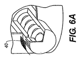
図6には、加熱された表面40の2つの実施態様が示してある。図6Aでは、加熱された表面40はスクリーン材料で形成されている。図6Bでは、加熱された表面40は隙間のない材料で形成されている。スクリーン材料は径方向に位置する開口部に関して図示してあるが、図1に示したように軸方向に位置する加熱された表面40も、隙間がないようにすること、またはスクリーンに存在するような開口部を持つようにできることが理解されよう。スクリーンという用語は、本発明が繊維またはワイヤーを織って作ったスクリーンに限定されることを意味するのではなく、実質的に開放された部分を有する任意の材料(例えば孔の開いた金属)を意味する。加熱された表面40と開口部35の距離は、一般に、千分の1インチの数倍にすぎない。図は、見やすくするため、実際の縮尺通りには描かれていない。
In FIG. 6, two embodiments of the
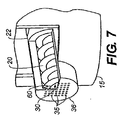
ここで図7を参照する。ワイパー60が回転可能なスクリュー20の一端に位置していて、回転可能なスクリュー20とともに回転する。ワイパー60は、開口部35を有する部材36と接触している。回転可能なスクリュー20が回転すると粉末が供給位置30に供給され、その位置では、ワイパー60が回転することによってワイパー60と部材36の間で材料が一点に集まってくさびを形成するため、粉末に対してスクリュー単独の場合よりも大きな力を与えることができ、その結果として、粉末は、非常に小さな開口部でさえ通過する。粉末はこのように非常に大きな圧力で圧縮されるため、開口部35から出てくる材料は、開口部35と加熱された表面40を隔てる距離にまたがるブリッジを形成することができる(図6Aと図6Bを参照のこと)。ワイパー60は回転可能なスクリュー20と一体化した状態を図示してあるが、当業者には、ワイパー60と回転可能なスクリュー20を独立に形成できることが明らかなはずである。ワイパー60と回転可能なスクリュー20を別々に駆動する場合には、両者を独立な速度で回転させることや、互いに反対の方向に回転させることができる。ワイパー60は軸方向を向いた開口部を利用する構成について示してあるが、当業者には、径方向に並んだ穴や傾斜した穴でワイパー60が動作する構成も可能であることは明らかであろう。
Reference is now made to FIG. The
図8に別の構成を示してある。スクリュー収容部22は、容器15の内部で鉛直方向を向いている。したがって回転可能なスクリュー20は向きが水平方向に限定されることはなく、任意の方向を向けることができる。
FIG. 8 shows another configuration. The
図8には、加熱された表面40がるつぼ(気化装置で用いる場合にはボートと呼ばれることがしばしばある)によって提供されることが示されている。したがって加熱された表面は、スクリーンに限定されたり、熱伝導性材料の薄いシートに限定されたりすることはなく、材料を瞬間的に気化させてスクリュー収容部22上の開口部35から出て行かせるのに十分な温度に維持できるのであれば、任意の形態が可能である。
FIG. 8 shows that the
図9では、撹拌用スクリュー75が容器15に組み込まれている。撹拌用スクリュー75が回転すると粉末材料がぎっしり詰まった状態が緩和され、流体様の挙動が増える。さらに、振動性アクチュエータ80がじょうご85に取り付けられている。じょうご85が材料をガイドする一方で、振動性アクチュエータ80は材料が固まってじょうごが詰まることを減らす。
In FIG. 9, a stirring
本発明を有機材料を用いて説明してきたが、本発明は、任意の粉末材料または粒子状材料の気化に適している。 Although the present invention has been described using organic materials, the present invention is suitable for vaporizing any powder or particulate material.
5 供給装置
10 有機材料
15 容器
20 回転可能なスクリュー
22 スクリュー収容部
24 スクリュー収容部の開口部
25 供給路
30 供給位置
35 開口部
36 部材
40 加熱された表面
45 モータ
50 センサー
55 制御装置
60 ワイパー
65 熱伝導路
70 ヒート・シンク
75 撹拌用スクリュー
80 振動性アクチュエータ
85 じょうご
5 Feeding device
10 Organic materials
15 containers
20 rotatable screw
22 Screw housing
24 Screw housing opening
25 Supply channel
30 Supply position
35 opening
36 parts
40 heated surface
45 Motor
50 sensors
55 Control unit
60 wipers
65 Heat transfer path
70 heat sink
75 Stirring screw
80 Vibration actuator
85 funnel
Claims (4)
(a)少なくとも1つの成分を含む粉末有機材料または粒子状有機材料を容器に供給するステップと;
(b)その容器から粉末有機材料または粒子状有機材料を受け取る位置に配置された回転可能なスクリューを用意し、そのスクリューが回転することにより、その粉末有機材料または粒子状有機材料を供給路に沿って、部材を含む供給位置まで移動させるステップと;
(c)その供給位置の該部材に複数の開口部を設け、その供給位置でスクリューが回転したときに発生する圧力によって上記の粉末有機材料または粒子状有機材料を制御された状態で該部材の開口部から上記加熱された表面へと移動させた後に、当該加熱された表面において当該有機材料を蒸発させるステップを含む方法。 A method of depositing an organic thin film layer of an OLED by physical vapor deposition by metering a powdered organic material or particulate organic material onto a heated surface, comprising:
(A) supplying a powdered organic material or particulate organic material comprising at least one component to the container;
(B) A rotatable screw arranged at a position for receiving the powder organic material or the particulate organic material from the container is prepared, and the powder organic material or the particulate organic material is supplied to the supply path by rotating the screw. And moving along a supply position including the member;
(C) The member at the supply position is provided with a plurality of openings, and the powder organic material or the particulate organic material is controlled by the pressure generated when the screw rotates at the supply position. after the opening is moved to the heated surface, the method comprising in the heated surface Ru evaporated the organic material.
(a)少なくとも1つの成分を含む粉末有機材料または粒子状有機材料を収容した容器を備え;
(b)その容器から粉末有機材料または粒子状有機材料を受け取る位置に配置された回転可能なスクリューを備え、そのスクリューが回転することにより、その粉末有機材料または粒子状有機材料が供給路に沿って、部材を含む供給位置まで移動し;
(c)その供給位置の該部材に複数の開口部を備え;
(d)上記開口部と上記回転可能なスクリューの間に配置されていて圧力を発生させる回転可能なワイパー部材を備え、その圧力により、上記の粉末有機材料または粒子状有機材料が、制御された状態で該部材の開口部を通過して上記加熱された表面へと移動した後に、当該加熱された表面において当該有機材料が蒸発する装置。 An apparatus for depositing an organic thin film layer of an OLED by physical vapor deposition by metering powdered organic material or particulate organic material onto a heated surface,
(A) a container containing a powdered organic material or a particulate organic material containing at least one component;
(B) A rotatable screw disposed at a position for receiving the powder organic material or the particulate organic material from the container is provided, and the powder organic material or the particulate organic material is moved along the supply path by rotating the screw. Move to the supply position containing the member;
(C) the member at the supply position is provided with a plurality of openings;
(D) A rotatable wiper member that is arranged between the opening and the rotatable screw and generates pressure is controlled by the pressure, and the powder organic material or the particulate organic material is controlled by the pressure. passes through the opening of the member after moving to the heated surface in the state, the heated device the organic material you evaporate at the surface.
Applications Claiming Priority (3)
| Application Number | Priority Date | Filing Date | Title |
|---|---|---|---|
| US11/050,924 US7625601B2 (en) | 2005-02-04 | 2005-02-04 | Controllably feeding organic material in making OLEDs |
| US11/050,924 | 2005-02-04 | ||
| PCT/US2006/003040 WO2006083734A2 (en) | 2005-02-04 | 2006-01-30 | Controllably feeding organic material in making oleds |
Publications (3)
| Publication Number | Publication Date |
|---|---|
| JP2008530733A JP2008530733A (en) | 2008-08-07 |
| JP2008530733A5 JP2008530733A5 (en) | 2009-03-12 |
| JP5551336B2 true JP5551336B2 (en) | 2014-07-16 |
Family
ID=36587179
Family Applications (1)
| Application Number | Title | Priority Date | Filing Date |
|---|---|---|---|
| JP2007554147A Active JP5551336B2 (en) | 2005-02-04 | 2006-01-30 | Controllable supply of organic materials in the manufacture of OLEDs |
Country Status (5)
| Country | Link |
|---|---|
| US (1) | US7625601B2 (en) |
| EP (1) | EP1844177B1 (en) |
| JP (1) | JP5551336B2 (en) |
| DE (1) | DE602006005335D1 (en) |
| WO (1) | WO2006083734A2 (en) |
Families Citing this family (33)
| Publication number | Priority date | Publication date | Assignee | Title |
|---|---|---|---|---|
| US7213347B2 (en) * | 2005-05-03 | 2007-05-08 | Eastman Kodak Company | Metering material to promote rapid vaporization |
| US20060286405A1 (en) | 2005-06-17 | 2006-12-21 | Eastman Kodak Company | Organic element for low voltage electroluminescent devices |
| US20070257394A1 (en) * | 2006-05-08 | 2007-11-08 | Maxwell Technologies, Inc. | Feeder for Agglomerating Particles |
| JP5179739B2 (en) * | 2006-09-27 | 2013-04-10 | 東京エレクトロン株式会社 | Vapor deposition apparatus, vapor deposition apparatus control apparatus, vapor deposition apparatus control method, and vapor deposition apparatus usage method |
| WO2008105287A1 (en) * | 2007-02-28 | 2008-09-04 | Ulvac, Inc. | Deposition source, deposition apparatus and method for forming organic thin film |
| WO2008117690A1 (en) * | 2007-03-26 | 2008-10-02 | Ulvac, Inc. | Evaporation source, vapor deposition apparatus and method of film formation |
| JP5282038B2 (en) * | 2007-09-10 | 2013-09-04 | 株式会社アルバック | Vapor deposition equipment |
| JP4974832B2 (en) * | 2007-09-10 | 2012-07-11 | 株式会社アルバック | Vapor deposition source, vapor deposition equipment |
| JP5374373B2 (en) * | 2007-09-10 | 2013-12-25 | 株式会社アルバック | Organic material vapor generating device, film forming source, organic EL film forming device |
| US8076009B2 (en) * | 2007-10-26 | 2011-12-13 | Global Oled Technology, Llc. | OLED device with fluoranthene electron transport materials |
| US8431242B2 (en) * | 2007-10-26 | 2013-04-30 | Global Oled Technology, Llc. | OLED device with certain fluoranthene host |
| US8420229B2 (en) * | 2007-10-26 | 2013-04-16 | Global OLED Technologies LLC | OLED device with certain fluoranthene light-emitting dopants |
| JP4974877B2 (en) * | 2007-12-28 | 2012-07-11 | 株式会社アルバック | Deposition source, deposition system |
| JP4996452B2 (en) * | 2007-12-28 | 2012-08-08 | 株式会社アルバック | Deposition source, deposition system |
| US7883583B2 (en) * | 2008-01-08 | 2011-02-08 | Global Oled Technology Llc | Vaporization apparatus with precise powder metering |
| US7947974B2 (en) * | 2008-03-25 | 2011-05-24 | Global Oled Technology Llc | OLED device with hole-transport and electron-transport materials |
| JP5553763B2 (en) | 2008-09-24 | 2014-07-16 | 出光興産株式会社 | Composite organic electroluminescent material |
| US7931975B2 (en) * | 2008-11-07 | 2011-04-26 | Global Oled Technology Llc | Electroluminescent device containing a flouranthene compound |
| US8088500B2 (en) * | 2008-11-12 | 2012-01-03 | Global Oled Technology Llc | OLED device with fluoranthene electron injection materials |
| US8048230B2 (en) * | 2008-11-14 | 2011-11-01 | Global Oled Technology Llc | Metering and vaporizing particulate material |
| US8062427B2 (en) * | 2008-11-14 | 2011-11-22 | Global Oled Technology Llc | Particulate material metering and vaporization |
| US7972443B2 (en) * | 2008-11-14 | 2011-07-05 | Global Oled Technology Llc | Metering of particulate material and vaporization thereof |
| US7968215B2 (en) * | 2008-12-09 | 2011-06-28 | Global Oled Technology Llc | OLED device with cyclobutene electron injection materials |
| US20100206234A1 (en) * | 2009-02-17 | 2010-08-19 | Michael Long | Simplified powder feeding and vaporization apparatus |
| US8147989B2 (en) * | 2009-02-27 | 2012-04-03 | Global Oled Technology Llc | OLED device with stabilized green light-emitting layer |
| US8425801B2 (en) * | 2009-04-10 | 2013-04-23 | Idemitsu Kosan Co., Ltd. | Composite organic electroluminescent material and production method thereof |
| JP4974036B2 (en) * | 2009-11-19 | 2012-07-11 | 株式会社ジャパンディスプレイセントラル | Manufacturing method of organic EL device |
| KR101379646B1 (en) * | 2009-12-09 | 2014-03-28 | 가부시키가이샤 알박 | Film forming device for organic thin films, and method for forming film using organic materials |
| US20120028393A1 (en) * | 2010-12-20 | 2012-02-02 | Primestar Solar, Inc. | Vapor deposition apparatus and process for continuous deposition of a doped thin film layer on a substrate |
| DE102011051263B4 (en) * | 2011-06-22 | 2022-08-11 | Aixtron Se | Device for aerosol generation and deposition of a light-emitting layer |
| CN104789945B (en) * | 2015-04-01 | 2017-05-24 | 华东师范大学 | Vapor transport deposition device of solar battery absorbing layer |
| KR102344996B1 (en) * | 2017-08-18 | 2021-12-30 | 삼성전자주식회사 | Unit for supplying precursor, substrate processing apparatus and method for manufacturing semiconductor device using the same |
| CN117355364A (en) | 2021-05-21 | 2024-01-05 | 默克专利有限公司 | Method for continuously purifying at least one functional material and device for continuously purifying at least one functional material |
Family Cites Families (17)
| Publication number | Priority date | Publication date | Assignee | Title |
|---|---|---|---|---|
| US2447789A (en) * | 1945-03-23 | 1948-08-24 | Polaroid Corp | Evaporating crucible for coating apparatus |
| SU779441A1 (en) * | 1978-07-31 | 1980-11-15 | Институт Механики Металлополимерных Систем Ан Белорусской Сср | Dosing feeder |
| DE3530106A1 (en) * | 1985-08-23 | 1987-02-26 | Kempten Elektroschmelz Gmbh | VAPORIZATION MATERIAL FOR VAPORIZING INORGANIC COMPOUNDS BY MEANS OF A PHOTON-GENERATING RADIATION HEATING SOURCE IN CONTINUOUSLY OPERATED VACUUM VACUUM DEVICES |
| US4885211A (en) * | 1987-02-11 | 1989-12-05 | Eastman Kodak Company | Electroluminescent device with improved cathode |
| US4769292A (en) * | 1987-03-02 | 1988-09-06 | Eastman Kodak Company | Electroluminescent device with modified thin film luminescent zone |
| EP0585848A1 (en) | 1992-09-02 | 1994-03-09 | Hoechst Aktiengesellschaft | Method and apparatus for thin film formation by CVD |
| DE4325514C1 (en) * | 1993-07-29 | 1994-10-27 | Schaaf Technologie Gmbh | Cooking extruders for the production of thermally treated biopolymers and processes for cooking extrusion of biopolymers |
| US5945163A (en) * | 1998-02-19 | 1999-08-31 | First Solar, Llc | Apparatus and method for depositing a material on a substrate |
| JP2000068055A (en) | 1998-08-26 | 2000-03-03 | Tdk Corp | Evaporation source for organic el element, manufacturing device for organic el element using the same and manufacture thereof |
| JP2000248358A (en) * | 1999-03-01 | 2000-09-12 | Casio Comput Co Ltd | Vapor deposition device and vapor deposition method |
| IT1310745B1 (en) * | 1999-11-26 | 2002-02-22 | Lawer Spa | DEVICE FOR DOSED DISPENSING OF SLIDING PRODUCTS. |
| JP3921955B2 (en) * | 2000-05-12 | 2007-05-30 | 株式会社デンソー | Ceramic molding extrusion equipment |
| ITMI20010995A1 (en) * | 2001-05-15 | 2002-11-15 | Getters Spa | CESIUM DISPENSERS AND PROCESS FOR THEIR USE |
| US20030168013A1 (en) * | 2002-03-08 | 2003-09-11 | Eastman Kodak Company | Elongated thermal physical vapor deposition source with plural apertures for making an organic light-emitting device |
| JP2003293121A (en) * | 2002-04-05 | 2003-10-15 | Cluster Ion Beam Technology Kk | Vapor deposition crucible having means for supplying vapor deposition material |
| US7118783B2 (en) * | 2002-06-26 | 2006-10-10 | Micron Technology, Inc. | Methods and apparatus for vapor processing of micro-device workpieces |
| US7339139B2 (en) * | 2003-10-03 | 2008-03-04 | Darly Custom Technology, Inc. | Multi-layered radiant thermal evaporator and method of use |
-
2005
- 2005-02-04 US US11/050,924 patent/US7625601B2/en active Active
-
2006
- 2006-01-30 DE DE602006005335T patent/DE602006005335D1/en active Active
- 2006-01-30 JP JP2007554147A patent/JP5551336B2/en active Active
- 2006-01-30 WO PCT/US2006/003040 patent/WO2006083734A2/en active Application Filing
- 2006-01-30 EP EP06719753A patent/EP1844177B1/en active Active
Also Published As
| Publication number | Publication date |
|---|---|
| US7625601B2 (en) | 2009-12-01 |
| WO2006083734A2 (en) | 2006-08-10 |
| JP2008530733A (en) | 2008-08-07 |
| EP1844177B1 (en) | 2009-02-25 |
| US20060177576A1 (en) | 2006-08-10 |
| DE602006005335D1 (en) | 2009-04-09 |
| EP1844177A2 (en) | 2007-10-17 |
| WO2006083734A3 (en) | 2006-10-19 |
Similar Documents
| Publication | Publication Date | Title |
|---|---|---|
| JP5551336B2 (en) | Controllable supply of organic materials in the manufacture of OLEDs | |
| JP5237088B2 (en) | Controllable supply of powdered or granular material | |
| JP6639580B2 (en) | Evaporator, deposition arrangement, deposition device and method of operating these | |
| JP4782219B2 (en) | Vacuum deposition equipment | |
| JP2007500794A (en) | Thin film evaporation evaporator | |
| JP2008169456A (en) | Vacuum deposition system | |
| JP5139287B2 (en) | How to vaporize materials at a constant rate | |
| JP5032466B2 (en) | Material metering to facilitate rapid vaporization | |
| EP2278044B1 (en) | Controlling the application of vaporized organic material | |
| US8012537B2 (en) | Controlling the vaporization of organic material | |
| TW201544616A (en) | Vacuum evaporation apparatus | |
| KR20070047201A (en) | A molecular beam source for use of thin-film accumulation and a method for controlling volume of molecular beam | |
| JP2008530734A (en) | Supplying particulate material to heated surfaces | |
| JPWO2006075401A1 (en) | Evaporation source and vapor deposition equipment | |
| JP2014152365A (en) | Vacuum evaporation system | |
| JP2021181606A (en) | Evaporation source device, evaporator, and method for controlling evaporation source device |
Legal Events
| Date | Code | Title | Description |
|---|---|---|---|
| A521 | Request for written amendment filed |
Free format text: JAPANESE INTERMEDIATE CODE: A523 Effective date: 20090120 |
|
| A621 | Written request for application examination |
Free format text: JAPANESE INTERMEDIATE CODE: A621 Effective date: 20090120 |
|
| A711 | Notification of change in applicant |
Free format text: JAPANESE INTERMEDIATE CODE: A711 Effective date: 20100805 |
|
| A131 | Notification of reasons for refusal |
Free format text: JAPANESE INTERMEDIATE CODE: A131 Effective date: 20111220 |
|
| A601 | Written request for extension of time |
Free format text: JAPANESE INTERMEDIATE CODE: A601 Effective date: 20120319 |
|
| A602 | Written permission of extension of time |
Free format text: JAPANESE INTERMEDIATE CODE: A602 Effective date: 20120327 |
|
| A521 | Request for written amendment filed |
Free format text: JAPANESE INTERMEDIATE CODE: A523 Effective date: 20120619 |
|
| A131 | Notification of reasons for refusal |
Free format text: JAPANESE INTERMEDIATE CODE: A131 Effective date: 20121113 |
|
| A601 | Written request for extension of time |
Free format text: JAPANESE INTERMEDIATE CODE: A601 Effective date: 20130213 |
|
| A602 | Written permission of extension of time |
Free format text: JAPANESE INTERMEDIATE CODE: A602 Effective date: 20130220 |
|
| A521 | Request for written amendment filed |
Free format text: JAPANESE INTERMEDIATE CODE: A523 Effective date: 20130513 |
|
| A131 | Notification of reasons for refusal |
Free format text: JAPANESE INTERMEDIATE CODE: A131 Effective date: 20131203 |
|
| A521 | Request for written amendment filed |
Free format text: JAPANESE INTERMEDIATE CODE: A523 Effective date: 20140228 |
|
| TRDD | Decision of grant or rejection written | ||
| A01 | Written decision to grant a patent or to grant a registration (utility model) |
Free format text: JAPANESE INTERMEDIATE CODE: A01 Effective date: 20140422 |
|
| A61 | First payment of annual fees (during grant procedure) |
Free format text: JAPANESE INTERMEDIATE CODE: A61 Effective date: 20140522 |
|
| R150 | Certificate of patent or registration of utility model |
Ref document number: 5551336 Country of ref document: JP Free format text: JAPANESE INTERMEDIATE CODE: R150 |
|
| R250 | Receipt of annual fees |
Free format text: JAPANESE INTERMEDIATE CODE: R250 |
|
| R250 | Receipt of annual fees |
Free format text: JAPANESE INTERMEDIATE CODE: R250 |
|
| R250 | Receipt of annual fees |
Free format text: JAPANESE INTERMEDIATE CODE: R250 |
|
| R250 | Receipt of annual fees |
Free format text: JAPANESE INTERMEDIATE CODE: R250 |
|
| R250 | Receipt of annual fees |
Free format text: JAPANESE INTERMEDIATE CODE: R250 |
|
| R250 | Receipt of annual fees |
Free format text: JAPANESE INTERMEDIATE CODE: R250 |
|
| R250 | Receipt of annual fees |
Free format text: JAPANESE INTERMEDIATE CODE: R250 |