JP5269552B2 - Selective separation device for waste oil and waste water containing solids - Google Patents
Selective separation device for waste oil and waste water containing solids Download PDFInfo
- Publication number
- JP5269552B2 JP5269552B2 JP2008286023A JP2008286023A JP5269552B2 JP 5269552 B2 JP5269552 B2 JP 5269552B2 JP 2008286023 A JP2008286023 A JP 2008286023A JP 2008286023 A JP2008286023 A JP 2008286023A JP 5269552 B2 JP5269552 B2 JP 5269552B2
- Authority
- JP
- Japan
- Prior art keywords
- waste
- waste oil
- ceiling
- waste water
- open container
- Prior art date
- Legal status (The legal status is an assumption and is not a legal conclusion. Google has not performed a legal analysis and makes no representation as to the accuracy of the status listed.)
- Expired - Fee Related
Links
- 239000002699 waste material Substances 0.000 title claims description 135
- 239000002351 wastewater Substances 0.000 title claims description 75
- 239000007787 solid Substances 0.000 title claims description 52
- 238000000926 separation method Methods 0.000 title claims description 45
- 238000003825 pressing Methods 0.000 claims description 2
- 238000000034 method Methods 0.000 description 9
- 239000007788 liquid Substances 0.000 description 5
- 239000003463 adsorbent Substances 0.000 description 4
- 235000012149 noodles Nutrition 0.000 description 4
- 239000002910 solid waste Substances 0.000 description 4
- 240000007594 Oryza sativa Species 0.000 description 2
- 235000007164 Oryza sativa Nutrition 0.000 description 2
- 235000009508 confectionery Nutrition 0.000 description 2
- 238000000354 decomposition reaction Methods 0.000 description 2
- 244000005700 microbiome Species 0.000 description 2
- 239000012466 permeate Substances 0.000 description 2
- 235000009566 rice Nutrition 0.000 description 2
- 239000004071 soot Substances 0.000 description 2
- 235000014347 soups Nutrition 0.000 description 2
- 238000004065 wastewater treatment Methods 0.000 description 2
- 241000196324 Embryophyta Species 0.000 description 1
- 240000008620 Fagopyrum esculentum Species 0.000 description 1
- 235000009419 Fagopyrum esculentum Nutrition 0.000 description 1
- 230000002411 adverse Effects 0.000 description 1
- 230000000994 depressogenic effect Effects 0.000 description 1
- 238000005516 engineering process Methods 0.000 description 1
- 230000007613 environmental effect Effects 0.000 description 1
- 235000013410 fast food Nutrition 0.000 description 1
- 238000001914 filtration Methods 0.000 description 1
- 238000007667 floating Methods 0.000 description 1
- 235000013305 food Nutrition 0.000 description 1
- 238000009434 installation Methods 0.000 description 1
- 238000004519 manufacturing process Methods 0.000 description 1
- 238000011176 pooling Methods 0.000 description 1
- 238000005086 pumping Methods 0.000 description 1
- 238000000746 purification Methods 0.000 description 1
- 230000001105 regulatory effect Effects 0.000 description 1
- 239000013049 sediment Substances 0.000 description 1
- 239000010865 sewage Substances 0.000 description 1
- 238000003860 storage Methods 0.000 description 1
- XLYOFNOQVPJJNP-UHFFFAOYSA-N water Substances O XLYOFNOQVPJJNP-UHFFFAOYSA-N 0.000 description 1
- 239000003403 water pollutant Substances 0.000 description 1
Images


Landscapes
- Removal Of Floating Material (AREA)
- Filtration Of Liquid (AREA)
Description
本発明は、廃油分や廃固形分などを含有する廃水から廃油分をまず選択的に分離する簡易な装置に関する。 The present invention relates to a simple apparatus that selectively separates waste oil from waste water containing waste oil or solid waste.
飲食料理店、ファーストフード店、レストラン、ホテル、食品加工場などの小規模事業所における厨房廃水には、様々の水質汚濁物質が含まれている。このような廃水を何ら処理することなく排水すると、廃水中の廃油分などが排水管に付着して固まり、詰まらせたりするだけでなく、合併処理槽や下水処理場での水の浄化処理を困難にし、また、環境に悪影響を及ぼし、法的規制を受けて、営業を続けることができなくなる事態ともなり得る。
そこで、廃油分や沈殿物、浮遊物などの廃固形分を含む廃水を排出事業所単位で処理する方法、装置が種々提案されており、これらの技術は大きく分けて2つのグループに分類される。
すなわち、第1のグループは、廃水中の廃油分などを微生物で分解処理する方法、装置である。しかし、この方法、装置では、廃油分分解の速度が遅いため分解効率が悪く、また、微生物の管理に配慮しなければならず、複雑な設備が必要であった。
第2のグループは、廃水をプールし、浮いている上層の廃油分を汲み出したり、吸着剤で吸着してロ過する等により、廃水中の廃油分などを物理的に除去する方法、装置である。しかし、この方法、装置では、廃水(のプール)から悪臭が発生したり、廃油分の分離、除去が不完全となりやすく、また、大型のシステム、設備が必要であった。
これら従来技術の問題点を解決するため、特許文献1には、廃油分は透過するが油吸着剤は透過しない壁面で形成された油吸着剤を収容する油吸着槽を備えた含油廃水処理装置が開示されている。
しかしながら、この含油廃水処理装置は、従来の装置にくらべれば比較的簡易な装置と言えるが、油吸着剤の消耗などのランニングコストや装置の構造がなお比較的複雑であるため、零細事業所にとっては装置の価格が高すぎるといった主に経済性の面から、依然として零細、小規模な事業所飲食店などでは直ちに採用するには負担が重かった。
Therefore, various methods and devices for treating waste water containing waste oil, sediment, suspended solids, and other waste solids have been proposed for each waste establishment, and these technologies can be broadly classified into two groups. .
That is, the first group is a method and apparatus for decomposing waste oil in wastewater with microorganisms. However, in this method and apparatus, the decomposition rate of waste oil is slow, so the decomposition efficiency is poor, and management of microorganisms must be taken into consideration, and complicated equipment is required.
The second group is a method and equipment that physically removes waste oil etc. in wastewater by pooling wastewater, pumping up the floating waste oil in the upper layer, or adsorbing and filtering it with an adsorbent. is there. However, in this method and apparatus, malodors are generated from the waste water (pool), and the separation and removal of the waste oil tends to be incomplete, and a large system and equipment are required.
In order to solve these problems of the prior art,
However, although this oil-containing wastewater treatment device can be said to be a relatively simple device compared to conventional devices, the running costs such as the consumption of oil adsorbents and the structure of the device are still relatively complicated, which makes it difficult for small businesses. However, the cost of the equipment was too high, mainly due to economic reasons, and it was still a burden to adopt it immediately in small and small business establishments.
最近の環境問題に対する社会の流れに対応して、廃油及び廃固形分含有廃水を排水する更に零細、小規模の事業所においても採用可能な、効率的で更に簡易、経済的な分離(処理)装置が要望されている。特に、うどん店やそば店などにおいては、排水中に廃固形分として粉状のものが多量に含まれており、これらの分離、処理も併せて可能な装置が求められている。 Efficient, simpler, more economical separation (treatment) that can be adopted by even smaller and small-scale establishments that drain waste oil and waste solids containing wastewater in response to the recent trend of environmental issues. An apparatus is desired. In particular, udon shops and soba shops contain a large amount of powdery waste solids in the drainage, and there is a need for an apparatus capable of separating and treating them.
本発明は、廃油分や様々の形状、性状の廃固形分などを含有する廃水を排出する零細、小規模事業所等において、廃水から廃油分や廃固形分を効率的に分離するための、構造の簡易な小型の装置を提供することを目的とする。 The present invention is a method for efficiently separating waste oil and solid waste from waste water in a small-scale, small-scale business office or the like that discharges waste water containing waste oil or various shapes and properties of solid waste. An object is to provide a small-sized device with a simple structure.
前記目的を達成するため、本発明は、底面に開閉弁付き廃油又は廃水排出管を備えた天井開放容器と、該天井開放容器の廃油又は廃水排出管に連結する廃油層分の選択的排出装置とからなる、廃油及び廃固形分含有廃水の選択分離装置であって、前記の廃油層分の選択的排出装置が、側面の縦長方向に下端部から所定間隔で複数の栓付き孔と下端部に前記廃油又は廃水排出管への連結部と上部に空気抜き孔と上端管口部に貫通孔を備えたカバーを設けた透明管と、上端部につまみ部と上部にストッパーピンと下端に透明管の下端開口部を開閉する栓を設けたシャフトとからなり、更にシャフトのつまみ部と透明管のカバーとの間にバネを設けてなり、かつ、該つまみ部を押圧しながら又は押圧を解除するように回転させることによりシャフトをバネ力を利用して押し下げ又は上昇させ、ストッパーピンをカバーの下側又は上側に係留させて前記廃油又は廃水排出管に連結された透明管下端開口部の栓を開閉させるように構成すると共に、天井開放容器内に貯留した廃油含有廃水の廃油層分と廃水層分との境界面のすぐ上の栓付き孔を少なくとも含む前記境界面より上の栓付き孔から栓を離脱させることにより廃油層分のみを天井開放容器外に流出させることができるように構成したこと、を特徴とする前記選択分離装置である。
In order to achieve the above object, the present invention provides a ceiling open container having a waste oil or waste water discharge pipe with an open / close valve on the bottom surface, and a selective drainage device for a waste oil layer connected to the waste oil or waste water discharge pipe of the ceiling open container. consisting of, waste oil and a selective separator waste solids containing waste water, the waste layer portion of the selective discharge device is, stoppered hole and the lower end of the multiple at predetermined intervals from the lower end in the longitudinal direction of the side surface A transparent pipe with a connecting part to the waste oil or waste water discharge pipe at the upper part, a cover with an air vent hole at the upper part and a through hole at the upper pipe part, a knob part at the upper part, a stopper pin at the upper part, and a transparent pipe at the lower part The shaft is provided with a plug for opening and closing the lower end opening of the shaft, and further, a spring is provided between the knob portion of the shaft and the cover of the transparent tube, and the pressure is released while pressing the knob portion. By rotating the shaft so that Spring force by utilizing depressed or raised, and with a stopper pin by anchored to the lower side or upper side of the cover configured to be opened and closed the plug of the waste oil or transparent pipe connected to the waste water discharge pipe lower end opening, Waste oil layer by removing the plug from the plug hole above the boundary surface including at least a plug hole immediately above the boundary surface between the waste oil layer and the waste water layer portion of the waste oil-containing waste water stored in the ceiling open container The selective separation device according to
本発明は、前記天井開放容器の開放天井面に設置され、その上方から流し込まれる廃油及び廃固形分含有廃水を分離する1以上の固形分分離貯留器を更に備えてなる、前記の廃油及び廃固形分含有廃水の選択分離装置である。 The present invention further includes at least one solid content separation and storage device that is installed on an open ceiling surface of the above open ceiling container and separates waste oil and waste solid-containing waste water poured from above. This is a selective separation device for solid content-containing wastewater.
本発明は、前記天井開放容器の開放天井面と前記固形分分離貯留器との間に設置して、前記の1以上の固形分分離貯留器を載置する支持体を更に備えてなる、前記の廃油及び廃固形分含有廃水の選択分離装置である。 The present invention further comprises a support that is installed between the open ceiling surface of the ceiling open container and the solid content separation reservoir, and on which the one or more solid content separation reservoirs are placed, This is a selective separation device for waste oil and waste water containing waste solids.
また本発明は、前記天井開放容器を載置して支持するスタンドを更に備えてなる、前記の各廃油及び廃固形分含有廃水分離装置である。 Moreover, this invention is said each waste oil and waste solid content waste water separation apparatus which is further provided with the stand which mounts and supports the said ceiling open container.
本発明により初めて、廃油分や様々の形状、性状の廃固形分などを含有する廃水を排出する零細、小規模事業所等において、廃水から廃油分や廃固形分を効率的に分離するための、構造の簡易な小型の装置を提供することが可能となった。 For the first time according to the present invention, in order to efficiently separate waste oil and waste solids from wastewater in a small-scale, small-scale establishment that discharges wastewater containing waste oil and various shapes and properties of solid waste. Thus, it is possible to provide a small-sized device with a simple structure.
以下、本発明の実施の形態を図面に基づいて説明する。
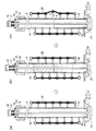
図2は、本発明の第1実施例の廃油及び廃固形分含有廃水の選択分離装置の斜視図であり、廃油層分の選択的排出装置を天井開放容器内に設置する前(a)と設置した後(b)とを示している。図3は、図2における廃油層分の選択的排出装置の使用方法を説明する図面(廃油層分の選択的排出装置の側断面図)である。
Hereinafter, embodiments of the present invention will be described with reference to the drawings.
FIG. 2 is a perspective view of the selective separation device for waste oil and waste solids-containing waste water according to the first embodiment of the present invention (a) before installing the selective drainage device for the waste oil layer in the open ceiling container. (B) after installation. FIG. 3 is a drawing (a side sectional view of the selective drainage device for waste oil layer) for explaining how to use the selective drainage device for waste oil layer in FIG. 2.
図2に示す本発明の第1実施例の廃油及び廃固形分含有廃水の選択分離装置は、底面に開閉弁付き廃油又は廃水排出管3を備えた天井開放容器1と、該天井開放容器1の廃油又は廃水排出管3に連結する廃油層分の選択的排出装置8と、スタンド7とからなる基本構成である。
The selective separation apparatus for waste oil and waste solids containing waste water according to the first embodiment of the present invention shown in FIG. 2 includes a ceiling
この開閉弁付き廃油又は廃水排出管3は、天井開放容器1の底面に設けられている。具体的には、天井開放容器1の底面中央部の廃油、廃水排出口では、その排出管4の入口は次第に細くなるテーパー状となっており、廃油層分の選択的排出装置8の連結部12に密接に連結される構造となっている。排出管4には開閉弁5が設けられている。
The waste oil or waste
廃油層分の選択的排出装置8の基本構成は、透明管9とシャフト14とバネ17とからなり、シャフト14は透明管9内に収容されて、バネ17の力により上下動し、その作動が制御される構造である。
The basic structure of the selective discharge device 8 for the waste oil layer is composed of a
透明管9の対向両側面の各縦長方向には、廃油層分の選択的排出装置8のバランスなどの点から、下端部から所定間隔でそれぞれ多数の栓10付き孔11が各々互い違いに設けられている。透明管9の下端部には廃油又は廃水排出管3への連結部12が設けられており、また、その上端管口部には貫通孔19を備えたカバー22が設けられており、更に、透明管9の上部には透明管9内外への廃油層分又は廃水層分の流入、流出を円滑に行うための空気抜き孔13が設けられている。孔11と栓10は互いに挿入しやすく、密接するように、透明管9の内側に向かって次第に口細となるテーパー状となっている。栓10同士は、互いに離散するのを防止するため、相互に連続的にチェーン20により連結されている。連結部12は、廃油又は廃水排出管3へ挿入しやすく、密接するように、側面が下端に近いほど口細となるテーパー部12−1となっており、その上部は天井開放容器1との密閉性を確保するためフランジ部12−2が形成されている。
A plurality of holes 11 with
シャフト14の上端部にはつまみ部15が形成されており、また、その上部にはストッパーピン18が設けられており、更に、シャフト14の下端には透明管9の下端開口部16を開閉する栓21が形成されている。
シャフト14は、そのつまみ部15と透明管9の上端管口部のカバー22との間にバネ17を挟んで(介して)透明管9内に挿入されており、バネ17が配置されている位置より少し下部のシャフト14には、短いストッパーピン18がシャフト14に対して(十字状に)直交するように固設されている。透明管9の上端開口部のカバー22には、シャフト14とストッパーピン18のみが通過することができるように、シャフト14の直径とストッパーピン18の幅より僅かに大きい程度の貫通孔19が設けられている。そのため、シャフト14をつまみ部15により僅かに回転させると、ストッパーピン18は透明管9のカバー22の貫通孔19を通り抜けることができない構造となっている。
A
The
スタンド7は、四角枠の四隅にそれぞれ脚部と天井開放容器1止めを設けた構造であり、天井開放容器1の底面を支えて、開閉弁5を備えた排出管4の先端(排出)口を適当な高さ(位置)に保持して作業しやすくするためのものである。従って、このスタンド7は本発明においては必須ではないが、併用するのが好ましい。
The
本発明の第1実施例の他の態様では、前記の各廃油及び廃固形分含有廃水の選択分離装置に、天井開放容器1を保持するためのスタンド7を併用していないものである。
In another aspect of the first embodiment of the present invention, a
図1は、本発明の第2実施例の廃油及び廃固形分含有廃水の選択分離装置において廃油層分の選択的排出装置を除いた分解斜視図である。 FIG. 1 is an exploded perspective view of a selective separation device for waste oil and waste solids containing waste water according to a second embodiment of the present invention, excluding a selective discharge device for waste oil layer.
図1に示す本発明の第2実施例の廃油及び廃固形分含有廃水の選択分離装置は、底面に開閉弁付き廃油又は廃水排出管3を備えた天井開放容器1と、該天井開放容器1の廃油又は廃水排出管3に連結する廃油層分の選択的排出装置8(図示省略)と、1以上の固形分分離貯留器2と、(固形分分離貯留器(笊)用の)支持体6と、スタンド7とからなる基本構成である。すなわち、この廃油層分の選択的排出装置8は、前記の第1実施例の廃油及び廃固形分含有廃水の選択分離装置におけるものと同じものであり(図2及び3参照)、第2実施例の廃油及び廃固形分含有廃水の選択分離装置は、図2に示す前記第1実施例の廃油及び廃固形分含有廃水の選択分離装置に更に、1以上の固形分分離貯留器2と支持体6を併用した装置である。
The selective separation apparatus for waste oil and waste solids-containing waste water of the second embodiment of the present invention shown in FIG. 1 includes a ceiling
前記の1以上の固形分分離貯留器2は、具体的には例えば、目の粗い笊2−2と目の細かい笊2−1との組み合わせである。天井開放容器1の上に直接に或いは支持体6を介して目の細かい笊2−1を載せ、更にその上に目の粗い笊2−2を載せて使用するのが廃固形分の分離に効率的である。
例えば食べ残したうどん廃液を分離(処理)する場合などでは、天井開放容器1の上に載せた目の粗い笊2−2と目の細かい笊2−1の上から流し込んで、まず大きな多量の麺を目の粗い笊2−2で分け採り、次いで細切れとなった細かい麺を目の細かい笊2−1で分け採ることができ、麺(廃固形分)を確実に笊2上に確保することができる。
Specifically, the one or more solid content separation reservoirs 2 are, for example, a combination of a coarse candy 2-2 and a fine candy 2-1. For separation of waste solids, a fine jar 2-1 is placed directly on the
For example, in the case of separating (processing) the leftover udon waste liquid, it is poured from above the coarse jar 2-2 and the fine jar 2-1 placed on the
支持体6は、天井開放容器1の開放上面に設置して、天井開放容器1と1以上の固形分分離貯留器2との間に、前記の1以上の固形分分離貯留器(笊)2を安定的に載置するためのものである。支持体6は、天井開放容器1の開放天井より少し大きい四角形の枠状であり、その四隅は天井開放容器1の開放天井円周上に安定的に係止することができるように下向きに一旦屈曲した形状(構造)となっている。
この支持体6は、さまざまな大きさの笊2を天井開放容器1の上に安定的に載置することができるので、天井開放容器1の開放天井の大きさにかかわらず、各種の大きさ、形状の笊(固形分分離貯留器)2を使用することができる。
The
Since the
本発明の第2実施例の他の態様では、笊(固形分分離貯留器)2が天井開放容器1に載せるのにピッタリと適切な大きさである場合、前記の廃油及び廃固形分含有廃水の選択分離装置に、笊(固形分分離貯留器)2を保持するための支持体6を併用していないものである。
In another aspect of the second embodiment of the present invention, when the dredging (solid content separation / reservoir) 2 is of an appropriate size to be placed on the ceiling
(1)次に、本発明の前記第1実施例の廃油及び廃固形分含有廃水の選択分離装置を使用して、うどん店におけるうどん製造廃液の分離(処理)を例にとって説明する(図2及び3参照)。
まず、廃油層分の選択的排出装置8を使用して、天井開放容器1内に溜まっている廃油層分と廃水層分との境界面の(天井開放容器1底面からの)位置を測定する。すなわち、天井開放容器1内にある程度の廃油含有廃水が溜まってその浄化のために排出、移送する必要が生じたときに、まず廃油層分の選択的排出装置8のつまみ部15をシャフト下方に押しながら僅かづつ回転させて、ストッパーピン18を透明管9のカバー22に設けられている貫通孔19を通り抜けさせ、更につまみ部15を僅かに(シャフト下方に押しながら)回転させて、ストッパーピン18をカバー22の下側に係留させる。ストッパーピン18がカバー22の下側に係留された状態では、シャフト14下端の栓21は透明管9の下端開口部16より離れて、透明管9の下端開口部16は開いた状態となっている。この下端開口部16が開いた状態で選択的排出装置8を静かにゆっくりと天井開放容器1内に沈めて廃油又は廃水排出管3に連結する(図2(a)及び図3(a)参照)。次に、再びつまみ部15を僅かづつ回転させて、ストッパーピン18をバネ17の力によりシャフト14上向きに貫通孔19内を通り抜けさせ、更につまみ部15を僅かに回転させてストッパーピン18をカバー22の上側に係留させて、透明管9の下端開口部16を閉じる。栓21により透明管9の下端開口部16が閉じられた状態のままで廃油層分の選択的排出装置8を天井開放容器1内から引き上げて、透明管9の連結部12を透明管9の下端開口部16から離脱させる。透明管9内には廃油層分と廃水層分が天井開放容器1内におけるのと同じ層(位置)状態で入っており、透明管9の外側面から目視して、透明管9内における廃油層分と廃水層分との境界面の位置、すなわち、天井開放容器1内における廃油層分と廃水層分との境界面の(天井開放容器1底面からの)位置を測定する(図3(b)参照)。
次に、廃油層分と廃水層分との境界面からすぐ上の(位置の)透明管9の孔11に挿入されている栓10(或いはそれより上の全ての栓10)を抜いて、再度、廃油層分の選択的排出装置8を天井開放容器1内に沈めて、透明管9の連結部12を廃油又は廃水排出管3に連結する(図2(b)及び図3(c)参照)。そして、再びつまみ部15をシャフト下方に押しながら僅かに回転させて貫通孔19を通り抜けさせ、ストッパーピン18をカバー22の下側に係留させ、シャフト14下端の栓21を透明管9の下端開口部16より離れさせて、透明管9の下端開口部16を開いた状態とする。次いで開閉弁5を開くと、天井開放容器1内の廃油層分は透明管9の孔11を通って廃油又は廃水排出管3から流出する(図3(b)参照)。なお、透明管9の下端開口部16を開く前に廃油又は廃水排出管3の開閉弁5を開閉させて、予め透明管9の下端開口部16から排出管4内に存在する廃水層分を流出させておくのが好ましい。
その後、天井開放容器1内には粉体状廃固形分と廃水層分が残留しているので、天井開放容器1を傾斜させる等の方法で廃水層分を除去して粉体状廃固形分と分離させるか、或いは、粉体状廃固形分と廃水層分が残留している天井開放容器1内に更に継続して廃油及び廃固形分含有廃水を貯留させるのに使用する。
(1) Next, separation (treatment) of udon production waste liquid in an udon store will be described as an example using the selective separation apparatus for waste oil and waste solids-containing waste water of the first embodiment of the present invention (FIG. 2). And 3).
First, using the selective discharge device 8 for the waste oil layer, the position (from the bottom of the ceiling open container 1) of the boundary surface between the waste oil layer and the waste water layer accumulated in the ceiling
Next, the plug 10 (or all the
Thereafter, since the powdery waste solids and the wastewater layer remain in the ceiling
(2)更に、本発明の前記第2実施例の廃油及び廃固形分含有廃水の選択分離装置を使用して、うどん店における食べ残しうどん廃液の分離(処理)を例にとって説明する(図1〜3参照)。
開閉弁5を閉じた状態の天井開放容器1の上に載せた目の細かい笊2−1と更にその上の目の粗い笊2−2の上から食べ残したうどん廃液を流し込んで、食べ残し麺を笊2上に分離し、油混じりのスープを天井開放容器1内に溜める(図1参照)。少なくとも廃油分がある程度の量浮くほどの量の油混じりのスープが天井開放容器1に溜まったら、前記(1)の方法に従って、うどん廃液の分離(処理)を行う(図2及び3参照)。
(2) Further, separation (treatment) of uneaten udon waste liquid in a udon store will be described as an example using the waste oil and waste solid content waste water selective separation apparatus of the second embodiment of the present invention (FIG. 1). To 3).
Pour the leftover udon waste liquid from the fine rice cake 2-1 placed on the
1 天井開放容器
2 固形分分離貯留器(笊)
2−2 目の粗い笊
2−1 目の細かい笊
3 開閉弁付き廃油又は廃水排出管
4 排出管
5 開閉弁
6 (固形分分離貯留器(笊)用の)支持体
7 スタンド
8 廃油層分の選択的排出装置
9 透明管
10 透明管の栓
11 透明管の孔
12 連結部
12−1 テーパー部
12−2 フランジ部
13 空気抜き孔
14 シャフト
15 つまみ部
16 透明管下端開口部
17 バネ
18 ストッパーピン
19 貫通孔
20 チェーン
21 栓
22 カバー
1 Ceiling open container 2 Solid content separation reservoir (笊)
2-2 Coarse coffin 2-1
Claims (4)
前記の廃油層分の選択的排出装置が、側面の縦長方向に下端部から所定間隔で複数の栓付き孔と下端部に前記廃油又は廃水排出管への連結部と上部に空気抜き孔と上端管口部に貫通孔を備えたカバーを設けた透明管と、上端部につまみ部と上部にストッパーピンと下端に透明管の下端開口部を開閉する栓を設けたシャフトとからなり、更にシャフトのつまみ部と透明管のカバーとの間にバネを設けてなり、かつ、
該つまみ部を押圧しながら又は押圧を解除するように回転させることによりシャフトをバネ力を利用して押し下げ又は上昇させ、ストッパーピンをカバーの下側又は上側に係留させて前記廃油又は廃水排出管に連結された透明管下端開口部の栓を開閉させるように構成すると共に、天井開放容器内に貯留した廃油含有廃水の廃油層分と廃水層分との境界面のすぐ上の栓付き孔を少なくとも含む前記境界面より上の栓付き孔から栓を離脱させることにより廃油層分のみを天井開放容器外に流出させることができるように構成したこと、
を特徴とする前記選択分離装置。 Waste oil and waste solids-containing waste water comprising a ceiling open container having a waste oil or waste water discharge pipe with an open / close valve on the bottom surface and a selective discharge device for a waste oil layer connected to the waste oil or waste water discharge pipe of the ceiling open container The selective separation device of
The waste layer portion of the selective discharge device is, air vent holes and an upper end to the connecting portion and the upper portion from the lower end portion in the longitudinal direction of the side face to the waste oil or waste water discharge pipe stoppered hole and lower end portions of the multiple at predetermined intervals A transparent tube provided with a cover having a through-hole at the tube opening, a knob portion at the upper end, a stopper pin at the upper portion, and a shaft provided with a stopper for opening and closing the lower end opening of the transparent tube at the lower end. A spring is provided between the knob and the cover of the transparent tube, and
The waste oil or waste water discharge pipe is formed by pushing down or raising the shaft by using a spring force while pressing the knob portion or releasing the pressure, and mooring the stopper pin below or above the cover. The opening at the bottom of the transparent tube connected to the pipe is opened and closed, and the hole with a plug just above the boundary between the waste oil layer and the waste water layer stored in the ceiling open container It was configured to allow only the waste oil layer to flow out of the ceiling-open container by removing the plug from the plug-attached hole above the boundary surface including at least ,
The selective separation device characterized by the above.
Priority Applications (1)
| Application Number | Priority Date | Filing Date | Title |
|---|---|---|---|
| JP2008286023A JP5269552B2 (en) | 2008-11-07 | 2008-11-07 | Selective separation device for waste oil and waste water containing solids |
Applications Claiming Priority (1)
| Application Number | Priority Date | Filing Date | Title |
|---|---|---|---|
| JP2008286023A JP5269552B2 (en) | 2008-11-07 | 2008-11-07 | Selective separation device for waste oil and waste water containing solids |
Publications (2)
| Publication Number | Publication Date |
|---|---|
| JP2010110702A JP2010110702A (en) | 2010-05-20 |
| JP5269552B2 true JP5269552B2 (en) | 2013-08-21 |
Family
ID=42299706
Family Applications (1)
| Application Number | Title | Priority Date | Filing Date |
|---|---|---|---|
| JP2008286023A Expired - Fee Related JP5269552B2 (en) | 2008-11-07 | 2008-11-07 | Selective separation device for waste oil and waste water containing solids |
Country Status (1)
| Country | Link |
|---|---|
| JP (1) | JP5269552B2 (en) |
Families Citing this family (2)
| Publication number | Priority date | Publication date | Assignee | Title |
|---|---|---|---|---|
| JP6211494B2 (en) * | 2014-09-10 | 2017-10-11 | 富士フイルム株式会社 | Separator |
| JP7236240B2 (en) * | 2018-10-05 | 2023-03-09 | 前澤化成工業株式会社 | sink |
Family Cites Families (3)
| Publication number | Priority date | Publication date | Assignee | Title |
|---|---|---|---|---|
| JPS5612590Y2 (en) * | 1976-01-30 | 1981-03-24 | ||
| JPS6394502U (en) * | 1986-12-08 | 1988-06-18 | ||
| JPH0337694Y2 (en) * | 1987-07-15 | 1991-08-09 |
-
2008
- 2008-11-07 JP JP2008286023A patent/JP5269552B2/en not_active Expired - Fee Related
Also Published As
| Publication number | Publication date |
|---|---|
| JP2010110702A (en) | 2010-05-20 |
Similar Documents
| Publication | Publication Date | Title |
|---|---|---|
| CN202460199U (en) | Oil, water and sludge separation device for treating water | |
| CN205011428U (en) | Oil isolating pool | |
| KR20070036032A (en) | Fluid Filter Systems and Related Methods | |
| JP5452814B2 (en) | Selective separation and transfer of waste oil from waste solids, waste oil contaminants, waste oil containing waste water | |
| JP5269552B2 (en) | Selective separation device for waste oil and waste water containing solids | |
| RU2160714C1 (en) | Plant for cleaning water from petroleum products and mechanical admixtures | |
| US10300406B1 (en) | Variable flow immiscible liquid separator for in-ground applications | |
| CN2787647Y (en) | Oil-containing sewage aggregating separator | |
| KR20020024008A (en) | Oil-Water Separator which is equipped with Mash Plate Filter Module | |
| JP4420750B2 (en) | Oil-containing wastewater purification equipment | |
| KR20100122373A (en) | Storm water treatment apparatus | |
| CN201912802U (en) | Radial-flow sludge sedimentation filter tank with sludge layer | |
| JP2010005550A (en) | Separation device of wastewater containing waste oil and solid contents | |
| CN202506187U (en) | Dual-medium filter | |
| CN204337919U (en) | A kind of separator | |
| CN111704202B (en) | An environmentally friendly chemical sewage treatment device | |
| CN201842675U (en) | kitchen grease trap | |
| KR101415941B1 (en) | apparatus for treating non-point source pollution | |
| JPH1057717A (en) | Waste water treating device | |
| US20180057378A1 (en) | Intermittent cycled filter apparatus and system | |
| AU2010202543A1 (en) | Water treatment device | |
| JPH11290887A (en) | Anaerobic treatment equipment for organic wastewater | |
| JP2005288343A (en) | Oil separating device | |
| CN113368602A (en) | A filter sediment well for food and beverage sewage | |
| JP6649550B2 (en) | Oil-water soil particle separation and removal equipment |
Legal Events
| Date | Code | Title | Description |
|---|---|---|---|
| A621 | Written request for application examination |
Free format text: JAPANESE INTERMEDIATE CODE: A621 Effective date: 20111027 |
|
| A977 | Report on retrieval |
Free format text: JAPANESE INTERMEDIATE CODE: A971007 Effective date: 20121114 |
|
| A131 | Notification of reasons for refusal |
Free format text: JAPANESE INTERMEDIATE CODE: A131 Effective date: 20121225 |
|
| A521 | Request for written amendment filed |
Free format text: JAPANESE INTERMEDIATE CODE: A523 Effective date: 20130213 |
|
| TRDD | Decision of grant or rejection written | ||
| A01 | Written decision to grant a patent or to grant a registration (utility model) |
Free format text: JAPANESE INTERMEDIATE CODE: A01 Effective date: 20130416 |
|
| A61 | First payment of annual fees (during grant procedure) |
Free format text: JAPANESE INTERMEDIATE CODE: A61 Effective date: 20130508 |
|
| R150 | Certificate of patent or registration of utility model |
Ref document number: 5269552 Country of ref document: JP Free format text: JAPANESE INTERMEDIATE CODE: R150 Free format text: JAPANESE INTERMEDIATE CODE: R150 |
|
| R250 | Receipt of annual fees |
Free format text: JAPANESE INTERMEDIATE CODE: R250 |
|
| S531 | Written request for registration of change of domicile |
Free format text: JAPANESE INTERMEDIATE CODE: R313531 |
|
| R350 | Written notification of registration of transfer |
Free format text: JAPANESE INTERMEDIATE CODE: R350 |
|
| R250 | Receipt of annual fees |
Free format text: JAPANESE INTERMEDIATE CODE: R250 |
|
| LAPS | Cancellation because of no payment of annual fees |