JP5259663B2 - Measuring device and program - Google Patents
Measuring device and program Download PDFInfo
- Publication number
- JP5259663B2 JP5259663B2 JP2010207379A JP2010207379A JP5259663B2 JP 5259663 B2 JP5259663 B2 JP 5259663B2 JP 2010207379 A JP2010207379 A JP 2010207379A JP 2010207379 A JP2010207379 A JP 2010207379A JP 5259663 B2 JP5259663 B2 JP 5259663B2
- Authority
- JP
- Japan
- Prior art keywords
- physical quantity
- time
- protection relay
- message
- measurement
- Prior art date
- Legal status (The legal status is an assumption and is not a legal conclusion. Google has not performed a legal analysis and makes no representation as to the accuracy of the status listed.)
- Expired - Fee Related
Links
Images


Classifications
-
- G—PHYSICS
- G01—MEASURING; TESTING
- G01R—MEASURING ELECTRIC VARIABLES; MEASURING MAGNETIC VARIABLES
- G01R19/00—Arrangements for measuring currents or voltages or for indicating presence or sign thereof
- G01R19/25—Arrangements for measuring currents or voltages or for indicating presence or sign thereof using digital measurement techniques
- G01R19/2513—Arrangements for monitoring electric power systems, e.g. power lines or loads; Logging
-
- H—ELECTRICITY
- H02—GENERATION; CONVERSION OR DISTRIBUTION OF ELECTRIC POWER
- H02H—EMERGENCY PROTECTIVE CIRCUIT ARRANGEMENTS
- H02H7/00—Emergency protective circuit arrangements specially adapted for specific types of electric machines or apparatus or for sectionalised protection of cable or line systems, and effecting automatic switching in the event of an undesired change from normal working conditions
- H02H7/26—Sectionalised protection of cable or line systems, e.g. for disconnecting a section on which a short-circuit, earth fault, or arc discharge has occured
- H02H7/261—Sectionalised protection of cable or line systems, e.g. for disconnecting a section on which a short-circuit, earth fault, or arc discharge has occured involving signal transmission between at least two stations
- H02H7/263—Sectionalised protection of cable or line systems, e.g. for disconnecting a section on which a short-circuit, earth fault, or arc discharge has occured involving signal transmission between at least two stations involving transmissions of measured values
-
- H—ELECTRICITY
- H04—ELECTRIC COMMUNICATION TECHNIQUE
- H04J—MULTIPLEX COMMUNICATION
- H04J3/00—Time-division multiplex systems
- H04J3/02—Details
- H04J3/06—Synchronising arrangements
- H04J3/0635—Clock or time synchronisation in a network
- H04J3/0638—Clock or time synchronisation among nodes; Internode synchronisation
- H04J3/0658—Clock or time synchronisation among packet nodes
- H04J3/0661—Clock or time synchronisation among packet nodes using timestamps
- H04J3/0667—Bidirectional timestamps, e.g. NTP or PTP for compensation of clock drift and for compensation of propagation delays
-
- H—ELECTRICITY
- H02—GENERATION; CONVERSION OR DISTRIBUTION OF ELECTRIC POWER
- H02H—EMERGENCY PROTECTIVE CIRCUIT ARRANGEMENTS
- H02H7/00—Emergency protective circuit arrangements specially adapted for specific types of electric machines or apparatus or for sectionalised protection of cable or line systems, and effecting automatic switching in the event of an undesired change from normal working conditions
- H02H7/26—Sectionalised protection of cable or line systems, e.g. for disconnecting a section on which a short-circuit, earth fault, or arc discharge has occured
- H02H7/267—Sectionalised protection of cable or line systems, e.g. for disconnecting a section on which a short-circuit, earth fault, or arc discharge has occured for parallel lines and wires
Landscapes
- Engineering & Computer Science (AREA)
- Power Engineering (AREA)
- Physics & Mathematics (AREA)
- General Physics & Mathematics (AREA)
- Computer Networks & Wireless Communication (AREA)
- Signal Processing (AREA)
- Emergency Protection Circuit Devices (AREA)
Description
本発明の実施形態は、計測装置およびプログラムに関する。 Embodiments of the present invention relates to a measuring apparatus and program.
変電所は、電力を需要家に届ける役割を持つと同時に、漏電、地絡、機器の故障といった異常が起きた箇所を即時に遮断する保護システムを備える。異常を検知するために、変電所に備えられた多くの保護リレーが電力線に通る電気の電流、電圧値などの物理量を多数の箇所で頻繁に計測する。典型的な変電所における保護リレーは、建屋内に設置され、屋外に敷設された電力線の計測地点と複数のアナログケーブルで接続される。そのため、変電所には長距離で大量のケーブルが敷設される。 A substation has a role of delivering electric power to consumers, and at the same time, a substation is equipped with a protection system that immediately shuts off a location where an abnormality such as an electric leakage, a ground fault, or a device failure has occurred. In order to detect anomalies, many protective relays provided in substations frequently measure physical quantities such as electric currents and voltage values passing through the power lines at a number of locations. A protection relay in a typical substation is installed in a building and connected to a power line measurement point laid outside by a plurality of analog cables. Therefore, a lot of cables are laid in the substation over a long distance.
一方、従来、ディジタルネットワークを活用して変電所における大量のケーブルを削減する送電線保護システムが提案されている。このような送電線保護システムでは、電力線近くに設置される計測装置(マージングユニットやブリック)が、複数のアナログケーブルで入力された物理量をディジタル化して、例えばイーサネット(登録商標)などのディジタルネットワークによる少量のケーブルを介して保護リレーへ送信する。ディジタルネットワークを利用した保護システムは、ケーブル量を低減できるという利点がある。 On the other hand, a transmission line protection system that uses a digital network to reduce a large number of cables in a substation has been proposed. In such a power transmission line protection system, a measuring device (merging unit or brick) installed near the power line digitizes a physical quantity input by a plurality of analog cables and uses, for example, a digital network such as Ethernet (registered trademark). Send to protection relay via a small amount of cable. A protection system using a digital network has an advantage that the amount of cable can be reduced.
一般に、1台の保護リレーは、複数地点における物理量の時系列データを解析して送電線などの異常を検知するため、測定タイミングを高精度に把握する必要がある。また、系統保護システム内における個々の保護リレーは、電力系統内の異なるエリアを監視するため、1箇所のエリアを管轄する保護リレーや計測装置に異常が起きても、他のエリアを管轄する機器はそれとは関係なく正常に動作することが望まれる。そこで、同様の考えから、時刻同期機能の障害が影響する可能性のある範囲を限定できることが望ましい。 In general, since one protection relay analyzes time-series data of physical quantities at a plurality of points to detect abnormalities such as power transmission lines, it is necessary to grasp measurement timing with high accuracy. In addition, since individual protection relays in the system protection system monitor different areas in the power system, even if an abnormality occurs in a protection relay or measurement device that controls one area, equipment that controls other areas It is hoped that it will work normally regardless of it. Therefore, it is desirable to be able to limit the range in which the failure of the time synchronization function may be affected from the same idea.
一方、保護リレーと計測装置とをケーブルで直接接続し、保護リレーからの信号を受信したタイミングで計測装置が物理量を計測する方法は、一台の保護リレーの時刻同期機能に障害が起きても他の保護リレーに影響が及ばない。しかしながら、通信しあう1台の保護リレーと1台の計測装置につき1本のケーブルを必要とする。また、伝送遅延を一定に保つためリングやスター型といったネットワークを構成できないため、大量のケーブルを必要とする。 On the other hand, the method in which the protective relay and measuring device are directly connected with a cable and the measuring device measures the physical quantity at the timing when the signal from the protective relay is received is the same even if a failure occurs in the time synchronization function of one protective relay. Other protection relays are not affected. However, one cable is required for one protective relay and one measuring device that communicate with each other. In addition, a ring or star type network cannot be configured to keep transmission delay constant, so a large amount of cables are required.
本発明は、時刻同期システムの高信頼性とネットワーク構成の柔軟性を兼ね備えた保護システムを提供することを目的とする。 An object of the present invention is to provide a protection system having both high reliability of a time synchronization system and flexibility of network configuration.
第1の実施形態の計測装置は、物理量を入力する入力部と、クロックを発生しクロックを計数したカウント値を出力するクロック出力部と、時刻情報を含む第1のメッセージを受信する受信部と、第1のメッセージに含まれる時刻情報と、第1のメッセージを受信した際にクロック出力部から出力されたカウント値とに基づいて、物理量を入力部から取得するタイミングを調整する調整部と、調整部で調整されたタイミングで物理量の値を取得し、取得した物理量の値を含む第2のメッセージを生成する生成部と、第2のメッセージを第1のメッセージの送信元の機器に送信する送信部とを備え、調整部は、複数の機器に対するタイミングをそれぞれ求め、求められたタイミングのうち最も時刻の早いタイミングを次に物理量を取得するタイミングとすることを特徴とする。 The measuring apparatus according to the first embodiment includes an input unit that inputs a physical quantity, a clock output unit that generates a clock and outputs a count value obtained by counting the clock, and a receiving unit that receives a first message including time information. An adjustment unit that adjusts the timing for acquiring the physical quantity from the input unit based on the time information included in the first message and the count value output from the clock output unit when the first message is received; The value of the physical quantity is acquired at the timing adjusted by the adjustment unit, the generation unit that generates the second message including the acquired value of the physical quantity, and the second message is transmitted to the transmission source device of the first message. and a transmission unit, adjustment unit obtains respectively the timing for a plurality of devices, and then obtains a physical quantity early timing most time out of the determined timing Thailand It characterized in that the packaging.
(第1の実施形態)
第1の実施形態に係る計測装置は、物理量の送信先となる全ての保護リレーの時刻を把握する。また、保護リレー同士は、互いの時刻を同期しない。計測装置は、物理量を計測するタイミングを、物理量の送信先である保護リレーの時刻に従って決定する。つまり、複数の計測装置が同じ保護リレーへ物理量を送信する場合、各計測装置は、保護リレーの時刻に基づき同じタイミングで物理量を計測する。また、1台の計測装置が複数の保護リレーへ物理量を送信する場合、計測装置は、各保護リレー毎に異なるタイミングで物理量を計測する。
(First embodiment)
The measuring device according to the first embodiment grasps the times of all the protection relays that are physical quantity transmission destinations. Further, the protection relays do not synchronize each other's time. The measuring device determines the timing of measuring the physical quantity according to the time of the protection relay that is the physical quantity transmission destination. That is, when a plurality of measuring devices transmit a physical quantity to the same protection relay, each measuring device measures the physical quantity at the same timing based on the time of the protection relay. When one measuring device transmits physical quantities to a plurality of protection relays, the measuring apparatus measures physical quantities at different timings for each protection relay.
このように構成された本第1の実施形態によれば、ある保護リレーの時刻に障害が発生した場合であっても、他の保護リレーに送信する物理量の計測タイミングが影響されないため、障害の波及を防止できる。 According to the first embodiment configured as described above, even when a failure occurs at the time of a certain protection relay, the measurement timing of the physical quantity to be transmitted to another protection relay is not affected. Ripple can be prevented.
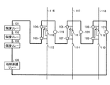
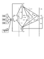
以下では、第1の実施形態における計測タイミングの決定方法を詳細に説明する。図1に例示する送電線保護システムは、保護リレー101〜103、計測装置104〜109、遮断器110〜112、開閉器113〜115、送電線116〜118、母線保護リレー130を含む。
Below, the determination method of the measurement timing in 1st Embodiment is demonstrated in detail. The power transmission line protection system illustrated in FIG. 1 includes
保護リレー101〜103、計測装置104〜109、ならびに、母線保護リレー130は、例えばイーサネット(登録商標)などのディジタルネットワークに接続される。図1における保護リレー101〜103、計測装置104〜109、遮断器コントローラ119〜121、ならびに、母線保護リレー130は、リング型のネットワークを構成する。リング型のネットワークは、例えば国際標準規格IEC62439−3(International Electrotechnical Commission 62439-3)が規定するHighly Availablity Seamless Ringでもよいし、IEEE 802.5(Institute of Electrical and Electronics Engineers 802.5)、IEEE802.4、FDDI(Fiber Distributed Data Interface)といったMAC(Media Access Control)方式に対応したネットワークでもよい。
The
計測装置104〜109は、それぞれ対応する送電線116〜118に関する物理量を計測する。この例では、計測装置104および105が送電線116に関する物理量を計測し、計測装置106および107が送電線117に関する物理量を計測する。また、計測装置108および109が送電線118に関する物理量を計測する。
The
計測装置104〜109に計測される物理量は、例えば送電線116〜118により送電される電流の電流値および電圧値である。当該電流の交流周波数を物理量としてさらに計測してもよい。これに限らず、計測装置104〜109は、計測ポイントにおける温度、湿度、圧力、風力量、水流量といった情報を物理量としてさらに測定してもよい。
The physical quantities measured by the
典型的な変電所では、通常、1つの計測装置が故障しても保護リレーが同じ位置の物理量を取得できるよう、それぞれ2箇所の物理量を計測する計測装置を2台設置し、物理量の計測手段を冗長化する。例えば、図1の例では、計測装置104、106および108が、それぞれ計測装置105、107および109と略同じ位置の物理量を計測する。なお、本第1の実施形態の実施に当たっては、このように計測装置を冗長化しなくてもよい。
In a typical substation, usually two measuring devices that measure physical quantities at two locations are installed so that the protection relay can acquire physical quantities at the same position even if one measuring device fails. Make it redundant. For example, in the example of FIG. 1, the
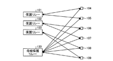
計測装置104〜109は、図2に示す関係に従い、保護リレー101〜103、ならびに、母線保護リレー130から、時刻を示す時刻情報を含むメッセージ(以下では、Syncメッセージと呼ぶ)をネットワークを介して受信する。保護リレー101〜103、ならびに、母線保護リレー130は、Syncメッセージを送信する時刻を示す時刻情報を、当該Syncメッセージに対して記述する。
In accordance with the relationship shown in FIG. 2, the measuring
例えば、計測装置104〜109は、保護リレー101〜103のうち対応する保護リレーから送信されたSyncメッセージを受信する。各計測装置104〜109は、さらに、母線保護リレー130から送信されたSyncメッセージを受信する。すなわち、計測装置104〜109は、複数の送信元からSyncメッセージを受信できる。また、保護リレー101〜103、ならびに、母線保護リレー130は、それぞれ複数の送信先に対してSyncメッセージを送信できる。
For example, the measuring
そして、計測装置104〜109は、Syncメッセージに含まれる時刻情報を利用して計測タイミングを調整して物理量を計測し、図2に示す関係に従って保護リレー101〜103および母線保護リレー130に対して物理量の値を含むメッセージ(以下では、物理量データフレームと呼ぶ)を送信する。
Then, the measuring
ここで、計測装置104〜109は、物理量を計測する計測タイミングを、送信先の保護リレーの時刻に換算したときに当該計測タイミングが等間隔になるように調整する。なお、計測装置104〜109は、異なる保護リレー(例えば保護リレー101と母線保護リレー130)に対して送信する物理量の計測タイミングの間隔が予め決められた時間内であった場合、計測を一度で済ませてもよい。
Here, the
計測装置104および105は、保護リレー101に対して、計測装置106および107は保護リレー102に対して、計測装置108および109は保護リレー103に対して、それぞれ物理量データフレームを送信する。また、計測装置104〜109は、それぞれ母線保護リレー103に対して物理量データフレームを送信する。計測装置104〜109は、物理量データフレームをユニキャストで送信してもよいし、マルチキャストで送信してもよい。
The
保護リレー101〜103は、計測装置104〜109から受信した物理量データフレームに含まれる物理量を解析し、送電線における異常を検知する。異常を検知した場合、保護リレー101〜103は、ネットワークを介してそれぞれ遮断器コントローラ119〜121に遮断指令を送信する。また、典型的な変電所に本第1の実施形態を適用する場合、保護リレー101〜103、ならびに、母線保護リレー130は、自身の時刻が記されたSyncメッセージをマルチキャストで定期的に送信する。この例に限らず、保護リレー101〜103、ならびに、母線保護リレー130は、ユニキャストを用いてSyncメッセージを計測装置104〜109に対し、図2に示す関係に従い定期的に送信してもよい。
The protection relays 101 to 103 analyze a physical quantity included in the physical quantity data frame received from the measuring
なお、保護リレー101〜103、計測装置104〜109、ならびに、母線保護リレー130の対応関係は、図2に示す関係に限られるものではなく、他の組み合わせであってもよい。特に、各計測装置104〜109が物理量データフレームを送信する送信先の保護リレー数は、異なっていてもよい。この場合であっても、本第1の実施形態においては、各計測装置104〜109は、少なくとも、物理量データフレームの送信先である装置からSyncメッセージを受信する。
Note that the correspondence relationship between the protection relays 101 to 103, the measuring
遮断器コントローラ119〜121は、それぞれ対応する保護リレー101〜103から遮断指令を受信すると、それぞれ対応する遮断器110〜112に対して遮断信号を送る。遮断器コントローラ119〜121と遮断器110〜112との間は、それぞれアナログの制御ケーブルで接続される。遮断器110〜112は、それぞれ送電線116、117および118を遮断する機能を備える。開閉器113〜115は、保守などのために必要に応じて送電線116〜118をそれぞれ開閉する機能を備える。
When the
図1における計測装置104〜109が保護リレー101〜103および母線保護リレー130の時刻を取得する方法は、特に限定されない。例えば、保護リレー101〜103、計測装置104〜109、ならびに、母線保護リレー130は、IEEE1588またはNTP(Network Time Protocol)に準拠した機能を備えてもよい。第1の実施形態では、保護リレー101〜103、計測装置104〜109、ならびに、母線保護リレー130がIEEE1588の1step方式およびPeer delay mechanismと呼ばれる方式に準拠する場合の例を説明する。
The method by which the measuring
すなわち、保護リレー101〜103、計測装置104〜109、ならびに、母線保護リレー130がSyncメッセージを送信または転送する際に、推定される転送処理時間を示す情報をSyncメッセージに含める。また、保護リレー101〜103、計測装置104〜109、ならびに、母線保護リレー130は、隣接する機器へPdelay_Reqメッセージを送信する機能、および隣接機器からPdelay_Reqメッセージを受信し、Pdelay_Responseメッセージを返送する機能、およびPdelay_Responseメッセージを受信し、隣接機器との間のケーブル中の伝送遅延時間を計算する機能を備える。
That is, when the protection relays 101 to 103, the measuring
Pdelay_Reqメッセージは、Pdelay_Reqメッセージ送信時の時刻を示す情報が含まれる。また、Pdelay_Responseメッセージには、Pdelay_Reqメッセージ受信時の時刻およびPdelay_Responseメッセージ送信時の時刻を示す情報が含まれる。 The Pdelay_Req message includes information indicating the time when the Pdelay_Req message is transmitted. The Pdelay_Response message includes information indicating the time when the Pdelay_Req message is received and the time when the Pdelay_Response message is transmitted.
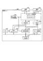
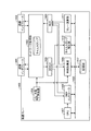
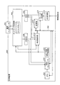
図3において、計測装置500は、図1における計測装置104〜109に該当する。本第1の実施形態に係る計測装置500は、通信インタフェース501および502、ネットワーク処理部503、MUX(マルチプレクサ)505、DEMUX(デマルチプレクサ)506、CPU(Central Processing Unit)512、時刻計算部513、記憶部514、DMA(Direct Memory Access)コントローラ516、水晶発振器515、タイミング調整部517、フレーム生成部518、ならびに、A/D変換部519を備える。
In FIG. 3, a measuring
CPU512は、例えば汎用のプロセッサであり、記憶部514に記憶されたプログラムに従い、図示されないRAM(Random Access Memory)をワークメモリとして、この計測装置500の全体の動作を制御する。バス530は、CPU512、時刻計算部513、記憶部514、DMAコントローラ516、タイミング調整部517およびフレーム生成部518を、互いに通信可能にするために接続する。
The
水晶発振器515は、水晶を利用した、所定の周波数で発振する発振器と、当該発振器で発生した発振信号の発振数をカウントするクロックカウンタを含む。水晶発振器515から出力されるクロックカウンタの値から求めた時刻は、当該計測装置500における時刻を示す時刻情報に相当する。クロックカウンタは、ネットワーク処理部503、時刻計算部513およびタイミング調整部517に供給される。
The
通信インタフェース501および502は、例えばイーサネット(登録商標)、無線LAN(Local Area Network)といった通信方式に対応したインタフェースである。ネットワーク処理部503は、通信方式に対応したMAC(Media Access Control)処理を行い、入力されたフレームを適切な出力先のモジュールへ出力する。ネットワーク処理部503は、フレームの宛先およびフレームの入力元のモジュールに応じて、出力先のモジュールを選択する。より具体的には、ネットワーク処理部503は、MUX505から入力されたフレームを通信インタフェース501および502のうち少なくとも一方に出力する。
The communication interfaces 501 and 502 are interfaces corresponding to communication methods such as Ethernet (registered trademark) and wireless LAN (Local Area Network). The
また、ネットワーク処理部503は、通信インタフェース501または502から入力された、宛先アドレスが計測装置500であるフレームをDEMUX506に対して出力する。ネットワーク処理部503は、通信インタフェース501から入力された、宛先アドレスがユニキャストアドレスであり且つ宛先アドレスが計測装置500ではないフレームを、通信インタフェース502へ出力する。同様に、ネットワーク処理部503は、通信インタフェース502から入力された、宛先アドレスがユニキャストアドレスであり且つ宛先アドレスが計測装置500ではないフレームを通信インタフェース501へ出力する。
Further, the
さらに、ネットワーク処理部503は、通信インタフェース501から入力された、宛先アドレスがマルチキャストアドレスであるフレームを、通信インタフェース502およびDEMUX506に対して出力する。同様に、ネットワーク処理部503は、通信インタフェース502から入力された、宛先アドレスがマルチキャストアドレスであるフレームを、通信インタフェース501およびDEMUX506に対して出力する。
Further, the
なお、ネットワーク処理部503は、通信インタフェース501または502から入力されたフレームのうち、一度受信した同一のフレームを破棄することができる。
The
ネットワーク処理部503は、通信インタフェース501または502におけるフレームの入出力時に、水晶発振器515のクロックカウンタを、当該入出力時の時刻を示すタイムスタンプとして保持する。MUX505は、複数のモジュールの何れかからフレームを取得し、転送する。DEMUX506は、Syncメッセージを時刻計算部513へ出力すると共に、少なくともSyncメッセージ以外のフレームをDMAコントローラ516に転送する。
The
これに限らず、DEMUX506は、Syncメッセージを時刻計算部513およびDMAコントローラ516へ出力してもよい。また、DEMUX506は、Pdelay_ReqメッセージおよびPdelay_Responseメッセージを、時刻計算部513およびDMAコントローラ516の少なくとも一方に出力してもよい。
However, the
時刻計算部513は、入力されたSyncメッセージに含まれる、Syncメッセージを送信した時刻を示す時刻情報を利用して、Syncメッセージの送信元である保護リレーのクロックによる時刻を計算する。また、時刻計算部513は、記憶部514に、保護リレーの時刻を水晶発振器515のクロックカウンタの値に変換するためのパラメータ(以下では、変換パラメータと呼ぶ)を保存する。
The
記憶部514は、例えば不揮発性の半導体メモリやハードディスクドライブなどからなり、CPU512が動作するためのプログラムが記憶される。記憶部514は、さらに、当該計測装置500の通信先の保護リレーのアドレスと、上述の変換パラメータと、物理量の計測頻度と、計測開始時のクロックカウンタの値とで構成されるレコードを、少なくとも1つ以上含むテーブルを保持する。
The
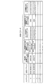
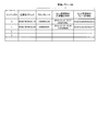
図4に例示するデータは、保護リレーまたは母線保護リレー毎のレコードからなるテーブルとして記憶部514に保存される。各レコードは、インデックスで識別される。保護リレーのアドレスは、当該計測装置500が保護リレーにアクセスする際に用いるアドレスであって、例えばイーサネット(登録商標)のMACアドレスを用いることができる。これに限らず、保護リレーのアドレスとして、保護リレーのIP(Internet Protocol)アドレスを用いてもよい。
The data illustrated in FIG. 4 is stored in the
変換パラメータは、例えば、保護リレーの時刻で換算した水晶発振器515の周波数(換算周波数と呼ぶ)、Syncメッセージ受信時における保護リレーの推定時刻、ならびに、Syncメッセージ受信時における水晶発振器515のクロックカウンタの値である。換算周波数は、例えば、2のSyncメッセージに含まれる時刻情報の差分と、当該2のSyncメッセージを通信インタフェース501または502で受信した際にネットワーク処理部503に保持されたタイムスタンプの差分との比に基づき算出することができる。
The conversion parameters include, for example, the frequency of the
なお、換算周波数は、保護リレーにおける時刻の進行速度と、計測装置500における時刻の進行速度との違いを表す。換言すれば、換算周波数と水晶発振器515に規定の発振周波数とを比較することで、保護リレーにおいて時刻を計測するクロックにより規定される1秒と、計測装置500における水晶発振器515から出力されるクロックカウンタにより規定される1秒との違いを知ることができる。
The converted frequency represents the difference between the time advance speed of the protection relay and the time advance speed of the measuring
図4の例では、変換パラメータとして、さらに物理量の計測頻度と計測開始時のクロックカウンタとが含められている。物理量の計測頻度は、例えば保護リレーの時刻で換算した1秒当たりに、当該計測装置500が物理量を計測する回数である。計測開始時のクロックカウンタは、予め設定されるかまたは保護リレーから通知された、保護リレーの時刻を水晶発振器515のクロックカウンタに変換した値である。計測装置500は、クロックカウンタの値がこの計測開始時のクロックカウンタで指定された値になると、計測動作を開始する。
In the example of FIG. 4, a physical quantity measurement frequency and a clock counter at the start of measurement are further included as conversion parameters. The physical quantity measurement frequency is, for example, the number of times the
DMAコントローラ516は、CPU512が生成したフレームをMUX505に対して出力すると共に、DEMUX506から入力されたフレームを記憶部514に記憶させる。タイミング調整部517は、当該計測装置500における物理量の計測タイミングを決定する。また、タイミング調整部517は、内部に次の物理量の計測タイミングまでのクロック数を保持するカウンタを備える。
The
A/D変換部519は、外部の装置で計測された物理量のアナログ信号(物理量信号)を、ディジタルデータによる物理量に変換する。このA/D変換部519は、本第1の実施形態における計測部に該当する。フレーム生成部518は、タイミング調整部517から計測タイミングを示す信号を受けたときに、A/D変換部519からディジタル化された物理量を取得し、この物理量の値を含む物理量データフレームを生成する。生成された物理量データフレームは、MUX505に対して出力される。
The A /
図5に示される保護リレー1400’は、図1で示した保護リレー101〜103、ならびに、母線保護リレー130に相当する。保護リレー1400’は、通信インタフェース1401および1402、ネットワーク処理部1403、水晶発振器1404、DEMUX1405、MUX1406、CPU1407、DMAコントローラ1408、時刻提供部2209、リレー演算部1411、ならびに、記憶部1412を備える。
A
CPU1407は、例えば汎用のプロセッサであり、記憶部1412に記憶されたプログラムに従い、同じく図示されないRAMをワークメモリとして、この保護リレー1400’の全体の動作を制御する。バス1430は、CPU1407、時刻提供部2209、記憶部1412、DMAコントローラ1408およびリレー演算部1411を、互いに通信可能に接続する。
The
なお、通信インタフェース1401および1402、ネットワーク処理部1403、水晶発振器1404およびDMAコントローラ1408は、図3を用いて説明した計測装置500における通信インターフェイス501および502、ネットワーク処理部503、水晶発振器515およびDMAコントローラ516それぞれのモジュールと同等であるので、ここでの詳細な説明を省略する。
Note that the
保護リレー1400’において、DEMUX1405は、通信インターフェイス1401または1402で受信したPdeley_ResponseメッセージおよびPdeley_Reqメッセージを時刻提供部2209に転送する。また、DEMUX1405は、通信インターフェイス1401または1402で受信した物理量データフレームを、DMAコントローラ1408に転送する。DMAコントローラ1408は、DEMUX1405から転送された物理量データフレームをCPU1407およびリレー演算部1411に転送する。
In the
MUX1406は、DMAコントローラ1408、時刻提供部2209およびリレー演算部1411からフレームを取得し、ネットワーク処理部1403に転送する。
The
時刻提供部2209は、水晶発振器1404から出力されるクロックカウンタに基づき、定期的にSyncメッセージを生成する。生成されたSyncメッセージは、MUX1406を介してネットワーク処理部1403に転送され、通信インタフェース1401または1402により送信される。
The
また、時刻提供部2209は、Pdeley_ReqメッセージおよびPdeley_Responseメッセージを生成する。生成されたPdeley_ReqメッセージおよびPdeley_Responseメッセージは、MUX1406を介してネットワーク処理部1403に転送され、通信インタフェース1401または1402により送信される。さらに、時刻提供部2209は、通信インタフェース1401または1402により受信され、ネットワーク処理部1403およびDEMUX1405を介して転送されたPdeley_ReqメッセージおよびPdeley_Responseメッセージを処理する。
In addition, the
記憶部1412は、例えばハードディスクドライブや不揮発性の半導体メモリからなり、CPU1407が動作するためのプログラムが記憶される。記憶部1412は、さらに、送信先の計測装置それぞれに対する計測装置のアドレスを保持すると共に、通信インタフェース1401または1402で、複数の計測装置からそれぞれ受信した物理量データフレームに含まれる物理量の値を保持する。リレー演算部1411は、記憶部1412に保持した複数の物理量情報を用いて、送電線における異常を検証する。
The
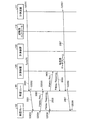
次に、本第1の実施形態に係る計測装置の処理を説明する。図6は、計測装置104が保護リレー101に物理量の値を記述した物理量データフレームを送信する際の一例の処理を示す。図1の例では、計測装置104から出力された物理量データフレームは、計測装置105を介して保護リレー101に受信されることになる。
Next, processing of the measuring apparatus according to the first embodiment will be described. FIG. 6 shows an example of processing when the measuring
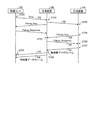
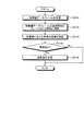
図6に示すシーケンスは、第1、第2および第3の、3のシーケンスに分類される。第1のシーケンスは、保護リレー101が定期的に送信したSyncメッセージを計測装置104が受信し、計測装置104は、受信したSyncメッセージに基づき保護リレー101の時刻を把握する。第2のシーケンスは、計測装置105および計測装置104が隣接する機器との間のケーブル中における通信遅延を定期的に測定する。第3のシーケンスは、計測装置104が保護リレー101に対し、物理量データフレームを定期的に送信する。
The sequence shown in FIG. 6 is classified into first, second, and third sequences. In the first sequence, the
なお、これら第1〜第3のシーケンスは、それぞれ独立したタイミングで実行されてもよく、第1〜第3のシーケンスがどのような順番で行われてもよい。また、本第1の実施形態では、第2のシーケンスの実行を省略することができる。第2のシーケンスは、Syncメッセージの通信遅延を高精度に計測するために実行される。高精度に通信遅延を計測することで、計測装置は、保護リレー側の時刻を高精度に把握することができる。高精度が必要ない場合、計測装置は、第2のシーケンスの実行を省略可能である。 Note that these first to third sequences may be executed at independent timings, and the first to third sequences may be executed in any order. In the first embodiment, the execution of the second sequence can be omitted. The second sequence is executed in order to measure the communication delay of the Sync message with high accuracy. By measuring the communication delay with high accuracy, the measuring device can grasp the time on the protection relay side with high accuracy. When high accuracy is not required, the measurement apparatus can omit the execution of the second sequence.
先ず、第1のシーケンスについて説明する。保護リレー101は、Syncメッセージ701をネットワークに対して送信する(ステップS751)。このSyncメッセージ701の宛先アドレスは、計測装置104のアドレス若しくはマルチキャストアドレスである。このSyncメッセージ701は、ステップS752で計測装置105に受信される。
First, the first sequence will be described. The
計測装置105は、ステップS752で受信したSyncメッセージ701を、計測装置104に転送する。ステップS752におけるSyncメッセージ701の転送処理を、図3を参照しながら説明する。計測装置105(計測装置500)において、通信インタフェース501がSyncメッセージ701を受信したと想定する。通信インタフェース501は、受信したSyncメッセージ701をネットワーク処理部503に対して出力する。ネットワーク処理部503は、水晶発振器515から出力されたクロックカウンタの値を、タイムスタンプとして取得する。
The measuring
Syncメッセージ701の宛先アドレスは、計測装置104のアドレス若しくはマルチキャストアドレスであるため、ネットワーク処理部503は、Syncメッセージ701を通信インタフェース502へ出力する。Syncメッセージ701の宛先アドレスがマルチキャストアドレスの場合、ネットワーク処理部503は、さらにDEMUX506に対してSyncメッセージ701を出力する。通信インタフェース502は、ネットワーク処理部503から受け取ったSyncメッセージ701を、ネットワークに対して出力する。
Since the destination address of the
なお、ネットワーク処理部503は、Syncメッセージ701の推定される転送処理時間D_transと、Syncメッセージ701のCorrectionフィールドに記載された値D_old_correctionと、計測装置105と保護リレー101との間の通信遅延D_pdelayとを用いて、下記の式(1)に従い値D_new_correctionを計算し、結果をSyncメッセージ701のCorrectionフィールドに含めてもよい。なお、転送処理時間D_transは、予め決められた値を用いてもよい。
D_new_correction=D_trans+D_old_correction+D_pdelay …(1)
The
D_new_correction = D_trans + D_old_correction + D_pdelay (1)
また、ネットワーク処理部503は、通信インタフェース502にフレームを出力する直前且つ転送処理時間を計算する際に、水晶発振器515のクロックカウンタC_transを取得し、通信インタフェース501からフレームが入力されたときのタイムスタンプC_inと、予め決められたCorrectionフィールドの処理時間D_proc_correction、予め決められた水晶発振器515の周波数fを用いて、下記の式(2)を用いて転送処理時間D_transを計算してもよい。
D_trans=f×(C_trans−C_in+D_proc_correction) …(2)
Further, the
D_trans = f × (C_trans−C_in + D_proc_correction) (2)
以上がステップS752における計測装置105の処理である。
The above is the process of the measuring
計測装置104は、ステップS753でSyncメッセージ701を受信する。ステップS753におけるSyncメッセージ701の受信処理を、図3を参照しながら説明する。計測装置104(計測装置500)において、通信インタフェース501がSyncメッセージ701を受信したと想定する。通信インタフェース501は、Syncメッセージ701をネットワーク処理部503に対して出力する。ネットワーク処理部503は、水晶発振器515から出力されるクロックカウンタを、タイムスタンプとして取得する。
The measuring
Syncメッセージ701の宛先アドレスは、計測装置104のアドレス若しくはマルチキャストアドレスであるため、ネットワーク処理部503は、Syncメッセージ701をDEMUX506に対して出力する。Syncメッセージ701の宛先アドレスがマルチキャストアドレスの場合、ネットワーク処理部503は、さらに通信インタフェース502に対してSyncメッセージ701を出力する。その後の処理は、上述したステップS752における処理と同様である。
Since the destination address of the
次に、DEMUX506は、Syncメッセージ701の出力先を決定する。DEMUX506は、入力されたフレームがSyncメッセージ701である場合に、当該フレームを時刻計算部513に出力し、それ以外のフレームを全てDMAコントローラ516へ出力する。この場合は、入力されたフレームがSyncメッセージ701であるため、DEMUX506は、当該Syncメッセージ701を時刻計算部513に対して出力する。
Next, the
時刻計算部513は、ネットワーク処理部503から、Syncメッセージ701受信時のクロックカウンタを取得する。そして、時刻計算部513は、水晶発振器515の発振周波数を保護リレー101のクロックで換算した換算周波数を計算する。より具体的には、時刻計算部513は、Syncメッセージ701に記述されるSyncメッセージ701の送信時刻T_sync_send、記憶部514に保存していた前回受信したSyncメッセージの送信時刻、Syncメッセージ701受信時にネットワーク処理部503にタイムスタンプとして保持されたクロックカウンタ、ならびに、前回のSyncメッセージ受信時にタイムスタンプとして保持したクロックカウンタを用い、さらにSyncメッセージ701の通信遅延D_syncを用いて換算周波数を計算する。
The
なお、Syncメッセージ701の通信遅延D_syncは、予め決められた値でもよい。これに限らず、Syncメッセージ701の通信遅延D_syncは、Syncメッセージ701のCorrectionフィールドに記された値でもよい。さらに、Syncメッセージ701の通信遅延D_syncは、Syncメッセージ701のCorrectionフィールドに記された値に、第2のシーケンスで計測した計測装置105と計測装置104との間の通信遅延を加えた値でもよい。
Note that the communication delay D_sync of the
時刻計算部513は、保護リレー101のクロックで換算した換算周波数を、例えばPI(Proportional-Integral)制御、回帰解析、線形計画法などの方法で計算することができる。なお、時刻計算部513は、換算周波数を計算するために、今回および前回のSyncメッセージ受信時のSyncメッセージの受信時刻およびクロックカウンタだけでなく、それ以前に受信した1以上のSyncメッセージの受信時刻およびクロックカウンタの値を記憶部514に保存し、利用してもよい。これにより回帰解析、線形計画法などの方法を用いる場合に、換算周波数を精度良く推測できる。
The
時刻計算部513は、水晶発振器515の発振周波数を保護リレー101のクロックで換算した換算周波数を、記憶部514に保存する。
The
また、時刻計算部513は、下記の式(3)を用いてSyncメッセージ701受信時の保護リレー101の時刻T_sync_est_recvを計算し、記憶部514に保存する。
T_sync_est_recv=T_sync_send+D_sync …(3)
In addition, the
T_sync_est_recv = T_sync_send + D_sync (3)
さらに、時刻計算部513は、Syncメッセージ701受信時のクロックカウンタを、記憶部514に保存する。以上が、ステップS753における計測装置104の処理である。
Further, the
次に、第2のシーケンスについて説明する。第2のシーケンスでは、隣接機器間の遅延を測定する。計測装置105および計測装置104は、定期的にPdelay_Reqメッセージを隣接する機器に送信し、隣接する機器から送信されたPdelay_Responseメッセージを受信する。図6では、計測装置104が計測装置105との間の通信遅延を計測し、計測装置105が保護リレー101との間の通信遅延を計測する様子が示されている。何れも処理方法は同じであるため、ここでは、計測装置104と計測装置105との間の通信遅延を計測する方法について説明する。
Next, the second sequence will be described. In the second sequence, a delay between adjacent devices is measured. The
計測装置104は、ステップS754でPdelay_Reqメッセージ705を送信する。このステップS754における処理を、図3を参照しながら説明する。計測装置104(計測装置500)の時刻計算部513は、Pdelay_Reqメッセージ705を生成する。MUX505は、時刻計算部513からPdelay_Reqメッセージ705を取得し、ネットワーク処理部503に対して出力する。ネットワーク処理部503は、Pdelay_Reqメッセージ705の推定される送信時刻を、水晶発振器515のクロックカウンタの値を用いて計算し、当該送信時刻を示す推定送信時刻情報をPdelay_Reqメッセージ705に記述する。
The measuring
ネットワーク処理部503は、通信インタフェース501および通信インタフェース502のうち少なくとも一方に対してPdelay_Reqメッセージ705を出力する。通信インタフェース501および/または通信インタフェース502は、Pdelay_Reqメッセージ705をネットワークに対して出力する。以上がステップS754における計測装置104の処理である。
The
計測装置105は、ステップS755で、Pdelay_Reqメッセージ705を受信する。ステップS755における計測装置105の処理を、図3を参照しながら説明する。なお、計測装置105は、通信インタフェース502でPdelay_Reqメッセージ705を受信したと想定する。通信インタフェース502は、受信したPdelay_Reqメッセージ705を、ネットワーク処理部503に対して出力する。
The measuring
次に、ネットワーク処理部503は、Pdelay_Reqメッセージ705が入力されたときのクロックカウンタを、水晶発振器515から取得する。ネットワーク処理部503は、DEMUX506に対してPdelay_Reqメッセージ705を出力する。DEMUX506は、このPdelay_Reqメッセージ705を、時刻計算部513に対して出力する。時刻計算部513は、Pdelay_Reqメッセージ705に応じて、Pdelay_Responseメッセージ706を生成する。そして、時刻計算部513は、Pdelay_Reqメッセージ705受信時のクロックカウンタをネットワーク処理部503から取得する。
Next, the
次に、時刻計算部513は、Pdelay_Responseメッセージ706に対し、Pdelay_Reqメッセージ705に記述された、Pdelay_Reqメッセージ705の送信時刻およびPdelay_Reqメッセージ705の受信時刻を記述する。時刻計算部513は、Pdelay_Responseメッセージ706をMUX505に対して出力する。
Next, the
MUX505は、時刻計算部513から出力されたPdelay_Responseメッセージ706を取得し、ネットワーク処理部503に対して出力する。ネットワーク処理部503は、Pdelay_Responseメッセージ706の推定される送信時刻を、Pdelay_Responseメッセージ706に対して記述する。ネットワーク処理部503は、通信インタフェース502に対してPdelay_Responseメッセージ706を出力する。通信インタフェース502は、Pdelay_Responseメッセージ706を送信する。以上が、ステップS755における処理である。
The
計測装置104は、ステップS756で、Pdelay_Responseメッセージ706を受信する。ステップS756における計測装置104の処理を、図3を参照しながら説明する。なお、計測装置104は、Pdelay_Responseメッセージ706を通信インタフェース501で受信したものと想定する。通信インタフェース501は、受信したPdelay_Responseメッセージ706を、ネットワーク処理部503に対して出力する。ネットワーク処理部503は、Pdelay_Responseメッセージ706が入力されたときの水晶発振器515のクロックカウンタを取得する。そして、ネットワーク処理部503はDEMUX506に対してPdelay_Responseメッセージ706を出力する。
In step S756, the
DEMUX506は、時刻計算部513に対してPdelay_Responseメッセージ706を出力する。時刻計算部513は、Pdelay_Reqメッセージ705の送信時刻Pd_req_sendと、Pdelay_Reqメッセージ705の受信時刻Pd_req_recvと、Pdelay_Responseメッセージ706の送信時刻Pd_resp_sendと、Pdelay_Responseメッセージ706の受信時刻Pd_resp_recvとを用いて、通信遅延Pd_delayを、例えば下記の式(4)を用いて計算する。
Pd_delay={(Pd_req_recv−Pd_req_send)+(Pd_resp_recv−Pd_resp_send)}/2 …(4)
The
Pd_delay = {(Pd_req_recv−Pd_req_send) + (Pd_resp_recv−Pd_resp_send)} / 2 (4)
時刻計算部513は、ステップS753において換算周波数を計算するとき、計測装置104と計測装置105との間の通信遅延D_pdelayとして、通信遅延Pd_delayを使用してよい。これに限らず、時刻計算部513は、過去に計算した1以上のPd_delayの値を用いて通信遅延Pd_delay、ならびに、計測装置104と計測装置105との間の通信遅延D_pdelayを求めてもよい。例えば、過去に計算した1以上の通信遅延Pd_delayの平均値を利用する方法がある。以上が、ステップS756における処理である。
When calculating the converted frequency in step S753, the
次に、第3のシーケンスについて説明する。第3のシーケンスでは、計測装置104が物理量の値を保護リレー101へ送信する。先ず、計測装置104は、ステップS757で、物理量データフレーム707をネットワークに対して送信する。
Next, the third sequence will be described. In the third sequence, the
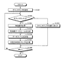
ステップS757における計測装置104(計測装置500)の処理を、図3および図7を用いて説明する。タイミング調整部517は、内部に物理量の計測タイミングまでのクロック数を保持するダウンカウンタを備える(図示しない)。また、タイミング調整部517は、次に計測する物理量の送信先である装置(保護リレー)のレコードを指し示すインデックスを保持する。
The processing of the measurement device 104 (measurement device 500) in step S757 will be described with reference to FIGS. The
図7に示すステップS1201において、タイミング調整部517は、記憶部514に保存されたテーブルにおける、計測開始時のクロックカウンタの値から、現在の水晶発振器515のクロックカウンタの値を減じた値を、ダウンカウンタに設定する(ステップS1201)。
In step S1201 shown in FIG. 7, the
タイミング調整部517は、ステップS1202で、水晶発振器515からクロックカウンタ信号を受信すると、ダウンカウンタの値が「0」であるか否かを判定する。判定の結果、若し、値が「0」より大きければ、処理をステップS1203に移行させてダウンカウンタの値を1だけ減じる。そして、当該計測装置104の動作が停止されていなければ(ステップS1208)、処理をステップS1202に戻す。
When the
なお、計測装置104の動作の停止は、例えば作業員が当該計測装置104の動作を停止するなどの操作を表す。なお、この図7では、ステップS1208において計測装置104の動作が停止されているか否かを判定するように示されているが、動作停止の方法が電源OFFの場合、ここでの判定処理は行われない。
Note that the stop of the operation of the measuring
一方、タイミング調整部517は、ステップS1202でダウンカウンタの値が「0」であると判定した場合、図7に示すステップS1204を実行する。ステップS1204において、タイミング調整部517は、フレーム生成部518に対してインデックスを出力する。フレーム生成部518は、タイミング制御部517からインデックスを入力されると、A/D変換部519からディジタル化された物理量を取得する。次に、フレーム生成部518は、物理量の値を記述した物理量データフレーム707を生成する(ステップS1205)。なお、フレーム生成部518は物理量データフレーム707の宛先アドレスを、インデックスが指し示すレコードが保持する保護リレーのアドレスに設定してもよい。MUX505は、フレーム生成部518から物理量データフレーム707を取得し、ネットワーク処理部503に対して出力する。
On the other hand, if the
なお、フレーム生成部518は、物理量データフレーム707に物理量の計測タイミングを示す情報を記述することができる。この計測タイミングを示す情報は、例えばネットワークに送信されるメッセージの順番を示すシーケンスナンバであってよい。クロックカウンタに基づく時刻情報(タイムスタンプ)を、当該計測タイミングを示す情報として用いることも可能である。計測タイミングを示す情報を物理量データフレーム707に記述することで、複数の計測装置から物理データフレームを受信した保護リレーは、それぞれの物理データフレームに記載された物理量が計測されたタイミングの関係を把握できるため、計測装置は同一時刻における複数地点の物理量を比較できる。
Note that the
次のステップS1206で、ネットワーク処理部503は、通信インタフェース501および通信インタフェース502のうち少なくとも一方に対して、物理量データフレーム707を出力する。通信インタフェース501および/または通信インタフェース502は、この物理量データフレーム707を、ネットワークに対して送信する。
In next step S1206, the
タイミング調整部517は、インデックスをフレーム生成部518に対して出力した後、次回物理量を計測するタイミングを決定する(ステップS1207)。ステップS1207において、タイミング調整部517は、記憶部514に記憶されたそれぞれの保護リレーのレコードについて、対象となる保護リレー(例えば保護リレー101)のクロックで換算した水晶発振器515の周波数である換算周波数F_oscillatorと、1秒間当たりの計測回数を示す計測頻度F_samplingとを用いて、下記の式(5)〜(7)により以下の値I_sampling、値N_correctionおよび値I_correctionを計算する。なお、関数Floor(x)は、値xを越えない最大の整数を返す関数とする。
I_sampling=Floor(F_oscillator/F_sampling) …(5)
N_correction=F_oscillator−I_sampling×F_sampling …(6)
I_correction=Floor(N_correction/I_sampling) …(7)
After outputting the index to the
I_sampling = Floor (F_oscillator / F_sampling) (5)
N_correction = F_oscillator−I_sampling × F_sampling (6)
I_correction = Floor (N_correction / I_sampling) (7)
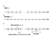
値I_samplingは、計測タイミングの間隔を水晶発振器515のクロック数で表した値である。ただし、値I_samplingは、クロック単位の値であって、関数Floor()で少数点以下を切り落とされた値である。そのため、水晶発振器515が値I_samplingの間隔で値F_samplingの回数計測する時間は、若干1秒に満たない可能性がある。そこで、タイミング調整部517は、所定の割合で計測タイミングの間隔を1クロック分補正する。値N_correctionは、1秒当たりの補正回数を表す。値I_correctionは、何回計測する毎に補正するかを表す。
The value I_sampling is a value representing the measurement timing interval by the number of clocks of the
図8に値I_samplingおよび値I_correctionの関係を示す。基本的に、計測タイミングの間隔は値I_correctionである。しかし、値I_correctionで示す回数計測する毎に、計測タイミングの間隔は値I_sampling+1に補正される。
FIG. 8 shows the relationship between the value I_sampling and the value I_correction. Basically, the measurement timing interval is the value I_correction. However, every time the number of times indicated by the value I_correction is measured, the measurement timing interval is corrected to the
タイミング調整部517は、送信先の装置(例えば保護リレー101および130)のそれぞれについて、次回の計測タイミングまでのクロック数C_next_samplingを、値N_correctionおよび値I_correctionを用いて計算する。そして、タイミング調整部517は、各送信先の装置に対するクロック数C_next_samplingのうち最も値が小さいクロック数C_next_sampling_minを求め、下記の式(8)を用いて、次回の計測タイミングまでのクロック数C_samplingを決定する。
C_sampling=C_next_sampling_min−(T_current−T_prev_sampling) …(8)
The
C_sampling = C_next_sampling_min− (T_current−T_prev_sampling) (8)
なお、式(8)において、値T_currentは、現在の水晶発振器515のクロックカウンタである。また、値T_prev_samplingは、タイミング調整部517がフレーム生成部518へインデックスを出力した時点での水晶発振器515のクロックカウンタである。つまり、値(T_current−T_prev_sampling)は、タイミング調整部517が演算に要する時間を表す。
In equation (8), the value T_current is the current clock counter of the
値C_samplingが予め決められた時間よりも短い場合、タイミング調整部517は次の計測タイミングと今回の計測タイミングを統合してもよい。
When the value C_sampling is shorter than a predetermined time, the
図9を用いてタイミング調整部517が計測タイミングを統合してもよい場合を説明する。図9(a)および図9(b)は、例えば、それぞれ保護リレー101および母線保護リレー130に対して送信する物理量を計測する計測タイミングを示すものとする。保護リレー101および母線保護リレー130それぞれに搭載される水晶発振器1404や、計測装置104に搭載される水晶発振器515の発振周波数は、周辺温度などの変化により、誤差を含む可能性がある。また、保護リレー101および母線保護リレー130が要求する物理量の計測間隔が異なる可能性がある。
The case where the
この例では、図9(a)に例示する保護リレー101に対する計測タイミングの方が、図9(b)に例示する母線保護リレー130に対する計測タイミングよりも間隔が長くなっている。また、図9(a)および図9(b)において、各計測タイミングの間隔は補正される場合があるので、必ずしも一定になっていない。
In this example, the measurement timing for the
そのため、保護リレー101および母線保護リレー130へ送信する物理量の計測間隔を、計測装置104の水晶発振器515のクロック数で表した値は、図9(c)に例示するように、互いに異なる可能性がある。一方で、図9(c)に統合箇所として例示するように、保護リレー101に対する測定タイミング10と、母線保護リレー130に対する測定タイミング11との間隔が極めて短くなる場合が発生する可能性がある。このような、測定タイミングの間隔が短い部分において、タイミング調整部517の演算時間が測定タイミングの間隔よりも長い場合、近接する測定タイミングにおける後側の測定が間に合わなくなるおそれがある。
Therefore, the value representing the measurement interval of the physical quantity transmitted to the
そこで、タイミング調整部517は、保護リレー101に対して求められた次回の測定タイミング10と、母線保護リレー130に対して求められた測定タイミング11とを比較する。そして、測定タイミング10と測定タイミング11との間隔が予め決められた時間よりも短い場合、測定タイミング10においてインデックスをフレーム生成部518に出力した直後、母線保護リレー130のレコードのインデックスをフレーム生成部518へ出力してもよい。
Therefore, the
また、物理量データフレーム707の宛先アドレスをマルチキャストアドレスに設定するシステムにおいて本第1の実施形態による計測装置を利用する場合、タイミング調整部517は、測定タイミング11と測定タイミング10との間隔が予め決められた時間よりも短い場合、測定タイミング11におけるインデックスのフレーム生成部518への出力を省略することができる。この場合、物理量データフレーム707の宛先アドレスがマルチキャストアドレスであれば、複数の機器が物理量データフレーム707を受信できる。上述の例では、保護リレー101および母線保護リレー130が同じ物理量データフレーム707を受信できる。
When the measurement apparatus according to the first embodiment is used in a system in which the destination address of the physical
以上が、ステップS757における計測装置104の処理である。
The above is the processing of the measuring
次に、図6に示すように、計測装置105が物理量データフレーム707を保護リレー101に対して転送する(ステップS758)。例えば、図3を参照し、計測装置105(計測装置500)が通信インタフェース502で物理量データフレーム707を受信したと想定した場合、通信インタフェース502は、ネットワーク処理部503に対して物理量データフレーム707を出力する。ネットワーク処理部503は、通信インタフェース501に対して物理量データフレーム707を出力する。通信インタフェース501は物理量データフレーム707をネットワークに対して送信する。
Next, as shown in FIG. 6, the measuring
保護リレー101は、計測装置105から送信された物理量データフレーム707を受信する(ステップS759)。図2を用いて説明したように、計測装置104および計測装置105は、略同じタイミングで、保護リレー101に対して物理量データフレームを送信する。図6の例では、計測装置104で計測された物理量の値が記述された物理量データフレーム707が送信されるタイミングと略同一のタイミングで、計測装置105から、当該計測装置105で計測された物理量の値が記述された物理量データフレーム708が送信される。以上が、第3のシーケンスの処理である。
The
保護リレー101は、物理量データフレーム707および708を受信すると、受信した物理量データフレーム707および708に記述された物理量を比較することで、異常の有無を検査する。異常を検知した場合、保護リレー101は、遮断器コントローラ119に対して遮断指令を送信する。遮断器コントローラ119は、この遮断指令を受信すると、遮断器110に対して遮断信号を送出する。遮断器110は、この遮断信号を受信すると、送電線116の電流を遮断する。
When the
以上のように、本第1の実施形態によれば、同じ保護リレーに物理量データフレームを送信する複数の計測装置は、同じ保護リレーの時刻を基にして物理量の計測タイミングを決定するため、同じタイミングで物理量を計測することができる。 As described above, according to the first embodiment, the plurality of measuring devices that transmit the physical quantity data frame to the same protection relay determine the physical quantity measurement timing based on the same protection relay time. Physical quantity can be measured at the timing.
また、本第1の実施形態の計測装置によれば、タイミング調整部517が例えば保護リレー101および母線保護リレー130といった複数の装置宛に送信する物理量の計測タイミングを決定できるため、変電所に時刻サーバを設置しなくてもよい。また、例えば保護リレー101が故障した場合、また、保護リレー101の時刻に異常が生じた場合であっても、計測装置104および計測装置105は、母線保護リレー130へ送信する物理量を測定するタイミングを正しく決定できる。したがって、本第1の実施形態に係る計測装置は、変電所の信頼性を向上できる。
Further, according to the measurement device of the first embodiment, the
さらに、本第1の実施形態に係る計測装置は、物理量データフレームの送信先であるそれぞれの保護リレー毎にPLL(Phase Locked Loop)を備える必要がない。記憶部514の記憶領域に余裕がある限り、物理量データフレームの送信先の保護リレー数を柔軟に変更できる。本第1の実施形態の構成に対して、特許文献1が開示する、物理量の送信先の保護リレー毎に1のPLLを備えることで計測タイミングを決定する構成は、送信先の保護リレーの数がPLLの数に制限されてしまい、柔軟性に欠ける。
Furthermore, the measurement apparatus according to the first embodiment does not need to include a PLL (Phase Locked Loop) for each protection relay that is a transmission destination of the physical quantity data frame. As long as there is room in the storage area of the
典型的な変電所では、計測タイミングを調節する頻度は物理量を送信する頻度よりも低い。そこで、本第1の実施形態に係る保護リレーは、時刻に関するデータの送受信量を低減できる。なお、本第1の実施形態に係る計測装置は、複数の物理量を計測可能とするよう、物理量が入力されるA/D変換部を複数備えることができる。 In a typical substation, the frequency of adjusting the measurement timing is lower than the frequency of transmitting physical quantities. Therefore, the protection relay according to the first embodiment can reduce the transmission / reception amount of data related to time. Note that the measurement apparatus according to the first embodiment may include a plurality of A / D conversion units to which physical quantities are input so that a plurality of physical quantities can be measured.
さらに、本第1の実施形態に係る計測装置は、物理量の入力信号がディジタル信号であっても物理量を計測可能とするよう、A/D変換部519の代わりにディジタル化された物理量の値を保持するための他の記憶部を備えていてもよい。この他の記憶部は、ディジタル化された物理量の値が入力される度に、保持している過去の値を、新たな値で上書きしてよい。また、この他の記憶部に保持された物理量の値は、フレーム生成部518に取得される。
Furthermore, the measurement apparatus according to the first embodiment uses a digitized physical quantity value instead of the A /
また、本第1の実施形態に係る計測装置の時刻計算部513は、通信インタフェース501と通信インタフェース502との間で転送されるSyncメッセージを処理してもよい。この場合、Syncメッセージは、ネットワーク処理部503およびDEMUX506を経由して時刻計算部513に転送される。時刻計算部513は、推定される転送処理時間を計算し、その値をSyncメッセージに対して記述する。そして、時刻計算部513は、Syncメッセージを、図示されない送信キューからMUX505を介してネットワーク処理部503に転送する。
In addition, the
ネットワーク処理部503は、このようにして転送されたSyncメッセージを、Syncメッセージを受信した通信インタフェースとは別の通信インタフェースから出力する。時刻計算部513にSyncメッセージの処理を全て集約することで、回路規模を低減できる。計測装置105は、計測装置104との間の通信遅延を計測してもよい。これにより、リング上のネットワークの何方の方向にSyncメッセージを転送する場合でも、Syncメッセージを受信した通信インタフェースに繋がった隣接する装置との間の通信遅延を、SyncメッセージのCorrectionフィールドに記述できる。
The
(第1の実施形態の第1の変形例)
次に、本第1の実施形態の第1の変形例について説明する。本第1の実施形態による送電線保護システムは、図10に例示されるように、ダブルスター型のネットワークを用いても構成可能である。なお、図10において、上述した図1と共通する部分には同一の符号を付して、詳細な説明を省略する。
(First modification of the first embodiment)
Next, a first modification of the first embodiment will be described. The transmission line protection system according to the first embodiment can also be configured using a double star type network as illustrated in FIG. In FIG. 10, the same reference numerals are given to the same parts as those in FIG. 1 described above, and detailed description thereof is omitted.
図10の構成によれば、保護リレー101〜103、計測装置104〜109、遮断器コントローラ119〜121、ならびに、母線保護リレー130は、それぞれ2の通信ポートを備え(例えば通信インタフェース501および502、ならびに、通信インタフェース1401および1402)、図の上側に示されるスター型ネットワークと、図の下側に示されるスター型ネットワークとによる、2の冗長化されたスター型のネットワークにそれぞれ接続される。図の上側のスター型ネットワークにおいては、保護リレー101〜103、ならびに、母線保護リレー130がスイッチ(SW)122に接続される。同様に、計測装置104〜109、ならびに、遮断機コントローラ119〜121がスイッチ123に接続される。図の下側のスター型ネットワークにおけるスイッチ124および125についても、同様である。
10, the protection relays 101 to 103, the measuring
この図10に例示される構成では、保護リレー101〜103、計測装置104〜109、遮断器コントローラ119〜121、ならびに、母線保護リレー130は、受信したフレームの宛先アドレスがマルチキャストアドレスである場合に、または自分のアドレスでない場合に、そのフレームを他の装置に転送しない。計測装置104〜109は、送電線に接続された変流器(図示しない)および電圧計測用変圧器(図示しない)などから物理量を取得してその値をディジタル化し、保護リレー101〜103、ならびに、母線保護リレー130の何れかに送信する。
In the configuration illustrated in FIG. 10, the protection relays 101 to 103, the
その他の動作に関しては、図1を用いて説明した第1の実施形態と同様であるので、詳細な説明を省略する。 Other operations are the same as those in the first embodiment described with reference to FIG.
(第1の実施形態の第2の変形例)
次に、本第1の実施形態の第2の変形例について説明する。本第1の実施形態による送電線保護システムは、図11に例示されるように、上述した図10の構成から冗長性を省いた、シングルスター型のネットワークを用いても構成可能である。なお、図11において、上述した図1および図10と共通する部分には同一の符号を付して、詳細な説明を省略する。
(Second modification of the first embodiment)
Next, a second modification of the first embodiment will be described. As illustrated in FIG. 11, the power transmission line protection system according to the first embodiment can also be configured using a single-star network that omits redundancy from the configuration of FIG. 10 described above. In FIG. 11, the same reference numerals are given to the same parts as those in FIGS. 1 and 10 described above, and detailed description thereof is omitted.
図11の構成によれば、保護リレー101’〜103’、計測装置104’〜109’、遮断器コントローラ119’〜121’、ならびに、母線保護リレー130’は、それぞれ1の通信ポートを備えていればよい。メッセージやデータフレームの転送方法は、上述した第1の変形例と同様なので、詳細な説明を省略する。
According to the configuration of FIG. 11, the protection relays 101 ′ to 103 ′, the measuring
(第1の実施形態の第3の変形例)
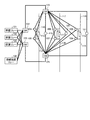
次に、本第1の実施形態の第3の変形例について説明する。図12に例示される計測装置600は、図3を用いて説明した第1の実施形態による計測装置500から通信インタフェース502を省き、通信インタフェースを1個のみにした例である。なお、図12において、上述の図3と共通する部分には同一の符号を付して、詳細な説明を省略する。
(Third Modification of First Embodiment)
Next, a third modification of the first embodiment will be described. A
計測装置600は、通信インタフェース501が受信したフレームをDEMUX506に対して出力すると共に、MUX505に入力されたフレームを通信インタフェース501に出力する点が、図3に例示した計測装置500と異なる。また、計測装置600は、受信したフレームの宛先アドレスがマルチキャストアドレスである場合に、そのフレームを転送しない。
The
この第3の変形例による計測装置600は、図11を用いて説明した、第2の変形例によるシングルスター型のネットワークで構成された送電線保護システムにおける計測装置104’〜109’として用いることができる。
The measuring
(第1の実施形態の第4の変形例)
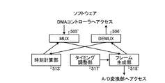
次に、本第1の実施形態の第4の変形例について説明する。図13−1に例示される計測装置700は、図3を用いて説明した第1の実施形態による計測装置500における一部の構成を、CPU512上で動作するソフトウェアで実現した例である。なお、図13−1および図13−2において、上述の図3と機能が共通する部分には同一の符号を付し、詳細な説明を省略する。
(Fourth modification of the first embodiment)
Next, a fourth modification of the first embodiment will be described. A
この例では、計測装置700は、図13−1に示されるように、ハードウェアとしては通信インタフェース501および502、ネットワーク処理部503、CPU512、記憶部514、水晶発振器515、DMAコントローラ516、A/D変換部519、ならびに、バス530を備える。CPU512、記憶部514、DMAコントローラ516およびA/D変換部519は、バス530により互いに通信可能に接続される。
In this example, as shown in FIG. 13A, the
そして、計測装置700は、図13−2に示されるように、MUX505’、DEMUX506’、時刻計算部513’、タイミング調整部517’およびフレーム生成部518’が、CPU512上で実行される図示されないOS(Operating System)上で動作するソフトウェアとしてそれぞれ構成される。これらMUX505’、DEMUX506’、時刻計算部513’、タイミング調整部517’およびフレーム生成部518’は、それぞれ、図3のハードウェアとしてのMUX505、DEMUX506、時刻計算部513、タイミング調整部517およびフレーム生成部518と同等の機能を実現する、CPU512上で動作されるソフトウェアのモジュールとして構成される。
Then, as shown in FIG. 13B, the
MUX505’およびDEMUX506’は、DMAコントローラ516にアクセスし、各種フレームの転送などを行う。フレーム生成部518’は、A/D変換部519にアクセスし、計測された物理量がディジタルデータとされた値を取り込む。
The MUX 505 'and the DEMUX 506' access the
例えば、MUX505’、DEMUX506’、時刻計算部513’、タイミング調整部517’およびフレーム生成部518’を構成するためのプログラムは、記憶部514記憶される。計測装置700の起動に伴い、CPU512は、ROMからプログラムを読み込んで実行することにより、各モジュールが図示されないRAM上に展開され、MUX505’、DEMUX506’、時刻計算部513’、タイミング調整部517’およびフレーム生成部518’がRAM上に構成される。
For example, a program for configuring the
本第4の変形例の計測装置700で実行されるプログラムは、例えば記憶部514に予め記憶されて提供される。これに限らず、当該プログラムを、ネットワークを介して計測装置700に対して提供してもよい。この場合、例えば、プログラムを含むフレームが通信インタフェース501または502に受信され、ネットワーク処理部503およびDMAコントローラ516を介して記憶部514に記憶される。
The program executed by the
これに限らず、当該プログラムを、インストール可能な形式または実行可能な形式のファイルでCD(Compact Disk)、フレキシブルディスク(FD)、DVD(Digital Versatile Disk)などのコンピュータで読み取り可能な記録媒体に記録されて提供されるようにもできる。この場合、バス530に対して記録媒体を読み取り可能なドライブ装置を接続する。そして、プログラムが記録された記録媒体をこのドライブ装置に装着し、記録媒体からプログラムを読み出して記憶部514に記憶させる。
Not limited to this, the program is recorded in a computer-readable recording medium such as a CD (Compact Disk), a flexible disk (FD), and a DVD (Digital Versatile Disk) in a file in an installable or executable format. Can also be provided. In this case, a drive device that can read the recording medium is connected to the
このように、計測装置700が有する一部の機能をCPU512上で動作するソフトウェアとして実装することで、ハードウェアで全てが構成される計測装置500に対し、回路規模を削減することができる。なお、本第4の変形例による計測装置700は、計測タイミングの調節と物理量の送信を別々のタイミングで行うことができる。これは、上述した第1の実施形態による計測装置500および第3の変形例による計測装置600においても同様である。
As described above, by implementing a part of the functions of the
さらに、本第4の変形例による計測装置700において、上述の第3の変形例による計測装置600の如く、通信インタフェース502を省略し1の通信インタフェース501のみを備える構成とすることもできる。
Further, in the
(第2の実施形態)
第2の実施形態における計測装置は、計測装置に搭載された水晶発振器に従って定期的に物理量を計測し、物理量の値を記述したフレーム(物理量データフレーム)を、保護リレーおよび母線保護リレーに対して送信する。本第2の実施形態では、第1の実施形態における計測装置とは異なり、保護リレーの時刻に従った計測タイミングを調整しない。したがって、複数の計測装置から同じ保護リレーに送信される物理量は、同じタイミングで計測されない可能性がある。
(Second Embodiment)
The measurement device according to the second embodiment periodically measures a physical quantity according to a crystal oscillator mounted on the measurement device, and sends a frame (physical quantity data frame) describing the value of the physical quantity to the protection relay and the bus protection relay. Send. In the second embodiment, unlike the measurement device in the first embodiment, the measurement timing according to the time of the protection relay is not adjusted. Therefore, physical quantities transmitted from a plurality of measuring devices to the same protection relay may not be measured at the same timing.
そこで、本第2の実施形態では、計測装置が、保護リレーおよび母線保護リレーに対し、計測装置の時刻を記述したフレーム(以下では、SyncメッセージBと呼ぶ)を定期的に送信する。また、計測装置は、物理量データフレームに物理量の計測時刻を記述する。そして第2の実施形態に係る保護リレーおよび母線保護リレーは、それぞれの計測装置から受信したSyncメッセージBに記述された時刻を用いて、物理量データフレームの送信元である全ての計測装置の時刻を把握する。また、保護リレーおよび母線保護リレーは、物理量データフレームに記述された物理量の計測時刻を自身の時刻に変換する。 Therefore, in the second embodiment, the measuring device periodically transmits a frame describing the time of the measuring device (hereinafter referred to as Sync message B) to the protection relay and the busbar protection relay. Further, the measuring device describes the measurement time of the physical quantity in the physical quantity data frame. The protection relay and bus protection relay according to the second embodiment use the time described in the Sync message B received from each measurement device to set the time of all measurement devices that are the transmission source of the physical quantity data frame. To grasp. Further, the protection relay and the busbar protection relay convert the physical quantity measurement time described in the physical quantity data frame into its own time.
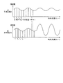
以上により、本第2の実施形態による保護リレーおよび母線保護リレーは、複数の計測装置が物理量を計測した時刻の関係を把握する。例えば、1の保護リレーに物理量データフレームを送信する2の計測装置Aおよび計測装置Bを考える。この場合、図14に示すように、計測装置Aにおける計測タイミングt1、t2、…と、計測装置Bにおける計測タイミングt’1、t’2、…とが互いに異なることが考えられる。 As described above, the protection relay and the busbar protection relay according to the second embodiment grasp the relationship between the times when the plurality of measuring devices measure the physical quantity. For example, consider two measuring devices A and B that transmit a physical quantity data frame to one protective relay. In this case, as shown in FIG. 14, the measurement timings t 1 , t 2 ,... In the measurement apparatus A and the measurement timings t ′ 1 , t ′ 2 ,.
計測装置Aおよび計測装置Bそれぞれから、計測装置Aと計測装置Bとで異なるタイミングで計測された物理量の値が記述された物理量データフレームが保護リレーに受信される。保護リレーは、計測装置Aにおける計測タイミングt1、t2、…と、計測装置Bにおける計測タイミングt’1、t’2、…とを、それぞれ保護リレーの時刻に換算することで、計測装置Aおよび計測装置Bそれぞれの計測タイミングの関係を把握することができる。そこで、保護リレーは、計測装置Aおよび計測装置Bそれぞれの物理量の値による時系列データを比較することで、過電流等の異常の有無を検証できる。 From each of the measuring device A and the measuring device B, a physical quantity data frame in which values of physical quantities measured at different timings in the measuring device A and the measuring device B are received by the protection relay. The protective relay converts the measurement timings t 1 , t 2 ,... In the measuring device A and the measurement timings t ′ 1 , t ′ 2 ,. The relationship between the measurement timings of A and the measurement apparatus B can be grasped. Therefore, the protection relay can verify the presence / absence of an abnormality such as an overcurrent by comparing time-series data based on the physical quantity values of the measuring device A and the measuring device B.
以下、第2の実施形態における送電線保護システムについて、より詳細に説明する。なお、本第2の実施形態に対し、上述した第1の実施形態における図1、図10および図11を用いて説明したシステム構成をそのまま適用できるので、システム構成の説明を省略する。以下では、図1で示したリング型ネットワークを本第2の実施形態に適用したものとして説明を行う。すなわち、第2の実施形態による送電線保護システムは、保護リレー101〜103、計測装置104〜109、遮断器110〜112、開閉器113〜115、送電線116〜118、母線保護リレー130、ならびに、遮断器コントローラ119〜121を含む。また、保護リレー101〜103、計測装置104〜109、母線保護リレー130、ならびに、遮断器コントローラ119〜121は、リング型ネットワークを構成する。
Hereinafter, the power transmission line protection system according to the second embodiment will be described in more detail. Note that the system configuration described with reference to FIGS. 1, 10, and 11 in the first embodiment described above can be applied to the second embodiment as it is, and thus the description of the system configuration is omitted. In the following description, it is assumed that the ring network shown in FIG. 1 is applied to the second embodiment. That is, the power transmission line protection system according to the second embodiment includes protection relays 101 to 103, measuring
本第2の実施形態における計測装置104〜109は、例えば図2に示す関係に従い、保護リレー101〜103、ならびに、母線保護リレー130に対して、物理量データフレームをネットワークを介して送信する。また、上述した第1の実施形態とは異なり、本第2の実施形態における計測装置104〜109は、例えば図2に示す関係に従い、保護リレー101〜103、ならびに、母線保護リレー130に対して、時刻を記したSyncメッセージBをネットワークを介して送信する。また、本第2の実施形態においては、上述した第1の実施形態とは異なり、保護リレー101〜103および母線保護リレー130は、時刻を記述したSyncメッセージを計測装置104〜109に対して送信しなくてもよい。
The
計測装置104〜109が物理量データフレームを送信する間隔は、それぞれの計測装置に搭載された水晶発振器に従った一定時間間隔であってもよいし、可変でもよい。ただし、送信先の保護リレーが物理量の変化を十分に把握できるよう、計測装置104〜109は、十分な頻度で物理量を計測し、物理量データフレームを保護リレーへ送信する。また、計測装置104〜109がSyncメッセージBを送信する間隔は、それぞれの計測装置に搭載された水晶発振器に従った一定時間間隔であってもよいし、可変でもよい。
The interval at which the
また、典型的な変電所に本第2の実施形態を適用する場合、計測装置は、自身の時刻をマルチキャストで定期的に送信する。これに限らず、計測装置104〜109は、ユニキャストを用いて自身の時刻を、図2に示す関係に従った保護リレーまたは母線保護リレーに対して定期的に送信してもよい。
In addition, when the second embodiment is applied to a typical substation, the measurement device periodically transmits its own time by multicast. Not limited to this, the measuring
なお、保護リレー101〜103、計測装置104〜109、ならびに、母線保護リレー130の対応関係は、図2に示す関係に限られるものではなく、他の組み合わせであってもよい。特に、各計測装置104〜109が物理量データフレームを送信する送信先の保護リレー数は、異なっていてもよい。この場合であっても、本第2の実施形態においては、各計測装置104〜109は、少なくとも、物理量データフレームの送信先である保護リレー101〜103、または、母線保護リレー130に対してSyncメッセージBを送信する。
Note that the correspondence relationship between the protection relays 101 to 103, the measuring
本第2の実施形態においては、保護リレー101〜103、ならびに、母線保護リレー130が計測装置104〜109の時刻を取得する方法は、特に限定されない。例えば、保護リレー101〜103、計測装置104〜109、ならびに、母線保護リレー130は、IEEE1588またはNTPに準拠した機能を備えてもよい。第2の実施形態では、保護リレー101〜103、計測装置104〜109、ならびに、母線保護リレー130がIEEE1588の1step方式およびPeer delay mechanismと呼ばれる方式に準拠する場合の例を説明する。
In the second embodiment, the method for the protection relays 101 to 103 and the
すなわち、保護リレー101〜103、計測装置104〜109、ならびに、母線保護リレー130がSyncメッセージBを送信または転送するとき、転送処理にかかる推定時間をSyncメッセージBに記述する。また、保護リレー101〜103、計測装置104〜109、ならびに、母線保護リレー130は、隣接する機器へPdelay_Reqメッセージを送信する機能、および隣接機器からPdelay_Reqメッセージを受信し、Pdelay_Responseメッセージを返送する機能、およびPdelay_Responseメッセージを受信し、隣接機器との間のケーブル中の伝送遅延時間を計算する機能を備える。
That is, when the protection relays 101 to 103, the measuring
Pdelay_Reqメッセージは、Pdelay_Reqメッセージ送信時の時刻を示す情報が記述される。また、Pdelay_Responseメッセージには、Pdelay_Reqメッセージ受信時の時刻およびPdelay_Responseメッセージ送信時の時刻を示す情報が記述される。 In the Pdelay_Req message, information indicating the time when the Pdelay_Req message is transmitted is described. In the Pdelay_Response message, information indicating the time when the Pdelay_Req message is received and the time when the Pdelay_Response message is transmitted is described.
なお、第2の実施形態において、図1の保護リレー101〜103、計測装置104〜109、ならびに、母線保護リレー130以外の動作は、上述した第1の実施形態における動作と同様であるので、ここでの詳細な説明を省略する。
In the second embodiment, operations other than the protection relays 101 to 103, the
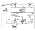
図15において、保護リレー1400は、例えば図1に示した保護リレー101〜103、ならびに、母線保護リレー130に該当する。本第2の実施形態に係る保護リレー1400は、通信インタフェース1401および1402、ネットワーク処理部1403、MUX1406、DEMUX1405、CPU1407、時刻計算部1409、記憶部1412、DMAコントローラ1408、水晶発振器1404、タイムスタンプ補正部1410、ならびに、リレー演算部1411を備える。
In FIG. 15, a
CPU1407は、例えば汎用のプロセッサであり、記憶部1412に記憶されたプログラムに従い、同じく図示されないRAMをワークメモリとして、この保護リレー1400の全体の動作を制御する。バス1430は、CPU1407、時刻計算部1409、記憶部1412、DMAコントローラ1408、タイムスタンプ補正部1410およびリレー演算部1411を接続することで、互いに通信可能にする。
The
図15に示される通信インタフェース1401および1402、ネットワーク処理部1403、水晶発振器1404、CPU1407、ならびに、DMAコントローラ1408の動作は、例えば図3に示した計測装置500における通信インタフェース501および502、ネットワーク処理部503、水晶発振器515、CPU512、ならびに、DMAコントローラ516と同等であるので、ここでの詳細な説明を省略する。
The operations of the
DEMUX1405は、ネットワーク処理部1403から出力されたSyncメッセージBを、時刻計算部1409に転送する。また、DEMUX1405は、ネットワーク処理部1403から出力された物理量データフレームを、タイムスタンプ補正部1410に転送する。さらに、DEMUX1405は、ネットワーク処理部1403から出力された他のメッセージを、DMAコントローラ1408に転送する。これに限らず、DEMUX1405は、SyncメッセージBおよび物理量データフレームのうち少なくとも一方を、さらにDMAコントローラ1416に対して出力してもよい。
The
MUX1406は、DMAコントローラ1408、時刻計算部1409およびリレー演算部1411の何れかからフレームを取得し、ネットワーク処理部503に対して転送する。時刻計算部1409は、入力されたSyncメッセージBに記述されたSyncメッセージBの送信時刻を利用して、SyncメッセージBの送信元である計測装置のクロックの時刻を計算する。また、時刻計算部1409は、記憶部1412に対し、計測装置の時刻を保護リレー1400の時刻に変換するためのパラメータ(以下、変換パラメータBと呼ぶ)を保存する。
The
タイムスタンプ補正部1410は、計測装置から受信した物理量データフレームに記述された計測時刻を、保護リレー1400の時刻に変換する。
The time
リレー演算部1411は、記憶部1412に保存した物理量の時系列データと、計測装置から受信した最新の物理量データフレームに記述された物理量と、当該物理量の計測時刻を保護リレー1400の時刻に変換した値とを用いて、送電線における異常を検証する。記憶部1412は、送信先の計測装置それぞれに対する計測装置のアドレス、変換パラメータBおよび物理量の時系列データを保持する。
The
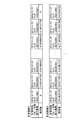
図16および図17は、記憶部1412が保持するデータの例を示す。図16は、計測装置の時刻を保護リレー1400の時刻に変換するために必要なデータの例を示す。このデータは、送信元の計測装置毎のレコードからなるテーブルとして記憶部1412に保存される。各レコードは、インデックスで識別される。計測装置のアドレスは、当該保護リレー1400が計測装置にアクセスする際に用いるアドレスであって、例えばイーサネット(登録商標)のMACアドレスや、IPアドレスを用いることができる。
16 and 17 show examples of data held by the
変換パラメータBは、例えばクロックレート、SyncメッセージB受信時の計測装置の時刻およびSyncメッセージB受信時のリレー1400の時刻を含む。クロックレートは、保護リレー1400における時刻の進行速度と、計測装置における時刻の進行速度との違いを表す。換言すれば、保護リレー1400における水晶発振器1404から出力されるクロックカウンタにより規定される例えば1秒と、計測装置において時刻を計測するクロックにより規定される1秒との違いを知ることができる。
The conversion parameter B includes, for example, the clock rate, the time of the measuring device when the Sync message B is received, and the time of the
例えば、クロックレートC_rateは、SyncメッセージBの送信元の計測装置における1秒の長さSecond_mに対する保護リレー1400における1秒の長さSecond_rの割合を求め、スケールを調整した値であり、下記の式(9)により計算される。
C_rate=Second_r/Second_m×scale …(9)
For example, the clock rate C_rate is a value obtained by adjusting the scale by obtaining the ratio of the length Second_r of 1 second in the
C_rate = Second_r / Second_m × scale (9)
なお、値scaleは、予め決められた値であり、整数演算で計算が容易なようにクロックレートC_rateのスケールを調整するために用いられる。 Note that the value scale is a predetermined value, and is used to adjust the scale of the clock rate C_rate so that it can be easily calculated by integer arithmetic.
図17は、物理量の時系列データの例を示す。保護リレー1400の時刻に換算した計測時刻と、当該計測時刻に計測された物理量の値とが対応付けられて、計測時刻保持される。この時系列データが、当該保護リレー1400に対する物理量データフレームの転送元の計測装置A、Bなどそれぞれについて、保持される。
FIG. 17 shows an example of time-series data of physical quantities. The measurement time converted to the time of the
図18は、本第2の実施形態に適用可能な計測装置800の一例の構成を示す。なお、図18において、上述した図3の計測装置500と共通する部分には同一の符号を付し、詳細な説明を省略する。また、以下では、図18について、上述の図3の構成と異なる部分についてのみ、説明する。この図18に示される計測装置800は、上述した図1の計測装置104〜109に対応する。
FIG. 18 shows an exemplary configuration of a measuring
図18に示される計測装置800は、図3に示した計測装置500と比較して、時刻計算部513およびタイミング調整部517が削除されている代わりに、時刻提供部2313が備えられている。時刻提供部2313は、水晶発振器515から出力されるクロックカウンタに基づき、定期的にSyncメッセージBを生成する。生成されたSyncメッセージBは、MUX505を介してネットワーク処理部503に転送され、通信インタフェース501により送信される。
A measuring
また、時刻提供部2313は、Pdeley_ReqメッセージおよびPdeley_Responseメッセージを生成する。生成されたPdeley_ReqメッセージおよびPdeley_Responseメッセージは、MUX505を介してネットワーク処理部503に転送され、通信インタフェース501または502により送信される。さらに、時刻提供部2313は、通信インタフェース501または502により受信され且つネットワーク処理部503およびDEMUX506を介して転送されたPdeley_ReqメッセージおよびPdeley_Responseメッセージを、処理する。
The
次に、本第2の実施形態に係る保護リレーの処理を説明する。図19は、計測装置107が保護リレー102に対して物理量データフレームを送信する際の一例の処理を示すシーケンス図である。上述の図1を参照し、計測装置107から出力された物理量データフレームは、計測装置104および105を介して保護リレー101に転送され、さらに、保護リレー101から保護リレー102に対して転送される。なお、途中の計測装置104および105における処理は、上述した計測装置105における処理と同等なので、ここでの説明を省略する。
Next, the protection relay process according to the second embodiment will be described. FIG. 19 is a sequence diagram illustrating an example of processing when the measuring
図19に示すシーケンスは、第1、第2および第3の、3のシーケンスに分類される。第1のシーケンスは、計測装置107が送信したSyncメッセージBを保護リレー102が受信し、保護リレー102が計測装置107の時刻を把握する。第2のシーケンスは、保護リレー102が隣接する機器との間のネットワーク上における通信遅延を定期的に測定する。第3のシーケンスは、計測装置107が保護リレー102に対して物理量データフレームを送信する。
The sequence shown in FIG. 19 is classified into first, second, and third sequences. In the first sequence, the
なお、これら第1〜第3のシーケンスは、それぞれ独立したタイミングで実行されてもよく、第1〜第3のシーケンスがどのような順番で行われてもよい。また、本第2の実施形態では、第2のシーケンスを必ずしも実行する必要はない。第2のシーケンスは、SyncメッセージBの転送遅延時間を高精度に計測するために実行されるもので、第2のシーケンスを実行することで、保護リレーが計測装置の時刻を高精度に把握することができる。高精度が必要ない場合は、第2のシーケンスの実行を省略可能である。 Note that these first to third sequences may be executed at independent timings, and the first to third sequences may be executed in any order. In the second embodiment, it is not always necessary to execute the second sequence. The second sequence is executed in order to measure the transfer delay time of the Sync message B with high accuracy. By executing the second sequence, the protection relay grasps the time of the measuring device with high accuracy. be able to. When high accuracy is not required, the execution of the second sequence can be omitted.
先ず、第1のシーケンスについて説明する。計測装置107は、SyncメッセージB2001を送信する(ステップS2051)。SyncメッセージB2001の宛先アドレスは、保護リレー102のアドレス若しくはマルチキャストアドレスである。このSyncメッセージB2001は、遮断器コントローラ119、計測装置104および計測装置105それぞれにより順次転送され(図示しない)、保護リレー101に受信される。
First, the first sequence will be described. The measuring
遮断器コントローラ119、計測装置104および計測装置105は、SyncメッセージB2001を転送する際に、SyncメッセージB2001に含まれるCorrectionフィールドの値を、下記の式(10)で計算される値D_new_correctionで置き換えてもよい。
D_new_correction=D_trans+D_old_correction+D_pdelay …(10)
When the
D_new_correction = D_trans + D_old_correction + D_pdelay (10)
なお、式(10)において、値D_transは、SyncメッセージB2001の転送処理時間を示す。値D_old_correctionは、元のSyncメッセージB2001のCorrectionフィールドに記述されていた値を示す。値D_pdelayは、SyncメッセージB2001を受信した通信インタフェースと、ケーブルで接続された隣接装置との間の通信遅延を示す。 In Expression (10), the value D_trans indicates the transfer processing time of the Sync message B2001. The value D_old_correction indicates a value described in the Correction field of the original Sync message B2001. The value D_pdelay indicates a communication delay between the communication interface that has received the Sync message B2001 and an adjacent device connected by a cable.
保護リレー101は、ステップS2052で、SyncメッセージB2001を保護リレー102に転送する。ステップS2052における保護リレー101における転送処理は、図6のステップS752で説明した、第1の実施形態の計測装置105における処理と同様にして行われる。ステップS2052において、保護リレー101は、値D_new_correctionの値を計算し、Correctionフィールドに記述してもよい。
The
保護リレー102は、保護リレー101から転送されたSyncメッセージB2001を受信する(ステップS2053)。そして、保護リレー101は、受信したSyncメッセージB2001から、計測装置107の時刻およびクロックレートを把握する。
The
ステップS2053における保護リレー102の動作を、図15を参照しながら説明する。保護リレー102(保護リレー1400)において、通信インタフェース1401がSyncメッセージB2001を受信したと想定する。通信インタフェース1401は、SyncメッセージB2001をネットワーク処理部1403に対して出力する。ネットワーク処理部1403は、水晶発振器1404から出力されたクロックカウンタを、タイムスタンプとして取得する。
The operation of the
SyncメッセージB2001の宛先アドレスはリレー1400のアドレスか、またはマルチキャストアドレスであるため、ネットワーク処理部1403は、SyncメッセージB2001をDEMUX1405に対して出力する。SyncメッセージB2001の宛先アドレスがマルチキャストアドレスの場合、ネットワーク処理部1403は、さらに通信インタフェース1402に対してSyncメッセージB2001を出力する。その後の処理は、図6のステップ752における処理と同様であるので、ここでの説明を省略する。
Since the destination address of Sync message B2001 is the address of
次に、DEMUX1405は、SyncメッセージB2001の出力先を決定する。DEMUX1405は、入力されたフレームがSyncメッセージB、Pdelay_Reqメッセ0時またはPdelay_Responseメッセージである場合に、当該フレームを時刻計算部1409に対して出力し、DEMUX1405は、入力されたフレームが物理量データフレームであれば、当該フレームをタイムスタンプ補正部1410へ出力し、それら以外のフレームを全てDMAコントローラ1408に対して出力する。ここでは、SyncメッセージB2001のフレームが入力されたため、DEMUX1405は、入力されたSyncメッセージB2001を、時刻計算部1409に対して出力する。
Next, the
時刻計算部1409は、ネットワーク処理部1403から、SyncメッセージB2001受信時の時刻を示すクロックカウンタを取得する。そして、時刻計算部1409は、SyncメッセージB2001に記載されたSyncメッセージB2001の送信時刻T_sync_sendとすると、SyncメッセージB2001受信時のクロックカウンタC_sync_recvと、SyncメッセージB2001の通信遅延D_syncと、記憶部1412に保存していた、前回SyncメッセージBを受信した際の計測装置の時刻と、保護リレー102の時刻とを用いて、クロックレートを計算する。
The
なお、通信遅延D_syncは、予め決められた値を用いてもよい。また、通信遅延D_syncは、SyncメッセージB2001のCorrectionフィールドに記された値を用いてもよい。さらに、通信遅延D_syncは、SyncメッセージB2001のCorrectionフィールドに記された値に、後述する第2のシーケンスで計測した、保護リレー102と保護リレー101との間の通信遅延を加えた値を用いてもよい。
A predetermined value may be used for the communication delay D_sync. The communication delay D_sync may be a value written in the Correction field of the Sync message B2001. Further, the communication delay D_sync is obtained by adding a communication delay between the
時刻計算部1409は、クロックレートを例えばPI制御、回帰解析、線形計画法などの方法で計算することができる。なお、時刻計算部1409は、前回のSyncメッセージBを受信した以前に受信した、1以上のSyncメッセージBを受信した際の計測装置および保護リレー1400の時刻を記憶部1412に保存しておくことができる。時刻計算部1409は、前回のSyncメッセージBを受信した際の計測装置および保護リレー1400の時刻を用いると共に、記憶部1412に保存されたこれら1以上の計測装置および保護リレー1400の時刻を用いて、クロックレートを計算してもよい。これにより、回帰解析、線形計画法などの方法を用いる場合に、クロックレートを精度良く推測できる。
The
時刻計算部1409は、算出されたクロックレートを、記憶部1412に保存する(図16参照)。また、時刻計算部1409は、下記の式(11)により、SyncメッセージB2001の受信時における計測装置107の時刻T_sync_est_recvを計算し、記憶部1412に保存する(図16参照)。
T_sync_est_recv=T_sync_send+D_sync …(11)
The
T_sync_est_recv = T_sync_send + D_sync (11)
さらに、時刻計算部1409は、下記の式(12)により、SyncメッセージB2001の受信時における保護リレー1400の時刻T_sync_recv_rを計算し、記憶部1412に保存する(図16参照)。
T_sync_recv_r=T_origin+C_sync_recv×f …(12)
Further, the
T_sync_recv_r = T_origin + C_sync_recv × f (12)
なお、値T_originは前回SyncメッセージBを計測装置107から受信したときに計算した値T_sync_recv_rである。但し、SyncメッセージB2001が保護リレー107から初めて受信したSyncメッセージBである場合、T_originは例えばクロックカウンタが「0」のときの保護リレーの時刻である。以上が、ステップS2053における保護リレー102の処理である。
The value T_origin is the value T_sync_recv_r calculated when the previous Sync message B was received from the measuring
次に、第2のシーケンスについて説明する。第2のシーケンスでは、隣接機器間の遅延を測定する。保護リレー102は、定期的にPdelay_Reqメッセージを隣接する保護リレー101に送信し、保護リレー101からPdelay_Responseメッセージを受信する。
Next, the second sequence will be described. In the second sequence, a delay between adjacent devices is measured. The
図19において、ステップS2054で保護リレー102から保護リレー101に対してPdelay_Reqメッセージ2002が送信され、このPdelay_Reqメッセージ2002に応じて、ステップS2055で、保護リレー101からPdelay_Reqメッセージ2003が返され、ステップS2056で保護リレー102に受信される。このステップS2054〜ステップS2056の処理は、それぞれ図6に示す第1の実施形態におけるステップS754〜ステップS756における処理と同様であるので、ここでの詳細な説明を省略する。なお、隣接機器間の遅延測定は、任意の隣接機器間で計測してもよい。
In FIG. 19, a
次に、第3のシーケンスについて説明する。第3のシーケンスでは、保護リレー102が計測装置107から物理量データフレームを受信する。先ず、計測装置107は、物理量データフレーム2007を送信する(ステップS2057)。この物理量データフレームは、遮断器コントローラ119、計測装置104、および計測装置105により順次転送されて、保護リレー101に受信される。保護リレー101は、受信した物理量データフレームを、保護リレー102に対して転送する(ステップS2058)。このステップS2058での保護リレー101における処理は、上述の第1の実施形態による、図6のステップS758での計測装置105における処理と同様なので、ここでの詳細な説明を省略する。
Next, the third sequence will be described. In the third sequence, the
ステップS2059で、保護リレー102は、物理量データフレーム2007を受信し、送電線117における異常の有無を検証する。このステップS2059における保護リレー102の動作を、図15および図20を用いて説明する。
In step S2059, the
先ず、図20に示すように保護リレー102(保護リレー1400)は物理量データフレーム2007を受信する(ステップS2101)。ここでは、通信インタフェース1401が物理量データフレーム2007を受信したと想定する。通信インタフェース1401は、受信した物理量データフレーム2007を、ネットワーク処理部1403に対して出力する、物理量データフレーム2007の宛先アドレスは、保護リレー102のアドレス若しくはマルチキャストアドレスである。そのため、ネットワーク処理部1403は、物理量データフレーム2007を、DEMUX1405に対して出力する。
First, as shown in FIG. 20, the protection relay 102 (protection relay 1400) receives the physical quantity data frame 2007 (step S2101). Here, it is assumed that the
なお、物理量データフレーム2007の宛先アドレスがマルチキャストアドレスの場合、ネットワーク処理部1403は、物理量データフレーム2007を通信インタフェース1402に対して出力する。そして通信インタフェース1402は物理量データフレーム2007をネットワークへ送信する。ら出力された物理量データフレーム2007をネットワークに対して送信する。
If the destination address of the physical
次に、DEMUX1405は物理量データフレーム2007をタイムスタンプ補正部1410に対して出力する(ステップS2102)。タイムスタンプ補正部1410は、物理量データフレーム2007に記述された時刻を、リレー1400の時刻に変換する。
Next, the
ステップS2102における時刻の変換処理方法を以下で詳しく説明する。先ず、タイムスタンプ補正部1410は、物理量データフレーム2007の送信元アドレスに一致するレコードを、図17に示すテーブルから検索する。タイムスタンプ補正部1410は、テーブルから検索されたレコードから、クロックレートC_rateと、前回Syncメッセージ2007を受信したときの計測装置107の時刻で換算した時刻T_sync_est_recvと、保護リレー1400の時刻T_sync_recv_rとを取得する。
The time conversion processing method in step S2102 will be described in detail below. First, the time
次に、タイムスタンプ補正部1410は、スケール値scaleと、クロックレートC_rateと、時刻T_sync_est_recvと、時刻T_sync_recv_rとを用いて、下記の式(13)および式(14)により、物理量データフレーム2007に記載された計測時刻T_measured_mを保護リレー1400の時刻T_measured_rに変換し、記憶部1412に保存する。
D_from_sync=(T_measured_m−T_sync_est_recv)×C_rate/scale …(13)
T_measured_r=T_sync_recv_r+D_from_sync …(14)
Next, the time
D_from_sync = (T_measured_m−T_sync_est_recv) × C_rate / scale (13)
T_measured_r = T_sync_recv_r + D_from_sync (14)
なお、値D_from_syncは、以前のSyncメッセージB2001の受信時から物理量データフレーム2007送信時までの時間を、保護リレー1400の時刻に換算した時間である。
The value D_from_sync is a time obtained by converting the time from when the previous Sync message B2001 is received to when the physical
次に、リレー演算部1411は、記憶部1412に保存された時系列データを用いて送電線117における異常の有無を検証する(ステップS2103)。記憶部1412に保存された時系列データの計測時刻は、全て保護リレー1400の時刻で換算した時刻である。そのため、リレー演算部1411は、複数の計測装置から得た時系列データ同士を比較可能である。異常検知に用いるアルゴリズムは、特に限定されない。例えば、リレー演算部1411は計測装置106から得た時系列データと計測装置107から得た時系列データとの間に大きな差があるとき、送電線117に異常があると判断することができる。
Next, the
次に、ステップS2104においてリレー演算部1411の処理はステップS2103の検証結果に基づき分岐する。若し、ステップS2103で、リレー演算部1411が送電線117に異常がないと判定した場合、この図20のフローチャートによる一連の処理が終了され、保護リレー1400は、第3のシーケンスにおける処理を終える。
Next, in step S2104, the processing of the
一方、ステップS2103において、リレー演算部1411が送電線117に異常があると判定した場合、保護リレー1400は、遮断指令メッセージを遮断器コントローラ120に対して送信する(ステップS2105)。より詳細には、ステップS2105において、リレー演算部1411は、CPU1407に対して割り込みをかける。この割り込みに応じて、CPU1407は、記憶部1412に記憶されたプログラムに従い、遮断を指令するためのメッセージ(以下、遮断指令メッセージと呼ぶ)を生成する。
On the other hand, when the
次に、CPU1407は、DMAコントローラ1408に、遮断指令メッセージを送信するよう指令する。MUX1406は、DMAコントローラ1408から遮断指令メッセージを取得し、ネットワーク処理部1403に対して出力する。ネットワーク処理部1403は、MAC処理を行い、通信インタフェース1401および通信インタフェース1402に対して遮断指令メッセージを出力する。通信インタフェース1401および通信インタフェース1402は、遮断指令メッセージを遮断器コントローラ120に対して送信する。遮断器コントローラ120は、遮断指令メッセージを受信すると、遮断器111に対して遮断信号を送出する。遮断器111は、遮断信号を受信すると、送電線117の電気を遮断する。
Next, the
以上のように、本第2の実施形態によれば、異なる計測装置が異なるタイミングで物理量を計測しても、物理量データフレームを受信する保護リレーは、計測時刻を保護リレーの時刻に換算するため、時系列データ同士を比較できる。そのため、システム内の全ての機器に時刻を配信する時刻サーバが必要ないという利点がある。 As described above, according to the second embodiment, even if different measurement devices measure physical quantities at different timings, the protection relay that receives the physical quantity data frame converts the measurement time into the protection relay time. Time series data can be compared. Therefore, there is an advantage that there is no need for a time server that distributes the time to all devices in the system.
また、例えば保護リレー102が故障するか、保護リレー102の時刻に異常が生じても、母線保護リレー130に影響を及ぼさないため、母線保護リレー130は、複数の計測装置から得た物理量の時系列データを正しく比較できる。そのため、本第2の実施形態に係る保護リレーおよび母線保護リレーを用いることで、変電所の信頼性を向上できる。
Further, for example, even if the
さらに、本第2の実施形態に係る保護リレーおよび母線保護リレーを送電線保護システムに導入することによって、計測装置は、物理量の送信先であるそれぞれの保護リレーおよび母線保護リレー毎にPLLを備える必要がない。そのため、システムの拡張が容易である。これに対して、物理量データフレームの送信先の装置毎に1のPLLを計測装置に備えることで計測タイミングを決定する方法では、計測装置が備えるPLLの数に送信先の装置数が制限されてしまい、拡張性に欠ける。 Furthermore, by introducing the protection relay and the busbar protection relay according to the second embodiment into the power transmission line protection system, the measuring device includes a PLL for each protection relay and busbar protection relay that is a transmission destination of the physical quantity. There is no need. Therefore, the system can be easily expanded. On the other hand, in the method of determining the measurement timing by providing one PLL for each transmission destination device of the physical quantity data frame in the measurement device, the number of transmission destination devices is limited to the number of PLLs included in the measurement device. Therefore, it lacks extensibility.
また、本第2の実施形態では、保護リレーや母線保護リレーと、計測装置とを1対1で接続する必要がない。そのため変電所の要件に応じて柔軟なネットワークを構成可能である。例えば、本第2の実施形態による送電線保護システムは、図10を用いて説明した、ダブルスター型のネットワークにより構成することができる。この場合、本第2の実施形態に係る保護リレーおよび母線保護リレーの動作は、受信したフレームの宛先アドレスがマルチキャストアドレスであるか自身のアドレスでない場合にそのフレームを転送しないこと以外、本第2の実施形態と同様である。また、本第2の実施形態による送電線保護システムは、図11を用いて説明したシングルスター型のネットワークによっても構成可能である。 Further, in the second embodiment, it is not necessary to connect the protection relay and the busbar protection relay and the measuring device on a one-to-one basis. Therefore, a flexible network can be configured according to the requirements of the substation. For example, the power transmission line protection system according to the second embodiment can be configured by the double star network described with reference to FIG. In this case, the operation of the protection relay and the bus protection relay according to the second embodiment is the same as that of the second embodiment except that the frame is not transferred when the destination address of the received frame is a multicast address or not its own address. This is the same as the embodiment. The power transmission line protection system according to the second embodiment can also be configured by a single star type network described with reference to FIG.
なお、本第2の実施形態に係る送電線保護システムは、時刻に関するデータの送受信量を低減できる。典型的な変電所では、時刻を把握する頻度は、物理量を送信する頻度よりも低い。一方、第2の実施形態に係る保護リレーおよび母線保護リレーは、計測装置の時刻の把握と送電線における異常の検証とを、別のシーケンスで行うため、時刻に関するデータの送受信量を低減できる。 Note that the power transmission line protection system according to the second embodiment can reduce the amount of data transmitted and received regarding time. In a typical substation, the frequency of grasping the time is lower than the frequency of transmitting physical quantities. On the other hand, the protection relay and the busbar protection relay according to the second embodiment perform the grasping of the time of the measuring device and the verification of the abnormality in the power transmission line in different sequences, so that it is possible to reduce the amount of data transmitted and received regarding the time.
これに限らず、本第2の実施形態に係る保護リレーおよび母線保護リレーは、SyncメッセージBと物理量データフレームとを1のメッセージに纏めた統合メッセージを処理してもよい。統合メッセージは、物理量の値と、統合メッセージの送信時刻と、Correctionフィールドとを含む。保護リレー1400の時刻計算部1409は、統合メッセージの送信時刻およびCorrectionフィールドの値をSyncメッセージBによる送信時刻およびCorrectionフィールドの値の代わりに利用して、計測装置の時刻を把握する。また、保護リレー1400のタイムスタンプ補正部1410は、統合メッセージの送信時刻および物理量の値を、物理量データフレームの代わりに利用する。
However, the protection relay and bus protection relay according to the second embodiment may process an integrated message in which the Sync message B and the physical quantity data frame are combined into one message. The integrated message includes a physical quantity value, a transmission time of the integrated message, and a Correction field. The
また、本第2の実施形態に係る保護リレー1400の時刻計算部1409は、通信インタフェース1401と通信インタフェース1402との間で転送されるSyncメッセージBを処理してもよい。この場合、SyncメッセージBは、ネットワーク処理部1403およびDEMUX1405を経由して、時刻計算部1409に転送される。時刻計算部1409は、推定される転送処理時間を計算し、その値をSyncメッセージBに対して記述する。
The
そして、時刻計算部1409は、SyncメッセージBを、MUX1406およびネットワーク処理部1403を介して、当該SyncメッセージBを受信した通信インタフェースとは別の通信インタフェースから出力する。SyncメッセージBの処理を時刻計算部1409に全て集約することで、保護リレーおよび母線保護リレーの回路規模を低減できる。
Then, the
(第2の実施形態の第1の変形例)
次に、本第2の実施形態の第1の変形例について説明する。この図21に例示される保護リレー1500は、図15を用いて説明した第2の実施形態による保護リレー1400から通信インタフェース1402を省き、通信インタフェースを1個のみにした例である。なお、図21において、上述の図15と共通する部分には同一の符号を付して、詳細な説明を省略する。
(First Modification of Second Embodiment)
Next, a first modification of the second embodiment will be described. The
保護リレー1500は、通信インタフェース1401が受信したフレームをDEMUX1405に出力すると共に、MUX1406に入力されたフレームを通信インタフェース1401に出力する点が、図15に例示した保護リレー1400と異なる。また、保護リレー1500は、通信インタフェース1401が受信したフレームの宛先アドレスがマルチキャストアドレスである場合に、そのフレームを転送しない。
The
本第2の実施形態の第1の変形例による保護リレー1500は、図11を用いて説明した、シングルスター型のネットワークで構成された送電線保護システムにおける保護リレー101’〜103’、ならびに、母線保護リレー130’として用いることができる。
The
(第2の実施形態の第2の変形例)
次に、本第2の実施形態の第2の変形例について説明する。図22−1に例示される保護リレー1600は、図15を用いて説明した第2の実施形態による保護リレー1400における一部の構成を、CPU1407上で動作するソフトウェアで実現した例である。なお、図22−1および図22−2において、上述の図15と機能が共通する部分には同一の符号を付し、詳細な説明を省略する。
(Second modification of the second embodiment)
Next, a second modification of the second embodiment will be described. A
この例では、保護リレー1600は、ハードウェアとしては、通信インタフェース1401および1402、ネットワーク処理部1403、水晶発振器1404、DEMUX1405、MUX1406、CPU1407、DMAコントローラ1408、タイムスタンプ補正部1410、リレー演算部1411、記憶部1412、ならびに、バス1430を備える。CPU1407、DMAコントローラ1408、タイムスタンプ補正部1410、リレー演算部1411および記憶部1412は、バス1430により互いに通信可能に接続される。
In this example, the
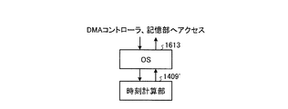
そして、保護リレー1600は、図22−2に示されるように、時刻計算部1409’がCPU1407上で実行されるOS(Operating System)1613上で動作するソフトウェアとして構成される。時刻計算部1409’は、図15のハードウェアとしての時刻計算部1409と同等の機能を実現する。時刻計算部1409’は、OS1613を介して、DMAコントローラ1408や記憶部1412などにアクセスする。
The
例えば、時刻計算部1409’を構成するためのプログラムは、記憶部1412に対して予め記憶される。保護リレー1600の起動に伴い、CPU1407は、記憶部1412からプログラムを読み込んで実行することにより、各モジュールが図示されないRAM上に展開され、時刻計算部1409’がRAM上に構成される。
For example, a program for configuring the
このように、保護リレー1600が有する一部の機能をCPU1407上で動作するソフトウェアとして実装することで、保護リレー1600の回路規模を削減することができる。さらに、本第2の実施形態の第2の変形例による保護リレー1600において、上述の第2の実施形態の第1の変形例による保護リレー1500の如く、通信インタフェース1402を省略し1の通信インタフェース1401のみを備える構成とすることもできる。
In this way, by implementing some functions of the
(第2の実施形態の第3の変形例)
次に、本第2の実施形態の第3の変形例について説明する。図23−1に例示される保護リレー1700は、図15を用いて説明した第2の実施形態による保護リレー1400における、さらに多くの部分の構成を、CPU1407上で動作するソフトウェアで実現した例である。なお、図23−1および図23−2において、上述の図15、ならびに、図22−1および図22−2と機能が共通する部分には同一の符号を付し、詳細な説明を省略する。
(Third Modification of Second Embodiment)
Next, a third modification of the second embodiment will be described. The
この例では、保護リレー1700は、図23−1に示されるように、ハードウェアとしては通信インターフェイス1401および1402、ネットワーク処理部1403、水晶発振器1404、CPU1407、DMAコントローラ1408、記憶部1412、ならびに、バス1430を備える。CPU1407、DMAコントローラ1408および記憶部1412は、バス1430により互いに通信可能に接続される。
In this example, as shown in FIG. 23-1, the
そして、保護リレー1700は、図23−2に示されるように、時刻計算部1409’、タイムスタンプ補正部1410’およびリレー演算部1411’が、CPU1407上で実行されるOS(Operating System)1613上で動作するソフトウェアとしてそれぞれ構成される。時刻計算部1409’、タイムスタンプ補正部1410’およびリレー演算部1411’は、それぞれ、図15のハードウェアとしての時刻計算部1409、タイムスタンプ補正部1410およびリレー演算部1411と同等の機能を実現する。時刻計算部1409’、タイムスタンプ補正部1410’およびリレー演算部1411’は、OS1613を介して、DMAコントローラ1408や記憶部1412などにアクセスする。
Then, as shown in FIG. 23-2, the
このように、保護リレー1700が有するより多くの部分の機能をCPU1407上で動作するソフトウェアとして実装することで、保護リレー1700の回路規模を大幅に削減することができる。例えば、本第2の実施形態の第3の変形例によれば、上述した第2の実施形態の第2の変形例よりも、さらに回路規模を削減することが可能である。さらに、本第2の実施形態の第3の変形例による保護リレー1700において、上述の第2の実施形態の第1の変形例による保護リレー1500の如く、通信インタフェース1402を省略し1の通信インタフェース1401のみを備える構成とすることもできる。
As described above, by implementing more functions of the
第2の実施形態の第2および第3の変形例による保護リレー1600または1700で実行されるプログラムは、例えば記憶部1412に予め記憶されて提供される。これに限らず、当該プログラムを、ネットワークを介して保護リレー1600または1700に対して提供してもよい。この場合、例えば、プログラムを含むフレームが通信インタフェース1401または1402に受信され、ネットワーク処理部1403およびDMAコントローラ1408を介して記憶部1412に記憶される。
The program executed by the
これに限らず、当該プログラムを、インストール可能な形式または実行可能な形式のファイルでCD(Compact Disk)、フレキシブルディスク(FD)、DVD(Digital Versatile Disk)などのコンピュータで読み取り可能な記録媒体に記録されて提供されるようにもできる。この場合、バス1430に対して記録媒体を読み取り可能なドライブ装置を接続する。そして、プログラムが記録された記録媒体をこのドライブ装置に装着し、記録媒体からプログラムを読み出して記憶部1412に記憶させる。
Not limited to this, the program is recorded in a computer-readable recording medium such as a CD (Compact Disk), a flexible disk (FD), and a DVD (Digital Versatile Disk) in a file in an installable or executable format. Can also be provided. In this case, a drive device that can read the recording medium is connected to the
各実施形態および各実施形態の各変形例は、変電所における保護システム以外のシステムにも適用できる。例えば、工場、自動車、航空機、列車、船、発電所などにおけるオートメーションシステム、センサネットワーク、またはアドホックネットワークにおいて、複数個所における計測装置が計測したそれぞれの物理量を用いて外部の装置を制御する制御装置が利用されている。そこで、制御装置は各実施形態における保護リレーと同様の動作を行い、計測装置は各実施形態における計測装置と同様の動作を行うことで、信頼性が高くネットワークの柔軟性を兼ね備えた同期システムを構築可能である。なお、制御装置は遮断指令の代わりに外部の装置を制御する制御量を記述したメッセージを外部の装置へ送信してもよい。 Each embodiment and each modification of each embodiment can be applied to systems other than the protection system in a substation. For example, in an automation system, a sensor network, or an ad hoc network in a factory, an automobile, an aircraft, a train, a ship, a power plant, etc., a control device that controls an external device using each physical quantity measured by a measurement device at a plurality of locations. It's being used. Therefore, the control device performs the same operation as the protection relay in each embodiment, and the measurement device performs the same operation as the measurement device in each embodiment, thereby providing a synchronous system that has high reliability and network flexibility. It can be constructed. The control device may transmit a message describing a control amount for controlling the external device to the external device instead of the cutoff command.
(公知例との比較)
各実施形態による計測装置は、物理量の送信先である保護リレーや母線保護リレーと1対1で接続する必要がない。そのため、変電所において長距離で大量のケーブルを敷設する必要が無いと共に、変電所の要件に応じて柔軟なネットワークを構成可能である。
(Comparison with known examples)
The measuring device according to each embodiment does not need to be connected one-to-one with a protection relay or a bus protection relay that is a physical quantity transmission destination. Therefore, it is not necessary to lay a large amount of cables over a long distance in the substation, and a flexible network can be configured according to the requirements of the substation.
これに対し、公知例である特許文献1および非特許文献1は、ディジタルネットワークを活用して変電所における大量のケーブルを削減する保護システムを開示している。何れの保護システムにおいても、電力線近くに設置される計測装置が複数のアナログケーブルで入力された物理量をディジタル化して1本ケーブルを介して保護リレーへ送信する。これら特許文献1および非特許文献1には、複数の計測装置が物理量の計測タイミングを同期する方法を開示している。
In contrast,
しかしながら、特許文献1および非特許文献1の何方の方法も、ネットワーク構成の柔軟性と障害波及の防止を兼ね備えていない。例えば、非特許文献1は、イーサネット(登録商標)を用いて構成した変電所における系統保護システムを開示している。このシステムは、複数の保護リレーおよび計測装置をイーサネット(登録商標)を用いてリング状に接続する。各機器は、一方に隣接して接続される機器から受信したデータを、他方に隣接して接続される機器へと転送する。非特許文献1が開示するシステムは、ディジタルネットワークとしてイーサネット(登録商標)を利用するため、機器の転送時間が転送のたびに異なる。
However, none of the methods disclosed in
そこで、非特許文献1のシステムは、時刻同期プロトコルIEEE1588を利用して、イーサネット(登録商標)で構築されたネットワークでも高精度に伝送遅延を測定可能としている。すなわち、非特許文献1が開示するシステムでは、グランドマスタクロックと呼ばれる時刻サーバが時刻を配信し、複数の装置が自身の時刻をグランドマスタクロックの時刻に同期することで、複数の装置同士が時刻を同期する。
Therefore, the system of
しかしながら、非特許文献1に記される系統保護システムにおいて、グランドマスタクロックに異常が起きると、系統保護システム内の全ての保護リレーが電力系統を保護できなくなる。
However, in the system protection system described in
一般に、系統保護システム内における個々の保護リレーは、電力系統内の異なるエリアを監視する。例え、1箇所のエリアを管轄する保護リレーや計測装置に異常が起きても、他のエリアを管轄する機器は関係なく正常に動作することが望まれる。 In general, individual protection relays within the grid protection system monitor different areas within the power system. For example, even if an abnormality occurs in a protective relay or a measuring device that has jurisdiction over one area, it is desirable that devices that have jurisdiction over other areas operate normally.
これに対し、非特許文献1が開示する系統保護システムでは、全ての機器がグランドマスタクロックの信頼性に影響を受けるため、系統保護システムの信頼性が著しく低下するおそれがある。グランドマスタクロックを冗長化しても、グランドマスタクロックの障害が系統保護システム全体に波及する可能性がある状況に変わりない。これは、システムがリング型ネットワークではなくスター型のネットワークで構成された場合でも、同様の問題が存在する。
On the other hand, in the system protection system disclosed in
上述した第1の実施形態および第1の実施形態の各変形例では、同じ保護リレーに物理量データフレームを送信する複数の計測装置は、同じ保護リレーの時刻を基にして物理量の計測タイミングを決定するため、同じタイミングで物理量を計測することができる。そして、たとえ一台の保護リレーが故障しても、他の保護リレーに送信するための物理量の計測タイミングに影響しない。また、上述した第2の実施形態および第2の実施形態の各変形例では、保護リレーは、異なる計測装置から送信された物理量の計測時刻を、自身の時刻に変換しているため、異なる計測装置それぞれの計測タイミングの関係を把握することができ、各計測装置の物理量の値による時系列データを比較することで、過電流等の異常の有無を検証できる。そして、たとえ一台の保護リレーが故障しても、他の保護リレーにおける時刻の変換処理に影響しない。そのため、各実施形態および各実施形態の各変形例は、非特許文献1において起こり得る、広範囲への障害波及を防ぐことができる。
In the first embodiment and the modifications of the first embodiment described above, a plurality of measuring devices that transmit physical quantity data frames to the same protection relay determine the measurement timing of the physical quantity based on the time of the same protection relay. Therefore, the physical quantity can be measured at the same timing. And even if one protection relay fails, it does not affect the measurement timing of the physical quantity for transmission to other protection relays. Further, in the second embodiment and the modifications of the second embodiment described above, the protection relay converts the measurement time of the physical quantity transmitted from the different measurement device into its own time, and thus different measurement. The relationship between the measurement timings of the respective devices can be grasped, and the presence / absence of an abnormality such as an overcurrent can be verified by comparing time series data based on the physical quantity values of the respective measurement devices. And even if one protection relay fails, it does not affect the time conversion process in other protection relays. Therefore, each embodiment and each modified example of each embodiment can prevent a failure spreading to a wide range that can occur in
また、特許文献1には、1組の保護リレーと計測装置を1本の光ファイバケーブルで接続する保護システムが開示されている。特許文献1が開示するシステムは、保護リレーと計測装置との間に転送装置が存在しないため、伝送遅延を略一定に維持可能である。特許文献1が開示する計測装置は、保護リレーからクロック信号を受信したタイミングで、ディジタル化した物理量を保護リレーへ送信する。保護リレーは、複数の計測装置へクロック信号を送信するタイミングを合わせることで、複数の地点の物理量の測定タイミングを同期する。
しかしながら、特許文献1が開示するシステムは、通信する1台の保護リレーと1台の計測装置につき1本のケーブルを必要とする。特許文献1が開示するシステムは、伝送遅延を一定に保つためリングやスター型といったネットワークを構成できないため、大量のケーブルを必要とする。
However, the system disclosed in
これに対して、各実施形態による計測装置は、既に説明したように、物理量の送信先である保護リレーや母線保護リレーと1対1で接続する必要がない。そのため、変電所において長距離で大量のケーブルを敷設する必要が無いと共に、変電所の要件に応じて柔軟なネットワークを構成可能である。 On the other hand, as already described, the measuring device according to each embodiment does not need to be connected one-to-one with the protection relay or bus protection relay that is the transmission destination of the physical quantity. Therefore, it is not necessary to lay a large amount of cables over a long distance in the substation, and a flexible network can be configured according to the requirements of the substation.
以上説明したように、第1および第2の実施形態、ならびに、各実施形態それぞれの各変形例は、時刻同期システムの高信頼性とネットワーク構成の柔軟性を兼ね備えた保護システムを構成することができる。 As described above, the first and second embodiments and each modification of each embodiment may constitute a protection system that combines the high reliability of the time synchronization system and the flexibility of the network configuration. it can.
なお、本発明は、上記各実施形態および各実施形態の各変形例そのままに限定されるものではなく、実施段階ではその要旨を逸脱しない範囲で構成要素を変形して具体化することができる。また、上記各実施形態および各実施形態の各変形例に開示されている複数の構成要素の適宜な組み合わせにより、種々の発明を形成することができる。例えば、実施形態に示される全構成要素からいくつかの構成要素を削除してもよい。さらに、異なる実施形態にわたる構成要素を適宜組み合わせても良い。 The present invention is not limited to the above-described embodiments and modifications of the embodiments as they are, and can be embodied by modifying the constituent elements without departing from the scope of the invention in the implementation stage. Further, various inventions can be formed by appropriately combining a plurality of constituent elements disclosed in each of the above embodiments and each modification of each embodiment. For example, some components may be deleted from all the components shown in the embodiment. Furthermore, the constituent elements over different embodiments may be appropriately combined.
101〜103,1400,1400’,1500,1600,1700 保護リレー
104〜109,500,600,700,800 計測装置
130 母線保護リレー
116〜118 送電線
501,502,1401,1402 通信インタフェース
503,1403 ネットワーク処理部
505,1406 MUX
506,1405 DEMUX
512,1407 CPU
513 時刻計算部
514,1412 記憶部
515,1404 水晶発振器
517 タイミング調整部
518 フレーム生成部
1410 タイムスタンプ補正部
1411 リレー演算部
2209 時刻提供部
101 to 103, 1400, 1400 ′, 1500, 1600, 1700
506, 1405 DEMUX
512, 1407 CPU
513
Claims (4)
クロックを発生し該クロックを計数したカウント値を出力するクロック出力部と、
時刻情報を含む第1のメッセージを受信する受信部と、
前記第1のメッセージに含まれる前記時刻情報と、該第1のメッセージを受信した際に前記クロック出力部から出力された前記カウント値とに基づいて、前記物理量を前記入力部から取得するタイミングを調整する調整部と、
前記調整部で調整された前記タイミングで前記物理量の値を取得し、取得した前記物理量の値を含む第2のメッセージを生成する生成部と、
前記第2のメッセージを前記第1のメッセージの送信元の機器に送信する送信部と
を備え、
前記調整部は、
複数の前記機器に対する前記タイミングをそれぞれ求め、求められた該タイミングのうち最も時刻の早いタイミングを次に前記物理量を取得するタイミングとする
ことを特徴とする計測装置。 An input unit for inputting a physical quantity;
A clock output unit for generating a clock and outputting a count value obtained by counting the clock;
A receiving unit for receiving a first message including time information;
Timing for acquiring the physical quantity from the input unit based on the time information included in the first message and the count value output from the clock output unit when the first message is received. An adjustment section to be adjusted;
A generation unit that acquires the value of the physical quantity at the timing adjusted by the adjustment unit, and generates a second message including the acquired value of the physical quantity;
A transmission unit that transmits the second message to a device that is a transmission source of the first message ,
The adjustment unit is
The measurement apparatus characterized in that the timing for each of the plurality of devices is obtained, and the earliest time among the obtained timings is set as the next timing for acquiring the physical quantity .
前記タイミングが示す間隔が、前記機器から送信された前記第1のメッセージに含まれる前記時刻情報が示す時刻に換算して略一定間隔になるように調整する
ことを特徴とする請求項1に記載の計測装置。 Before Sulfur butterfly-save is,
Interval indicated by the timing, according to claim 1, characterized in that adjusted to be approximately constant interval in terms of time indicated by the time information included in the first message sent from the device Measuring device.
複数の機器それぞれに対する前記タイミングの間隔が予め決められた時間よりも短い場合に、該複数の機器それぞれに対するタイミングのうち何れか1を、前記物理量の値を取得するタイミングとする
ことを特徴とする請求項1に記載の計測装置。 Before Sulfur butterfly-save is,
When the timing interval for each of a plurality of devices is shorter than a predetermined time, one of the timings for each of the plurality of devices is set as a timing for acquiring the value of the physical quantity. The measuring device according to claim 1.
前記計測方法は、
物理量を入力する入力ステップと、
クロックを発生し該クロックを計数したカウント値を出力するクロック出力ステップと、
時刻情報を含む第1のメッセージを受信する受信ステップと、
前記第1のメッセージに含まれる前記時刻情報と、該第1のメッセージを受信した際に前記クロック出力部から出力された前記カウント値とに基づいて、前記物理量を前記入力ステップにより取得するタイミングを調整する調整ステップと、
前記調整ステップで調整された前記タイミングで前記物理量の値を取得し、取得した前記物理量の値を含む第2のメッセージを生成する生成ステップと、
前記第2のメッセージを前記第1のメッセージの送信元の機器に送信する送信ステップと
を備え、
前記調整ステップは、
複数の前記機器に対する前記タイミングをそれぞれ求め、求められた該タイミングのうち最も時刻の早いタイミングを次に前記物理量を取得するタイミングとするプログラム。 A program for causing a computer to execute a measurement method,
The measurement method is:
An input step for entering a physical quantity;
A clock output step for generating a clock and outputting a count value obtained by counting the clock;
A receiving step for receiving a first message including time information;
Based on the time information included in the first message and the count value output from the clock output unit when the first message is received, timing for acquiring the physical quantity by the input step Adjustment steps to adjust;
Generating a value of the physical quantity at the timing adjusted in the adjustment step, and generating a second message including the acquired value of the physical quantity;
A transmission step of transmitting the second message to a transmission source device of the first message,
The adjustment step includes
A program for obtaining the timings for a plurality of the devices, and setting the earliest time among the obtained timings as the timing for obtaining the physical quantity next .
Priority Applications (2)
| Application Number | Priority Date | Filing Date | Title |
|---|---|---|---|
| JP2010207379A JP5259663B2 (en) | 2010-09-15 | 2010-09-15 | Measuring device and program |
| US13/231,008 US9476922B2 (en) | 2010-09-15 | 2011-09-13 | Measuring device, protection relay, and program product |
Applications Claiming Priority (1)
| Application Number | Priority Date | Filing Date | Title |
|---|---|---|---|
| JP2010207379A JP5259663B2 (en) | 2010-09-15 | 2010-09-15 | Measuring device and program |
Publications (2)
| Publication Number | Publication Date |
|---|---|
| JP2012065445A JP2012065445A (en) | 2012-03-29 |
| JP5259663B2 true JP5259663B2 (en) | 2013-08-07 |
Family
ID=45807532
Family Applications (1)
| Application Number | Title | Priority Date | Filing Date |
|---|---|---|---|
| JP2010207379A Expired - Fee Related JP5259663B2 (en) | 2010-09-15 | 2010-09-15 | Measuring device and program |
Country Status (2)
| Country | Link |
|---|---|
| US (1) | US9476922B2 (en) |
| JP (1) | JP5259663B2 (en) |
Families Citing this family (12)
| Publication number | Priority date | Publication date | Assignee | Title |
|---|---|---|---|---|
| WO2013143592A1 (en) * | 2012-03-29 | 2013-10-03 | Siemens Aktiengesellschaft | Method and apparatus for redundantly transmitting time-critical data |
| US9316671B2 (en) * | 2012-10-03 | 2016-04-19 | Abb Technology Ltd | Method for sensing a fault in a power system based on travelling wave currents |
| JP6192995B2 (en) * | 2013-06-04 | 2017-09-06 | 株式会社東芝 | COMMUNICATION DEVICE, COMMUNICATION SYSTEM, COMMUNICATION METHOD, AND COMPUTER PROGRAM |
| DE102014112901A1 (en) * | 2014-09-08 | 2016-03-10 | Phoenix Contact Gmbh & Co. Kg | Communication device, communication system and method for the synchronized transmission of telegrams |
| WO2017033416A1 (en) * | 2015-08-27 | 2017-03-02 | 日本電気株式会社 | Relay device, communication system, and fault detection method |
| FI3379272T3 (en) * | 2017-03-21 | 2025-06-25 | Danfoss As | Method and system for detecting the occurrence and timing of events in an electric power system |
| US10436825B2 (en) | 2017-07-26 | 2019-10-08 | Panoramic Power Ltd. | System and method for transmission of time stamps of current samples sampled by a self-powered power sensor |
| MX2020000895A (en) | 2017-07-26 | 2020-07-22 | Panoramic Power Ltd | Timing synchronization of self-powered power sensors and a central controller collecting samples therefrom. |
| WO2019022796A1 (en) * | 2017-07-26 | 2019-01-31 | Panoramic Power Ltd. | System and method of timing synchronization of a self-powered power sensor |
| CN110299697B (en) * | 2018-03-23 | 2021-08-06 | 中国石油化工股份有限公司 | Method and system for realizing line current differential protection |
| JP6501993B1 (en) * | 2018-06-06 | 2019-04-17 | 三菱電機株式会社 | Process bus application protection system and intelligent electronic device |
| CN114221730B (en) * | 2020-09-04 | 2026-01-09 | 华为技术有限公司 | Message processing methods, apparatus, equipment, systems and storage media |
Family Cites Families (8)
| Publication number | Priority date | Publication date | Assignee | Title |
|---|---|---|---|---|
| US4725914A (en) * | 1986-12-16 | 1988-02-16 | Westinghouse Electric Corp. | Protective relay system for performing selective-pole trip determination |
| ES2320310T3 (en) * | 2000-03-10 | 2009-05-21 | Abb Schweiz Ag | METHOD AND DEVICE FOR EVALUATING THE STABILITY OF AN ELECTRICAL TRANSMISSION NETWORK. |
| JP3907998B2 (en) * | 2001-02-09 | 2007-04-18 | 株式会社東芝 | Substation protection control system |
| JP4214807B2 (en) * | 2003-03-26 | 2009-01-28 | パナソニック株式会社 | Copyright protection system, transmission apparatus, copyright protection method, and recording medium |
| US20060259255A1 (en) * | 2005-04-05 | 2006-11-16 | Anderson James C | Method of visualizing power system quantities using a configurable software visualization tool |
| US7693607B2 (en) | 2006-09-07 | 2010-04-06 | General Electric Company | Protection and control system for electric power networks with signal and command interfaces at the primary equipment |
| TWI373709B (en) * | 2008-06-30 | 2012-10-01 | Acer Inc | Power management device and method thereof for saving power consumption of electronic device |
| US20100192001A1 (en) * | 2009-01-29 | 2010-07-29 | Itron, Inc. | Device time adjustment for accurate data exchange |
-
2010
- 2010-09-15 JP JP2010207379A patent/JP5259663B2/en not_active Expired - Fee Related
-
2011
- 2011-09-13 US US13/231,008 patent/US9476922B2/en not_active Expired - Fee Related
Also Published As
| Publication number | Publication date |
|---|---|
| US20120065907A1 (en) | 2012-03-15 |
| JP2012065445A (en) | 2012-03-29 |
| US9476922B2 (en) | 2016-10-25 |
Similar Documents
| Publication | Publication Date | Title |
|---|---|---|
| JP5259663B2 (en) | Measuring device and program | |
| US10859611B2 (en) | Measuring and mitigating channel delay in remote data acquisition | |
| RU2567379C1 (en) | Data transmission over packet switched network | |
| US7111195B2 (en) | Method and system for external clock to obtain multiple synchronized redundant computers | |
| JP5020421B1 (en) | Protection control device | |
| JP6365220B2 (en) | Protection relay system and sampling synchronous monitoring method of protection relay system | |
| JP5501909B2 (en) | Protection relay | |
| JP5944177B2 (en) | Protective relay device and protective relay system | |
| KR102490727B1 (en) | Apparatus for generating time synchronization signal linked to master clock, System for monitoring protection control automatically, and Method thereof | |
| JP6654498B2 (en) | Digital protection relay and digital protection relay system | |
| US20230077975A1 (en) | Time synchronization between ieds of different substations | |
| JP7617757B2 (en) | Surveillance system and method | |
| JP6116841B2 (en) | Protection control device system and current differential protection relay device | |
| JPWO2015001641A1 (en) | Protection relay device | |
| Crites et al. | Techniques for Time Synchronization and Significance in Industrial Facilities | |
| JP6349461B2 (en) | Digital protection control device and power system protection method | |
| JP7511538B2 (en) | Protection Relay System | |
| Matilla et al. | ALBA timing system—a known architecture with fast interlock system upgrade | |
| RU2425437C1 (en) | Method and protective device to compute electric network as route switches in long-distance network | |
| JP6867021B2 (en) | Overload detector, power transmission control device, overload detection method, and program | |
| Gessler et al. | A pico-second stable and drift compensated high-precision and low-jitter clock and trigger distribution system for the european xfel project | |
| CN121261862A (en) | Transmission delay accurate measurement synchronization method and related device for distribution network differential protection | |
| Jesus et al. | Feeder differential protection in hybrid mode: Scheme performance with mix of− 9-2le sampled values and analogue inputs | |
| JPH07255127A (en) | Equipment for selecting/disconnecting load |
Legal Events
| Date | Code | Title | Description |
|---|---|---|---|
| A977 | Report on retrieval |
Free format text: JAPANESE INTERMEDIATE CODE: A971007 Effective date: 20120712 |
|
| A131 | Notification of reasons for refusal |
Free format text: JAPANESE INTERMEDIATE CODE: A131 Effective date: 20120814 |
|
| A521 | Request for written amendment filed |
Free format text: JAPANESE INTERMEDIATE CODE: A523 Effective date: 20121012 |
|
| TRDD | Decision of grant or rejection written | ||
| A01 | Written decision to grant a patent or to grant a registration (utility model) |
Free format text: JAPANESE INTERMEDIATE CODE: A01 Effective date: 20130402 |
|
| A61 | First payment of annual fees (during grant procedure) |
Free format text: JAPANESE INTERMEDIATE CODE: A61 Effective date: 20130424 |
|
| FPAY | Renewal fee payment (event date is renewal date of database) |
Free format text: PAYMENT UNTIL: 20160502 Year of fee payment: 3 |
|
| R151 | Written notification of patent or utility model registration |
Ref document number: 5259663 Country of ref document: JP Free format text: JAPANESE INTERMEDIATE CODE: R151 |
|
| LAPS | Cancellation because of no payment of annual fees |