JP5259662B2 - Electrode assembly and secondary battery including the same - Google Patents
Electrode assembly and secondary battery including the same Download PDFInfo
- Publication number
- JP5259662B2 JP5259662B2 JP2010206575A JP2010206575A JP5259662B2 JP 5259662 B2 JP5259662 B2 JP 5259662B2 JP 2010206575 A JP2010206575 A JP 2010206575A JP 2010206575 A JP2010206575 A JP 2010206575A JP 5259662 B2 JP5259662 B2 JP 5259662B2
- Authority
- JP
- Japan
- Prior art keywords
- electrode
- active material
- material layer
- electrode active
- current collector
- Prior art date
- Legal status (The legal status is an assumption and is not a legal conclusion. Google has not performed a legal analysis and makes no representation as to the accuracy of the status listed.)
- Active
Links
Images


Classifications
-
- H—ELECTRICITY
- H01—ELECTRIC ELEMENTS
- H01M—PROCESSES OR MEANS, e.g. BATTERIES, FOR THE DIRECT CONVERSION OF CHEMICAL ENERGY INTO ELECTRICAL ENERGY
- H01M10/00—Secondary cells; Manufacture thereof
- H01M10/05—Accumulators with non-aqueous electrolyte
- H01M10/052—Li-accumulators
-
- H—ELECTRICITY
- H01—ELECTRIC ELEMENTS
- H01M—PROCESSES OR MEANS, e.g. BATTERIES, FOR THE DIRECT CONVERSION OF CHEMICAL ENERGY INTO ELECTRICAL ENERGY
- H01M10/00—Secondary cells; Manufacture thereof
- H01M10/05—Accumulators with non-aqueous electrolyte
- H01M10/052—Li-accumulators
- H01M10/0525—Rocking-chair batteries, i.e. batteries with lithium insertion or intercalation in both electrodes; Lithium-ion batteries
-
- H—ELECTRICITY
- H01—ELECTRIC ELEMENTS
- H01M—PROCESSES OR MEANS, e.g. BATTERIES, FOR THE DIRECT CONVERSION OF CHEMICAL ENERGY INTO ELECTRICAL ENERGY
- H01M10/00—Secondary cells; Manufacture thereof
- H01M10/05—Accumulators with non-aqueous electrolyte
- H01M10/058—Construction or manufacture
- H01M10/0585—Construction or manufacture of accumulators having only flat construction elements, i.e. flat positive electrodes, flat negative electrodes and flat separators
-
- H—ELECTRICITY
- H01—ELECTRIC ELEMENTS
- H01M—PROCESSES OR MEANS, e.g. BATTERIES, FOR THE DIRECT CONVERSION OF CHEMICAL ENERGY INTO ELECTRICAL ENERGY
- H01M10/00—Secondary cells; Manufacture thereof
- H01M10/42—Methods or arrangements for servicing or maintenance of secondary cells or secondary half-cells
- H01M2010/4292—Aspects relating to capacity ratio of electrodes/electrolyte or anode/cathode
-
- H—ELECTRICITY
- H01—ELECTRIC ELEMENTS
- H01M—PROCESSES OR MEANS, e.g. BATTERIES, FOR THE DIRECT CONVERSION OF CHEMICAL ENERGY INTO ELECTRICAL ENERGY
- H01M4/00—Electrodes
- H01M4/02—Electrodes composed of, or comprising, active material
- H01M4/13—Electrodes for accumulators with non-aqueous electrolyte, e.g. for lithium-accumulators; Processes of manufacture thereof
- H01M4/131—Electrodes based on mixed oxides or hydroxides, or on mixtures of oxides or hydroxides, e.g. LiCoOx
-
- H—ELECTRICITY
- H01—ELECTRIC ELEMENTS
- H01M—PROCESSES OR MEANS, e.g. BATTERIES, FOR THE DIRECT CONVERSION OF CHEMICAL ENERGY INTO ELECTRICAL ENERGY
- H01M4/00—Electrodes
- H01M4/02—Electrodes composed of, or comprising, active material
- H01M4/36—Selection of substances as active materials, active masses, active liquids
- H01M4/48—Selection of substances as active materials, active masses, active liquids of inorganic oxides or hydroxides
- H01M4/485—Selection of substances as active materials, active masses, active liquids of inorganic oxides or hydroxides of mixed oxides or hydroxides for inserting or intercalating light metals, e.g. LiTi2O4 or LiTi2OxFy
-
- Y—GENERAL TAGGING OF NEW TECHNOLOGICAL DEVELOPMENTS; GENERAL TAGGING OF CROSS-SECTIONAL TECHNOLOGIES SPANNING OVER SEVERAL SECTIONS OF THE IPC; TECHNICAL SUBJECTS COVERED BY FORMER USPC CROSS-REFERENCE ART COLLECTIONS [XRACs] AND DIGESTS
- Y02—TECHNOLOGIES OR APPLICATIONS FOR MITIGATION OR ADAPTATION AGAINST CLIMATE CHANGE
- Y02E—REDUCTION OF GREENHOUSE GAS [GHG] EMISSIONS, RELATED TO ENERGY GENERATION, TRANSMISSION OR DISTRIBUTION
- Y02E60/00—Enabling technologies; Technologies with a potential or indirect contribution to GHG emissions mitigation
- Y02E60/10—Energy storage using batteries
-
- Y—GENERAL TAGGING OF NEW TECHNOLOGICAL DEVELOPMENTS; GENERAL TAGGING OF CROSS-SECTIONAL TECHNOLOGIES SPANNING OVER SEVERAL SECTIONS OF THE IPC; TECHNICAL SUBJECTS COVERED BY FORMER USPC CROSS-REFERENCE ART COLLECTIONS [XRACs] AND DIGESTS
- Y02—TECHNOLOGIES OR APPLICATIONS FOR MITIGATION OR ADAPTATION AGAINST CLIMATE CHANGE
- Y02P—CLIMATE CHANGE MITIGATION TECHNOLOGIES IN THE PRODUCTION OR PROCESSING OF GOODS
- Y02P70/00—Climate change mitigation technologies in the production process for final industrial or consumer products
- Y02P70/50—Manufacturing or production processes characterised by the final manufactured product
Landscapes
- Engineering & Computer Science (AREA)
- Chemical & Material Sciences (AREA)
- Manufacturing & Machinery (AREA)
- Chemical Kinetics & Catalysis (AREA)
- Electrochemistry (AREA)
- General Chemical & Material Sciences (AREA)
- Materials Engineering (AREA)
- Secondary Cells (AREA)
- Battery Electrode And Active Subsutance (AREA)
Description
本発明は、電極組立体及びこれを含む二次電池に関する。 The present invention relates to an electrode assembly and a secondary battery including the same.
近年、電子、通信、コンピュータ産業の急速な発展に伴って、携帯用電子機器の普及が増加している。携帯用電子機器の電源としては、再充電が可能な二次電池が主に使用されている。かかる二次電池は一般的に、正極活物質を含む正極と、負極活物質を含む負極と、正極と負極の間に介在され、正極と負極を絶縁するセパレーターとを含む電極組立体を含んでいる。 In recent years, with the rapid development of the electronic, communication, and computer industries, the spread of portable electronic devices has increased. As power sources for portable electronic devices, rechargeable secondary batteries are mainly used. Such secondary batteries generally include an electrode assembly including a positive electrode including a positive electrode active material, a negative electrode including a negative electrode active material, and a separator interposed between the positive electrode and the negative electrode to insulate the positive electrode from the negative electrode. Yes.
二次電池において重要な特性の一つとしては、高温保存時のスウェリング(swelling)の制御が挙げられる。特に、負極活物質としてLTO(Lithium Titanium Oxide)を含む場合、放電状態(SOC(state of charge)0%)でのスウェリングが、充電状態(SOC100%)でのスウェリングに比べてより大きく現われる。スウェリングが発生する場合、二次電池の密閉力が弱くなって、電解液の漏出または水分の浸透によって二次電池の性能が低下する。よって、二次電池におけるスウェリングの制御は、必ず考慮されるべきである。
One of the important characteristics of the secondary battery is control of swelling during high-temperature storage. In particular, when LTO (Lithium Titanium Oxide) is included as a negative electrode active material, swelling in a discharged state (SOC (state of charge) 0%) appears more significantly than swelling in a charged state (
本発明の目的は、二次電池に適用してスウェリングを防止することができ、特に負極活物質としてLTO(Lithium Titanium Oxide)を含む場合にも、放電状態(SOC0%)でのスウェリング防止効果が高い電極組立体を提供することにある。 The object of the present invention can be applied to a secondary battery to prevent swelling. In particular, even when LTO (Lithium Titanium Oxide) is included as a negative electrode active material, the swelling is prevented in a discharged state (SOC 0%). The object is to provide an electrode assembly that is highly effective.
本発明の別の目的は、スウェリングの防止効果が高い二次電池を提供することにある。 Another object of the present invention is to provide a secondary battery having a high anti-swelling effect.
上述の目的を達成するために、本発明の一態様による電極組立体は、第1の電極集電体及び第1の電極集電体の少なくとも一面に形成された第1の電極活物質層を含む第1の電極と、第2の電極集電体及び第2の電極集電体の少なくとも一面に形成された第2の電極活物質層を含む第2の電極と、第1の電極と第2の電極の間に位置するセパレーターと、を含み、第2の電極活物質層は第1の電極活物質層に対向し、第1の電極活物質層の面積は第2の電極活物質層の面積より大きく、第2の電極活物質層はLTO(Lithium Titanium Oxide)を含むことを特徴とする。 In order to achieve the above object, an electrode assembly according to an aspect of the present invention includes a first electrode current collector and a first electrode active material layer formed on at least one surface of the first electrode current collector. A second electrode including a second electrode active material layer formed on at least one surface of the second electrode current collector and the second electrode current collector, the first electrode, A separator positioned between the two electrodes, the second electrode active material layer facing the first electrode active material layer, and the area of the first electrode active material layer is the second electrode active material layer And the second electrode active material layer contains LTO (Lithium Titanium Oxide).
第1の電極集電体の面積は、第2の電極集電体の面積より大きくてもよい。第2の電極集電体の面積は、第1の電極集電体の面積より大きくてもよい。第1の電極集電体の面積は、第2の電極集電体の面積と実質的に等しくてもよい。 The area of the first electrode current collector may be larger than the area of the second electrode current collector. The area of the second electrode current collector may be larger than the area of the first electrode current collector. The area of the first electrode current collector may be substantially equal to the area of the second electrode current collector.
第1の電極は正極であり、第2の電極は負極であってもよい。 The first electrode may be a positive electrode and the second electrode may be a negative electrode.
第2の電極活物質層に対する第1の電極活物質層の面積比は、1.01〜1.21であってもよい。第2の電極活物質層に対する第1の電極活物質層の面積比は、1.01〜1.10であってもよい。 The area ratio of the first electrode active material layer to the second electrode active material layer may be 1.01 to 1.21. The area ratio of the first electrode active material layer to the second electrode active material layer may be 1.01 to 1.10.
第1の電極活物質層は第2の電極活物質層を覆うように形成されてもよい。 The first electrode active material layer may be formed so as to cover the second electrode active material layer.
第1の電極活物質層の容量(capacity)に対する第2の電極活物質層の容量比は、1.0〜1.5であってもよい。第1の電極活物質層の容量(capacity)に対する第2の電極活物質層の容量比は、1.0〜1.3であってもよい。 The capacity ratio of the second electrode active material layer to the capacity of the first electrode active material layer may be 1.0 to 1.5. The capacity ratio of the second electrode active material layer to the capacity of the first electrode active material layer may be 1.0 to 1.3.
第1の電極活物質層は、第2の電極活物質層に対向する第1の電極集電体の表面及び第1の電極集電体の反対側表面にそれぞれ形成され、第2の電極活物質層は、第1の電極活物質層に対向する第2の電極集電体の表面及び第2の電極集電体の反対側表面にそれぞれ形成されてもよい。 The first electrode active material layer is formed on the surface of the first electrode current collector facing the second electrode active material layer and the opposite surface of the first electrode current collector, respectively. The material layer may be formed on the surface of the second electrode current collector facing the first electrode active material layer and on the opposite surface of the second electrode current collector.
第1の電極活物質層は、第2の電極活物質層に対向する第1の電極集電体の表面のみに形成され、第2の電極活物質層は、第1の電極活物質層に対向する第2の電極集電体の表面のみに形成されてもよい。 The first electrode active material layer is formed only on the surface of the first electrode current collector facing the second electrode active material layer, and the second electrode active material layer is formed on the first electrode active material layer. It may be formed only on the surface of the opposing second electrode current collector.
上述の目的を達成するために、本発明の別の態様による二次電池は、第1の電極集電体及び第1の電極集電体の少なくとも一面に形成された第1の電極活物質層を含む第1の電極と、第2の電極集電体及び第2の電極集電体の少なくとも一面に形成された第2の電極活物質層を含む第2の電極と、第1の電極と第2の電極の間に位置するセパレーターとを含む電極組立体と、電極組立体を収容するケースと、電極組立体の第1の電極及び第2の電極と電気的に接続される保護回路モジュールと、ケースに満たされる電解液とを含み、電極組立体は、第2の電極活物質層が第1の電極活物質層に対向し、第1の電極活物質層の面積は第2の電極活物質層の面積より大きく、第2の電極活物質層はLTO(Lithium Titanium Oxide)を含むことを特徴とする。 In order to achieve the above object, a secondary battery according to another aspect of the present invention includes a first electrode current collector and a first electrode active material layer formed on at least one surface of the first electrode current collector. A second electrode including a second electrode active material layer formed on at least one surface of the second electrode current collector and the second electrode current collector, and the first electrode, An electrode assembly including a separator positioned between the second electrodes, a case accommodating the electrode assembly, and a protection circuit module electrically connected to the first electrode and the second electrode of the electrode assembly And an electrolytic solution filled in the case, the electrode assembly has a second electrode active material layer facing the first electrode active material layer, and the area of the first electrode active material layer is the second electrode The second electrode active material layer is larger than the area of the active material layer, and the second electrode active material layer is LTO (Lithium Titanium Ox). ide).
本発明による電極組立体は、正極活物質層の面積が負極活物質層の面積よりも大きく形成されることによって、二次電池に適用したとき、負極活物質層に含まれた全てのLTO(Lithium Titanium Oxide)が充放電に使用されるようになる。すなわち、全てのLTOは添加剤及び電解液と反応して、負極の表面に皮膜を形成し、それによって、LTOと電解液との追加反応によるガスの発生が抑えられて、二次電池のスウェリングを効果的に防止することができる。 The electrode assembly according to the present invention has an area of the positive electrode active material layer larger than the area of the negative electrode active material layer, so that when applied to a secondary battery, all of the LTOs included in the negative electrode active material layer ( Lithium Titanium Oxide) is used for charging and discharging. That is, all the LTOs react with the additive and the electrolytic solution to form a film on the surface of the negative electrode, thereby suppressing the generation of gas due to the additional reaction between the LTO and the electrolytic solution. Rings can be effectively prevented.
以下、添付の図面を参照して本発明の実施形態を詳細に説明するが、本発明が以下の実施形態によって限定されるものではない。添付の図面において同じ構成には同じ参照番号を使用することにする。 Hereinafter, embodiments of the present invention will be described in detail with reference to the accompanying drawings, but the present invention is not limited to the following embodiments. The same reference numbers are used for the same components in the accompanying drawings.
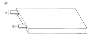
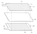
図1は、本発明の一実施形態による電極組立体の斜視図であり、図2は、本発明の一実施形態による電極組立体の分解斜視図であり、図3は、本発明の一実施形態による電極組立体の一部を示す図である。 FIG. 1 is a perspective view of an electrode assembly according to an embodiment of the present invention, FIG. 2 is an exploded perspective view of an electrode assembly according to an embodiment of the present invention, and FIG. 3 is an embodiment of the present invention. It is a figure which shows a part of electrode assembly by a form.
図1〜図3を参照すると、本発明の一実施形態による電極組立体100は、第1の電極、第2の電極及び第1の電極と第2の電極の間に位置するセパレーター130を含む。第1の電極は正極であって第2の電極は負極であってもよいが、第1の電極が負極であって第2の電極が正極であってもよい。以下では、第1の電極が正極110であって、第2の電極が負極120である場合を例に挙げて説明する。
1-3, an
正極110は、正極集電体111と、正極集電体111の少なくとも一面に備えられた正極活物質層112と、正極タブ114とを含む。
The
ここで使用される正極集電体111の厚さは、一般的に10〜500μmである。このような正極集電体111は、その電池に化学的変化を誘発しない且つ高い導電性を有するものであれば特に制限されず、例えば、ステンレススチール、アルミニウム、ニッケル、チタン、焼成炭素、またはアルミニウムやステンレススチールの表面にカーボン、ニッケル、チタン、銀などで表面処理したものなどが使用できる。集電体は、その表面に微細な凹凸を形成して正極活物質の接着力を高めることも可能であり、フィルム、シート、箔、網、多孔質体、発泡体、不織布などの様々な形態が可能である。
The thickness of the positive electrode
正極集電体111上に形成される正極活物質層112は、正極活物質と導電剤及びバインダーを含む通常の正極活物質コーティング組成物を正極集電体111に塗布して形成される。正極活物質層112は、正極集電体111の一面に形成されてもよいが、電池の効率を考慮して正極集電体111の両面に形成されることが好ましい。
The positive electrode
正極活物質としては、当該分野で一般的に使用される物質を適用することが可能であり、例えばLiCoO2を使用してもよい。LiCoO2は、安定した充放電特性、高い電子伝導性、高い安全性及び平坦な放電電圧特性を有する優れた物質である。その他にも、当該分野で一般的に使用されるニッケル‐コバルト‐マンガンが混合された形態のLi[NixCo1‐x‐yMny]O2(ここで、0<x<0.5、0<y<0.5)を使用してもよい。 As the positive electrode active material, it is possible to apply the materials commonly used in the art may be used, such as LiCoO 2. LiCoO 2 is an excellent material having stable charge / discharge characteristics, high electronic conductivity, high safety, and flat discharge voltage characteristics. In addition, Li [Ni x Co 1-xy Mn y ] O 2 in a mixed form of nickel-cobalt-manganese commonly used in the field (where 0 <x <0.5 , 0 <y <0.5) may be used.
導電剤は、その電池に化学的変化を誘発しない且つ導電性を有するものであれば特に制限されるものではない。例えば、カーボンブラック、アセチレンブラック、ケッチェンブラック、チャンネルブラック、ファーネスブラック、ランプブラック、サーマルブラックなどのカーボンブラック;炭素繊維や金属繊維などの導電性繊維;フッ化カーボン、アルミニウム、ニッケル粉末などの金属粉末;酸化亜鉛、チタン酸カリウムなどの導電性ウィスカ;酸化チタンなどの導電性金属酸化物;ポリフェニレン誘導体などの導電性素材などを使用することができる。導電剤は、正極活物質組成物に通常の添加範囲内で添加してもよく、好ましくは1〜10重量%含有されることがよい。 The conductive agent is not particularly limited as long as it does not induce a chemical change in the battery and has conductivity. For example, carbon black such as carbon black, acetylene black, ketjen black, channel black, furnace black, lamp black and thermal black; conductive fiber such as carbon fiber and metal fiber; metal such as carbon fluoride, aluminum and nickel powder Powders; conductive whiskers such as zinc oxide and potassium titanate; conductive metal oxides such as titanium oxide; and conductive materials such as polyphenylene derivatives can be used. The conductive agent may be added to the positive electrode active material composition within a normal addition range, and preferably 1 to 10% by weight.
バインダーは、結合力を付与するために添加するものであって、通常の正極活物質組成物に使用される範囲内で添加してもよい。バインダーとしては、ポリビニルアルコール、カルボキシメチルセルロース、ヒドロキシプロピレンセルロース、ジアセチレンセルロース、ポリ塩化ビニル、ポリビニルピロリドン、ポリテトラフルオロエチレン、ポリフッ化ビニリデン、ポリエチレンまたはポリプロピレンなどを使用してもよいが、これに限定されるものではない。 The binder is added for imparting bonding strength, and may be added within a range used for a normal positive electrode active material composition. As the binder, polyvinyl alcohol, carboxymethyl cellulose, hydroxypropylene cellulose, diacetylene cellulose, polyvinyl chloride, polyvinyl pyrrolidone, polytetrafluoroethylene, polyvinylidene fluoride, polyethylene, or polypropylene may be used, but it is not limited thereto. It is not something.
正極活物質コーティング組成物には、上記の正極活物質、導電剤及びバインダーの他に、必要によって通常の正極活物質コーティング組成物の製造過程で使用される添加剤をさらに添加してもよい。 In addition to the above-described positive electrode active material, conductive agent and binder, additives used in the production process of a normal positive electrode active material coating composition may be further added to the positive electrode active material coating composition as necessary.
正極タブ114は、正極集電体111の一側に形成され、後述するように別途の正極リード端子を介して保護回路モジュールに電気的に接続される。
The
負極120は、負極集電体121と、負極集電体121上に備えられた負極活物質層122と、負極タブ124とを含む。
The
一般的に使用される負極集電体121の厚さは5〜500μmである。このような負極集電体121は、その電池に化学的変化を誘発しない且つ導電性を有するものであれば特に制限されず、例えば、銅、ステンレススチール、アルミニウム、ニッケル、チタン、焼成炭素、銅やステンレススチールの表面にカーボン、ニッケル、チタン、銀などで表面処理したもの、アルミニウム‐カドミウム合金などを使用することができる。また、負極集電体121は、正極集電体111と同様に、表面に微細な凹凸を形成して負極活物質の結合力を強化することもでき、フィルム、シート、箔、網、多孔質体、発泡体、不織布などの様々な形態が使用可能である。
The thickness of the negative electrode
負極集電体121上に形成される負極活物質層122は、負極活物質と導電剤及びバインダーを含む負極活物質コーティング組成物を負極集電体121上に塗布して形成される。負極活物質層122は、負極集電体121の一面に形成されてもよいが、電池の効率を考慮して負極集電体121の両面に形成されることが好ましい。
The negative electrode
負極活物質はLTO(Lithium Titanium Oxide)を含む。 The negative electrode active material includes LTO (Lithium Titanium Oxide).
導電剤とバインダーとしては、当該分野で一般的に使用されるものを適用してもよく、例えば、前述した正極活物質組成物に適用された導電剤とバインダーを使用してもよい。 As the conductive agent and the binder, those commonly used in the field may be applied. For example, the conductive agent and the binder applied to the positive electrode active material composition described above may be used.
負極活物質、導電剤及びバインダーは、通常の使用範囲内で様々な比率で混合してもよい。また、負極活物質コーティング組成物には、上記の負極活物質、導電剤及びバインダーの他に、必要によって通常の負極活物質コーティング組成物の製造過程で使用される添加剤をさらに添加してもよい。 The negative electrode active material, the conductive agent, and the binder may be mixed in various ratios within a normal use range. In addition to the above-described negative electrode active material, conductive agent and binder, the negative electrode active material coating composition may be further added with additives used in the production process of a normal negative electrode active material coating composition as necessary. Good.
負極タブ124は、負極集電体121の一側に形成され、後述するように別途の負極リード端子を介して保護回路モジュールに電気的に接続される。
The
セパレーター130は、正極110と負極120の間に介在されて、その間を絶縁する。セパレーター130は、ポリエチレン(polyethylene)、ポリプロピレン(polypropylene)、ポリフッ化ビニリデン(polyvinylidene fluoride)、ポリエチレンオキシド(polyethylene oxide)、ポリアクリロニトリル(polyacrylonitrile)及びポリフッ化ビニリデンヘキサフルオロプロピレン(polyvinylidene fluoride hexafluoropropylene)からなる群から選択される少なくとも一つを含んでもよい。
The
このとき、セパレーター130は、正極110と負極120との間だけでなく、電極組立体100の最外郭に位置した正極110または負極120の外側に形成されてもよい。この場合、電池の組立ての際に電極組立体100を収容するケースなどから絶縁することができる。
At this time, the
通常、負極活物質としてグラファイト(graphite)を使用する場合、SOC0%に比べてSOC100%でのスウェリングがより大きいと知られており、それによって様々な改善方法が知られている。しかし、負極活物質としてLTOを使用する場合、SOC0%でのスウェリングがSOC100%でのスウェリングに比べてより大きい。LTOを負極活物質として使用する場合に発生するスウェリングを制御するために、本発明では、正極活物質層112の面積を負極活物質層122の面積よりも大きく形成する。このとき、正極集電体111の面積が負極集電体121の面積より大きいか、負極集電体121の面積が正極集電体111の面積より大きいか、または正極集電体111の面積が負極集電体121の面積と実質的に等しくてもよい。
In general, when graphite is used as the negative electrode active material, it is known that the swelling at 100% SOC is larger than 0% SOC, and various improvement methods are known. However, when LTO is used as the negative electrode active material, the swelling at SOC 0% is larger than the swelling at
正極活物質層112の表面は負極活物質層122の表面に対向し、セパレーター130は正極活物質層112の表面と負極活物質層122の表面との間に位置する。ここで、正極活物質層112及び負極活物質層122の面積とは、互いに対向する正極活物質層112及び負極活物質層122の表面面積を意味する。
The surface of the positive electrode
LTOは、既に多くの文献で記述されているように、次の反応式(1)で示すような充放電時の反応式を有する。 LTO has a reaction formula at the time of charge and discharge as shown in the following reaction formula (1) as already described in many documents.
反応式(1)で示すように、放電状態でLTOはスピネル(spinel)形態のLi4Ti5O12として存在する。それによって、負極活物質層122の面積を正極活物質層112の面積より大きく設計する場合、充放電(formation)に使われない状態のLi4Ti5O12が存在するようになる。充放電反応が進行されないLTOが負極に残っている場合、LTOはLiイオンを有しているので、持続的に電解液と反応をしてガスを生成し、それによってスウェリングが大きくなる。反対に、正極活物質層112の面積を負極活物質層122の面積より大きく設計する場合、負極活物質層122の全てのLTOが電池の充放電(formation)に使われる。すなわち、全てのLTOは添加剤及び電解液と反応して負極の表面に被膜を形成し、それによってLTOと電解液との追加反応によるガスの発生が抑えられてスウェリングが防止される。
As shown in the reaction formula (1), LTO exists as Li 4 Ti 5 O 12 in a spinel form in a discharged state. Accordingly, when the area of the negative electrode
このとき、負極活物質層122に対する正極活物質層112の面積比は1.01〜1.21であることが好ましく、特に負極活物質層122に対する正極活物質層112の面積比が1.01〜1.1であることがより好ましい。負極活物質層122に対する正極活物質層112の面積比が1.21を超過する場合、電池の容量が減少する問題点があり、負極活物質層122に対する正極活物質層112の面積比が1.01未満である場合、スウェリングの防止効果が低下する問題点がある。
At this time, the area ratio of the positive electrode
負極活物質層122または正極活物質層112は、正極活物質コーティング組成物または負極活物質コーティング組成物を、ドクターブレードなどのような当該分野で一般的に用いられるコーティング機を用いて上記範囲内の面積比になるように塗布することで、容易に形成することができる。一例として、負極活物質層122と正極活物質層112の面積比の調節は、図2に示すように、集電体上部または下部の無地部の幅を調節することによって行われてもよい。
The negative electrode
正極110と負極120の間にはセパレーター130が介在される。このとき、正極110に備えられた正極活物質層112と負極120に備えられた負極活物質層122は、図3に示すように、セパレーター130を介して互いに対面するように積層される。このとき、スウェリングの防止を最大化するために、負極活物質層122の全面は正極活物質層112に対面するように形成されることが好ましい。すなわち、正極活物質層122の全面が負極活物質層112の全面を覆うように位置することが好ましい。この場合、全てのLTOが充放電反応に使われることによって、スウェリングを効果的に防止することができる。
A
本発明によれば、正極活物質層112に対する負極活物質層122の容量比は、1.0〜1.5であることが好ましく、1.0〜1.3であることがより好ましい。この容量比は、充放電に使われる正極活物質層と負極活物質層だけの容量を考慮したものであって、容量比が1.0〜1.5の範囲内にある場合、スウェリング防止効果の高い特性を示す。ここで、容量は1C‐rate(「C‐rate」アンペアで示される電池の充電または放電電流の比率)で放電したとき、非可逆容量を除いた可逆容量のみを意味する。容量比が1.0〜1.5の範囲内に含まれない場合、電池の全体容量が減少するという欠点がある。
According to the present invention, the capacity ratio of the negative electrode
本発明の一例によれば、電極組立体100は、正極110、セパレーター130及び負極120が繰り返して積層されている積層型(stack type)であることが好ましい。
According to an example of the present invention, the
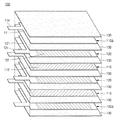
図4は、本発明の別の実施形態による電極組立体の分解斜視図である。 FIG. 4 is an exploded perspective view of an electrode assembly according to another embodiment of the present invention.
図4を参照すると、電極組立体100は、正極110,110a、負極120,120a及びセパレーター130を含む。
Referring to FIG. 4, the
電極組立体100は、正極110、セパレーター130及び負極120が繰り返して積層され、それぞれの構成は前述した図1〜図3を参照して説明しているので、その詳細な説明は省略する。但し、本実施形態では、電極組立体100の最外郭部分に形成される正極110aと負極120aが異なるので、それについて詳細に説明することにする。
In the
電極組立体100の最外郭に位置する正極110a及び負極120aは、その内側表面のみに活物質層が形成され、電極組立体100の最外郭に位置する正極110a及び負極120aを除いた他の正極110及び負極120は、両面に活物質層が形成される。最外郭に位置する負極120aの両面に負極活物質層122が形成される場合、外側表面に形成された負極活物質層122に含まれているLTOが充放電反応に使われず、それによってスウェリングの制御が効果的に行われない可能性がある。しかし、最外郭に位置する負極120aの内側表面のみに負極活物質層122が形成される場合、全てのLTOが充放電に使われるので、スウェリング防止効果が最大化される。
The
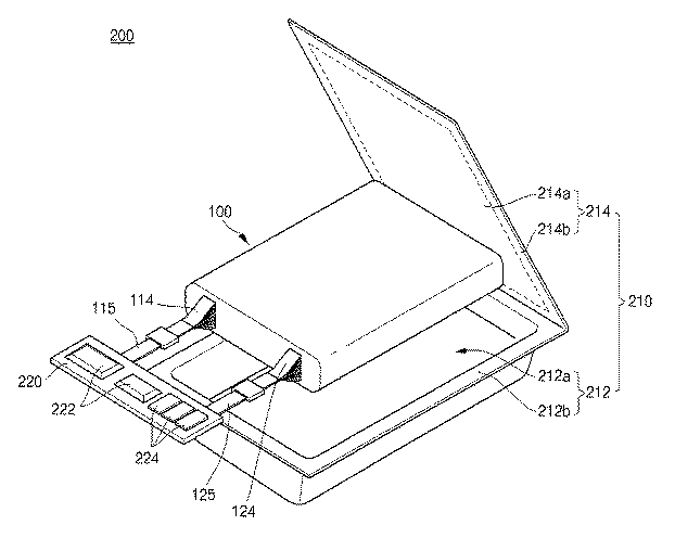
図5は、本発明の一実施形態による電極組立体を含む二次電池を示す斜視図である。 FIG. 5 is a perspective view illustrating a rechargeable battery including an electrode assembly according to an embodiment of the present invention.
図5を参照すると、二次電池200は、電極組立体100と、電極組立体100を収容するケース210と、リード端子115,125を介して電極組立体100と電気的に接続される保護回路モジュール220と、電解液(図示せず)とを含む。ここで、二次電池200はパウチ型であることが好ましい。
Referring to FIG. 5, the
電極組立体100は、少なくとも一面に正極活物質層が備えられた正極と、少なくとも一面にLTO(Lithium Titanium Oxide)を含む負極活物質層が備えられた負極と、正極と負極の間に介在され、正極電極と負極電極の間を絶縁するセパレーターとを含み、正極活物質層の面積が負極活物質層の面積よりも大きく形成される。このような構成を有する電極組立体100は前述した通りであるので、これについての詳細な説明は省略することにする。
The
ケース210は、本体212及びカバー214を備えている。
The
本体212は、電極組立体100を収容する空間である収容部212a及び収容部212aの入口から延びている密封部212bを備えている。
The
カバー214は、本体212の密封部212bの何れの縁部から延びるように形成されてもよい。
The
カバー214は、本体212の収容部212aを覆いながら本体212の密封部212bとの密封によって本体212の収容部212aと対応するカバー領域214a及び本体212の密封部212bと対応する密封部214bを備えている。
The
したがって、二次電池200は、電極組立体100が収容部212aに収容され、本体212の密封部212bとカバー214の密封部214bが熱融着のような方法で接合されることで構成される。
Therefore, the
保護回路モジュール220は、リード端子115,125を介して電極組立体100に電気的に接続されている。リード端子115,125は、電極タブ114,124と電気的に接続されている。保護回路モジュール220は、二次電池100を制御する制御素子222を備えている。保護回路モジュール220は、二次電池100の充放電を制御する役割を果たす。保護回路モジュール220は、二次電池100と外部機器とを接続する外部端子224を備えている。
The
本体の密封が完了すると、電解液を注入する。電解液は、非水性有機溶媒とリチウム塩を含んで当該分野で一般的に用いられるものを適用してもよい。本発明は、これに限定されるものではない。 When sealing of the main body is completed, an electrolytic solution is injected. As the electrolytic solution, a non-aqueous organic solvent and a lithium salt, which are generally used in the art, may be applied. The present invention is not limited to this.
以下、本発明のより好ましい実施例及び比較例を通じて本発明をより詳細に説明する。しかし、下記の実施例は本発明を容易に理解するために例示されたものに過ぎないので、本発明が下記の実施例に限定されるものではない。 Hereinafter, the present invention will be described in more detail through more preferred examples and comparative examples of the present invention. However, since the following examples are merely illustrated for easy understanding of the present invention, the present invention is not limited to the following examples.
<実施例1〜4、比較例1及び2>
正極の製造
活物質としてLiCoO2を使用し、バインダーとしては、PVDF(Polyvinylidene Fluoride)を使用し、導電剤としてはカーボンブラックを使用して、正極活物質コーティング組成物を製造した。このとき、正極活物質コーティング組成物は、活物質:バインダー:導電剤の比率が94:3:3になるようにし、活物質コーティング組成物を混合器(Planetary Despa Mixer)を用いてN‐メチル‐2‐ピロリドンに分散させてスラリー化し、ドクターブレードを用いて厚さ20μmのアルミニウム箔に塗布した後、乾燥させた。このとき、コーティング面積は、下記の表1に示したようにした。その後、ロールプレスでプレスし、真空乾燥(vacuum dryer)設備でコーティング層内の水分を取り除いて正極を製造した。
<Examples 1-4, Comparative Examples 1 and 2>
Production of Positive Electrode A positive electrode active material coating composition was produced using LiCoO 2 as an active material, PVDF (Polyvinylidene Fluoride) as a binder, and carbon black as a conductive agent. At this time, the positive electrode active material coating composition has an active material: binder: conductive agent ratio of 94: 3: 3, and the active material coating composition is mixed with N-methyl using a mixer (Planetary Despa Mixer). The slurry was dispersed in 2-pyrrolidone, applied to an aluminum foil having a thickness of 20 μm using a doctor blade, and then dried. At this time, the coating area was as shown in Table 1 below. Then, it pressed with the roll press and removed the water | moisture content in a coating layer with the vacuum dryer (vacuum dryer) equipment, and manufactured the positive electrode.
負極の製造
活物質としてLTOを使用し、正極と同様にバインダーとしてはPVDFを、導電剤としてはカーボンブラックを使用して負極活物質コーティング組成物を製造し、厚さ15μmの銅箔に塗布したことを除いて、正極の製造と同様に負極を製造した。このとき、コーティング面積は下記の表1に示すようにした。
Production of Negative Electrode Using LTO as an active material, PVDF as a binder and carbon black as a conductive agent as in the positive electrode, a negative electrode active material coating composition was produced and applied to a copper foil having a thickness of 15 μm. Except for this, a negative electrode was produced in the same manner as the positive electrode. At this time, the coating area was as shown in Table 1 below.
二次電池の製造
製造された極板でbi‐cell構造を有するパウチ形の二次電池を製造した。このとき、電解液としては、1.1M濃度のLiPF6が溶解されたエチレンカーボネート(EC)/エチルメチルカーボネート(EMC)(体積比でEC:EMC混合比は30/70)の混合有機溶媒2.7gを使用し、添加剤は使用しなかった。
Manufacture of Secondary Battery A pouch-type secondary battery having a bi-cell structure was manufactured using the manufactured electrode plate. At this time, as the electrolytic solution, a mixed organic solvent 2 of ethylene carbonate (EC) / ethyl methyl carbonate (EMC) in which 1.1 M concentration of LiPF 6 is dissolved (EC: EMC mixing ratio is 30/70 in volume ratio). 0.7 g was used and no additive was used.
製造された電池を60℃で放置した後、10日後に電池の厚さを測定して放置前の厚さと比較した。 The manufactured battery was left at 60 ° C., and after 10 days, the thickness of the battery was measured and compared with the thickness before leaving.
表1に示すように、負極活物質層の面積が正極活物質層の面積に比べて小さい実施例1〜4の場合、負極活物質層の面積が正極活物質層の面積に比べて大きい比較例1及び2の場合より、スウェリング防止効果が高いことを確認できる。さらに、負極活物質層の面積が正極活物質層の面積に比べて小さい実施形態1〜4で、容量比が小さいほどスウェリング防止効果が高いことを確認できる。 As shown in Table 1, in Examples 1 to 4 where the area of the negative electrode active material layer is small compared to the area of the positive electrode active material layer, the comparison of the area of the negative electrode active material layer is larger than the area of the positive electrode active material layer From the cases of Examples 1 and 2, it can be confirmed that the anti-swelling effect is high. Further, in Embodiments 1 to 4 in which the area of the negative electrode active material layer is smaller than the area of the positive electrode active material layer, it can be confirmed that the smaller the capacity ratio, the higher the anti-swelling effect.
以上、本発明は実施形態を参照して説明されているが、これは本発明を容易に理解するために提示されたものであって、本発明がこれに限定されるものではなく、当該分野における通常の知識を有する者であれば、これから他の様々な均等な実施形態が可能であるということを理解するであろう。 The present invention has been described above with reference to the embodiments. However, the present invention has been presented for the purpose of easily understanding the present invention, and the present invention is not limited thereto. Those of ordinary skill in the art will appreciate that various other equivalent embodiments are now possible.
100 電極組立体
110 正極
111 正極集電体
112 正極活物質層
114 正極タブ
115 正極リード端子
120 負極
121 負極集電体
122 負極活物質層
124 負極タブ
125 負極リード端子
130 セパレーター
200 二次電池
100
Claims (16)
第2の電極集電体及び前記第2の電極集電体の少なくとも一面に形成された第2の電極活物質層を含む第2の電極と、
前記第1の電極と前記第2の電極の間に位置するセパレーターと、を含み、
前記第2の電極活物質層は前記第1の電極活物質層に対向し、前記第1の電極活物質層の面積は前記第2の電極活物質層の面積より大きく、前記第2の電極活物質層はLTO(Lithium Titanium Oxide)を含み、
前記第1の電極集電体の面積は、前記第2の電極集電体の面積より大きく、
前記第1の電極活物質層の容量(capacity)に対する前記第2の電極活物質層の容量比は、1.0〜1.5であることを特徴とする電極組立体。 A first electrode including a first electrode current collector and a first electrode active material layer formed on at least one surface of the first electrode current collector;
A second electrode including a second electrode current collector and a second electrode active material layer formed on at least one surface of the second electrode current collector;
A separator located between the first electrode and the second electrode,
The second electrode active material layer faces the first electrode active material layer, and the area of the first electrode active material layer is larger than the area of the second electrode active material layer, and the second electrode The active material layer includes LTO (Lithium Titanium Oxide) ,
The area of the first electrode current collector is larger than the area of the second electrode current collector,
The electrode assembly according to claim 1, wherein a capacity ratio of the second electrode active material layer to a capacity of the first electrode active material layer is 1.0 to 1.5 .
第2の電極集電体及び前記第2の電極集電体の少なくとも一面に形成された第2の電極活物質層を含む第2の電極と、A second electrode including a second electrode current collector and a second electrode active material layer formed on at least one surface of the second electrode current collector;
前記第1の電極と前記第2の電極の間に位置するセパレーターと、を含み、A separator located between the first electrode and the second electrode,
前記第2の電極活物質層は前記第1の電極活物質層に対向し、前記第1の電極活物質層の面積は前記第2の電極活物質層の面積より大きく、前記第2の電極活物質層はLTO(Lithium Titanium Oxide)を含み、The second electrode active material layer faces the first electrode active material layer, and the area of the first electrode active material layer is larger than the area of the second electrode active material layer, and the second electrode The active material layer includes LTO (Lithium Titanium Oxide),
前記第2の電極集電体の面積は、前記第1の電極集電体の面積より大きく、The area of the second electrode current collector is larger than the area of the first electrode current collector,
前記第1の電極活物質層の容量(capacity)に対する前記第2の電極活物質層の容量比は、1.0〜1.5であることを特徴とする電極組立体。The electrode assembly according to claim 1, wherein a capacity ratio of the second electrode active material layer to a capacity of the first electrode active material layer is 1.0 to 1.5.
第2の電極集電体及び前記第2の電極集電体の少なくとも一面に形成された第2の電極活物質層を含む第2の電極と、A second electrode including a second electrode current collector and a second electrode active material layer formed on at least one surface of the second electrode current collector;
前記第1の電極と前記第2の電極の間に位置するセパレーターと、を含み、A separator located between the first electrode and the second electrode,
前記第2の電極活物質層は前記第1の電極活物質層に対向し、前記第1の電極活物質層の面積は前記第2の電極活物質層の面積より大きく、前記第2の電極活物質層はLTO(Lithium Titanium Oxide)を含み、The second electrode active material layer faces the first electrode active material layer, and the area of the first electrode active material layer is larger than the area of the second electrode active material layer, and the second electrode The active material layer includes LTO (Lithium Titanium Oxide),
前記第1の電極集電体の面積は、前記第2の電極集電体の面積と実質的に等しく、The area of the first electrode current collector is substantially equal to the area of the second electrode current collector;
前記第1の電極活物質層の容量(capacity)に対する前記第2の電極活物質層の容量比は、1.0〜1.5であることを特徴とする電極組立体。The electrode assembly according to claim 1, wherein a capacity ratio of the second electrode active material layer to a capacity of the first electrode active material layer is 1.0 to 1.5.
前記電極組立体を収容するケースと、
前記電極組立体の第1の電極及び第2の電極と電気的に接続される保護回路モジュールと、
前記ケースに満たされる電解液とを含み、
前記電極組立体は、前記第2の電極活物質層が前記第1の電極活物質層に対向し、前記第1の電極活物質層の面積は前記第2の電極活物質層の面積より大きく、前記第2の電極活物質層はLTO(Lithium Titanium Oxide)を含み、
前記第1の電極集電体の面積は、前記第2の電極集電体の面積より大きく、
前記第1の電極活物質層の容量(capacity)に対する前記第2の電極活物質層の容量比は、1.0〜1.5であることを特徴とする二次電池。 A first electrode including a first electrode active material layer formed on at least one surface of the first electrode current collector and the first electrode current collector; a second electrode current collector; and the second electrode current collector. An electrode assembly including a second electrode including a second electrode active material layer formed on at least one surface of the electrode current collector, and a separator positioned between the first electrode and the second electrode; ,
A case for housing the electrode assembly;
A protection circuit module electrically connected to the first electrode and the second electrode of the electrode assembly;
An electrolyte filled in the case,
In the electrode assembly, the second electrode active material layer faces the first electrode active material layer, and the area of the first electrode active material layer is larger than the area of the second electrode active material layer. The second electrode active material layer includes LTO (Lithium Titanium Oxide) ,
The area of the first electrode current collector is larger than the area of the second electrode current collector,
The secondary battery according to claim 1, wherein a capacity ratio of the second electrode active material layer to a capacity of the first electrode active material layer is 1.0 to 1.5 .
前記電極組立体を収容するケースと、A case for housing the electrode assembly;
前記電極組立体の第1の電極及び第2の電極と電気的に接続される保護回路モジュールと、A protection circuit module electrically connected to the first electrode and the second electrode of the electrode assembly;
前記ケースに満たされる電解液とを含み、An electrolyte filled in the case,
前記電極組立体は、前記第2の電極活物質層が前記第1の電極活物質層に対向し、前記第1の電極活物質層の面積は前記第2の電極活物質層の面積より大きく、前記第2の電極活物質層はLTO(Lithium Titanium Oxide)を含み、In the electrode assembly, the second electrode active material layer faces the first electrode active material layer, and the area of the first electrode active material layer is larger than the area of the second electrode active material layer. The second electrode active material layer includes LTO (Lithium Titanium Oxide),
前記第2の電極集電体の面積は前記第1の電極集電体の面積より大きく、The area of the second electrode current collector is larger than the area of the first electrode current collector,
前記第1の電極活物質層の容量(capacity)に対する前記第2の電極活物質層の容量比は、1.0〜1.5であることを特徴とする二次電池。The secondary battery according to claim 1, wherein a capacity ratio of the second electrode active material layer to a capacity of the first electrode active material layer is 1.0 to 1.5.
前記電極組立体を収容するケースと、A case for housing the electrode assembly;
前記電極組立体の第1の電極及び第2の電極と電気的に接続される保護回路モジュールと、A protection circuit module electrically connected to the first electrode and the second electrode of the electrode assembly;
前記ケースに満たされる電解液とを含み、An electrolyte filled in the case,
前記電極組立体は、前記第2の電極活物質層が前記第1の電極活物質層に対向し、前記第1の電極活物質層の面積は前記第2の電極活物質層の面積より大きく、前記第2の電極活物質層はLTO(Lithium Titanium Oxide)を含み、In the electrode assembly, the second electrode active material layer faces the first electrode active material layer, and the area of the first electrode active material layer is larger than the area of the second electrode active material layer. The second electrode active material layer includes LTO (Lithium Titanium Oxide),
前記第1の電極集電体の面積は前記第2の電極集電体の面積と実質的に等しく、The area of the first electrode current collector is substantially equal to the area of the second electrode current collector;
前記第1の電極活物質層の容量(capacity)に対する前記第2の電極活物質層の容量比は、1.0〜1.5であることを特徴とする二次電池。The secondary battery according to claim 1, wherein a capacity ratio of the second electrode active material layer to a capacity of the first electrode active material layer is 1.0 to 1.5.
Applications Claiming Priority (4)
| Application Number | Priority Date | Filing Date | Title |
|---|---|---|---|
| US24295609P | 2009-09-16 | 2009-09-16 | |
| US61/242,956 | 2009-09-16 | ||
| US12/852,429 US8808884B2 (en) | 2009-09-16 | 2010-08-06 | Electrode assembly and secondary battery including the same |
| US12/852,429 | 2010-08-06 |
Publications (2)
| Publication Number | Publication Date |
|---|---|
| JP2011065993A JP2011065993A (en) | 2011-03-31 |
| JP5259662B2 true JP5259662B2 (en) | 2013-08-07 |
Family
ID=43037103
Family Applications (1)
| Application Number | Title | Priority Date | Filing Date |
|---|---|---|---|
| JP2010206575A Active JP5259662B2 (en) | 2009-09-16 | 2010-09-15 | Electrode assembly and secondary battery including the same |
Country Status (5)
| Country | Link |
|---|---|
| US (1) | US8808884B2 (en) |
| EP (1) | EP2299532B1 (en) |
| JP (1) | JP5259662B2 (en) |
| KR (1) | KR101211863B1 (en) |
| CN (1) | CN102024934B (en) |
Families Citing this family (9)
| Publication number | Priority date | Publication date | Assignee | Title |
|---|---|---|---|---|
| KR101357137B1 (en) * | 2011-11-29 | 2014-02-03 | 엘에스엠트론 주식회사 | Electrode assembly and electric energy storage device having the same |
| EP2811569B1 (en) * | 2012-04-17 | 2017-08-16 | LG Chem, Ltd. | Lithium secondary battery exhibiting excellent performance |
| KR101603635B1 (en) | 2013-04-11 | 2016-03-15 | 주식회사 엘지화학 | Electrode Laminate Comprising Electrodes with Different Surface Areas and Secondary Battery Employed with the Same |
| KR101634749B1 (en) | 2013-06-18 | 2016-06-29 | 주식회사 엘지화학 | Secondary Battery of Improved Life Characteristic |
| JP6256761B2 (en) * | 2014-04-11 | 2018-01-10 | トヨタ自動車株式会社 | Secondary battery inspection method and manufacturing method |
| JP6348807B2 (en) * | 2014-09-10 | 2018-06-27 | 株式会社日立製作所 | Lithium ion secondary battery |
| US10276868B2 (en) | 2015-12-11 | 2019-04-30 | Denso Corporation | Non-aqueous electrolyte rechargeable battery |
| KR102722641B1 (en) | 2019-01-17 | 2024-10-25 | 주식회사 엘지에너지솔루션 | Lithium metal battery including the same |
| US12081060B2 (en) * | 2020-09-11 | 2024-09-03 | Robert Bosch Gmbh | Minimizing irreversible swelling during battery charging |
Family Cites Families (12)
| Publication number | Priority date | Publication date | Assignee | Title |
|---|---|---|---|---|
| JP3450884B2 (en) | 1993-10-21 | 2003-09-29 | 松下電器産業株式会社 | Cylindrical alkaline battery |
| US5569520A (en) * | 1994-01-12 | 1996-10-29 | Martin Marietta Energy Systems, Inc. | Rechargeable lithium battery for use in applications requiring a low to high power output |
| ES2135012T3 (en) | 1994-05-30 | 1999-10-16 | Canon Kk | RECHARGEABLE BATTERIES. |
| JP4644895B2 (en) | 2000-01-24 | 2011-03-09 | 株式会社豊田中央研究所 | Lithium secondary battery |
| US7267908B2 (en) * | 2004-08-30 | 2007-09-11 | Toyota Technical Center Usa, Inc. | In cycling stability of Li-ion battery with molten salt electrolyte |
| JP2007213820A (en) * | 2006-02-07 | 2007-08-23 | Hitachi Vehicle Energy Ltd | Secondary battery |
| JP4599314B2 (en) | 2006-02-22 | 2010-12-15 | 株式会社東芝 | Non-aqueous electrolyte battery, battery pack and automobile |
| JP2008053196A (en) | 2006-07-27 | 2008-03-06 | Sony Corp | Nonaqueous electrolyte secondary battery |
| JP5099407B2 (en) * | 2006-11-30 | 2012-12-19 | 住友電気工業株式会社 | battery |
| JP4435194B2 (en) | 2007-03-27 | 2010-03-17 | 株式会社東芝 | Non-aqueous electrolyte battery, battery pack and automobile |
| JP5157244B2 (en) * | 2007-05-11 | 2013-03-06 | Tdk株式会社 | Electrochemical device and manufacturing method thereof |
| JP5049680B2 (en) | 2007-07-12 | 2012-10-17 | 株式会社東芝 | Nonaqueous electrolyte battery and battery pack |
-
2010
- 2010-08-06 US US12/852,429 patent/US8808884B2/en active Active
- 2010-08-20 KR KR1020100080916A patent/KR101211863B1/en active Active
- 2010-09-15 CN CN201010286356.8A patent/CN102024934B/en active Active
- 2010-09-15 JP JP2010206575A patent/JP5259662B2/en active Active
- 2010-09-16 EP EP10177197.0A patent/EP2299532B1/en active Active
Also Published As
| Publication number | Publication date |
|---|---|
| US20110064973A1 (en) | 2011-03-17 |
| CN102024934A (en) | 2011-04-20 |
| KR101211863B1 (en) | 2012-12-12 |
| CN102024934B (en) | 2014-01-22 |
| EP2299532A1 (en) | 2011-03-23 |
| US8808884B2 (en) | 2014-08-19 |
| EP2299532B1 (en) | 2017-01-11 |
| JP2011065993A (en) | 2011-03-31 |
| KR20110030306A (en) | 2011-03-23 |
Similar Documents
| Publication | Publication Date | Title |
|---|---|---|
| JP5259662B2 (en) | Electrode assembly and secondary battery including the same | |
| CN104603988B (en) | Electrode plates and secondary batteries | |
| JP2022009746A (en) | Positive electrode active material for lithium secondary batteries and lithium secondary batteries containing them | |
| EP2365571B1 (en) | Nonaqueous electrolyte secondary battery | |
| KR101829528B1 (en) | Electrode, nonaqueous electrolyte battery and battery pack | |
| JP2009021134A (en) | Nonaqueous electrolyte battery and battery pack | |
| CN103904368A (en) | Lithium secondary battery | |
| WO2015040747A1 (en) | Non-aqueous electrolyte battery electrode, non-aqueous electrolyte battery, and battery pack | |
| JPWO2017047353A1 (en) | Nonaqueous electrolyte secondary battery | |
| JP2015138730A (en) | Secondary battery | |
| US20150263334A1 (en) | Non-aqueous electrolyte secondary battery | |
| JP2005243455A (en) | Electrochemical device | |
| WO2021192403A1 (en) | Secondary battery | |
| JP7096981B2 (en) | Lithium ion secondary battery | |
| WO2020059803A1 (en) | Secondary battery | |
| JP6778396B2 (en) | Non-aqueous electrolyte secondary battery | |
| US20080199764A1 (en) | Safer high energy battery | |
| JP2012252951A (en) | Nonaqueous electrolyte secondary battery | |
| JP7197537B2 (en) | lithium ion secondary battery | |
| JP2014207238A (en) | Nonaqueous electrolyte battery and battery pack | |
| JP4240060B2 (en) | Positive electrode active material and battery | |
| JP7296042B2 (en) | Non-aqueous electrolyte secondary battery | |
| JP2003331823A (en) | Non-aqueous electrolyte secondary battery and method of manufacturing the same | |
| JP2018056025A (en) | Lithium ion secondary battery | |
| JP7303084B2 (en) | lithium ion battery |
Legal Events
| Date | Code | Title | Description |
|---|---|---|---|
| A977 | Report on retrieval |
Free format text: JAPANESE INTERMEDIATE CODE: A971007 Effective date: 20121122 |
|
| A131 | Notification of reasons for refusal |
Free format text: JAPANESE INTERMEDIATE CODE: A131 Effective date: 20121204 |
|
| A521 | Request for written amendment filed |
Free format text: JAPANESE INTERMEDIATE CODE: A523 Effective date: 20130304 |
|
| TRDD | Decision of grant or rejection written | ||
| A01 | Written decision to grant a patent or to grant a registration (utility model) |
Free format text: JAPANESE INTERMEDIATE CODE: A01 Effective date: 20130402 |
|
| A61 | First payment of annual fees (during grant procedure) |
Free format text: JAPANESE INTERMEDIATE CODE: A61 Effective date: 20130424 |
|
| FPAY | Renewal fee payment (event date is renewal date of database) |
Free format text: PAYMENT UNTIL: 20160502 Year of fee payment: 3 |
|
| R150 | Certificate of patent or registration of utility model |
Ref document number: 5259662 Country of ref document: JP Free format text: JAPANESE INTERMEDIATE CODE: R150 Free format text: JAPANESE INTERMEDIATE CODE: R150 |
|
| R250 | Receipt of annual fees |
Free format text: JAPANESE INTERMEDIATE CODE: R250 |
|
| R250 | Receipt of annual fees |
Free format text: JAPANESE INTERMEDIATE CODE: R250 |
|
| R250 | Receipt of annual fees |
Free format text: JAPANESE INTERMEDIATE CODE: R250 |
|
| R250 | Receipt of annual fees |
Free format text: JAPANESE INTERMEDIATE CODE: R250 |
|
| R250 | Receipt of annual fees |
Free format text: JAPANESE INTERMEDIATE CODE: R250 |
|
| R250 | Receipt of annual fees |
Free format text: JAPANESE INTERMEDIATE CODE: R250 |
|
| R250 | Receipt of annual fees |
Free format text: JAPANESE INTERMEDIATE CODE: R250 |
|
| R250 | Receipt of annual fees |
Free format text: JAPANESE INTERMEDIATE CODE: R250 |
|
| R250 | Receipt of annual fees |
Free format text: JAPANESE INTERMEDIATE CODE: R250 |
|
| R250 | Receipt of annual fees |
Free format text: JAPANESE INTERMEDIATE CODE: R250 |