JP5249785B2 - Biomimetic scaffold - Google Patents
Biomimetic scaffold Download PDFInfo
- Publication number
- JP5249785B2 JP5249785B2 JP2008552619A JP2008552619A JP5249785B2 JP 5249785 B2 JP5249785 B2 JP 5249785B2 JP 2008552619 A JP2008552619 A JP 2008552619A JP 2008552619 A JP2008552619 A JP 2008552619A JP 5249785 B2 JP5249785 B2 JP 5249785B2
- Authority
- JP
- Japan
- Prior art keywords
- composition
- polymer scaffold
- exemplary embodiment
- fibers
- fiber
- Prior art date
- Legal status (The legal status is an assumption and is not a legal conclusion. Google has not performed a legal analysis and makes no representation as to the accuracy of the status listed.)
- Expired - Fee Related
Links
Images


Classifications
-
- A—HUMAN NECESSITIES
- A61—MEDICAL OR VETERINARY SCIENCE; HYGIENE
- A61L—METHODS OR APPARATUS FOR STERILISING MATERIALS OR OBJECTS IN GENERAL; DISINFECTION, STERILISATION OR DEODORISATION OF AIR; CHEMICAL ASPECTS OF BANDAGES, DRESSINGS, ABSORBENT PADS OR SURGICAL ARTICLES; MATERIALS FOR BANDAGES, DRESSINGS, ABSORBENT PADS OR SURGICAL ARTICLES
- A61L27/00—Materials for grafts or prostheses or for coating grafts or prostheses
- A61L27/14—Macromolecular materials
- A61L27/18—Macromolecular materials obtained otherwise than by reactions only involving carbon-to-carbon unsaturated bonds
-
- A—HUMAN NECESSITIES
- A61—MEDICAL OR VETERINARY SCIENCE; HYGIENE
- A61L—METHODS OR APPARATUS FOR STERILISING MATERIALS OR OBJECTS IN GENERAL; DISINFECTION, STERILISATION OR DEODORISATION OF AIR; CHEMICAL ASPECTS OF BANDAGES, DRESSINGS, ABSORBENT PADS OR SURGICAL ARTICLES; MATERIALS FOR BANDAGES, DRESSINGS, ABSORBENT PADS OR SURGICAL ARTICLES
- A61L27/00—Materials for grafts or prostheses or for coating grafts or prostheses
- A61L27/40—Composite materials, i.e. containing one material dispersed in a matrix of the same or different material
- A61L27/42—Composite materials, i.e. containing one material dispersed in a matrix of the same or different material having an inorganic matrix
-
- A—HUMAN NECESSITIES
- A61—MEDICAL OR VETERINARY SCIENCE; HYGIENE
- A61L—METHODS OR APPARATUS FOR STERILISING MATERIALS OR OBJECTS IN GENERAL; DISINFECTION, STERILISATION OR DEODORISATION OF AIR; CHEMICAL ASPECTS OF BANDAGES, DRESSINGS, ABSORBENT PADS OR SURGICAL ARTICLES; MATERIALS FOR BANDAGES, DRESSINGS, ABSORBENT PADS OR SURGICAL ARTICLES
- A61L27/00—Materials for grafts or prostheses or for coating grafts or prostheses
- A61L27/40—Composite materials, i.e. containing one material dispersed in a matrix of the same or different material
- A61L27/44—Composite materials, i.e. containing one material dispersed in a matrix of the same or different material having a macromolecular matrix
-
- A—HUMAN NECESSITIES
- A61—MEDICAL OR VETERINARY SCIENCE; HYGIENE
- A61L—METHODS OR APPARATUS FOR STERILISING MATERIALS OR OBJECTS IN GENERAL; DISINFECTION, STERILISATION OR DEODORISATION OF AIR; CHEMICAL ASPECTS OF BANDAGES, DRESSINGS, ABSORBENT PADS OR SURGICAL ARTICLES; MATERIALS FOR BANDAGES, DRESSINGS, ABSORBENT PADS OR SURGICAL ARTICLES
- A61L27/00—Materials for grafts or prostheses or for coating grafts or prostheses
- A61L27/50—Materials characterised by their function or physical properties, e.g. injectable or lubricating compositions, shape-memory materials, surface modified materials
-
- A—HUMAN NECESSITIES
- A61—MEDICAL OR VETERINARY SCIENCE; HYGIENE
- A61P—SPECIFIC THERAPEUTIC ACTIVITY OF CHEMICAL COMPOUNDS OR MEDICINAL PREPARATIONS
- A61P17/00—Drugs for dermatological disorders
-
- A—HUMAN NECESSITIES
- A61—MEDICAL OR VETERINARY SCIENCE; HYGIENE
- A61P—SPECIFIC THERAPEUTIC ACTIVITY OF CHEMICAL COMPOUNDS OR MEDICINAL PREPARATIONS
- A61P17/00—Drugs for dermatological disorders
- A61P17/02—Drugs for dermatological disorders for treating wounds, ulcers, burns, scars, keloids, or the like
-
- A—HUMAN NECESSITIES
- A61—MEDICAL OR VETERINARY SCIENCE; HYGIENE
- A61P—SPECIFIC THERAPEUTIC ACTIVITY OF CHEMICAL COMPOUNDS OR MEDICINAL PREPARATIONS
- A61P21/00—Drugs for disorders of the muscular or neuromuscular system
-
- A—HUMAN NECESSITIES
- A61—MEDICAL OR VETERINARY SCIENCE; HYGIENE
- A61P—SPECIFIC THERAPEUTIC ACTIVITY OF CHEMICAL COMPOUNDS OR MEDICINAL PREPARATIONS
- A61P25/00—Drugs for disorders of the nervous system
-
- A—HUMAN NECESSITIES
- A61—MEDICAL OR VETERINARY SCIENCE; HYGIENE
- A61P—SPECIFIC THERAPEUTIC ACTIVITY OF CHEMICAL COMPOUNDS OR MEDICINAL PREPARATIONS
- A61P25/00—Drugs for disorders of the nervous system
- A61P25/02—Drugs for disorders of the nervous system for peripheral neuropathies
-
- A—HUMAN NECESSITIES
- A61—MEDICAL OR VETERINARY SCIENCE; HYGIENE
- A61P—SPECIFIC THERAPEUTIC ACTIVITY OF CHEMICAL COMPOUNDS OR MEDICINAL PREPARATIONS
- A61P9/00—Drugs for disorders of the cardiovascular system
-
- C—CHEMISTRY; METALLURGY
- C12—BIOCHEMISTRY; BEER; SPIRITS; WINE; VINEGAR; MICROBIOLOGY; ENZYMOLOGY; MUTATION OR GENETIC ENGINEERING
- C12M—APPARATUS FOR ENZYMOLOGY OR MICROBIOLOGY; APPARATUS FOR CULTURING MICROORGANISMS FOR PRODUCING BIOMASS, FOR GROWING CELLS OR FOR OBTAINING FERMENTATION OR METABOLIC PRODUCTS, i.e. BIOREACTORS OR FERMENTERS
- C12M21/00—Bioreactors or fermenters specially adapted for specific uses
- C12M21/08—Bioreactors or fermenters specially adapted for specific uses for producing artificial tissue or for ex-vivo cultivation of tissue
-
- C—CHEMISTRY; METALLURGY
- C12—BIOCHEMISTRY; BEER; SPIRITS; WINE; VINEGAR; MICROBIOLOGY; ENZYMOLOGY; MUTATION OR GENETIC ENGINEERING
- C12M—APPARATUS FOR ENZYMOLOGY OR MICROBIOLOGY; APPARATUS FOR CULTURING MICROORGANISMS FOR PRODUCING BIOMASS, FOR GROWING CELLS OR FOR OBTAINING FERMENTATION OR METABOLIC PRODUCTS, i.e. BIOREACTORS OR FERMENTERS
- C12M25/00—Means for supporting, enclosing or fixing the microorganisms, e.g. immunocoatings
- C12M25/14—Scaffolds; Matrices
-
- D—TEXTILES; PAPER
- D01—NATURAL OR MAN-MADE THREADS OR FIBRES; SPINNING
- D01D—MECHANICAL METHODS OR APPARATUS IN THE MANUFACTURE OF ARTIFICIAL FILAMENTS, THREADS, FIBRES, BRISTLES OR RIBBONS
- D01D5/00—Formation of filaments, threads, or the like
- D01D5/0007—Electro-spinning
- D01D5/0061—Electro-spinning characterised by the electro-spinning apparatus
- D01D5/0076—Electro-spinning characterised by the electro-spinning apparatus characterised by the collecting device, e.g. drum, wheel, endless belt, plate or grid
-
- A—HUMAN NECESSITIES
- A61—MEDICAL OR VETERINARY SCIENCE; HYGIENE
- A61L—METHODS OR APPARATUS FOR STERILISING MATERIALS OR OBJECTS IN GENERAL; DISINFECTION, STERILISATION OR DEODORISATION OF AIR; CHEMICAL ASPECTS OF BANDAGES, DRESSINGS, ABSORBENT PADS OR SURGICAL ARTICLES; MATERIALS FOR BANDAGES, DRESSINGS, ABSORBENT PADS OR SURGICAL ARTICLES
- A61L2430/00—Materials or treatment for tissue regeneration
- A61L2430/36—Materials or treatment for tissue regeneration for embolization or occlusion, e.g. vaso-occlusive compositions or devices
-
- B—PERFORMING OPERATIONS; TRANSPORTING
- B82—NANOTECHNOLOGY
- B82Y—SPECIFIC USES OR APPLICATIONS OF NANOSTRUCTURES; MEASUREMENT OR ANALYSIS OF NANOSTRUCTURES; MANUFACTURE OR TREATMENT OF NANOSTRUCTURES
- B82Y5/00—Nanobiotechnology or nanomedicine, e.g. protein engineering or drug delivery
-
- D—TEXTILES; PAPER
- D10—INDEXING SCHEME ASSOCIATED WITH SUBLASSES OF SECTION D, RELATING TO TEXTILES
- D10B—INDEXING SCHEME ASSOCIATED WITH SUBLASSES OF SECTION D, RELATING TO TEXTILES
- D10B2509/00—Medical; Hygiene
Description
関連出願の相互参照
本出願は、全体をあらゆる目的で本明細書に援用する、2006年11月30日に出願された米国仮特許出願第60/861,780号、2006年6月9日に出願された同第60/804,350号および2006年1月27日に出願された同第60/763,111号の優先権の利益を主張するものである。
CROSS REFERENCE TO RELATED APPLICATIONS This application is incorporated by reference herein in its entirety for all purposes, US Provisional Patent Application No. 60 / 861,780, filed Nov. 30, 2006, on Jun. 9, 2006. No. 60 / 804,350 filed for application and 60 / 763,111 filed on January 27, 2006 for the benefit of priority.
発明の背景
当該技術分野においては、被検体の生物学的機能に取って代わることができるまたは生物学的機能を改善できる組成物への需要がある。また、当該技術分野においては、被検体での新たな組織の成長を促進することができる、または損傷を受けた組織に取って代わることができる組成物への需要がある。これらの需要および他の需要は、本明細書に記載の本発明によって対処される。
BACKGROUND OF THE INVENTION There is a need in the art for compositions that can replace or improve biological function of a subject. There is also a need in the art for compositions that can promote the growth of new tissue in a subject or can replace damaged tissue. These and other needs are addressed by the invention described herein.
発明の概要
第1の態様では、本発明は、第1の繊維ポリマー足場材を含む組成物であって、第1の繊維ポリマー足場材の繊維が整列されている、組成物を提供するものである。例示的実施形態では、第1の繊維ポリマー足場材が、約0.01cmから約20cm、約0.05cmから約5cm、約0.5cmから約5cm、約1cmから約5cm、約2cmから約5cm、約1cmから約3cm、約2cmから約10cmおよび約5cmから約15cmから選択される一つの長さを有する。例示的な別の実施形態では、組成物は、シート、導管、充填導管および棒から選択される一つの形状を有する。例示的な別の実施形態では、組成物は、導管、充填導管および棒から選択される一つの形状を有する。例示的な別の実施形態では、組成物は棒状である。例示的な別の実施形態では、前記第1の繊維ポリマー足場材が、長手方向および円周方向から選択される一つの方向に本質的に整列されている。例示的な別の実施形態では、第1の繊維ポリマー足場材には継ぎ目がある。例示的な別の実施形態では、第1の繊維ポリマー足場材がシームレスである。例示的な別の実施形態では、第1の繊維ポリマー足場材はモノリシックに形成されている。例示的な別の実施形態では、第1の繊維ポリマー足場材の繊維のうちの少なくとも1本が、脂肪族ポリエステル、ポリアルキレンオキシド、ポリジメチルシロキサン、ポリカプロラクトン、ポリリシン、コラーゲン、ラミニン、フィブロネクチン、エラスチン、アルギン酸塩、フィブリン、ヒアルロン酸、プロテオグリカン、ポリペプチドおよびこれらの組み合わせから選択される一つのポリマーまたはサブユニットを含む。例示的な別の実施形態では、脂肪族ポリエステルが、乳酸(D−またはL−)、ラクチド、ポリ(乳酸)、ポリ(ラクチド)グリコール酸、ポリ(グリコール酸)、ポリ(グリコリド)、グリコリド、ポリ(ラクチド−co−グリコリド)、ポリ(乳酸−co−グリコール酸)およびこれらの組み合わせから選択される一つである。例示的な別の実施形態では、第1の繊維ポリマー足場材の繊維のうちの少なくとも1本がポリ(ラクチド−co−グリコリド)(PLGA)を含む。
SUMMARY OF THE INVENTION In a first aspect, the present invention provides a composition comprising a first fiber polymer scaffold, wherein the fibers of the first fiber polymer scaffold are aligned. is there. In exemplary embodiments, the first fiber polymer scaffold is from about 0.01 cm to about 20 cm, from about 0.05 cm to about 5 cm, from about 0.5 cm to about 5 cm, from about 1 cm to about 5 cm, from about 2 cm to about 5 cm. , About 1 cm to about 3 cm, about 2 cm to about 10 cm, and about 5 cm to about 15 cm. In another exemplary embodiment, the composition has one shape selected from sheets, conduits, fill conduits and rods. In another exemplary embodiment, the composition has a shape selected from a conduit, a fill conduit and a bar. In another exemplary embodiment, the composition is rod-shaped. In another exemplary embodiment, the first fiber polymer scaffold is essentially aligned in one direction selected from a longitudinal direction and a circumferential direction. In another exemplary embodiment, the first fiber polymer scaffold has a seam. In another exemplary embodiment, the first fiber polymer scaffold is seamless. In another exemplary embodiment, the first fiber polymer scaffold is monolithically formed. In another exemplary embodiment, at least one of the fibers of the first fiber polymer scaffold is an aliphatic polyester, polyalkylene oxide, polydimethylsiloxane, polycaprolactone, polylysine, collagen, laminin, fibronectin, elastin. A polymer or subunit selected from: alginate, fibrin, hyaluronic acid, proteoglycan, polypeptide and combinations thereof. In another exemplary embodiment, the aliphatic polyester is lactic acid (D- or L-), lactide, poly (lactic acid), poly (lactide) glycolic acid, poly (glycolic acid), poly (glycolide), glycolide, One selected from poly (lactide-co-glycolide), poly (lactic acid-co-glycolic acid), and combinations thereof. In another exemplary embodiment, at least one of the fibers of the first fiber polymer scaffold comprises poly (lactide-co-glycolide) (PLGA).
例示的な別の実施形態では、ポリアルキレンオキシドが、ポリエチレンオキシド、ポリ酸化プロピレンおよびこれらの組み合わせから選択される一つである。例示的な別の実施形態では、本発明はさらに、細胞を含む。例示的な別の実施形態では、細胞が、第1の繊維ポリマー足場材の中に包埋されているか、その表面上にある。例示的な別の実施形態では、細胞は、幹細胞および前駆細胞から選択される一つである。例示的な別の実施形態では、細胞は、成体血管細胞、血管前駆細胞、血管幹細胞、成体筋肉細胞、筋肉前駆細胞、筋幹細胞、成体神経細胞、神経前駆細胞、神経幹細胞、シュワン細胞、線維芽細胞、成体皮膚細胞、皮膚前駆細胞および皮膚幹細胞から選択される一つである。例示的な別の実施形態では、本発明はさらに、直接にまたはリンカーを介して、前記第1の繊維ポリマー足場材に共有結合された分子を含み、前記分子が、細胞外マトリクス成分、成長因子、分化因子およびこれらの組み合わせから選択される一つに、共有結合的または非共有結合的に結合できるものである。例示的な別の実施形態では、分子はリンカーを介して共有結合的に結合され、前記リンカーは、ジアミノポリ(エチレングリコール)、ポリ(エチレングリコール)およびこれらの組み合わせから選択される一つである。例示的な別の実施形態では、分子は、ヘパリン、ヘパラン硫酸、ヘパラン硫酸プロテオグリカンおよびこれらの組み合わせから選択される一つである。例示的な別の実施形態では、細胞外マトリクス成分は、ラミニン、コラーゲン、フィブロネクチン、エラスチン、ビトロネクチン、フィブリノゲン、ポリリシンおよびこれらの組み合わせから選択される一つである。例示的な別の実施形態では、成長因子は、酸性線維芽細胞成長因子、塩基性線維芽細胞成長因子、神経成長因子、脳由来神経栄養因子、インスリン様成長因子、血小板由来成長因子、形質転換成長因子β、血管内皮成長因子、上皮成長因子、ケラチノサイト成長因子およびこれらの組み合わせから選択される一つである。例示的な別の実施形態では、分化因子は、ストロマ細胞由来因子、ソニックヘッジホッグ、骨形成タンパク質、ノッチリガンド、Wntおよびこれらの組み合わせから選択される一つである。例示的な別の実施形態では、前記第1の繊維ポリマー足場材は、導管、充填導管または棒の形状であり、前記ポリマーがシームレスである。 In another exemplary embodiment, the polyalkylene oxide is one selected from polyethylene oxide, polypropylene oxide, and combinations thereof. In another exemplary embodiment, the present invention further comprises a cell. In another exemplary embodiment, the cells are embedded in or on the surface of the first fiber polymer scaffold. In another exemplary embodiment, the cell is one selected from stem cells and progenitor cells. In another exemplary embodiment, the cells are adult vascular cells, vascular progenitor cells, vascular stem cells, adult muscle cells, muscle progenitor cells, muscle stem cells, adult neural cells, neural progenitor cells, neural stem cells, Schwann cells, fibroblasts One of cells, adult skin cells, skin progenitor cells and skin stem cells. In another exemplary embodiment, the invention further comprises a molecule covalently attached to the first fiber polymer scaffold directly or via a linker, wherein the molecule comprises an extracellular matrix component, a growth factor. , One selected from differentiation factors and combinations thereof, which can bind covalently or non-covalently. In another exemplary embodiment, the molecules are covalently bonded through a linker, wherein the linker is one selected from diaminopoly (ethylene glycol), poly (ethylene glycol), and combinations thereof. In another exemplary embodiment, the molecule is one selected from heparin, heparan sulfate, heparan sulfate proteoglycan, and combinations thereof. In another exemplary embodiment, the extracellular matrix component is one selected from laminin, collagen, fibronectin, elastin, vitronectin, fibrinogen, polylysine and combinations thereof. In another exemplary embodiment, the growth factor is acidic fibroblast growth factor, basic fibroblast growth factor, nerve growth factor, brain-derived neurotrophic factor, insulin-like growth factor, platelet-derived growth factor, transformation One selected from growth factor β, vascular endothelial growth factor, epidermal growth factor, keratinocyte growth factor, and combinations thereof. In another exemplary embodiment, the differentiation factor is one selected from stromal cell-derived factor, sonic hedgehog, bone morphogenetic protein, Notch ligand, Wnt and combinations thereof. In another exemplary embodiment, the first fiber polymer scaffold is in the form of a conduit, filled conduit or bar, and the polymer is seamless.
例示的な別の実施形態では、ポリマーを含むポリマー溶液を回転式のマンドレルに供給することで組成物が生成される。例示的な別の実施形態では、前記ポリマー足場材は、シート、導管または充填導管の形状であり、少なくとも1つの非電導性領域を有する回転式のマンドレルを含む電界紡糸工程で生成される。例示的な別の実施形態では、前記ポリマー足場材は棒形であり、空隙のある回転式のマンドレルを含む電界紡糸工程で生成される。 In another exemplary embodiment, the composition is produced by feeding a polymer solution containing the polymer to a rotating mandrel. In another exemplary embodiment, the polymer scaffold is in the form of a sheet, conduit or filled conduit and is produced by an electrospinning process that includes a rotating mandrel having at least one non-conductive region. In another exemplary embodiment, the polymer scaffold is rod-shaped and is produced by an electrospinning process that includes a rotating mandrel with voids.
別の例示的な実施形態では、本発明は、(a)本明細書に記載の組成物と、(b)薬学的に許容される賦形剤と、を含む薬品組成物を提供するものである。例示的な別の実施形態では、組成物は棒または導管であり、第1の繊維ポリマー足場材の繊維のうちの少なくとも1本が、ポリ(ラクチド−co−グリコリド)(PLGA)を含む。例示的な別の実施形態では、組成物の長さが約0.5cmから50cmである。例示的な別の実施形態では、本発明はさらに、第1の繊維ポリマー足場材を囲むスリーブを含む。例示的な別の実施形態では、スリーブは、第2の繊維ポリマー足場材を含み、前記第2の繊維ポリマー足場材は、整列されているかランダム配向を有する。例示的な別の実施形態では、本発明はさらに、第1の繊維ポリマー足場材の第1の端を囲む第1のスリーブと、第1の繊維ポリマー足場材の第2の端を囲む第2のスリーブとを含む。 In another exemplary embodiment, the present invention provides a pharmaceutical composition comprising (a) a composition described herein, and (b) a pharmaceutically acceptable excipient. is there. In another exemplary embodiment, the composition is a rod or conduit, and at least one of the fibers of the first fiber polymer scaffold comprises poly (lactide-co-glycolide) (PLGA). In another exemplary embodiment, the length of the composition is about 0.5 cm to 50 cm. In another exemplary embodiment, the present invention further includes a sleeve surrounding the first fiber polymer scaffold. In another exemplary embodiment, the sleeve includes a second fiber polymer scaffold, the second fiber polymer scaffold being aligned or having a random orientation. In another exemplary embodiment, the present invention further includes a first sleeve surrounding the first end of the first fiber polymer scaffold and a second surrounding the second end of the first fiber polymer scaffold. And a sleeve.
別の態様では、本発明は、被検体の損傷を治療する方法であって、(i)本明細書に記載の組成物を、前記損傷を治療できるだけの量および条件下で、前記被検体の該当部位に適用することを含む方法を提供するものである。例示的な別の実施形態では、前記損傷が、切断された神経、損傷を受けた神経、切断された筋肉、損傷を受けた筋肉、切断された血管、損傷を受けた血管、皮膚創傷および傷ついた皮膚から選択される一つである。例示的な別の実施形態では、損傷が切断された神経を含み、前記第1の繊維ポリマー足場材が、第1の端と第2の端とを有する、導管、充填導管または棒の形であり、前記切断された神経が、第1の神経断端と第2の神経断端とを有し、前記適用することが、(ii)前記組成物の前記第1の端を前記第1の神経断端に取り付け、(iii)前記組成物の前記第2の端を前記第2の神経断端に取り付けることを含む。 In another aspect, the invention provides a method of treating an injury to a subject, comprising: (i) a composition described herein in an amount and under conditions sufficient to treat the injury; A method including applying to a corresponding part is provided. In another exemplary embodiment, the damage is a severed nerve, a damaged nerve, a severed muscle, a damaged muscle, a severed blood vessel, a damaged blood vessel, a skin wound and a wound. It is one selected from the skin. In another exemplary embodiment, in the form of a conduit, a filling conduit or a rod that includes nerves where the injury has been cut, and wherein the first fiber polymer scaffold has a first end and a second end. And wherein the severed nerve has a first nerve stump and a second nerve stump, and wherein the applying comprises (ii) the first end of the composition is the first end. Attaching to a nerve stump, and (iii) attaching the second end of the composition to the second nerve stump.
例示的な別の実施形態では、前記損傷が損傷を受けた神経を含み、前記適用することが、(ii)本明細書に記載の組成物を、前記損傷を受けた神経の周りに巻くことから選択される一つを含み、前記組成物がシート状である。例示的な別の実施形態では、損傷が損傷を受けた神経を伴い、前記適用することが、(ii)組成物を、前記損傷を受けた神経に挿入することから選択される一つを含み、前記第1の繊維ポリマー足場材が、棒、導管または充填導管の形状である。例示的な別の実施形態では、本発明は、被検体での神経の成長を亢進する方法であって、(i)本明細書に記載の組成物を、神経の成長を亢進できるだけの十分な量および条件下で、前記被検体の該当する神経部位に適用することを含む方法を提供するものである。例示的な別の実施形態では、損傷が切れた皮膚または傷ついた皮膚を含み、前記第1の繊維ポリマー足場材がシート状であり、前記適用することが、(i)前記組成物を前記切れた皮膚に適用することで、前記損傷を治療することを含む。別の態様では、本発明は、被検体での皮膚の成長を亢進する方法であって、前記第1の繊維ポリマー足場材がシート状であり、(i)本明細書に記載の組成物を、皮膚の成長を亢進できるだけの十分な量および条件下で、前記被検体の該当する皮膚部位に適用することを含む方法を提供するものである。 In another exemplary embodiment, the injury includes damaged nerve and the applying comprises (ii) wrapping the composition described herein around the damaged nerve And the composition is in the form of a sheet. In another exemplary embodiment, the injury involves a damaged nerve, and the applying comprises (ii) one selected from inserting a composition into the damaged nerve. The first fiber polymer scaffold is in the form of a rod, conduit or filled conduit. In another exemplary embodiment, the present invention is a method of enhancing nerve growth in a subject, comprising (i) a composition described herein sufficient to enhance nerve growth. A method comprising applying to a relevant nerve site of the subject under an amount and condition. In another exemplary embodiment, comprising cut or damaged skin, the first fiber polymer scaffold is in sheet form and the applying comprises (i) cutting the composition into the cut. Treating the damage by applying to the affected skin. In another aspect, the present invention provides a method for enhancing skin growth in a subject, wherein the first fiber polymer scaffold is in sheet form, and (i) a composition described herein Providing a method comprising applying to a corresponding skin site of the subject in an amount and under conditions sufficient to enhance skin growth.
例示的な別の実施形態では、損傷が切断された血管を含み、前記第1の繊維ポリマー足場材が、第1の端と第2の端とを有する導管または充填導管の形状であり、前記切断された血管が第1の脈管断端および第2の脈管断端を含み、前記適用することが、(ii)前記組成物の前記第1の端を前記第1の脈管断端に取り付け、(iii)前記組成物の前記第2の端を前記第2の脈管断端に取り付けることを含む。別の態様では、本発明は、被検体での血管成長を亢進する方法であって、(i)本明細書に記載の組成物を、血管成長を亢進できるだけの十分な量および条件下で、前記被検体の該当する血管部位に適用することを含む方法を提供するものである。 In another exemplary embodiment, the first fiber polymer scaffold includes a vessel having a cut lesion and the first fiber polymer scaffold is in the form of a conduit or a filled conduit having a first end and a second end, The severed blood vessel includes a first vascular stump and a second vascular stump, and wherein the applying comprises (ii) replacing the first end of the composition with the first vascular stump. (Iii) attaching the second end of the composition to the second vascular stump. In another aspect, the invention provides a method for enhancing blood vessel growth in a subject, comprising: (i) a composition described herein in an amount and under conditions sufficient to enhance blood vessel growth; The present invention provides a method including applying to a corresponding blood vessel site of the subject.
例示的な別の実施形態では、損傷が切断された筋肉を含み、前記第1の繊維ポリマー足場材は、第1の端と第2の端とを有する導管、充填導管または棒の形状であり、前記切断された筋肉は、第1の筋肉断端および第2の筋肉断端を含み、前記適用することが、(ii)前記組成物の前記第1の端を前記第1の筋肉断端に取り付け、(iii)前記組成物の前記第2の端を前記第2の筋肉断端に取り付けることを含む。例示的な別の実施形態では、損傷が損傷を受けた筋肉を含み、前記適用することが、(ii)本明細書に記載の組成物を前記損傷を受けた筋肉に巻くことから選択される一つを含み、前記組成物がシート状である。例示的な別の実施形態では、損傷が損傷を受けた筋肉を含み、前記適用することが、(ii)組成物を前記損傷を受けた筋肉に挿入することから選択される一つを含み、前記第1の繊維ポリマー足場材が、棒、導管または充填導管の形状である。別の態様では、本発明は、被検体での筋肉の成長を亢進する方法であって、(i)本明細書に記載の組成物を、筋肉の成長を亢進できるだけの十分な量および条件下で、前記被検体の該当する筋肉部位に適用することを含む。別の態様では、本発明は、本明細書に記載の組成物の製造方法を提供するものである。例示的な別の実施形態では、前記方法は、(i)繊維を電界紡糸工程にかけることで、前記組成物を製造することを含む。例示的な別の実施形態では、前記電界紡糸工程が空隙または少なくとも1つの非電導性領域を有する回転式のマンドレルを含む。 In another exemplary embodiment, the first fiber polymer scaffold comprising a muscle with severed injury and having a first end and a second end is in the form of a conduit, filling conduit or bar. The severed muscle includes a first muscle stump and a second muscle stump, wherein the applying comprises (ii) replacing the first end of the composition with the first muscle stump. (Iii) attaching the second end of the composition to the second muscle stump. In another exemplary embodiment, the injury comprises damaged muscle and the applying is selected from (ii) winding the composition described herein around the damaged muscle The composition is in the form of a sheet. In another exemplary embodiment, the injury comprises damaged muscle, and the applying comprises (ii) one selected from inserting a composition into the damaged muscle, The first fiber polymer scaffold is in the form of a bar, conduit or filled conduit. In another aspect, the present invention provides a method for enhancing muscle growth in a subject, comprising: (i) a composition as described herein in an amount and under conditions sufficient to enhance muscle growth. And applying to the corresponding muscle site of the subject. In another aspect, the present invention provides a method of making the compositions described herein. In another exemplary embodiment, the method includes (i) producing the composition by subjecting the fiber to an electrospinning process. In another exemplary embodiment, the electrospinning process includes a rotating mandrel having a void or at least one non-conductive region.
第2の態様では、本発明は、第1の導電性領域と、第2の導電性領域と、第1の導電性領域と第2の導電性領域との間に延在する非導電性領域と、を含み、非導電性領域が、第1の繊維ポリマー足場材を形成するための繊維ポリマーを受け入れられる寸法および形状である、電界紡糸装置用マンドレルを提供するものである。例示的な別の実施形態では、前記非導電性領域が、マンドレルの周囲に配置されたスリーブである。例示的な別の実施形態では、前記非導電性領域は、テープ、絶縁用テープ、テフロン(登録商標)およびプラスチックから選択される一つである。例示的な別の実施形態では、前記非導電性領域は、2つの電導性マンドレル領域を相互接続する。例示的な別の実施形態では、前記非導電性領域は、2つの電導性マンドレル領域間に延在する離散的な部分である。例示的な別の実施形態では、前記非導電性領域は、テフロン(登録商標)およびプラスチックから選択される一つである。例示的な別の実施形態では、前記非導電性領域は、前記導電性領域よりも大きい直径と小さい直径とからから選択される一つである直径を有する。 In a second aspect, the present invention provides a first conductive region, a second conductive region, and a non-conductive region extending between the first conductive region and the second conductive region. And wherein the non-conductive region is sized and shaped to receive a fiber polymer for forming a first fiber polymer scaffold. In another exemplary embodiment, the non-conductive region is a sleeve disposed around a mandrel. In another exemplary embodiment, the non-conductive region is one selected from tape, insulating tape, Teflon and plastic. In another exemplary embodiment, the non-conductive region interconnects two conductive mandrel regions. In another exemplary embodiment, the non-conductive region is a discrete portion that extends between two conductive mandrel regions. In another exemplary embodiment, the non-conductive region is one selected from Teflon and plastic. In another exemplary embodiment, the non-conductive region has a diameter that is one selected from a larger diameter and a smaller diameter than the conductive region.
第3の態様では、本発明は、第1の導電性領域と第2の導電性領域とを含み、第1の導電性領域と第2の導電性領域との間に位置する空隙が第1の導電性領域と第2の導電性領域との間の非電導性領域を形成する、電界紡糸装置用マンドレルを提供するものである。例示的な別の実施形態では、本発明はさらに、第1の導電性部分の少なくとも一部の上に配置された第1の非導電性スリーブと、第2の導電性部分の少なくとも一部の上に配置された第2の非導電性スリーブと、を含む。例示的な別の実施形態では、非電導性領域のあるマンドレルを、電界紡糸系と組み合わせる。例示的な別の実施形態では、空隙のあるマンドレルを電界紡糸系と組み合わせる。 In the third aspect, the present invention includes a first conductive region and a second conductive region, and a void positioned between the first conductive region and the second conductive region is the first. The present invention provides a mandrel for an electrospinning apparatus that forms a non-conductive region between the conductive region and the second conductive region. In another exemplary embodiment, the present invention further includes a first non-conductive sleeve disposed over at least a portion of the first conductive portion and at least a portion of the second conductive portion. A second non-conductive sleeve disposed thereon. In another exemplary embodiment, a mandrel with a non-conductive region is combined with an electrospinning system. In another exemplary embodiment, a voided mandrel is combined with an electrospinning system.
好ましい実施形態の詳細な説明
I.定義および略語
本明細書にて使用する略語は、ほとんどの場合、化学分野および生物学分野での従来の意味を持つ。
Detailed Description of the Preferred Embodiments Definitions and Abbreviations The abbreviations used herein have their conventional meanings in the chemical and biological fields in most cases.
本明細書で使用する場合、文脈から特に明確な場合を除いて、単数形「a」、「and」および「the」は複数形も含むことに注意されたい。 It should be noted that as used herein, the singular forms “a”, “and” and “the” also include the plural unless the context clearly dictates otherwise.
本明細書で使用する場合、特に明記されないかぎり、ある成分を「本質的に含まない」組成物とは、その組成物がその成分を、約10重量%未満、約5重量%未満または約3重量%未満など、約20重量%未満の量で含むことを意味する。 As used herein, unless otherwise specified, a composition that is “essentially free” of an ingredient is that the composition contains less than about 10%, less than about 5%, or about 3% of the ingredient. It is meant to include less than about 20% by weight, such as less than% by weight.
「ペプチド」とは、モノマーがアミノ酸であって、これらのモノマーがアミド結合を介して一緒に結合されるポリマーのことであり、ポリペプチドと呼ばれることもある。また、β−アラニン、フェニルグリシンおよびホモアルギニンなどの非天然のアミノ酸も含まれる。遺伝子にコードされないアミノ酸もまた、本発明に含まれることがある。さらに、反応基、グリコシル化部位、ポリマー、治療部分などを含むように改変されたアミノ酸もまた、本発明で使用できることがある。本発明において使用されるアミノ酸はいずれも、D−異性体またはL−異性体のいずれかであり得る。さらに、他のペプチド模倣物もまた、本発明において有用である。本明細書で使用する場合、「ペプチド」は、グリコシル化ペプチドと非グリコシル化ペプチドの両方を示す。また、ペプチドを発現する系によって不完全にグリコシル化されたペプチド(petide)も含まれる。一般的な総説としては、Spatola, A. F., in CHEMISTRY AND BIOCHEMISTRY OF AMINO ACIDS, PEPTIDES AND PROTEINS, B. Weinstein, eds., Marcel Dekker, New York, p. 267 (1983)を参照のこと。 "Peptide" refers to a polymer in which the monomers are amino acids and these monomers are joined together through amide bonds, sometimes referred to as a polypeptide. Also included are non-natural amino acids such as β-alanine, phenylglycine and homoarginine. Amino acids that are not gene-encoded may also be included in the present invention. In addition, amino acids modified to include reactive groups, glycosylation sites, polymers, therapeutic moieties, and the like may also be used in the present invention. Any of the amino acids used in the present invention can be either the D-isomer or the L-isomer. In addition, other peptidomimetics are also useful in the present invention. As used herein, “peptide” refers to both glycosylated and non-glycosylated peptides. Also included are peptides that are incompletely glycosylated by a system that expresses the peptide. For a general review, see Spatola, A. F., CHEMISTRY AND BIOCHEMISTRY OF AMINO ACIDS, PEPTIDES AND PROTEINS, B. Weinstein, eds., Marcel Dekker, New York, p. 267 (1983).
用語「アミノ酸」とは、天然に存在するアミノ酸および合成アミノ酸ならびに天然に存在するアミノ酸と同様に機能するアミノ酸類似体およびアミノ酸模倣物をいう。天然に存在するアミノ酸は、遺伝暗号によってコードされるアミノ酸ならびに、後に修飾されたアミノ酸(ヒドロキシプロリン、γ−カルボキシグルタミン酸およびO−ホスホセリンなど)である。アミノ酸類似体とは、天然に存在するアミノ酸と同じ基本化学構造すなわち、水素に結合するα炭素、カルボキシル基、アミノ基、R基を有する化合物(ホモセリン、ノルロイシン、メチオニンスルホキシド、メチオニンメチルスルホニウムなど)をいう。このような類似体は、修飾されたR基を有する(ノルロイシンなど)か、修飾されたペプチド骨格を有するが、天然に存在するアミノ酸と同じ基本化学構造を保持している。アミノ酸模倣物とは、アミノ酸の一般的な化学構造とは異なる構造を有するが、天然に存在するアミノ酸と同様に機能する化合物をいう。 The term “amino acid” refers to naturally occurring and synthetic amino acids, as well as amino acid analogs and amino acid mimetics that function in a manner similar to the naturally occurring amino acids. Naturally occurring amino acids are those encoded by the genetic code, as well as amino acids that are later modified (such as hydroxyproline, γ-carboxyglutamic acid, and O-phosphoserine). An amino acid analog is a compound having the same basic chemical structure as a naturally occurring amino acid, that is, an α-carbon, carboxyl group, amino group, and R group bonded to hydrogen (homoserine, norleucine, methionine sulfoxide, methionine methylsulfonium, etc.). Say. Such analogs have modified R groups (such as norleucine) or modified peptide backbones, but retain the same basic chemical structure as a naturally occurring amino acid. Amino acid mimetics refers to chemical compounds that have a structure that is different from the general chemical structure of an amino acid, but that functions in a manner similar to a naturally occurring amino acid.
本明細書で使用する場合、「核酸」とは、DNA、RNA、一本鎖、二本鎖またはより高度に凝集されたハイブリダイゼーションモチーフならびに、これらの任意の化学的修飾物を意味する。修飾とは、さらなる電荷、極性、水素結合、静電相互作用、核酸リガンド塩基または核酸リガンド全体に対する結合点と官能性を組み込む化学基を提供する修飾が挙げられるが、これらに限定されるものではない。このような修飾としては、ペプチド核酸(PNA)、ホスホジエステル基改変(ホスホロチオエート、メチルホスホネートなど)、2’位糖修飾、5位ピリミジン修飾、8位プリン修飾、環外アミンの修飾、4−チオウリジンの置換、5−ブロモウラシルまたは5−ヨードウラシルの置換;骨格修飾、メチル化、さらにはイソ塩基、イソシチジンおよびイソグアニジンなどといった非通常の塩基対形成の組み合わせが挙げられるが、これらに限定されるものではない。核酸はまた、ニトロインドールなどの非天然の塩基を含み得る。修飾はまた、フルオロフォア(量子ドットなど)または別の成分を用いるキャップのような、3’ 修飾および5’ 修飾を含み得る。 As used herein, “nucleic acid” means DNA, RNA, single-stranded, double-stranded or more highly aggregated hybridization motifs as well as any chemical modifications thereof. Modifications include, but are not limited to, modifications that provide chemical groups that incorporate additional points of charge, polarity, hydrogen bonding, electrostatic interactions, attachment points and functionality to the nucleic acid ligand base or the entire nucleic acid ligand. Absent. Such modifications include peptide nucleic acid (PNA), phosphodiester group modification (phosphorothioate, methylphosphonate, etc.), 2′-position sugar modification, 5-position pyrimidine modification, 8-position purine modification, exocyclic amine modification, 4-thiouridine Substitution, 5-bromouracil or 5-iodouracil substitution; backbone modifications, methylation, and combinations of unusual base pairs such as, but not limited to, isobase, isocytidine and isoguanidine It is not a thing. Nucleic acids can also contain unnatural bases such as nitroindoles. Modifications may also include 3 'and 5' modifications, such as caps with fluorophores (such as quantum dots) or other components.
本明細書で使用する場合の「抗体」とは一般に、抗原を特異的に結合しかつ認識する免疫グロブリンまたはそのフラグメントまたはその免疫複合体由来のフレームワーク領域を含むポリペプチドをいう。認識される免疫グロブリンは、κ、λ、α、γ、δ、εおよびμの定常領域遺伝子ならびに無数の免疫グロブリン可変領域遺伝子を含む。軽鎖は、κまたはλのいずれかとして分類される。重鎖は、γ、μ、α、δ、またはεとして分類され、これらは、順にそれぞれ免疫グロブリンのクラスIgG、IgM、IgA、IgDおよびIgEを規定する。 “Antibody” as used herein generally refers to a polypeptide comprising a framework region derived from an immunoglobulin or fragment thereof or immune complex thereof that specifically binds and recognizes an antigen. The recognized immunoglobulins include the kappa, lambda, alpha, gamma, delta, epsilon and mu constant region genes as well as the myriad immunoglobulin variable region genes. Light chains are classified as either kappa or lambda. Heavy chains are classified as γ, μ, α, δ, or ε, which in turn define the immunoglobulin classes IgG, IgM, IgA, IgD, and IgE, respectively.
本明細書で使用する場合、「コポリマー」という用語は、2タイプ以上のサブユニットを含有するポリマーのことを示す。この用語には、2、3、4、5または6タイプのサブユニットを含むポリマーも包含される。 As used herein, the term “copolymer” refers to a polymer containing two or more types of subunits. The term also includes polymers comprising 2, 3, 4, 5 or 6 types of subunits.
「単離された」という表現は、ある材料の生成に用いられる成分を実質的にまたは本質的に含まない材料を示す。組成物の純度範囲の下限は、約60%、約70%または約80%であり、純度範囲の上限は、約70%、約80%、約90%または約90%を超える値である。 The expression “isolated” refers to a material that is substantially or essentially free from components used to produce a material. The lower limit of the purity range of the composition is about 60%, about 70% or about 80%, and the upper limit of the purity range is a value above about 70%, about 80%, about 90% or about 90%.
「ヒドロゲル」は、自らの重量の少なくとも3倍、好ましくは少なくとも10倍の液体を吸収できる、水不溶性および水膨潤性の架橋ポリマーを示す。「ヒドロゲル」および「温度感受性ポリマー」は、本明細書では同義に用いられる。 “Hydrogel” refers to a water-insoluble and water-swellable crosslinked polymer that can absorb at least 3 times, preferably at least 10 times, its own weight of liquid. “Hydrogel” and “temperature sensitive polymer” are used interchangeably herein.
本明細書で使用する場合の「結合される」という表現は、これに限定されるものではないが、共有結合、イオン結合、化学吸着、物理吸着およびこれらの組み合わせを含む相互作用を包含する。 As used herein, the term “bound” includes, but is not limited to, interactions including covalent bonds, ionic bonds, chemisorption, physisorption and combinations thereof.
「生体分子」または「生物有機分子」という用語は、一般に生きた生物体によって作られる有機分子を示す。これには、たとえば、ヌクレオチド、アミノ酸、糖、脂肪酸、ステロイド、核酸、ポリペプチド、ペプチド、ペプチドフラグメント、炭水化物、脂質、これらの組み合わせ(糖タンパク質、リボヌクレオタンパク質、リポタンパク質など)を含む分子がある。 The term “biomolecule” or “bioorganic molecule” refers to an organic molecule that is generally made by a living organism. This includes, for example, molecules containing nucleotides, amino acids, sugars, fatty acids, steroids, nucleic acids, polypeptides, peptides, peptide fragments, carbohydrates, lipids, combinations thereof (glycoproteins, ribonucleoproteins, lipoproteins, etc.) .
「小分子」とは、分子量が1kD未満、好ましくは600D未満の種を示す。 “Small molecule” refers to a species having a molecular weight of less than 1 kD, preferably less than 600 D.
本明細書で使用する場合の「本発明の組成物」は、本明細書に記載の組成物、これらの組成物の薬学的に許容される塩およびプロドラッグを示す。 As used herein, “composition of the invention” refers to the compositions described herein, pharmaceutically acceptable salts and prodrugs of these compositions.
置換基の群を左から右に書く従来の化学式で示す場合、そこには、右から左に構造を書いて得られる化学的に同一の置換基も等しく包含される。たとえば、−CH2O−は−OCH2−も示すことを意図している。 Where a group of substituents is represented by a conventional chemical formula that writes from left to right, it equally includes chemically identical substituents obtained by writing structures from right to left. For example, -CH 2 O-is -OCH 2 - is intended to indicate also.
「有効」量の薬剤、処方薬または浸透剤(permeant)とは、所望の局所作用または全身作用を得られるだけの十分な量の活性剤を意味する。「局所的に有効な」「化粧的に有効な」「薬学的に有効な」または「治療的に有効な」量とは、所望の治療結果を発揮するのに必要な薬剤の量を示す。 By “effective” amount of drug, prescription or permeant is meant an amount of active agent sufficient to obtain the desired local or systemic effect. “Topically effective”, “cosmetically effective”, “pharmaceutically effective” or “therapeutically effective” amount refers to the amount of drug required to produce a desired therapeutic result.
「薬学的に許容される塩」という表現は、本明細書に記載の化合物に見られる特定の置換基に応じて、比較的無毒の酸または塩基を用いて調製される本発明の化合物の塩を含むことを意図したものである。本発明の化合物が比較的酸性の官能基を含有する場合、このような化合物の中性の形態を、純粋な、または好適な不活性溶媒中の十分な量の望ましい塩基と接触させることで、塩基付加塩を得ることができる。薬学的に許容される塩基付加塩の例として、ナトリウム、カリウム、カルシウム、アンモニウム、有機アミノまたはマグネシウム塩あるいは同様の塩があげられる。本発明の化合物が比較的塩基性の官能基を含有する場合、このような化合物の中性の形態を、純粋な、または好適な不活性溶媒中の十分な量の望ましい酸と接触させることで、酸付加塩を得ることができる。薬学的に許容される酸付加塩の例として、塩酸、臭化水素酸、硝酸、炭酸、一水素炭酸(monohydrogencarbonic)、リン酸、一水素リン酸(monohydrogenphosphoric)、二水素リン酸(dihydrogenphosphoric)、硫酸、一水素硫酸(monohydrogensulfuric)、ヨウ化水素酸または亜リン酸などの無機酸に由来するものならびに、酢酸、プロピオン酸、イソ酪酸、マレイン酸、マロン酸、安息香酸、コハク酸、スベリン酸、フマル酸、乳酸、マンデル酸、フタル酸、ベンゼンスルホン酸、p−トリルスルホン酸、クエン酸、酒石酸、メタンスルホン酸などの比較的無毒の有機酸に由来する塩があげられる。また、アルギン酸塩などのアミノ酸の塩ならびに、グルクロン酸またはガラクツロン酸(galactunoric acid)などのような有機酸の塩(たとえば、Berge et al., "Pharmaceutical Salts", Journal of Pharmaceutical Science 66: 1-19 (1977)を参照のこと)も含まれる。本発明の特定の具体的な化合物は、この化合物を塩基付加塩または酸付加塩に変換できるようにする塩基性官能基と酸性官能基の両方を含有している。 The expression “pharmaceutically acceptable salts” refers to salts of compounds of the invention prepared with relatively non-toxic acids or bases, depending on the particular substituents found on the compounds described herein. It is intended to include. When the compounds of the present invention contain relatively acidic functional groups, contacting the neutral form of such compounds with a sufficient amount of the desired base in a pure or suitable inert solvent, Base addition salts can be obtained. Examples of pharmaceutically acceptable base addition salts include sodium, potassium, calcium, ammonium, organic amino, or magnesium salt, or a similar salt. Where the compounds of the present invention contain relatively basic functional groups, the neutral form of such compounds can be contacted with a sufficient amount of the desired acid in a pure or suitable inert solvent. An acid addition salt can be obtained. Examples of pharmaceutically acceptable acid addition salts include hydrochloric acid, hydrobromic acid, nitric acid, carbonic acid, monohydrogencarbonic, phosphoric acid, monohydrogenphosphoric, dihydrogenphosphoric, Those derived from inorganic acids such as sulfuric acid, monohydrogensulfuric acid, hydroiodic acid or phosphorous acid, as well as acetic acid, propionic acid, isobutyric acid, maleic acid, malonic acid, benzoic acid, succinic acid, suberic acid, Examples thereof include salts derived from relatively non-toxic organic acids such as fumaric acid, lactic acid, mandelic acid, phthalic acid, benzenesulfonic acid, p-tolylsulfonic acid, citric acid, tartaric acid and methanesulfonic acid. Also, salts of amino acids such as alginate, and salts of organic acids such as glucuronic acid or galactunoric acid (eg Berge et al., “Pharmaceutical Salts”, Journal of Pharmaceutical Science 66: 1-19 (See (1977)). Certain specific compounds of the present invention contain both basic and acidic functionalities that allow the compounds to be converted into base or acid addition salts.
これらの化合物の中性の形態が、好ましくは、塩と、塩基または酸とを接触させ、親化合物を従来の方法で単離することによって再生される。化合物の親の形態は、極性溶媒への溶解性などのいくつかの物性でさまざまな塩の形態とは異なる。 The neutral forms of these compounds are preferably regenerated by contacting the salt with a base or acid and isolating the parent compound in the conventional manner. The parent form of the compound differs from the various salt forms in several physical properties, such as solubility in polar solvents.
塩の形態に加えて、本発明は、プロドラッグ形態の化合物を提供するものである。本明細書に記載の化合物または錯体のプロドラッグは、生理学的条件下で容易に化学変化を起こして本発明の化合物となる。加えて、プロドラッグは、化学的または生化学的な方法で、ex vivoの環境にて本発明の化合物に変換可能なものである。 In addition to salt forms, the present invention provides compounds in prodrug form. Prodrugs of the compounds or complexes described herein readily undergo chemical changes under physiological conditions to provide the compounds of the present invention. In addition, prodrugs can be converted to the compounds of the present invention in an ex vivo environment by chemical or biochemical methods.
本発明の化合物はまた、このような化合物を構成する原子のうちの1種または複数種で不自然な比率の原子アイソトープを含有することもある。たとえば、この化合物を、たとえばトリチウム(3H)、ヨウ素−125(125I)または炭素−14(14C)などの放射性アイソトープで放射性標識しても構わない。本発明の化合物のさまざまなアイソトープは、放射性であるか否かを問わず、本発明の主旨に包含されることを意図したものである。 The compounds of the present invention may also contain unnatural proportions of atomic isotopes at one or more of the atoms that constitute such compounds. For example, the compound may be radiolabeled with a radioactive isotope such as, for example, tritium ( 3 H), iodine-125 ( 125 I) or carbon-14 ( 14 C). The various isotopes of the compounds of the present invention, whether radioactive or not, are intended to be included within the spirit of the present invention.
「薬学的に許容されるキャリア」または「薬学的に許容されるベヒクル」という表現は、本明細書に定義する有効量の活性剤を適切に送達し、活性剤の生物活性の有効性に干渉せず、宿主または患者にとって十分に無毒な処方薬またはキャリア媒質を示す。代表的なキャリアとしては、水、油(植物油と鉱物油の両方)、クリームベース、ローションベース、軟膏ベースなどがあげられる。ベースとしては、懸濁化剤、増粘剤、浸透エンハンサーなどがある。その配合については化粧用および局所用の製薬分野の当業者間で周知である。キャリアに関する別の情報については、本明細書に援用する、Remington: The Science and Practice of Pharmacy, 21st Ed., Lippincott, Williams & Wilkins (2005)に記載がある。 The expression “pharmaceutically acceptable carrier” or “pharmaceutically acceptable vehicle” properly delivers an effective amount of an active agent as defined herein and interferes with the effectiveness of the biological activity of the active agent. Without indicating a prescription drug or carrier medium that is sufficiently non-toxic to the host or patient. Typical carriers include water, oil (both vegetable and mineral oil), cream base, lotion base, ointment base and the like. Bases include suspending agents, thickeners, penetration enhancers and the like. The formulation is well known among those skilled in the cosmetic and topical pharmaceutical fields. Additional information regarding carriers can be found in Remington: The Science and Practice of Pharmacy, 21st Ed., Lippincott, Williams & Wilkins (2005), incorporated herein by reference.
「薬学的に許容される局所用キャリア」と、これに相当する表現は、局所塗布に適した、本明細書で上述したような薬学的に許容されるキャリアを示す。活性剤を懸濁または溶解させることができ、皮膚、爪、毛、鉤爪または蹄に適用したときに無毒で非炎症性であるという特性を持つ不活性の液体またはクリームベヒクルが、薬学的に許容可能な局所用キャリアの一例である。この表現は特に、局所化粧品で使用する認可済みのキャリア材料を包含することを意図したものである。 “Pharmaceutically acceptable topical carrier” and the equivalent expression refer to a pharmaceutically acceptable carrier as described hereinabove suitable for topical application. An inert liquid or cream vehicle that can suspend or dissolve the active agent and that is non-toxic and non-inflammatory when applied to the skin, nails, hair, claws or hoofs is pharmaceutically acceptable It is an example of a possible topical carrier. This expression is specifically intended to encompass approved carrier materials for use in topical cosmetics.
「薬学的に許容される添加剤」という表現は、薬剤処方分野で周知または用いられ、活性剤の生物活性の有効性に過度に干渉せず、宿主または患者にとって十分に無毒な保存料、抗酸化剤、香料、乳化剤、染料および賦形剤を示す。局所用処方薬の添加剤は、当該技術分野において周知であって、なおかつ、薬学的に許容されて上皮細胞またはその機能に悪影響を及ぼさないかぎりは、局所用組成物に添加できるものである。さらに、これらの添加剤は、組成物の安定性を損なうものであるべきではない。たとえば、不活性フィラー、抗刺激剤、粘着付与剤、賦形剤、香料、乳白剤、抗酸化剤、ゲル化剤、安定剤、界面活性剤、皮膚軟化剤、着色剤、保存料、緩衝剤、他の浸透(permeation)エンハンサーならびに、当該技術分野において周知の局所用または経皮送達用処方薬の他の従来の成分など。 The expression “pharmaceutically acceptable additive” is well known or used in the field of pharmaceutical formulation and does not unduly interfere with the effectiveness of the biological activity of the active agent, and is a preservative, anti-toxic enough to be non-toxic to the host or patient. Oxidizing agents, fragrances, emulsifiers, dyes and excipients are shown. Additives for topical prescription drugs are those that are well known in the art and can be added to topical compositions as long as they are pharmaceutically acceptable and do not adversely affect epithelial cells or their function. Furthermore, these additives should not impair the stability of the composition. For example, inert fillers, anti-irritants, tackifiers, excipients, fragrances, opacifiers, antioxidants, gelling agents, stabilizers, surfactants, emollients, colorants, preservatives, buffering agents , Other permeation enhancers, and other conventional ingredients of topical or transdermal delivery formulations well known in the art.
本明細書で使用する場合、「投与(すること)」は、経口投与、坐剤、局所接触、静脈内、腹腔内、筋肉内、病巣内または皮下投与としての投与、あるいは、徐放性デバイス(被検体へのミニ浸透圧ポンプなど)の移植を意味する。 As used herein, “administering” refers to oral administration, suppository, topical contact, intravenous, intraperitoneal, intramuscular, intralesional or subcutaneous administration, or sustained release device. It means transplantation (such as a mini-osmotic pump to a subject).
「賦形剤」という用語は、所望の用途に有効な薬剤組成物を配合するのに用いられるキャリア、希釈剤および/またはベヒクルを意味することが従来から知られている。 The term “excipient” is conventionally known to mean a carrier, diluent and / or vehicle used to formulate a pharmaceutical composition effective for the desired application.
本明細書で使用する場合の「自家細胞」という用語は、被検体自身の細胞であるか、またはそのクローン細胞を示す。 The term “autologous cell” as used herein refers to a subject's own cell or a clonal cell thereof.
本明細書で使用する場合の「同種細胞」という用語は、第1の被検体自身の細胞またはそのクローンではないが、第1の被検体と同じ種である第2の被検体由来の細胞またはそのクローンである細胞を示す。 The term “homologous cell” as used herein is not a cell of the first subject itself or a clone thereof, but is a cell from a second subject that is the same species as the first subject or The cell which is the clone is shown.
本明細書で使用する場合の「異種細胞」という用語は、第1の被検体自身の細胞またはそのクローン由来ではないが、第1の被検体と同じ種ではない第2の被検体由来の細胞またはそのクローンである細胞を示す。 As used herein, the term “heterologous cell” refers to a cell from a second subject that is not derived from the first subject's own cells or clones thereof, but is not the same species as the first subject. Or the cell which is the clone is shown.
本明細書で使用する場合の「幹細胞」とは、特定の特殊化した機能(すなわち、赤血球、マクロファージなどの高分化型細胞)を有するものをはじめとして、他の細胞タイプに分化できる細胞を示す。幹細胞は、その由来(成体/体性幹細胞、胚幹細胞)またはその増殖能(全能性、多能性、複能性および単能性)に応じて定義可能なものである。 A “stem cell” as used herein refers to a cell that can differentiate into other cell types, including those that have a specific specialized function (ie, highly differentiated cells such as red blood cells, macrophages, etc.). . Stem cells can be defined according to their origin (adult / somatic stem cells, embryonic stem cells) or their proliferative ability (totipotency, pluripotency, multipotency and unipotency).
本明細書で使用する場合の「単能性」という用語は、1種類の細胞型だけしか作りだせないが、非幹細胞とは違って自己更新の特性を持つ細胞を示す。 As used herein, the term “unipotency” refers to a cell that can only create one type of cell, but that has self-renewal characteristics unlike non-stem cells.
本明細書で使用する場合の「複能性」または「前駆細胞(progenitor)」という用語は、複数種類の高分化型細胞型のどれでも作り出せる細胞を示す。これらの異なる細胞型は通常、密接に関連している(赤血球細胞、白血球細胞および血小板といった血液細胞など)。たとえば、間葉系幹細胞(骨髄間質細胞としても知られる)は複能性細胞であり、骨芽細胞、軟骨細胞、筋細胞、脂肪細胞、神経細胞およびβ−膵島細胞を形成できる。別の例が骨格筋芽細胞であり、この細胞は、個々の細胞が融合して多核筋管になる分化過程で骨格筋細胞を優先的に作り出す。 The term “multipotent” or “progenitor” as used herein refers to a cell that can create any of a plurality of well-differentiated cell types. These different cell types are usually closely related (such as blood cells such as red blood cells, white blood cells and platelets). For example, mesenchymal stem cells (also known as bone marrow stromal cells) are multipotent cells that can form osteoblasts, chondrocytes, muscle cells, adipocytes, neurons and β-islet cells. Another example is skeletal myoblasts, which preferentially create skeletal muscle cells during the differentiation process when individual cells fuse to become multinucleated myotubes.
本明細書で使用する場合の「多能性」という用語は、ある生物体の持つ細胞型のうち、全部ではないがいくつかまたは多くを作り出す細胞を示す。多能性幹細胞は、成熟した生物体の体のどのような細胞型にも分化できるが、核の初期化なしでは、脱分化して元の細胞に戻ることはできない。後に明らかになるように、「複能性」/前駆細胞(神経幹細胞など)は、多能性幹細胞よりも分化能が低い。多能性幹細胞よりも原始的な(すなわち、特定の分化の宿命に関連していない)別の細胞クラスに、いわゆる「全能性」幹細胞がある。 As used herein, the term “pluripotency” refers to a cell that produces some, but not all, of the cell types of an organism. Pluripotent stem cells can differentiate into any cell type in the body of a mature organism, but without nuclear reprogramming, they cannot dedifferentiate and return to their original cells. As will become apparent later, “multipotent” / progenitor cells (such as neural stem cells) are less potent than pluripotent stem cells. Another class of cells that are more primitive than pluripotent stem cells (ie, not associated with a specific differentiation fate) are so-called “totipotent” stem cells.
本明細書で使用する場合の「全能性」という用語は、受精卵母細胞ならびに、受精卵細胞の最初の数回の細胞分裂で作られる細胞(発生の2細胞期胚および4細胞期胚など)を示す。全能性細胞は、特定の種についてどのようなタイプの細胞にも分化できる。たとえば、ひとつの全能性幹細胞から、完全な動物ならびに、特定の種(ヒトなど)に見られる無数の細胞型のどれにでもなることができる。本明細書では、多能性細胞および全能性細胞ならびに、完全な臓器または組織に分化する可能性のある細胞を、「始原」幹細胞と呼ぶ。 As used herein, the term “totipotency” refers to fertilized oocytes and cells that are made in the first few cell divisions of fertilized egg cells (such as the developing 2-cell and 4-cell embryos). Indicates. Totipotent cells can differentiate into any type of cell for a particular species. For example, a single totipotent stem cell can be any of the myriad cell types found in a complete animal as well as a particular species (such as a human). As used herein, pluripotent and totipotent cells and cells that can differentiate into a complete organ or tissue are referred to as “primitive” stem cells.
本明細書で使用する場合の「脱分化」という用語は、細胞がそれよりも特殊化していない状態に戻ることを示す。脱分化後、このような細胞は核の初期化前に可能であったよりも多くまたはこれとは異なる細胞型に分化する能力を持つことになる。逆分化(すなわち、脱分化)の過程は分化よりも複雑になることが多く、細胞がさらに原始的になるのに「再プログラミング」が必要になる。脱分化の一例に、早期(early)初代筋芽細胞などの筋原前駆細胞が筋幹細胞またはサテライト細胞になる変換がある。 The term “dedifferentiation” as used herein indicates that a cell returns to a less specialized state. After dedifferentiation, such cells will have the ability to differentiate into more or different cell types than was possible before nuclear reprogramming. The process of reverse differentiation (ie, dedifferentiation) is often more complicated than differentiation, and “reprogramming” is required for cells to become more primitive. An example of dedifferentiation is the conversion of myogenic progenitor cells, such as early primary myoblasts, to muscle stem cells or satellite cells.
「正常」幹細胞は、異常な表現型を示さない、あるいは異常な遺伝子型を持たないがゆえに、このような幹細胞由来の全範囲の細胞を作ることのできる幹細胞(またはその子孫)を示す。たとえば、全能性幹細胞との関連で、この細胞は、たとえば、健康で正常な動物を完全に作り出すことができる。これとは対称的に、「異常な」幹細胞とは、たとえば、1つまたは複数の変異または遺伝的改変体または病原体がゆえに正常ではない幹細胞のことである。よって、異常な幹細胞は正常な幹細胞とは異なる。 A “normal” stem cell refers to a stem cell (or its progeny) that is capable of producing a full range of cells derived from such a stem cell because it does not exhibit an abnormal phenotype or an abnormal genotype. For example, in the context of totipotent stem cells, these cells can completely create, for example, healthy and normal animals. In contrast, an “abnormal” stem cell is a stem cell that is not normal due to, for example, one or more mutations or genetic variants or pathogens. Thus, abnormal stem cells are different from normal stem cells.
「成長環境」は、幹細胞がin vitroで増殖する環境である。この環境の特徴は、細胞を培養した培地と、もしある場合は支持構造体(固体表面上の基質など)が含まれることである。 A “growth environment” is an environment in which stem cells proliferate in vitro. A characteristic of this environment is that it includes the medium in which the cells are cultured and, if any, the support structure (such as a substrate on a solid surface).
「成長因子」とは、細胞の成長を促進するのに効果的であり、培養液にサプリメントとして添加されるのでないかぎり、基礎培地の成分ではない物質のことである。言い換えれば、成長因子は、培養対象となる細胞から分泌されない分子(フィーダー細胞がある場合はこれを含む)であるか、培養液中の細胞から分泌されるのであれば、成長因子を外来的に添加した場合に得られる結果を達成できるだけの十分な量では分泌されない分子である。成長因子としては、塩基性線維芽細胞成長因子(bFGF)、酸性線維芽細胞成長因子(aFGF)、上皮成長因子(EGF)、インスリン様成長因子−I(IGF−I)、インスリン様成長因子−II(IGF−II)、血小板由来成長因子−AB(PDGF)、血管内皮細胞成長因子(VEGF)、アクチビン−A、骨形態形成タンパク質(BMP)、インスリン、サイトカイン、炎症性細胞遊走因子、モルフォゲン、中和抗体、他のタンパク質および小分子があげられるが、これに限定されるものではない。 A “growth factor” is a substance that is effective in promoting cell growth and is not a component of a basal medium unless added as a supplement to a culture medium. In other words, if the growth factor is a molecule that is not secreted from the cells to be cultured (including feeder cells if any), or is secreted from cells in the culture solution, the growth factor is exogenously introduced. Molecules that are not secreted in sufficient quantities to achieve the results obtained when added. Growth factors include basic fibroblast growth factor (bFGF), acidic fibroblast growth factor (aFGF), epidermal growth factor (EGF), insulin-like growth factor-I (IGF-I), insulin-like growth factor- II (IGF-II), platelet-derived growth factor-AB (PDGF), vascular endothelial growth factor (VEGF), activin-A, bone morphogenetic protein (BMP), insulin, cytokine, inflammatory cell migration factor, morphogen, Examples include, but are not limited to, neutralizing antibodies, other proteins and small molecules.
本明細書で使用する場合の「分化因子」という用語は、特定の特殊化した細胞型に関連づける(commit)ための幹細胞または前駆細胞を誘導する分子を示す。 The term “differentiation factor” as used herein refers to a molecule that induces a stem or progenitor cell to commit to a specific specialized cell type.
「細胞外マトリクス」または「マトリクス」とは、フィーダー細胞によって合成される細胞外マトリクスで得られるものと実質的に同じ、細胞成長を支持するための状態を提供する1種または複数種の物質のことである。マトリクスは、基質表面で得られるものであってもよい。あるいは、マトリクスを含む成分を溶液中で提供してもよい。細胞外マトリクスの成分としては、ラミニン、コラーゲンおよびフィブロネクチンを含み得る。 An “extracellular matrix” or “matrix” is one or more substances that provide a state for supporting cell growth that is substantially the same as that obtained with an extracellular matrix synthesized by feeder cells. That is. The matrix may be obtained on the substrate surface. Alternatively, the component comprising the matrix may be provided in solution. Components of the extracellular matrix can include laminin, collagen and fibronectin.
本明細書で使用する場合の「再生力」という用語は、幹細胞の分裂前駆細胞および分化組織特異的細胞への変換を示す。 As used herein, the term “regenerative power” refers to the conversion of stem cells into dividing progenitor cells and differentiated tissue-specific cells.
本明細書で使用する場合の「自己更新」という用語は、系列特異性のない増殖を示す。 As used herein, the term “self-update” refers to growth without lineage specificity.
本明細書で使用する場合の「整列された」という表現は、繊維の少なくとも50%がある方向(general direction)を向いており、その配向がアライメントの平均軸をなす、繊維ポリマー足場材の繊維の配向を示す。特定の繊維の配向がアライメントの平均軸から外れる可能性もあり、この偏差については、アライメント軸と繊維の配向とがなす角度で表すことが可能である。偏差角0°は完全なアライメントを示し、90°(または−90°)はアライメントの平均軸に対して繊維のアライメントが直交していることを示す。例示的実施形態では、アライメントの平均軸からの繊維の標準偏差が、0°から1°、0°から3°、0°から5°、0°から10°、0°から15°、0°から20°または0°から30°から選択される角度であり得る。 As used herein, the expression “aligned” refers to fibers of a fiber polymer scaffold in which at least 50% of the fibers are oriented in a general direction whose orientation is the average axis of alignment. The orientation of is shown. There is a possibility that the orientation of a specific fiber deviates from the average axis of alignment, and this deviation can be expressed by an angle formed by the alignment axis and the orientation of the fiber. A deviation angle of 0 ° indicates perfect alignment, and 90 ° (or -90 °) indicates that the fiber alignment is orthogonal to the average axis of alignment. In an exemplary embodiment, the standard deviation of the fiber from the average axis of alignment is 0 ° to 1 °, 0 ° to 3 °, 0 ° to 5 °, 0 ° to 10 °, 0 ° to 15 °, 0 °. Angle selected from 0 ° to 20 ° or 0 ° to 30 °.
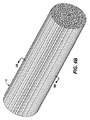
本明細書で使用する場合の「棒」という用語は、本質的に充填された円柱形をした繊維ポリマー足場材を示す。棒を構成する個々の繊維間に空間や溝が存在してもよい。 The term “bar” as used herein refers to a fiber polymer scaffold with an essentially filled cylindrical shape. There may be spaces or grooves between the individual fibers that make up the rod.
本明細書で使用する場合の「導管」という用語は、形状が本質的に円筒形の物体を示す。導管は、内壁および外壁と、内径と、外径と、導管の内径ならびにその長さによって画定される内部空間とを有する。導管を構成する個々の繊維間に空間や溝が存在してもよい。 The term “conduit” as used herein refers to an object that is essentially cylindrical in shape. The conduit has inner and outer walls, an inner diameter, an outer diameter, and an interior space defined by the inner diameter of the conduit and its length. There may be spaces or grooves between the individual fibers that make up the conduit.
本明細書で使用する場合の「充填導管」という用語は、内部空間の一部がフィラー材料からなる導管を示す。このフィラー材料が繊維ポリマー足場材であっても構わない。充填導管を構成する個々の繊維間に空間や溝が存在してもよい。 The term “filled conduit” as used herein refers to a conduit in which a portion of the interior space is made of filler material. This filler material may be a fiber polymer scaffold. There may be spaces or grooves between the individual fibers that make up the filling conduit.
本明細書で使用する場合の「継ぎ目」または「継ぎ合わされた」という用語は、2つのセクションを、かみ合わせ、接合または重ね合わせることによって形成される結合部分を示す。これらの2つのセクションは、縫合糸などの機械的手段によって、あるいは、アニーリングまたは接着剤などの化学的手段によって一緒に保持可能なものである。たとえば、シートのひとつの領域をもうひとつの領域に接合することで、継ぎ目が形成される。 As used herein, the term “seam” or “joined” refers to a joint formed by interlocking, joining, or overlapping two sections. These two sections can be held together by mechanical means such as sutures or by chemical means such as annealing or adhesive. For example, a seam is formed by joining one region of a sheet to another region.
本明細書で使用する場合の「シームレス」という用語は、継ぎ目がないことを示す。 As used herein, the term “seamless” indicates seamless.
「細胞」という用語は、単数形(「細胞(cell)」)または複数形(「細胞(cells)」)の状態を示し得る。 The term “cell” may refer to a singular (“cell”) or plural (“cells”) state.
本明細書で使用する場合の「細胞外マトリクス成分」という用語は、ラミニン、コラーゲン、フィブロネクチンおよびエラスチンから選択される一つである。 The term “extracellular matrix component” as used herein is one selected from laminin, collagen, fibronectin and elastin.
本明細書で使用する場合の「ステント」という用語は、特に金属および有機ポリマーで製造できるチューブである。ステントを有機ポリマーで製造する場合、このポリマーは本明細書に記載されているようなナノ繊維ポリマー足場材またはマイクロ繊維ポリマー足場材ではない。言葉を変えると、ステントを繊維ポリマー足場材で製造する場合、繊維の平均直径は100ミクロンから約50センチメートルになる。場合によっては、ステント全体が第1の直径から第2の直径に膨脹可能であり、第2の直径は第1の直径よりも大きい。 The term “stent” as used herein is a tube that can be made in particular of metals and organic polymers. When the stent is made of an organic polymer, the polymer is not a nanofiber polymer scaffold or a microfiber polymer scaffold as described herein. In other words, when the stent is made of a fiber polymer scaffold, the average fiber diameter is from 100 microns to about 50 centimeters. In some cases, the entire stent can be expanded from a first diameter to a second diameter, the second diameter being larger than the first diameter.
II.組成物
これらの組成物は、ポリマー足場材を含み得る。これらのポリマー足場材は、マイクロ繊維ポリマー足場材またはナノ繊維ポリマー足場材などの繊維ポリマー足場材であってもよい。これらのポリマー足場材はまた、微小パターンが形成されたポリマー足場材であってもよい。本発明の組成物および/またはポリマー足場材は、任意に、整列されていないものであってもよいし、長手方向または円周方向などに整列されたものであってもよい。本発明の組成物および/またはポリマー足場材は、任意に、シート、十字シート、導管、棒または充填導管などの形状に形成可能なものである。本発明の組成物および/またはポリマー足場材は、継ぎ目のあるものであってもよいし、シームレスであってもよい。本発明の組成物またはポリマーはまた、任意に、細胞、生体分子または薬学的に許容される賦形剤などの材料を含むものであってもよい。これらのアライメント、形状および別の成分は、生物学的機能を改善または再生または代用する際の一助となり得る。本発明の組成物は、ステントを含まない。生物学的機能を改善、再生または代用する目的で、この組成物を組織工学において使用することができる。
II. Compositions These compositions may comprise a polymer scaffold. These polymer scaffolds may be fiber polymer scaffolds such as microfiber polymer scaffolds or nanofiber polymer scaffolds. These polymer scaffolds may also be polymer scaffolds with micropatterns formed. The compositions and / or polymer scaffolds of the present invention may optionally be unaligned, aligned in the longitudinal direction or circumferential direction, etc. The compositions and / or polymer scaffolds of the present invention can optionally be formed into shapes such as sheets, cross sheets, conduits, rods or filled conduits. The composition and / or polymer scaffold of the present invention may be seamed or seamless. The compositions or polymers of the present invention may also optionally include materials such as cells, biomolecules or pharmaceutically acceptable excipients. These alignments, shapes, and other components can help improve or regenerate or substitute biological functions. The composition of the present invention does not include a stent. The composition can be used in tissue engineering for the purpose of improving, regenerating or substituting biological function.
II.a)繊維ポリマー足場材
第1の態様では、本発明は、繊維ポリマー足場材を含む組成物を提供するものである。繊維ポリマー足場材は、さまざまな直径を有しうる繊維を含む。例示的実施形態では、繊維ポリマー足場材の繊維の平均直径は、約0.1ナノメートルから約50000ナノメートルである。例示的な別の実施形態では、繊維ポリマー足場材の繊維の平均直径は約25ナノメートルから約25,000ナノメートルである。例示的実施形態では、繊維ポリマー足場材の繊維の平均直径は約50ナノメートルから約20,000ナノメートルである。例示的実施形態では、繊維ポリマー足場材の繊維の平均直径は約100ナノメートルから約5,000ナノメートルである。例示的実施形態では、繊維ポリマー足場材の繊維の平均直径は約1,000ナノメートルから約20,000ナノメートルである。例示的実施形態では、繊維ポリマー足場材の繊維の平均直径は約10ナノメートルから約1,000ナノメートルである。例示的実施形態では、繊維ポリマー足場材の繊維の平均直径は約2,000ナノメートルから約10,000ナノメートルである。例示的実施形態では、繊維ポリマー足場材の繊維の平均直径は約0.5ナノメートルから約100ナノメートルである。例示的実施形態では、繊維ポリマー足場材の繊維の平均直径は約0.5ナノメートルから約50ナノメートルである。例示的実施形態では、繊維ポリマー足場材の繊維の平均直径は約1ナノメートルから約35ナノメートルである。例示的実施形態では、繊維ポリマー足場材の繊維の平均直径は約2ナノメートルから約25ナノメートルである。例示的実施形態では、繊維ポリマー足場材の繊維の平均直径は約90ナノメートルから約1,000ナノメートルである。例示的実施形態では、繊維ポリマー足場材の繊維の平均直径は約500ナノメートルから約1,000ナノメートルである。
II. a) Fiber polymer scaffold In a first aspect, the present invention provides a composition comprising a fiber polymer scaffold. The fiber polymer scaffold includes fibers that can have various diameters. In an exemplary embodiment, the fiber polymer scaffold has an average fiber diameter of about 0.1 nanometers to about 50,000 nanometers. In another exemplary embodiment, the fiber polymer scaffold has an average fiber diameter of about 25 nanometers to about 25,000 nanometers. In an exemplary embodiment, the fiber polymer scaffold has an average fiber diameter of about 50 nanometers to about 20,000 nanometers. In an exemplary embodiment, the fiber polymer scaffold has an average fiber diameter of about 100 nanometers to about 5,000 nanometers. In an exemplary embodiment, the fiber polymer scaffold has an average fiber diameter of about 1,000 nanometers to about 20,000 nanometers. In an exemplary embodiment, the fiber polymer scaffold has an average fiber diameter of about 10 nanometers to about 1,000 nanometers. In an exemplary embodiment, the fiber polymer scaffold has an average fiber diameter of about 2,000 nanometers to about 10,000 nanometers. In an exemplary embodiment, the fiber polymer scaffold has an average fiber diameter of about 0.5 nanometers to about 100 nanometers. In an exemplary embodiment, the fiber polymer scaffold has an average fiber diameter of about 0.5 nanometers to about 50 nanometers. In an exemplary embodiment, the fiber polymer scaffold has an average fiber diameter of about 1 nanometer to about 35 nanometers. In an exemplary embodiment, the fiber polymer scaffold has an average fiber diameter of about 2 nanometers to about 25 nanometers. In an exemplary embodiment, the fiber polymer scaffold has an average fiber diameter of about 90 nanometers to about 1,000 nanometers. In an exemplary embodiment, the fiber polymer scaffold has an average fiber diameter of about 500 nanometers to about 1,000 nanometers.
例示的実施形態では、繊維ポリマー足場材は、ナノ繊維ポリマー足場材およびマイクロ繊維ポリマー足場材から選択される一つである。マイクロ繊維ポリマー足場材がミクロン規模の特徴(平均繊維径約1,000ナノメートルから約50,000ナノメートル、特に約1,000ナノメートルから約20,000ナノメートル)を持つのに対し、ナノ繊維ポリマー足場材はサブミクロン規模の特徴(平均繊維径約10ナノメートルから約1,000ナノメートル、特に約50ナノメートルから約1,000ナノメートル)を持つ。これらのポリマー足場材については各々、野生型のコラーゲンフィブリルまたは他の細胞外マトリクスなどの治療部分における物理的な構造に似たものとすることができる。 In an exemplary embodiment, the fiber polymer scaffold is one selected from nanofiber polymer scaffolds and microfiber polymer scaffolds. While the microfiber polymer scaffold has micron-scale features (average fiber diameter of about 1,000 nanometers to about 50,000 nanometers, especially about 1,000 nanometers to about 20,000 nanometers) Fiber polymer scaffolds have sub-micron scale characteristics (average fiber diameters of about 10 nanometers to about 1,000 nanometers, especially about 50 nanometers to about 1,000 nanometers). Each of these polymer scaffolds can resemble the physical structure in the therapeutic moiety, such as wild-type collagen fibrils or other extracellular matrix.
合成および/または天然源由来のさまざまなポリマーを利用して、これらの繊維ポリマー足場材を構成することができる。繊維については、1種類のモノマーまたはサブユニットから作ることが可能である。たとえば、乳酸またはポリ乳酸あるいはグリコール酸またはポリグリコール酸を利用して、ポリ(ラクチド)(PLA)またはポリ(L−ラクチド)(PLLA)ナノ繊維またはポリ(グリコリド)(PGA)ナノ繊維を形成することができる。また、2種類以上のモノマーまたはサブユニットから繊維を作り、コポリマー、ターポリマーなどを形成することも可能である。たとえば、乳酸またはポリ乳酸をグリコール酸またはポリグリコール酸と組み合わせ、コポリマー・ポリ(ラクチド−co−グリコリド)(PLGA)を形成することができる。本発明において役立つ他のコポリマーとしては、ポリ(エチレン−co−ビニル)アルコール)があげられる。例示的実施形態では、繊維は、脂肪族ポリエステル、ポリアルキレンオキシド、ポリジメチルシロキサン、ポリビニルアルコール、ポリリシン、コラーゲン、ラミニン、フィブロネクチン、エラスチン、アルギン酸塩、フィブリン、ヒアルロン酸、プロテオグリカン、ポリペプチドおよびこれらの組み合わせから選択される一つであるポリマーまたはサブユニットを含む。例示的な別の実施形態では、繊維は、脂肪族ポリエステル、ポリアルキレンオキシド、ポリジメチルシロキサン、ポリビニルアルコール、ポリリシン、コラーゲン、ラミニン、フィブロネクチン、エラスチン、アルギン酸塩、フィブリン、ヒアルロン酸、プロテオグリカン、ポリペプチドおよびこれらの組み合わせから選択される2種類のポリマーまたはサブユニットを含む。例示的な別の実施形態では、繊維は、脂肪族ポリエステル、ポリアルキレンオキシド、ポリジメチルシロキサン、ポリビニルアルコール、ポリリシン、コラーゲン、ラミニン、フィブロネクチン、エラスチン、アルギン酸塩、フィブリン、ヒアルロン酸、プロテオグリカン、ポリペプチドおよびこれらの組み合わせから選択される3種類のポリマーまたはサブユニットを含む。例示的実施形態では、脂肪族ポリエステルは直鎖状または分枝状である。例示的な別の実施形態では、直鎖脂肪族ポリエステルは、乳酸(D−またはL−)、ラクチド、ポリ(乳酸)、ポリ(ラクチド)グリコール酸、ポリ(グリコール酸)、ポリ(グリコリド)、グリコリド、ポリ(ラクチド−co−グリコリド)、ポリ(乳酸−co−グリコール酸)、ポリカプロラクトンおよびこれらの組み合わせから選択される一つである。例示的な別の実施形態では、脂肪族ポリエステルは、分枝状であり、乳酸(D−またはL−)、ラクチド、ポリ(乳酸)、ポリ(ラクチド)グリコール酸、ポリ(グリコール酸)、ポリ(グリコリド)、グリコリド、ポリ(ラクチド−co−グリコリド)、ポリ(乳酸−co−グリコール酸)、ポリカプロラクトンならびに、リンカーまたは生体分子と接合されたこれらの組み合わせから選択されるものを少なくとも1種含む。例示的実施形態では、前記ポリアルキレンオキシドが、ポリエチレンオキシド、ポリエチレングリコール、ポリ酸化プロピレン、ポリプロピレングリコールおよびこれらの組み合わせから選択される一つである。 A variety of polymers from synthetic and / or natural sources can be utilized to construct these fiber polymer scaffolds. For fibers, it can be made from a single monomer or subunit. For example, lactic acid or polylactic acid or glycolic acid or polyglycolic acid is used to form poly (lactide) (PLA) or poly (L-lactide) (PLLA) nanofibers or poly (glycolide) (PGA) nanofibers be able to. It is also possible to make fibers from two or more types of monomers or subunits to form copolymers, terpolymers, and the like. For example, lactic acid or polylactic acid can be combined with glycolic acid or polyglycolic acid to form a copolymer poly (lactide-co-glycolide) (PLGA). Other copolymers useful in the present invention include poly (ethylene-co-vinyl) alcohol). In exemplary embodiments, the fibers are aliphatic polyester, polyalkylene oxide, polydimethylsiloxane, polyvinyl alcohol, polylysine, collagen, laminin, fibronectin, elastin, alginate, fibrin, hyaluronic acid, proteoglycan, polypeptides and combinations thereof A polymer or subunit that is one selected from: In another exemplary embodiment, the fibers are aliphatic polyester, polyalkylene oxide, polydimethylsiloxane, polyvinyl alcohol, polylysine, collagen, laminin, fibronectin, elastin, alginate, fibrin, hyaluronic acid, proteoglycan, polypeptide and It contains two types of polymers or subunits selected from these combinations. In another exemplary embodiment, the fibers are aliphatic polyester, polyalkylene oxide, polydimethylsiloxane, polyvinyl alcohol, polylysine, collagen, laminin, fibronectin, elastin, alginate, fibrin, hyaluronic acid, proteoglycan, polypeptide and It includes three types of polymers or subunits selected from these combinations. In exemplary embodiments, the aliphatic polyester is linear or branched. In another exemplary embodiment, the linear aliphatic polyester is lactic acid (D- or L-), lactide, poly (lactic acid), poly (lactide) glycolic acid, poly (glycolic acid), poly (glycolide), One selected from glycolide, poly (lactide-co-glycolide), poly (lactic acid-co-glycolic acid), polycaprolactone, and combinations thereof. In another exemplary embodiment, the aliphatic polyester is branched and is lactic acid (D- or L-), lactide, poly (lactic acid), poly (lactide) glycolic acid, poly (glycolic acid), poly (Glycolide), glycolide, poly (lactide-co-glycolide), poly (lactic acid-co-glycolic acid), polycaprolactone, and at least one selected from a combination thereof combined with a linker or biomolecule . In an exemplary embodiment, the polyalkylene oxide is one selected from polyethylene oxide, polyethylene glycol, polypropylene oxide, polypropylene glycol, and combinations thereof.
いくつかの実施形態では、繊維ポリマー足場材は、1本の連続繊維からなる。他の実施形態では、繊維ポリマー足場材は、少なくとも2本、3本、4本または5本の繊維からなる。例示的実施形態では、繊維ポリマー足場材の繊維の数は、2から100,000から選択される一つである。例示的実施形態では、繊維ポリマー足場材の繊維数は、2から50,000から選択される一つである。例示的実施形態では、繊維ポリマー足場材の繊維の数は、50,000から100,000から選択される一つである。例示的実施形態では、繊維ポリマー足場材の繊維の数は、10から20,000から選択される一つである。例示的実施形態では、繊維ポリマー足場材の繊維の数は、15から1,000から選択される一つである。 In some embodiments, the fiber polymer scaffold consists of one continuous fiber. In other embodiments, the fiber polymer scaffold consists of at least 2, 3, 4, or 5 fibers. In an exemplary embodiment, the number of fibers of the fiber polymer scaffold is one selected from 2 to 100,000. In an exemplary embodiment, the number of fibers of the fiber polymer scaffold is one selected from 2 to 50,000. In an exemplary embodiment, the number of fibers of the fiber polymer scaffold is one selected from 50,000 to 100,000. In an exemplary embodiment, the number of fibers of the fiber polymer scaffold is one selected from 10 to 20,000. In an exemplary embodiment, the number of fibers of the fiber polymer scaffold is one selected from 15 to 1,000.
繊維ポリマー足場材は、少なくとも1種類の組成物の繊維を含み得る。例示的実施形態では、繊維ポリマー足場材は、多数の異なるタイプの繊維を含み、その数は、1、2、3、4、5、6、7、8、9および10から選択される一つである。 The fiber polymer scaffold may comprise at least one composition fiber. In an exemplary embodiment, the fiber polymer scaffold comprises a number of different types of fibers, the number being one selected from 1, 2, 3, 4, 5, 6, 7, 8, 9 and 10. It is.
例示的な別の実施形態では、繊維ポリマー足場材の繊維は生分解性である。例示的な別の実施形態では、繊維ポリマー足場材の繊維は、生分解性ポリマーを含む。例示的な別の実施形態では、生分解性ポリマーは、乳酸およびグリコール酸から選択される一つであるモノマーを含む。例示的な別の実施形態では、生分解性ポリマーは、ポリ(乳酸)、ポリ(グリコール酸)またはこれらのコポリマーである。好ましい生分解性ポリマーは、ポリ(乳酸)およびポリ(グリコール酸)などの臨床用としてFDA承認済みのポリマーである。例示的な別の実施形態では、本発明の生分解性ポリマー足場材を利用して、培養組織の形態形成をガイドし、組織構築後に徐々に分解させることが可能である。ポリマーの分解速度については、組織の生成速度に合うよう当業者が調節可能なものである。たとえば、短時間で生分解されるポリマーが望ましい場合、約50:50のPLGAの組み合わせを選択することができる。ポリマー足場材生分解性を増やすための別の方法として、さらに親水性の高いコポリマー(たとえば、ポリエチレングリコール)を選択する、分子量が高いと分解速度が遅くなることが多いため、ポリマーの分子量を落とす、多孔性が高く繊維密度が低いと吸水率が上がって分解が速まることが多いため、多孔性または繊維密度を変更するといったことがあげられる。例示的な別の実施形態では、組織は、筋肉組織、維管束組織、神経組織、脊髄組織および皮膚組織から選択される一つである。例示的な別の実施形態では、生分解性繊維足場材を利用して、培養筋肉組織の形態形成をガイドし、筋芽細胞、筋管および骨格筋組織構築後に、徐々に分解することが可能である。 In another exemplary embodiment, the fibers of the fiber polymer scaffold are biodegradable. In another exemplary embodiment, the fibers of the fiber polymer scaffold comprise a biodegradable polymer. In another exemplary embodiment, the biodegradable polymer comprises a monomer that is one selected from lactic acid and glycolic acid. In another exemplary embodiment, the biodegradable polymer is poly (lactic acid), poly (glycolic acid), or a copolymer thereof. Preferred biodegradable polymers are FDA approved polymers for clinical use such as poly (lactic acid) and poly (glycolic acid). In another exemplary embodiment, the biodegradable polymer scaffold of the present invention can be utilized to guide morphogenesis of cultured tissue and gradually degrade after tissue construction. The polymer degradation rate can be adjusted by those skilled in the art to match the tissue production rate. For example, if a polymer that biodegrades in a short time is desired, a combination of about 50:50 PLGA can be selected. Another way to increase the biodegradability of polymer scaffolds is to select a more hydrophilic copolymer (eg, polyethylene glycol). The higher the molecular weight, the slower the degradation rate, so the molecular weight of the polymer is reduced. When the porosity is high and the fiber density is low, the water absorption rate is increased and the decomposition is often accelerated, so that the porosity or the fiber density is changed. In another exemplary embodiment, the tissue is one selected from muscle tissue, vascular tissue, nerve tissue, spinal cord tissue and skin tissue. In another exemplary embodiment, a biodegradable fiber scaffold can be utilized to guide the morphogenesis of cultured muscle tissue and gradually degrade after myoblast, myotube and skeletal muscle tissue construction It is.
繊維ポリマー足場材の製造方法
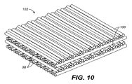
本発明のポリマー足場材は、さまざまな方法で作製可能なものである。例示的実施形態では、ポリマー足場材を電界紡糸によって作製することができる。電界紡糸とは、静電場と電導性流体との間の相互作用を利用する電導性流体の噴霧プロセスである。電導性流体(半希釈ポリマー溶液またはポリマー融液など)に外部静電場を印加すると、懸濁された円錐形の液滴が形成され、これによって液滴の表面張力が電場と平衡する。静電場が液体の表面張力を超えるだけの十分な強さになったら、静電噴霧を行う。すると、液滴が不安定になり、液滴表面から微小な噴流が飛び出してくる。この材料がアースをとったターゲットに近づくときに、比較的微細な繊維すなわち径の小さな繊維を含む、互いに絡み合った織物としてこの材料を捕集することができる。これらの径の小さな繊維からこのようにして得られるフィルム(または膜)は、体積比に対して表面積が極めて大きく、孔のサイズが小さい。電界紡糸装置の詳細な説明については、Zong, et al., Polymer, 43(16):4403-4412 (2002); Rosen et al., Ann Plast Surg., 25:375-87 (1990) Kim, K., Biomaterials 2003, 24, (27), 4977-85; Zong, X., Biomaterials 2005, 26, (26), 5330-8に掲載されている。電界紡糸(electrospinninng)後、押出および成形を利用して、ポリマーをさらに成形することが可能である。繊維の組織構造を調整して整列された繊維ポリマー足場材にする目的では、パターン形成した電極、ワイヤドラムコレクタあるいは、一軸延伸などの後処理法を用いる方法がうまくいっている。Zong, X., Biomaterials 2005, 26, (26), 5330-8; Katta, P., Nano Lett 2004, 4, (11), 2215-2218; Li, D., Nano Lett 2005, 5, (5), 913-6。
Manufacturing method of fiber polymer scaffold The polymer scaffold of the present invention can be produced by various methods. In an exemplary embodiment, the polymer scaffold can be made by electrospinning. Electrospinning is a conductive fluid spraying process that utilizes the interaction between an electrostatic field and a conductive fluid. When an external electrostatic field is applied to a conductive fluid (such as a semi-diluted polymer solution or polymer melt), suspended conical droplets are formed, thereby balancing the surface tension of the droplets with the electric field. When the electrostatic field is strong enough to exceed the surface tension of the liquid, electrostatic spraying is performed. Then, the liquid droplet becomes unstable, and a fine jet is ejected from the surface of the liquid droplet. As this material approaches the grounded target, it can be collected as an intertwined fabric that includes relatively fine or small diameter fibers. Films (or membranes) thus obtained from these small diameter fibers have a very large surface area and small pore size relative to the volume ratio. For a detailed description of the electrospinning apparatus, see Zong, et al., Polymer, 43 (16): 4403-4412 (2002); Rosen et al., Ann Plast Surg., 25: 375-87 (1990) Kim, K., Biomaterials 2003, 24, (27), 4977-85; Zong, X., Biomaterials 2005, 26, (26), 5330-8. After electrospinninng, the polymer can be further shaped using extrusion and molding. For the purpose of adjusting the fiber structure to provide an aligned fiber polymer scaffold, methods using post-treatment methods such as patterned electrodes, wire drum collectors or uniaxial stretching have been successful. Zong, X., Biomaterials 2005, 26, (26), 5330-8; Katta, P., Nano Lett 2004, 4, (11), 2215-2218; Li, D.,
ポリマー溶液については、いくつかの方法のうちのひとつで生成することができる。一方法として、モノマーを重合し、その結果生じたポリマーを適当な溶媒に溶解させることがあげられる。このプロセスをシリンジアセンブリで行うこともできるし、あるいはこれを後からシリンジアセンブリに注入することもできる。別の方法として、市販のポリマー溶液または市販のポリマーを購入し、これらを溶解させてポリマー溶液を生成することがある。たとえば、PLLAはDuPont(Wilmington, DE)から購入可能であり、ポリ(ラクチド−co−グリコリド)は、Ethicon(Somerville, NJ)およびBirmingham Polymers(Birmingham, AL)、Sigma-Aldrich(St. Louis, MO)およびPolysciences(Warrington, PA)から購入可能である。他の製造業者として、Lactel Absorbable Polymers(Pelham, AL)がある。細胞および生体分子などの本発明の別のポリマー足場材成分も、Invitrogen(San Diego, CA)、Cambrex(Walkersville, MD)、Sigma-Aldrich, Peprotech(Rocky Hill, NJ)、R&D Systems(Minneapolis, MN)、ATCC(Manassas, VA)、Pierce Biotechnology(Rockford, IL)などの供給業者から商業入手可能である。 The polymer solution can be produced in one of several ways. One method is to polymerize the monomers and dissolve the resulting polymer in a suitable solvent. This process can be performed on the syringe assembly or it can be subsequently injected into the syringe assembly. Another method is to purchase a commercially available polymer solution or a commercially available polymer and dissolve them to form a polymer solution. For example, PLLA can be purchased from DuPont (Wilmington, DE), and poly (lactide-co-glycolide) can be obtained from Ethicon (Somerville, NJ) and Birmingham Polymers (Birmingham, AL), Sigma-Aldrich (St. Louis, MO). ) And Polysciences (Warrington, PA). Another manufacturer is Lactel Absorbable Polymers (Pelham, AL). Other polymer scaffold components of the present invention such as cells and biomolecules are also described in Invitrogen (San Diego, CA), Cambrex (Walkersville, MD), Sigma-Aldrich, Peprotech (Rocky Hill, NJ), R & D Systems (Minneapolis, MN). ), ATCC (Manassas, VA), Pierce Biotechnology (Rockford, IL) and the like.
ポリマー足場材の形成に用いられるポリマーを、まずは溶媒に溶解させる。溶媒は、ポリマーのモノマーおよび/またはサブユニットを溶解させ、電導と電界紡糸が可能なポリマー溶液を提供できるものであれば、どのような溶媒であってもよい。代表的な溶媒として、N,N−ジメチルホルムアミド(DMF)、テトラヒドロフラン(THF)、メチレンクロリド、ジオキサン、エタノール、ヘキサフルオロイソプロパノール(HFIP)、クロロホルム、水およびこれらの組み合わせから選択される溶媒があげられる。 The polymer used to form the polymer scaffold is first dissolved in a solvent. The solvent may be any solvent as long as it can dissolve polymer monomers and / or subunits and provide a polymer solution capable of conducting and electrospinning. Typical solvents include N, N-dimethylformamide (DMF), tetrahydrofuran (THF), methylene chloride, dioxane, ethanol, hexafluoroisopropanol (HFIP), chloroform, water, and combinations thereof. .
ポリマー溶液は、任意に、電界紡糸工程を容易にするための過剰な電荷効果を生成する塩を含有するものであってもよい。好適な塩の例として、NaCl、KH2PO4、K2HPO4、KIO3、KCl、MgSO4、MgCl2、NaHCO3、CaCl2またはこれらの塩の混合物があげられる。 The polymer solution may optionally contain salts that produce excessive charge effects to facilitate the electrospinning process. Examples of suitable salts include NaCl, KH 2 PO 4 , K 2 HPO 4 , KIO 3 , KCl, MgSO 4 , MgCl 2 , NaHCO 3 , CaCl 2 or mixtures of these salts.
電導性流体を形成するポリマー溶液は、好ましくはポリマー濃度が約1から約80wt%、より好ましくは約8から約60wt%の範囲になる。電導性流体は、好ましくは粘度が約50から約2000mPa・s、より好ましくは約200から約700mPa・sの範囲になる。 The polymer solution that forms the conductive fluid preferably has a polymer concentration in the range of about 1 to about 80 wt%, more preferably about 8 to about 60 wt%. The conductive fluid preferably has a viscosity in the range of about 50 to about 2000 mPa · s, more preferably about 200 to about 700 mPa · s.
電界紡糸工程で発生する電場は、好ましくは約5から約100キロボルト(kV)、より好ましくは約10から約50kVの範囲となる。紡糸口金(または電極)への電導性流体の供給量は、好ましくは約0.1から約1000マイクロリットル/分、より好ましくは約1から約250マイクロリットル/分の範囲となる。 The electric field generated by the electrospinning process is preferably in the range of about 5 to about 100 kilovolts (kV), more preferably about 10 to about 50 kV. The amount of conductive fluid supplied to the spinneret (or electrode) is preferably in the range of about 0.1 to about 1000 microliters / minute, more preferably about 1 to about 250 microliters / minute.
1個または複数個の紡糸口金がプラットフォーム上に配置されており、プラットフォームは調節可能であり、かつプラットフォームとコレクタ接地基板との間の距離を変えることが可能である。この距離は、ポリマーとコレクタ接地基板との接触前に、溶媒が本質的に完全に蒸発できる距離であれば、どのような距離であってもよい。例示的実施形態では、この距離は、1cmから25cmまで可変である。一般に、コレクタ接地基板とプラットフォームとの間の距離が長くなると、形成される繊維は細くなっていく。 One or more spinnerets are disposed on the platform, the platform is adjustable, and the distance between the platform and the collector grounding substrate can be varied. This distance can be any distance as long as the solvent can be essentially completely evaporated before the polymer contacts the collector grounding substrate. In an exemplary embodiment, this distance is variable from 1 cm to 25 cm. In general, as the distance between the collector grounding substrate and the platform increases, the formed fibers become thinner.
回転式のマンドレルが必要な電界紡糸の事例では、多くの場合ドリルチャックを介してマンドレルを機械的にモーターに取り付ける。例示的実施形態では、モーターは、1分あたり約1回転(rpm)から約500rpmの速度でマンドレルを回転させる。例示的実施形態では、モーター回転速度は約200rpmから約500rpmである。例示的な別の実施形態では、モーター回転速度は約1rpmから約100rpmである。 In the case of electrospinning where a rotating mandrel is required, the mandrel is often mechanically attached to the motor via a drill chuck. In an exemplary embodiment, the motor rotates the mandrel at a speed of about 1 revolution per minute (rpm) to about 500 rpm. In an exemplary embodiment, the motor rotation speed is from about 200 rpm to about 500 rpm. In another exemplary embodiment, the motor rotation speed is from about 1 rpm to about 100 rpm.
別の実施形態または電界紡糸工程および装置に対する変形例が本明細書に記載される。 Alternative embodiments or variations to the electrospinning process and apparatus are described herein.
電導性流体の電気的/機械的特性の変形
電界紡糸によって生成される、このようにして得られる膜の特性は、電導性流体の電気的特性および機械的特性に影響されることになる。イオン性無機/有機化合物を加えることで、ポリマー溶液の電導度を劇的に変えることが可能である。ポリマー溶液の電磁流体力学的特性は、物理的特性、機械的特性(流体の表面張力、粘度および粘弾性挙動など)、電気的特性(流体の電荷密度および分極率)の組み合わせに左右されることがある。たとえば、より広範囲にわたる条件で、静電場が噴流の形状と噴流の流れに影響を及ぼすことができるように、ポリマー溶液に界面活性剤を加えることで、流体表面張力を小さくすることができる。定圧または一定流量のいずれかで流量を制御可能なシリンジポンプを連結することで、電導性流体の粘度の影響を軽減することができる。
Deformation of the electrical / mechanical properties of the conducting fluid The properties of the membrane thus obtained produced by electrospinning will be influenced by the electrical and mechanical properties of the conducting fluid. By adding ionic inorganic / organic compounds, it is possible to dramatically change the conductivity of the polymer solution. The magnetohydrodynamic properties of polymer solutions depend on a combination of physical properties, mechanical properties (such as fluid surface tension, viscosity and viscoelastic behavior), and electrical properties (fluid charge density and polarizability). There is. For example, the surface tension of the fluid can be reduced by adding a surfactant to the polymer solution so that the electrostatic field can affect the jet shape and jet flow over a wider range of conditions. By connecting a syringe pump capable of controlling the flow rate at either a constant pressure or a constant flow rate, the influence of the viscosity of the conductive fluid can be reduced.
電極の設計
本発明に係る膜を生成するための別の実施形態では、繊維のサイズをさらに制御しやすくするために、電界紡糸時の噴流形成工程をさらに改善する。上述したような帯電した紡糸口金と接地板とを単に用いるのではなく、正に帯電した紡糸口金で同じようにポリマー溶液の液滴を形成し、中央に小さな出口穴のある平板電極でジェット流を形成するようにする。この出口穴は、平板電極にジェット流を通すための手段となる。よって、正に帯電した紡糸口金表面のポリマー液滴が典型的に2〜3mmの寸法で、平板電極が紡糸口金から約10mmの距離にある場合、適度な静電電位を発生させることができる。2つの電極間の距離が短いと、静電電位がかなり低くなりかねない。しかしながら、得られる電場強度は電界紡糸工程には十分な強さになり得る。紡糸口金の電位を変えることで、噴流形成を制御および調節することが可能である。このような電極構成は、紡糸口金に対して必要な印加電位を、一般に約15キロボルト(kV)から一般に約1.5〜2kV(接地板電位に対して)まで大幅に減らすべきものである。安定した噴流形成のために必要とされる正確な紡糸口金電位は、特定の電導性流体の電気的特性/機械的特性に左右されることになる。
Electrode Design In another embodiment for producing a membrane according to the present invention, the jet forming process during electrospinning is further improved in order to further control the fiber size. Rather than simply using a charged spinneret and ground plate as described above, a droplet of polymer solution is formed in the same way with a positively charged spinneret, and a jet flow is generated by a flat plate electrode with a small outlet hole in the center. To form. This outlet hole is a means for passing a jet stream through the flat plate electrode. Thus, when a positively charged polymer droplet on the spinneret surface is typically 2 to 3 mm in size and the plate electrode is at a distance of about 10 mm from the spinneret, a moderate electrostatic potential can be generated. If the distance between the two electrodes is short, the electrostatic potential can be quite low. However, the electric field strength obtained can be strong enough for the electrospinning process. By changing the electric potential of the spinneret, it is possible to control and regulate jet formation. Such an electrode configuration should significantly reduce the applied potential required for the spinneret, typically from about 15 kilovolts (kV) to generally about 1.5-2 kV (relative to the ground plate potential). The exact spinneret potential required for stable jet formation will depend on the electrical / mechanical properties of the particular conducting fluid.
噴流の加速と輸送の制御
本発明のポリマー足場材を生成するための別の好ましい実施形態では、ジェット流の飛行も厳密に制御する。平板電極の出口穴を通るジェット流は、正に帯電している。このジェット流は、外部電場の閉じ込めがなくても飛行時に自ら真っ直ぐになる傾向にあるが、噴流はその軌道ですぐに不安定になってしまう。言葉を変えると、帯電したジェット流の焦点がずれ、流体の微視的特性および巨視的特性の制御が不能となる。この不安定さについては、慎重に設計したプローブ電極を平板電極のすぐ後ろで使用し、(等しく)間隔をあけた一連の平板電極用いることで、取り除くことができる。電極アセンブリ(または複合電極)すなわち、プローブ電極および平板電極は、(真っ直ぐな)飛行経路に沿って静電電位を均一に分布させることができる。紡糸口金のベース電位を(接地電位での)ターゲットよりも約+20から+30kV高くすれば加速度ポテンシャルが形成されるのに対し、プローブ電極の静電電位については平板電極のベース電位よりもわずかに低く調節することができる。複合電極は、ジェット流を所望のターゲット部分まで送ることができる。また、複合電極を利用して、ジェット流を操作することも可能である。静電電位を変えることでジェット流の加速度が変わり、成形されるポリマー繊維の直径も変化することになる。この静電電位の変動によってジェット流の安定性が変化するため、複合電極の対応する変化を利用して、新たなジェット流を安定させることができる。このような手法は、電界紡糸工程の間に繊維の直径を微調整して変化させるのに利用できるものである。
Jet acceleration and transport control In another preferred embodiment for producing the polymer scaffolds of the present invention, jet flight flight is also tightly controlled. The jet flow through the outlet hole of the plate electrode is positively charged. This jet stream tends to be straight during flight without any external electric field confinement, but the jet becomes unstable immediately in its orbit. In other words, the charged jet stream is defocused, making it impossible to control the microscopic and macroscopic properties of the fluid. This instability can be eliminated by using a carefully designed probe electrode immediately behind the plate electrode and using a series of (equally) spaced plate electrodes. Electrode assemblies (or composite electrodes), i.e., probe and plate electrodes, can distribute the electrostatic potential uniformly along a (straight) flight path. An acceleration potential is formed when the base potential of the spinneret is about +20 to +30 kV higher than the target (at ground potential), whereas the electrostatic potential of the probe electrode is slightly lower than the base potential of the plate electrode. Can be adjusted. The composite electrode can deliver a jet stream to the desired target portion. It is also possible to manipulate the jet flow using a composite electrode. Changing the electrostatic potential changes the acceleration of the jet stream and changes the diameter of the polymer fibers to be molded. Since the stability of the jet flow changes due to the fluctuation of the electrostatic potential, a new jet flow can be stabilized using the corresponding change of the composite electrode. Such a technique can be used to fine tune and change the fiber diameter during the electrospinning process.
噴流の操作
さらに別の実施形態では、高エネルギー物理学の加速器技術で広く用いられている「強集束」(AG : Alternating Gradient)手法を用いてジェット流の焦点を合わせることができる。基本的な考え方は、2対の静電四重極レンズを用いることである。第2のレンズは、電気的勾配が逆(交互)であること以外は第1のレンズと幾何学的配置が同じである。正に帯電したジェット流は、たとえば、第1のレンズの後はxz面で焦点が合わされ、続いて第2のレンズの後にyz面で再び焦点が合わされる。z方向は最初の飛行経路の方向を表すことに注意されたい。四重極の対のうちの一方において電位にさらに三角形の波形を適用することで、ターゲット領域にわたって噴流を掃引することができるため、ジェット流の方向を制御できる。さらに、「掃引」電位のさまざまな波形で、ターゲットに所望のパターンを形成することができる。
Jet Manipulation In yet another embodiment, the jet stream can be focused using the “Alternating Gradient” (AG) technique widely used in high energy physics accelerator technology. The basic idea is to use two pairs of electrostatic quadrupole lenses. The second lens has the same geometrical arrangement as the first lens except that the electrical gradient is reversed (alternate). The positively charged jet stream is, for example, focused on the xz plane after the first lens and subsequently refocused on the yz plane after the second lens. Note that the z direction represents the direction of the first flight path. By applying a further triangular waveform to the potential at one of the quadrupole pairs, the jet can be swept across the target area, thus controlling the direction of the jet flow. Furthermore, the desired pattern can be formed on the target with various waveforms of “sweep” potential.
独特なマンドレルを有する電界紡糸装置
電界紡糸ポリマー繊維は、固定基板または回転基板上に堆積可能なものである。従来、電界紡糸繊維のランダム堆積には固定金属コレクタを利用していた。回転金属マンドレルは電界紡糸時に利用されていた。回転金属マンドレルを用いると、マンドレルの表面に繊維がランダムに堆積し、これによってマンドレルを取り除いた後に導管を生成できる。また、この方法を改変し、マンドレルを高速(>100rpm)で回転させる方法でも円周方向に繊維が整列された導管を生成できることもある。径の大きいおよび/または長さの長い回転ドラムをコレクタ基板として用いる場合、堆積された繊維ポリマー足場材をドラムから切り取って取り除く際に、整列されていない繊維ポリマー足場材と整列された繊維ポリマー足場材のシートが生成されることがある。固定金属コレクタ内に空隙(穴)を形成することで、ギャップの上に堆積される電界紡糸繊維が整列されることが、過去にすでに示されている(Li, D., Wang Y. L., Xia, Y. N., Electrospinning of Polymeric and Ceramic Nanofibers as Uniaxially Aligned Arrays. Nano Letters, 2003. 3(8): p. 1167-71)。しかしながら、整列された三次元の導管または棒を製造することや、長手方向に整列された繊維からなる導管または棒を直接に電界紡糸することについては、Liにも他のどこにも何ら説明されていない。
Electrospinning apparatus with unique mandrels Electrospun polymer fibers are those that can be deposited on a fixed or rotating substrate. Traditionally, fixed metal collectors have been used for random deposition of electrospun fibers. Rotating metal mandrels have been used during electrospinning. With a rotating metal mandrel, fibers can be randomly deposited on the surface of the mandrel, thereby creating a conduit after the mandrel is removed. It may also be possible to produce a conduit with aligned fibers in the circumferential direction by modifying this method and rotating the mandrel at high speed (> 100 rpm). When a large diameter and / or long rotating drum is used as the collector substrate, the fiber polymer scaffold aligned with the unaligned fiber polymer scaffold is removed when the deposited fiber polymer scaffold is removed from the drum. A sheet of material may be generated. It has already been shown in the past that the formation of voids (holes) in a fixed metal collector aligns the electrospun fibers deposited over the gap (Li, D., Wang YL, Xia, YN, Electrospinning of Polymeric and Ceramic Nanofibers as Uniaxially Aligned Arrays. Nano Letters, 2003. 3 (8): p. 1167-71). However, there has been no mention of Li or anywhere else about making aligned three-dimensional conduits or rods or directly electrospinning conduits or rods consisting of longitudinally aligned fibers. Absent.
別の態様では、本発明は、整列された繊維ポリマー足場材を回転式のマンドレル上に電界紡糸するための方法を含む。これらの繊維ポリマー足場材は、利用者が望むどのような配向にも整列可能なものである。例示的実施形態では、足場材は本質的に長手方向または本質的に円周方向に整列される。この方法で作製される繊維ポリマー足場材は、継ぎ目のあるものであってもよいし、シームレスであってもよい。例示的実施形態では、繊維ポリマー足場材はシームレスである。例示的な別の実施形態では、繊維ポリマー足場材は、ポリマー足場材の長手方向の軸に対して本質的に平行な軸に沿ってシームレスである。 In another aspect, the invention includes a method for electrospinning aligned fiber polymer scaffolds onto a rotating mandrel. These fiber polymer scaffolds can be aligned in any orientation desired by the user. In an exemplary embodiment, the scaffold is aligned essentially longitudinally or essentially circumferentially. The fiber polymer scaffold made by this method may be jointed or seamless. In an exemplary embodiment, the fiber polymer scaffold is seamless. In another exemplary embodiment, the fiber polymer scaffold is seamless along an axis that is essentially parallel to the longitudinal axis of the polymer scaffold.
別の態様では、本発明は、シームレス導管、シームレス充填導管およびシームレスな棒の電界紡糸を可能にする独特なマンドレルを含む。例示的な別の実施形態では、シームレス導管、シームレス充填導管およびシームレスな棒は、未整列の繊維配向を有する。例示的な別の実施形態では、シームレス導管、シームレス充填導管およびシームレスな棒の繊維は、整列されている。例示的な別の実施形態では、シームレス導管、シームレス充填導管およびシームレスな棒は、本質的に長手方向に整列された繊維を有する。 In another aspect, the present invention includes a unique mandrel that allows electrospinning of seamless conduits, seamless filled conduits and seamless rods. In another exemplary embodiment, the seamless conduit, seamless fill conduit and seamless bar have unaligned fiber orientation. In another exemplary embodiment, the fibers of the seamless conduit, seamless filling conduit and seamless rod are aligned. In another exemplary embodiment, the seamless conduit, seamless filling conduit and seamless bar have fibers that are essentially longitudinally aligned.
別の態様では、本発明は、モノリシックに形成された導管、充填導管および棒の電界紡糸を可能にする独特なマンドレルを含む。例示的な別の実施形態では、モノリシックに形成された導管、充填導管および棒は、未整列の繊維配向を有する。例示的な別の実施形態では、モノリシックに形成された導管、充填導管および棒の繊維は整列されている。例示的な別の実施形態では、モノリシックに形成された導管、充填導管および棒は、本質的に長手方向に整列された繊維を有する。 In another aspect, the present invention includes a unique mandrel that allows electrospinning of monolithically formed conduits, fill conduits and rods. In another exemplary embodiment, the monolithically formed conduits, filling conduits and rods have an unaligned fiber orientation. In another exemplary embodiment, the monolithically formed conduit, fill conduit and rod fibers are aligned. In another exemplary embodiment, monolithically formed conduits, filling conduits and rods have fibers that are essentially longitudinally aligned.
例示的実施形態では、マンドレルは、マンドレルをその長手方向の軸を中心にして回転可能なモーターアセンブリに取り付けられている。電界紡糸装置では、回転式のマンドレルは接地され、紡糸口金の下に配置されている。紡糸口金の先端にポリマー溶液が供給され、電源によって帯電される。紡糸口金とマンドレルの間に発生する電界は、噴流を形成するための紡糸口金の先端で帯電したポリマー溶液を含む。この噴流はマンドレルに向かって噴霧される。ポリマーがマンドレルの一電導性領域と接触し、続いてマンドレルの第2の電導性領域と接触して、マンドレルの非電導性領域または空隙に繊維が堆積される。これによって、非電導性領域上または空隙内に、整列された繊維が堆積される。マンドレルを回転させることで、整列された繊維が均等に適用された層が得られる。堆積された繊維層はマンドレルの形状またはマンドレル間の空隙の形状に沿っているため、場合によってはシート、場合によっては導管、あるいは場合によっては棒が形成される。シート、導管または棒を含む繊維は、導管または棒の長さに沿って整列され、これによって長手方向に整列された繊維のシート、導管または棒が形成されることになる。例示的実施形態では、導管または棒はシームレスになる。例示的実施形態では、導管または棒は、導管または棒の長軸に対して本質的に平行な軸に沿ってシームレスになる。 In the exemplary embodiment, the mandrel is attached to a motor assembly that can rotate the mandrel about its longitudinal axis. In an electrospinning apparatus, a rotary mandrel is grounded and placed under a spinneret. A polymer solution is supplied to the tip of the spinneret and is charged by a power source. The electric field generated between the spinneret and the mandrel contains a polymer solution charged at the tip of the spinneret to form a jet. This jet is sprayed towards the mandrel. The polymer is contacted with one conductive region of the mandrel, followed by contact with the second conductive region of the mandrel, and fibers are deposited in the non-conductive region or void of the mandrel. This deposits aligned fibers on the non-conducting areas or in the voids. By rotating the mandrel, a layer with evenly applied aligned fibers is obtained. The deposited fiber layer follows the shape of the mandrels or the shape of the gaps between the mandrels, so that in some cases a sheet, in some cases a conduit, or in some cases a rod is formed. The fibers comprising the sheet, conduit or rod are aligned along the length of the conduit or rod, thereby forming a longitudinally aligned sheet, conduit or rod of fibers. In the exemplary embodiment, the conduits or bars are seamless. In an exemplary embodiment, the conduit or bar becomes seamless along an axis that is essentially parallel to the long axis of the conduit or bar.
一実施形態では、本発明は、少なくとも2つの電導性領域と、少なくとも1つの非電導性領域とを有するマンドレルを提供するものである。このようなマンドレルについては、さまざまな方法で設計可能である。マンドレルの例示的な図を図3Bに示し、本発明のシートおよび/または導管を製造するための装置の一部であるマンドレルの例示的な図を、図1、図2、図2Aおよび図2Bに示す。例示的実施形態では、導電性材料が金属である。例示的な別の実施形態では、金属が、鋼およびアルミニウムから選択される一つである。ひとつの事例では、電導性マンドレルの一領域を非導電性材料で被覆することができる。このマンドレルの例示的な断面を図3Dに示す。例示的実施形態では、非導電性材料は、テープ、絶縁用テープ、テフロン(登録商標)およびプラスチックから選択される一つである。別の場合では、少なくとも3つのセクションすなわち、2つの電導性マンドレル領域と、これを相互接続する非導電性領域を有するマンドレルを製造することができる。別の場合では、非導電性領域は、2つの電導性マンドレル領域間に延在する別個の部分である。このマンドレルの例示的な断面を図3Cに示す。マンドレルの電導性領域の上に非電導性領域を配置するか、あるいはマンドレルの2つの電導性領域間で非電導性領域を相互接続することで、マンドレルに別の非電導性領域を加えることも可能である。これらの別の非電導性領域を別の紡糸口金と連動させて用いれば、同じマンドレルで同時に2種類以上の導管を製造しやすくすることができる。一実施形態では、本発明は、少なくとも3つの電導性領域と少なくとも2つの非電導性領域とを有するマンドレルを提供するものである。一実施形態では、本発明は、少なくとも4つの電導性領域と少なくとも3つの非電導性領域とを有するマンドレルを提供するものである。一実施形態では、本発明は、少なくとも5つの電導性領域と少なくとも4つの非電導性領域とを有するマンドレルを提供するものである。 In one embodiment, the present invention provides a mandrel having at least two conductive regions and at least one non-conductive region. Such a mandrel can be designed in various ways. An exemplary view of a mandrel is shown in FIG. 3B, and an exemplary view of a mandrel that is part of an apparatus for manufacturing the seats and / or conduits of the present invention is shown in FIGS. 1, 2, 2A and 2B. Shown in In an exemplary embodiment, the conductive material is a metal. In another exemplary embodiment, the metal is one selected from steel and aluminum. In one case, a region of the conductive mandrel can be coated with a non-conductive material. An exemplary cross section of this mandrel is shown in FIG. 3D. In an exemplary embodiment, the non-conductive material is one selected from tape, insulating tape, Teflon and plastic. In another case, a mandrel having at least three sections, i.e., two conductive mandrel regions and a non-conductive region interconnecting them can be fabricated. In other cases, the non-conductive region is a separate portion that extends between the two conductive mandrel regions. An exemplary cross section of this mandrel is shown in FIG. 3C. It is also possible to place a non-conducting region on the mandrel's conductive region or to add another non-conducting region to the mandrel by interconnecting the non-conducting region between the two conductive regions of the mandrel. Is possible. If these other non-conductive regions are used in conjunction with different spinnerets, it is possible to easily produce two or more types of conduits simultaneously with the same mandrel. In one embodiment, the present invention provides a mandrel having at least three conductive regions and at least two non-conductive regions. In one embodiment, the present invention provides a mandrel having at least four conductive regions and at least three non-conductive regions. In one embodiment, the present invention provides a mandrel having at least 5 conductive regions and at least 4 non-conductive regions.
一実施形態では、本発明は、第1の電導性領域と、第2の電導性領域と、第1の電導性領域と第2の電導性領域との間の空隙とを有するマンドレルを提供するものである。このようなマンドレルについては、さまざまな方法で設計可能である。マンドレルの例示的な図を図3Eに示し、本発明の棒を製造するための装置の一部であるマンドレルの例示的な図を、図6、図7および図7Aに示す。複数の紡糸口金を含む実施形態を図11に示して説明する。例示的実施形態では、導電性材料が金属である。例示的な別の実施形態では、金属は、鋼およびアルミニウムから選択される一つである。例示的実施形態では、マンドレルの各電導性領域は、他の領域と整列されている。例示的実施形態では、マンドレルの各電導性領域は、同一速度で回転できるアセンブリに取り付けられている。これは、マンドレルの各電導性領域にモーターアセンブリを取り付け、各モーターが同一速度で回転するようにすることで実現可能である。また、マンドレルの各電導性領域が同一のモーターに接続されるようにして実現することも可能である。 In one embodiment, the present invention provides a mandrel having a first conductive region, a second conductive region, and a gap between the first conductive region and the second conductive region. Is. Such a mandrel can be designed in various ways. An exemplary view of a mandrel is shown in FIG. 3E, and exemplary views of mandrels that are part of an apparatus for manufacturing the rod of the present invention are shown in FIGS. 6, 7 and 7A. An embodiment including a plurality of spinnerets will be described with reference to FIG. In an exemplary embodiment, the conductive material is a metal. In another exemplary embodiment, the metal is one selected from steel and aluminum. In the exemplary embodiment, each conductive region of the mandrel is aligned with the other region. In the exemplary embodiment, each conductive region of the mandrel is attached to an assembly that can rotate at the same speed. This can be accomplished by attaching a motor assembly to each conductive area of the mandrel so that each motor rotates at the same speed. It is also possible to realize such that each conductive region of the mandrel is connected to the same motor.
電界紡糸の終了後、本発明のポリマー足場材をマンドレルから取り外す。シートとしてのポリマー足場材の場合、マンドレルからシートを剥がすことができる。導管としてのポリマー足場材の場合、モーターアセンブリからマンドレルを取り外した上で、導管を取り外すことができる。いくつかの実施形態では、マンドレルを中央部で分離するか、導管を切断して取り外しを実現することができる。棒としてのポリマー足場材の場合、電導性領域の金属端から棒を剥がすことができる。場合によっては、堆積された繊維の長さが等しくならないこともあり、この場合はポリマー足場材の片端または両端がギザギザの縁になる。任意に、長さが本質的に同じサイズのポリマー足場材とする目的で、ポリマー足場材の端を切断することも可能である。この切断は、ポリマー足場材がマンドレル上にあるうちに実施してもよいし、マンドレルから取り外した後で実施することも可能である。 After completion of electrospinning, the polymer scaffold of the present invention is removed from the mandrel. In the case of a polymer scaffold as a sheet, the sheet can be peeled from the mandrel. In the case of a polymer scaffold as a conduit, the conduit can be removed after the mandrel is removed from the motor assembly. In some embodiments, the mandrel can be separated in the middle or the conduit can be cut to achieve removal. In the case of a polymer scaffold as a rod, the rod can be peeled from the metal end of the conductive region. In some cases, the lengths of the deposited fibers may not be equal, in which case one or both ends of the polymer scaffold will be jagged edges. Optionally, the end of the polymer scaffold can be cut for the purpose of making the polymer scaffold of essentially the same size in length. This cutting may be performed while the polymer scaffold is on the mandrel or may be performed after removal from the mandrel.
本明細書に記載のポリマー足場材の特徴は、さまざまなパラメータを変えることで変更可能なものである。たとえば、単独または組み合わせで、繊維ポリマー足場材の繊維の平均直径を小さくできるいくつかの方法がある。ひとつの方法として、ポリマー溶液にさらに塩を加えることがある。ポリマー溶液にさらに極性の高い溶媒を使用する方法でも、紡糸口金とマンドレルとの距離が長くなるため平均繊維径が小さくなる傾向にある。足場材の直径を小さくする別の方法として、装置の電圧を上げてポリマー濃度を高めることがあげられる。 The characteristics of the polymer scaffold described herein can be altered by changing various parameters. For example, there are several ways that, alone or in combination, can reduce the average fiber diameter of the fiber polymer scaffold. One method is to add more salt to the polymer solution. Even in the method of using a more polar solvent in the polymer solution, the average fiber diameter tends to decrease because the distance between the spinneret and the mandrel becomes longer. Another way to reduce the diameter of the scaffold is to increase the polymer concentration by increasing the device voltage.
いくつかのマンドレルの回転を完了することで、本明細書に記載の方法で多層のポリマー足場材を形成することができる。たとえば、いくつかのマンドレルの回転を完了することで、多層の導管を形成することができる。2種類以上のタイプの層を有する別のポリマー足場材も製造可能である。例示的実施形態では、マンドレルの回転速度を変えることで、繊維の円周方向のアライメントも調節または変更できる。よって、長手方向に整列された内側の層と円周方向に整列された外側の層とを有するポリマー足場材を製造可能である。各層が特定のアライメントを有する多層の中空導管の足場材を製造する目的で、さまざまなマンドレルと回転速度を利用することができる。例示的実施形態では、長手方向に整列された繊維を有する管腔(luminal)層と円周方向に整列された繊維を有する外側の層のある中空の導管形の繊維足場材を作製する。このような足場材を製造するためのひとつの方法として、上述したような非電導性領域を有するマンドレルを用いることがある。マンドレルを低速で回転させ、長手方向に整列された繊維からなる導管形の繊維足場材を形成できるようにする。続いて、マンドレルの回転速度を上げ、これによって電界紡糸繊維を長手方向に整列された繊維導管の周りに円周方向に整列させる。例示的な別の実施形態では、内側の層は長手方向に整列されているのに対し、外側の層はランダムに整列された繊維からなる。これは、外側の層の形成時に、繊維が長手方向と円周方向のどちらにも整列されないようにする中程度の速度でマンドレルを回転させること以外は、上述したステップと同じステップを踏むことで達成可能である。 By completing the rotation of several mandrels, a multi-layer polymer scaffold can be formed in the manner described herein. For example, a multi-layered conduit can be formed by completing the rotation of several mandrels. Other polymer scaffolds having more than one type of layer can also be produced. In an exemplary embodiment, the circumferential alignment of the fibers can also be adjusted or changed by changing the rotational speed of the mandrel. Thus, it is possible to produce a polymer scaffold having an inner layer aligned in the longitudinal direction and an outer layer aligned in the circumferential direction. Various mandrels and rotational speeds can be utilized for the purpose of producing multi-layer hollow conduit scaffolds, each layer having a specific alignment. In an exemplary embodiment, a hollow conduit-shaped fiber scaffold is made with a luminal layer having longitudinally aligned fibers and an outer layer having circumferentially aligned fibers. One method for manufacturing such a scaffold is to use a mandrel having a non-conductive region as described above. The mandrel is rotated at a low speed to allow the formation of a conduit-shaped fiber scaffold composed of longitudinally aligned fibers. Subsequently, the rotation speed of the mandrel is increased, thereby aligning the electrospun fibers circumferentially around the longitudinally aligned fiber conduits. In another exemplary embodiment, the inner layer is longitudinally aligned while the outer layer is comprised of randomly aligned fibers. This is because the outer layer is formed by following the same steps as described above, except that the mandrel is rotated at a moderate speed that prevents the fibers from being aligned in either the longitudinal or circumferential direction. Achievable.
II.b)微小パターンが形成されたポリマー足場材
第2の態様では、本発明は、微小パターンが形成されたポリマー足場材を含む組成物を提供するものである。微小パターン形成では、ソフトリソグラフィを利用して、ポリマーの空間的構造および幾何学的構造を形状的(topographically)または化学的に変化させ、ミクロン規模の特徴を基板表面に形成する。Taylor, A.M., Nat Methods 2005, 2, (8), 599-605; Dow, J.A., J Cell Sci Suppl 1987, 8, 55-79; Kane, R.S., Biomaterials 1999, 20, (23-24), 2363-76。この手法で作製されたポリマー足場材を利用して、細胞の大きさ、形状、空間的構造、増殖および生存をはじめとする細胞挙動の多くの局面を制御することができる。Chen, C.S., Science 1997, 276, (5317), 1428-8; Bhatia, S.N., Faseb J 1999, 13, (14), 1883-900; Deutsch, J., J Biomed Mater Res 2000, 53, (3), 267-76; Folch, A., Annu Rev Biomed Eng 2000, 2, 227-56; Whitesides, G.M., Annu Rev Biomed Eng 2001, 3, 335-73。高い再現性で微小パターンを形成でき、細胞接着用のフレキシブル基板が得られるエラストマーに、ポリ(ジメチルシロキサン)(PDMS)がある。Wang, N., Cell Motil Cytoskeleton 2002, 52, (2), 97-106。
II. b) Polymer scaffold with a micropattern formed In a second aspect, the present invention provides a composition comprising a polymer scaffold with a micropattern formed therein. In micropatterning, soft lithography is used to topographically or chemically change the spatial and geometric structure of the polymer to form micron-scale features on the substrate surface. Taylor, AM,
II.c)ポリマー足場材のアライメント
本発明のポリマー足場材は、整列配向のものであってもランダム配向のものであってもよい。整列配向では、ポリマー足場材となる繊維の少なくとも50%がアライメントの平均軸に沿って配向されている。
II. c) Alignment of polymer scaffold The polymer scaffold of the present invention may be aligned or randomly oriented. In aligned orientation, at least 50% of the fibers that will be the polymer scaffold are oriented along the average axis of alignment.
例示的実施形態では、組成物は、本質的に長手方向、本質的に円周方向および「十字」から選択される一つであるアライメントを有する。長手方向のアライメントは、繊維が、導管、充填導管または棒状のポリマー足場材の長軸方向に整列されているときに存在する。円周方向のアライメントは、繊維が、ポリマー足場材の短軸に沿って整列されているときに存在する。十字のアライメントは、第1のポリマー足場材の平均アライメント軸が、この第1のポリマー足場材に隣接した第2のポリマー足場材の平均アライメント軸に対して角度をなすような要領で、組成物中のひとつのポリマー足場材の繊維が整列されているときに存在する。長手方向に整列または円周方向に整列されたポリマー足場材は、2種類以上の繊維層を有することが可能である。十字に整列されたポリマー足場材には、2種類以上の繊維層が必要である。 In an exemplary embodiment, the composition has an alignment that is one selected from essentially longitudinal, essentially circumferential and “cross”. Longitudinal alignment exists when the fibers are aligned in the longitudinal direction of a conduit, filled conduit or rod-like polymer scaffold. Circumferential alignment exists when the fibers are aligned along the short axis of the polymer scaffold. The cross alignment is such that the average alignment axis of the first polymer scaffold is angled with respect to the average alignment axis of the second polymer scaffold adjacent to the first polymer scaffold. Present when the fibers of one of the polymer scaffolds are aligned. Polymer scaffolds aligned in the longitudinal direction or aligned in the circumferential direction can have two or more types of fiber layers. A polymer scaffold aligned in a cross requires two or more types of fiber layers.
例示的な別の実施形態では、ポリマー繊維は、繊維束の中心軸からの標準偏差を持ち得る。例示的実施形態では、繊維の標準偏差が、約0°から約1°の間、約0°から約3°の間、約0°から約5°の間、約0°から約10°の間、約0°から約15°の間、約0°から約20°の間および約0°から約30°の間から選択される一つである。 In another exemplary embodiment, the polymer fibers can have a standard deviation from the central axis of the fiber bundle. In exemplary embodiments, the standard deviation of the fiber is between about 0 ° and about 1 °, between about 0 ° and about 3 °, between about 0 ° and about 5 °, and between about 0 ° and about 10 °. Between about 0 ° and about 15 °, between about 0 ° and about 20 °, and between about 0 ° and about 30 °.
整列されたポリマー足場材には、細胞の細胞骨格アライメント、細胞移動および細胞機能に対して大きな影響を持つ。整列されたポリマー足場材は、細胞移動を誘導および方向付けることで、組織再生を促進する。このような足場材は、筋肉、皮膚、維管束組織、神経および脊髄の再生などのさまざまな組織再生に対する将来性のある解決策のひとつである。たとえば、長手方向に整列された繊維ポリマー足場材は、損傷の隙間(injury gap)での神経、皮膚、筋肉および/または維管束組織の成長を亢進し、特異的に導くことができる。 Aligned polymer scaffolds have a major impact on cell cytoskeleton alignment, cell migration and cell function. Aligned polymer scaffolds promote tissue regeneration by inducing and directing cell migration. Such scaffolds are one of the promising solutions for various tissue regeneration such as muscle, skin, vascular tissue, nerve and spinal cord regeneration. For example, longitudinally aligned fiber polymer scaffolds can enhance and specifically lead to the growth of nerve, skin, muscle and / or vascular tissue in an injury gap.
整列されたポリマー足場材を置く方向が、整列されたポリマー足場材が取って代わるまたは改善する生物学的機能に影響を及ぼすことがある。たとえば、整列されたポリマー足場材を創傷の中に置く場合、整列されたポリマー足場材を創傷の長軸に対して平行ではなく直交させる場合のほうが、創傷の治癒が短時間でなされる。例示的実施形態では、整列されたポリマー足場材の束の中央の長軸を、整列されたポリマー足場材が改善しているまたは取って代わっている材料の方向に対して直交させておく。例示的な別の実施形態では、整列されたポリマー足場材の束の中央の長軸を、整列されたポリマー足場材が改善しているまたは取って代わっている材料の方向に対して平行にしておく。 The direction in which the aligned polymer scaffold is placed can affect the biological function that the aligned polymer scaffold replaces or improves. For example, when an aligned polymer scaffold is placed in a wound, wound healing occurs in a shorter time when the aligned polymer scaffold is orthogonal to the long axis of the wound rather than parallel. In an exemplary embodiment, the central major axis of the aligned polymer scaffold bundle is kept orthogonal to the direction of the material that the aligned polymer scaffold is improving or replacing. In another exemplary embodiment, the central major axis of the bundle of aligned polymer scaffolds is parallel to the direction of the material that the aligned polymer scaffold is improving or replacing. deep.
例示的な別の実施形態では、本発明の整列された組成物(ポリマー足場材など)に生分解性ポリマーを含むことが可能である。これらの組成物を利用して、神経、皮膚、血管、骨格筋、心筋、腱および靱帯などの異方性構造を持つ他のタイプの組織の形態形成を補助することができる。また、三次元組織の成長に、これらの整列された本発明の生分解性組成物を利用することも可能である。電界紡糸生分解性繊維ポリマー足場材を利用して、神経組織、脊髄組織、皮膚組織、維管束組織および筋肉組織の三次元構造物を創製することが可能である。 In another exemplary embodiment, the aligned composition of the present invention (such as a polymer scaffold) can include a biodegradable polymer. These compositions can be utilized to assist in the morphogenesis of other types of tissues with anisotropic structures such as nerves, skin, blood vessels, skeletal muscle, myocardium, tendons and ligaments. It is also possible to utilize these aligned biodegradable compositions of the present invention for three-dimensional tissue growth. Electrospun biodegradable fiber polymer scaffolds can be used to create three-dimensional structures of nerve tissue, spinal cord tissue, skin tissue, vascular tissue and muscle tissue.
例示的実施形態では、本明細書に記載の組成物は、2種類以上のポリマー足場材を含み得る。これらのポリマー足場材は各々、組成物中の他のポリマー足場材または複数の足場材と同一または異なるアライメントを有し得る。 In an exemplary embodiment, the compositions described herein can include more than one type of polymer scaffold. Each of these polymer scaffolds may have the same or different alignment as other polymer scaffolds or multiple scaffolds in the composition.
例示的実施形態では、この組成物は、2つのポリマー足場材を含む。第1のポリマー足場材は、導管の形状を有し、長手方向に整列されている。第2のポリマー足場材は、第1のポリマー足場材の外側を囲み、ランダム、円周方向、十字および長手方向から選択される一つの配向を有する。例示的実施形態では、第2のポリマー足場材の配向は、ランダムおよび円周方向から選択される一つである。 In an exemplary embodiment, the composition includes two polymer scaffolds. The first polymer scaffold has a conduit shape and is longitudinally aligned. The second polymer scaffold surrounds the outside of the first polymer scaffold and has one orientation selected from random, circumferential, cross and longitudinal. In an exemplary embodiment, the orientation of the second polymer scaffold is one selected from random and circumferential directions.
II.d)ポリマー足場材の形状/ポリマー足場材の製造方法
本発明のポリマー足場材は、解決したい課題の性質に応じて、さまざまな形状に成形可能なものである。
II. d) Shape of polymer scaffold / Method for producing polymer scaffold The polymer scaffold of the present invention can be molded into various shapes according to the nature of the problem to be solved.
本発明の組成物および/またはポリマー足場材は、さまざまな寸法を取り得るものである。例示的実施形態では、ポリマー足場材は長さ0.1mmから50cmである。例示的な別の実施形態では、ポリマー足場材は長さ0.1mmから1mmである。例示的な別の実施形態では、ポリマー足場材は長さ1mmから1cmである。例示的な別の実施形態では、ポリマー足場材は長さ1cmから10cmである。例示的な別の実施形態では、ポリマー足場材は長さ10cmから50cmである。例示的な別の実施形態では、ポリマー足場材は長さ1cmから5cmである。例示的な別の実施形態では、ポリマー足場材は長さ2.5cmから15cmである。例示的な別の実施形態では、ポリマー足場材は長さ5mmから6cmである。例示的な別の実施形態では、ポリマー足場材は長さ8mmから3cmである。例示的な別の実施形態では、ポリマー足場材は長さ10cmから25cmである。例示的な別の実施形態では、ポリマー足場材は長さ0.5cmから2cmである。例示的な別の実施形態では、ポリマー足場材は長さ0.1cmから2cmである。 The compositions and / or polymer scaffolds of the present invention can take a variety of dimensions. In an exemplary embodiment, the polymer scaffold is 0.1 mm to 50 cm long. In another exemplary embodiment, the polymer scaffold is 0.1 mm to 1 mm in length. In another exemplary embodiment, the polymer scaffold is 1 mm to 1 cm long. In another exemplary embodiment, the polymer scaffold is 1 cm to 10 cm long. In another exemplary embodiment, the polymer scaffold is 10 cm to 50 cm long. In another exemplary embodiment, the polymer scaffold is 1 cm to 5 cm long. In another exemplary embodiment, the polymer scaffold is 2.5 cm to 15 cm long. In another exemplary embodiment, the polymer scaffold is 5 mm to 6 cm long. In another exemplary embodiment, the polymer scaffold is 8 mm to 3 cm long. In another exemplary embodiment, the polymer scaffold is 10 cm to 25 cm long. In another exemplary embodiment, the polymer scaffold is 0.5 cm to 2 cm long. In another exemplary embodiment, the polymer scaffold is 0.1 cm to 2 cm long.
本発明の組成物および/またはポリマー足場材は、さまざまな繊維層から構成可能なものである。例示的実施形態では、組成物は約1から約2,000の繊維層を有する。例示的実施形態では、組成物は約1から約1,000の繊維層を有する。例示的実施形態では、組成物は約1から約500の繊維層を有する。例示的実施形態では、組成物は約1から約20の繊維層を有する。例示的実施形態では、組成物は約1から約10の繊維層を有する。例示的実施形態では、組成物は約5から約25の繊維層を有する。例示的実施形態では、組成物は約500から約1,500の繊維層を有する。例示的実施形態では、組成物は約10から約20の繊維層を有する。例示的実施形態では、組成物は約35から約80の繊維層を有する。例示的実施形態では、組成物は約10から約100の繊維層を有する。例示的実施形態では、組成物は約5から約600の繊維層を有する。例示的実施形態では、組成物は約10から約80の繊維層を有する。例示的実施形態では、組成物は約2から約12の繊維層を有する。例示的実施形態では、組成物は約60から約400の繊維層を有する。例示的実施形態では、組成物は約1,200から約1,750の繊維層を有する。 The composition and / or polymer scaffold of the present invention can be composed of various fiber layers. In an exemplary embodiment, the composition has about 1 to about 2,000 fiber layers. In an exemplary embodiment, the composition has about 1 to about 1,000 fiber layers. In an exemplary embodiment, the composition has about 1 to about 500 fiber layers. In an exemplary embodiment, the composition has about 1 to about 20 fiber layers. In an exemplary embodiment, the composition has about 1 to about 10 fiber layers. In an exemplary embodiment, the composition has about 5 to about 25 fiber layers. In an exemplary embodiment, the composition has about 500 to about 1,500 fiber layers. In an exemplary embodiment, the composition has about 10 to about 20 fiber layers. In an exemplary embodiment, the composition has about 35 to about 80 fiber layers. In an exemplary embodiment, the composition has about 10 to about 100 fiber layers. In an exemplary embodiment, the composition has about 5 to about 600 fiber layers. In an exemplary embodiment, the composition has about 10 to about 80 fiber layers. In an exemplary embodiment, the composition has about 2 to about 12 fiber layers. In an exemplary embodiment, the composition has about 60 to about 400 fiber layers. In an exemplary embodiment, the composition has about 1,200 to about 1,750 fiber layers.
例示的実施形態では、ポリマー足場材はシートまたは膜の形状を有する。ポリマー足場材の膜は、電界紡糸で作製可能なものである。膜内の個々の繊維については、コレクタとしての回転ドラムを利用して電界紡糸時に、あるいは、電界紡糸後に機械的な一軸延伸によって整列させることが可能である。 In an exemplary embodiment, the polymer scaffold has a sheet or membrane shape. The polymer scaffold film can be produced by electrospinning. The individual fibers in the membrane can be aligned during electrospinning using a rotating drum as a collector or by mechanical uniaxial stretching after electrospinning.
例示的な別の実施形態では、ポリマー足場材は、「十字」シートの形状を有する。十字シートを形成する目的で、整列されたポリマーシートまたは膜の層を、20度より大きいが160度未満、30度より大きいが150度未満、40度より大きいが140度未満、50度より大きいが130度未満、60度より大きいが120度未満、70度より大きいが110度未満および80度より大きいが100度未満から選択される一つの角度で互いに関連して配置することが可能である。 In another exemplary embodiment, the polymer scaffold has the shape of a “cross” sheet. For the purpose of forming a cruciform sheet, the aligned polymer sheets or layers of the film are made to be greater than 20 degrees but less than 160 degrees, greater than 30 degrees but less than 150 degrees, greater than 40 degrees but less than 140 degrees and greater than 50 degrees. Can be arranged in relation to each other at one angle selected from less than 130 degrees, greater than 60 degrees but less than 120 degrees, greater than 70 degrees but less than 110 degrees and greater than 80 degrees but less than 100 degrees .
「十字」シートを作製するには、さまざまな方法がある。例示的実施形態では、非電導性領域を含まない回転式の金属ドラムコレクタを利用する。整列された繊維層をドラムの表面に作製した後、これをドラムから剥がす。整列された層を90度回転させ、ドラムに戻す。次に、ドラムが高速に回転している間に電界紡糸繊維の別の層を加える。これらのステップを繰り返すことで、別の十字層を加えることが可能である。例示的な別の実施形態では、非電導性領域のあるドラムを利用する。ここで、繊維が非電導性セクションで長手方向に堆積して整列されるように、第1の時間にわたってドラムをゆっくりと回転させる。続いて、繊維が強制的に円周方向に整列されるように、ドラムを高速で回転させる。これらのステップを繰り返すことで、別の十字層を加えることが可能である。 There are various ways to create a “cross” sheet. An exemplary embodiment utilizes a rotating metal drum collector that does not include a non-conductive region. After the aligned fiber layer is made on the surface of the drum, it is peeled from the drum. The aligned layer is rotated 90 degrees and returned to the drum. Next, another layer of electrospun fibers is added while the drum is rotating at high speed. It is possible to add another cross layer by repeating these steps. Another exemplary embodiment utilizes a drum with a non-conductive region. Here, the drum is slowly rotated over a first time period so that the fibers are longitudinally deposited and aligned in the non-conductive section. Subsequently, the drum is rotated at high speed so that the fibers are forcibly aligned in the circumferential direction. It is possible to add another cross layer by repeating these steps.
導管
例示的な別の実施形態では、ポリマー足場材は、導管の形状を有する。導管の例示的な図を図4Aに示し、導管の断面図の例示的な図を図5Aに示す。導管は、その長さならびに、その内径および外径に応じて、さまざまなサイズを取ることができる。例示的実施形態では、導管の内部空間は、繊維ポリマー足場材を本質的に含まない。これらのパラメータについては、たとえば、さまざまな組織の大きさや用途に対応するよう可変である。例示的実施形態では、導管の壁は整列された繊維で構成される。例示的な別の実施形態では、繊維は長手方向に整列されているか円周方向に整列されている。例示的な別の実施形態では、導管に継ぎ目がある。例示的な別の実施形態では、導管の継ぎ目が導管の長手方向の軸に対して本質的に平行である。例示的な別の実施形態では、導管がシームレスである。例示的な別の実施形態では、導管は、導管の長手方向の軸に対して平行に本質的にシームレスである。例示的な別の実施形態では、導管の内壁が長手方向に整列された繊維の層からなるのに対し、導管の外壁は未整列の繊維で構成される。例示的な別の実施形態では、導管は、導管の長手方向の軸に対して平行にシームレスであり、導管の内壁が長手方向に整列された繊維の層からなるのに対し、導管の外壁は未整列の繊維で構成される。この場合に画定される導管は、外側の鞘としてランダムに配向された繊維が存在することによって、構造状の保全性がさらに大きくなるように設計されている。例示的な別の実施形態では、導管の内壁が未整列のランダムに配向された繊維で構成されているのに対し、導管の外壁は長手方向に整列された繊維の層で構成される。例示的な別の実施形態では、この導管は、導管の長手方向の軸に対して平行にシームレスである。例示的な別の実施形態では、導管の内壁が長手方向に整列された繊維で構成されるのに対し、導管の外壁は円周方向に整列された繊維で構成される。例示的な別の実施形態では、この導管は、導管の長手方向の軸に対して本質的に平行な軸に沿ってシームレスである。
Conduit In another exemplary embodiment, the polymer scaffold has the shape of a conduit. An exemplary view of the conduit is shown in FIG. 4A and an exemplary view of a cross-sectional view of the conduit is shown in FIG. 5A. The conduit can take various sizes depending on its length and its inner and outer diameters. In an exemplary embodiment, the interior space of the conduit is essentially free of fiber polymer scaffold. These parameters are variable, for example, to accommodate various tissue sizes and applications. In an exemplary embodiment, the wall of the conduit is composed of aligned fibers. In another exemplary embodiment, the fibers are longitudinally aligned or circumferentially aligned. In another exemplary embodiment, the conduit has a seam. In another exemplary embodiment, the conduit seam is essentially parallel to the longitudinal axis of the conduit. In another exemplary embodiment, the conduit is seamless. In another exemplary embodiment, the conduit is essentially seamless parallel to the longitudinal axis of the conduit. In another exemplary embodiment, the inner wall of the conduit consists of longitudinally aligned layers of fibers, while the outer wall of the conduit is composed of unaligned fibers. In another exemplary embodiment, the conduit is seamless parallel to the longitudinal axis of the conduit, and the inner wall of the conduit consists of longitudinally aligned layers of fibers, whereas the outer wall of the conduit Consists of unaligned fibers. The conduits defined in this case are designed such that the structural integrity is further increased by the presence of randomly oriented fibers as the outer sheath. In another exemplary embodiment, the inner wall of the conduit is comprised of unaligned randomly oriented fibers, while the outer wall of the conduit is comprised of a layer of longitudinally aligned fibers. In another exemplary embodiment, the conduit is seamless parallel to the longitudinal axis of the conduit. In another exemplary embodiment, the inner wall of the conduit is composed of longitudinally aligned fibers, while the outer wall of the conduit is composed of circumferentially aligned fibers. In another exemplary embodiment, the conduit is seamless along an axis that is essentially parallel to the longitudinal axis of the conduit.
例示的実施形態では、導管の内壁と外壁との間の距離は約1nmから50,000nmの間である。例示的な別の実施形態では、導管の内壁と外壁との間の距離は約1nmから10,000nmの間である。例示的な別の実施形態では、導管の内壁と外壁との間の距離は約1nmから5,000nmの間である。例示的な別の実施形態では、導管の内壁と外壁との間の距離は約1nmから500nmの間である。例示的な別の実施形態では、導管の内壁と外壁との間の距離は約1nmから50nmの間である。例示的な別の実施形態では、導管の内壁と外壁との間の距離は約1nmから5nmの間である。例示的な別の実施形態では、導管の内壁と外壁との間の距離は約10nmから500nmの間である。例示的な別の実施形態では、導管の内壁と外壁との間の距離は約100nmから1,000nmの間である。例示的な別の実施形態では、導管の内壁と外壁との間の距離は約5,000nmから15,000nmの間である。例示的な別の実施形態では、導管の内壁と外壁との間の距離は約20,000nmから50,000nmの間である。例示的な別の実施形態では、導管の内壁と外壁との間の距離は約75nmから600nmの間である。例示的な別の実施形態では、導管の内壁と外壁との間の距離は約2,000nmから7,000nmの間である。 In an exemplary embodiment, the distance between the inner and outer walls of the conduit is between about 1 nm and 50,000 nm. In another exemplary embodiment, the distance between the inner and outer walls of the conduit is between about 1 nm and 10,000 nm. In another exemplary embodiment, the distance between the inner and outer walls of the conduit is between about 1 nm and 5,000 nm. In another exemplary embodiment, the distance between the inner and outer walls of the conduit is between about 1 nm and 500 nm. In another exemplary embodiment, the distance between the inner and outer walls of the conduit is between about 1 nm and 50 nm. In another exemplary embodiment, the distance between the inner and outer walls of the conduit is between about 1 nm and 5 nm. In another exemplary embodiment, the distance between the inner and outer walls of the conduit is between about 10 nm and 500 nm. In another exemplary embodiment, the distance between the inner and outer walls of the conduit is between about 100 nm and 1,000 nm. In another exemplary embodiment, the distance between the inner and outer walls of the conduit is between about 5,000 nm and 15,000 nm. In another exemplary embodiment, the distance between the inner and outer walls of the conduit is between about 20,000 nm and 50,000 nm. In another exemplary embodiment, the distance between the inner and outer walls of the conduit is between about 75 nm and 600 nm. In another exemplary embodiment, the distance between the inner and outer walls of the conduit is between about 2,000 nm and 7,000 nm.
例示的実施形態では、導管の内径は約1nmから50,000nmである。例示的な別の実施形態では、導管の内径は約1nmから10,000nmである。例示的な別の実施形態では、導管の内径は約1nmから5,000nmである。例示的な別の実施形態では、導管の内径は約1nmから500nmである。例示的な別の実施形態では、導管の内径は約1nmから50nmである。例示的な別の実施形態では、導管の内径は約1nmから5nmである。例示的な別の実施形態では、導管の内径は約10nmから500nmである。例示的な別の実施形態では、導管の内径は約100nmから1,000nmである。例示的な別の実施形態では、導管の内径は約5,000nmから15,000nmである。例示的な別の実施形態では、導管の内径は約20,000nmから50,000nmである。例示的な別の実施形態では、導管の内径は約75nmから600nmである。例示的な別の実施形態では、導管の内径は約2,000nmから7,000nmである。 In an exemplary embodiment, the inner diameter of the conduit is about 1 nm to 50,000 nm. In another exemplary embodiment, the inner diameter of the conduit is about 1 nm to 10,000 nm. In another exemplary embodiment, the inner diameter of the conduit is about 1 nm to 5,000 nm. In another exemplary embodiment, the inner diameter of the conduit is about 1 nm to 500 nm. In another exemplary embodiment, the inner diameter of the conduit is about 1 nm to 50 nm. In another exemplary embodiment, the inner diameter of the conduit is about 1 nm to 5 nm. In another exemplary embodiment, the inner diameter of the conduit is about 10 nm to 500 nm. In another exemplary embodiment, the inner diameter of the conduit is about 100 nm to 1,000 nm. In another exemplary embodiment, the inner diameter of the conduit is about 5,000 nm to 15,000 nm. In another exemplary embodiment, the inner diameter of the conduit is about 20,000 nm to 50,000 nm. In another exemplary embodiment, the inner diameter of the conduit is about 75 nm to 600 nm. In another exemplary embodiment, the inner diameter of the conduit is about 2,000 nm to 7,000 nm.
本明細書に記載の導管は、さまざまな方法で作製可能なものである。例示的実施形態では、導管は電界紡糸されていない。例示的な別の実施形態では、導管は、未配向のランダム繊維または未配向のランダムポリマー足場材で構成される。 The conduits described herein can be made in a variety of ways. In the exemplary embodiment, the conduit is not electrospun. In another exemplary embodiment, the conduit is composed of unoriented random fibers or unoriented random polymer scaffolds.
例示的実施形態では、継ぎ目のある導管を作製するために、繊維ポリマー足場材シートは丸められる。まず、繊維ポリマー足場材シートを電界紡糸する。シートをなす繊維については、電界紡糸時に整列させることが可能である。整列された電界紡糸繊維を作製するいくつかの方法として、コレクタ接地基板としての回転ドラムを利用するか、あるいは本明細書に記載のマンドレルを用いることによる方法があげられる。例示的実施形態では、マンドレルがマンドレル56Aである。シートをなす繊維はまた、機械的な一軸延伸によって電界紡糸後に整列可能なものである。続いて、整列された繊維ポリマー足場材シートをマンドレルに巻き、導管を形成する。マンドレルは、導管がつながれる前に取り出すこともできるし、これをつないだ後に取り出すこともできる。例示的実施形態では、ポリマー足場材の長手方向の軸に対して平行なシートの2つの端を一緒に止め、長手方向に整列された継ぎ合わせ導管を作製する。例示的実施形態では、シートをマンドレルに2回以上巻き、シートの一端を導管の一部に止めて、長手方向に整列された継ぎ合わせ導管を作製する。止める際には、アニーリング(熱)、接着を利用するか、あるいは縫合糸によって止めることができる。接着の例として、溶媒あるいは、フィブリンシーラントおよびコラーゲンゲルなどの生物学的接着剤がある。 In an exemplary embodiment, the fiber polymer scaffold sheet is rolled to create a seamed conduit. First, the fiber polymer scaffold sheet is electrospun. The fibers forming the sheet can be aligned during electrospinning. Some methods for making aligned electrospun fibers include using a rotating drum as the collector ground substrate or by using a mandrel as described herein. In the exemplary embodiment, the mandrel is mandrel 56A. The fibers that make up the sheet can also be aligned after electrospinning by mechanical uniaxial stretching. Subsequently, the aligned fiber polymer scaffold sheet is wound around a mandrel to form a conduit. The mandrel can be removed before the conduit is connected or after it is connected. In an exemplary embodiment, the two ends of the sheet parallel to the longitudinal axis of the polymer scaffold are stopped together to create a longitudinally aligned seamed conduit. In an exemplary embodiment, the sheet is wound around the mandrel more than once and one end of the sheet is anchored to a portion of the conduit to create a longitudinally aligned seamed conduit. When stopping, annealing (heat), adhesion can be used, or it can be stopped with a suture. Examples of adhesion include solvents or biological adhesives such as fibrin sealant and collagen gel.
ここで、いくつかの例を添付の図面に示した本発明のいくつかの実施形態について、詳細に参照する。本発明については以下の実施形態との関連で説明するが、いずれも本発明をこれらの実施形態に限定することを意図したものではない旨を理解されたい。対照的に、本発明は、添付の特許請求の範囲に規定する本発明の主旨および範囲に含み得る代替例、改変例および等価物を包含することを意図している。 Reference will now be made in detail to several embodiments of the invention, examples of which are illustrated in the accompanying drawings. While the invention will be described in conjunction with the following embodiments, it will be understood that they are not intended to limit the invention to these embodiments. On the contrary, the invention is intended to cover alternatives, modifications, and equivalents that may be included within the spirit and scope of the invention as defined by the appended claims.
例示的な別の実施形態では、本発明は、シームレスな導管を提供するものである。図1は、このような構造を作製するための電界紡糸装置30を示す。ポリマー溶液38は、溶媒に溶解されたポリマーを含有し、シリンジアセンブリ36の中に収容されている。シリンジアセンブリ36は、圧力または流量を制御することで、ポリマー溶液がシリンジを出る速度をコンピュータ34で制御する、シリンジポンプアセンブリ32の一部である。任意に、選択した紡糸口金に対して異なる流量を提供し、制御することも可能である。流量は、ポリマー足場材の所望の物理的特徴、すなわち、膜厚、繊維径、孔のサイズ、膜密度などに応じて変化することになる。
In another exemplary embodiment, the present invention provides a seamless conduit. FIG. 1 shows an
シリンジポンプアセンブリ32は、プラットフォーム44に載置された紡糸口金42にポリマー溶液を供給する。紡糸口金は、何ら支障なく噴流形成および輸送を可能にするような先端の幾何学的形状を有する。高電圧電源48によってワイヤ41A経由で約10から約30kVの範囲の電荷が紡糸口金に印加される。
The
電荷を帯びた紡糸口金とマンドレル56Aとの間に電場が形成されるように、マンドレル56A(図3Bで説明するように、55、57Aおよび57Bを含む)を紡糸口金42の下に配置する。電場によって、ポリマー溶液の噴流が紡糸口金から射出されてマンドレル56Aに向かって噴霧され、ミクロンまたはナノメートル台の直径のフィラメントまたは繊維46が形成される。アース線41Bおよび41Cを用いてドリルチャックを接地する。
Mandrel 56A (including 55, 57A, and 57B, as described in FIG. 3B) is positioned below
マンドレル56Aは、モーター52に接続された第1のドリルチャック54(非電導性ベアリング60に取り付けられている)および第2のドリルチャック54A(非電導性ベアリング60Aに取り付けられている)に取り付けられる。モーター52は、モーターがマンドレル56Aを回転させる速度を制御する速度制御50にリンクしている。任意に、異なる回転速度とすることができる。回転速度は、ポリマー足場材の所望の物理的特徴すなわち、膜厚、繊維径、孔のサイズ、膜密度などに応じて変化することになる。
Mandrel 56A is attached to a first drill chuck 54 (attached to non-conductive bearing 60) and a
例示的な別の実施形態では、本発明は、図2の電界紡糸装置によって作製されるシームレス導管を提供するものである。この装置は、図1の装置と同様のものであるが、プラットフォーム44を保持するタワー40を含む。
In another exemplary embodiment, the present invention provides a seamless conduit made by the electrospinning apparatus of FIG. This device is similar to the device of FIG. 1 but includes a
ポリマー足場材の複数の層を有する導管を、さまざまな方法で作製することができる。例示的実施形態では、別のポリマー足場材シートを本明細書に記載の導管の外側または内側に巻くことができる。例示的実施形態では、長手方向に整列された繊維ポリマー足場材導管を、シームレスまたは継ぎ目のある状態で作製する。続いて、未整列のマイクロ/ナノ繊維の繊維ポリマー足場材シートを、長手方向に整列された導管の周囲に配置して、長手方向に整列された内側の繊維層と未整列の外側の繊維層とを有する二層導管を形成する。別の層(3層、4層、5層、6層など)を有する導管は、これらの方法の考え得る延長である。ポリマーに縫合糸または接着剤を任意に追加し、この構造を維持することも可能である。 Conduits having multiple layers of polymer scaffolds can be made in a variety of ways. In an exemplary embodiment, another polymer scaffold sheet can be wound outside or inside the conduits described herein. In an exemplary embodiment, longitudinally aligned fiber polymer scaffold conduits are made seamless or seamed. Subsequently, an unaligned micro / nanofiber fiber polymer scaffold sheet is placed around the longitudinally aligned conduits to provide a longitudinally aligned inner fiber layer and an unaligned outer fiber layer. To form a two-layer conduit. Conduits with other layers (3 layers, 4 layers, 5 layers, 6 layers, etc.) are a possible extension of these methods. It is also possible to optionally add sutures or adhesives to the polymer to maintain this structure.
例示的な別の実施形態では、長手方向に整列された繊維ポリマー足場材導管を、シームレスまたは継ぎ目のある状態で作製する。続いて、円周方向に整列された繊維ポリマー足場材シートを、長手方向に整列された導管の周囲に配置して、長手方向に整列された内側の繊維層と円周方向に整列された外側の繊維層とを有する二層導管を形成する。継ぎ合わせのポリマー足場材に縫合糸または接着剤を任意に追加し、この構造を維持することも可能である。 In another exemplary embodiment, longitudinally aligned fiber polymer scaffold conduits are made seamless or seamed. Subsequently, a circumferentially aligned fiber polymer scaffold sheet is placed around the longitudinally aligned conduits, with the longitudinally aligned inner fiber layer and the circumferentially aligned outer A two-layer conduit having a plurality of fiber layers. It is also possible to optionally add sutures or adhesives to the seamed polymer scaffold to maintain this structure.
例示的な別の実施形態では、内壁が長手方向に整列された繊維で構成され、外壁が円周方向に整列された繊維で構成された、シームレスの繊維ポリマー足場材導管を作製する。電界紡糸時には、非電導性領域の側面にある2つの電導性領域を有する本明細書に記載のマンドレルを利用する。長手方向に整列された繊維を均一に堆積できるように、マンドレルを低速で回転させる。続いて、円周方向に整列された繊維を均一に堆積できるように、マンドレルを高速で回転させる。こうして、長手方向に整列された内側の繊維層と円周方向に整列された外側の繊維層とを有するシームレスの繊維ポリマー足場材導管が得られる。 In another exemplary embodiment, a seamless fiber polymer scaffolding conduit is created in which the inner wall is composed of longitudinally aligned fibers and the outer wall is composed of circumferentially aligned fibers. During electrospinning, a mandrel as described herein having two conductive regions on the sides of the non-conductive region is utilized. The mandrel is rotated at low speed so that the longitudinally aligned fibers can be deposited uniformly. Subsequently, the mandrel is rotated at a high speed so that circumferentially aligned fibers can be deposited uniformly. Thus, a seamless fiber polymer scaffold conduit having a longitudinally aligned inner fiber layer and a circumferentially aligned outer fiber layer is obtained.
例示的な別の実施形態では、内壁が長手方向に整列された繊維で構成され、外壁が未整列の繊維で構成された、シームレスの繊維ポリマー足場材導管を作製する。電界紡糸時には、非電導性領域の側面にある2つの電導性領域を有する上述した特別なマンドレルを利用する。長手方向に整列された繊維を均一に堆積できるように、マンドレルを低速で回転させる。続いて、堆積された繊維が長手方向および円周方向のどちらにも整列されないようにする中程度の速度でマンドレルを回転させる。こうして、長手方向に整列された内側の繊維層とランダムに整列された外側の繊維層とを有するシームレスの繊維ポリマー足場材導管が得られる。 In another exemplary embodiment, a seamless fiber polymer scaffold conduit is created in which the inner wall is composed of longitudinally aligned fibers and the outer wall is composed of unaligned fibers. During electrospinning, the special mandrel described above having two conductive regions on the sides of the non-conductive region is utilized. The mandrel is rotated at low speed so that the longitudinally aligned fibers can be deposited uniformly. Subsequently, the mandrel is rotated at a moderate speed that prevents the deposited fibers from being aligned in either the longitudinal direction or the circumferential direction. Thus, a seamless fiber polymer scaffold conduit having a longitudinally aligned inner fiber layer and a randomly aligned outer fiber layer is obtained.
棒
例示的な別の実施形態では、ポリマー足場材は、棒の形状を有する。棒の例示的な図を図4Bに示し、棒の断面図の例示的な図を図5Bに示す。棒は、その長さならびに、その直径に応じて、さまざまなサイズを取ることができる。棒内の繊維数についても可変であり、これが棒の密度に影響することになる。これらのパラメータについては、たとえば、さまざまな組織の大きさや用途に対応するよう可変である。例示的実施形態では、棒は、整列された繊維からなる。例示的な別の実施形態では、繊維は長手方向に整列されているか、円周方向に整列されている。例示的な別の実施形態では、棒に継ぎ目がある。例示的な別の実施形態では、棒の継ぎ目が棒の長手方向の軸に対して本質的に平行である。例示的な別の実施形態では、棒がシームレスである。例示的な別の実施形態では、棒は、導管の長手方向の軸に対して平行に本質的にシームレスである。例示的な別の実施形態では、棒は、長手方向に整列された繊維の層を含み、これが未整列の繊維からなる導管に覆われている。例示的な別の実施形態では、棒はその長手方向の軸に対して平行にシームレスであり、棒は、未整列の繊維からなる導管に覆われている長手方向に整列された繊維の層を含む。この場合に画定される材料は、外側の鞘としてランダムに配向された繊維が存在することで構造的完全性がさらに大きくなるように設計されている。例示的な別の実施形態では、棒が未整列のランダムに配向された繊維で構成されるのに対し、導管は長手方向に整列された繊維の層で構成される。例示的な別の実施形態では、棒はその長手方向の軸に対して平行にシームレスである。例示的な別の実施形態では、棒は、円周方向に整列された繊維で構成される導管に覆われた長手方向に整列された繊維で構成されている。例示的な別の実施形態では、この棒は、その長手方向の軸に対して平行にシームレスである。
Rod In another exemplary embodiment, the polymer scaffold has a rod shape. An exemplary view of the bar is shown in FIG. 4B, and an exemplary view of the cross section of the bar is shown in FIG. 5B. The bars can take a variety of sizes depending on their length as well as their diameter. The number of fibers in the bar is also variable, which will affect the density of the bar. These parameters are variable, for example, to accommodate various tissue sizes and applications. In an exemplary embodiment, the rod consists of aligned fibers. In another exemplary embodiment, the fibers are longitudinally aligned or circumferentially aligned. In another exemplary embodiment, the bar has a seam. In another exemplary embodiment, the bar seam is essentially parallel to the longitudinal axis of the bar. In another exemplary embodiment, the bars are seamless. In another exemplary embodiment, the bar is essentially seamless parallel to the longitudinal axis of the conduit. In another exemplary embodiment, the rod includes a layer of longitudinally aligned fibers that is covered by a conduit made of unaligned fibers. In another exemplary embodiment, the rod is seamless parallel to its longitudinal axis, and the rod comprises a layer of longitudinally aligned fibers covered by a conduit of unaligned fibers. Including. The material defined in this case is designed such that the structural integrity is further increased by the presence of randomly oriented fibers as the outer sheath. In another exemplary embodiment, the rod is comprised of unaligned randomly oriented fibers, while the conduit is comprised of a layer of longitudinally aligned fibers. In another exemplary embodiment, the bar is seamless parallel to its longitudinal axis. In another exemplary embodiment, the rod is composed of longitudinally aligned fibers covered by a conduit composed of circumferentially aligned fibers. In another exemplary embodiment, the bar is seamless parallel to its longitudinal axis.
例示的実施形態では、棒の直径は約1nmから50,000nmである。例示的な別の実施形態では、棒の直径は約1nmから10,000nmである。例示的な別の実施形態では、棒の直径は約1nmから5,000nmである。例示的な別の実施形態では、棒の直径は約1nmから500nmである。例示的な別の実施形態では、棒の直径は約1nmから50nmである。例示的な別の実施形態では、棒の直径は約1nmから5nmである。例示的な別の実施形態では、棒の直径は約10nmから500nmである。例示的な別の実施形態では、棒の直径は約100nmから1,000nmである。例示的な別の実施形態では、棒の直径は約5,000nmから15,000nmである。例示的な別の実施形態では、棒の直径は約20,000nmから50,000nmである。例示的な別の実施形態では、棒の直径は約75nmから600nmである。例示的な別の実施形態では、棒の直径は約2,000nmから7,000nmである。 In an exemplary embodiment, the rod diameter is about 1 nm to 50,000 nm. In another exemplary embodiment, the rod diameter is between about 1 nm and 10,000 nm. In another exemplary embodiment, the rod diameter is about 1 nm to 5,000 nm. In another exemplary embodiment, the rod diameter is about 1 nm to 500 nm. In another exemplary embodiment, the rod diameter is about 1 nm to 50 nm. In another exemplary embodiment, the rod diameter is about 1 nm to 5 nm. In another exemplary embodiment, the rod diameter is about 10 nm to 500 nm. In another exemplary embodiment, the rod diameter is about 100 nm to 1,000 nm. In another exemplary embodiment, the rod diameter is about 5,000 nm to 15,000 nm. In another exemplary embodiment, the rod diameter is between about 20,000 nm and 50,000 nm. In another exemplary embodiment, the rod diameter is about 75 nm to 600 nm. In another exemplary embodiment, the rod diameter is about 2,000 nm to 7,000 nm.
本明細書に記載の棒は、さまざまな方法で作製可能なものである。例示的実施形態では、棒は電界紡糸されていない。例示的な別の実施形態では、棒は未配向のランダム繊維または未配向のランダムポリマー足場材で構成される。 The rods described herein can be made in a variety of ways. In the exemplary embodiment, the rod is not electrospun. In another exemplary embodiment, the rod is composed of unoriented random fibers or unoriented random polymer scaffolds.
例示的実施形態では、繊維ポリマー足場材シートを丸めて、継ぎ目のある棒を作製する。まず、繊維ポリマー足場材シートを電界紡糸する。シートをなす繊維については、電界紡糸時に整列させることが可能である。整列された電界紡糸繊維を作製するいくつかの方法として、コレクタ接地基板としての回転ドラムを利用するか、あるいは本明細書に記載のマンドレルを用いることによる方法があげられる。例示的実施形態では、マンドレルがマンドレル56Bである。シートをなす繊維はまた、機械的な一軸延伸によって電界紡糸後に整列可能なものである。続いて、整列された繊維ポリマー足場材シート自体を丸めて、棒を形成する。ポリマー足場材シートの端を棒の一部に止めて、長手方向に整列された継ぎ合わせ棒を作製する。シートについては、アニーリング(熱)、接着または縫合糸によって止めることができる。接着の例として、溶媒あるいは、フィブリンシーラントおよびコラーゲンゲルなどの生物学的接着剤がある。 In an exemplary embodiment, the fiber polymer scaffold sheet is rolled to create a seamed bar. First, the fiber polymer scaffold sheet is electrospun. The fibers forming the sheet can be aligned during electrospinning. Some methods for making aligned electrospun fibers include using a rotating drum as the collector ground substrate or by using a mandrel as described herein. In the exemplary embodiment, the mandrel is mandrel 56B. The fibers that make up the sheet can also be aligned after electrospinning by mechanical uniaxial stretching. Subsequently, the aligned fiber polymer scaffold sheet itself is rolled to form a bar. The ends of the polymer scaffold sheet are held on a part of the bar to make a longitudinally aligned splice bar. The sheet can be stopped by annealing (heat), adhesive or suture. Examples of adhesion include solvents or biological adhesives such as fibrin sealant and collagen gel.
ここで、いくつかの例を添付の図面に示した本発明のいくつかの実施形態について、詳細に参照する。本発明については以下の実施形態との関連で説明するが、いずれも本発明をこれらの実施形態に限定することを意図したものではない旨を理解されたい。対照的に、本発明は、添付の特許請求の範囲に規定する本発明の主旨および範囲に含み得る代替例、改変例および等価物を包含することを意図している。 Reference will now be made in detail to several embodiments of the invention, examples of which are illustrated in the accompanying drawings. While the invention will be described in conjunction with the following embodiments, it will be understood that they are not intended to limit the invention to these embodiments. On the contrary, the invention is intended to cover alternatives, modifications, and equivalents that may be included within the spirit and scope of the invention as defined by the appended claims.
例示的な別の実施形態では、本発明は、シームレスな棒を提供するものである。図6は、このような構造を作製するための電界紡糸装置80を示す。ポリマー溶液38は、溶媒に溶解されたポリマーを含有し、シリンジアセンブリ36の中に収容されている。シリンジアセンブリ36は、圧力または流量を制御することによって、ポリマー溶液がシリンジを出る速度をコンピュータ34で制御するシリンジポンプアセンブリ32の一部である。任意に、選択した紡糸口金に対して異なる流量を提供し、制御することも可能である。流量は、ポリマー足場材の所望の物理的特徴、すなわち、膜厚、繊維径、孔のサイズ、膜密度などに応じて変化することになる。
In another exemplary embodiment, the present invention provides a seamless bar. FIG. 6 shows an
シリンジポンプアセンブリ32は、プラットフォーム44に載置された紡糸口金42にポリマー溶液を供給する。紡糸口金は、何ら支障なく噴流形成および輸送を可能にするような先端の幾何学的形状を有する。高電圧電源48によってワイヤ41A経由で約10から約30kVの範囲の電荷を紡糸口金に印加する。
The
マンドレル56B(図3Cで説明するように、57A、57Bおよび58を含む)を紡糸口金42の下に配置する。電荷を帯びた紡糸口金とマンドレル56Bとの間に電場が形成されるように、マンドレル56Bは、第1の導電性領域57Aおよび第1の導電面57Cと、第2の導電性領域57Bおよび第2の導電面57Dとを有する。電場によって、ポリマー溶液の噴流が紡糸口金から射出されてマンドレル56Bに向かって噴霧され、ミクロンまたはナノメートル台の直径で58内のフィラメントまたは繊維が形成される。アース線41Bおよび41Cを用いてドリルチャックを接地する。
A
第1の導電性領域57Aは、第1のドリルチャック54(非電導性ベアリング60に取り付けられている)に取り付けられ、第2の導電性領域57Bは、モーター52Aに接続された第2のドリルチャック54A(非電導性ベアリング60Aに取り付けられている)に取り付けられる。モーター52および52Aは、モーターがマンドレル56Bを回転させる速度を制御する速度制御50Aにリンクしている。任意に、異なる回転速度とすることができる。回転速度は、ポリマー足場材の所望の物理的特徴すなわち、膜厚、繊維径、孔のサイズ、膜密度などに応じて変化することになる。
The first
例示的な別の実施形態では、本発明は、図7の電界紡糸装置によって作製されるシームレスな棒を提供するものである。この装置は、図6の装置と同様のものであるが、プラットフォーム44を保持するタワー40を含む。
In another exemplary embodiment, the present invention provides a seamless bar made by the electrospinning apparatus of FIG. This device is similar to the device of FIG. 6 but includes a
ポリマー足場材の複数の層を有する棒を、さまざまな方法で作製することができる。例示的実施形態では、別のポリマー足場材シートを本明細書に記載の棒の外側に巻くことができる。例示的実施形態では、長手方向に整列された繊維ポリマー足場材棒を、シームレスまたは継ぎ目のある状態で作製する。続いて、未整列のマイクロ/ナノ繊維の繊維ポリマー足場材シートを、長手方向に整列された棒の周囲に配置して、長手方向に整列された内側の繊維層と未整列の外側の繊維層とを有する二層ポリマー足場材を形成する。別の層(3層、4層、5層、6層など)を有する棒は、これらの方法の考え得る延長である。ポリマーに縫合糸または接着剤を任意に追加し、この構造を維持することも可能である。これらの多層棒の実施形態のうちのいくつかを、「充填導管」とも呼ぶ。 Bars having multiple layers of polymer scaffolds can be made in a variety of ways. In an exemplary embodiment, another polymer scaffold sheet can be wound around the outside of the bars described herein. In an exemplary embodiment, longitudinally aligned fiber polymer scaffold bars are made seamless or seamed. Subsequently, an unaligned micro / nanofiber fiber polymer scaffold sheet is placed around the longitudinally aligned rods to provide a longitudinally aligned inner fiber layer and an unaligned outer fiber layer. A two-layer polymer scaffold is formed. Bars with other layers (3 layers, 4 layers, 5 layers, 6 layers, etc.) are a possible extension of these methods. It is also possible to optionally add sutures or adhesives to the polymer to maintain this structure. Some of these multilayer bar embodiments are also referred to as “filling conduits”.
例示的な別の実施形態では、長手方向に整列された繊維ポリマー足場材棒を、シームレスまたは継ぎ目のある状態で作製する。続いて、円周方向に整列された繊維ポリマー足場材シートを、長手方向に整列された棒の周囲に配置して、長手方向に整列された内側の繊維層と円周方向に整列された外側の繊維層とを有する二層棒を形成する。継ぎ合わせのポリマー足場材に縫合糸または接着剤を任意に追加し、この構造を維持することも可能である。 In another exemplary embodiment, longitudinally aligned fiber polymer scaffold bars are made seamless or seamed. Subsequently, a circumferentially aligned fiber polymer scaffold sheet is placed around the longitudinally aligned rods and the longitudinally aligned inner fiber layer and the circumferentially aligned outer A two-layer rod having a fiber layer. It is also possible to optionally add sutures or adhesives to the seamed polymer scaffold to maintain this structure.
例示的な別の実施形態では、シームレスの繊維ポリマー足場材が、長手方向に整列された繊維で構成された内部の棒と、円周方向またはランダムに整列された繊維で構成された外側の導管またはスリーブとを有する。シームレスの長手方向に整列された繊維ポリマー棒足場材は、本明細書に記載されているようにして製造される。円周方向に整列された繊維の外側の導管またはスリーブを形成するには、マンドレルの回転を高速まで上げて、長手方向に整列された繊維ポリマー棒の周りに円周方向に整列された繊維を均一に堆積できるようにする。あるいは、ランダムに整列された繊維の外側の導管またはスリーブを形成するには、マンドレルの回転を、長手方向に整列された繊維ポリマー棒に堆積された繊維が長手方向および円周方向のどちらにも整列されないようにする中程度の速度まで上げる。足場材の棒をマンドレルから取り外すと、内部の棒が長手方向に整列された繊維で構成され、外側の導管またはスリーブが円周方向に整列された繊維または未整列の繊維で構成されたシームレスの繊維ポリマー足場材が得られる。 In another exemplary embodiment, a seamless fiber polymer scaffold comprises an inner rod composed of longitudinally aligned fibers and an outer conduit composed of circumferentially or randomly aligned fibers. Or it has a sleeve. Seamless longitudinally aligned fiber polymer rod scaffolds are manufactured as described herein. To form a circumferentially aligned fiber outer conduit or sleeve, the mandrel rotation is increased to a high speed to produce a circumferentially aligned fiber around the longitudinally aligned fiber polymer rod. Make it possible to deposit uniformly. Alternatively, to form a randomly aligned fiber outer conduit or sleeve, the mandrel can be rotated with fibers deposited on the longitudinally aligned fiber polymer rods both longitudinally and circumferentially. Increase to moderate speed to avoid alignment. When the scaffold rod is removed from the mandrel, the inner rod is composed of longitudinally aligned fibers and the outer conduit or sleeve is composed of circumferentially aligned fibers or unaligned fibers. A fiber polymer scaffold is obtained.
充填導管
例示的実施形態では、ポリマー足場材は、充填導管の形状を有する。充填導管は、以下のようにして作製可能なものである。(1)本明細書に記載されているようにして導管を形成し、(2)充填導管用のフィラー材料を長手方向に整列された繊維で構成する。このフィラー材料には、ほぐれた状態で高度に多孔性の材料を用いることが可能である。例示的実施形態では、フィラー材料は、整列された繊維の薄膜として電界紡糸される。続いて、整列された繊維の配向が導管の長軸に平行になるようにして、この材料を本明細書に記載の導管内に直接挿入する。別の場合では、長手方向に整列された繊維の棒を本明細書に記載されているようにして作製する。この棒を、(1)完全に形成された導管内に直接に挿入するか、(2)マンドレルとして利用して、その周囲に繊維状のシートを巻き、さらに縫合糸または接着剤で貼り付けて充填導管を形成する。
Filling conduit In an exemplary embodiment, the polymer scaffold has the shape of a filling conduit. The filling conduit can be made as follows. (1) forming a conduit as described herein, and (2) a filler material for a filled conduit is composed of longitudinally aligned fibers. As the filler material, a highly porous material can be used in a loose state. In an exemplary embodiment, the filler material is electrospun as a thin film of aligned fibers. This material is then inserted directly into the conduits described herein such that the aligned fiber orientation is parallel to the long axis of the conduit. In other cases, longitudinally aligned fiber rods are made as described herein. This rod can be (1) inserted directly into a fully formed conduit, or (2) used as a mandrel, wrapped around a fibrous sheet, and then attached with a suture or adhesive. A filling conduit is formed.
II.f)別の組成物またはポリマー足場材成分
II.f1)細胞
例示的実施形態では、本明細書に記載の組成物および/またはポリマー足場材はさらに、細胞を備える。細胞は、組成物および/またはポリマー足場材に埋め込まれるかまたはその中で交絡していてもよいし、表面にあっても構わない。例示的実施形態では、細胞は、本発明の組成物および/またはポリマー足場材と共有結合または非共有結合している。いくつかの実施形態では、細胞を利用して、新たな組織の成長を促進する。例示的実施形態では、細胞は、自家(ドナーとレシピエントが同一の個体である)、同種(ドナーとレシピエントが同一の個体ではないが、同じ種に由来する)および異種(ドナーとレシピエントが異なる種に由来する)から選択される一つである。例示的実施形態では、細胞が幹細胞ではない。例示的実施形態では、細胞が幹細胞である。例示的実施形態では、細胞は、成体幹細胞および胚幹細胞から選択される一つである。例示的な別の実施形態では、成体幹細胞は、間葉幹細胞(MSC)(骨髄由来)または脂肪由来の成体幹細胞(ADAS)であり得る。例示的な別の実施形態では、幹細胞は、単能性、複能性、多能性および全能性から選択される一つである。例示的実施形態では、細胞は前駆細胞である。例示的な別の実施形態では、前駆細胞は、線維芽細胞、筋芽細胞、神経前駆細胞、造血前駆細胞および内皮前駆細胞であり得る。例示的な別の実施形態では、細胞は、筋芽細胞および筋肉前駆細胞から選択される一つである。例示的な別の実施形態では、細胞は、成体筋肉細胞、筋肉前駆細胞、筋幹細胞またはこれらの組み合わせから選択される一つである。例示的な別の実施形態では、細胞は、成体血管細胞、血管前駆細胞、血管幹細胞またはこれらの組み合わせから選択される一つである。例示的な別の実施形態では、細胞は、成体神経細胞、グリア細胞、神経前駆細胞、グリア前駆細胞、神経幹細胞、神経上皮細胞またはこれらの組み合わせから選択される一つである。例示的な別の実施形態では、細胞は、シュワン細胞、線維芽細胞および血管細胞から選択される一つである。例示的な別の実施形態では、細胞は、成体皮膚細胞、皮膚前駆細胞および皮膚幹細胞から選択される一つである。最近、線維芽細胞、血管細胞および間葉幹細胞に対して、細胞成長、機能および組織の一助としてのナノ繊維基質の実現可能性が示されている。Zong, X., Biomacromoleucles 2003, 4, (2), 416-23; Li, D., Adv Mater 2004, 16, (4), 1151-1170; Boland, E.D., Front Biosci 2004, 9, 1422-32; Bhattarai, S.R., Biomaterials 2004, 25, (13), 2592-602; Yoshimoto, H., Biomaterials 2003, 24, (12), 2077-82。
II. f) Another composition or polymer scaffold component II. f1) Cells In an exemplary embodiment, the compositions and / or polymer scaffolds described herein further comprise cells. The cells may be embedded in or entangled in the composition and / or polymer scaffold, or may be on the surface. In exemplary embodiments, the cells are covalently or non-covalently associated with the compositions and / or polymer scaffolds of the present invention. In some embodiments, the cells are utilized to promote the growth of new tissue. In an exemplary embodiment, the cells are autologous (donor and recipient are the same individual), allogeneic (donor and recipient are not the same individual, but from the same species) and xenogeneic (donor and recipient). Are derived from different species). In an exemplary embodiment, the cell is not a stem cell. In an exemplary embodiment, the cell is a stem cell. In an exemplary embodiment, the cell is one selected from adult stem cells and embryonic stem cells. In another exemplary embodiment, the adult stem cells can be mesenchymal stem cells (MSC) (bone marrow derived) or adipose derived adult stem cells (ADAS). In another exemplary embodiment, the stem cell is one selected from unipotency, multipotency, pluripotency and totipotency. In an exemplary embodiment, the cell is a progenitor cell. In another exemplary embodiment, the progenitor cells can be fibroblasts, myoblasts, neural progenitor cells, hematopoietic progenitor cells and endothelial progenitor cells. In another exemplary embodiment, the cell is one selected from myoblasts and muscle progenitor cells. In another exemplary embodiment, the cell is one selected from adult muscle cells, muscle precursor cells, muscle stem cells, or combinations thereof. In another exemplary embodiment, the cell is one selected from adult vascular cells, vascular progenitor cells, vascular stem cells, or combinations thereof. In another exemplary embodiment, the cell is one selected from adult neuronal cells, glial cells, neural progenitor cells, glial progenitor cells, neural stem cells, neuroepithelial cells, or combinations thereof. In another exemplary embodiment, the cell is one selected from Schwann cells, fibroblasts and vascular cells. In another exemplary embodiment, the cell is one selected from adult skin cells, skin progenitor cells and skin stem cells. Recently, the feasibility of nanofiber substrates as an aid to cell growth, function and tissue has been shown for fibroblasts, vascular cells and mesenchymal stem cells. Zong, X., Biomacromoleucles 2003, 4, (2), 416-23; Li, D., Adv Mater 2004, 16, (4), 1151-1170; Boland, ED, Front Biosci 2004, 9, 1422-32 Bhattarai, SR,
別の実施形態では、三次元組織の発達に、本明細書に記載の細胞包埋組成物および/またはポリマー足場材を利用することができる。例示的な別の実施形態では、筋芽細胞包埋ポリマー足場材を利用して筋肉組織を成長させることができ、神経細胞包埋ポリマー足場材を利用して神経組織を成長させることができ、血管細胞包埋ポリマー足場材を利用して維管束組織を成長させることができ、脊髄細胞包埋ポリマー足場材を利用して脊髄組織を成長させることができ、皮膚細胞包埋ポリマー足場材を利用して皮膚組織を成長させることができる。 In another embodiment, the cell embedding composition and / or polymer scaffold described herein can be utilized for the development of three-dimensional tissue. In another exemplary embodiment, muscle tissue can be grown using a myoblast-embedded polymer scaffold, nerve tissue can be grown using a nerve cell-embedded polymer scaffold, Vascular cell-embedded polymer scaffold can be used to grow vascular tissue, spinal cell-embedded polymer scaffold can be used to grow spinal cord tissue, skin cell-embedded polymer scaffold can be used Skin tissue can be grown.
この組成物および/またはポリマー足場材には、電界紡糸後または製造後に細胞を取り込むことが可能である。 The composition and / or polymer scaffold can incorporate cells after electrospinning or after manufacture.
II.f2)生体分子
生体分子(核酸、アミノ酸、糖または脂質など)は、本明細書に記載の組成物および/またはポリマー足場材に共有結合で付着されるか、または非共有結合的に結合されることが可能なものである。例示的実施形態では、生体分子は、レセプター分子、細胞外マトリクス成分または生化学的因子から選択される一つである。例示的な別の実施形態では、生化学的因子は、成長因子および分化因子から選択される一つである。例示的実施形態では、生体分子は、グリコサミノグリカンおよびプロテオグリカンから選択される一つである。例示的実施形態では、生体分子は、ヘパリン、ヘパラン硫酸、ヘパラン硫酸プロテオグリカンおよびこれらの組み合わせから選択される一つである。
II. f2) Biomolecules Biomolecules (such as nucleic acids, amino acids, sugars or lipids) are covalently attached or non-covalently attached to the compositions and / or polymer scaffolds described herein. Is possible. In an exemplary embodiment, the biomolecule is one selected from receptor molecules, extracellular matrix components or biochemical factors. In another exemplary embodiment, the biochemical factor is one selected from growth factors and differentiation factors. In an exemplary embodiment, the biomolecule is one selected from glycosaminoglycans and proteoglycans. In an exemplary embodiment, the biomolecule is one selected from heparin, heparan sulfate, heparan sulfate proteoglycan, and combinations thereof.
例示的な別の実施形態では、第1の分子(生体分子であってもなくてもよい)を本発明の組成物および/またはポリマー足場材に共有結合させる。この第1の分子を利用して、第2の生体分子と相互作用させることができる。例示的実施形態では、第1の分子がリンカーであり、第2の生体分子は、レセプター分子、生化学的因子、成長因子および分化因子から選択される一つである。例示的実施形態では、第1の分子は、ヘパリン、ヘパラン硫酸、ヘパラン硫酸プロテオグリカンおよびこれらの組み合わせから選択される一つである。例示的実施形態では、第2の生体分子は、レセプター分子、生化学的因子、成長因子および分化因子から選択される一つである。例示的な別の実施形態では、第1の分子がリンカーを介して共有結合され、前記リンカーが、ジアミノポリ(エチレングリコール)、ポリ(エチレングリコール)およびこれらの組み合わせから選択される一つである。ヘパリンに結合しない生体分子の場合、ポリマー足場材への直接的な接合またはリンカー(PEG、アミノ−PEGおよびジアミノ−PEGなど)を介しての接合も実現可能である。例示的な別の実施形態では、生体分子は、ラミニン、コラーゲン、フィブロネクチン、エラスチン、ビトロネクチン、フィブリノゲン、ポリリシン、他の細胞接着促進ポリペプチドおよびこれらの組み合わせから選択される一つである細胞外マトリクス成分である。例示的な別の実施形態では、生体分子は、酸性線維芽細胞成長因子、塩基性線維芽細胞成長因子、神経成長因子、脳由来神経栄養因子、インスリン様成長因子、血小板由来成長因子、形質転換成長因子β、血管内皮成長因子、上皮成長因子、ケラチノサイト成長因子およびこれらの組み合わせから選択される一つである成長因子である。例示的な別の実施形態では、生体分子は、ストロマ細胞由来因子、ソニックヘッジホッグ、骨形成タンパク質、ノッチリガンド、Wntおよびこれらの組み合わせから選択される一つである分化因子である。 In another exemplary embodiment, the first molecule (which may or may not be a biomolecule) is covalently bound to the composition and / or polymer scaffold of the present invention. This first molecule can be used to interact with the second biomolecule. In an exemplary embodiment, the first molecule is a linker and the second biomolecule is one selected from a receptor molecule, a biochemical factor, a growth factor and a differentiation factor. In an exemplary embodiment, the first molecule is one selected from heparin, heparan sulfate, heparan sulfate proteoglycan, and combinations thereof. In an exemplary embodiment, the second biomolecule is one selected from a receptor molecule, a biochemical factor, a growth factor, and a differentiation factor. In another exemplary embodiment, the first molecule is covalently bonded via a linker, wherein the linker is one selected from diaminopoly (ethylene glycol), poly (ethylene glycol) and combinations thereof. In the case of biomolecules that do not bind to heparin, direct conjugation to polymer scaffolds or conjugation via linkers (such as PEG, amino-PEG and diamino-PEG) is also feasible. In another exemplary embodiment, the biomolecule is an extracellular matrix component that is one selected from laminin, collagen, fibronectin, elastin, vitronectin, fibrinogen, polylysine, other cell adhesion promoting polypeptides, and combinations thereof. It is. In another exemplary embodiment, the biomolecule is an acidic fibroblast growth factor, basic fibroblast growth factor, nerve growth factor, brain-derived neurotrophic factor, insulin-like growth factor, platelet-derived growth factor, transformation It is a growth factor that is one selected from growth factor β, vascular endothelial growth factor, epidermal growth factor, keratinocyte growth factor, and combinations thereof. In another exemplary embodiment, the biomolecule is a differentiation factor that is one selected from stromal cell-derived factor, sonic hedgehog, bone morphogenetic protein, Notch ligand, Wnt and combinations thereof.
神経突起成長をシミュレートする目的で、本発明のポリマー足場材に共有結合される第1の分子を利用して生体分子(たとえば、成長因子および/またはECM成分)と相互作用することができる。例示的な別の実施形態では、ポリマー足場材を創傷の治癒ならびに、細胞外マトリクス成分、成長因子および分化因子から選択される一つである生体分子に利用できる。創傷治癒亢進用の潜在因子の一例として、上皮成長因子(EGF)、血管内皮成長因子(VEGF)、塩基性線維芽細胞成長因子(bFGF)および血小板由来成長因子(PDGF)があげられる。 For the purpose of simulating neurite outgrowth, the first molecule covalently bound to the polymer scaffold of the present invention can be utilized to interact with biomolecules (eg, growth factors and / or ECM components). In another exemplary embodiment, the polymer scaffold can be utilized for wound healing and a biomolecule that is one selected from extracellular matrix components, growth factors and differentiation factors. Examples of latent factors for enhancing wound healing include epidermal growth factor (EGF), vascular endothelial growth factor (VEGF), basic fibroblast growth factor (bFGF) and platelet derived growth factor (PDGF).
生体分子は、電界紡糸時または製造後に本発明の組成物内に取り入れることの可能なものである。これらの生体分子については、混合、直接またはさまざまなリンカーを介した共有結合または吸着によって取り入れることが可能である。 Biomolecules can be incorporated into the compositions of the present invention during electrospinning or after manufacture. These biomolecules can be incorporated by mixing, directly or by covalent bonding or adsorption through various linkers.
II.f3)薬学的に許容される賦形剤/製剤処方薬
本発明のポリマー足場材と併用して、組成物中に薬学的に許容される賦形剤を含有させることができる。例示的実施形態では、本発明は、a)本発明のポリマー足場材と、b)薬学的に許容される賦形剤とを含む製剤処方薬である組成物を提供するものである。例示的な実施形態では、製剤処方薬は薬学的に許容される賦形剤が含まれるポリマー足場材である。例示的実施形態では、薬学的に許容される賦形剤は、不活性希釈剤、造粒剤および崩壊剤、結合剤、潤滑剤および時間遅延(time delay)材料から選択される一つである。
II. f3) Pharmaceutically Acceptable Excipient / Prescription Formulation A pharmaceutically acceptable excipient can be included in the composition in combination with the polymer scaffold of the present invention. In an exemplary embodiment, the present invention provides a composition that is a pharmaceutical formulation comprising a) a polymer scaffold of the present invention and b) a pharmaceutically acceptable excipient. In an exemplary embodiment, the pharmaceutical formulation is a polymer scaffold that includes pharmaceutically acceptable excipients. In an exemplary embodiment, the pharmaceutically acceptable excipient is one selected from inert diluents, granulating and disintegrating agents, binders, lubricants, and time delay materials. .
本発明の製剤処方薬は、選択した投与経路に合うさまざまな形態を取り得る。当業者であれば、本明細書に記載の化合物を取り入れた無毒の製剤処方薬の調製に利用できるさまざまな合成方法が分かるであろう。当業者であれば、水、エタノール、プロピレングリコール、鉱物油、植物油およびジメチルスルホキシド(DMSO)など、本発明の化合物の溶媒和物の調製に利用できる広範囲にわたる無毒の薬学的に許容される溶媒が分かるであろう。 The pharmaceutical formulations of the present invention can take a variety of forms to suit the selected route of administration. Those skilled in the art will appreciate the various synthetic methods available for the preparation of non-toxic pharmaceutical formulations incorporating the compounds described herein. Those skilled in the art have a wide range of non-toxic pharmaceutically acceptable solvents that can be used to prepare solvates of the compounds of the present invention, such as water, ethanol, propylene glycol, mineral oil, vegetable oil, and dimethyl sulfoxide (DMSO). You will understand.
本発明の組成物は、従来の無毒の薬学的に許容されるキャリア、アジュバントおよびベヒクルを含有する投与量単位の処方薬で、外科的切開によって、局所的または非経口的に投与できるものである。 The composition of the present invention is a dosage unit formulation containing a conventional non-toxic pharmaceutically acceptable carrier, adjuvant and vehicle, which can be administered topically or parenterally by surgical incision. .
例示的な別の実施形態では、本明細書に記載の組成物および/またはポリマー足場材は、キットの一部である。このキットには、本発明の方法を教示および/またはキットの成分の用途を説明する取扱説明書を添付することができる。 In another exemplary embodiment, the compositions and / or polymer scaffolds described herein are part of a kit. The kit can be accompanied by instructions that teach the methods of the invention and / or explain the use of the components of the kit.
III.組成物用としての使用
別の態様では、生物学的機能に取って代わる、または生物学的機能を再生または改善する目的で、被検体で本発明の組成物(ポリマー足場材など)を利用することが可能である。例示的実施形態では、組成物は、被検体の神経機能または筋肉機能または皮膚機能または血管機能に取って代わる、またはそれらを再生または改善する。別の態様では、本発明は、被検体における損傷を治療する方法であって、(a)損傷を治療できるほど十分に、前記被検体を治療有効量の本発明の組成物と接触させることを含む方法を提供するものである。例示的実施形態では、組成物は、損傷の部位で被検体と接触する。例示的な別の実施形態では、損傷は、切断された神経、損傷を受けた神経、切断された筋肉、損傷を受けた筋肉、切断された血管、損傷を受けた血管、皮膚創傷および傷ついた皮膚から選択される一つである。別の態様では、本発明は、被検体における組織の増殖方法であって、(a)前記組織の成長を容易にできるほど十分に、前記被検体を治療有効量の本発明の組成物と接触させることを含む方法を提供するものである。例示的実施形態では、組織は、筋肉組織、維管束組織、神経組織および皮膚組織から選択される一つである。この組成物をin vitroまたはin vivoで使用して、その有効性を試験することができる。例示的な別の実施形態では、被検体が動物である。例示的な別の実施形態では、動物は、ヒト、イヌ、ネコ、ウマ、ラットおよびマウスから選択される一つである。
III. Use for Compositions In another aspect, a composition (such as a polymer scaffold) of the present invention is utilized in a subject in order to replace a biological function or to regenerate or improve a biological function. It is possible. In an exemplary embodiment, the composition replaces or regenerates or improves the subject's neural or muscle function or skin or vascular function. In another aspect, the invention provides a method of treating damage in a subject comprising (a) contacting the subject with a therapeutically effective amount of a composition of the invention sufficient to treat the injury. The method of including is provided. In an exemplary embodiment, the composition contacts the subject at the site of injury. In another exemplary embodiment, the injury is a severed nerve, a damaged nerve, a severed muscle, a damaged muscle, a severed blood vessel, a damaged blood vessel, a skin wound and a wound It is one selected from the skin. In another aspect, the present invention is a method of proliferating tissue in a subject, comprising: (a) contacting said subject with a therapeutically effective amount of a composition of the present invention sufficient to facilitate growth of said tissue Providing a method including: In an exemplary embodiment, the tissue is one selected from muscle tissue, vascular tissue, nerve tissue, and skin tissue. This composition can be used in vitro or in vivo to test its effectiveness. In another exemplary embodiment, the subject is an animal. In another exemplary embodiment, the animal is one selected from humans, dogs, cats, horses, rats and mice.
以下は本発明の組成物の使用例である。 The following are examples of use of the composition of the present invention.
III.a)神経が関与する用途
例示的実施形態では、本明細書に記載の組成物が、切断された神経または損傷を受けた神経と置き換えるために使用される。ひとつの用途に、損傷を受けた末梢神経の再生がある。末梢神経の損傷は、外傷、自己免疫疾患、糖尿病によって生じ得る。末梢神経は、脊髄からさまざまな最終ターゲットまで全身を走る神経繊維からなる。末梢神経の損傷は、神経の最終ターゲットで運動機能および感覚機能が少なくとも部分的に失われる結果となる。最も重篤な損傷形態では、神経が完全に切断され、近位と遠位の神経断端間に損傷の大きな隙間が形成される。近位端の神経繊維は、再生できるが、数ミリメートルよりも長い隙間ではそれほど効率的には再生できない。このため、近位の神経セグメントから遠位の神経セグメントまで再生している神経繊維を効率的に導く材料で損傷の隙間をつなぐことが肝要である。
III. a) Applications involving nerves In exemplary embodiments, the compositions described herein are used to replace severed or damaged nerves. One application is the regeneration of damaged peripheral nerves. Peripheral nerve damage can be caused by trauma, autoimmune disease, diabetes. Peripheral nerves consist of nerve fibers that run throughout the body from the spinal cord to various final targets. Peripheral nerve damage results in at least partial loss of motor and sensory function at the final nerve target. In the most severe form of injury, the nerve is completely cut, creating a large gap of damage between the proximal and distal nerve stumps. Proximal nerve fibers can be regenerated, but not as efficiently in gaps longer than a few millimeters. For this reason, it is important to connect the gap of damage with a material that efficiently guides the nerve fibers that are regenerating from the proximal nerve segment to the distal nerve segment.
末梢神経が損傷を受け、もはや連続していない臨床症状では、本明細書に記載の長手方向に整列された繊維ポリマー足場材のうち少なくともひとつを利用できる。ポリマー足場材は、導管、充填導管または棒の形状を取り得る。神経の中断につながる損傷は一般に、四肢で発生する。整列された繊維足場材をこれらの領域に移植して、損傷の隙間での神経の再生を亢進させるとともに、四肢の運動機能および感覚機能を回復できるようにすることができる。足場材は、直接の再付着ができないほど神経断端間の隙間が大きい、不連続な損傷神経を含むあらゆる症状に用いることができる。いずれの場合も、足場材は神経の2つの端をつなぎ、神経セグメントに接合し、近位の神経セグメントから遠位の神経セグメントへの神経繊維の再生を亢進および指向する。足場材を構成する長手方向に整列された繊維は、本質的に神経繊維と同じ配向に整列される。よって、整列された足場材繊維は、損傷の隙間での神経繊維の効率的な再生を導く、特異的な誘導キューとなり得る。長手方向に整列された導管ポリマー足場材は、まず近位断端の周辺に沿って位置する神経繊維の方向付けられた成長を促進することにより、機能することもある。棒形および充填導管形の長手方向に整列されたポリマー足場材は、すべての神経繊維を近位から遠位の神経セグメントに連続的に誘導可能でありうる。また、ポリマー足場材に、細胞外マトリクスタンパク質、ポリペプチド、成長因子および/または分化因子などの生体分子を保持し、神経繊維の再生をさらに亢進および誘導するようにしてもよい。ポリマー足場材に追加できる細胞外マトリクスタンパク質としては、コラーゲン、ラミニンおよびフィブロネクチンがあげられる。ポリマー足場材に追加できる成長因子としては、塩基性線維芽細胞成長因子、神経成長因子および血管内皮成長因子があげられる。ポリマー足場材に追加できるポリペプチドとしては、ポリリシン、RGDポリペプチドおよびラミニン様ポリペプチドがあげられる。ポリマー足場材に追加できる他の生体分子としては、ヘパリンおよびヘパラン硫酸プロテオグリカンがあげられる。これらの生体分子はまた、ラミニン、VEGFおよびBFGFを繊維ポリマー足場材に非共有結合的に封入するのにも利用可能である。 For clinical conditions in which the peripheral nerve is damaged and no longer continuous, at least one of the longitudinally aligned fiber polymer scaffolds described herein can be utilized. The polymer scaffold may take the form of a conduit, filled conduit or rod. Injuries that lead to nerve interruptions generally occur in the extremities. Aligned fiber scaffolds can be implanted in these areas to enhance nerve regeneration in the injury gap and to restore limb motor and sensory function. Scaffolds can be used for any condition involving discontinuous damaged nerves where the gap between nerve stumps is so large that direct reattachment is not possible. In either case, the scaffold connects the two ends of the nerve, joins the nerve segment, and enhances and directs the regeneration of nerve fibers from the proximal nerve segment to the distal nerve segment. The longitudinally aligned fibers that make up the scaffold are aligned in essentially the same orientation as the nerve fibers. Thus, aligned scaffold fibers can be a specific induction cue that leads to efficient regeneration of nerve fibers in the lesion gap. The longitudinally aligned conduit polymer scaffold may function by first promoting the directed growth of nerve fibers located along the periphery of the proximal stump. The rod-shaped and filled conduit-shaped longitudinally aligned polymer scaffolds may be capable of continuously guiding all nerve fibers from proximal to distal nerve segments. In addition, biomolecules such as extracellular matrix proteins, polypeptides, growth factors, and / or differentiation factors may be retained in the polymer scaffold to further enhance and induce nerve fiber regeneration. Extracellular matrix proteins that can be added to the polymer scaffold include collagen, laminin and fibronectin. Growth factors that can be added to the polymer scaffold include basic fibroblast growth factor, nerve growth factor and vascular endothelial growth factor. Polypeptides that can be added to the polymer scaffold include polylysine, RGD polypeptides, and laminin-like polypeptides. Other biomolecules that can be added to the polymer scaffold include heparin and heparan sulfate proteoglycans. These biomolecules can also be used to non-covalently encapsulate laminin, VEGF and BFGF in fiber polymer scaffolds.
足場材については、患者の神経損傷での具体的な要件に合うような形状および大きさにすることが可能である。たとえば、導管、充填導管の内径および棒形のポリマー足場材の全体の直径を、約1mmから約20mmとすることができる。例示的な別の実施形態では、直径を約2mmから約8mmにすることが可能である。例示的な別の実施形態では、直径を約5mmから約10mmにすることが可能である。例示的な別の実施形態では、直径を約2mmから約15mmにすることが可能である。例示的な別の実施形態では、直径を約12mmから約18mmにすることが可能である。例示的な別の実施形態では、直径は、損傷した神経の具体的なサイズに合うように、約1mm、1.5mm、2mm、2.5mm、3mm、3.5mm、4mm、4.5mm、5mm、5.5mm、6mm、6.5mm、7mm、7.5mm、8mm、8.5mm、9mm、9.5mm、10mm、10.5mm、11mm、11.5mm、12mm、12.5mm、13mm、13.5mm、14mm、14.5mm、15mm、15.5mm、16mm、16.5mm、17mm、17.5mm、18mm、18.5mm、19mm、19.5mm、20mm、21mmであり得る。足場材の長さは、大きな範囲の損傷の隙間に対応するよう1cmから約50cmまで可変である。例示的な別の実施形態では、足場材の長さは約4cmから約15cmであり得る。例示的な別の実施形態では、足場材の長さは約14cmから約30cmであり得る。例示的な別の実施形態では、足場材の長さは約1cmから約5cmであり得る。例示的な別の実施形態では、足場材の長さは約2cmから約8cmであり得る。例示的な別の実施形態では、足場材の長さは、約1cm、1.5cm、2cm、2.5cm、3cm、3.5cm、4cm、4.5cm、5cm、5.5cm、6cm、6.5cm、7cm、7.5cm、8cm、8.5cm、9cm、9.5cm、10cm、10.5cm、11cm、11.5cm、12cm、12.5cm、13cm、13.5cm、14cm、14.5cm、15cm、15.5cm、16cm、16.5cm、17cm、17.5cm、18cm、18.5cm、19cm、19.5cm、20cm、20.5cmであり得る。長手方向に整列された繊維足場材のいずれの形態も、現在最も広く用いられているが神経損傷に対する完全な治療形態とは言い難い、神経の自家移植片に代わるものとなり得る。足場材はまた、現在の合成神経ガイダンス製品が対応している範囲を超えた長い損傷の隙間をつなげるのに使用できることもある。たとえば、つなげたい損傷の隙間が3cmを超えることがある。例示的実施形態では、被検体に長い損傷の隙間があり、棒形のポリマー足場材または充填導管ポリマー足場材が長い損傷の隙間での神経再生に最も好ましい足場材形状であることがある。 The scaffold can be shaped and sized to meet the specific requirements of the patient's nerve injury. For example, the inner diameter of the conduit, the filling conduit, and the overall diameter of the rod-shaped polymer scaffold can be from about 1 mm to about 20 mm. In another exemplary embodiment, the diameter can be from about 2 mm to about 8 mm. In another exemplary embodiment, the diameter can be from about 5 mm to about 10 mm. In another exemplary embodiment, the diameter can be from about 2 mm to about 15 mm. In another exemplary embodiment, the diameter can be from about 12 mm to about 18 mm. In another exemplary embodiment, the diameter is about 1 mm, 1.5 mm, 2 mm, 2.5 mm, 3 mm, 3.5 mm, 4 mm, 4.5 mm, to match the specific size of the damaged nerve. 5 mm, 5.5 mm, 6 mm, 6.5 mm, 7 mm, 7.5 mm, 8 mm, 8.5 mm, 9 mm, 9.5 mm, 10 mm, 10.5 mm, 11 mm, 11.5 mm, 12 mm, 12.5 mm, 13 mm, It can be 13.5 mm, 14 mm, 14.5 mm, 15 mm, 15.5 mm, 16 mm, 16.5 mm, 17 mm, 17.5 mm, 18 mm, 18.5 mm, 19 mm, 19.5 mm, 20 mm, 21 mm. The length of the scaffold can vary from 1 cm to about 50 cm to accommodate a large range of damage gaps. In another exemplary embodiment, the scaffold length can be from about 4 cm to about 15 cm. In another exemplary embodiment, the scaffold length can be from about 14 cm to about 30 cm. In another exemplary embodiment, the scaffold length can be from about 1 cm to about 5 cm. In another exemplary embodiment, the scaffold length can be from about 2 cm to about 8 cm. In another exemplary embodiment, the scaffold length is about 1 cm, 1.5 cm, 2 cm, 2.5 cm, 3 cm, 3.5 cm, 4 cm, 4.5 cm, 5 cm, 5.5 cm, 6 cm, 6 .5cm, 7cm, 7.5cm, 8cm, 8.5cm, 9cm, 9.5cm, 10cm, 10.5cm, 11cm, 11.5cm, 12cm, 12.5cm, 13cm, 13.5cm, 14cm, 14.5cm , 15 cm, 15.5 cm, 16 cm, 16.5 cm, 17 cm, 17.5 cm, 18 cm, 18.5 cm, 19 cm, 19.5 cm, 20 cm, 20.5 cm. Any form of longitudinally aligned fiber scaffold can be an alternative to nerve autografts, which are currently the most widely used but are not the perfect treatment form for nerve injury. Scaffolds may also be used to bridge long injury gaps beyond what current synthetic nerve guidance products support. For example, the gap of damage to be connected may exceed 3 cm. In an exemplary embodiment, the subject has a long lesion gap, and a rod-shaped polymer scaffold or a filled conduit polymer scaffold may be the most preferred scaffold shape for nerve regeneration in the long lesion gap.
末梢神経が損傷を受けているが切断されてはいない臨床症状では、本発明に記載の長手方向に整列された繊維足場材をシート状にして、神経を包むものとして利用するおよび/または棒状または充填導管状または導管状にして、損傷を受けた領域に直接挿入することができる。長手方向に整列された繊維足場材に、本明細書に記載されているような同様の生体分子を保持することも可能である。 For clinical conditions in which the peripheral nerve is damaged but not cut, the longitudinally aligned fiber scaffold described in the present invention is used as a sheet to envelop the nerve and / or as a rod or It can be inserted directly into the damaged area in the form of a filled conduit or conduit. It is also possible to retain similar biomolecules as described herein in a longitudinally aligned fiber scaffold.
本発明に記載の足場材の別の用途として、損傷を受けた脊髄の再生がある。整列された繊維ポリマー足場材を、損傷を受けた領域に挿入し、脊髄組織をつなぐことができる。整列された繊維ポリマー足場材によって、脊髄神経繊維の再生を亢進および誘導することが可能である。また、足場材に生体分子および/または細胞を保持することも可能である。生体分子は、上に列挙したような細胞外マトリクスタンパク質、ポリペプチド、成長因子および/または分化因子を含み得るものであり、脊髄神経再生を開始させこれを亢進することができる。細胞には、神経幹細胞、グリア細胞および/または神経前駆細胞(progenitor)を含み得る。細胞は、失われた神経細胞やグリア細胞に取って代わることができるおよび/または脊髄神経の成長を補助および亢進することができる。 Another application of the scaffold described in the present invention is the regeneration of damaged spinal cord. An aligned fiber polymer scaffold can be inserted into the damaged area to join the spinal cord tissue. With aligned fiber polymer scaffolds, regeneration of spinal nerve fibers can be enhanced and induced. It is also possible to retain biomolecules and / or cells in the scaffold. Biomolecules can include extracellular matrix proteins, polypeptides, growth factors and / or differentiation factors as listed above and can initiate and enhance spinal nerve regeneration. The cells can include neural stem cells, glial cells and / or neural progenitors. Cells can replace lost nerve cells and glial cells and / or can assist and enhance spinal nerve growth.
例示的な別の実施形態では、長手方向に整列されたポリマー導管足場材を神経ガイダンス導管として利用して、損傷の隙間での神経再生を促進する。 In another exemplary embodiment, a longitudinally aligned polymer conduit scaffold is utilized as a nerve guidance conduit to promote nerve regeneration in the lesion gap.
III.b)皮膚が関与する用途
ここに記載の本発明のポリマー足場材は、臨床および個人での創傷の手当ならびに軟部組織再生に有用なものとなり得る。本発明の一態様では、ポリマー足場材シートは、外側の皮膚創傷に対する創傷被覆材または移植片として有用である。臨床現場では、これらのシートを、外傷、火傷、潰瘍、擦過、裂創、外科手術または他の損傷に起因する創傷の治療に利用することができる。外科医は、これらの移植片を用いて、創傷部分を覆って保護したり、失われた皮膚組織または損傷を受けた皮膚組織と一時的に置き換え、損傷を受けた部分への新たな組織の生成と創傷の治癒を助けることができる。臨床現場では、縫合糸、接着剤または重ねて使う(overlaying)絆創膏を用いてマイクロ/ナノ繊維シートを創傷部分に固定すればよい。これらのマイクロ/ナノ繊維創傷被覆材については、創傷の大きさに合うように切って使用してもよいし、創傷の縁を覆うようにしてもよい。
III. b) Uses involving skin The polymer scaffolds of the present invention described herein can be useful for clinical and personal wound care and soft tissue regeneration. In one aspect of the invention, the polymer scaffold sheet is useful as a wound dressing or graft for external skin wounds. In the clinical setting, these sheets can be used to treat wounds resulting from trauma, burns, ulcers, abrasions, lacerations, surgery or other injuries. Surgeons can use these implants to cover and protect the wound area, or to temporarily replace lost or damaged skin tissue, creating new tissue in the damaged area And can help wound healing. In clinical settings, the micro / nanofiber sheet may be secured to the wound using sutures, adhesives or overlaying bandages. These micro / nanofiber wound dressings may be cut and used to fit the size of the wound or may cover the wound edge.
本発明の別の態様では、シートを接着剤の裏材と組み合わせてポリマー足場材の絆創膏を作製することで、ポリマー足場材シートを、個人での手当て/在宅医療に合うように変えることができる。接着剤のセクションによって、ポリマー足場材シートは創傷のある部分の上で適所に保持されることになり、繊維が分解または組織と融合した際に取り除くことができる。また、ポリマー足場材シートを、液体またはゲル接着剤で固定してもよい。 In another aspect of the invention, the polymer scaffold sheet can be modified to suit individual care / home care by combining the sheet with an adhesive backing to create a polymeric scaffolding bandage. . The adhesive section allows the polymer scaffold sheet to be held in place over a portion of the wound and can be removed as the fibers degrade or fuse with the tissue. The polymer scaffold sheet may also be fixed with a liquid or gel adhesive.
本発明の別の態様では、大きなポリマー足場材シートをガーゼとして利用して、流体を吸収し、大きな創傷を保護することが可能である。このポリマー足場材ガーゼは、創傷のある部分に巻いたり、テープで固定したりすることが可能なものである。 In another aspect of the invention, a large polymer scaffold sheet can be utilized as a gauze to absorb fluid and protect large wounds. This polymer scaffold gauze can be wound around a wounded part or fixed with a tape.
本発明の別の態様では、ポリマー足場材シートを利用して、羊膜嚢の創傷、消化管または粘膜の潰瘍、歯肉の損傷または後退、体内での外科的切開または生検などによる体内の軟部組織創傷を治療することができる。繰り返すが、ポリマー足場材移植片を適所に縫合または接着して、損傷を受けた組織部分を埋めるまたは覆うことができる。 In another aspect of the present invention, a polymer scaffold sheet is utilized to utilize the amniotic sac wound, gastrointestinal tract or mucosal ulcer, gingival injury or receding, surgical incision or biopsy in the body, etc. The wound can be treated. Again, the polymer scaffold implant can be sutured or glued in place to fill or cover the damaged tissue portion.
ポリマー足場材には、創傷治癒に有用な多くの特徴がある。第1に、ナノ繊維を含む本明細書に記載のポリマー足場材は、ナノ多孔性かつ通気性である。これらの足場材は、微生物および感染粒子が通るのを防ぐことができるが、自然な創傷治癒には不可欠な空気流と水分の浸透は可能である。 Polymer scaffolds have many features that are useful for wound healing. First, the polymer scaffolds described herein comprising nanofibers are nanoporous and breathable. These scaffolds can prevent the passage of microorganisms and infectious particles, but allow air flow and moisture penetration that are essential for natural wound healing.
第2に、本発明の繊維は生分解性であるため、一時的に創傷を被覆し、最終的には新たな組織の内部成長を可能にする。ポリマー足場材の創傷被覆材にどの材料を用いるかは、機械的強度および分解/組織再生の速度をはじめとする自然な組織の特徴に合うように決めることが可能である。 Second, because the fibers of the present invention are biodegradable, they temporarily cover the wound and ultimately allow new tissue ingrowth. Which material is used for the polymer scaffold wound dressing can be determined to suit the natural tissue characteristics including mechanical strength and rate of degradation / tissue regeneration.
第3に、ポリマー足場材を、分解時に取り除くことのできるさまざまな因子と包埋または接合してもよい。これらの因子としては、上皮成長因子(EGF)、血小板由来成長因子(PDGF)、塩基性線維芽細胞成長因子(bFGF)、形質転換成長因子−β(TGF−β)およびメタロプロテイナーゼの組織インヒビター(TIMP)があげられるが、これに限定されるものではなく、いずれも創傷治癒において有益であることが明らかになっている。Fu, X. et al., Wound Repair Regen, 13(2):122-30 (2005)。抗生剤、殺菌剤、殺真菌剤、銀含有作用剤、鎮痛剤および一酸化窒素放出化合物などの別の創傷治癒因子を、ポリマー足場材の創傷被覆材または移植片に組み込むことも可能である。 Third, the polymer scaffold may be embedded or bonded with various factors that can be removed during degradation. These factors include epidermal growth factor (EGF), platelet derived growth factor (PDGF), basic fibroblast growth factor (bFGF), transforming growth factor-β (TGF-β) and tissue inhibitors of metalloproteinases ( TIMP), but not limited thereto, and all have been shown to be beneficial in wound healing. Fu, X. et al., Wound Repair Regen, 13 (2): 122-30 (2005). Other wound healing factors such as antibiotics, bactericides, fungicides, silver-containing agents, analgesics and nitric oxide releasing compounds can also be incorporated into the polymer scaffold wound dressing or implant.
第4に、創傷治癒用のポリマー足場材移植片に、組織再生を促進し、より一層自然な組織構造にするために、細胞を播種してもよい。これらの細胞としては、線維芽細胞、ケラチノサイト、上皮細胞、内皮細胞、間葉幹細胞および/または胚幹細胞があげられるが、これに限定されるものではない。 Fourth, the polymer scaffold material graft for wound healing may be seeded with cells to promote tissue regeneration and make it a more natural tissue structure. These cells include, but are not limited to, fibroblasts, keratinocytes, epithelial cells, endothelial cells, mesenchymal stem cells and / or embryonic stem cells.
第5に、ナノ繊維ポリマー足場材のナノスケールのアーキテクチャが、多くの一般的な軟部組織の細胞外マトリクス(ECM)のものと極めてよく似ている。たとえば、ナノスケールの繊維は、皮膚および他の組織に見られるコラーゲンフィブリルと構造的に類似している。このアーキテクチャを用いると、細胞が創傷に移動するための組織的な足場材が得られるため、痕形成を防止できることがある。本発明のこの態様では、痕組織形成時のように細胞をランダムに配置させるのではなく、細胞を整列・組織化された状態に保つ上で、(ランダム配向繊維との対比で)ポリマー足場材のアライメントが重要である。整列されたポリマー足場材を創傷の特定の軸に対して配向させ、組織の内部成長と創傷の被覆を速めるようにしてもよい。 Fifth, the nanoscale architecture of the nanofiber polymer scaffold is very similar to that of many common soft tissue extracellular matrices (ECMs). For example, nanoscale fibers are structurally similar to collagen fibrils found in skin and other tissues. With this architecture, a systematic scaffold for cells to move into the wound is obtained, which may prevent scar formation. In this aspect of the invention, the polymer scaffold (as opposed to randomly oriented fibers) is used to keep the cells in an aligned and organized state, rather than randomly arranging the cells as in the formation of a scar tissue. The alignment is important. The aligned polymer scaffold may be oriented with respect to a specific axis of the wound to accelerate tissue ingrowth and wound coverage.
ポリマー足場材のアライメントを利用して、自然な組織ECMのアーキテクチャに非常によく合わせることができる。これは、単一方向での繊維アライメント、直交方向での十字アライメントまたはさらに複雑な繊維アーキテクチャを含むものであってもよい。本発明のこの事例では、ポリマー足場材は、各層が特定の繊維配向を持つ複数の繊維層を含む。同様に、個々のポリマー足場材層は各々、上で列挙したものなどの特定の因子または細胞タイプを含むものであってもよい。これによって、自然な組織アーキテクチャおよび構成と非常によく合うポリマー足場材を作製できるようになる。たとえば、単純なポリマー足場材の創傷被覆材または移植片には、整列された繊維の単層を含み得る。一方、これよりも複雑なポリマー足場材の皮膚移植片には、一番下のシートに線維芽細胞、一番上のシートにケラチノサイトならびに、一番下のシートにbFGF、一番上のシートに抗菌剤を含む十字パターンに層状化された複数の整列繊維シートを含み得る。患者の特定の需要に応じて、このような他の組み合わせも可能である。 The alignment of the polymer scaffold can be used to match the natural tissue ECM architecture very well. This may include fiber alignment in a single direction, cross alignment in the orthogonal direction, or more complex fiber architecture. In this instance of the invention, the polymer scaffold includes a plurality of fiber layers, each layer having a specific fiber orientation. Similarly, each individual polymer scaffold layer may include specific factors or cell types, such as those listed above. This allows for the production of polymer scaffolds that fit very well with the natural tissue architecture and configuration. For example, a simple polymer scaffold wound dressing or implant may include a monolayer of aligned fibers. On the other hand, more complex polymer scaffold skin grafts include fibroblasts in the bottom sheet, keratinocytes in the top sheet, bFGF in the bottom sheet, and bFGF in the top sheet. It may include a plurality of aligned fiber sheets layered in a cross pattern containing an antimicrobial agent. Other such combinations are possible depending on the specific needs of the patient.
III.c)脈管系が関与する用途
本明細書に記載のポリマー足場材を利用して、損傷を受けた、切断されたまたは変化したさまざまな血管と置き換えるまたはそうした血管をバイパスすることが可能である。例示的実施形態では、導管または充填導管ポリマー足場材を冠動脈バイパス術に利用する。加えて、これらの移植片を用いて、血管を完全にポリマー足場材で置き換えてしまうか、あるいは鞘のような包装を作製することで、血管動脈瘤(すなわち、一般にePTFEまたはDacronなどの合成ポリマー置換移植片が必要とされる腹部大動脈瘤)を支持および安定させることが可能である。他の強化法として、ポリマー足場材シートを動脈瘤部位に巻くことがあげられる。その用途は下半身の血管の置換(lower body vessel replacement)に限定されるものではなく、内頸動脈、後交通動脈、後大脳動脈などをはじめとする局部動脈を伴う、ウィリス動脈輪などの他の一般的な動脈瘤部位を含み得る。
III. c) Applications involving the vascular system The polymer scaffolds described herein can be used to replace or bypass various damaged, severed or altered blood vessels . In an exemplary embodiment, a conduit or filled conduit polymer scaffold is utilized for coronary artery bypass surgery. In addition, these grafts can be used to completely replace blood vessels with polymer scaffolds, or to create a sheath-like wrapping, thereby creating a vascular aneurysm (ie, typically a synthetic polymer such as ePTFE or Dacron) It is possible to support and stabilize an abdominal aortic aneurysm where a replacement graft is required. Another reinforcement method is to wrap a polymer scaffold sheet around the aneurysm site. Its use is not limited to lower body vessel replacement, but other rings such as the Willis artery ring with local arteries including internal carotid artery, posterior traffic artery, posterior cerebral artery, etc. It may include common aneurysm sites.
例示的実施形態では、スリーブで囲まれるポリマー足場材を利用して、血管と置き換えるまたは血管を再生させる。スリーブは、ポリマー足場材を囲んで、その機械的強度、捩り剛性、コンプライアンスまたは他の任意の物理的特性または化学的特性を改善するむよう作製可能なものである。このスリーブは、たとえば、下にくるナノ繊維が特定のアライメント方向になるような要領でナノ繊維ポリマー足場材導管の周囲に配置可能であり、スリーブについてはアライメント方向が同じであっても異なっていてもよい。未整列またはランダムに整列されたマイクロ繊維またはナノ繊維を、スリーブ材料または下にくるナノ繊維構造として機能させることも可能である。複数のスリーブを利用して、物理的特性または化学的特性の異なる多層構造を作製してもよい。 In an exemplary embodiment, a polymer scaffold surrounded by a sleeve is utilized to replace or regenerate a blood vessel. The sleeve can be made to surround the polymer scaffold to improve its mechanical strength, torsional stiffness, compliance or any other physical or chemical properties. This sleeve can be placed, for example, around the nanofiber polymer scaffold conduit in such a way that the underlying nanofibers are in a specific alignment direction, and the sleeves are different even though the alignment direction is the same. Also good. It is also possible for microfibers or nanofibers that are not aligned or randomly aligned to function as a sleeve material or underlying nanofiber structure. Multiple sleeves may be utilized to create a multilayer structure with different physical or chemical properties.
多細胞タイプの移植片
ポリマー足場材の異なる領域に、異なる細胞タイプを播種することで、管状構造を作製することができる。たとえば、図40に、細胞タイプ1が管腔の裏当てとなり、細胞タイプ2が移植片の内側部、移植片の別の領域に播種することで細胞タイプ3が移植片を包むよう構成された移植片を示す。
Multicellular grafts Tubular structures can be made by seeding different cell types in different regions of the polymer scaffold. For example, in FIG. 40,
ナノ繊維の管状構造の改変
例示的実施形態では、本発明は、移植前に生化学的改変または細胞改変のない脈管系で用いるポリマー足場材を提供するものである。例示的な別の実施形態では、本発明はさらに、血小板がナノ繊維に付着するのを防ぐ非汚染性、非血栓形成性のブラシ層を作製するためのポリ(エチレングリコール)または同様の生化学的改変を含む。このブラシ層は、血栓症低減のためにナノ繊維ポリマー足場材に共有結合的にグラフト可能なものである。例示的な別の実施形態では、ポリマー足場材はさらに、ヘパリン、ヒルジンまたはこれらの組み合わせを含む。ヘパリンは、血流中の第Xa因子およびトロンビンをブロックできるアンチトロンビンIIIと結合できる。ヒルジンは、トロンビンのインヒビターである。ジアミノポリ(エチレングリコール)リンカーを利用すれば、ヘパリンおよびヒルジンをポリマー足場材に共有結合的にグラフトすることができる。例示的実施形態では、ポリマー足場材はPLLA繊維を含有する。被検体の脈管系との関連で用いられる本発明のポリマー足場材は、血栓症を減らすとともに移植片の開通性を高める。
Modification of Nanofibrous Tubular Structure In an exemplary embodiment, the present invention provides a polymer scaffold for use in the vascular system without biochemical or cellular modification prior to implantation. In another exemplary embodiment, the present invention further provides poly (ethylene glycol) or similar biochemistry to create a non-staining, non-thrombogenic brush layer that prevents platelets from attaching to nanofibers. Including physical modifications. This brush layer can be covalently grafted to the nanofiber polymer scaffold to reduce thrombosis. In another exemplary embodiment, the polymer scaffold further comprises heparin, hirudin or a combination thereof. Heparin can bind to antithrombin III, which can block factor Xa and thrombin in the bloodstream. Hirudin is an inhibitor of thrombin. If a diaminopoly (ethylene glycol) linker is utilized, heparin and hirudin can be covalently grafted to the polymer scaffold. In an exemplary embodiment, the polymer scaffold contains PLLA fibers. The polymer scaffolds of the present invention used in the context of the subject's vasculature reduce thrombosis and increase graft patency.
例示的な別の実施形態では、脈管系との関連で用いられるポリマー足場材がさらに、ヒト骨髄由来の間葉幹細胞を含む。例示的実施形態では、移植の少なくとも24時間前に間葉幹細胞を播種する。例示的な別の実施形態では、移植の2日前に移植片に細胞を播種する。 In another exemplary embodiment, the polymer scaffold used in the context of the vascular system further comprises mesenchymal stem cells derived from human bone marrow. In an exemplary embodiment, the mesenchymal stem cells are seeded at least 24 hours prior to transplantation. In another exemplary embodiment, cells are seeded in the graft two days prior to transplantation.
脱細胞−ヒト骨髄由来の間葉幹細胞または任意の細胞タイプを上述したように播種する。移植の数時間前に、細胞構造と細胞表面を無傷のまま残した状態で細胞を殺す。 Decellularization-Mesenchymal stem cells from human bone marrow or any cell type are seeded as described above. Several hours prior to transplantation, the cells are killed leaving the cell structure and cell surface intact.
例示的な別の実施形態では、脈管系との関連で用いられるポリマー足場材がさらに、内皮前駆細胞を含む。例示的実施形態では、移植の2日前に移植片に内皮前駆細胞を2日間播種する。これらの内皮細胞は、血小板の付着/活性化、血栓症ならびに、細胞自体が分泌するヘパラン硫酸プロテオグリカンおよびいくつかの因子を伴う極めて活性化された細胞膜表面によるフィブリン形成を防止することができる。
In another exemplary embodiment, the polymer scaffold used in the context of the vascular system further comprises endothelial progenitor cells. In an exemplary embodiment, the endothelial progenitor cells are seeded for 2 days on the
例示的な別の実施形態では、脈管系との関連で用いられるポリマー足場材はさらに、ヒト胚幹細胞由来の血管前駆細胞を含む。これらの胚幹細胞は、IV型コラーゲンインテグリンシグナリングによって、血管前駆細胞(progenitor)系列に分化することができ、成長因子の刺激時に内皮細胞および平滑筋細胞に完全に分化できるものである。 In another exemplary embodiment, the polymer scaffold used in the context of the vascular system further comprises vascular progenitor cells derived from human embryonic stem cells. These embryonic stem cells can be differentiated into vascular progenitor lineages by type IV collagen integrin signaling, and can be completely differentiated into endothelial cells and smooth muscle cells upon stimulation of growth factors.
III.d)筋肉が関与する用途
急性損傷後の有意な筋肉損失による筋肉再生を亢進させるために、本発明のポリマー足場材を伴う筋肉移植片を筋肉内に治療的に移植することができる。成長因子および他の生体分子を筋肉移植片に取り入れて、筋肉細胞の増殖と分化ならびに血管新生を刺激することが可能であるが、これらはいずれも筋肉の治癒を早めるものである。成長因子には、インスリン様成長因子−1(IGF−1)、塩基性成長因子(bFGF)、血管内皮成長因子(VEGF)および血小板由来成長因子(PDGF)を含み得る。共有結合または生理学的コーティングによって成長因子を移植片に取り込むことが可能である。関連する手法に、細胞を遺伝子組み換えして、そのようなタンパク質の遺伝子を過発現させることがある。
III. d) Applications involving muscles In order to enhance muscle regeneration due to significant muscle loss after acute injury, muscle grafts with the polymer scaffolds of the present invention can be therapeutically implanted intramuscularly. Growth factors and other biomolecules can be incorporated into muscle grafts to stimulate muscle cell proliferation and differentiation and angiogenesis, both of which accelerate muscle healing. Growth factors can include insulin-like growth factor-1 (IGF-1), basic growth factor (bFGF), vascular endothelial growth factor (VEGF) and platelet derived growth factor (PDGF). Growth factors can be incorporated into the graft by covalent bonding or physiological coating. A related approach is to genetically engineer cells to overexpress genes for such proteins.
この移植片の別の治療用途に、特定遺伝子の遺伝的突然変異を特徴とする筋ジストロフィーなどの筋肉疾患のある動物または人間の遺伝子組み換えがある。このタイプの遺伝子療法用途では、正常な遺伝子を有する筋芽細胞を移植片内で筋肉に送達させることができる。あるいは、遺伝子をプラスミドDNAの形で足場材に直接にコンジュゲーションしてもよい。体内での足場材の移植によって、遺伝子の組み換えが起こり、組織が正常な筋肉機能の様相を発達させる一助となる。遺伝子療法の目的で、ポリマー足場材は、移植された細胞の生存および成長のためのマトリクスを提供および/またはプラスミドDNAの放出とこれに続く取り込みのための送達ベヒクルとして機能する。 Another therapeutic use for this graft is genetic modification of animals or humans with muscle diseases such as muscular dystrophy characterized by genetic mutations of specific genes. In this type of gene therapy application, myoblasts with normal genes can be delivered to muscle within the graft. Alternatively, the gene may be conjugated directly to the scaffold in the form of plasmid DNA. Transplantation of scaffolding materials in the body will cause genetic recombination and help the tissue develop aspects of normal muscle function. For gene therapy purposes, the polymer scaffold provides a matrix for the survival and growth of transplanted cells and / or functions as a delivery vehicle for the release and subsequent uptake of plasmid DNA.
移植片は、パッチまたは導管の形であってもよい。どちらの場合も、繊維の方向は筋肉の方向に平行である。齧歯類では、足場材の物理的な寸法は0.5〜5.0×0.5〜5.0×0.1〜0.5cmの範囲になる。ヒトの移植片では、足場材のサイズは1.0〜50.0×1.0〜50.0×0.1〜5.0cmの範囲になる。 The implant may be in the form of a patch or conduit. In both cases, the fiber direction is parallel to the muscle direction. In rodents, the physical dimensions of the scaffold are in the range of 0.5-5.0 × 0.5-5.0 × 0.1-0.5 cm. In human grafts, the size of the scaffold will be in the range of 1.0-50.0 × 1.0-50.0 × 0.1-5.0 cm.
このタイプの治療に最も適した筋肉は、整列された幾何学的形状を持ち、移植片を育てる(nourish)脈管構造に近い筋肉である。このような筋肉には、二頭筋、四頭筋、前脛骨筋および腓腹筋がある。 The most suitable muscle for this type of treatment is a muscle that has an aligned geometry and is close to the vasculature that nourishes the graft. Such muscles include biceps, quadriceps, anterior tibialis and gastrocnemius.
例示的実施形態では、筋芽細胞と一緒に包埋された導管を利用して、骨格筋を増殖させることができる。例示的な別の実施形態では、間葉幹細胞と一緒に包埋された導管を脈管移植片として利用することができる。例示的な別の実施形態では、神経幹細胞と一緒に包埋された導管を神経移植片として利用することができる。例示的な別の実施形態では、本発明は、(i)ポリマーに細胞を播種し、(ii)生成物をマンドレルに巻き付けることで、ポリマーを管状形にし、(iii)マンドレルを取り外すことを含む、組成物の製造方法を提供するものである。例示的な別の実施形態では、本発明は、(iv)ポリマーの第1の部分をポリマーの第2の部分に取り付けることを提供するものである。この取り付けは、アニーリング(熱)、接着(生物学的接着剤など)または縫合糸を用いて実現可能である。 In an exemplary embodiment, skeletal muscle can be grown utilizing a conduit embedded with myoblasts. In another exemplary embodiment, a conduit embedded with mesenchymal stem cells can be utilized as a vascular graft. In another exemplary embodiment, a conduit embedded with neural stem cells can be utilized as a nerve graft. In another exemplary embodiment, the present invention comprises (i) seeding the polymer with cells, (ii) wrapping the product around the mandrel to make the polymer tubular, and (iii) removing the mandrel. The present invention provides a method for producing a composition. In another exemplary embodiment, the present invention provides (iv) attaching the first portion of the polymer to the second portion of the polymer. This attachment can be accomplished using annealing (thermal), gluing (such as biological adhesives) or sutures.
III.e)微小パターンが形成されたポリマー足場材を有する筋肉移植片
微小パターンが形成されたポリマー足場材を有する筋肉移植片の用途は、微小パターンが形成されたポリマー足場材をシート状にすること以外は、上述したようなナノ繊維足場材の用途と同様である。
III. e) Muscle graft having a polymer scaffold with a micropattern formed The use of a muscle graft having a polymer scaffold with a micropattern formed other than making the polymer scaffold with a micropattern formed into a sheet Is similar to the use of the nanofiber scaffold as described above.
以下の実施例を参照して、本発明をさらに説明する。実施例は本発明の範囲を定義または限定することを意図したものではない。 The invention will be further described with reference to the following examples. The examples are not intended to define or limit the scope of the invention.
(実施例1)
(筋芽細胞の調製)
マウスC2C12筋芽細胞(ATCC, Manassas, VA)を利用して、細胞の組織化および構築について研究した。ダルベッコ変法イーグル培地(DMEM)、10%ウシ胎仔血清および1%ペニシリン/ストレプトマイシンからなる成長培地で筋芽細胞を培養した。筋芽細胞の分化と融合を開始させるために、試料がコンフルエントになった24時間後に、DMEM、5%ウマ血清および1%ペニシリン/ストレプトマイシンからなる分化培地と成長培地とを交換した。いずれの実験でも、それぞれの時点は分化培地でのインキュベーション時で示した。
Example 1
(Preparation of myoblasts)
Mouse C2C12 myoblasts (ATCC, Manassas, VA) were used to study cell organization and construction. Myoblasts were cultured in a growth medium consisting of Dulbecco's Modified Eagle Medium (DMEM), 10% fetal bovine serum and 1% penicillin / streptomycin. To initiate myoblast differentiation and fusion, 24 hours after the sample was confluent, the differentiation medium and growth medium consisting of DMEM, 5% horse serum and 1% penicillin / streptomycin were replaced. In all experiments, each time point is shown during incubation in differentiation medium.
(実施例2)
(PLLAナノ繊維足場材の調製)
生分解性ポリ(L−ラクチド)(PLLA)(Lactel Absorbable Polymers, Pelham, AL、内部粘度1.09dL/g)を利用して、電界紡糸でナノ繊維足場材を製造した。(Zong, X., Biomacromolecules, 4(2): 416-23 (2003))。簡単に説明すると、プログラム可能なポンプを用いて、PLLA溶液(クロロホルム中10%w/v)を電極の出口穴まで流量25μL/分で供給した。高電圧電源(Glassman High Voltage Inc., High Bridge, NJ)を利用して、20kVの電圧を印加した。接地してステップモーターで制御した回転ドラム上に捕集板を配置した。ナノ繊維を整列させるために、電界紡糸した足場材を60℃で工学ひずみ200%まで一軸延伸した。ナノ繊維足場材は厚さ約150μmであった。細胞の播種前に、ナノ繊維足場材の表面に2%ゼラチンまたはフィブロネクチン(5μg/cm2)をコーティングした。ゼラチンコーティングとフィブロネクチンコーティングとで、細胞の接着および形態に有意な差は検出されなかった。ランダム配向足場材を対照として利用した。
(Example 2)
(Preparation of PLLA nanofiber scaffold)
A nanofiber scaffold was produced by electrospinning using biodegradable poly (L-lactide) (PLLA) (Lactel Absorbable Polymers, Pelham, AL, internal viscosity 1.09 dL / g). (Zong, X., Biomacromolecules, 4 (2): 416-23 (2003)). Briefly, using a programmable pump, a PLLA solution (10% w / v in chloroform) was fed to the outlet hole of the electrode at a flow rate of 25 μL / min. A voltage of 20 kV was applied using a high voltage power supply (Glassman High Voltage Inc., High Bridge, NJ). A collection plate was placed on a rotating drum that was grounded and controlled by a step motor. In order to align the nanofibers, the electrospun scaffold was uniaxially stretched at 60 ° C. to an engineering strain of 200%. The nanofiber scaffold was about 150 μm thick. Prior to cell seeding, the surface of the nanofiber scaffold was coated with 2% gelatin or fibronectin (5 μg / cm 2 ). No significant differences in cell adhesion and morphology were detected between the gelatin coating and the fibronectin coating. A randomly oriented scaffold was used as a control.
走査型電子顕微鏡法(SEM)を用いて、一軸延伸後のナノ繊維のアライメントを可視化した。SEM画像から、一軸延伸によって整列されたナノ繊維が得られたことが分かる(図24A〜図24B)。足場材のナノ繊維の平均直径は約500nm、平均ギャップは約4μmであった。 Scanning electron microscopy (SEM) was used to visualize the alignment of the nanofibers after uniaxial stretching. It can be seen from the SEM images that aligned nanofibers were obtained by uniaxial stretching (FIGS. 24A-24B). The average diameter of the nanofibers of the scaffold was about 500 nm and the average gap was about 4 μm.
(実施例3)
(分化培地下におけるナノ繊維足場材での筋芽細胞の増殖/キャラクタリゼーション)
コンフルエントな筋芽細胞を分化培地にてナノ繊維足場材で最大7日間増殖させた。ランダム配向ナノ繊維足場材および整列されたナノ繊維足場材での細胞の組織化と細胞骨格構造とを判断するために、F−アクチン、ミオシン重鎖(MHC)および細胞核の蛍光染色を実施した(Supporting Information)。F−アクチンについては、フルオレセイン(FITC)−コンジュゲートファロイジン(Molecular Probes, Eugene, OR)で染色した。MHCについては、マウス抗骨格速MHC抗体(Sigma, St. Louis, MO)で免疫染色した。細胞核については、ToPro染料(Molecular Probes)で染色した。Nikon TE300顕微鏡とLeica TCS SL共焦点顕微鏡を用いて蛍光顕微鏡検査を実施した。
(Example 3)
(Proliferation / characterization of myoblasts on nanofiber scaffolds in differentiation medium)
Confluent myoblasts were grown on a nanofiber scaffold in differentiation medium for up to 7 days. Fluorescent staining of F-actin, myosin heavy chain (MHC) and cell nuclei was performed to determine cell organization and cytoskeletal structure in randomly oriented nanofiber scaffolds and aligned nanofiber scaffolds ( Supporting Information). F-actin was stained with fluorescein (FITC) -conjugated phalloidin (Molecular Probes, Eugene, OR). MHC was immunostained with a mouse anti-skeletal fast MHC antibody (Sigma, St. Louis, MO). Cell nuclei were stained with ToPro dye (Molecular Probes). Fluorescence microscopy was performed using a Nikon TE300 microscope and a Leica TCS SL confocal microscope.
(実施例4)
(微小パターンが形成された基板の微細加工)
Thakar, R.G., Biochem Biophys Res Commun, 307(4): 883-90 (2003)から改変したプロセスで、ポリジメチルシロキサン(PDMS)またはポリ−L−ラクチド−co−グリコリド−co−ε−カプロラクトン(PLGC)ポリマーからなる微小パターンが形成されたフィルムを、シリコンウェハインバース(inverse)テンプレートから製造した。微小パターンが形成されたテンプレートを作製するために、ウェハをアセトン中で清浄した後、硫酸と過酸化水素(ピラニア酸(Piranha acid))の4:1洗浄溶液で清浄した。ウェハを乾燥させ、5分間かけてヘキサメチルジシラザン(HMDS)をコーティングして、基板へのフォトレジスト接着性を改善した。パターン形成されたエマルジョン細縞のあるマスクをまず生成した。平行な細縞は幅10μm、間隔10μm、長さ4cmであった。パターンをシリコンウェハに転写するために、Iライン(OCG OiR 897-10i、Arch Chemicals, Norwalk, CT)フォトレジストをウェハ上に820RPMで1分間スピンし、約2.8μm厚のフォトレジスト層を形成した。続いて、ウェハを90℃で60秒間ベークして、フォトレジストを硬化させた後、KS Aligner (Karl Suss, MJB3, Germany)を用いてUV光でフォトレジストを露光した。120℃で60秒間、露光後ベークを実施し、フォトレジストの硬化を助け、光分解生成物の拡散を促した。フォトレジスト現像溶液OPD 4262を用いて、露光後のフォトレジストを60秒間現像した。未露光のフォトレジストを含むウェハを、120℃で15分間プライマーオーブンに入れ、残りのフォトレジストを硬化させた。この時点で、ウェハはPDMSフィルムの作製に利用できる状態になった。PLCGフィルム製造用のテンプレートには、深さ約2μmのマイクログルーブを形成するためにSTS社のDeep Reactive Ion Etcherで2〜3分間さらにエッチングステップが必要であった。
Example 4
(Microfabrication of a substrate with a micropattern)
Thakar, RG, Biochem Biophys Res Commun, 307 (4): 883-90 (2003), modified process using polydimethylsiloxane (PDMS) or poly-L-lactide-co-glycolide-co-ε-caprolactone (PLGC) ) A film with a polymer micropattern was produced from a silicon wafer inverse template. In order to fabricate a template with a micropattern formed, the wafer was cleaned in acetone and then cleaned with a 4: 1 cleaning solution of sulfuric acid and hydrogen peroxide (Piranha acid). The wafer was dried and coated with hexamethyldisilazane (HMDS) over 5 minutes to improve photoresist adhesion to the substrate. A mask with patterned emulsion stripes was first generated. The parallel fine stripes were 10 μm wide, 10 μm apart, and 4 cm long. To transfer the pattern to a silicon wafer, an I-line (OCG OiR 897-10i, Arch Chemicals, Norwalk, CT) photoresist is spun on the wafer for 1 minute at 820 RPM to form a photoresist layer approximately 2.8 μm thick. did. Subsequently, the wafer was baked at 90 ° C. for 60 seconds to cure the photoresist, and then the photoresist was exposed to UV light using a KS Aligner (Karl Suss, MJB3, Germany). A post-exposure bake was performed at 120 ° C. for 60 seconds to help cure the photoresist and promote the diffusion of photodegradation products. The exposed photoresist was developed for 60 seconds using a photoresist developing solution OPD 4262. The wafer containing unexposed photoresist was placed in a primer oven at 120 ° C. for 15 minutes to cure the remaining photoresist. At this point, the wafer was ready for use in making a PDMS film. The template for manufacturing the PLCG film required an additional etching step for 2 to 3 minutes with Deep Reactive Ion Etcher of STS in order to form a microgroove having a depth of about 2 μm.
製造業者(Sylgard 184, Dow Corning, MI)の指示に従って、微小パターンが形成されたPDMSフィルムとパターンなしのPDMSフィルムを作製した。真空下で脱気後、PDMSを15gほどウェハ上に注いだ。PDMSのあるウェハをフォトレジストスピナーに載置し、100rpmで30秒間回転した後、200rpmで2分間回転し、厚さが約350μmと均一なPDMSフィルムを形成した。PDMSをスピンコートしたウェハを室温で10分間保持した後、80℃のオーブンに15分間入れ、PDMSを重合させた。ベーク後、PDMSを室温まで冷却した後、ウェハから取り除いた。この製造工程後、PDMS膜を水中での超音波処理によって清浄した。滅菌と細胞接着促進の目的で、細胞播種前に膜を酸素プラズマで処理し、30分間かけて2%ゼラチンをコーティングした。 According to the manufacturer's instructions (Sylgard 184, Dow Corning, MI), a PDMS film with a micropattern and an unpatterned PDMS film were prepared. After degassing under vacuum, about 15 g of PDMS was poured onto the wafer. A wafer with PDMS was placed on a photoresist spinner, rotated at 100 rpm for 30 seconds, and then rotated at 200 rpm for 2 minutes to form a PDMS film having a uniform thickness of about 350 μm. The wafer coated with PDMS was held at room temperature for 10 minutes, and then placed in an oven at 80 ° C. for 15 minutes to polymerize PDMS. After baking, the PDMS was cooled to room temperature and then removed from the wafer. After this manufacturing process, the PDMS membrane was cleaned by sonication in water. For the purpose of sterilization and cell adhesion promotion, the membrane was treated with oxygen plasma before cell seeding and coated with 2% gelatin for 30 minutes.
生分解性の微小パターン形成フィルムについては、成分比70:10:20のトリブロックコポリマーPLGC(Aldrich, St. Louis, MO)(Mn約100,000)を利用した。クロロホルム中にて濃度50mg/mLでPLGC溶液を調製し、溶解するまで攪拌プレート(stirplate)で攪拌した。この溶液をケイ素金型に注ぎ、溶媒を蒸発させ、ポリマー薄膜を形成した。製造後、PLGCフィルムを70%エタノール中にて2時間滅菌し、PBS中ですすいだ。細胞播種前に、30分間かけてフィルムに2%ゼラチンをコーティングして、細胞接着性を高めた。 For the biodegradable micropatterned film, a triblock copolymer PLGC (Aldrich, St. Louis, MO) with a component ratio of 70:10:20 ( Mn about 100,000) was utilized. A PLGC solution was prepared in chloroform at a concentration of 50 mg / mL and stirred with a stirplate until dissolved. This solution was poured into a silicon mold, and the solvent was evaporated to form a polymer thin film. After production, the PLGC film was sterilized in 70% ethanol for 2 hours and rinsed in PBS. Prior to cell seeding, the film was coated with 2% gelatin for 30 minutes to enhance cell adhesion.
(実施例5)
(走査型電子顕微鏡法(SEM)による組成物のキャラクタリゼーション)
細胞を含有する組成物または試料を、0.1Mカコジル酸ナトリウム緩衝2%グルタルアルデヒド中で固定してSEM用に処理した。エタノール脱水シリーズ後、試料を乾燥させ、イリジウムまたは金:パラジウム(40:60)粒子を厚さ10〜15nmにスパッタコートした。環境走査型電子顕微鏡(Philips XL-30)下で試料を可視化した。
(Example 5)
(Characteristics of composition by scanning electron microscopy (SEM))
Compositions or samples containing cells were fixed in 0.1 M sodium cacodylate buffered 2% glutaraldehyde and processed for SEM. After the ethanol dehydration series, the sample was dried and sputter coated with iridium or gold: palladium (40:60) particles to a thickness of 10-15 nm. Samples were visualized under an environmental scanning electron microscope (Philips XL-30).
(実施例6)
(免疫蛍光染色)
試料を4%パラホルムアルデヒド中で15分間固定し、0.5%トリトンX−100で10分間透過処理し、1%ウシ血清アルブミン(BSA)で30分間前処理した。F−アクチンアセンブリをフルオレセイン(FITC)−コンジュゲートファロイジン(5U/mL、Molecular Probes)インキュベーションで1時間かけて染色した。ミオシン重鎖染色では、試料をマウス抗骨格速ミオシン重鎖(87μg/mL、Sigma)で培養した後、FITC−コンジュゲートロバ抗マウス(6.25μg/mL、Jackson ImmunoResearch, West Grove, PA)抗体と一緒にインキュベーションした。細胞核をToPro(1μM、Molecular Probes)で染色した後、Nikon TE300顕微鏡またはLeica TCS SL共焦点顕微鏡で可視化した。共焦点画像は、三次元のスタック画像を二次元で投影したものである。
(Example 6)
(Immunofluorescence staining)
Samples were fixed in 4% paraformaldehyde for 15 minutes, permeabilized with 0.5% Triton X-100 for 10 minutes, and pretreated with 1% bovine serum albumin (BSA) for 30 minutes. F-actin assembly was stained with fluorescein (FITC) -conjugated phalloidin (5 U / mL, Molecular Probes) incubation for 1 hour. For myosin heavy chain staining, a sample was cultured with mouse anti-skeletal fast myosin heavy chain (87 μg / mL, Sigma) and then FITC-conjugated donkey anti-mouse (6.25 μg / mL, Jackson ImmunoResearch, West Grove, PA) antibody And incubated with. Cell nuclei were stained with ToPro (1 μM, Molecular Probes) and then visualized with a Nikon TE300 microscope or a Leica TCS SL confocal microscope. The confocal image is a two-dimensional projection of a three-dimensional stack image.
(実施例7)
(BrdU取り込み)
細胞周期の分析のために、成長培地においてブロモデオキシウリジン(BrdU、1:1000、Amersham, Piscataway, NJ)で試料を2時間パルスした後、4%パラホルムアルデヒドに固定し、リン酸緩衝生理食塩水(PBS)中で洗浄した。試料を50%メタノールで30分間前処理した後、0.5%トリトン−X−100で10分間透過処理し、続いて2N HClで30分間処置した。その後、試料をマウス抗BrdU(2.5μg/mL、BD Biosciences, Bedford, MA)と一緒に培養した後、FITC−コンジュゲートロバ抗マウス(6.25μg/mL)抗体と一緒に培養した。細胞核をヨウ化プロピジウム(1μg/mL、Molecular Probes)で染色した。
(Example 7)
(BrdU incorporation)
For cell cycle analysis, samples were pulsed with bromodeoxyuridine (BrdU, 1: 1000, Amersham, Piscataway, NJ) in growth medium for 2 hours, then fixed in 4% paraformaldehyde and phosphate buffered saline. Washed in (PBS). Samples were pretreated with 50% methanol for 30 minutes, then permeabilized with 0.5% Triton-X-100 for 10 minutes, followed by treatment with 2N HCl for 30 minutes. Samples were then cultured with mouse anti-BrdU (2.5 μg / mL, BD Biosciences, Bedford, Mass.) Followed by FITC-conjugated donkey anti-mouse (6.25 μg / mL) antibody. Cell nuclei were stained with propidium iodide (1 μg / mL, Molecular Probes).
(実施例8)
(細胞融合および増殖の分析)
少なくとも5つの代表的な高倍率(40×)および低倍率(10×)視野で抗骨格ミオシン染色の免疫蛍光画像を得た。SPOT 4.0.5ソフトウェア(Diagnostic Instruments, Sterling Heights, MI)を使用して、筋管幅、長さ、整列されたナノ繊維またはマイクログルーブの軸に対するアライメントを、高倍率および低倍率でそれぞれ定量化した。最小筋管アライメント値0度がナノ繊維の軸に対して平行なアライメント、最大の90度が直交アライメントを示す。ランダム配向ナノ繊維足場材および非パターン形成PDMS基板のアライメント解析のために、任意のアライメント軸を利用した。加えて、融合した核、BrdU陽性細胞および横紋(striated)筋管の比率を定量化し、高倍率で平均を取った。平均幅を定量化し、平均を取った。低倍率での連続画像を合成して筋管長を定量化した。すべてのデータを平均±標準偏差(n≧3)で表した。2つの群に対するスチューデントのt検定またはホルムの補正による多重比較での分散(ANOVA)解析によって、統計的有意性を求めた。
(Example 8)
(Analysis of cell fusion and proliferation)
Immunofluorescent images of anti-skeletal myosin staining were obtained with at least 5 representative high magnification (40 ×) and low magnification (10 ×) fields. SPOT 4.0.5 software (Diagnostic Instruments, Sterling Heights, MI) was used to quantify myotube width, length, and alignment to aligned nanofiber or microgroove axes at high and low magnification, respectively. . A minimum myotube alignment value of 0 degrees indicates alignment parallel to the axis of the nanofiber, and a maximum of 90 degrees indicates orthogonal alignment. Arbitrary alignment axes were used for alignment analysis of randomly oriented nanofiber scaffolds and non-patterned PDMS substrates. In addition, the proportions of fused nuclei, BrdU positive cells and striated myotubes were quantified and averaged at high magnification. The average width was quantified and averaged. Myotube length was quantified by synthesizing continuous images at low magnification. All data were expressed as mean ± standard deviation (n ≧ 3). Statistical significance was determined by Student's t-test for the two groups or ANOVA analysis with multiple comparisons with Holm correction.
(実施例9)
(導管)
整列されたナノ繊維の矩形のシートで筋芽細胞を7日間分化させた。三次元構造を作製するために、直径1〜2mmの鋼棒にナノ繊維シートを巻いた(図27)。管状構造の両端で管状構造を7-0 Ticron縫合糸によって固定した。次に、試料を組織学的解析用に低温切開した。低温切開試料を常法のヘマトキシリンおよびエオシン(H&E)染色およびF−アクチンの免疫蛍光染色で解析した。
Example 9
(conduit)
Myoblasts were differentiated for 7 days with aligned rectangular sheets of nanofibers. In order to produce a three-dimensional structure, a nanofiber sheet was wound around a steel rod having a diameter of 1 to 2 mm (FIG. 27). The tubular structure was secured with 7-0 Ticron sutures at both ends of the tubular structure. The sample was then cryodissected for histological analysis. Cold incision samples were analyzed by routine hematoxylin and eosin (H & E) staining and F-actin immunofluorescence staining.
こうして製造した管状構造は直径約2〜3mm、長手方向の長さ10mmであった。これらの構造の断面総(gross)形態をH&E染色することで、構造の管状構造の作製に成功したことが明らかになった(図28)。足場材の層全体に際だった紫色の核が認められたが、各層の表面にはさらに多くの細胞が見られた。免疫蛍光的に染色したF−アクチンを共焦点顕微鏡検査したところ、構造の多層内への細胞透過が示された(図29)。細胞は細長い形態をとり、ナノ繊維の方向に整列されていた。これらの結果から、ナノ繊維ポリマーを用いて整列された三次元骨格筋を設計する実現可能性が分かる。 The tubular structure thus produced had a diameter of about 2 to 3 mm and a length of 10 mm in the longitudinal direction. It was revealed that the tubular structure of the structure was successfully produced by H & E staining the gross form of these structures (FIG. 28). There were distinct purple nuclei throughout the scaffold layer, but more cells were seen on the surface of each layer. Confocal microscopy of immunofluorescently stained F-actin showed cell penetration into multiple layers of the structure (FIG. 29). The cells were elongated and aligned in the direction of the nanofibers. These results demonstrate the feasibility of designing aligned 3D skeletal muscle using nanofiber polymers.
(実施例10)
(ナノ繊維ポリマー製造)
生分解性ポリ(L−ラクチド)(PLLA)(Lactel Absorbable Polymers, Pelham, AL、内部粘度1.09dL/g)を利用して、Rosen et al., Ann Plast Surg., 25:375-87 (1990)によってすでに説明されているような電界紡糸でナノ繊維足場材を作製した。プログラム可能なポンプを用いて、PLLA溶液(クロロホルム中10%w/v)を、高電場で接地した捕集板まで供給し、ランダムナノ繊維を得た。ナノ繊維を整列させるために、電界紡糸した足場材を60℃でひずみ200%まで一軸延伸した。ナノ繊維足場材は厚さ約150μmであった。走査型電子顕微鏡法(SEM)を用いて、一軸延伸後のナノ繊維アライメントを可視化した。SEM画像から、一軸延伸によって高度に整列されたナノ繊維が得られたことが分かる(図12A〜図12B)。ナノ繊維の平均直径は約500nmであった。
(Example 10)
(Manufacture of nanofiber polymer)
Using biodegradable poly (L-lactide) (PLLA) (Lactel Absorbable Polymers, Pelham, AL, internal viscosity 1.09 dL / g), Rosen et al., Ann Plast Surg., 25: 375-87 ( 1990)) produced nanofiber scaffolds by electrospinning as already described. Using a programmable pump, a PLLA solution (10% w / v in chloroform) was supplied to a collecting plate grounded with a high electric field to obtain random nanofibers. In order to align the nanofibers, the electrospun scaffold was uniaxially stretched at 60 ° C. to a strain of 200%. The nanofiber scaffold was about 150 μm thick. Scanning electron microscopy (SEM) was used to visualize the nanofiber alignment after uniaxial stretching. From the SEM images, it can be seen that highly aligned nanofibers were obtained by uniaxial stretching (FIGS. 12A-12B). The average diameter of the nanofiber was about 500 nm.
ナノ繊維を化学的に修飾するために、1種のECMタンパク質(ラミニン)と1種の神経栄養因子(塩基性線維芽細胞因子またはbFGF)とを代表例として選択した。ラミニンおよびbFGFはいずれも、in vitroで神経突起の伸長を促進することが明らかになっている。Manthorpe et al., J Cell Biol., 97:1882-90 (1983); Rydel et al., J Neurosci., 7:3639-53 (1987)。さらに、どちらのタンパク質もそのヘパリン結合ドメインを介してヘパリンと関連している。ヘパリンはまた、bFGFが分解されないよう保護し、bFGF細胞シグナリング経路で重要な役割を果たすことが明らかになっている。Gospodarowicz et al., J Cell Physiol., 128:475-84 (1986); Saksela et al., J Cell Biol., 107:743-51 (1988); Yayon et al., Cell, 64:841-8 (1994)。 To chemically modify the nanofibers, one ECM protein (laminin) and one neurotrophic factor (basic fibroblast factor or bFGF) were selected as representative examples. Both laminin and bFGF have been shown to promote neurite outgrowth in vitro. Manthorpe et al., J Cell Biol., 97: 1882-90 (1983); Rydel et al., J Neurosci., 7: 3639-53 (1987). Furthermore, both proteins are associated with heparin through their heparin binding domain. Heparin has also been shown to protect bFGF from degradation and play an important role in the bFGF cell signaling pathway. Gospodarowicz et al., J Cell Physiol., 128: 475-84 (1986); Saksela et al., J Cell Biol., 107: 743-51 (1988); Yayon et al., Cell, 64: 841-8 (1994).
ジアミノポリ(エチレングリコール)(di−NH2−PEG)をリンカー分子として用いて、ヘパリン官能化ナノ繊維(図12C)を作製した。まず、足場材を0.01N NaOH(Sigma, St. Louis, MO)で処理することで、PLLAナノ繊維での反応性カルボキシル基の密度を増した。次に、ゼロ長架橋剤1−エチル−3−(3−ジメチルアミノプロピル)カルボジイミド塩酸塩(EDC)およびN−ヒドロキシスルホスクシンイミド(Sulfo−NHS)(Pierce Biotechnology, Rockford, IL)を用いて、Di−NH2−PEG(分子量3400、Sigma)分子をPLLAナノ繊維のカルボキシル基と共有結合的に結合した。さらに、ヘパリン(Sigma)分子を、EDCおよびスルホ−NHSを介してdi−NH2−PEG分子の遊離アミンと共有結合的に結合した。ナノ繊維足場材の残りの反応部位については、10%w/vグリシンに入れた試料をリン酸緩衝生理食塩水(PBS)溶液中でインキュベートしてブロックした。続いて、PBS溶液中のbFGF(50ng/cm2、Peprotech, Rocky Hill, NJ))およびラミニン(10μg/cm2、Sigma)をナノ繊維足場材と一緒に連続培養し、ヘパリンに結合してナノ繊維表面に固定化できるようにした。 Heparin-functionalized nanofibers (FIG. 12C) were made using diaminopoly (ethylene glycol) (di-NH 2 -PEG) as a linker molecule. First, the density of the reactive carboxyl group in PLLA nanofibers was increased by treating the scaffold with 0.01N NaOH (Sigma, St. Louis, MO). The zero length crosslinker 1-ethyl-3- (3-dimethylaminopropyl) carbodiimide hydrochloride (EDC) and N-hydroxysulfosuccinimide (Sulfo-NHS) (Pierce Biotechnology, Rockford, IL) were then used to A —NH 2 —PEG (molecular weight 3400, Sigma) molecule was covalently attached to the carboxyl group of PLLA nanofibers. Further, heparin (Sigma) molecules were covalently coupled via EDC and sulfo -NHS the free amine of di-NH 2 -PEG molecule. The remaining reaction sites of the nanofiber scaffold were blocked by incubating a sample in 10% w / v glycine in a phosphate buffered saline (PBS) solution. Subsequently, bFGF (50 ng / cm 2 , Peprotech, Rocky Hill, NJ)) and laminin (10 μg / cm 2 , Sigma) in PBS solution were continuously cultured together with the nanofiber scaffold, bound to heparin and nanosized. It was possible to immobilize on the fiber surface.
改変ELISA法を用いて、bFGF分子のヘパリン官能化PLLAナノ繊維への結合を確認した。bFGFを固定化する異なる方法の効率を比較するために、同じサイズで、未処理、di−NH2−PEG修飾、ヘパリン官能化ナノ繊維膜の3つのナノ繊維足場材をbFGFと一緒にPBS中で培養した。さらに、すべての膜を1%ウシ血清アルブミン(BSA)と一緒にPBS溶液中で培養し、抗体の受動吸着を最小限にした。続いて、試料をHRP−コンジュゲート抗bFGFマウスモノクローナルIgG抗体(R&D Systems, Minneapolis, MN)と一緒に培養した。膜をしっかりと洗浄し、エッペンドルフチューブに移し、HRP基質溶液(過酸化水素およびクロマゲン、テトラメチルベンジジン)と一緒に培養した。次に、2N硫酸を用いて反応を停止させた。さらに、分光光度計(波長450nm)を用いて溶液の吸光度を読み取った。bFGF抗体の非特異的吸着を陰性対照試料で試験したところ、無視できるものであることが明らかになった(データ図示せず)。結果(図12D)から、bFGFコーティングはヘパリンで官能化したナノ繊維上で有意に一層効率的であることが分かる。PLLAナノ繊維(図12E)で用いたものと同じ要領で、ポリ(アクリル酸)でコーティングし、di−NH2−PEGおよびヘパリンと接合した組織培養ポリスチレン基質で、これらの結果をさらに確認した。 A modified ELISA method was used to confirm the binding of bFGF molecules to heparin-functionalized PLLA nanofibers. To compare the efficiency of different methods of immobilizing bFGF, three nanofiber scaffolds of the same size, untreated, di-NH 2 -PEG modified, heparin functionalized nanofiber membrane, together with bFGF in PBS Incubated with In addition, all membranes were incubated with 1% bovine serum albumin (BSA) in PBS solution to minimize passive adsorption of antibodies. Subsequently, samples were incubated with HRP-conjugated anti-bFGF mouse monoclonal IgG antibody (R & D Systems, Minneapolis, Minn.). The membrane was washed thoroughly, transferred to an Eppendorf tube and incubated with HRP substrate solution (hydrogen peroxide and chromagen, tetramethylbenzidine). Next, the reaction was stopped using 2N sulfuric acid. Further, the absorbance of the solution was read using a spectrophotometer (wavelength 450 nm). Nonspecific adsorption of bFGF antibody was tested in a negative control sample and found to be negligible (data not shown). The results (FIG. 12D) show that the bFGF coating is significantly more efficient on heparin-functionalized nanofibers. In the same manner as that used in PLLA nanofibers (FIG. 12E), it was coated with poly (acrylic acid), in tissue culture polystyrene substrates conjugated with di-NH 2 -PEG and heparin, further confirmed these results.
P4−P5ラットから採取したDRG組織を利用して、ナノ繊維足場材での神経突起伸長について検討した。以下の整列および未整列のPLLAナノ繊維足場材すなわち未処理、ラミニン(LAM)で官能化したヘパリン、ラミニンおよびbFGF(LAM+bFGF)で官能化したヘパリンにて、B27および0.5mMのL−グルタミン(Invitrogen, Carlsbad, CA)を加えた神経基礎培地で、DRG組織を6日間培養した。ex vivoでの6日間の培養後、免疫蛍光染色を用いて神経突起伸長を解析した。いずれの試料もまず、4%パラホルムアルデヒドで固定した後、PBS溶液中、0.5%トリトン−X100で細胞膜を透過処理した。試料をヤギポリクローナル抗神経細線維−M(NFM)IgG抗体(Santa Cruz Biotechnology, Santa Cruz, CA)と一緒に培養した後、FITC−コンジュゲートロバ抗ヤギIgG抗体(Jackson Immunoresearch, West Grove, PA)と一緒に培養した。試料をスライドガラスに載せ、Zeiss社の蛍光顕微鏡およびLeica社の共焦点蛍光顕微鏡を用いて可視化した。 Using DRG tissue collected from P4-P5 rats, neurite outgrowth with nanofiber scaffolds was examined. In the following aligned and unaligned PLLA nanofiber scaffolds: untreated, laparin (LAM) functionalized heparin, laminin and bFGF (LAM + bFGF) functionalized heparin (B27 and 0.5 mM L-glutamine ( DRG tissue was cultured for 6 days in neural basal medium supplemented with Invitrogen, Carlsbad, CA). After 6 days of culture ex vivo, neurite outgrowth was analyzed using immunofluorescent staining. Each sample was first fixed with 4% paraformaldehyde and then permeabilized with 0.5% Triton-X100 in a PBS solution. Samples were cultured with goat polyclonal anti-neurofibril-M (NFM) IgG antibody (Santa Cruz Biotechnology, Santa Cruz, Calif.) Followed by FITC-conjugated donkey anti-goat IgG antibody (Jackson Immunoresearch, West Grove, PA) And cultured together. Samples were mounted on a glass slide and visualized using a Zeiss fluorescence microscope and a Leica confocal fluorescence microscope.
未整列の未処理ナノ繊維足場材ではDRG組織からの神経突起伸長は観察されなかった(図13未処理)。未整列のLAMナノ繊維で培養したDRG組織からの神経突起伸長が最小限(図13LAM)であった。未整列のLAM+bFGFナノ繊維で培養したDRG組織からはさまざまな神経突起が伸長しているのが観察された(図13LAM+bFGF)。神経突起はDRG組織から半径方向に外に向かって伸長しアライメントの均一性を欠いていた。DRG組織からの神経突起の成長は約1mmであった。 No neurite outgrowth from DRG tissue was observed with unaligned untreated nanofiber scaffolds (FIG. 13 untreated). Neurite outgrowth from DRG tissue cultured with unaligned LAM nanofibers was minimal (FIG. 13 LAM). Various neurites were observed to extend from DRG tissue cultured with unaligned LAM + bFGF nanofibers (FIG. 13 LAM + bFGF). The neurites extended radially outward from the DRG tissue and lacked alignment uniformity. Neurite outgrowth from DRG tissue was about 1 mm.
未整列の未処理ナノ繊維とは対照的に、未処理の整列されたナノ繊維では神経突起伸長が観察された。神経突起はDRG組織の2つの異なる領域から伸長し、ナノ繊維の方向に整列された。組織のこれら2つの領域のうちの一方からの神経突起の伸長を図14に示す。未処理のナノ繊維での神経突起の成長は約0.7mmであった。これらの結果から、整列されたナノ繊維が、DRG組織での感覚ニューロンからの神経突起伸長を誘導するガイダンスとなることが分かる。これと同様に整列されているがこれよりも長い神経突起が、整列されたLAMナノ繊維で観察された(図14LAM)ことから、ECMタンパク質は整列されたナノ繊維のガイダンスをさらに亢進できると思われる。LAMナノ繊維での神経突起の成長は約1.3mmであった。最も長く最も密な神経突起伸長が、整列されたLAM+bFGFナノ繊維で観察された(図14LAM+bFGF)。LAM+bFGF成長での神経突起の成長は約4.8mmであった。これらの結果から、ラミニンおよびbFGFからの化学的なきっかけ(cue)ならびに整列されたナノ繊維基質からの物理的なきっかけは個々にまたは組み合わせで、感覚ニューロンからの神経突起伸長を大きく亢進および指令するということが明確に分かる。高倍率共焦点顕微鏡検査を行ったところ、伸長している神経突起が生物活性ナノ繊維のガイダンスに沿っており、ランダムなナノ繊維および整列されたナノ繊維に目立ったパターンを形成する(図15)ことが明らかになった。 In contrast to unaligned untreated nanofibers, neurite outgrowth was observed in untreated aligned nanofibers. Neurites extended from two different regions of DRG tissue and were aligned in the direction of the nanofibers. Neurite outgrowth from one of these two regions of tissue is shown in FIG. Neurite growth on untreated nanofibers was approximately 0.7 mm. These results show that aligned nanofibers provide guidance for inducing neurite outgrowth from sensory neurons in DRG tissue. Similarly aligned but longer neurites were observed with aligned LAM nanofibers (FIG. 14 LAM), suggesting that ECM proteins could further enhance aligned nanofiber guidance. It is. Neurite outgrowth with LAM nanofibers was about 1.3 mm. The longest and most dense neurite outgrowth was observed with aligned LAM + bFGF nanofibers (FIG. 14 LAM + bFGF). Neurite outgrowth with LAM + bFGF growth was about 4.8 mm. From these results, chemical cues from laminin and bFGF and physical cues from aligned nanofiber substrates, individually or in combination, greatly enhance and direct neurite outgrowth from sensory neurons. You can clearly see that. Upon high-power confocal microscopy, the elongating neurites are in line with the guidance of bioactive nanofibers, forming a pronounced pattern on random and aligned nanofibers (FIG. 15) It became clear.
(実施例11)
(長手方向に整列されたポリマー足場材導管)
生分解性ポリ(乳酸−co−グリコール酸)(PLGA)(Lactel Absorbable Polymers, Pelham, AL、内部粘度0.82dL/g)を利用して、電界紡糸でナノ繊維足場材を作製した。プログラム可能なシリンジポンプを用いて、PLGA溶液(HFIP中20%w/v)を電極の出口穴まで流量1mL/時で供給した。高電圧電源を利用して、11kVの電圧を印加した。コレクタ基板は、マンドレルをその長軸を中心として回転(rotated)できるモーターに取り付けられた、接地した鋼製マンドレルとした。マンドレルの一部にテフロン(登録商標)テープを巻いて非電導性領域を作った。PLGA繊維の電界紡糸時には、マンドレルを低速(<15rpm)で回転させた。マンドレルの2つのセクション間で交互に射出される噴流は、マンドレルの長軸に平行に整列されたPLGA繊維の堆積につながる非電導性テフロン(登録商標)テープ領域によって分離した。マンドレルを回転させることで、PLGA繊維をマンドレルの周りに均等に被覆するようにした。電界紡糸終了後、外科用メスで電界紡糸PLGA繊維導管の縁を鈍くした上で、テフロン(登録商標)テープおよびマンドレルから導管を取り外した。
(Example 11)
(Longitudinal aligned polymer scaffolding conduit)
A nanofiber scaffold was prepared by electrospinning using biodegradable poly (lactic acid-co-glycolic acid) (PLGA) (Lactel Absorbable Polymers, Pelham, AL, internal viscosity 0.82 dL / g). Using a programmable syringe pump, PLGA solution (20% w / v in HFIP) was supplied to the outlet hole of the electrode at a flow rate of 1 mL / hour. A voltage of 11 kV was applied using a high voltage power supply. The collector substrate was a grounded steel mandrel attached to a motor that can rotate the mandrel about its long axis. A non-conductive region was made by winding Teflon (registered trademark) tape around a part of the mandrel. During electrospinning of PLGA fiber, the mandrel was rotated at a low speed (<15 rpm). The jets fired alternately between the two sections of the mandrel were separated by a non-conductive Teflon tape area that led to the deposition of PLGA fibers aligned parallel to the long axis of the mandrel. The mandrel was rotated so that the PLGA fiber was evenly coated around the mandrel. After electrospinning, the edges of the electrospun PLGA fiber conduit were blunted with a scalpel and the conduit was removed from the Teflon tape and mandrel.
繊維のアライメントを確認するために、チューブをその長軸に沿って切断し、繊維形態を光学顕微鏡で可視化した。大多数の繊維が長手方向(すなわち導管の長軸に沿って)整列されていた。 To confirm the fiber alignment, the tube was cut along its long axis and the fiber morphology was visualized with an optical microscope. The majority of fibers were aligned longitudinally (ie, along the long axis of the conduit).
(実施例12)
(長手方向に整列されたポリマー足場材の棒)
生分解性ポリ(乳酸−co−グリコール酸)(PLGA)(Lactel Absorbable Polymers, Pelham, AL、内部粘度0.82dL/g)を利用して、電界紡糸でナノ繊維足場材を作製することができる。プログラム可能なシリンジポンプを用いて、PLGA溶液(HFIP中20%w/v)を電極の出口穴まで流量1mL/時で供給することができる。高電圧電源を利用して、11kVの電圧を印加することができる。電界紡糸工程で長手方向に整列された繊維を棒状に形成できるようにするために、特別なコレクタ基板を利用することができる。コレクタ基板は、接地された2つの金属マンドレルを、間に空隙(すなわち2cm)をあけて端と端を並べて配置したものからなるものであればよく、電極の出口穴の下(すなわち15cm)に配置できる。各マンドレルは、マンドレルをその長軸を中心として同期的に回転できる電子制御されたモーターに取り付けることが可能なものである。電界紡糸工程では、マンドレルを低速(<10rpm)で回転させ、電界紡糸ポリマー繊維を均等に堆積させることができる。電界紡糸工程では、ポリマー溶液は、捕集基板に向かって移動する噴流を形成することになる。この場合、噴流は、隙間の長さに沿って整列された(マンドレルの長軸と同じ配向を有する)繊維を形成しながら2つのマンドレルの端間の空隙を横切る。電界紡糸の完了時、外科用メスを使ってマンドレルの縁に沿って切り取ることで、電界紡糸ポリマー材料を2つの金属マンドレルの端から分離することができる。結果は、繊維がその長軸に沿って整列された、棒形の電界紡糸繊維ポリマー足場材である。
(Example 12)
(Longitudinal aligned polymer scaffold bars)
A nanofiber scaffold can be prepared by electrospinning using biodegradable poly (lactic acid-co-glycolic acid) (PLGA) (Lactel Absorbable Polymers, Pelham, AL, internal viscosity 0.82 dL / g). . A programmable syringe pump can be used to supply PLGA solution (20% w / v in HFIP) to the outlet hole of the electrode at a flow rate of 1 mL / hour. A voltage of 11 kV can be applied using a high voltage power supply. A special collector substrate can be used to allow the fibers aligned in the longitudinal direction to be formed into rods in the electrospinning process. The collector substrate may be composed of two grounded metal mandrels that are arranged side by side with a gap (
(実施例13)
(長手方向に整列された充填導管繊維ポリマー足場材)
長手方向に整列された繊維からなり、長手方向に整列されたポリマー繊維で充填された導管を形成するには、以下の方法を利用することができる。まず、長手方向に整列された繊維を有する中空の導管を電界紡糸する。長さ2cmの長手方向に整列された充填導管を内径0.5cmで作製するには、以下の条件を利用すればよい。まず、長さ少なくとも2cm、直径0.5cmの非電導性領域を有するマンドレルを利用して、長手方向に整列された中空の導管を本明細書に記載されているように電界紡糸することができる。長手方向に整列された中空の導管をマンドレルから取り外し、適当な大きさに切断する。フィラー材料を、本明細書に記載されているような整列されたポリマー繊維の多孔性の高いシートとして電界紡糸する。整列されたナノ繊維のシートを適切な管腔寸法の中空導管に形成することができる。次に、整列された繊維のシートを導管に挿入し、その長軸に沿って整列されたポリマー繊維が詰まった導管足場材を作製する。
(Example 13)
(Longitudinal aligned filled conduit fiber polymer scaffold)
The following method can be used to form a conduit composed of longitudinally aligned fibers and filled with longitudinally aligned polymer fibers. First, a hollow conduit having longitudinally aligned fibers is electrospun. The following conditions may be used to produce a longitudinally aligned filled conduit having a length of 2 cm with an inner diameter of 0.5 cm. First, a longitudinally aligned hollow conduit can be electrospun as described herein utilizing a mandrel having a non-conductive region at least 2 cm in length and 0.5 cm in diameter. . The longitudinally aligned hollow conduit is removed from the mandrel and cut to an appropriate size. The filler material is electrospun as a highly porous sheet of aligned polymer fibers as described herein. Aligned nanofiber sheets can be formed into hollow lumens of appropriate lumen dimensions. The aligned fiber sheet is then inserted into the conduit to create a conduit scaffold packed with aligned polymer fibers along its long axis.
フィラー材料を、整列された繊維からなる丸まったシートまたは長手方向に整列された繊維からなる棒のいずれかとして、作製することができる。整列された繊維からなる丸まったシートを用いてフィラー材料を生成するには、本明細書に記載の方法を利用すればよい。厚さ50ミクロンの整列された繊維ポリマー膜を電界紡糸することができ、2cm×2cmの正方形のセクションを切り取ることができる。続いて、整列された繊維が丸まったシートの長さに沿って走るような要領で、シートを丸めることができる。このシートについては、形成される棒の直径が0.5cmになるまで丸めることができる。そして、余分な材料については切り取ることができる。次に、丸められた棒形のフィラー材料を長手方向に整列された中空の導管に鉗子で挿入し、長手方向に整列された充填導管を形成することができる。フィラー材料を生成するには、本明細書に記載の方法で長手方向に整列された繊維からなる棒形の繊維ポリマー足場材を利用すればよい。適切なサイズの棒を作製するために、2つのコレクタマンドレルを直径0.5cmにすることができ、また、間隔少なくとも2cmとして、少なくとも2cmの空隙を得ることができる。実施例12で棒を電界紡糸した後、これを外科用メスで取り外し、マンドレルの縁に沿って切断することができる。次に、棒形の足場材を鉗子で中空の導管内に挿入することができる。 The filler material can be made either as a rounded sheet of aligned fibers or as a rod of longitudinally aligned fibers. The method described herein may be used to produce a filler material using a rounded sheet of aligned fibers. A 50 micron thick aligned fiber polymer film can be electrospun and a 2 cm × 2 cm square section can be cut. The sheet can then be rolled in such a way that the aligned fibers run along the length of the rounded sheet. This sheet can be rolled up until the diameter of the rod formed is 0.5 cm. And extra material can be cut off. The rounded rod-shaped filler material can then be forceps inserted into the longitudinally aligned hollow conduits to form a longitudinally aligned filling conduit. To produce the filler material, a rod-shaped fiber polymer scaffold made of fibers aligned in the longitudinal direction by the method described herein may be utilized. In order to make a properly sized rod, the two collector mandrels can be 0.5 cm in diameter, and a gap of at least 2 cm can be obtained with a spacing of at least 2 cm. After electrospinning the bar in Example 12, it can be removed with a scalpel and cut along the edge of the mandrel. The rod-shaped scaffold can then be inserted into the hollow conduit with forceps.
(実施例14)
(PLGAナノ繊維足場材の作製)
生分解性ポリ(乳酸−co−グリコール酸)(PLGA)(Lactel Absorbable Polymers, Pelham, AL、内部粘度1.09dL/g)を利用して、電界紡糸でナノ繊維足場材膜を作製した。プログラム可能なシリンジポンプを用いて、PLGA溶液(HFIP中20%w/v)を電極の出口穴まで流量1mL/時で供給した。高電圧電源を利用して、11kVの電圧を印加した。接地してステップモーターで制御したアルミニウム箔で覆われた(直径:10cm、長さ:10cm)回転式の鋼ドラムに繊維を堆積させた(図41参照)。整列されたナノ繊維の場合、コレクタドラムを400rpmで回転させた。未整列の繊維の場合、捕集ドラムを<30rpmで回転させた。繊維足場材が、直径500nmの繊維で構成された厚さ約130μmのものになるまで、電界紡糸を実施した。繊維ポリマーシートをドラムから取り外すために、ポリマー層および箔をドラムの長さ方向に沿って切断し、ドラムから引き出した。次に、アルミニウム泊から繊維ポリマー層を剥がし、長さ約30cm、幅10cmの繊維ポリマーシートを作製した。
(Example 14)
(Preparation of PLGA nanofiber scaffold)
A nanofiber scaffold film was produced by electrospinning using biodegradable poly (lactic acid-co-glycolic acid) (PLGA) (Lactel Absorbable Polymers, Pelham, AL, internal viscosity 1.09 dL / g). Using a programmable syringe pump, PLGA solution (20% w / v in HFIP) was supplied to the outlet hole of the electrode at a flow rate of 1 mL / hour. A voltage of 11 kV was applied using a high voltage power supply. Fibers were deposited on a rotating steel drum that was grounded and covered with an aluminum foil controlled by a step motor (diameter: 10 cm, length: 10 cm) (see FIG. 41). In the case of aligned nanofibers, the collector drum was rotated at 400 rpm. For unaligned fibers, the collection drum was rotated at <30 rpm. Electrospinning was carried out until the fiber scaffold was about 130 μm thick composed of 500 nm diameter fibers. In order to remove the fiber polymer sheet from the drum, the polymer layer and foil were cut along the length of the drum and pulled out of the drum. Next, the fiber polymer layer was peeled off from the aluminum stay, and a fiber polymer sheet having a length of about 30 cm and a width of 10 cm was produced.
位相差顕微鏡(Carl Zeiss)を用いて繊維のアライメントを調べ、繊維ポリマーシートを特定の用途に合う所望の寸法に切断した。創傷治癒の場合、ナノ繊維足場材片を、創傷の寸法に合うようにまたは創傷の縁を越えるように切断することができる。繊維の配向については、創傷の特定の軸に対して特定の角度で整列されるように選択可能である。 Fiber alignment was examined using a phase contrast microscope (Carl Zeiss) and the fiber polymer sheet was cut to the desired dimensions for the particular application. In the case of wound healing, the nanofiber scaffold pieces can be cut to fit the wound dimensions or beyond the wound edges. The fiber orientation can be selected to be aligned at a specific angle with respect to a specific axis of the wound.
(実施例15)
(十字ナノ繊維足場材の作製)
繊維の十字パターンを有する繊維ポリマー足場材を、いくつかの方法で形成することができる。一例では、電界紡糸を利用して、繊維を回転ドラム上に捕集するか未整列の繊維を延伸することで、整列された繊維ポリマーシートを本特許で上述したようにして形成することができる。これらの整列されたポリマーシートをコレクタドラムから取り外し、各シートの繊維が上下のシートの繊維とは直交して整列されるような状態で互いに重ねて層状化することが可能である(図38)。さらに、シートを縫い合わせて機械的強度および安定性を得るようにしてもよい。
(Example 15)
(Production of cross nanofiber scaffold)
Fiber polymer scaffolds having a cross pattern of fibers can be formed in several ways. In one example, an aligned fiber polymer sheet can be formed as described above in this patent by utilizing electrospinning to collect the fibers on a rotating drum or to stretch the unaligned fibers. . These aligned polymer sheets can be removed from the collector drum and layered on top of each other with the fibers of each sheet aligned perpendicular to the fibers of the upper and lower sheets (FIG. 38). . Further, the sheets may be sewn together to obtain mechanical strength and stability.
2つ目の例では、長手方向の繊維をドラムに沿って電界紡糸するために中央に非電導性セクションを有する電導性ドラムを利用して、十字パターンを形成することができる。直径10cm、長さ10cmの鋼ドラムをモーターに固定することができる。テフロン(登録商標)テープをドラムに巻き付け、幅の4cm分を覆うことができる。十字パターンを作製するには、ドラムをまずゆっくりと(<30rpm)回転させて長手方向の軸に沿って非電導性テフロン(登録商標)テープ領域を横切って整列された繊維を作製する。続いて、ドラムを高速(>100rpm)で回転させ、第1の層とは直交方向に整列された繊維を作製する。ドラムの低速回転と高速回転とを切り換えることで、一連の整列された繊維層がテフロン(登録商標)テープ領域に堆積され、十字パターンとなる。あるいは、本発明において上述したマンドレルの設計に近い、2つの電導性金属領域に非電導性領域が挟まる場所にドラムを構成してもよい。 In the second example, a cross pattern can be formed utilizing a conductive drum having a non-conductive section in the center for electrospinning longitudinal fibers along the drum. A steel drum having a diameter of 10 cm and a length of 10 cm can be fixed to the motor. Teflon tape can be wrapped around the drum to cover a 4 cm width. To create a cross pattern, the drum is first rotated slowly (<30 rpm) to create aligned fibers across the non-conductive Teflon tape area along the longitudinal axis. Subsequently, the drum is rotated at high speed (> 100 rpm) to produce fibers aligned in a direction orthogonal to the first layer. By switching between low-speed and high-speed rotation of the drum, a series of aligned fiber layers are deposited on the Teflon tape region, resulting in a cross pattern. Or you may comprise a drum in the place where a nonelectroconductive area | region is pinched | interposed into two electroconductive metal area | regions similar to the mandrel design mentioned above in this invention.
3つ目の例では、回転ドラムをコレクタ基板として利用して、十字アライメントの繊維を有する繊維ポリマー足場材シートを電界紡糸することができる。整列された繊維ポリマーシートの電界紡糸用に、電界紡糸のセットアップを本明細書に記載されているようにして組み立てることができる。整列された繊維の層を回転ドラムに堆積させることができる。続いて、繊維の層をドラムから剥がし、90°回転させ、ドラムコレクタに戻すことができる。このドラムを、整列された繊維の堆積が可能なように高速(<100rpm)で回転させることができる。この工程を何度も繰り返すことで、特定の繊維の層がこれと隣接する繊維層に対して直交して整列されている、十字整列された繊維ポリマー足場材シートを作製することができる。 In a third example, a fiber polymer scaffold sheet having cross-aligned fibers can be electrospun using a rotating drum as a collector substrate. For electrospinning of aligned fiber polymer sheets, an electrospinning setup can be assembled as described herein. An aligned fiber layer can be deposited on a rotating drum. Subsequently, the fiber layer can be peeled from the drum, rotated 90 °, and returned to the drum collector. The drum can be rotated at high speed (<100 rpm) to allow the deposition of aligned fibers. By repeating this process many times, a cross-aligned fiber polymer scaffold sheet can be made in which a layer of specific fibers is aligned perpendicular to the adjacent fiber layer.
(実施例16)
(マイクロ/ナノ繊維創傷治癒)
実施例10で説明したようにして、整列された繊維または未整列の繊維を有するPLLAマイクロ/ナノ繊維シートを作製した。これらの繊維シート上で、以下のようにして正常なヒト真皮の線維芽細胞(NHDF)の単層膜に人工創傷またはギャップ欠陥を作製した。まず、手万力を使って18ゲージのシリンジニードルを平らにした。次に、ナノ繊維PLLAメッシュを1×1cmの寸法に切った。平らにしたニードルとメッシュとを70%イソプロピルアルコールおよびUV光で30分間滅菌し、ニードルを繊維のアライメントに対して所望の配向でナノ繊維にしっかりと固定した−繊維は、創傷軸に対して平行、直交または未整列とした(図35)。細胞密集度を全面としてNHDFを播種したが、ニードルがあるため細胞が下で結合することはなかった(図35)。細胞接着後にニードルを取り除き、「創傷」を適所に残した。加湿したインキュベータ内で、5%CO2で37℃にて、1〜2日間培養物を維持し、細胞移動および創傷被覆のための時間を与えた。播種前に、NHDFをDiI細胞トラッカー(1:2000希釈、10分)で簡単に染色し、最初の創傷サイズを観察するとともに、創傷への細胞浸潤の進行具合を観察した。
(Example 16)
(Micro / nanofiber wound healing)
PLLA micro / nanofiber sheets with aligned or unaligned fibers were made as described in Example 10. On these fiber sheets, an artificial wound or gap defect was made in a monolayer of normal human dermal fibroblasts (NHDF) as follows. First, an 18 gauge syringe needle was flattened using a hand vise. Next, the nanofiber PLLA mesh was cut to a size of 1 × 1 cm. The flattened needle and mesh were sterilized with 70% isopropyl alcohol and UV light for 30 minutes, and the needle was firmly secured to the nanofibers in the desired orientation relative to the fiber alignment-the fibers parallel to the wound axis Orthogonal or unaligned (FIG. 35). Although NHDF was seeded with the cell density as the entire surface, the cells did not bind below because of the needle (FIG. 35). The needle was removed after cell attachment, leaving the “wound” in place. Cultures were maintained for 1-2 days at 37 ° C. with 5% CO 2 in a humidified incubator to allow time for cell migration and wound covering. Prior to seeding, NHDF was briefly stained with DiI cell tracker (1: 2000 dilution, 10 minutes) to observe the initial wound size and the progress of cell infiltration into the wound.
マイクロ/ナノ繊維上のNHDFを4%パラホルムアルデヒドで固定し、0.1%トリトンX−100で透過処理し、1%BSAでブロックした。細胞骨格染色のために、抗全(whole)アクチン一次抗体と一緒に試料を60分間培養した後、FITC−コンジュゲート抗ヤギIgG二次抗体(Jackson ImmunoResearch)と一緒に60分間インキュベーションした。細胞骨格の特徴を利用して、細胞の配向と形態を判定し、NHDF単層膜の全体としての組織化および創傷被覆も判定した。NHDF核をヘキストで5分間染色し、細胞を計数できるようにした。未整列の繊維では、細胞移動および創傷被覆は24時間後もほどほどであったが、繊維を創傷の長い方の縁に直交する向きにしたところ大幅に亢進された(図36)。また、残ったNHDFは未整列の繊維でランダムに配向されたが、整列された繊維では繊維方向に合わせて配向された。 NHDF on micro / nanofibers was fixed with 4% paraformaldehyde, permeabilized with 0.1% Triton X-100, and blocked with 1% BSA. For cytoskeletal staining, samples were incubated with anti-whole actin primary antibody for 60 minutes and then incubated with FITC-conjugated anti-goat IgG secondary antibody (Jackson ImmunoResearch) for 60 minutes. Cytoskeletal features were used to determine cell orientation and morphology, as well as overall organization and wound coverage of NHDF monolayers. NHDF nuclei were stained with Hoechst for 5 minutes to allow cells to be counted. With unaligned fibers, cell migration and wound covering were only modest after 24 hours, but were greatly enhanced when the fibers were oriented perpendicular to the long edge of the wound (FIG. 36). In addition, the remaining NHDF was randomly oriented in the unaligned fibers, but in the aligned fibers, it was oriented in accordance with the fiber direction.
(実施例17)
(創傷治癒)
実施例16で説明したようにして、整列された繊維だけを用いて創傷治癒用のPLLA繊維ポリマー足場材シートを作製した。細胞播種の前に、実施例10で説明したようにして繊維ポリマー足場材シートをラミニンおよび/またはbFGFで官能化した。bFGFについては、上述したようにポリマー足場材シートに固定化するか、培地に可溶な形で提供した。繰り返すが、実施例16で説明したようにして、これらの繊維シート上で正常なヒト真皮線維芽細胞(NHDF)の単層膜に人工創傷またはギャップ欠陥を作製した。いずれの試料でも、繊維アライメントを創傷の長軸に対して直交させた。免疫染色および顕微鏡検査を利用して、実施例16で説明したようにして細胞移動および創傷被覆を分析した。未処理繊維上のNHDFは、24時間後に創傷部分を完全に被覆することはなかったが、処理済み繊維(ラミニンまたはbFGF)上のNHDFは未処理の場合よりも短時間で創傷に移動し、創傷被覆の亢進が認められた(図37)。
(Example 17)
(Wound healing)
A PLLA fiber polymer scaffold sheet for wound healing was made using only aligned fibers as described in Example 16. Prior to cell seeding, the fiber polymer scaffold sheet was functionalized with laminin and / or bFGF as described in Example 10. As described above, bFGF was immobilized on a polymer scaffold sheet or provided in a form soluble in a medium. Again, artificial wounds or gap defects were created in normal human dermal fibroblast (NHDF) monolayers on these fiber sheets as described in Example 16. In all samples, fiber alignment was orthogonal to the long axis of the wound. Cell migration and wound covering were analyzed as described in Example 16 utilizing immunostaining and microscopy. NHDF on untreated fibers did not completely cover the wound area after 24 hours, but NHDF on treated fibers (laminin or bFGF) migrated to the wound in less time than untreated, Increased wound coverage was observed (FIG. 37).
(実施例18)
(動物でのナノ繊維創傷治癒)
回転ドラムコレクタを利用して、実施例14で説明したようにして整列された生分解性ポリマーナノ繊維シートを作製する。これらのシートを創傷被覆材として利用し、動物での皮膚組織の修復を助ける。外科医が、ラットの背中に全厚ギャップ欠陥(full thickness gap defect)を切開する。マイクロ/ナノ繊維シートを創傷の寸法に切り、皮膚層に縫合してギャップへの線維芽細胞の移動を助ける。デジタル写真、組織像および免疫組織化学的検査を利用して、創傷治癒および組織再生をモニタする。
(Example 18)
(Nanofiber wound healing in animals)
A rotating drum collector is used to make aligned biodegradable polymer nanofiber sheets as described in Example 14. These sheets are used as wound dressings to help repair skin tissue in animals. A surgeon incises a full thickness gap defect in the back of the rat. The micro / nanofiber sheet is cut to the size of the wound and sutured to the skin layer to help the fibroblasts move into the gap. Digital photographs, histology and immunohistochemistry are used to monitor wound healing and tissue regeneration.
本明細書に記載の実施例および実施形態は例示目的のものにすぎず、これらを踏まえたさまざまな改変または変更が当業者らに提案されることになり、いずれも本出願の主旨および範囲ならびに添付の特許請求の範囲に包含される旨を理解されたい。本明細書に引用した刊行物、特許および特許出願はいずれも、あらゆる目的で本明細書に援用される。 The examples and embodiments described herein are for illustrative purposes only, and various modifications or alterations based on these will be proposed to those skilled in the art, all of which are within the spirit and scope of the present application and It should be understood that it is encompassed by the appended claims. All publications, patents, and patent applications cited herein are hereby incorporated by reference for all purposes.
Claims (38)
当該組成物は、導管及び棒から選択される一つの形状を有し、
繊維の平均直径が約100nmから約5000nmであり、
前記繊維ポリマー足場材の繊維が電界紡糸繊維であり、かつ当該組成物の長軸から0度乃至20度の間の標準偏差で整列されている、組成物。 Composition der containing fibrous polymer scaffold is seamless is,
The composition has one shape selected from conduits and rods;
The average diameter of the fibers is from about 100 nm to about 5000 nm;
A composition wherein the fibers of the fiber polymer scaffold are electrospun fibers and are aligned with a standard deviation between 0 and 20 degrees from the major axis of the composition.
(b)薬学的に許容される賦形剤と、
を含む、薬品組成物。 (A) the composition of any one of claims 1 to 20;
(B) a pharmaceutically acceptable excipient;
A pharmaceutical composition comprising:
ポリマー繊維を電界紡糸工程にかけることを含み、
そこで、前記繊維が、繊維ポリマー足場材を形成するために前記繊維を受け入れるよう配置され構成された基板に向けられ、
前記繊維ポリマー足場材の長手方向に整列された繊維を直接に電界紡糸することを含む、方法。 A method for producing the composition of claim 1 , comprising:
Subjecting the polymer fibers to an electrospinning process,
The fibers are then directed to a substrate that is arranged and configured to receive the fibers to form a fiber polymer scaffold.
Directly electrospinning the longitudinally aligned fibers of the fiber polymer scaffold.
当該組成物は、導管及び棒から選択される一つの形状を有し、 The composition has one shape selected from conduits and rods;
繊維の平均直径が約100nmから約5000nmであり、 The average diameter of the fibers is from about 100 nm to about 5000 nm;
前記第1の繊維ポリマー足場材の繊維が電界紡糸繊維であり、かつ当該組成物の長軸から0度乃至20度の間の標準偏差で整列されており、 The fibers of the first fiber polymer scaffold are electrospun fibers and are aligned with a standard deviation between 0 and 20 degrees from the long axis of the composition;
複数の未整列のファイバを備える第2の繊維ポリマー足場材を更に備え、 A second fiber polymer scaffold comprising a plurality of unaligned fibers;
前記第1の繊維ポリマー足場材が当該組成物の内壁を備え、 The first fiber polymer scaffold comprises an inner wall of the composition;
前記第2の繊維ポリマー足場材が当該組成物の外壁を備える、 The second fiber polymer scaffold comprises an outer wall of the composition;
組成物。 Composition.
(i)第1の導電性領域、第2の導電性領域、並びに前記第1の導電性領域及び前記第2の導電性領域の間に延在する非導電性領域を備える回転式のマンドレルアセンブリを回転させることと、 (I) a rotating mandrel assembly comprising a first conductive region, a second conductive region, and a non-conductive region extending between the first conductive region and the second conductive region; Rotating
(ii)帯電している紡糸口金から前記マンドレルアセンブリにポリマーを射出し、これにより請求項1に記載の組成物を作成することと、 (Ii) injecting a polymer from a charged spinneret into the mandrel assembly, thereby producing the composition of claim 1;
を含む、方法。 Including a method.
Applications Claiming Priority (7)
| Application Number | Priority Date | Filing Date | Title |
|---|---|---|---|
| US76311106P | 2006-01-27 | 2006-01-27 | |
| US60/763,111 | 2006-01-27 | ||
| US80435006P | 2006-06-09 | 2006-06-09 | |
| US60/804,350 | 2006-06-09 | ||
| US86178006P | 2006-11-30 | 2006-11-30 | |
| US60/861,780 | 2006-11-30 | ||
| PCT/US2007/061253 WO2007090102A2 (en) | 2006-01-27 | 2007-01-29 | Biomimetic scaffolds |
Publications (3)
| Publication Number | Publication Date |
|---|---|
| JP2009524507A JP2009524507A (en) | 2009-07-02 |
| JP2009524507A5 JP2009524507A5 (en) | 2010-03-11 |
| JP5249785B2 true JP5249785B2 (en) | 2013-07-31 |
Family
ID=38328128
Family Applications (1)
| Application Number | Title | Priority Date | Filing Date |
|---|---|---|---|
| JP2008552619A Expired - Fee Related JP5249785B2 (en) | 2006-01-27 | 2007-01-29 | Biomimetic scaffold |
Country Status (10)
| Country | Link |
|---|---|
| US (2) | US20070269481A1 (en) |
| EP (2) | EP1974015A4 (en) |
| JP (1) | JP5249785B2 (en) |
| KR (1) | KR20080091827A (en) |
| CN (1) | CN101410508B (en) |
| AU (1) | AU2007211018B2 (en) |
| CA (1) | CA2640601C (en) |
| IL (1) | IL193082A0 (en) |
| MX (1) | MX2008009665A (en) |
| WO (1) | WO2007090102A2 (en) |
Cited By (1)
| Publication number | Priority date | Publication date | Assignee | Title |
|---|---|---|---|---|
| US11543404B2 (en) | 2017-11-16 | 2023-01-03 | Stem Cell & Device Laboratory, Inc. | Nerve cell device and method for evaluating neural activity |
Families Citing this family (168)
| Publication number | Priority date | Publication date | Assignee | Title |
|---|---|---|---|---|
| US7767221B2 (en) * | 2004-03-05 | 2010-08-03 | The Trustees Of Columbia University In The City Of New York | Multi-phased, biodegradable and osteointegrative composite scaffold for biological fixation of musculoskeletal soft tissue to bone |
| US7473678B2 (en) | 2004-10-14 | 2009-01-06 | Biomimetic Therapeutics, Inc. | Platelet-derived growth factor compositions and methods of use thereof |
| WO2006096791A2 (en) * | 2005-03-07 | 2006-09-14 | Georgia Tech Research Corporation | Nanofilament scaffold for tissue regeneration |
| WO2007061889A2 (en) | 2005-11-17 | 2007-05-31 | Biomimetic Therapeutics, Inc. | Maxillofacial bone augmentation using rhpdgf-bb and a biocompatible matrix |
| US8431060B2 (en) | 2006-01-31 | 2013-04-30 | Abbott Cardiovascular Systems Inc. | Method of fabricating an implantable medical device using gel extrusion and charge induced orientation |
| CA2641860C (en) | 2006-02-09 | 2015-07-14 | Biomimetic Therapeutics, Inc. | Compositions and methods for treating bone |
| WO2007146261A2 (en) * | 2006-06-09 | 2007-12-21 | The Regents Of The University Of California | Biomolecule-linked biomimetic scaffolds |
| US9161967B2 (en) | 2006-06-30 | 2015-10-20 | Biomimetic Therapeutics, Llc | Compositions and methods for treating the vertebral column |
| JP5484047B2 (en) | 2006-06-30 | 2014-05-07 | バイオミメティック セラピューティクス, エルエルシー | PDGF-biomatrix composition and method for treating rotator cuff injury |
| US7858142B2 (en) | 2006-10-17 | 2010-12-28 | Henrich Cheng | Laminin-modified conduit for nerve regeneration and methods of manufacturing the conduit and regenerating nerves using the conduit |
| US8106008B2 (en) | 2006-11-03 | 2012-01-31 | Biomimetic Therapeutics, Inc. | Compositions and methods for arthrodetic procedures |
| WO2008097901A1 (en) * | 2007-02-02 | 2008-08-14 | Tornier, Inc. | System and method for repairing tendons and ligaments |
| US8753391B2 (en) | 2007-02-12 | 2014-06-17 | The Trustees Of Columbia University In The City Of New York | Fully synthetic implantable multi-phased scaffold |
| US7828539B1 (en) | 2007-03-26 | 2010-11-09 | Clemson University | Fabrication of three dimensional aligned nanofiber array |
| WO2008122044A2 (en) * | 2007-04-02 | 2008-10-09 | Georgia Tech Research Corporation | Implantable device for communicating with biological tissue |
| JP5475646B2 (en) * | 2007-05-18 | 2014-04-16 | ウニフェルジテイト・ヘント | Electrospinning apparatus, fiber structure manufacturing method, and electrospun fiber structure |
| EP2000134A1 (en) * | 2007-06-06 | 2008-12-10 | Neuraxo Biopharmaceuticals GmbH | Use of a substance for the improvement of pns lesions |
| US20100070020A1 (en) | 2008-06-11 | 2010-03-18 | Nanovasc, Inc. | Implantable Medical Device |
| US7824601B1 (en) * | 2007-11-14 | 2010-11-02 | Abbott Cardiovascular Systems Inc. | Process of making a tubular implantable medical device |
| US20110125170A1 (en) * | 2008-01-25 | 2011-05-26 | The Johns Hopkins University | Hydrogel-grafted degradable nerve guides |
| WO2009099570A2 (en) * | 2008-02-01 | 2009-08-13 | Wake Forest University Health Sciences | Aligned scaffolding system for skeletal muscle regeneration |
| CN102014977B (en) | 2008-02-07 | 2015-09-02 | 生物模拟治疗有限责任公司 | For compositions and the method for Distraction Osteogenesis |
| EP2271312A4 (en) * | 2008-03-19 | 2013-12-11 | Univ Florida | Nerve repair with a hydrogel and optional adhesive |
| US9068282B2 (en) * | 2008-04-08 | 2015-06-30 | Trustees Of Tufts College | System and method for making biomaterial structures |
| EP2276336A4 (en) * | 2008-04-25 | 2012-04-18 | Univ Akron | Nanofiber enhanced functional film manufacturing method using melt film casting |
| US9029149B2 (en) * | 2008-07-31 | 2015-05-12 | Carnegie Mellon University | Methods, apparatus, and systems for fabrication of polymeric nano- and micro-fibers in aligned configurations |
| AU2009291828C1 (en) | 2008-09-09 | 2016-03-17 | Biomimetic Therapeutics, Llc | Platelet-derived growth factor compositions and methods for the treatment of tendon and ligament injuries |
| US8614189B2 (en) * | 2008-09-24 | 2013-12-24 | University Of Connecticut | Carbon nanotube composite scaffolds for bone tissue engineering |
| CA2738766A1 (en) * | 2008-09-25 | 2010-04-01 | Invivo Therapeutics Corporation | Spinal cord injury, inflammation, and immune-disease: local controlled release of therapeutic agents |
| US8894907B2 (en) * | 2008-09-29 | 2014-11-25 | The Clorox Company | Process of making a cleaning implement comprising functionally active fibers |
| EP2341865A4 (en) * | 2008-10-07 | 2014-01-08 | Nanonerve Inc | Multilayer fibrous polymer scaffolds, methods of production and methods of use |
| CA2976265C (en) | 2008-10-09 | 2019-03-19 | Mimedx Group, Inc. | Methods of making collagen fiber medical constructs and related medical constructs, including nerve guides and patches |
| JP5386929B2 (en) * | 2008-10-27 | 2014-01-15 | ニプロ株式会社 | Nerve regeneration substrate and parts for nerve regeneration substrate |
| US8652458B2 (en) * | 2008-11-25 | 2014-02-18 | The Henry M. Jackson Foundation For The Advancement Of Military Medicine, Inc. | Tissue graft with non-aligned fiber matrix retains mesenchymal progenitor cells on the non-injury-facing side |
| ES2394897T3 (en) * | 2008-11-28 | 2013-02-06 | Zetascience Gmbh | Bioactive hydrogel |
| WO2010078049A1 (en) * | 2008-12-17 | 2010-07-08 | Massachusetts Institute Of Technology | Fibers and fiber-based superstructures, their preparation and uses thereof |
| US20120040461A1 (en) * | 2009-02-23 | 2012-02-16 | Beachley Vince Z | Fabrication of nanofiber reinforced structures for tissue engineering |
| JP5646820B2 (en) * | 2009-04-16 | 2014-12-24 | 帝人株式会社 | Wound treatment material |
| JP2012527217A (en) * | 2009-04-24 | 2012-11-08 | ジ・オハイオ・ステート・ユニバーシティ | Bidirectional microenvironment system |
| WO2010151767A1 (en) * | 2009-06-25 | 2010-12-29 | 3D Biotek Llc | Methods and apparatus for fabricating porous three-dimensional tubular scaffolds |
| US20120141553A1 (en) * | 2009-06-30 | 2012-06-07 | Abdellah Ajji | Biocompatible polymer fibres for neuroimplants |
| EP2453931A4 (en) * | 2009-07-14 | 2014-04-30 | Tufts College | Electrospun silk material systems for wound healing |
| KR101118128B1 (en) * | 2009-08-28 | 2012-03-12 | 한국기계연구원 | Scaffold and manufacturing device thereof |
| CN101664346A (en) * | 2009-09-02 | 2010-03-10 | 南通大学 | Artificial nerve graft prepared by electrostatic spinning and preparation method and special device thereof |
| US9572909B2 (en) * | 2009-09-14 | 2017-02-21 | Virginia Commonwealth University | Electrospun nerve guides for nerve regeneration designed to modulate nerve architecture |
| US20110098826A1 (en) * | 2009-10-28 | 2011-04-28 | The Trustees Of The University Of Pennsylvania | Disc-Like Angle-Ply Structures for Intervertebral Disc Tissue Engineering and Replacement |
| EP2519188A4 (en) | 2009-12-31 | 2017-03-22 | Neograft Technologies, Inc. | Graft devices and methods of fabrication |
| JP6144049B2 (en) | 2010-02-22 | 2017-06-07 | バイオミメティック セラピューティクス,リミテッド ライアビリティ カンパニー | Platelet-derived growth factor compositions and methods for treating tendon disorders |
| ES2727409T3 (en) * | 2010-03-11 | 2019-10-16 | Univ Texas | Scaffolding system to repair cardiovascular problems |
| WO2011127478A1 (en) | 2010-04-09 | 2011-10-13 | Nanovasc, Inc. | Sleeve for graft and method |
| CA2798957A1 (en) | 2010-05-10 | 2011-11-17 | Lakshmi Sreedharan Nair | Lactoferrin-based biomaterials for tissue regeneration and drug delivery |
| KR101703095B1 (en) | 2010-06-17 | 2017-02-06 | 워싱톤 유니버시티 | Biomedical patches with aligned fibers |
| US9445874B2 (en) | 2010-07-19 | 2016-09-20 | Neograft Technologies, Inc. | Graft devices and methods of use |
| AU2011285639B2 (en) | 2010-08-04 | 2014-12-18 | Georgia Tech Research Corporation | Devices, systems, and methods for excavating cancer cells |
| EP2646065A4 (en) | 2010-12-05 | 2016-03-23 | Nanonerve Inc | Fibrous polymer scaffolds having diametrically patterned polymer fibers |
| WO2012092138A2 (en) * | 2010-12-29 | 2012-07-05 | University Of Pittsburgh-Of The Commonwealth System Of Higher Education | System and method for mandrel-less electrospinning |
| CA2822689C (en) * | 2011-01-06 | 2015-12-29 | Humacyte | Tissue-engineered constructs |
| US8673323B2 (en) | 2011-01-07 | 2014-03-18 | Washington University | Polymer nanofiber scaffold for a heparin / fibrin based growth factor delivery system |
| US10085829B2 (en) | 2011-01-14 | 2018-10-02 | Neograft Technologies, Inc. | Apparatus for creating graft devices |
| CN103561682A (en) | 2011-01-28 | 2014-02-05 | 梅瑞特医药体系股份有限公司 | Electrospun PTFE coated stent and method of use |
| US10227568B2 (en) | 2011-03-22 | 2019-03-12 | Nanofiber Solutions, Llc | Fiber scaffolds for use in esophageal prostheses |
| US9060852B2 (en) | 2011-04-08 | 2015-06-23 | Cook Medical Technologies Llc | Method for making a flexible stent-graft |
| KR101637895B1 (en) * | 2011-05-13 | 2016-07-11 | 고려대학교 산학협력단 | The specific binding molecules-nanofibers complex for B cells separation and separation method therefor |
| SE1130042A1 (en) | 2011-05-17 | 2012-11-18 | Coated nanofiber network for three-dimensional cell culture of neural cells | |
| CZ303380B6 (en) | 2011-06-27 | 2012-08-22 | Contipro Biotech S.R.O. | Process for producing materials exhibiting anisotropic properties and composed of nanofibers or microfibers and apparatus for making the same |
| KR101880676B1 (en) * | 2011-08-22 | 2018-07-20 | 인제대학교 산학협력단 | Scaffold assembly for ex vivo expansion of hematopoietic stem/progenitor cells, flow type bioreactor and system using the scaffold assembly |
| CA2792081C (en) * | 2011-10-11 | 2020-10-27 | Bond University Ltd | Layered compositions comprising 3d nanofibre webbing for tissue repair |
| CN102512707A (en) * | 2011-11-04 | 2012-06-27 | 无锡中科光远生物材料有限公司 | Bracket for preparing muscle and tendon complex tissues and preparation method thereof |
| US10239262B2 (en) * | 2011-11-21 | 2019-03-26 | Nanofiber Solutions, Llc | Fiber scaffolds for use in tracheal prostheses |
| WO2013106822A1 (en) | 2012-01-12 | 2013-07-18 | Johnson Jed K | Nanofiber scaffolds for biological structures |
| WO2013109528A1 (en) | 2012-01-16 | 2013-07-25 | Merit Medical Systems, Inc. | Rotational spun material covered medical appliances and methods of manufacture |
| WO2017117229A1 (en) | 2015-12-30 | 2017-07-06 | Wake Forest University Health Sciences | Tissue-engineered gut-sphincter complexes and methods of making the same |
| US11311367B2 (en) | 2012-01-31 | 2022-04-26 | Wake Forest University Health Sciences | Tissue-engineered gut-sphincter complexes and methods of making the same |
| WO2013116624A1 (en) * | 2012-02-03 | 2013-08-08 | The Trustees Of The University Of Pennsylvania | Aligned fibrous materials with spatially varying fiber orientation and related methods |
| ES2856873T3 (en) | 2012-02-06 | 2021-09-28 | Childrens Medical Center | Multilayer biomaterial for tissue regeneration and wound healing |
| AU2013221777B2 (en) * | 2012-02-13 | 2016-10-13 | Board Of Regents, The University Of Texas System | Scaffold system for tissue repair |
| EP2830598B1 (en) * | 2012-03-30 | 2016-11-09 | INSERM (Institut National de la Santé et de la Recherche Médicale) | Microsphere compositions, preparation method and applications thereof |
| US9180223B2 (en) | 2012-05-10 | 2015-11-10 | The Trustees Of The Stevens Institute Of Technology | Biphasic osteochondral scaffold for reconstruction of articular cartilage |
| US20140003685A1 (en) * | 2012-06-29 | 2014-01-02 | Allergan, Inc. | Method for quantifying collagen fiber alignment in periprosthetic tissue |
| US10081891B2 (en) | 2012-08-06 | 2018-09-25 | The University Of Akron | Electrospun aligned nanofiber adhesives with mechanical interlocks |
| AU2013299786A1 (en) | 2012-08-06 | 2015-03-19 | The University Of Akron | Fabrication of nanofibers as dry adhesives and applications of the same |
| US9786850B2 (en) | 2012-09-07 | 2017-10-10 | President And Fellows Of Harvard College | Methods and systems for scaffolds comprising nanoelectronic components |
| US9457128B2 (en) | 2012-09-07 | 2016-10-04 | President And Fellows Of Harvard College | Scaffolds comprising nanoelectronic components for cells, tissues, and other applications |
| US10507268B2 (en) | 2012-09-19 | 2019-12-17 | Merit Medical Systems, Inc. | Electrospun material covered medical appliances and methods of manufacture |
| CA2885682C (en) | 2012-09-21 | 2020-03-10 | Washington University | Biomedical patches with spatially arranged fibers |
| US9198999B2 (en) | 2012-09-21 | 2015-12-01 | Merit Medical Systems, Inc. | Drug-eluting rotational spun coatings and methods of use |
| CN102949751A (en) * | 2012-11-28 | 2013-03-06 | 川北医学院第二临床医学院 | Preparation method for tissue engineering collagen-hyaluronic acid-chondroitin sulfate electrostatic spinning bracket |
| ES2470495B1 (en) | 2012-12-19 | 2015-05-14 | Universidad De Castilla La Mancha | Materials, methods and devices to stimulate and direct the proliferation and migration of neural progenitors and axonal and dendritic growth |
| US10799617B2 (en) | 2013-03-13 | 2020-10-13 | Merit Medical Systems, Inc. | Serially deposited fiber materials and associated devices and methods |
| WO2014159399A1 (en) * | 2013-03-13 | 2014-10-02 | Merit Medical Systems, Inc. | Methods, systems, and apparatuses for manufacturing rotational spun appliances |
| US11236442B2 (en) | 2013-03-14 | 2022-02-01 | Lifenet Health | Electrospinning apparatus and methods of use thereof |
| EP2970877B1 (en) * | 2013-03-15 | 2018-07-25 | Wake Forest University Health Sciences | Neural progenitor cell differentiation |
| EP3950019A1 (en) | 2013-03-15 | 2022-02-09 | Nanofiber Solutions, LLC | Biocompatible fiber textiles for implantation |
| EP2983643A4 (en) | 2013-04-12 | 2016-12-28 | Univ Columbia | Methods for host cell homing and dental pulp regeneration |
| US9314549B2 (en) | 2013-04-24 | 2016-04-19 | University Of South Carolina | Bone tissue biomimetic materials |
| CN103243484A (en) * | 2013-05-15 | 2013-08-14 | 东华大学 | Electrostatic spinning preparation method for hybrid nanofiber membrane containing P(LLA-CL) and magnesium metal |
| KR20210114545A (en) * | 2013-06-18 | 2021-09-23 | 리플리셀 라이프 사이언시스 인크. | Compositions and methods for treating skin |
| CN103520769A (en) * | 2013-09-04 | 2014-01-22 | 重庆大学 | Macrophage growth factor (MGF) or E peptide modified tissue engineering scaffold material and preparation method thereof |
| CA2960268C (en) * | 2013-09-05 | 2024-01-09 | The Regents Of The University Of California | Adipose-derived mesenchymal stem cells for feline stomatitis treatment |
| EP3049121B1 (en) | 2013-09-25 | 2021-12-29 | Nanofiber Solutions, LLC | Fiber scaffolds for use creating implantable structures |
| US10561830B2 (en) | 2013-10-08 | 2020-02-18 | The Johns Hopkins University | Cell impregnated sleeve for paracrine and other factor production |
| US10227566B2 (en) | 2013-10-30 | 2019-03-12 | University Of South Carolina | Three dimensional matrix for cancer stem cells |
| WO2015079278A1 (en) | 2013-11-28 | 2015-06-04 | Heart Biotech Limited | Artificial tissue |
| CN103655015A (en) * | 2013-12-26 | 2014-03-26 | 张建平 | Medicine-carrying nanofiber membrane biliary stent and preparation method thereof |
| EP3106548B1 (en) * | 2014-02-14 | 2019-01-02 | Nissan Chemical Corporation | Active-ester-group-containing composition for producing fibers, and cell culture scaffold material using fibers produced from active-ester-group-containing composition |
| CN104998297B (en) * | 2014-04-16 | 2017-10-20 | 山东隽秀生物科技股份有限公司 | One kind is poly-(L lactide co ε caprolactones)Nano-fiber nerve conduit and preparation method |
| US20150324976A1 (en) * | 2014-05-08 | 2015-11-12 | Allergan, Inc. | Method for quantifying collagen fiber alignment in periprosthetic tissue |
| KR101688023B1 (en) * | 2014-07-21 | 2016-12-21 | 서울대학교산학협력단 | Poly(vinylidene fluoride) nanocomposite scaffolds for cell culturing and their preparation |
| CN104153124B (en) * | 2014-07-30 | 2016-11-02 | 东华大学 | A kind of flexible rare-earth oxide nanofiber film and preparation method thereof |
| CN104153125B (en) * | 2014-07-30 | 2016-10-26 | 东华大学 | A kind of flexible ferric oxide nano fibrous membrane and preparation method thereof |
| CN104153123B (en) * | 2014-07-30 | 2016-08-24 | 东华大学 | A kind of flexible TiOx nano fibrous membrane and preparation method thereof |
| US10932910B2 (en) | 2014-08-18 | 2021-03-02 | University of Central Oklahoma | Nanofiber coating to improve biological and mechanical performance of joint prosthesis |
| US9359694B2 (en) | 2014-08-18 | 2016-06-07 | University of Central Oklahoma | Method and apparatus for controlled alignment and deposition of branched electrospun fiber |
| US11058521B2 (en) | 2014-08-18 | 2021-07-13 | University of Central Oklahoma | Method and apparatus for improving osseointegration, functional load, and overall strength of intraosseous implants |
| US10415156B2 (en) | 2014-08-18 | 2019-09-17 | University of Central Oklahoma | Method and apparatus for controlled alignment and deposition of branched electrospun fiber |
| US9809906B2 (en) | 2014-08-18 | 2017-11-07 | University of Central Oklahoma | Method and apparatus to coat a metal implant with electrospun nanofiber matrix |
| US10640888B1 (en) * | 2019-07-02 | 2020-05-05 | University of Central Oklahoma | Method and apparatus for accumulating cross-aligned fiber in an electrospinning device |
| US10633766B2 (en) * | 2014-08-18 | 2020-04-28 | University of Central Oklahoma | Method and apparatus for collecting cross-aligned fiber threads |
| CN107106283B (en) | 2014-09-18 | 2019-05-07 | 休曼塞特公司 | The method and apparatus for being used to form fibre pipe |
| US9913676B2 (en) * | 2014-11-14 | 2018-03-13 | Warsaw Orthopedic, Inc. | Milled bone graft materials and methods of use |
| CZ308167B6 (en) * | 2014-12-17 | 2020-02-05 | Technická univerzita v Liberci | A process for manufacturing polymeric fibres with a diameter of 100 nm to 10 μm, and a process for producing a linear, planar or spatial formation containing these polymeric fibres |
| CN104491929B (en) * | 2014-12-19 | 2016-08-24 | 上海大学 | A kind of preparation method containing cell nano fibrous framework |
| DK3261589T3 (en) | 2015-02-26 | 2020-12-14 | Merit Medical Systems Inc | LAYERED MEDICAL FACILITIES |
| WO2016138423A1 (en) | 2015-02-27 | 2016-09-01 | University Of Pittsburgh - Of The Commonwealth System Of Higher Education | Retrievable self-expanding non-thrombogenic low-profile percutaneous atrioventricular valve prosthesis |
| JP6974916B2 (en) * | 2015-02-27 | 2021-12-01 | ユニバーシティ オブ ピッツバーグ − オブ ザ コモンウェルス システム オブ ハイヤー エデュケイション | Dual component mandrel for electrospun stentless fabrication of multi-valve valve |
| CN104739473A (en) * | 2015-03-12 | 2015-07-01 | 东华大学 | Nanofiber yarn nerve conduit and preparing method thereof |
| US10166315B2 (en) | 2015-05-04 | 2019-01-01 | Nanofiber Solutions, Inc. | Chitosan-enhanced electrospun fiber compositions |
| CN104958786B (en) * | 2015-07-27 | 2017-09-15 | 广东医学院 | A kind of LV NFcocktail compounds of PF 127 for loading transplantability NSC and its preparation method and application |
| WO2017052054A1 (en) * | 2015-09-25 | 2017-03-30 | 전북대학교산학협력단 | Aligned nanofiber manufacturing device, membrane for eardrum or cornea regeneration, and nerve conduit made of nanofibers and manufacturing method therefor |
| WO2017079328A1 (en) | 2015-11-02 | 2017-05-11 | Nanofiber Solutions, Inc. | Electrospun fibers having contrast agents and methods of making the same |
| WO2017147183A1 (en) | 2016-02-23 | 2017-08-31 | University of Central Oklahoma | Process to create 3d tissue scaffold using electrospun nanofiber matrix and photosensitive hydrogel |
| WO2017156531A1 (en) | 2016-03-11 | 2017-09-14 | The Johns Hopkins University | Ultra-thin, high strength, drug-loaded sutures and coatings thereof |
| WO2017184595A1 (en) * | 2016-04-18 | 2017-10-26 | Saint Louis University | Integration of three-dimensional cell culture scaffolds in microfluidic devices by direct fiber spinning |
| US10632228B2 (en) | 2016-05-12 | 2020-04-28 | Acera Surgical, Inc. | Tissue substitute materials and methods for tissue repair |
| CN111839814B (en) * | 2016-05-16 | 2024-03-15 | 爱德华兹生命科学公司 | System and method for applying material to a stent |
| US10370640B2 (en) | 2016-07-12 | 2019-08-06 | Tallinn University Of Technology | Self-aligned fibrous scaffolds for automechanoinduction of cell cultures |
| KR101821049B1 (en) * | 2016-07-15 | 2018-01-23 | 한국과학기술원 | Quasi-aligned 1D Polymer Nanofibers Grid structure Cross-Laminated, Pore distribution and Pore size controlled 3D Polymer Nanofibers Membrane and Manufacturing Method thereof |
| WO2018083047A1 (en) | 2016-11-03 | 2018-05-11 | ETH Zürich | Aligned porous fibrillar scaffold for tissue engineering and surgical application |
| US10898608B2 (en) | 2017-02-02 | 2021-01-26 | Nanofiber Solutions, Llc | Methods of improving bone-soft tissue healing using electrospun fibers |
| EP3600160A4 (en) * | 2017-03-20 | 2021-01-20 | University of Pittsburgh - Of the Commonwealth System of Higher Education | Mandrel-less electrospinning processing method and system, and uses therefor |
| US20200054790A1 (en) * | 2017-05-02 | 2020-02-20 | The Johns Hopkins University | Implantable vascular grafts |
| AU2018268713B2 (en) | 2017-05-16 | 2024-04-18 | Embody Inc. | Biopolymer compositions, scaffolds and devices |
| US20190008792A1 (en) * | 2017-07-08 | 2019-01-10 | Hera Health Solutions Inc. | Bioerodible drug delivery implants |
| US10894019B2 (en) | 2017-08-15 | 2021-01-19 | University Of South Carolina | Drug delivery system and method for targeting cancer stem cells |
| US11648135B2 (en) | 2017-09-13 | 2023-05-16 | Boston Scientific Scimed, Inc. | Coated stent |
| WO2019084209A1 (en) * | 2017-10-24 | 2019-05-02 | Embody Llc | Biopolymer scaffold implants and methods for their production |
| WO2019178358A1 (en) * | 2018-03-15 | 2019-09-19 | Lintec Of America, Inc. | Fabricating a carbon nanofiber yarn nerve scaffold |
| JP2021522938A (en) | 2018-05-09 | 2021-09-02 | ザ ジョンズ ホプキンス ユニバーシティ | Nanofiber-hydrogel complex for cell and tissue delivery |
| EP3795673A4 (en) * | 2018-05-16 | 2022-02-23 | Stem Cell & Device Laboratory, Inc. | Cell scaffold material |
| US10493233B1 (en) | 2018-06-05 | 2019-12-03 | Duke University | Bi-directional access to tumors |
| WO2020013269A1 (en) * | 2018-07-12 | 2020-01-16 | 学校法人東北工業大学 | Method for functional maturation of neurons |
| JP2022513442A (en) | 2018-12-11 | 2022-02-08 | ナノファイバー ソリューションズ、エルエルシー | How to treat chronic wounds using electrospun fibers |
| CN113874192B (en) | 2019-02-01 | 2024-01-02 | 恩博迪股份有限公司 | Microfluidic extrusion |
| US20220125569A1 (en) * | 2019-02-22 | 2022-04-28 | Toray Industries, Inc. | Nerve regeneration-inducing tube |
| JPWO2020203768A1 (en) | 2019-03-29 | 2020-10-08 | ||
| CN110124109B (en) * | 2019-05-13 | 2022-07-15 | 华东数字医学工程研究院 | Artificial blood vessel stent and preparation method and application thereof |
| US11672767B2 (en) | 2019-05-13 | 2023-06-13 | University Of South Carolina | Enzymatically cleavable self-assembled nanoparticles for morphogen delivery |
| WO2020230886A1 (en) | 2019-05-15 | 2020-11-19 | 積水化学工業株式会社 | Resin film formed of scaffold material for cell culture, carrier for cell culture and container for cell culture |
| US10995425B2 (en) | 2019-07-02 | 2021-05-04 | University of Central Oklahoma | Method and apparatus for fabricating a multifunction fiber membrane |
| US11208735B2 (en) | 2019-07-02 | 2021-12-28 | University of Central Oklahoma | Method and apparatus for controlling fiber cross-alignment in a nanofiber membrane |
| US20220259773A1 (en) * | 2019-07-15 | 2022-08-18 | University Of Pittsburgh - Of The Commonwealth System Of Higher Education | Processing Method and Apparatus for Micro-Structured Rope-Like Material |
| CN110279897A (en) * | 2019-07-15 | 2019-09-27 | 湖南大学 | A kind of novel artificial micro-organs |
| US20220290183A1 (en) * | 2019-08-30 | 2022-09-15 | Virginia Tech Intellectual Properties, Inc. | Method for intracellular delivery of compounds using cell force and shape with electric fields |
| EP4100071A1 (en) * | 2020-02-07 | 2022-12-14 | King's College London | Tissue regeneration patch |
| EP3882385B1 (en) * | 2020-03-04 | 2023-08-23 | Universidade de Aveiro | Automated manufacturing of three-dimensional cell matrices with nanofibres of controlled alignment and uniform cell distribution |
| EP3885032A1 (en) | 2020-03-24 | 2021-09-29 | Fundación Tecnalia Research & Innovation | Smart filters with improved properties in filtration and antibacterial efficiency applicable in fluids |
| JP2024501384A (en) * | 2020-12-24 | 2024-01-11 | コンダクティブバイオ インコーポレイテッド | Conductive scaffold formed by absorbable composite biomaterial and its use |
| ES2818424B2 (en) * | 2021-01-27 | 2021-08-13 | Univ Valencia Politecnica | MODULAR DEVICE FOR NERVOUS REGENERATION AND MANUFACTURING PROCEDURE |
Family Cites Families (45)
| Publication number | Priority date | Publication date | Assignee | Title |
|---|---|---|---|---|
| US3522734A (en) * | 1968-11-21 | 1970-08-04 | Us Navy | Particle capture device |
| US5217492A (en) * | 1982-09-29 | 1993-06-08 | Bio-Metric Systems, Inc. | Biomolecule attachment to hydrophobic surfaces |
| US5112615A (en) * | 1988-08-03 | 1992-05-12 | New England Deaconess Hospital Corporation | Soluble hirudin conjugates |
| US5126140A (en) * | 1988-08-03 | 1992-06-30 | New England Deaconess Hospital Corporation | Thrombomodulin-coated bicompatible substance |
| US5167960A (en) * | 1988-08-03 | 1992-12-01 | New England Deaconess Hospital Corporation | Hirudin-coated biocompatible substance |
| US5019393A (en) * | 1988-08-03 | 1991-05-28 | New England Deaconess Hospital Corporation | Biocompatible substance with thromboresistance |
| US5053453A (en) * | 1988-11-01 | 1991-10-01 | Baxter International Inc. | Thromboresistant materials and methods for making same |
| US5632776A (en) * | 1990-11-22 | 1997-05-27 | Toray Industries, Inc. | Implantation materials |
| USRE36370E (en) * | 1992-01-13 | 1999-11-02 | Li; Shu-Tung | Resorbable vascular wound dressings |
| US5989244A (en) * | 1994-11-15 | 1999-11-23 | Gregory; Kenton W. | Method of use of a sheet of elastin or elastin-based material |
| US7008634B2 (en) * | 1995-03-03 | 2006-03-07 | Massachusetts Institute Of Technology | Cell growth substrates with tethered cell growth effector molecules |
| US5607475A (en) * | 1995-08-22 | 1997-03-04 | Medtronic, Inc. | Biocompatible medical article and method |
| US5916585A (en) * | 1996-06-03 | 1999-06-29 | Gore Enterprise Holdings, Inc. | Materials and method for the immobilization of bioactive species onto biodegradable polymers |
| US6306165B1 (en) * | 1996-09-13 | 2001-10-23 | Meadox Medicals | ePTFE small caliber vascular grafts with significant patency enhancement via a surface coating which contains covalently bonded heparin |
| US5877263A (en) * | 1996-11-25 | 1999-03-02 | Meadox Medicals, Inc. | Process for preparing polymer coatings grafted with polyethylene oxide chains containing covalently bonded bio-active agents |
| IL119809A (en) * | 1996-12-11 | 2001-06-14 | Nicast Ltd | Device for manufacture of composite filtering material and method of its manufacture |
| EP1014897B1 (en) * | 1997-05-30 | 2008-10-29 | Osteobiologics, Inc. | Fiber-reinforced, porous, biodegradable implant device |
| US6347930B1 (en) * | 1997-09-11 | 2002-02-19 | Hospal R & D Int. | Device and method for manufacturing a segmented tubular capsule containing a biologically active medium |
| US6165217A (en) * | 1997-10-02 | 2000-12-26 | Gore Enterprise Holdings, Inc. | Self-cohering, continuous filament non-woven webs |
| US6889082B2 (en) * | 1997-10-09 | 2005-05-03 | Orqis Medical Corporation | Implantable heart assist system and method of applying same |
| US6303136B1 (en) * | 1998-04-13 | 2001-10-16 | Neurotech S.A. | Cells or tissue attached to a non-degradable filamentous matrix encapsulated by a semi-permeable membrane |
| JP4341049B2 (en) * | 1998-06-05 | 2009-10-07 | オルガノジェネシス インク. | Tubular graft prosthesis made by biotechnology |
| US7354880B2 (en) * | 1998-07-10 | 2008-04-08 | Univation Technologies, Llc | Catalyst composition and methods for its preparation and use in a polymerization process |
| WO2000048530A1 (en) * | 1999-02-16 | 2000-08-24 | Talison Research, Inc. | Multilayer and multifunction vascular graft |
| US20020081732A1 (en) * | 2000-10-18 | 2002-06-27 | Bowlin Gary L. | Electroprocessing in drug delivery and cell encapsulation |
| US7615373B2 (en) * | 1999-02-25 | 2009-11-10 | Virginia Commonwealth University Intellectual Property Foundation | Electroprocessed collagen and tissue engineering |
| US6391333B1 (en) * | 1999-04-14 | 2002-05-21 | Collagen Matrix, Inc. | Oriented biopolymeric membrane |
| WO2002000149A1 (en) * | 2000-06-23 | 2002-01-03 | Drexel University | Polymeric, fiber matrix delivery systems for bioactive compounds |
| US20020084178A1 (en) * | 2000-12-19 | 2002-07-04 | Nicast Corporation Ltd. | Method and apparatus for manufacturing polymer fiber shells via electrospinning |
| US7244272B2 (en) * | 2000-12-19 | 2007-07-17 | Nicast Ltd. | Vascular prosthesis and method for production thereof |
| US6713011B2 (en) * | 2001-05-16 | 2004-03-30 | The Research Foundation At State University Of New York | Apparatus and methods for electrospinning polymeric fibers and membranes |
| US6685956B2 (en) * | 2001-05-16 | 2004-02-03 | The Research Foundation At State University Of New York | Biodegradable and/or bioabsorbable fibrous articles and methods for using the articles for medical applications |
| US6716225B2 (en) * | 2001-08-02 | 2004-04-06 | Collagen Matrix, Inc. | Implant devices for nerve repair |
| US6893431B2 (en) * | 2001-10-15 | 2005-05-17 | Scimed Life Systems, Inc. | Medical device for delivering patches |
| US7008397B2 (en) * | 2002-02-13 | 2006-03-07 | Percardia, Inc. | Cardiac implant and methods |
| US7622299B2 (en) * | 2002-02-22 | 2009-11-24 | University Of Washington | Bioengineered tissue substitutes |
| US8337893B2 (en) * | 2002-07-10 | 2012-12-25 | Florida Research Foundation, Inc, University Of | Sol-gel derived bioactive glass polymer composite |
| US8226715B2 (en) * | 2003-06-30 | 2012-07-24 | Depuy Mitek, Inc. | Scaffold for connective tissue repair |
| CN1297324C (en) * | 2003-07-25 | 2007-01-31 | 吕伟光 | Tissue engineering autologous complex skin and its preparation method |
| US7309232B2 (en) * | 2003-10-10 | 2007-12-18 | Dentigenix Inc. | Methods for treating dental conditions using tissue scaffolds |
| US7846466B2 (en) * | 2004-06-10 | 2010-12-07 | Northwestern University | Biodegradable scaffolds and uses thereof |
| US7413575B2 (en) * | 2004-08-30 | 2008-08-19 | Phaneuf Matthew D | Nanofibrous biocomposite prosthetic vascular graft |
| US20060085063A1 (en) * | 2004-10-15 | 2006-04-20 | Shastri V P | Nano- and micro-scale engineering of polymeric scaffolds for vascular tissue engineering |
| US7531503B2 (en) * | 2005-03-11 | 2009-05-12 | Wake Forest University Health Sciences | Cell scaffold matrices with incorporated therapeutic agents |
| WO2007146261A2 (en) * | 2006-06-09 | 2007-12-21 | The Regents Of The University Of California | Biomolecule-linked biomimetic scaffolds |
-
2007
- 2007-01-29 CN CN2007800109835A patent/CN101410508B/en not_active Expired - Fee Related
- 2007-01-29 JP JP2008552619A patent/JP5249785B2/en not_active Expired - Fee Related
- 2007-01-29 KR KR1020087021025A patent/KR20080091827A/en not_active Application Discontinuation
- 2007-01-29 EP EP07710373A patent/EP1974015A4/en not_active Withdrawn
- 2007-01-29 US US11/668,448 patent/US20070269481A1/en not_active Abandoned
- 2007-01-29 AU AU2007211018A patent/AU2007211018B2/en not_active Ceased
- 2007-01-29 EP EP12198243.3A patent/EP2599858A3/en not_active Withdrawn
- 2007-01-29 WO PCT/US2007/061253 patent/WO2007090102A2/en active Application Filing
- 2007-01-29 MX MX2008009665A patent/MX2008009665A/en not_active Application Discontinuation
- 2007-01-29 CA CA2640601A patent/CA2640601C/en not_active Expired - Fee Related
-
2008
- 2008-07-27 IL IL193082A patent/IL193082A0/en unknown
-
2015
- 2015-10-01 US US14/872,699 patent/US20160325013A1/en not_active Abandoned
Cited By (1)
| Publication number | Priority date | Publication date | Assignee | Title |
|---|---|---|---|---|
| US11543404B2 (en) | 2017-11-16 | 2023-01-03 | Stem Cell & Device Laboratory, Inc. | Nerve cell device and method for evaluating neural activity |
Also Published As
| Publication number | Publication date |
|---|---|
| CA2640601A1 (en) | 2007-08-09 |
| CA2640601C (en) | 2015-12-29 |
| IL193082A0 (en) | 2009-02-11 |
| CN101410508B (en) | 2013-07-03 |
| EP2599858A2 (en) | 2013-06-05 |
| WO2007090102A3 (en) | 2008-03-13 |
| AU2007211018A1 (en) | 2007-08-09 |
| EP2599858A3 (en) | 2013-09-18 |
| CN101410508A (en) | 2009-04-15 |
| JP2009524507A (en) | 2009-07-02 |
| US20160325013A1 (en) | 2016-11-10 |
| KR20080091827A (en) | 2008-10-14 |
| WO2007090102A2 (en) | 2007-08-09 |
| US20070269481A1 (en) | 2007-11-22 |
| MX2008009665A (en) | 2008-10-06 |
| EP1974015A2 (en) | 2008-10-01 |
| EP1974015A4 (en) | 2012-07-04 |
| AU2007211018B2 (en) | 2013-09-05 |
Similar Documents
| Publication | Publication Date | Title |
|---|---|---|
| JP5249785B2 (en) | Biomimetic scaffold | |
| US20080220042A1 (en) | Biomolecule-linked biomimetic scaffolds | |
| JP2009540878A (en) | Biomimetic scaffolds with biomolecules attached | |
| Cunha et al. | Emerging nanotechnology approaches in tissue engineering for peripheral nerve regeneration | |
| Koh et al. | In vivo study of novel nanofibrous intra-luminal guidance channels to promote nerve regeneration | |
| Yoo et al. | Augmented peripheral nerve regeneration through elastic nerve guidance conduits prepared using a porous PLCL membrane with a 3D printed collagen hydrogel | |
| JP4619789B2 (en) | Sealant for skin and other tissues | |
| US9572909B2 (en) | Electrospun nerve guides for nerve regeneration designed to modulate nerve architecture | |
| US20090018643A1 (en) | Stents | |
| JP4485124B2 (en) | Electroprocessed collagen | |
| JP5990720B2 (en) | Nanoreservoir technology for use in bone regeneration and / or cartilage regeneration | |
| US10130735B2 (en) | Scaffold for cardiac patch | |
| Ladd et al. | Electrospun nanofibers in tissue engineering | |
| Ziemba et al. | Coating topologically complex electrospun fibers with nanothin silk fibroin enhances neurite outgrowth in vitro | |
| CN101500508A (en) | Biomolecule-linked biomimetic scaffolds | |
| Liu et al. | Sustained release of stromal cell–derived factor‐1 alpha from silk fibroin microfiber promotes urethral reconstruction in rabbits | |
| Grogan et al. | Meniscal tissue repair with nanofibers: future perspectives | |
| CA3183969A1 (en) | Bridging peripheral nerve gaps with conduits for enhanced nerve regeneration | |
| JP2010163435A (en) | Electroprocessed collagen | |
| Balan et al. | Bioinspired Nanofibers: State of Art in Tissue Regeneration | |
| James | Novel Tissue Engineering Strategies for Tendon Repair and Regeneration | |
| Ginn | The Development of Hydrogel Microfiber Scaffolds for Peripheral Nerve Repair | |
| Lee | Core-Shell Nanofibres for Heart Valve Leaflet Tissue Engineering | |
| Mukhatyar | Understanding the role topographical features play in stimulating the endogenous peripheral nerve regeneration across critically sized nerve gaps |
Legal Events
| Date | Code | Title | Description |
|---|---|---|---|
| A521 | Request for written amendment filed |
Free format text: JAPANESE INTERMEDIATE CODE: A523 Effective date: 20100120 |
|
| A621 | Written request for application examination |
Free format text: JAPANESE INTERMEDIATE CODE: A621 Effective date: 20100120 |
|
| A131 | Notification of reasons for refusal |
Free format text: JAPANESE INTERMEDIATE CODE: A131 Effective date: 20120827 |
|
| A601 | Written request for extension of time |
Free format text: JAPANESE INTERMEDIATE CODE: A601 Effective date: 20121122 |
|
| A602 | Written permission of extension of time |
Free format text: JAPANESE INTERMEDIATE CODE: A602 Effective date: 20121130 |
|
| A601 | Written request for extension of time |
Free format text: JAPANESE INTERMEDIATE CODE: A601 Effective date: 20121221 |
|
| A602 | Written permission of extension of time |
Free format text: JAPANESE INTERMEDIATE CODE: A602 Effective date: 20130104 |
|
| A601 | Written request for extension of time |
Free format text: JAPANESE INTERMEDIATE CODE: A601 Effective date: 20130123 |
|
| A602 | Written permission of extension of time |
Free format text: JAPANESE INTERMEDIATE CODE: A602 Effective date: 20130130 |
|
| A521 | Request for written amendment filed |
Free format text: JAPANESE INTERMEDIATE CODE: A523 Effective date: 20130227 |
|
| TRDD | Decision of grant or rejection written | ||
| A01 | Written decision to grant a patent or to grant a registration (utility model) |
Free format text: JAPANESE INTERMEDIATE CODE: A01 Effective date: 20130321 |
|
| A61 | First payment of annual fees (during grant procedure) |
Free format text: JAPANESE INTERMEDIATE CODE: A61 Effective date: 20130412 |
|
| R150 | Certificate of patent or registration of utility model |
Free format text: JAPANESE INTERMEDIATE CODE: R150 |
|
| FPAY | Renewal fee payment (event date is renewal date of database) |
Free format text: PAYMENT UNTIL: 20160419 Year of fee payment: 3 |
|
| R250 | Receipt of annual fees |
Free format text: JAPANESE INTERMEDIATE CODE: R250 |
|
| LAPS | Cancellation because of no payment of annual fees |