JP5248856B2 - Force measuring element - Google Patents
Force measuring element Download PDFInfo
- Publication number
- JP5248856B2 JP5248856B2 JP2007519601A JP2007519601A JP5248856B2 JP 5248856 B2 JP5248856 B2 JP 5248856B2 JP 2007519601 A JP2007519601 A JP 2007519601A JP 2007519601 A JP2007519601 A JP 2007519601A JP 5248856 B2 JP5248856 B2 JP 5248856B2
- Authority
- JP
- Japan
- Prior art keywords
- measuring element
- force measuring
- diaphragm
- force
- element according
- Prior art date
- Legal status (The legal status is an assumption and is not a legal conclusion. Google has not performed a legal analysis and makes no representation as to the accuracy of the status listed.)
- Active
Links
Images


Classifications
-
- G—PHYSICS
- G01—MEASURING; TESTING
- G01L—MEASURING FORCE, STRESS, TORQUE, WORK, MECHANICAL POWER, MECHANICAL EFFICIENCY, OR FLUID PRESSURE
- G01L1/00—Measuring force or stress, in general
- G01L1/20—Measuring force or stress, in general by measuring variations in ohmic resistance of solid materials or of electrically-conductive fluids; by making use of electrokinetic cells, i.e. liquid-containing cells wherein an electrical potential is produced or varied upon the application of stress
- G01L1/22—Measuring force or stress, in general by measuring variations in ohmic resistance of solid materials or of electrically-conductive fluids; by making use of electrokinetic cells, i.e. liquid-containing cells wherein an electrical potential is produced or varied upon the application of stress using resistance strain gauges
- G01L1/2206—Special supports with preselected places to mount the resistance strain gauges; Mounting of supports
- G01L1/2231—Special supports with preselected places to mount the resistance strain gauges; Mounting of supports the supports being disc- or ring-shaped, adapted for measuring a force along a single direction
- G01L1/2237—Special supports with preselected places to mount the resistance strain gauges; Mounting of supports the supports being disc- or ring-shaped, adapted for measuring a force along a single direction the direction being perpendicular to the central axis
-
- G—PHYSICS
- G01—MEASURING; TESTING
- G01L—MEASURING FORCE, STRESS, TORQUE, WORK, MECHANICAL POWER, MECHANICAL EFFICIENCY, OR FLUID PRESSURE
- G01L1/00—Measuring force or stress, in general
- G01L1/26—Auxiliary measures taken, or devices used, in connection with the measurement of force, e.g. for preventing influence of transverse components of force, for preventing overload
-
- G—PHYSICS
- G01—MEASURING; TESTING
- G01L—MEASURING FORCE, STRESS, TORQUE, WORK, MECHANICAL POWER, MECHANICAL EFFICIENCY, OR FLUID PRESSURE
- G01L5/00—Apparatus for, or methods of, measuring force, work, mechanical power, or torque, specially adapted for specific purposes
- G01L5/0004—Force transducers adapted for mounting in a bore of the force receiving structure
-
- G—PHYSICS
- G01—MEASURING; TESTING
- G01L—MEASURING FORCE, STRESS, TORQUE, WORK, MECHANICAL POWER, MECHANICAL EFFICIENCY, OR FLUID PRESSURE
- G01L5/00—Apparatus for, or methods of, measuring force, work, mechanical power, or torque, specially adapted for specific purposes
- G01L5/16—Apparatus for, or methods of, measuring force, work, mechanical power, or torque, specially adapted for specific purposes for measuring several components of force
- G01L5/161—Apparatus for, or methods of, measuring force, work, mechanical power, or torque, specially adapted for specific purposes for measuring several components of force using variations in ohmic resistance
- G01L5/162—Apparatus for, or methods of, measuring force, work, mechanical power, or torque, specially adapted for specific purposes for measuring several components of force using variations in ohmic resistance of piezoresistors
-
- G—PHYSICS
- G01—MEASURING; TESTING
- G01L—MEASURING FORCE, STRESS, TORQUE, WORK, MECHANICAL POWER, MECHANICAL EFFICIENCY, OR FLUID PRESSURE
- G01L5/00—Apparatus for, or methods of, measuring force, work, mechanical power, or torque, specially adapted for specific purposes
- G01L5/16—Apparatus for, or methods of, measuring force, work, mechanical power, or torque, specially adapted for specific purposes for measuring several components of force
- G01L5/161—Apparatus for, or methods of, measuring force, work, mechanical power, or torque, specially adapted for specific purposes for measuring several components of force using variations in ohmic resistance
- G01L5/1627—Apparatus for, or methods of, measuring force, work, mechanical power, or torque, specially adapted for specific purposes for measuring several components of force using variations in ohmic resistance of strain gauges
Description
本発明は、独立請求項の上位概念部に記載した力測定エレメントに関する。 The invention relates to a force measuring element as described in the superordinate conceptual part of the independent claim.
ドイツ連邦共和国特許公開第10012983号明細書によれば、3つの力測定管が互いに120°の角度を成して配置されている力・モーメントセンサが公知である。力測定管は、ケーシング中心点に向いたそれぞれ1つの一方の端部を介してケーシング底部に堅固に結合されている。力測定管は、他方の自由端部を介してそれぞれ1つのねじ山付きピンを受容する。このねじ山付きピンはケーシングカバーの側壁に挿入されている。力測定管に対して横方向の力だけが伝達されるようになっている。力測定管は、堅固に緊締された端部の近傍において、互いに直角に配置された2つの横方向孔を有しており、これらの横方向孔によって、管横断面は4つのウエブに減少される。これら4つのウエブに、力測定管に伝達される横方向力の大きさ及び方向を測定するための伸張測定ストリップが固定される。この場合、互いに反対側に設けられたそれぞれ2つの伸張測定ストリップがこの横方向力成分を測定する。このようにして規定された全部で6つの軸方向力成分によって、外部から作用する、それぞれ3つの力及びモーメント成分より成る負荷が算出される。 German Offenlegungsschrift 10012983 discloses a force / moment sensor in which three force measuring tubes are arranged at an angle of 120 ° to each other. The force measuring tubes are firmly connected to the bottom of the casing via one end each facing the center point of the casing. The force measuring tubes each receive one threaded pin via the other free end. This threaded pin is inserted into the side wall of the casing cover. Only the lateral force is transmitted to the force measuring tube. The force measuring tube has two transverse holes arranged at right angles to each other in the vicinity of the tightly clamped end, which reduces the tube cross section to four webs. The Secured to these four webs are stretch measuring strips for measuring the magnitude and direction of the lateral force transmitted to the force measuring tube. In this case, each two extension measuring strips provided on opposite sides measure this lateral force component. A load consisting of three force and moment components acting from the outside is calculated by all six axial force components thus defined.
発明の利点
これに対して、独立請求項の特徴部に記載した本発明による力測定エレメントは、力を測定するための著しく簡単な構造を用いることができるという利点を有している。この力測定エレメントは大量生産で製作することができ、例えば質量測定のためにシート(座席)に簡単に組み込むことができる。しかしながら力測定エレメントを、力測定のための別の装置に設けることも可能である。本発明による力測定エレメントはモーメント測定も可能である。この場合、力測定エレメントはねじ又はピンであってよく、それによって最小の構造スペースを必要とするだけである。
Advantages of the invention On the other hand, the force-measuring element according to the invention described in the features of the independent claims has the advantage that a significantly simpler structure for measuring forces can be used. This force measuring element can be manufactured in mass production and can be easily integrated into a seat for example for mass measurement. However, it is also possible to provide the force measuring element in a separate device for force measurement. The force measuring element according to the invention can also measure moments. In this case, the force measuring element may be a screw or a pin, thereby requiring only a minimum structural space.
この場合、力測定のための測定原理としてダイヤフラムが使用される。このダイヤフラムはその中央でピンによって保持され、ダイヤフラムの外側はスリーブによって取り囲まれている。必要なシール面は小さくて済むという別の利点が得られる。スリーブとピン若しくはねじとの間にギャップが必要なだけである。ダイヤフラムに伸張に感応する領域が設けられ、この領域に、伸張を測定するためのセンサが取り付けられており、この場合、伸張は力の大きさを表す。この伸張に感応する領域は、硬質材料例えば高張力鋼より成っており、これに対してその他のエレメントは、あまり硬質ではない材料より形成されていてよい。理想的なケースでは、力の方向がピンに対して垂直となるように、力がスリーブに加えられる。しかしながら、力が別の角度でスリーブに作用するようにしてもよい。この場合、本発明による力測定エレメントは、ダイヤフラムを伸張させる主な原因である、ピンに対してほぼ垂直な力成分を測定する。 In this case, a diaphragm is used as a measurement principle for force measurement. The diaphragm is held by a pin at the center, and the outside of the diaphragm is surrounded by a sleeve. Another advantage is that the required sealing surface is small. All that is needed is a gap between the sleeve and the pin or screw. The diaphragm is provided with a region sensitive to stretching, and a sensor for measuring the stretching is attached to the region, and in this case, the stretching represents the magnitude of the force. The region sensitive to stretching is made of a hard material, such as high-strength steel, whereas the other elements may be made of a less rigid material. In the ideal case, the force is applied to the sleeve so that the direction of the force is perpendicular to the pin. However, the force may act on the sleeve at a different angle. In this case, the force measuring element according to the invention measures the force component approximately perpendicular to the pin, which is the main cause of stretching the diaphragm.
伸張測定センサの使用若しくは取り付けは特に簡単である。何故ならば、この伸張測定センサは一平面に配置されるからである。従って、伸張測定センサを被着するために薄膜法を使用することもできる。身長測定センサは、複数の伸張測定エレメントより成っていてよい。 The use or installation of an extension measuring sensor is particularly simple. This is because the extension measuring sensor is arranged in one plane. Thus, a thin film method can be used to deposit the stretch measurement sensor. The height measurement sensor may comprise a plurality of stretch measurement elements.
従属請求項に記載した手段及び実施態様によって、独立請求項に記載した力測定エレメント有利な改良が可能である。 By means and embodiments described in the dependent claims, advantageous improvements of the force measuring elements described in the independent claims are possible.
特に有利には、本発明による力測定エレメントは一体的に構成されている。これによって、本発明による力測定エレメントを特に簡単に製作することができる。特にこの場合、力測定エレメントは回転対称的に構成されており、この場合、回転対称性から少しだけずれていても、力測定エレメントの機能に影響を及ぼすことはない。有利な形式で本発明による力測定エレメントはねじとして構成されている。これによって、力測定エレメントを、例えば車両のシート(座席)に働く重量を測定するために、種々異なる使用箇所に特に簡単に組み込むことができる。 The force measuring element according to the invention is particularly preferably constructed in one piece. As a result, the force measuring element according to the invention can be produced particularly simply. In particular, in this case, the force measuring element is configured to be rotationally symmetric, and in this case, even a slight deviation from the rotational symmetry does not affect the function of the force measuring element. In an advantageous manner, the force measuring element according to the invention is configured as a screw. Thereby, the force measuring element can be particularly easily integrated at different points of use, for example to measure the weight acting on the vehicle seat.
正確な測定を可能にするために、伸張測定センサが伸張測定ストリップを有していて、この伸張測定ストリップがホイートストンブリッジに接続されていれば、有利である。また選択的に、圧電抵抗的な欠陥に関して伸張を測定するために、センサが圧電抵抗式エレメントを有していてもよい。このエレメントは、薄膜法で力測定エレメントのダイヤフラムに被着することができる。 In order to allow an accurate measurement, it is advantageous if the stretch measurement sensor has a stretch measurement strip, which is connected to the Wheatstone bridge. Also optionally, the sensor may have a piezoresistive element to measure the stretch with respect to piezoresistive defects. This element can be applied to the diaphragm of the force measuring element by a thin film method.
本発明の実施態様によれば、力を導入するための旋回レバーが設けられている。この場合、旋回レバーはスリーブと作用接続している。 According to an embodiment of the present invention, a swiveling lever for introducing force is provided. In this case, the swivel lever is operatively connected to the sleeve.
さらに本発明によれば、x方向、y方向及びz方向におけるモーメントを解除するために、旋回レバーと力測定エレメントとの間に球面すり合わせジョイント(Gelenlkpfanne)が設けられている。力を導入するために、旋回レバーが使用し、また力測定エレメントの固定端が使用すれば、幾つかの又はすべてのモーメントを力測定エレメントから解除することができる。スリーブとピンとの間の中間室内に力制限部材としてのリングを設けることができる。 Furthermore, according to the invention, a spherical joint (Gelenlkpfanne) is provided between the swiveling lever and the force measuring element in order to release the moments in the x, y and z directions. Some or all of the moments can be released from the force measuring element if the pivot lever is used to introduce force and the fixed end of the force measuring element is used. A ring as a force limiting member can be provided in the intermediate chamber between the sleeve and the pin.
本発明による力測定エレメントを一体的に構成する代わりに、スリーブとピンとダイヤフラムとを、接合箇所によって結合してもよい。接合箇所として、例えば溶接が用いられる。この場合、特に、スリーブ、ダイヤフラム及びピンのために種々異なる材料を使用することができる。これによって、製作技術もさらに簡略化される。接合箇所は、容易にアクセス可能であり、それによって構成部材を簡単に結合することができる。スリーブとダイヤフラムとの間の接合箇所、並びにダイヤフラムとピンとの接合箇所を互いにずらしてもよい。これによって本発明による力測定エレメントをさらに簡単に製作することができる。 Instead of integrally configuring the force measuring element according to the present invention, the sleeve, the pin, and the diaphragm may be joined by a joint portion. For example, welding is used as the joining portion. In this case, different materials can be used in particular for the sleeve, the diaphragm and the pin. This further simplifies the production technique. The joint location is easily accessible so that the components can be easily joined. The joint location between the sleeve and the diaphragm and the joint location between the diaphragm and the pin may be shifted from each other. As a result, the force measuring element according to the invention can be produced more simply.
また、ダイヤフラムにおける、伸張に感応する領域をさらに良好に高感度に構成するために、力測定エレメントが、ピン、ダイヤフラム及びスリーブの相応の構成によって、内方に向いた自由室を有するようにすれば、有利である。これによって、力に関連した伸張のより大きいストローク、及びひいては力のより良好な測定が可能である。 Also, in order to better and more sensitively configure the area of the diaphragm that is sensitive to stretching, the force measuring element should have a free chamber facing inwards with a corresponding configuration of pins, diaphragm and sleeve. It is advantageous. This allows a greater stroke of the force-related stretch and thus a better measurement of the force.
有利な形式で、ダイヤフラムエレメントはリング状(環状)に構成することができ、ひいては伸張に感応する領域内に配置することができる。これは硬質の材料の節約を意味する。 In an advantageous manner, the diaphragm element can be configured in the form of a ring (annular) and thus in a region sensitive to stretching. This means saving hard materials.
本発明によれば、接合箇所もリング状に構成することができる。これによって本発明による力測定エレメントを特に簡単に製作することができる。この場合、リング状のダイヤフラムが使用される。 According to the present invention, the joint location can also be configured in a ring shape. As a result, the force measuring element according to the invention can be produced particularly simply. In this case, a ring-shaped diaphragm is used.
図面
本発明の実施例が図面に示されていて、以下に詳しく説明されている。
Drawings Embodiments of the invention are shown in the drawings and are described in detail below.
図1aは、本発明による力測定エレメントの正面図、
図1bは、図1に示した力測定エレメントを断面した側面図、
図1cは、本発明による力測定エレメントの断面図、
図2aは、力測定エレメントの、組み付けた状態の側面図、
図2bは、力測定エレメントの断面図、
図3aは、球面すり合わせジョイント(Gelenkpfanne)を有する力測定エレメント、
図3bは、力測定エレメントの断面図、
図4は、断面した側面図、
図5は、別の実施例の断面した側面図、
図6は、別の実施例の断面した側面図、
図7aは、平面図、
図7bは、第4の断面した側面図、
図8は、
図9は、伸張測定エレメントの別の変化例を備えた別の正面図、
図10は、伸張測定エレメントの別の変化例を備えたさらに別の正面図、
図11は、第5の断面した側面図である。
1a is a front view of a force measuring element according to the invention,
FIG. 1 b is a side view of the force measuring element shown in FIG.
1c is a cross-sectional view of a force measuring element according to the invention,
FIG. 2a is a side view of the force measuring element in the assembled state;
2b is a cross-sectional view of the force measuring element,
FIG. 3a shows a force measuring element with a spherical joint (Gelenkpfanne),
3b is a cross-sectional view of the force measuring element,
FIG. 4 is a sectional side view,
FIG. 5 is a cross-sectional side view of another embodiment,
FIG. 6 is a cross-sectional side view of another embodiment,
FIG. 7a is a plan view;
FIG. 7b is a fourth cross-sectional side view,
FIG.
FIG. 9 is another front view with another variation of the extension measuring element,
FIG. 10 is a further front view with another variation of the extension measuring element,
FIG. 11 is a fifth sectional side view.
実施例の説明
公知の力センサにおいては、力又はモーメントが作用すると変形する、S字状又はロッド状のエレメントが使用される。このような形状においては、構造スペースが大きく、しかもねじ又はピン等の従来の固定エレメントに組み込むことが困難である、という欠点がある。
Description of the Examples In known force sensors, S-shaped or rod-shaped elements are used that deform when a force or moment is applied. Such a shape has the disadvantages that the structural space is large and that it is difficult to incorporate into conventional fixing elements such as screws or pins.
本発明によれば、特別に構成されたねじ又はピンによって力測定及び/又はモーメント測定を可能にすることが提案されている。力測定エレメントは、製作が簡単で、最小の構造スペースを可能にするような、簡単な幾何学的なエレメント(geometrische Elemente)より成っている。 According to the invention, it has been proposed to allow force measurement and / or moment measurement with specially configured screws or pins. The force measuring element consists of a simple geometric element (geometrische Elemente) that is simple to manufacture and allows a minimum of structural space.
伸張を介して力測定エレメントによって力が測定されるので、伸張測定式のセンサを位置決めすることによって、主に一方方向の力だけを感知することができる。 Since the force is measured by the force measuring element via extension, it is possible to sense mainly force in one direction mainly by positioning the extension measuring type sensor.
力測定エレメントの基本的な構造は図1a及び図1bに示されている。力測定エレメントは、主に回転対称的な部分より成っており、この場合、回転対称性に対する小さいずれが機能に影響を及ぼすことはない。図1aは、力測定エレメントの正面図を示している。この正面図では、与えられた伸張に関連した複数の抵抗14を備えたダイヤフラム3及び、これらの抵抗14を接続する配線15並びに電気的な接続部16だけが示されている。伸張に関連した抵抗14は、一方では、引張力の負荷にされている領域12a内に配置されていて、他方では押圧力の負荷にさらされている領域13a内に配置されている。一方の領域12aは引張力の領域であって、他方の領域13aは図示の力作用方向Fにおける押圧力の領域である。力Fが図示の方向とは逆方向に作用すると、引張力が押圧力に変わり、押圧力が引張力に変わる。電圧(Spannung)に基づく伸張を測定するためにそれぞれ1つの抵抗が使用される。前記2つの領域間にそれぞれ2つの別の抵抗が配置されており、これらの抵抗は、ダイヤフラム3上の伸張感応度の低い領域内に位置決めされている。これによって、これらの抵抗14がホイートストンブリッジ内で接続されることによって、電圧差を評価することによって非常に精確に測定することができる。別のブリッジ回路若しくは評価回路も可能である。電気的な接続部16は評価回路、例えばマイクロコンピュータに接続されている。このマイクロコンピュータは、自動車の有利には制御装置内に配置される。図1a、図1b,図1cにおいては、それぞれ下側に配置された座標系が方向を定める。これは図2a,図2b、図3a,図3b及び図8にも当てはまる。
The basic structure of the force measuring element is shown in FIGS. 1a and 1b. The force measuring element mainly consists of rotationally symmetric parts, in which case any small to rotational symmetry does not affect the function. FIG. 1a shows a front view of the force measuring element. In this front view, only the
図1bは、本発明による力測定エレメントを断面した側面図を示している。力測定エレメントは、ねじ山付き部分17をダイヤフラム3に結合するピンを有している。ダイヤフラム3は、ピン2よりも大きい直径を有していて、その外側領域がスリーブ1に接続されており、このスリーブ1は、ダイヤフラム3及びピン2並びにねじ山付き部分17と同様に回転対称的に構成されている。ダイヤフラム3は外側の1/3においてそれぞれ凹部200を有しており、これらの凹部200が伸張に感応する領域4を規定している。この場合、スリーブ1は段部19を有しており、この段部19に、ピン2若しくはねじ山付き部分17の長手方向に対して垂直な力Fが働くようになっている。スリーブ1とピン2との間に中間室21が形成されており、この中間室21は、力Fを加えることによって縮小されるので、伸張に感応する領域4は押圧力若しくは引張力にさらされる。ダイヤフラム3とピン2とは、接合箇所10を介して互いに結合されている。この場合、接合技術として溶接技術を用いることができる。
FIG. 1b shows a cross-sectional side view of a force measuring element according to the invention. The force measuring element has a pin that couples the threaded
図1cには、ピン2は断面されているが、スリーブ1は断面されていない、図1bのA−A線に沿った力測定センサの断面図が示されている。従って図1cには、A−A線に沿った断面図で、中間室21とスリーブ1とが示されている。スリーブ1は、別の内側の円によって規定された段部19も示している。
FIG. 1c shows a cross-sectional view of the force measuring sensor along line AA in FIG. 1b, in which the
力Fで示されているように、力は段部19を介してスリーブ1に導入される。このモーメントはスリーブ1とピン2との間に作用する。このスリーブ1とピン2との間にダイヤフラム3が配置されており、このダイヤフラム3は、モーメント導入によってねじられる。ダイヤフラム3の、大きく伸張するリング状(環状)の領域4に、伸張若しくは電圧を測定するエレメント例えば伸張ストリップ、圧電抵抗式の構造体又は薄膜構造体が被着される。
As indicated by the force F, the force is introduced into the sleeve 1 via the
図8、図9及び図10には、伸張測定エレメントの配置に関する変化例が示されている。このような配置の利点は、全部で4つの抵抗が変化するという点にある。2つの抵抗は引張負荷にさらされている領域内にあり、残りの2つの抵抗は押圧負荷にさらされている領域内にある。 FIGS. 8, 9 and 10 show variations regarding the arrangement of the extension measuring elements. The advantage of such an arrangement is that all four resistances change. The two resistances are in the area exposed to the tensile load and the remaining two resistances are in the area exposed to the pressure load.
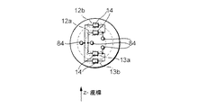
図8には、それぞれ薄壁状のダイヤフラム領域の縁部に配置された、複数の伸張測定エレメントが示されている。この場合、負のz方向で負荷が加えられると、領域12a,13b内の抵抗14が引張力にさらされ、また領域12b,13a内の抵抗14は、押圧力にさらされる。接続部84は測定評価に通じている。この場合も、伸張に基づく抵抗12a,12b,13a,13bは、ホイートストンブリッジに接続されている。
FIG. 8 shows a plurality of extension measuring elements, each arranged at the edge of a thin-walled diaphragm region. In this case, when a load is applied in the negative z direction, the
図9には、領域12a,13aだけを利用した別の変化例が示されている。この場合、抵抗14は、負のz方向の力が働くと、領域12a内では引張力として作用し、また領域13a内で押圧力として作用する。
FIG. 9 shows another variation example using only the
同様の配置は、領域12b若しくは13bでも可能である。これは図10に示されている。図10の実施例では、抵抗14は、力が負のz方向に働くと領域12b内で押圧力が作用し、領域13b内で引張力が作用する。
A similar arrangement is possible in the
凹部200は円形に形成されている。この場合、この円形形状の半径はどこでも同じである。変化実施例が図11に示されている。図11ではピン2がダイヤフラム3を介してスリーブ1に接続されている。測定信号を最適化するために、ピン2に向いた側の、部分円202の部分が、スリーブ1に向いた側の、部分円201の部分とは異なる、有利にはこの部分円201の部分よりも大きい半径を有している。このような形状によって、伸張測定エレメントの上記配置のために、伸張分布を、伸張測定エレメントの測定信号が力Fの作用に対して最大の感度で反応するように、適合させることができる。この部分円形状は、放物線状、スプライン曲線状(splinefoermig)又はその他の関数によっても近似的な若しくは最適なものが形成され得る。
The
力は固定端を介して導出される。 The force is derived through the fixed end.
これは図2に示されている。この場合、図1と同じ部材には同じ符号が用いられている。固定端23は、例えばねじ山付き部分17をねじ山にねじ込むことによって得られる。付加的に、図2aには旋回レバー(Schwinge)22が図示されている。この旋回レバー22は、力測定エレメントを断面した別の側面図(図2b)にも示されている。この旋回レバー22は、力を導入するために用いられる。この場合、旋回レバー22を介して力が導入され、固定端23を介して力が導出される。原則的に、固定端23と旋回アーム22とは交換することができる。旋回アームは、力測定エレメントのY軸線を中心にしたモーメントを解除する。
This is illustrated in FIG. In this case, the same reference numerals are used for the same members as in FIG. The
図2bは、図1に示した力測定エレメントのA−A線に沿った断面図を示しており、この場合、ピン2及び中間室21の隣に、段部19を備えたスリーブ1及び旋回レバー22が示されている。
FIG. 2 b shows a cross-sectional view along the line AA of the force measuring element shown in FIG. 1, in this case, next to the
図3aは、力測定エレメントを断面した側面図を示しており、この場合、同じ部材には御材符号が記されている。図3では、図2に示した実施例とは異なる構成の旋回レバー24及びスリーブ1が使用されている。スリーブは、旋回レバー24に回転方向32で必要な遊びを与えるために、自由室31を有している。
FIG. 3a shows a side view of a cross section of the force measuring element, in which case the same components are marked with a material code. In FIG. 3, the turning
すべての室軸線におけるモーメントを解除するための、図3a及び図3bに示した回転方向32は、例えば旋回レバー24における球面すり合わせジョイント25によって可能である。球面すり合わせジョイント25は、互いに係合し合う2つのエレメントより成っており、これえらのエレメントは、同じ中心点Mと同じ半径30とを有する(図3a参照)それぞれ1つの球状の表面25を備えている。旋回レバー24の球状の面は、内方に(中心点Mに)向いており、これに対して軸受26の球状の面は中心点Mから離れる方向で外方に向いている。2つの面は、回転運動を可能にするために、互いに僅かな遊びを有していてよい。
The direction of rotation 32 shown in FIGS. 3 a and 3 b for releasing the moments in all chamber axes is possible, for example, by means of a spherical sliding joint 25 in the swiveling
図3bは、図3aのA−A線に沿った断面図であって、この場合、ピン2だけが断面されていて、x、y、z軸線を中心にして球面すり合わせ25で可動な旋回レバー24のスリーブ1は正面図で示されている。
FIG. 3b is a cross-sectional view along the line AA in FIG. 3a, in which only the
一般的には、力が中間エレメントを介して力測定エレメントに導入される場合、この中間エレメントがジョイントとして構成されていれば、モーメントの解除が行われる。 Generally, when a force is introduced into a force measuring element via an intermediate element, the moment is released if the intermediate element is configured as a joint.
図4は、別の実施例の断面した側面図を示している。この実施例でも、ねじ山付き部分17が固定端23に螺合されている。ピン2は接合箇所10を介してダイヤフラム3に結合されていて、ダイヤフラム3は接合箇所11を介してスリーブ1に結合されている。この実施例では、ピン2に付加的にスペーサリング20が取り付けられており、このスペーサリング20は力制限部材として用いられる。スリーブ1に力が加えられることによって、間隔21が0に減少されると、力が制限される。何故ならば、それ以上の力が加えられることはなく、それ以上伸張することがないからである。この機能は、その他の図面において相応に選択された寸法によって実現される。このような構成では、接合箇所10及び11を省くことができ、力測定エレメントを1つの部材から簡単に製作することができるという利点が得られる。これは、スペーサリングを取り付ける前に、加工のために内室63に簡単にアクセス(接近)できるので、可能である。
FIG. 4 shows a cross-sectional side view of another embodiment. Also in this embodiment, the threaded
図5は、別の実施例の断面した側面図を示している。この実施例では、接合箇所11と接合箇所10とは、図4の実施例におけるように同一平面にあるのではなく、互いにずらして配置されている。オフセット(ずれ)50を設けたことによって、本発明による力測定エレメントをより容易に製作することができる。
FIG. 5 shows a cross-sectional side view of another embodiment. In this embodiment, the
図6には、ダイヤフラムとスリーブ60とが一体的に形成されている力測定エレメントが示されている。スリーブ60と、斜面61を備えたピン62とは、伸張に感応する領域を製作するために自由室63が内方へ変形されているように、成形されている。接合箇所10及び11は、スリーブつまりダイヤフラム60とピン62とを接続するために用いられる。
FIG. 6 shows a force measuring element in which the diaphragm and the
図7aは、本発明による力測定エレメントの別の実施例が示されている。この実施例ではリング状(環状)の2つの接合箇所10,11が設けられており、これらの接合箇所10,11によって、ダイヤフラム70をリング状に形成することができる。従ってピン72は表面が露出していて、またリング状のスリーブ71も表面が露出している。これによって、ダイヤフラム70のための材料つまり高張力鋼を節約することができる。図7bは、この実施例の断面した側面図を示している。この場合、リング状のダイヤフラム70とねじ山付き部分17とを備えた力測定エレメントは、固定端23に配属されている。
FIG. 7a shows another embodiment of a force measuring element according to the invention. In this embodiment, two ring-shaped (annular)
Claims (16)
ダイヤフラム(3)がピン(2)に結合されており、
ピン(2)に対するスリーブ(1)の前記間隔(21)は、ダイヤフラム(3)が、ピン(2)の長手方向に対して直交する方向でスリーブ(1)に加えられる力成分に基づいて伸張せしめられるように構成されており、
力測定エレメントは、ダイヤフラム(3)内で伸張に感応する領域を規定するために、ダイヤフラム(3)内に凹部(200)が形成されるように構成されており、
力測定エレメントを断面した側面図で見て、前記凹部(200)が、円形に形成されている力測定エレメントにおいて、
力測定エレメントを断面した側面図で見て、前記凹部(200)が、第1の部分円形状(201)と第2の部分円形状(202)とを有しており、第1の部分円形状(201)が、第2の部分円形状(202)よりも小さい半径を有していることを特徴とする、力測定エレメント。 A force measuring element comprising a pin (2) and a diaphragm (3), the outer region of the diaphragm (3) being connected to a sleeve (1), the extension of the diaphragm (3) Sensors (14, 15, 16) are provided, and the sleeve (1) is spaced from the pin (2) ,
Diaphragm (3) is connected to pin (2),
The spacing (21) of the sleeve (1) relative to the pin (2) is extended based on the force component applied to the sleeve (1) by the diaphragm (3) in a direction perpendicular to the longitudinal direction of the pin (2). It is configured to be squeezed ,
The force measuring element is configured such that a recess (200) is formed in the diaphragm (3) in order to define a region sensitive to extension in the diaphragm (3),
In the force measuring element in which the concave portion (200) is formed in a circular shape when viewed in a side view of the cross section of the force measuring element,
When the force measuring element is seen in a sectional side view, the recess (200) has a first partial circular shape (201) and a second partial circular shape (202), and the first partial circle Force measuring element, characterized in that the shape (201) has a smaller radius than the second partial circular shape (202) .
Applications Claiming Priority (1)
| Application Number | Priority Date | Filing Date | Title |
|---|---|---|---|
| PCT/DE2004/001454 WO2006005273A1 (en) | 2004-07-07 | 2004-07-07 | Force sensing element |
Publications (3)
| Publication Number | Publication Date |
|---|---|
| JP2008505327A JP2008505327A (en) | 2008-02-21 |
| JP2008505327A5 JP2008505327A5 (en) | 2013-03-07 |
| JP5248856B2 true JP5248856B2 (en) | 2013-07-31 |
Family
ID=34958206
Family Applications (1)
| Application Number | Title | Priority Date | Filing Date |
|---|---|---|---|
| JP2007519601A Active JP5248856B2 (en) | 2004-07-07 | 2004-07-07 | Force measuring element |
Country Status (4)
| Country | Link |
|---|---|
| US (1) | US7819017B2 (en) |
| EP (1) | EP1807687B1 (en) |
| JP (1) | JP5248856B2 (en) |
| WO (1) | WO2006005273A1 (en) |
Families Citing this family (14)
| Publication number | Priority date | Publication date | Assignee | Title |
|---|---|---|---|---|
| JP5195451B2 (en) * | 2008-04-15 | 2013-05-08 | 株式会社デンソー | FUEL INJECTION DEVICE AND PRESSURE ACCUMULATION FUEL INJECTION SYSTEM USED FOR THE SAME |
| JP5815320B2 (en) * | 2011-07-28 | 2015-11-17 | テイ・エス テック株式会社 | Load measurement sensor mounting structure |
| JP5960514B2 (en) * | 2012-06-08 | 2016-08-02 | テイ・エス テック株式会社 | Mounting structure for mounting load measurement sensor |
| JP2013035524A (en) * | 2011-08-10 | 2013-02-21 | Ts Tech Co Ltd | Structure for mounting load measurement sensor |
| US9038487B2 (en) * | 2011-07-28 | 2015-05-26 | Ts Tech Co., Ltd. | Support structure for load measurement sensor |
| JP2013028269A (en) * | 2011-07-28 | 2013-02-07 | Ts Tech Co Ltd | Structure for mounting load measurement sensor |
| JP2013035525A (en) * | 2011-08-10 | 2013-02-21 | Ts Tech Co Ltd | Structure for mounting load measurement sensor |
| US20140224553A1 (en) * | 2011-08-10 | 2014-08-14 | Ts Tech Co., Ltd. | Load measurement sensor support structure |
| US8887585B2 (en) * | 2011-11-26 | 2014-11-18 | Tecsis Gmbh | Force-sensing device for measuring a traction-and/or pressure force load in structure |
| US8893557B2 (en) * | 2013-01-09 | 2014-11-25 | King Fahd University Of Petroleum And Minerals | Fastener tension monitoring system |
| US9297687B2 (en) * | 2013-05-17 | 2016-03-29 | Sensata Technologies, Inc. | Sense element having a stud fitted within the sense element |
| US9429485B1 (en) * | 2015-03-12 | 2016-08-30 | The United States Of America As Represented By The Secretary Of The Navy | Bolt shear force sensor |
| CN110133329B (en) * | 2019-05-10 | 2021-10-01 | 江苏塔菲尔新能源科技股份有限公司 | Test fixture |
| WO2023177900A2 (en) * | 2022-03-17 | 2023-09-21 | Sensata Technologies, Inc. | Brake pedal with force sensor and membranes |
Family Cites Families (22)
| Publication number | Priority date | Publication date | Assignee | Title |
|---|---|---|---|---|
| US3812758A (en) * | 1972-10-24 | 1974-05-28 | Kaman Aerospace Corp | Bolt head which measures and maintains preload |
| JPS5687195A (en) * | 1979-12-19 | 1981-07-15 | Hitachi Ltd | Differential pressure transmitter |
| JPS60239630A (en) * | 1984-05-14 | 1985-11-28 | Yamato Scale Co Ltd | Weighing machine |
| JPS61184930A (en) | 1985-02-13 | 1986-08-18 | Nec Corp | Error correction coder |
| JPS61184930U (en) * | 1985-05-08 | 1986-11-18 | ||
| JPH0439553Y2 (en) * | 1986-10-17 | 1992-09-16 | ||
| JPH01253622A (en) * | 1988-04-01 | 1989-10-09 | Kyowa Electron Instr Co Ltd | Diaphragm type load transducer |
| US4823606A (en) * | 1988-06-23 | 1989-04-25 | Carron & Company | Diaphragm transducer for sensing loading |
| JPH0387622A (en) * | 1989-08-30 | 1991-04-12 | Nec Corp | Force sensor and its manufacture |
| US5094109A (en) * | 1990-12-06 | 1992-03-10 | Rosemount Inc. | Pressure transmitter with stress isolation depression |
| JP3275116B2 (en) * | 1993-06-11 | 2002-04-15 | ニッタ株式会社 | Force / moment sensor |
| JP3268128B2 (en) * | 1994-06-21 | 2002-03-25 | 本田技研工業株式会社 | Load sensor |
| JP3616838B2 (en) * | 1997-02-14 | 2005-02-02 | 丸宗工業株式会社 | Bearing with load cell |
| LU90287B1 (en) | 1998-09-16 | 2000-03-17 | Iee Sarl | Motor vehicle seat with integrated occupancy detection |
| JP4423650B2 (en) * | 1999-10-28 | 2010-03-03 | 丸宗工業株式会社 | Load detecting device in lifting device and lifting device provided for the same |
| DE19960786A1 (en) * | 1999-12-16 | 2001-06-21 | Schenck Process Gmbh | Radial force sensor for crane load or level detection, has flexible ring with resistance strain gauge arranged between force conducting elements and force sensing elements |
| DE10012983C2 (en) | 2000-03-16 | 2002-01-31 | Helmut Kulisch | Force-torque sensor |
| DE10023302C2 (en) * | 2000-05-15 | 2003-11-13 | Grieshaber Vega Kg | Piezoelectric excitable vibrating element |
| JP4108425B2 (en) * | 2002-09-25 | 2008-06-25 | 株式会社共和電業 | Welding type waterproof strain gauge and manufacturing method thereof |
| US7021159B2 (en) * | 2002-09-30 | 2006-04-04 | The Gates Corporation | Transducer |
| US20070234811A1 (en) * | 2006-04-05 | 2007-10-11 | Vega Grieshaber Kg | Vibrating sensor |
| US7520174B2 (en) * | 2006-08-24 | 2009-04-21 | Ronald C. Clarke | Method and apparatus for indicating a load |
-
2004
- 2004-07-07 US US10/563,443 patent/US7819017B2/en not_active Expired - Fee Related
- 2004-07-07 EP EP04762352.5A patent/EP1807687B1/en not_active Expired - Fee Related
- 2004-07-07 WO PCT/DE2004/001454 patent/WO2006005273A1/en active Application Filing
- 2004-07-07 JP JP2007519601A patent/JP5248856B2/en active Active
Also Published As
| Publication number | Publication date |
|---|---|
| US20080202225A1 (en) | 2008-08-28 |
| JP2008505327A (en) | 2008-02-21 |
| EP1807687A1 (en) | 2007-07-18 |
| EP1807687B1 (en) | 2017-09-13 |
| WO2006005273A1 (en) | 2006-01-19 |
| US7819017B2 (en) | 2010-10-26 |
Similar Documents
| Publication | Publication Date | Title |
|---|---|---|
| JP5248856B2 (en) | Force measuring element | |
| JP4104173B2 (en) | Multi-axis load cell | |
| US6915709B2 (en) | Force detection device | |
| US5513536A (en) | Pressure, force and torque measuring device | |
| WO2013185597A1 (en) | Force sensor including sensor plate with local differences in stiffness | |
| JP2017116281A (en) | Crank arm assembly | |
| JP2017194467A (en) | Method of manufacturing pressure sensor | |
| JP4656813B2 (en) | Multi-axis load cell | |
| JP4886752B2 (en) | Force measuring element | |
| JP2008505327A5 (en) | ||
| US5295399A (en) | Force moment sensor | |
| US10451507B2 (en) | Pressure sensor | |
| WO2015155956A1 (en) | Strain sensor and load detector using same | |
| JPH0221231A (en) | Load converter equipped with pedestal | |
| JP2650058B2 (en) | Force detection device | |
| US7437943B2 (en) | Force measurement element | |
| US7852191B2 (en) | Sensor and manufacturing method thereof | |
| JP4347165B2 (en) | Multi-axis force sensor | |
| JP3652041B2 (en) | Compound sensor | |
| KR20220020888A (en) | Apparatus and method for simultaneous detection of tangential and vertical forces acting at a detection point in a brake caliper or suspension of a vehicle wheel | |
| CN102538919B (en) | Force sensor structure | |
| JPH0461289B2 (en) | ||
| JP2020085628A (en) | Pressure sensor element and pressure sensor | |
| JPH0194234A (en) | Load converter | |
| JPH04110775A (en) | Three-dimensional measuring instrument for fluid velocity and flowing direction |
Legal Events
| Date | Code | Title | Description |
|---|---|---|---|
| A131 | Notification of reasons for refusal |
Free format text: JAPANESE INTERMEDIATE CODE: A131 Effective date: 20100617 |
|
| A601 | Written request for extension of time |
Free format text: JAPANESE INTERMEDIATE CODE: A601 Effective date: 20100916 |
|
| A602 | Written permission of extension of time |
Free format text: JAPANESE INTERMEDIATE CODE: A602 Effective date: 20100927 |
|
| A601 | Written request for extension of time |
Free format text: JAPANESE INTERMEDIATE CODE: A601 Effective date: 20101018 |
|
| A602 | Written permission of extension of time |
Free format text: JAPANESE INTERMEDIATE CODE: A602 Effective date: 20101025 |
|
| A601 | Written request for extension of time |
Free format text: JAPANESE INTERMEDIATE CODE: A601 Effective date: 20101116 |
|
| A602 | Written permission of extension of time |
Free format text: JAPANESE INTERMEDIATE CODE: A602 Effective date: 20101124 |
|
| A521 | Written amendment |
Free format text: JAPANESE INTERMEDIATE CODE: A523 Effective date: 20101214 |
|
| A131 | Notification of reasons for refusal |
Free format text: JAPANESE INTERMEDIATE CODE: A131 Effective date: 20110602 |
|
| A601 | Written request for extension of time |
Free format text: JAPANESE INTERMEDIATE CODE: A601 Effective date: 20110901 |
|
| A602 | Written permission of extension of time |
Free format text: JAPANESE INTERMEDIATE CODE: A602 Effective date: 20110908 |
|
| A601 | Written request for extension of time |
Free format text: JAPANESE INTERMEDIATE CODE: A601 Effective date: 20110930 |
|
| A602 | Written permission of extension of time |
Free format text: JAPANESE INTERMEDIATE CODE: A602 Effective date: 20111007 |
|
| A601 | Written request for extension of time |
Free format text: JAPANESE INTERMEDIATE CODE: A601 Effective date: 20111102 |
|
| A602 | Written permission of extension of time |
Free format text: JAPANESE INTERMEDIATE CODE: A602 Effective date: 20111114 |
|
| A521 | Written amendment |
Free format text: JAPANESE INTERMEDIATE CODE: A523 Effective date: 20111201 |
|
| A02 | Decision of refusal |
Free format text: JAPANESE INTERMEDIATE CODE: A02 Effective date: 20120914 |
|
| A524 | Written submission of copy of amendment under section 19 (pct) |
Free format text: JAPANESE INTERMEDIATE CODE: A524 Effective date: 20130115 |
|
| A911 | Transfer to examiner for re-examination before appeal (zenchi) |
Free format text: JAPANESE INTERMEDIATE CODE: A911 Effective date: 20130122 |
|
| TRDD | Decision of grant or rejection written | ||
| A01 | Written decision to grant a patent or to grant a registration (utility model) |
Free format text: JAPANESE INTERMEDIATE CODE: A01 Effective date: 20130313 |
|
| A61 | First payment of annual fees (during grant procedure) |
Free format text: JAPANESE INTERMEDIATE CODE: A61 Effective date: 20130411 |
|
| R150 | Certificate of patent or registration of utility model |
Ref document number: 5248856 Country of ref document: JP Free format text: JAPANESE INTERMEDIATE CODE: R150 Free format text: JAPANESE INTERMEDIATE CODE: R150 |
|
| FPAY | Renewal fee payment (event date is renewal date of database) |
Free format text: PAYMENT UNTIL: 20160419 Year of fee payment: 3 |
|
| R250 | Receipt of annual fees |
Free format text: JAPANESE INTERMEDIATE CODE: R250 |
|
| R250 | Receipt of annual fees |
Free format text: JAPANESE INTERMEDIATE CODE: R250 |
|
| R250 | Receipt of annual fees |
Free format text: JAPANESE INTERMEDIATE CODE: R250 |
|
| R250 | Receipt of annual fees |
Free format text: JAPANESE INTERMEDIATE CODE: R250 |
|
| R250 | Receipt of annual fees |
Free format text: JAPANESE INTERMEDIATE CODE: R250 |