JP5244282B2 - Improved metal frame for electronics and flat panel displays - Google Patents
Improved metal frame for electronics and flat panel displays Download PDFInfo
- Publication number
- JP5244282B2 JP5244282B2 JP2003514366A JP2003514366A JP5244282B2 JP 5244282 B2 JP5244282 B2 JP 5244282B2 JP 2003514366 A JP2003514366 A JP 2003514366A JP 2003514366 A JP2003514366 A JP 2003514366A JP 5244282 B2 JP5244282 B2 JP 5244282B2
- Authority
- JP
- Japan
- Prior art keywords
- amorphous alloy
- metal frame
- solidified amorphous
- bulk
- bulk solidified
- Prior art date
- Legal status (The legal status is an assumption and is not a legal conclusion. Google has not performed a legal analysis and makes no representation as to the accuracy of the status listed.)
- Expired - Lifetime
Links
Images


Classifications
-
- C—CHEMISTRY; METALLURGY
- C22—METALLURGY; FERROUS OR NON-FERROUS ALLOYS; TREATMENT OF ALLOYS OR NON-FERROUS METALS
- C22C—ALLOYS
- C22C45/00—Amorphous alloys
- C22C45/10—Amorphous alloys with molybdenum, tungsten, niobium, tantalum, titanium, or zirconium or Hf as the major constituent
-
- C—CHEMISTRY; METALLURGY
- C22—METALLURGY; FERROUS OR NON-FERROUS ALLOYS; TREATMENT OF ALLOYS OR NON-FERROUS METALS
- C22C—ALLOYS
- C22C33/00—Making ferrous alloys
- C22C33/003—Making ferrous alloys making amorphous alloys
-
- C—CHEMISTRY; METALLURGY
- C22—METALLURGY; FERROUS OR NON-FERROUS ALLOYS; TREATMENT OF ALLOYS OR NON-FERROUS METALS
- C22C—ALLOYS
- C22C45/00—Amorphous alloys
- C22C45/02—Amorphous alloys with iron as the major constituent
-
- H—ELECTRICITY
- H05—ELECTRIC TECHNIQUES NOT OTHERWISE PROVIDED FOR
- H05K—PRINTED CIRCUITS; CASINGS OR CONSTRUCTIONAL DETAILS OF ELECTRIC APPARATUS; MANUFACTURE OF ASSEMBLAGES OF ELECTRICAL COMPONENTS
- H05K5/00—Casings, cabinets or drawers for electric apparatus
- H05K5/02—Details
-
- H—ELECTRICITY
- H05—ELECTRIC TECHNIQUES NOT OTHERWISE PROVIDED FOR
- H05K—PRINTED CIRCUITS; CASINGS OR CONSTRUCTIONAL DETAILS OF ELECTRIC APPARATUS; MANUFACTURE OF ASSEMBLAGES OF ELECTRICAL COMPONENTS
- H05K5/00—Casings, cabinets or drawers for electric apparatus
- H05K5/04—Metal casings
-
- Y—GENERAL TAGGING OF NEW TECHNOLOGICAL DEVELOPMENTS; GENERAL TAGGING OF CROSS-SECTIONAL TECHNOLOGIES SPANNING OVER SEVERAL SECTIONS OF THE IPC; TECHNICAL SUBJECTS COVERED BY FORMER USPC CROSS-REFERENCE ART COLLECTIONS [XRACs] AND DIGESTS
- Y10—TECHNICAL SUBJECTS COVERED BY FORMER USPC
- Y10T—TECHNICAL SUBJECTS COVERED BY FORMER US CLASSIFICATION
- Y10T428/00—Stock material or miscellaneous articles
- Y10T428/30—Self-sustaining carbon mass or layer with impregnant or other layer
Abstract
Description
発明の分野
本発明は電子機器用の改良された金属フレームに関し、特に、FeおよびZr基のバルク凝固アモルファス合金およびバルク凝固アモルファス合金複合材料に関する。
FIELD OF THE INVENTION This invention relates to improved metal frames for electronic devices, and more particularly to Fe and Zr based bulk solidified amorphous alloys and bulk solidified amorphous alloy composites.
発明の背景
従来の電子装置は機能面で便宜的に2つの部分に分割できる。すなわち、電子装置の本来の機能を持つ電子部分と、この電子部分を機械的に保護する外殻フレームである。最良の保護は、電子装置の作動部品(1個または複数個のマイクロプロセッサ、メモリー装置、ストーレッジ装置など)をフレームで機械的に封入してしまうもので、例えば携帯用コンピュータ、パーソナルデータアシスタント(PDA)、携帯電話などがある。
BACKGROUND OF THE INVENTION Conventional electronic devices can be divided into two parts for convenience in function. That is, an electronic part having an original function of the electronic device and an outer frame for mechanically protecting the electronic part. The best protection is to mechanically enclose the working parts of the electronic device (one or more microprocessors, memory devices, storage devices, etc.) in a frame, for example a portable computer, personal data assistant (PDA). ) And mobile phones.
例えば、携帯型パソコン(一般にノート型パソコンと言われる)の場合、上部ケースと下部ケースとから成るハウジングが、画面(スクリーン)、コンピュータ本体、インタフェス装置を支持し収容している。典型的には、このハウジングはコンピュータを構成する種々の部品を一緒に固定するための搭載構造体でもある。ロジックボードやディスクドライブと言った種々の部品が上部ケースや下部ケースにネジなどの締結手段を用いて取り付けられる。電磁干渉(EMI)に対する保護のため、ハウジングの上下両ケース内に遮蔽材料のシートを配置したり、対象部品を金属構造物で取り囲んだりして、周囲の影響から隔離する。典型的なノートパソコンケースなどの携帯電子装置ケースの作製に際しては、全体を軽量化しつつ、装置の処理能力、メモリー容量、耐衝撃性を高める努力がなされている。 For example, in the case of a portable personal computer (generally referred to as a notebook personal computer), a housing composed of an upper case and a lower case supports and accommodates a screen, a computer body, and an interface device. Typically, this housing is also a mounting structure for securing together the various components that make up the computer. Various parts such as a logic board and a disk drive are attached to the upper case and the lower case using fastening means such as screws. In order to protect against electromagnetic interference (EMI), a sheet of shielding material is placed in the upper and lower cases of the housing, and the target part is surrounded by a metal structure to isolate it from the surrounding influences. In making a portable electronic device case such as a typical notebook computer case, efforts are being made to increase the processing capacity, memory capacity, and impact resistance of the device while reducing the overall weight.
この目的を達成するために、多数の設計要素が利用されている。まず、電子装置の小型化には、電子部品を小型化し、軽量の薄型パネルディスプレーを組み込んでいる。次に、コンピュータの種々の部品を搭載しかつ衝撃から隔離するための構造体を最小限の寸法とし、そして実際には、典型的のハウジングは埋め込み成形補強材(molded-in reinforcement)、リブ、搭載用ボスを成形体の部品搭載用内側表面に備えている。典型的には、ノートパソコン内の種々の回路基板は、埋め込み成形されたボスやリブに直接ネジ止めされている。最後に、装置の軽量化のために、ほとんどの場合、ハウジングケースは軽量高剛性のプラスチックや複合材料で作製される。 A number of design elements are utilized to achieve this goal. First, electronic devices are miniaturized by miniaturizing electronic components and incorporating lightweight thin panel displays. Next, the structure for mounting the various components of the computer and isolating it from the impact is minimized and, in practice, a typical housing is molded-in reinforcement, ribs, A mounting boss is provided on the inner surface for mounting the component of the molded body. Typically, various circuit boards in a notebook personal computer are screwed directly to embedded bosses or ribs. Finally, in order to reduce the weight of the device, the housing case is almost always made of a lightweight and highly rigid plastic or composite material.
上記のような携帯コンピュータ製造法は実用性が高いが、なお改良の余地がある。例えば、材料の観点では、プラスチックや複合材料は、軽量であるし、大部分の電子機器ケースに要求される複雑な形状への成形も容易であるが、金属に比べて構造的な強度や耐久性が一般に不十分である。また、金属ではなくプラスチックや複合材料を用いた場合、ケースと電子部品との間に別個のEMI保護層を設けなくてはならない。 Although the above-described portable computer manufacturing method is highly practical, there is still room for improvement. For example, in terms of materials, plastics and composite materials are lightweight and can be easily molded into complex shapes required for most electronic device cases, but they are structurally strong and durable compared to metals. Sex is generally insufficient. Further, when plastic or composite material is used instead of metal, a separate EMI protective layer must be provided between the case and the electronic component.
しかし、ケース全体を金属で作製すると重量やコストが増加して、軍事用途のような特殊な場合以外は実用的でない。例えば、プラスチックケースに伴う強度と耐久性の問題を解消するために、携帯コンピュータの上下ケースをダイキャスト金属で作製する試みが行なわれている。これにより確かに強度および耐久性は高まるが、重量が携帯には適さず、コストも高い。また、種々の補助部材をシート金属で作製した例もあるが、期待したような強度向上は得られていない。その上、従来の金属は大部分が成形性不足である。 However, if the entire case is made of metal, the weight and cost increase, which is not practical except for special cases such as military use. For example, in order to eliminate the strength and durability problems associated with plastic cases, attempts have been made to make the upper and lower cases of portable computers with die-cast metal. This certainly increases the strength and durability, but the weight is not suitable for carrying and the cost is high. In addition, there are examples in which various auxiliary members are made of sheet metal, but the strength improvement as expected is not obtained. In addition, most conventional metals are inadequate formability.
近年、マグネシウム合金の軽量と高強度に着目した研究が進められている。しかし、マグネシウム合金は従来からあるAl基合金などと比べて塑性加工性が非常に劣る。そのため現状では、マグネシウム合金は通常はダイキャストで製造されている。しかし、マグネシウム合金は薄肉製品のダイキャストが極めて難しいため、まだ比較的肉厚の製品に限られている。その上、マグネシウム合金鋳物には、鋳物にとって致命的とも言える気孔などの鋳造欠陥や酸化物系などの介在物が含まれて、これが表面に露出することがある。鋳造欠陥や介在物は、マグネシウム合金鋳物の機械強度を劣化させるし、表面に露出していると耐食性や外観に悪影響を及ぼす。 In recent years, research focusing on the light weight and high strength of magnesium alloys has been underway. However, the magnesium alloy is extremely inferior in plastic workability as compared with conventional Al-based alloys. Therefore, at present, magnesium alloys are usually manufactured by die casting. However, since magnesium alloy is extremely difficult to die cast thin products, it is still limited to relatively thick products. In addition, the magnesium alloy casting contains casting defects such as pores which can be fatal to the casting and inclusions such as oxides, which may be exposed on the surface. Casting defects and inclusions deteriorate the mechanical strength of the magnesium alloy casting, and if it is exposed on the surface, it adversely affects the corrosion resistance and appearance.
また、マグネシウム合金鍛造材やその他の混成結晶性合金材料は耐食性が向上するかもしれないし、軽量フレームでかつ従来の金属と同等の機械強度を持つかもしれないが、これらの金属では弾性限界(材料が塑性変形しないで弾性変形できる能力)について全く考慮が払われて来なかった。結果として、一般に電子機器用のケースは弾性限界が非常に低い金属で作られており、応力によるエネルギーを蓄える能力が低く、変形要因となる応力が負荷されたときに永久変形を起こし易い。 Magnesium alloy forgings and other hybrid crystalline alloy materials may have improved corrosion resistance and may be lightweight frames and have the same mechanical strength as conventional metals, but these metals have an elastic limit (material However, no consideration has been given to the ability to be elastically deformed without plastic deformation. As a result, a case for an electronic device is generally made of a metal having a very low elastic limit, has a low ability to store energy due to stress, and easily undergoes permanent deformation when stress that causes deformation is applied.
前述の背景から、携帯型電子機器の重量や製造コストを上昇させずに、構造体としての堅牢性や耐久性を高めた電子機器用ケースが求められている。 In view of the above-described background, there is a need for an electronic device case that has improved robustness and durability as a structure without increasing the weight and manufacturing cost of the portable electronic device.
発明の概要
本発明は、約1.5%以上、望ましくは約2.0%以上の弾性限界を含めて物理的機械的性質を改善した電子機器用金属フレームであり、望ましくは、Zr/TiまたはFe基のバルク凝固アモルファス合金およびバルク凝固アモルファス合金複合材料で少なくとも一部が作製されている高成形性の金属フレームである。
SUMMARY OF THE INVENTION The present invention is a metal frame for electronic devices with improved physical and mechanical properties including an elastic limit of about 1.5% or more, preferably about 2.0% or more, preferably Zr / Ti. Alternatively, it is a highly formable metal frame that is at least partially made of a Fe-based bulk solidified amorphous alloy and a bulk solidified amorphous alloy composite material.
一実施形態においては、バルク凝固アモルファス合金は、それぞれ原子%でa=30〜75、b=5〜60、c=0〜50である分子式(Zr、Ti)a(Ni、Cu、Fe)b(Be、Al、Si、B)cで表される合金群から選択される。もう1つの実施形態においては、他の遷移金属、望ましくはNb、Cr、V、Coを20原子%以下含有してよい。 In one embodiment, the bulk solidified amorphous alloy has a molecular formula (Zr, Ti) a (Ni, Cu, Fe) b where a = 30-75, b = 5-60, and c = 0-50, respectively, in atomic percent. (Be, Al, Si, B) Selected from the alloy group represented by c . In another embodiment, other transition metals, desirably Nb, Cr, V, Co may be contained in an amount of 20 atomic% or less.
別の実施形態においては、合金群は原子%でa=40〜75、b=5〜50、c=5〜50である分子式(Zr、Ti)a(Ni、Cu)b(Be)cで表される。別の実施形態においては、アモルファス合金の複合材料を用いて所望の剛性、耐衝撃性、熱伝導性をフレームに付与する。この実施形態においては、剛性を高めるための補強材として、カーボンの繊維またはプリフォーム、SiCの繊維またはプリフォームを用いることができる。この実施形態においては、補強材は複合材料体積の20%〜80%であることが望ましい。別の実施形態においては、補強材の形状および方位を調整することにより、例えば金属フレームの長さ方向と幅方向について所望の性質(例えば弾性率)にすることができる。
In another embodiment, the alloy group has the molecular formula (Zr, Ti) a (Ni, Cu) b (Be) c with atomic percent a = 40-75, b = 5-50, c = 5-50. expressed. Another embodiment your information, desired stiffness using the composite material of amorphous alloy, impact resistance, imparting thermal conductivity to the frame. In this embodiment, carbon fibers or preforms, SiC fibers or preforms can be used as a reinforcing material for increasing rigidity . In this embodiment, the reinforcement is desirably 20% to 80% of the composite material volume. In another embodiment, by adjusting the shape and orientation of the reinforcing material, for example, a desired property (for example, elastic modulus) can be obtained in the length direction and the width direction of the metal frame.
別の実施形態においては、フレームの形状の調整により、剛性と柔軟性の組合せを向上できる。この実施形態においては、ハニカム状、波状などの望みの形状を用いることができる。 In another embodiment, the combination of stiffness and flexibility can be improved by adjusting the shape of the frame. In this embodiment, a desired shape such as a honeycomb shape or a wave shape can be used.
別の実施形態においては、金属フレームはプラスチック、アルミニウムなどのような他の材料で作られた部分を備えていても良い。 In other embodiments, the metal frame may comprise portions made of other materials such as plastic, aluminum, and the like.
別の実施形態においては、アモルファス合金は硬さの値が約4GPa以上、望ましくは5.5GPa以上となるように選択する。 In another embodiment, the amorphous alloy is selected to have a hardness value of about 4 GPa or more, desirably 5.5 GPa or more.
別の実施形態においては、アモルファス合金は降伏強度が約2GPa以上となるように選択する。 In another embodiment, the amorphous alloy is selected to have a yield strength of about 2 GPa or greater.
別の実施形態においては、アモルファス合金は破壊靭性が約10.81MPa√m(10ksi√in(ksi・inch 1/2))以上、望ましくは21.62MPa√m(20ksi√in(ksi・inch 1/2))以上となるように選択する。
In another embodiment, the amorphous alloy has a fracture toughness of about 10.81 MPa√m ( 10 ksi√in (ksi · inch 1/2 ) ) or more, preferably 21.62 MPa√m ( 20 ksi√in (ksi · inch 1). / 2)) is selected to be above.
別の実施形態においては、アモルファス合金は密度が6.5g/cc以下、望ましくは4.5g/cc以下となるように選択する。 In another embodiment, the amorphous alloy is selected to have a density of 6.5 g / cc or less, desirably 4.5 g / cc or less.
別の実施形態においては、アモルファス合金は少なくとも、弾性限界と、硬さ、降伏強度、破壊靭性、密度のうちの1種類との2種類の性質が前記の範囲内となるように選択する。 In another embodiment, the amorphous alloy is selected such that at least two properties, elastic limit and one of hardness, yield strength, fracture toughness, density, are within the above ranges.
別の実施形態においては、アモルファス合金は少なくとも、弾性限界と、硬さ、降伏強度、破壊靭性、密度のうちの2種類との3種類の性質が前記の範囲内となるように選択する。 In another embodiment, the amorphous alloy is selected such that at least three properties of at least the elastic limit and two of hardness, yield strength, fracture toughness, and density are within the above ranges.
別の実施形態においては、別の実施形態においては、本発明の金属フレームは金属フレームアセンブリを構成する少なくとも1つの部分を含む。フレームが2以上の部分で構成される実施形態においては、1つの部分が電子機器を収容し、もう1つの部分がフラットパネルディスプレーを収容する。この実施形態においては、金属フレームの各部分はボルト締結、クランプ締結、接着、リベット留め、溶接などの種々の接合方法により、個々の収容物を固定する。 In another embodiment, in another embodiment, the metal frame of the present invention includes at least one portion that constitutes a metal frame assembly. In embodiments where the frame is comprised of two or more parts, one part contains the electronics and the other part contains the flat panel display. In this embodiment, each part of the metal frame fixes the individual contents by various joining methods such as bolt fastening, clamp fastening, adhesion, riveting, and welding.
別の実施形態においては、アモルファス合金フレームは、衝撃や振動を減衰させるためにリブあるいは支持プラットフォームのような構造を備えるように設計することにより、ハードディスクドライブのような影響を受け易い部品を保護する。 In another embodiment, the amorphous alloy frame protects sensitive components such as hard disk drives by designing them with structures such as ribs or support platforms to dampen shocks and vibrations. .
別の実施形態においては、アモルファス合金および複合材料のフレーム設計を例えば1ミクロン以下の寸法で高度化する(機能的、人間工学的、意匠的に精緻に設計する)。 In another embodiment, the frame design of the amorphous alloy and composite material is enhanced, for example, with dimensions of 1 micron or less (designed with high functional, ergonomic, and design details).
別の実施形態においては、本発明はPDA、携帯電話、ノート型コンピュータ等の携帯用電子装置に特化して設計したフレームである。 In another embodiment, the present invention is a frame designed specifically for portable electronic devices such as PDAs, cell phones, notebook computers and the like.
別の実施形態においては、本発明はアモルファス合金の電子装置用フレームの製造方法である。この実施形態においては、アモルファス合金をそのガラス転移温度付近で鋳造あるいは成形することにより、細部まで再現させ、複雑な形状の金属ケースを実現する。 In another embodiment, the present invention is a method of manufacturing an amorphous alloy electronic device frame. In this embodiment, an amorphous alloy is cast or molded in the vicinity of its glass transition temperature to reproduce details and realize a metal case with a complicated shape.
別の実施形態においては、金属フレームをアモルファス合金および複合材料のシートからスタンピングおよび/または型成形により作製する。この実施形態においては、スタンピングおよび/または型成形はガラス転移温度付近で行なうことが望ましい。別の実施形態においては、金属フレームはアモルファス合金および複合材料のシートから例えば水ジェット、レーザ切断、放電加工のような機械加工や切断によって作製する。金属フレームは金属鋳型鋳造や金属含浸法(アモルファス合金複合材料の場合)などの種々の形態の鋳造法によっても作製できる。 In another embodiment, the metal frame is made by stamping and / or molding from a sheet of amorphous alloy and composite material. In this embodiment, stamping and / or molding is preferably performed near the glass transition temperature. In another embodiment, the metal frame is made from a sheet of amorphous alloy and composite material by machining or cutting, such as water jet, laser cutting, electrical discharge machining. The metal frame can also be produced by various forms of casting methods such as metal mold casting and metal impregnation method (in the case of an amorphous alloy composite material).
別の実施形態においては、金属フレームは機械加工、切断、スタンピング、型成形により種々のスロットと孔を具備し、電子機器、フラットパネルディスプレーの作動時に発生する熱の冷却効果を高める。この実施形態においては、金属フレームが機械加工、切断、スタンピング、型成形により種々のスロットと孔を具備することにより、内部音響システムおよびスピーカーのための性能も高められる。最後に、金属フレームが機械加工、切断、スタンピング、型成形により種々のスロットと孔を具備することにより、キーボード、マウス、トラックパッドなどの種々のアクセサリーやアタッチメントのためのスペースができる。 In another embodiment, the metal frame is provided with various slots and holes by machining, cutting, stamping, and molding to enhance the cooling effect of heat generated during the operation of electronic devices and flat panel displays. In this embodiment, the metal frame is provided with various slots and holes by machining, cutting, stamping, and molding, which also enhances the performance for the internal sound system and speaker. Finally, the metal frame is provided with various slots and holes by machining, cutting, stamping, and molding, thereby providing space for various accessories and attachments such as a keyboard, mouse, and trackpad.
発明の詳しい説明
本発明は、弾性限界が約1.5%以上、望ましくは約2.0%以上の材料で少なくとも一部が作られていて物理的機械的な性質を改良してある金属フレームに関し、望ましくは、Zr−TiまたはFe基のバルク凝固アモルファス合金またはバルク凝固アモルファス合金複合材料のような成形性の優れた材料で作られたフレームに関する。本明細書中ではこのフレームを電子機器用フレームまたはケース、あるいはバルク凝固アモルファスフレームまたはケースと呼称する。
DETAILED DESCRIPTION OF THE INVENTION The present invention is a metal frame having improved physical and mechanical properties, at least partially made of a material having an elastic limit of about 1.5% or more, preferably about 2.0% or more. Preferably, the present invention relates to a frame made of a formable material such as a Zr—Ti or Fe-based bulk solidified amorphous alloy or a bulk solidified amorphous alloy composite. In this specification, this frame is referred to as an electronic device frame or case, or a bulk solidified amorphous frame or case.
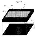
本発明の電子機器用フレームの代表例を図1〜5に示す。図示したように、金属フレーム10は、電子装置の部品40を収容する収容器20を壁部30が構成し、収容した部品40の操作に用いる開口部50を備えている。しかし、本発明の金属フレームは図1〜5に示したような基本的な部品を備えているが、ケース自体と、収容器および開口部の個数、寸法、形状と、収容されている電子機器部品の性質、形状、寸法とは、電子装置の性質に応じて多種多様である。例えば、本発明の金属フレームは、例えばPDAやノート型コンピュータのようなデータ蓄積装置や機械操作装置、ディジタルカメラやディジタルビデオカメラのようなマルチメディア記録装置、CDプレーヤーやDVDプレーヤーのようなマルチメディアプレーヤー、ポケベルや携帯電話のような伝達装置などの電子装置に用いることができる。
Representative examples of the electronic device frame of the present invention are shown in FIGS. As shown in the drawing, the
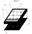
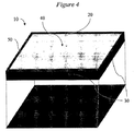
図1〜4は、種々の電子装置用に設計した金属フレームの実例である。例えば、図1のケース10は、キーボード40のようなユーザーインタフェス用の単一の開口部50を備えていて、設置型または携帯型のコンピュータの遠隔制御装置や部品としてのスタンドアローン装置といて用いられる。図2のケース10は、フラットパネルディスプレー40用とユーザーインタフェスまたはアクセスポート40’用に2つの開口部50を備えていて、DVDプレーヤー用や携帯型コンピュータの部品として用いられる。図3のケース10は携帯電話用またはPDAプレーヤー用で、2つの開口部50は1つがフラットパネルディスプレー40用でもう1つが1セットの制御ボタン40’用である。また、図4のケース10は、大きな単一の開口部50がフラットパネルテレビジョン用等のヴューパネルとして用いられる。
1-4 are examples of metal frames designed for various electronic devices. For example, the
図示したように、いずれの金属フレームも、種々の寸法・形状の収容器20と、種々の寸法・形状の壁部30と、種々の寸法・形状の電子部品40と、種々の寸法・形状の開口部50とを備えている。そして、図示の装置は開口部が2つ以下であるが、開口部の個数と位置は用途に依存するだけである。例えば、冷却用、保守用、種々の寸法・形状・個数のアクセサリ用の開口部を付加できる。
As shown in the figure, each metal frame has a
図1〜4のケースおよびフレームは、電子装置の作動部品を一体構造に収容してあるが、分離型または取付型の別体構造に収容することもできる。図5に示したのはその一例で、2つの部分を蝶番で連結した構造のケースである。このケースの一方の部分60はフラットパネルディスプレーを収容し、もう一方の部分70はユーザーインタフェス用または他の部品用である。
1-4, the operation parts of the electronic device are accommodated in an integral structure, but may be accommodated in a separate structure or a separate structure. FIG. 5 shows an example thereof, which is a case of a structure in which two parts are connected by a hinge. One
上記各ケースの組み立て工程の詳細は省略するが、フレームが2つ以上の部分から構成される場合(例えば図5の例)は、各部分同士の接合と内容物の固定は、ボルト締結、クランプ締結、接着、リベット締結、溶接などで行なうことができる。また、合金フレームがリブ、支持プラットフォームなどの構造を備えても良い。 Although the details of the assembly process of each case are omitted, when the frame is composed of two or more parts (for example, the example of FIG. 5), the joining of each part and the fixing of the contents are performed by bolt fastening and clamping. It can be performed by fastening, bonding, rivet fastening, welding or the like. The alloy frame may have a structure such as a rib or a support platform.
上記各図ではケースを前から見た斜視図のみで示したが、いずれの場合も金属フレームは反対側の端部や背面もカバーしている。また、5つの例のみを図示したが、本発明の金属フレームは、電子装置の電子部品を収容・保護するのに適した種々の形状・寸法とすることができる。例えば、携帯型コンピュータ用の金属フレームが米国特許第5,237,486号および第4,571,456号に開示されている(これらの開示内容は全て本発明の参考とした)。 In each of the above drawings, only the perspective view of the case seen from the front is shown, but in either case, the metal frame covers the opposite end and back. Although only five examples are shown, the metal frame of the present invention can have various shapes and dimensions suitable for housing and protecting the electronic components of the electronic device. For example, metal frames for portable computers are disclosed in US Pat. Nos. 5,237,486 and 4,571,456 (all of which are incorporated herein by reference).
図1〜5に示したケースおよびフレームは電子部品を収納する主収容器として設計されているが、これらの他に、本発明の電子機器フレームは、既に全体が収納された状態になっている電子装置を更に収納するのにも用いることができる。例えば、PDA、携帯電話、ノート型コンピュータのキャリングケースとして用いて装置を二重に保護することもできる。 Although the case and the frame shown in FIGS. 1 to 5 are designed as main containers for storing electronic components, in addition to these, the electronic device frame of the present invention is already stored in its entirety. It can also be used to further store electronic devices. For example, the device can be double protected by being used as a carrying case for PDAs, mobile phones, and notebook computers.
以上、本発明の電子機器フレームの構造、形状、機能に着目して説明した。しかし、発明の背景の項で述べたように、電子機器フレームの主な問題点はケースの耐久性とケース全体の重量との兼ね合いである。電子装置用のケースおよびフレームは、単位重要当りの耐久性がある程度以上必要であり、すなわちフレームは十分な保護機能を発揮しながら十分に軽量でなくてはならない。 As described above, the description has been given focusing on the structure, shape, and function of the electronic equipment frame of the present invention. However, as described in the background section of the invention, the main problem of the electronic equipment frame is a balance between the durability of the case and the weight of the entire case. Cases and frames for electronic devices are required to have a certain durability per unit criticality, that is, the frame must be sufficiently light while exhibiting a sufficient protection function.
ケースの耐久性を設定するに当って、フレーム材料を選定するための物理的なパラメータが多数ある。従来の電子機器フレームおよびケースの場合、技術者が材料選定で第一に考慮したのは、極限引張強さ(σUTS)すなわち材料が破断するまでに負荷される応力の最大値ができるだけ大きいと、そして弾性係数(荷重形態によってヤング率または曲げ弾性率)ができるだけ大きいことであった。更に、軽量フレームを作るための材料選定として、比極限引張強さ(密度に対する極限引張強さの比)ができるだけ大きいこと、そして、比弾性率(密度に対する弾性率の比)ができるだけ大きいことであった。これらの材料パラメータの主たる意味は、破断までに全体として負担できる最大荷重とフレーム全体の変形量である。しかし、破断までの負担可能な最大荷重およびフレーム全体としての変形量は個々のフレーム設計によって大きく変わり得る。 In setting the durability of the case, there are a number of physical parameters for selecting the frame material. In the case of the conventional electronic equipment frame and case, the engineer first considered in selecting the material is that the ultimate tensile strength (σ UTS ), that is, the maximum value of the stress applied until the material breaks is as large as possible. The elastic modulus (Young's modulus or flexural modulus depending on the load form) was as large as possible. Furthermore, as a material selection for making a lightweight frame, the specific ultimate tensile strength (ratio of ultimate tensile strength to density) is as large as possible, and the specific elastic modulus (ratio of elastic modulus to density) is as large as possible. there were. The main meanings of these material parameters are the maximum load that can be borne as a whole before breaking and the amount of deformation of the entire frame. However, the maximum load that can be borne up to breakage and the amount of deformation of the entire frame can vary greatly depending on the individual frame design.
例えば、同一材料・所定重量での変形を最小化するには中実棒よりもI形梁の方が有効である。したがって、必要な複雑形状に材料の成形・組み立てが可能なら、このような複雑な設計によって材料の構造的な短所を直ちに効果的に救済できる。 For example, I-shaped beams are more effective than solid bars to minimize deformation with the same material and a predetermined weight. Therefore, if it is possible to mold and assemble the material into the required complex shape, such a complicated design can immediately and effectively relieve the structural disadvantages of the material.
これらの性質は、フレームの負担できる最大荷重と、フレームが撓んだり変形したする能力の指標にはなるが、フレームの耐久性を十分に表すものではないし、押し付け、押し込み、突き刺し等の物理的外部作用による応力に対する部品保護の能力を十分に表すものでもない。また、これらのパラメータは、変形を生じさせる応力等による変形に対するケースの反応を十分に表すものでもない。もう1つ重要なのは、上述の設計的対処は選定した材料の物理的な欠点をある程度は補完できるが、耐久性の不足や、物理的外部作用に対する保護の不足を救済することはできない、という点である。 These properties are an indicator of the maximum load that the frame can bear and the ability of the frame to bend and deform, but do not fully represent the durability of the frame, and are not physical, such as pressing, pushing, and piercing. It also does not fully represent the ability to protect parts against stresses caused by external effects. Further, these parameters do not sufficiently represent the reaction of the case to deformation due to stress that causes deformation. Another important point is that the design measures described above can compensate for the physical shortcomings of the selected material to some extent, but cannot compensate for the lack of durability or the lack of protection against physical external effects. It is.
上述のような変形に対するケースの反応を説明するには、用いた材料の弾性限界(εf)を考慮する必要がある。弾性限界とは、材料が永久変形しないで物理的に変形できる量である。降伏強度と弾性限界との関係を図6の応力/歪曲線に模式的に示す。 To explain the case's response to deformation as described above, it is necessary to consider the elastic limit (ε f ) of the material used. The elastic limit is an amount by which a material can be physically deformed without being permanently deformed. The relationship between the yield strength and the elastic limit is schematically shown in the stress / strain curve of FIG.
電子機器用ケースの製造に対する材料の適性を決める際の弾性限界の重要性は、図7に最もよく表される。この図では、電子機器用ケースの製造に高級材料として頻繁に用いられている従来のTi合金のような高硬さ軽量材料と、本発明のバルク凝固材料とについて、応力/歪曲線を対比して示す。図示したように、従来材料は降伏点が比較的高いが、弾性限界が低ければ、軽微な変形も永久変形になる。これに対し、本発明のケースは降伏強度が高く、弾性変形量が大きくなっている。 The importance of the elastic limit in determining the suitability of a material for the manufacture of electronic device cases is best illustrated in FIG. In this figure, the stress / strain curve is compared between a high-hardness and lightweight material such as a conventional Ti alloy that is frequently used as a high-grade material in the manufacture of electronic device cases and the bulk solidified material of the present invention. Show. As shown in the figure, the conventional material has a relatively high yield point, but if the elastic limit is low, a slight deformation becomes a permanent deformation. In contrast, the case of the present invention has a high yield strength and a large amount of elastic deformation.
本発明によるケースの耐久性向上に果たす弾性限界の重要性は、図8の模式的曲線同士の比較により明示される。すなわち、図8に描いた2つの曲線下の面積は、落下とか打撃のような応力のエネルギーを弾性的に(永久損傷なしで)蓄積する能力を2種類の仮想材料について示したものである。図示のように、弾性限界が高い材料を選定すると、等しい降伏強度を持つ従来材料に比べて、遥かに大きいエネルギーを蓄積する(弾性変形しつつ)能力がある。そのため、本発明によって作製したケースは、弾性限界が1.5%以上の材料で形成され、それにより、使用中の永久変形や完全破壊し難くなっている。 The importance of the elastic limit for improving the durability of the case according to the present invention is clearly shown by comparing the schematic curves in FIG. That is, the areas under the two curves depicted in FIG. 8 show the ability of two types of virtual materials to store elastically (without permanent damage) the energy of stress such as dropping or striking. As shown in the figure, when a material having a high elastic limit is selected, it has an ability to store much larger energy (while elastically deforming) than a conventional material having the same yield strength. Therefore, the case produced according to the present invention is made of a material having an elastic limit of 1.5% or more, which makes it difficult to be permanently deformed or completely broken during use.
上述の性質は全て、材料の密度(ρ)すなわち体積当りの重量を考慮することにより更に明示できる。例えば、重量に対する降伏強度または弾性限界の比を用いて、本発明の電子機器用フレームとしてのアモルファス合金材料の適性を決めることができる。1つの有用な評価方法は密度に対する弾性限界の比であり、下式で定義される。 All of the above properties can be further manifested by considering the density (ρ) of the material, ie the weight per volume. For example, the suitability of the amorphous alloy material as an electronic device frame of the present invention can be determined using the ratio of the yield strength or elastic limit to the weight. One useful evaluation method is the ratio of elastic limit to density, defined by the following equation:
εf/ρ・・・・・・・・(1) ε f / ρ (1)
また、密度に対する降伏強度の比も上記の比と組み合わせて用いることができ、下式で表される。 Further, the ratio of yield strength to density can also be used in combination with the above ratio, and is expressed by the following equation.
σy /ρ・・・・・・・・・・(2)
σ y / ρ (2)
弾性限界比を用いて、望ましくは上記2つの比の組合せを用いて、適した材料の範囲を決定できる。 Using the elastic limit ratio, a suitable range of materials can be determined, preferably using a combination of the two ratios.
上記の望ましい機械的性質に加えて、電子機器用フレーム、特に使用環境・操作条件共に厳しい条件下に置かれる携帯型電子装置にとっては耐食性が非常に重要である。 In addition to the desirable mechanical properties described above, corrosion resistance is very important for electronic equipment frames, particularly for portable electronic devices that are subjected to harsh conditions both in the usage environment and operating conditions.
最後に、発明の背景の項で述べたように、金属製の電子機器フレームに関して次に重要な問題は、必要な複雑形状の物を効率良く製造することである。複雑形状物を製造するには、型成形と鋳造が最良であり、他の方法、例えば鍛造で製造した場合などは、後処理機械が必要になる。しかし、Al基合金等の従来材料の大部分は型成形性も鋳造性も低い。そのためケースおよびフレーム用に選択される材料は細密成形性を持たなくてはならない。 Finally, as mentioned in the Background section of the invention, the next most important problem with metallic electronic equipment frames is the efficient production of the necessary complex shapes. Molding and casting are best for producing complex shapes, and post-processing machines are required for other methods such as forging. However, most conventional materials such as Al-based alloys have low moldability and castability. Therefore, the material selected for the case and frame must have a fine formability.
材料の成形性は種々の方法で評価でき、例えば、ダイキャビティで再現可能な最小寸法、成形に要する成形温度や歪速度、最終製品の許容寸法公差で評価できる。 The formability of the material can be evaluated by various methods, for example, the minimum dimension reproducible by the die cavity, the molding temperature and strain rate required for molding, and the allowable dimension tolerance of the final product.
例えば、本発明の電子機器用ケースには細密寸法が必要なので、細密成形性を持つ材料だけが利用可能である。例えば、本発明の一実施形態においては、本発明の電子機器用フレームの形成に適しているのは、100ミクロンオーダで表面形態(模様、粗さ)を再現できる材料のみである。 For example, the electronic device case of the present invention requires a minute size, so that only a material having a fine formability can be used. For example, in one embodiment of the present invention, only materials capable of reproducing the surface morphology (pattern, roughness) on the order of 100 microns are suitable for forming the electronic device frame of the present invention.
適切な機械的耐久性、耐食性、成形性を得るために、本発明はバルク凝固アモルファス合金で作られた電子機器用フレームであり、特にZr−Ti基またはFe基のバルク凝固アモルファス合金で作られた電子機器フレームである。 In order to obtain appropriate mechanical durability, corrosion resistance, and formability, the present invention is an electronic device frame made of a bulk-solidified amorphous alloy, particularly made of a Zr-Ti-based or Fe-based bulk-solidified amorphous alloy. Electronic equipment frame.
バルク凝固アモルファス合金とは、500K/秒以下の遅い速度で冷却しても実質的にアモルファス構造が得られる合金群を指す。このようなバルク凝固アモルファス合金は厚さ0.5mm以上に製造できるものであり、これは最大鋳造可能厚さ0.020mmで冷却速度105K/秒以上を必要とした従来のアモルファス合金より遥かに厚い。更に、バルク凝固アモルファス合金の冷却速度が上記のように遅くてよいの、鋳造、型成形やプラスチック材料のような熱可塑鋳造などを含めて多種多様な方法で成形できる。 The bulk solidified amorphous alloy refers to a group of alloys that can substantially obtain an amorphous structure even when cooled at a slow rate of 500 K / second or less. Such a bulk solidified amorphous alloy can be manufactured to a thickness of 0.5 mm or more, which is far more than a conventional amorphous alloy that requires a maximum castable thickness of 0.020 mm and a cooling rate of 10 5 K / second or more. Thick. Furthermore, since the cooling rate of the bulk solidified amorphous alloy may be slow as described above, it can be formed by various methods including casting, mold forming, thermoplastic casting such as plastic material, and the like.
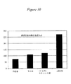
図9に示すように、バルク凝固アモルファス合金は弾性歪限界が1.5%以上であり、一般に2.0%程度である。比較として、従来の金属は弾性歪限界が0.6%以下である。前述したように、弾性歪限界は重要なファクターであり、弾性限界が高いと電子装置に対する拘束作用が大きくなる。例えば、電子機器ケースが落下したり打撃を受けたりした場合、周りを取り囲んでいる金属は引き伸ばされ、衝撃を蓄積して弾性的に反応する能力は、収容されている電子部品の永久損傷を防止する重要なファクターとなる。したがって、弾性限界が高いほど、電子機器ケースが内部の電子部品を安全に保持できる度合いが高まる。また、図10に示すように、バルク凝固アモルファス合金は降伏強度が1.6GPa以上であり、これは従来の金属より遥かに高い。材料の降伏強度が高いほど、損傷原因となる力に対して抵抗力が高まる。更に、バルク凝固アモルファス合金は、その固有の原子構造により、CD、DVD、標準ハードディスクドライブなどのデータ蓄積装置のように衝撃に影響され易い電子部品に対して、衝撃や振動を減衰させる作用がある。 As shown in FIG. 9, the bulk solidified amorphous alloy has an elastic strain limit of 1.5% or more, and is generally about 2.0%. As a comparison, the conventional metal has an elastic strain limit of 0.6% or less. As described above, the elastic strain limit is an important factor, and the higher the elastic limit, the greater the restraining action on the electronic device. For example, when an electronic device case falls or is hit, the surrounding metal is stretched and the ability to accumulate impact and react elastically prevents permanent damage to the contained electronic components It becomes an important factor to do. Therefore, the higher the elastic limit, the higher the degree that the electronic device case can safely hold the internal electronic components. Further, as shown in FIG. 10, the bulk solidified amorphous alloy has a yield strength of 1.6 GPa or more, which is much higher than that of the conventional metal. The higher the yield strength of the material, the greater the resistance to forces that cause damage. Furthermore, the bulk solidified amorphous alloy has an effect of attenuating impact and vibration on electronic components that are susceptible to impact, such as data storage devices such as CD, DVD, and standard hard disk drive, due to its unique atomic structure. .
すなわち、バルク凝固アモルファス合金はバルクアモルファス金属に特有の高降伏強度と高弾性限界との組合せにより、電子部品の収納体金属として非常に有用である。アモルファス合金を用いた具体例については、米国特許第5,288,344号、第5,368,659号、第5,618,359号、第5,735,975号に開示されている(これらの開示内容は全て本発明の参考とした)。 That is, the bulk solidified amorphous alloy is very useful as a metal body for electronic parts due to the combination of the high yield strength and high elastic limit specific to bulk amorphous metals. Specific examples using amorphous alloys are disclosed in U.S. Pat. Nos. 5,288,344, 5,368,659, 5,618,359, and 5,735,975. All of the disclosure content of was used as a reference for the present invention).
以上説明したように、電子機器用フレームとして形成された状態で弾性限界が約1.5%以上、望ましくは約2.0%以上であって、下記の物理特性すなわち約4GPa以上、望ましくは5.5GPa以上の硬さ、約2GPa以上の降伏強度、約10.81MPa√m(10ksi√in)以上、望ましくは21.62MPa√m(20ksi√in)以上の破壊靭性のうちから選択した少なくとも1つの物理特性を備えているバルク凝固アモルファス合金であれば本発明に用いることができる。
As described above, the elastic limit is about 1.5% or more, preferably about 2.0% or more when formed as a frame for electronic equipment, and has the following physical characteristics, that is, about 4 GPa or more, preferably 5 At least one selected from a hardness of 5 GPa or more, a yield strength of about 2 GPa or more, and a fracture toughness of about 10.81 MPa√m ( 10 ksi√in ) or more, preferably 21.62 MPa√m ( 20 ksi√in ) or more. Any bulk solidified amorphous alloy having two physical properties can be used in the present invention.
また、材料強度の対重量比を高めるために密度は約8.5g/cc以下とすべきである。すなわち、密度に対する降伏強度の比(式(1))は0.2以上が望ましく、密度に対する弾性限界の比(式(2))は0.17以上が望ましい。 Also, the density should be about 8.5 g / cc or less in order to increase the material strength to weight ratio. That is, the ratio of yield strength to density (formula (1)) is desirably 0.2 or more, and the ratio of elastic limit to density (formula (2)) is desirably 0.17 or more.
望ましい実施形態においては、上記特性のうち少なくとも2つと上記望ましい範囲内の弾性限界との組合せが得られるようにバルク凝固アモルファス合金を選定する。最も望ましい実施形態においては、上記特性のうち少なくとも3つと上記望ましい範囲内の弾性限界との組合せが得られるようにバルク凝固アモルファス合金またはバルク凝固アモルファス合金複合材料を選定する。 In a preferred embodiment, the bulk solidified amorphous alloy is selected to achieve a combination of at least two of the above properties and an elastic limit within the desired range. In the most preferred embodiment, the bulk solidified amorphous alloy or bulk solidified amorphous alloy composite is selected so as to obtain a combination of at least three of the above properties and an elastic limit within the desired range.
これらの特性は所望の電子機器ケースのタイプに応じて種々に組合せ可能である。例えば、望ましい実施形態においては、電子機器用金属フレームは弾性歪限界が1.5%以上の金属で作製される。別の実施形態では、ケースは弾性歪限界が1.5%以上でありかつ硬さが4GPa以上である金属製である。別の実施形態では、弾性歪限界が1.5%以上でありかつ硬さが5.5GPa以上である金属を用いる。更に別の実施形態では、弾性限歪限界が1.5%以上でありかつ破壊靭性が10.81MPa√m(10ksi√in)以上である金属を用いる。もう1つ別の実施形態では、弾性歪限界が1.5%以上でありかつ破壊靭性が21.62MPa√m(20ksi√in)以上である金属を用いる。更にもう1つ別の実施形態では、弾性歪限界が1.5%以上でありかつ降伏強度が2GPa以上である金属を用いる。
These characteristics can be combined in various ways depending on the type of electronic equipment case desired. For example, in a desirable embodiment, the metal frame for electronic devices is made of a metal having an elastic strain limit of 1.5% or more. In another embodiment, the case is made of metal having an elastic strain limit of 1.5% or more and a hardness of 4 GPa or more. In another embodiment, a metal having an elastic strain limit of 1.5% or more and a hardness of 5.5 GPa or more is used. In still another embodiment, a metal having an elastic limit strain limit of 1.5% or more and a fracture toughness of 10.81 MPa√m ( 10 ksi√in ) or more is used. In another embodiment, a metal having an elastic strain limit of 1.5% or more and a fracture toughness of 21.62 MPa√m ( 20 ksi√in ) or more is used. In still another embodiment, a metal having an elastic strain limit of 1.5% or more and a yield strength of 2 GPa or more is used.
複数の特性を必要とする実施形態においては、電子機器用金属フレームは弾性歪限界1.5%以上、硬さ4GPa以上、破壊靭性10.81MPa√m(10ksi√in)以上の金属か、または、弾性歪限界1.5%以上、硬さ5.5GPa以上、破壊靭性21.62MPa√m(20ksi√in)以上の金属で作製する。
In an embodiment requiring a plurality of characteristics, the metal frame for electronic equipment is a metal having an elastic strain limit of 1.5% or more, a hardness of 4 GPa or more, and a fracture toughness of 10.81 MPa√m ( 10 ksi√in ) or more, It is made of a metal having an elastic strain limit of 1.5% or more, a hardness of 5.5 GPa or more, and a fracture toughness of 21.62 MPa√m ( 20 ksi√in ) or more.
材料の密度を考慮する必要がある実施形態においては、電子機器用金属フレームは弾性限界が1.5%以上であり、密度が6.5g/cc以上または4.5g/cc以上である金属で作製する。 In an embodiment in which the density of the material needs to be taken into account, the metal frame for electronic equipment is a metal having an elastic limit of 1.5% or more and a density of 6.5 g / cc or more, or 4.5 g / cc or more. Make it.
要するに、電子機器用ケースには弾性限界1.5%以上の金属材料を用いる。また、望ましい実施形態においては、電子機器に用いる金属材料は硬さが4GPa以上、望ましくは5.5GPa以上である。より望ましい実施形態においては、金属材料は破壊靭性10.81MPa√m(10ksi√in)以上、更に望ましくは破壊靭性21.62MPa√m(20ksi√in)以上である。更に望ましい実施形態においては、金属材料は密度6.5g/cc以下である。これらはフレームの材質特性であって、金属フレームの構造特性ではない。バルク凝固アモルファス合金を用いることによって初めて本発明のこれら望ましい特性が得られる。
In short, a metal material having an elastic limit of 1.5% or more is used for the electronic device case. In a desirable embodiment, the metal material used for the electronic device has a hardness of 4 GPa or more, preferably 5.5 GPa or more. In a more desirable embodiment, the metal material has a fracture toughness of 10.81 MPa√m ( 10 ksi√in ) or more, and more preferably a fracture toughness of 21.62 MPa√m ( 20 ksi√in ) or more. In a more desirable embodiment, the metal material has a density of 6.5 g / cc or less. These are frame material properties, not metal frame structural properties. These desirable properties of the present invention are obtained only by using a bulk solidified amorphous alloy.
また、大部分の電子機器用フレームおよびケースには多種多様なコーナー部や角度付き部分があるため、アモルファス合金材料は長時間にわたって成形性を維持できなくてはならない。図11〜13に示すように、バルクアモルファス合金は融点以上からガラス転移温度に至る温度域で流動性を維持しているので、ガラス転移温度以下で大きな応力を蓄積することが無い。更に、バルクアモルファス合金の凝固収縮は従来金属の凝固収縮より遥かに小さい。上記の特性を備えているため、バルクアモルファス合金は、型成形でも鋳造でも、変形を生ぜずに、しかもコストのかかる成形後処理工程を必要とせずに、電子機器用ケースの非常に複雑な形状に成形できる。 Also, since most electronic equipment frames and cases have a wide variety of corners and angled parts, the amorphous alloy material must be able to maintain formability for a long time. As shown in FIGS. 11 to 13, since the bulk amorphous alloy maintains fluidity in a temperature range from the melting point to the glass transition temperature, no large stress is accumulated below the glass transition temperature. Furthermore, the solidification shrinkage of bulk amorphous alloys is much smaller than that of conventional metals. Because of the above characteristics, bulk amorphous alloys are extremely complex shapes for electronic equipment cases, without deformation and costly post-molding treatment steps, both in mold and casting. Can be molded.
すなわち、一実施形態においては、示差走査熱量測定(DSC:differential scanning calorimetry)で求めたΔTsc(過冷却液体領域)が30℃以上、望ましくは60℃以上、最も望ましくは90℃以上であり、材料がガラス転移範囲付近で長時間成形可能であるバルク凝固アモルファス合金のみを用いる。この実施形態では、「ガラス転移範囲付近」とは、成形操作がガラス転移より高温、ガラス転移点より僅かに低温、またはガラス転移点で、ただし結晶化温度Txより低温で可能である、という意味である。最終的な成形製品がアモルファス合金素材の高い弾性限界を維持できるように、型成形の温度と時間は下記の表1に示した最高温度(℃)に従って制限することが望ましい。 That is, in one embodiment, ΔTsc (supercooled liquid region) determined by differential scanning calorimetry (DSC) is 30 ° C. or higher, preferably 60 ° C. or higher, and most preferably 90 ° C. or higher. However, only bulk-solidified amorphous alloys that can be formed for a long time near the glass transition range are used. In this embodiment, “near the glass transition range” means that the molding operation can be performed at a temperature higher than the glass transition, slightly lower than the glass transition point, or a glass transition point, but lower than the crystallization temperature Tx. It is. It is desirable to limit the molding temperature and time according to the maximum temperature (° C.) shown in Table 1 below so that the final molded product can maintain the high elastic limit of the amorphous alloy material.

表中、Tmaxは型成形の最高許容温度、Tmax(Pr.)は望ましい最高許容温度、Tmax(M.Pr.)は最も望ましい最高許容温度である。 In the table, Tmax is the maximum allowable temperature for molding, Tmax (Pr.) Is the desired maximum allowable temperature, and Tmax (M.Pr.) is the most desirable maximum allowable temperature.
表中、Tg、Tsc、Txは標準DSC(20℃/分で走査)により求めた。Tgはガラス転移の開始温度、Tscは過冷却液体領域の開始温度、Txは結晶化の開始温度である。ΔTscはTxとTscとの差である。全て温度の単位は「℃」である。 In the table, Tg, Tsc and Tx were determined by standard DSC (scanned at 20 ° C./min). Tg is the glass transition start temperature, Tsc is the start temperature of the supercooled liquid region, and Tx is the crystallization start temperature. ΔTsc is the difference between Tx and Tsc. All units of temperature are “° C.”.
上述の機械特性、耐食性、成形性を備えたZr−Ti基のバルク凝固アモルファス合金群の1つは、下記分子式で表される。(Zr、Ti)a(Ni、Cu、Fe)b(Be、Al、Si、B)c、ここで原子%でaはほぼ30〜75の範囲内、bはほぼ5〜60の範囲内、cはほぼ0〜50の範囲内である。上記分子式はバルク凝固アモルファス合金の全種類を包含するものではない。例えば、上記バルク凝固アモルファス合金は他の遷移金属例えばNb、Cr、V、Coを総量で約20原子%まで含有できる。1つの典型的なバルク凝固アモルファス合金は分子式(Zr、Ti)a(Ni、Cu)b(Be)cで表され、原子%でaはほぼ40〜75の範囲内、bはほぼ5〜50の範囲内、cはほぼ5〜50の範囲内で表される。1つの典型的なバルク凝固アモルファス合金組成は、Zr41Ti14Ni10Cu12.5Be22.5である。更に望ましい組成は(Zr、Ti)a(Ni、Cu)b(Be)c、原子%でaはほぼ45〜65の範囲内、bはほぼ7.5〜35の範囲内、cはほぼ10〜37.5の範囲内である。もう1つ、BeZrTi基ではない望ましい合金群は、(Zr)a(Nb、Ti)b(Ni、Cu)c(Al)dで表され、原子%でaは45〜65の範囲内、bは0〜10の範囲内、cは20〜40の範囲内、dは7.5〜15の範囲内である。更に、上記ZrTi基バルク凝固アモルファス合金は非常に耐食性が高い。 One of the Zr—Ti based bulk solidification amorphous alloy groups having the above-mentioned mechanical properties, corrosion resistance, and formability is represented by the following molecular formula. (Zr, Ti) a (Ni, Cu, Fe) b (Be, Al, Si, B) c, where a is in the range of approximately 30-75 and b is in the range of approximately 5-60, in atomic%. c is in the range of approximately 0-50. The above molecular formula does not encompass all types of bulk solidified amorphous alloys. For example, the bulk solidified amorphous alloy may contain up to about 20 atomic% of other transition metals such as Nb, Cr, V, and Co. One typical bulk solidified amorphous alloy is represented by the molecular formula (Zr, Ti) a (Ni, Cu) b (Be) c, where a is in the range of approximately 40-75 and b is approximately 5-50. And c is represented in the range of approximately 5-50. One typical bulk-solidifying amorphous alloy composition is Zr 41 Ti 14 Ni 10 Cu 12.5 Be 22.5 . A more desirable composition is (Zr, Ti) a (Ni, Cu) b (Be) c, in atomic percent, a is in the range of about 45 to 65, b is in the range of about 7.5 to 35, and c is about 10 Within the range of ~ 37.5. Another desirable alloy group that is not based on BeZrTi is represented by (Zr) a (Nb, Ti) b (Ni, Cu) c (Al) d, where a is in the range of 45 to 65 in atomic%, b Is in the range of 0 to 10, c is in the range of 20 to 40, and d is in the range of 7.5 to 15. Furthermore, the ZrTi-based bulk solidified amorphous alloy has very high corrosion resistance.
もう1つ、本発明に適したバルク凝固アモルファス合金は鉄系金属(Fe、Ni、Co)基の組成である。その例として、米国特許第6,325,868号(A. Inoue et. al., Appl. Phys. Lett., volume 71, p 464(1997))、(Shen et al., Mater. Trans. JIM, volume 42, p 2136(2001))、および日本特許出願:特願2000-126277(特開2001-303218)に開示されている(これらの開示内容は本発明の参考とした)。これら合金の典型的な組成の一例はFe72Al5Ga2P11C5B4である。またもう1つ典型例はFe72Al7Zr10Mo5W2B15である。これらの合金はZr基合金に比べると成形性は低いが、厚さ0.5mm程度以上には成形できるので本発明に用いるには十分である。また、これらの合金の密度は6.5g/cc〜8.5g/ccと一般に大きいが、硬さが7.5GPa〜12GPa以上と高いので高耐摩耗性の必要な用途には特に魅力的である。同様に、これらの材料は弾性歪限界が1.2%以上、降伏強度が2.5GPa〜4GPaである。 Another bulk solidified amorphous alloy suitable for the present invention is a composition of an iron-based metal (Fe, Ni, Co) group. For example, US Pat. No. 6,325,868 (A. Inoue et. Al., Appl. Phys. Lett., Volume 71, p 464 (1997)), (Shen et al., Mater. Trans. JIM , volume 42, p 2136 (2001)), and Japanese Patent Application: Japanese Patent Application No. 2000-126277 (Japanese Patent Laid-Open No. 2001-303218) (the disclosures of which are incorporated herein by reference). An example of a typical composition of these alloys is Fe 72 Al 5 Ga 2 P 11 C 5 B 4 . Another typical example is Fe 72 Al 7 Zr 10 Mo 5 W 2 B 15 . These alloys are less formable than Zr-based alloys, but are sufficient for use in the present invention because they can be formed to a thickness of about 0.5 mm or more. The density of these alloys is generally high at 6.5 g / cc to 8.5 g / cc, but the hardness is as high as 7.5 GPa to 12 GPa, so it is particularly attractive for applications that require high wear resistance. is there. Similarly, these materials have an elastic strain limit of 1.2% or more and a yield strength of 2.5 GPa to 4 GPa.
Zr−Ti基およびFe基のバルク凝固アモルファス合金群は、その特有な物理的特性の組み合わせのため、本発明の電子機器用フレームの作製に適している。 The Zr—Ti-based and Fe-based bulk solidified amorphous alloys are suitable for producing the electronic device frame of the present invention because of their unique combination of physical properties.
図7〜図13に示したように、本発明のバルク凝固アモルファス合金は、永久変形も破断もせずに1.5%以上の歪を発揮でき、かつ/または、約10.81MPa√m(10ksi√in)以上、更には約21.62MPa√m(20ksi√in)以上の高い破壊靭性を発揮でき、かつ/または、約4GPa以上、更には約5.5GPa以上の高い硬さを発揮できる。従来の材料と比較すると、適したバルクアモルファス合金は降伏強度レベルが約2GPa以上に達し、現状のTi合金のレベルを超えている。 As shown in FIGS. 7 to 13, the bulk solidified amorphous alloy of the present invention can exhibit a strain of 1.5% or more without being permanently deformed or broken, and / or about 10.81 MPa√m ( 10 ksi √in ) or more, more preferably high fracture toughness of about 21.62 MPa√m ( 20 ksi√in ) or more, and / or high hardness of about 4 GPa or more, further about 5.5 GPa or more. Compared to conventional materials, suitable bulk amorphous alloys have a yield strength level of about 2 GPa or more, exceeding the level of current Ti alloys.
一般に、バルクアモルファス合金中に結晶が析出すると物理特性、特に靭性や強度にとって非常に有害なので、結晶質析出物の体積率は極力小さくすることが一般に望ましい。しかし、場合によってはバルクアモルファス合金の製造プロセスで延性のある金属結晶相がその場析出するが、延性析出物はバルクアモルファス合金の特性、特に靭性および延性に良い影響を及ぼすこともある。1つの典型例はC.C. Hays et al., Physical Review letters, vol. 84, p 2901, 2000に開示されている(この開示内容は本発明の参考とした)。 In general, when crystals are precipitated in a bulk amorphous alloy, it is very harmful to physical properties, particularly toughness and strength. Therefore, it is generally desirable to make the volume fraction of crystalline precipitates as small as possible. However, in some cases, a ductile metal crystal phase precipitates in-situ in the bulk amorphous alloy manufacturing process, but the ductile precipitate may have a positive effect on the properties of the bulk amorphous alloy, particularly toughness and ductility. One typical example is disclosed in C.C. Hays et al., Physical Review letters, vol. 84, p 2901, 2000 (the disclosure of which was incorporated herein by reference).
以上では純粋なバルクアモルファス合金を説明したが、例えばSiC、ダイアモンド、炭素繊維、モリブデン等の金属などの材料との複合材料として製造することもできる。バルクアモルファスマトリクス複合材料の形成に用いることができる方法は種々あり、溶湯含浸法や熱可塑成形法がある。バルクアモルファス金属の複合材料は米国特許第5,886,254号および第5,567,251号に開示されている(これらの開示内容は全て本発明の参考とした)。バルクアモルファスマトリクス複合材料は炭素繊維等の種々の補強材(強化材)を含有するので、機械特性を個々の要請に合致させることができる。例えば、補強材として炭素繊維を50vol%まで含有させると、密度が3.5g/ccまで低下し、弾性率は300GPaまで増加して、高い比合成率(ヤング率/密度)が得られる。この数値は、炭素繊維やSiC粒子または繊維などの材料をもっと高い体積率で含有させれば更に向上する。更に望ましくは、炭素繊維、SiC粒子、および他の金属例えばモリブデンを組合せたバルクアモルファス合金混合複合材料を作れば、曲げ強度5GPa以上で靭性および高強度を備えかつ3g/cc〜6g/ccという低密度の複合材料が得られる。この実施形態においては、補強材は複合材料の20vol%〜80vol%が望ましい。 Although a pure bulk amorphous alloy has been described above, it can also be manufactured as a composite material with a material such as SiC, diamond, carbon fiber, molybdenum, or the like. There are various methods that can be used for forming the bulk amorphous matrix composite material, and there are a melt impregnation method and a thermoplastic molding method. Bulk amorphous metal composites are disclosed in US Pat. Nos. 5,886,254 and 5,567,251, all of which are incorporated herein by reference. Since the bulk amorphous matrix composite material contains various reinforcing materials (reinforcing materials) such as carbon fibers, the mechanical properties can be matched to individual requirements. For example, when carbon fiber is contained up to 50 vol% as a reinforcing material, the density is reduced to 3.5 g / cc, the elastic modulus is increased to 300 GPa, and a high specific synthesis rate (Young's modulus / density) is obtained. This value is further improved if materials such as carbon fibers, SiC particles or fibers are contained at a higher volume ratio. More desirably, if a bulk amorphous alloy mixed composite material combining carbon fiber, SiC particles, and other metals such as molybdenum is made, the bending strength is 5 GPa or more, the toughness and the high strength are provided, and 3 g / cc to 6 g / cc is low. A composite material of density is obtained. In this embodiment, the reinforcing material is desirably 20 vol% to 80 vol% of the composite material.
以上では複合材料の作製方法の詳細は説明しなかったが、補強材の方位および形状は調整可能であり、例えば、金属フレームの長手方向および幅方向について所望特性(剛性など)を最適化するように補強材を配列することができる。また、複合材料の補強材料は、用途に応じて材料特性を調整するのに適した形状すなわち繊維状、粒子状、ウィスカ状およびその他の形状で供給される。 Although the details of the method for producing the composite material have not been described above, the orientation and shape of the reinforcing material can be adjusted, for example, so as to optimize desired characteristics (such as rigidity) in the longitudinal direction and the width direction of the metal frame. Reinforcing materials can be arranged on the surface. Further, the reinforcing material of the composite material is supplied in a shape suitable for adjusting the material characteristics according to the use, that is, in a fibrous shape, a particulate shape, a whisker shape, and other shapes.
バルク凝固アモルファス合金の金属フレームおよび複合材料は、ダイアモンド、TiN、SiCのような耐火高硬度材料を0.010mmまでの厚さに被覆することにより、更に高硬さとして耐久性を高めるように作製できる。バルク凝固アモルファス合金はこれらの薄い被覆の有効な下地となるので引っ掻き疵や欠け脱落に対する保護が向上する。 Bulk-solidified amorphous alloy metal frames and composites are made to further increase durability by coating refractory and hard materials such as diamond, TiN, and SiC to a thickness of up to 0.010 mm. it can. Bulk-solidified amorphous alloys provide an effective substrate for these thin coatings and thus improve protection against scratching and chipping.
また、金属フレームに意匠的あるいは色彩的な処理を更に施すこともできる。例えば、金属フレームに適当な電気化学的処理例えば陽極酸化(金属の電気化学的酸化)を施すことで青、紫などの所望の色を付与して意匠性を高めることができる。このような陽極酸化被膜自体に更に付加する(すなわち有機・無機の着色、潤滑剤など)ことができるので、陽極酸化処理した金属フレームに更に意匠的なあるいは機能的な処理を施すことができる。この実施形態においては、従来の陽極酸化処理方法を適宜利用できる。 Further, a design or color treatment can be further applied to the metal frame. For example, by applying an appropriate electrochemical treatment such as anodization (metal electrochemical oxidation) to the metal frame, a desired color such as blue or purple can be imparted to enhance the design. Since it can be further added to such an anodized film itself (that is, organic / inorganic coloring, lubricant, etc.), the anodized metal frame can be further subjected to a design or a functional treatment. In this embodiment, a conventional anodizing method can be used as appropriate.
以上では本発明の金属フレームへのバルク凝固アモルファス合金の適用に着目したが、金属フレームの他の部位の作製に従来材料を用いることもできる。例えば、フレームの内壁あるいは外壁にポリウレタン、ポリカーボネート、ポリアミド、ポリアミドコポリマーなどの熱可塑性材料の装飾層や保護層を1層または複数層施すこともできる。また、合成熱硬化性発泡体のフィラーコアを接着フィルムで囲んで金属フレームとその外側の装飾壁または保護壁との接着機能を付与することができる。 In the above, attention has been paid to the application of the bulk solidified amorphous alloy to the metal frame of the present invention, but conventional materials can also be used for the production of other parts of the metal frame. For example, one or more decorative layers or protective layers made of a thermoplastic material such as polyurethane, polycarbonate, polyamide, and polyamide copolymer can be applied to the inner wall or outer wall of the frame. In addition, the filler core of the synthetic thermosetting foam can be surrounded by an adhesive film to give an adhesion function between the metal frame and the outer decorative wall or protective wall.
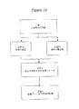
本発明は、バルク凝固アモルファス合金から電子機器用フレームを作製する方法をも提供する。図14は、本発明のバルク凝固アモルファス合金製品を形成するプロセスを示すフローチャートである。素材の準備工程(工程1)では、型成形の場合には素材はアモルファス状態の固体片であり、鋳造の場合には素材は融点より高温の合金溶湯である。次に、上記溶湯を融点以上の温度から所望形状に鋳造して冷却するか(工程2a)、上記固体の素材をガラス転移温度以上に加熱して所望形状に型成形する(工程2b)。本発明において鋳造方法は特に限定する必要はなく、永久鋳型鋳造法、ダイキャスト法、平坦流鋳造のような連続鋳造法を用いることができる。ダイキャスト法は米国特許第5,711,363号に開示されている(その開示内容は本発明の参考とした)。同様に、種々の型成形法を用いることができ、例えばブローモールディング法(素材の一部分をクランプしておき、クランプしていない領域の両面に圧力差を負荷する)、型成形(素材をダイキャビティー内に押し込む)、レプリカ型の表面形態を転写(リプリカ)する方法などがある。米国特許第6,027,586号、第5,950,704号、第5,896,642号、第5,324,368号、第5,306,463号(各開示内容は本発明の参考とした)に開示された方法は、バルク凝固アモルファス合金のガラス転移特性を活用した型成形品の形成方法である。本発明のアモルファス合金製品の仕上げ(工程3)に後続処理を加えることができるが、バルクアモルファス合金および複合材料の機械特性を得るには、鋳造ままあるいは型成形ままの状態で十分であり、熱処理や機械加工等の後続処理を必要としない。また、一実施形態においては、バルク凝固アモルファス合金および複合材料は2段プロセスによって複雑なニアネットシェープに成形される。この実施形態では、鋳造物および成形体の精度およびニアネットシェープ(最終製品近傍形状)が得られる。 The present invention also provides a method for producing an electronic device frame from a bulk solidified amorphous alloy. FIG. 14 is a flowchart illustrating a process for forming a bulk solidified amorphous alloy product of the present invention. In the raw material preparation step (step 1), in the case of mold forming, the raw material is a solid piece in an amorphous state, and in the case of casting, the raw material is a molten alloy having a temperature higher than the melting point. Next, the molten metal is cast into a desired shape from a temperature equal to or higher than the melting point and cooled (step 2a), or the solid material is heated to a temperature higher than the glass transition temperature and molded into the desired shape (step 2b). In the present invention, the casting method is not particularly limited, and a continuous casting method such as a permanent mold casting method, a die casting method, or a flat flow casting can be used. The die casting method is disclosed in US Pat. No. 5,711,363 (the disclosure of which is incorporated herein by reference). Similarly, various molding methods can be used, for example, blow molding method (a part of the material is clamped and a pressure difference is applied to both sides of the unclamped area), and molding (the material is die-molded). And a method of transferring (replicating) a replica surface shape. U.S. Patent Nos. 6,027,586, 5,950,704, 5,896,642, 5,324,368, 5,306,463 (each disclosure is a reference to the present invention) The method disclosed in (1)) is a method for forming a molded product utilizing the glass transition characteristics of a bulk solidified amorphous alloy. Subsequent processing can be added to the finishing of the amorphous alloy product of the present invention (step 3), but as-cast or molded is sufficient to obtain the mechanical properties of bulk amorphous alloys and composites, and heat treatment And subsequent processing such as machining is not required. In one embodiment, the bulk solidified amorphous alloy and composite material is formed into a complex near net shape by a two-step process. In this embodiment, the precision and near-net shape (the shape in the vicinity of the final product) of the cast and the molded body can be obtained.
一方、金属フレームはバルク凝固アモルファス合金および複合材料のシートからスタンピングおよび/またはダイフォーミングによって作製することもできる。スタンピングおよびダイフォーミングは米国特許第5,342,368号および第5,896,642号(いずれの開示内容も本発明の参考とした)に記載されているようにガラス転移温度の近傍で行なうことが望ましい。金属フレームはバルク凝固アモルファス合金および複合材料を機械加工および切断して作製することもできる。機械加工および切断の望ましい例として、水ジェット、レーザ切断、放電加工がある。また、金属フレームに機械加工、切断、スタンピング、ダイフォーミングにより種々のスロットや穴を開けて、電子機器やフラットパネルディスプレーの作動中に発生する熱に対する冷却効果を高めるようにしても良い。この実施形態では、金属フレームに機械加工、切断、スタンピング、ダイフォーミングにより種々のスロットや穴を開けて、内部音響システムやスピーカーの性能を高めるようにしても良い。最後に、もう1つの実施形態では、金属フレームに機械加工、切断、スタンピング、ダイフォーミングにより種々のスロットや穴を開けて、キーボード、マウス、トラックパッド等の種々のアクセサリ類などの付属品のためのスペースを形成するようにしても良い。 On the other hand, the metal frame can also be made by stamping and / or die forming from a sheet of bulk solidified amorphous alloy and composite material. Stamping and die forming should be performed near the glass transition temperature as described in US Pat. Nos. 5,342,368 and 5,896,642 (both disclosures are incorporated herein by reference). Is desirable. Metal frames can also be made by machining and cutting bulk solidified amorphous alloys and composites. Desirable examples of machining and cutting include water jet, laser cutting, and electrical discharge machining. In addition, various slots and holes may be formed in the metal frame by machining, cutting, stamping, and die forming so as to enhance the cooling effect against the heat generated during the operation of the electronic device and the flat panel display. In this embodiment, various slots and holes may be formed in the metal frame by machining, cutting, stamping, and die forming to improve the performance of the internal sound system and the speaker. Finally, in another embodiment, the metal frame is machined, cut, stamped, and die-formed for various slots and holes for accessories such as various accessories such as a keyboard, mouse, trackpad, etc. You may make it form the space of.
実際に用いる形成方法によらず、電子機器用フレームの残部位は従来の製造方法を用いてバルク凝固アモルファス合金の周囲に形成しても良い(工程4)。例えば、本発明による携帯型コンピュータ用の電子機器用フレームの形成方法が米国特許第5,237,486号に開示されている(その開示内容は本発明の参考とした)。 Regardless of the formation method actually used, the remaining part of the frame for electronic equipment may be formed around the bulk solidified amorphous alloy using a conventional manufacturing method (step 4). For example, a method for forming an electronic device frame for a portable computer according to the present invention is disclosed in US Pat. No. 5,237,486 (the disclosure of which is incorporated herein by reference).
図1〜5には比較的簡単な構造の電子機器用フレームを示したが、バルク凝固アモルファス合金および複合材料で作られた構造体を形成するニアネットシェープ法を利用すれば、機械特性を更に向上させた電子機器用フレームの複合材料構造のデザインを洗練させ向上させることができる。 FIGS. 1 to 5 show a frame for an electronic device having a relatively simple structure. However, if a near net shape method for forming a structure made of a bulk solidified amorphous alloy and a composite material is used, the mechanical characteristics are further improved. The improved design of the composite structure of the electronic device frame can be refined and improved.
以上、特定の実施形態について説明したが、バルク凝固アモルファス合金製電子機器用フレームおよびその製造方法について本発明の範囲内で種々の変形態様が可能である。 Although specific embodiments have been described above, various modifications can be made within the scope of the present invention for bulk-solidified amorphous alloy electronic equipment frames and manufacturing methods thereof.
Claims (74)
収容器を少なくとも1つ構成する壁部を有する構造体を備え、
上記収容器は少なくとも一部が少なくとも1つの電子部品を収納するようになっており、
上記構造体がバルク凝固アモルファス合金で形成されており、
上記バルク凝固アモルファス合金は弾性限界が1.5%以上であり、
上記バルク凝固アモルファス合金は500K/秒以下の遅い冷却速度で冷却されたアモルファス合金であり、かつ上記バルク凝固アモルファス合金は、アモルファス構造を保持し、かつ上記バルク凝固アモルファス合金は、0.5mm以上の厚さを保持することを特徴とする電子機器用金属フレーム。 Metal frame for electronic equipment (excluding watch exterior parts)
A structure having a wall portion constituting at least one container;
The container is adapted to house at least one electronic component at least in part,
The structure is made of a bulk solidified amorphous alloy,
The bulk solidified amorphous alloy has an elastic limit of 1.5% or more,
The bulk solidified amorphous alloy is an amorphous alloy cooled at a slow cooling rate of 500 K / sec or less, and the bulk solidified amorphous alloy retains an amorphous structure, and the bulk solidified amorphous alloy has a thickness of 0.5 mm or more. A metal frame for electronic equipment, characterized by maintaining a thickness.
該バルク凝固アモルファス合金は弾性限界が1.5%以上、硬さが7.5GPa以上であることを特徴とする電子機器用金属フレーム。
The bulk solidified amorphous alloy according to claim 1, wherein the bulk solidified amorphous alloy is an iron group metal alloy selected from the group consisting of Fe, Ni, Co , and
The metal frame for electronic equipment, wherein the bulk-solidified amorphous alloy has an elastic limit of 1.5% or more and a hardness of 7.5 GPa or more.
該バルク凝固アモルファス合金は弾性限界が1.5%以上、破壊靭性が21.62MPa√m(20ksi√in)以上、密度が6.5g/cc以下であることを特徴とする電子機器用金属フレーム。
The bulk solidified amorphous alloy according to claim 1, wherein the bulk solidified amorphous alloy is an iron group metal alloy selected from the group consisting of Fe, Ni, Co , and
The metal frame for electronic equipment, wherein the bulk solidified amorphous alloy has an elastic limit of 1.5% or more, a fracture toughness of 21.62 MPa√m (20 ksi√in) or more, and a density of 6.5 g / cc or less. .
収容器を少なくとも1つ構成する壁部を有する構造体を備え、
上記収容器は少なくとも一部が少なくとも1つの電子部品を収納するようになっており、 上記構造体が、弾性限界1.5%以上、過冷却液体領域ΔT SC 30℃以上のバルク凝固アモルファス合金で形成されており、
上記バルク凝固アモルファス合金は、2.0GPa以上の降伏強度、4.5GPa以上の硬さ、10.81MPa√m(10ksi√in)以上の破壊靭性、6.5g/cc以下の密度から成る群から選択された少なくとも2つの物理特性を備えており、
上記バルク凝固アモルファス合金は500K/秒以下の遅い冷却速度で冷却されたアモルファス合金であり、かつ上記バルク凝固アモルファス合金は、アモルファス構造を保持し、かつ上記バルク凝固アモルファス合金は、0.5mm以上の厚さを保持することを特徴とする電子機器用金属フレーム。 Metal frame for electronic equipment (excluding watch exterior parts)
A structure having a wall portion constituting at least one container;
The container is configured to at least partially store at least one electronic component, and the structure is a bulk solidified amorphous alloy having an elastic limit of 1.5% or more and a supercooled liquid region ΔT SC of 30 ° C. or more. Formed,
The above-mentioned bulk solidified amorphous alloy consists of a group consisting of a yield strength of 2.0 GPa or more, a hardness of 4.5 GPa or more, a fracture toughness of 10.81 MPa√m ( 10 ksi√in ) or more, and a density of 6.5 g / cc or less. With at least two selected physical properties,
The bulk solidified amorphous alloy is an amorphous alloy cooled at a slow cooling rate of 500 K / sec or less, and the bulk solidified amorphous alloy retains an amorphous structure, and the bulk solidified amorphous alloy has a thickness of 0.5 mm or more. A metal frame for electronic equipment, characterized by maintaining a thickness.
収容器を少なくとも1つ構成する壁部を有する構成体を備え、
上記収容器は少なくとも一部が少なくとも1つの電子部品を収納するようになっており、 上記構造体が、弾性限界1.5%以上、過冷却液体領域ΔT SC 30℃以上のバルク凝固アモルファス合金で形成されており、
上記バルク凝固アモルファス合金は2.0GPa以上の降伏強度、5.5GPa以上の硬さ、21.62MPa√m(20ksi√in)以上の破壊靭性、6.5g/cc以下の密度から成る群から選択された少なくとも2つの物理特性を備えており、
上記バルク凝固アモルファス合金は500K/秒以下の遅い冷却速度で冷却されたアモルファス合金であり、かつ上記バルク凝固アモルファス合金は、アモルファス構造を保持し、かつ上記バルク凝固アモルファス合金は、0.5mm以上の厚さを保持することを特徴とする電子機器用金属フレーム。 Metal frame for electronic equipment (excluding watch exterior parts)
Comprising a structure having a wall portion constituting at least one container;
The container is configured to at least partially store at least one electronic component, and the structure is a bulk solidified amorphous alloy having an elastic limit of 1.5% or more and a supercooled liquid region ΔT SC of 30 ° C. or more. Formed,
The bulk solidified amorphous alloy is selected from the group consisting of a yield strength of 2.0 GPa or more, a hardness of 5.5 GPa or more, a fracture toughness of 21.62 MPa√m ( 20 ksi√in ) or more, and a density of 6.5 g / cc or less. With at least two physical properties
The bulk solidified amorphous alloy is an amorphous alloy cooled at a slow cooling rate of 500 K / sec or less, and the bulk solidified amorphous alloy retains an amorphous structure, and the bulk solidified amorphous alloy has a thickness of 0.5 mm or more. A metal frame for electronic equipment, characterized by maintaining a thickness.
弾性限界1.5%以上、過冷却液体領域ΔT SC 30℃以上のバルク凝固アモルファス合金からなる素材を準備する工程、
上記素材を上記バルク凝固アモルファス合金のガラス転移温度付近に加熱する工程、
上記素材を型成形することにより、少なくとも1つの電子部品を収納する電子機器用金属フレームの少なくとも一部を形成する工程を含み、
上記バルク凝固アモルファス合金は500K/秒以下の遅い冷却速度で冷却されたアモルファス合金であり、かつ上記バルク凝固アモルファス合金は、アモルファス構造を保持し、かつ上記バルク凝固アモルファス合金は、0.5mm以上の厚さを保持することを特徴とする製造方法。 A method for manufacturing a metal frame for electronic equipment (excluding watch exterior parts) ,
Preparing a material comprising a bulk solidified amorphous alloy having an elastic limit of 1.5% or more and a supercooled liquid region ΔT SC of 30 ° C. or more;
Heating the material to near the glass transition temperature of the bulk solidified amorphous alloy;
Forming at least a part of a metal frame for electronic equipment that houses at least one electronic component by molding the material;
The bulk solidified amorphous alloy is an amorphous alloy cooled at a slow cooling rate of 500 K / sec or less, and the bulk solidified amorphous alloy retains an amorphous structure, and the bulk solidified amorphous alloy has a thickness of 0.5 mm or more. A manufacturing method characterized by maintaining the thickness.
バルク凝固アモルファス合金からなる素材を準備する工程、
上記素材を上記バルク凝固アモルファス合金のガラス転移温度付近に加熱する工程、
上記素材を型成形することにより、少なくとも1つの電子部品を収納する電子機器用金属フレームの少なくとも一部を形成する工程、を含み、
上記バルク凝固アモルファス合金は、弾性限界が1.5%以上、過冷却液体領域ΔT SC が30℃以上であり、かつ、2.0GPa以上の降伏強度、4.0GPa以上の硬さ、10.81MPa√m(10ksi√in)以上の破壊靭性、6.5g/cc以下の密度から成る群から選択された少なくとも2つの物理特性を備えており、
上記バルク凝固アモルファス合金は500K/秒以下の遅い冷却速度で冷却されたアモルファス合金であり、かつ上記バルク凝固アモルファス合金は、アモルファス構造を保持し、かつ上記バルク凝固アモルファス合金は、0.5mm以上の厚さを保持することを特徴とする製造方法。 A method for manufacturing a metal frame for electronic equipment (excluding watch exterior parts) ,
Preparing a material comprising a bulk solidified amorphous alloy;
Heating the material to near the glass transition temperature of the bulk solidified amorphous alloy;
Forming at least a part of a metal frame for electronic equipment that houses at least one electronic component by molding the material,
The bulk-solidifying amorphous alloy has an elastic limit of 1.5% or more, the supercooled liquid region [Delta] T SC is at 30 ° C. or higher, and a yield strength of at least 2.0 GPa, 4.0 GPa or more hardness, 10.81MPa It has at least two physical properties selected from the group consisting of fracture toughness of √m ( 10 ksi√in ) or more, density of 6.5 g / cc or less,
The bulk solidified amorphous alloy is an amorphous alloy cooled at a slow cooling rate of 500 K / sec or less, and the bulk solidified amorphous alloy retains an amorphous structure, and the bulk solidified amorphous alloy has a thickness of 0.5 mm or more. A manufacturing method characterized by maintaining the thickness.
バルク凝固アモルファス合金から成る素材を準備する工程、
上記素材を上記バルク凝固アモルファス合金のガラス転移温度付近に加熱する工程、
上記素材を型成形することにより、少なくとも1つの電子部品を収納する少なくとも1つの、電子機器用金属フレームの部分を形成する工程、を含み、
上記バルク凝固アモルファス合金は、弾性限界が2.0%以上、過冷却液体領域ΔT SC が60℃以上であり、かつ、2.0GPa以上の降伏強度、5.5GPa以上の硬さ、21.62MPa√m(20ksi√in)以上の破壊靭性、6.5g/cc以下の密度から成る群から選択された少なくとも2つの物理特性を備えており、
上記バルク凝固アモルファス合金は500K/秒以下の遅い冷却速度で冷却されたアモルファス合金であり、かつ上記バルク凝固アモルファス合金は、アモルファス構造を保持し、かつ上記バルク凝固アモルファス合金は、0.5mm以上の厚さを保持することを特徴とする製造方法。 A method for manufacturing a metal frame for electronic equipment (excluding watch exterior parts) ,
Preparing a material comprising a bulk solidified amorphous alloy;
Heating the material to near the glass transition temperature of the bulk solidified amorphous alloy;
Forming at least one part of a metal frame for electronic equipment that houses at least one electronic component by molding the material,
The bulk-solidifying amorphous alloy has an elastic limit of 2.0% or more, the supercooled liquid region [Delta] T SC is at 60 ° C. or higher, and a yield strength of at least 2.0 GPa, 5.5 GPa or more hardness, 21.62MPa It has at least two physical properties selected from the group consisting of fracture toughness of √m ( 20 ksi√in ) or more and density of 6.5 g / cc or less,
The bulk solidified amorphous alloy is an amorphous alloy cooled at a slow cooling rate of 500 K / sec or less, and the bulk solidified amorphous alloy retains an amorphous structure, and the bulk solidified amorphous alloy has a thickness of 0.5 mm or more. A manufacturing method characterized by maintaining the thickness.
溶融温度以上の温度のバルク凝固アモルファス合金溶湯としての素材を準備する工程、
上記素材を鋳造することにより、弾性限界が1.5%以上、過冷却液体領域ΔT SC が30℃以上のバルク凝固アモルファス合金から成り、かつ、少なくとも1つの電子部品を収納する形態を有する電子機器用金属フレームの一部を形成する工程、を含み
上記バルク凝固アモルファス合金は500K/秒以下の遅い冷却速度で冷却されたアモルファス合金であり、かつ上記バルク凝固アモルファス合金は、アモルファス構造を保持し、かつ上記バルク凝固アモルファス合金は、0.5mm以上の厚さを保持することを特徴とする製造方法。 A method for manufacturing a metal frame for electronic equipment (excluding watch exterior parts) ,
Preparing a material as a bulk solidified amorphous alloy molten metal at a temperature higher than the melting temperature;
By casting the material elastic limit of 1.5% or more, the supercooled liquid region [Delta] T SC is composed of 30 ° C. or more bulk-solidifying amorphous alloys, and electronic equipment having the form of accommodating at least one electronic component Forming a part of a metal frame for the manufacturing process, the bulk solidified amorphous alloy is an amorphous alloy cooled at a slow cooling rate of 500 K / second or less, and the bulk solidified amorphous alloy retains an amorphous structure, And the said bulk solidification amorphous alloy keeps thickness of 0.5 mm or more, The manufacturing method characterized by the above-mentioned.
溶融温度以上の温度のバルク凝固アモルファス合金溶湯としての素材を準備する工程、
上記素材を鋳造することにより、少なくとも1つの電子部品を収納する形態を有する電子機器用金属フレームの一部を形成する工程、を含み、
上記バルク凝固アモルファス合金は、弾性限界が1.5%以上、過冷却液体領域ΔT SC が30℃以上であり、かつ、2.0GPa以上の降伏強度、4.0GPa以上の硬さ、10.81MPa√m(10ksi√in)以上の破壊靭性、6.5g/cc以下の密度から成る群から選択された2つ以上の物理特性を備えており、
上記バルク凝固アモルファス合金は500K/秒以下の遅い冷却速度で冷却されたアモルファス合金であり、かつ上記バルク凝固アモルファス合金は、アモルファス構造を保持し、かつ上記バルク凝固アモルファス合金は、0.5mm以上の厚さを保持することを特徴とする製造方法。 A method for manufacturing a metal frame for electronic equipment (excluding watch exterior parts) ,
Preparing a material as a bulk solidified amorphous alloy molten metal at a temperature higher than the melting temperature;
By casting the material includes the step, which forms part of the metal frame for an electronic device having the form of accommodating at least one electronic component,
The bulk-solidifying amorphous alloy has an elastic limit of 1.5% or more, the supercooled liquid region [Delta] T SC is at 30 ° C. or higher, and a yield strength of at least 2.0 GPa, 4.0 GPa or more hardness, 10.81MPa It has two or more physical properties selected from the group consisting of fracture toughness of √m ( 10 ksi√in ) or more and density of 6.5 g / cc or less,
The bulk solidified amorphous alloy is an amorphous alloy cooled at a slow cooling rate of 500 K / second or less, and the bulk solidified amorphous alloy retains an amorphous structure, and the bulk solidified amorphous alloy has a thickness of 0.5 mm or more. A manufacturing method characterized by maintaining the thickness.
溶融温度以上の温度のバルク凝固アモルファス合金溶湯としての素材を準備する工程、及び、
上記素材を鋳造することにより、少なくとも1つの電子部品を収納する形態を有する電子機器用金属フレームの一部を形成する工程
を含み、
上記素材を鋳造することにより、弾性限界が2.0%以上、過冷却液体領域ΔTSCが60℃以上であり、かつ、2.0GPa以上の降伏強度、5.5GPa以上の硬さ、21.62MPa√m(20ksi√in)以上の破壊靭性、6.5g/cc以下の密度から成る群から選択された少なくとも2つの物理特性を備えており、
上記バルク凝固アモルファス合金は500K/秒以下の遅い冷却速度で冷却されたアモルファス合金であり、かつ上記バルク凝固アモルファス合金は、アモルファス構造を保持し、かつ上記バルク凝固アモルファス合金は、0.5mm以上の厚さを保持することを特徴とする製造方法。
A method for manufacturing a metal frame for electronic equipment (excluding watch exterior parts),
A step of preparing a material as a bulk solidified amorphous alloy molten metal having a temperature equal to or higher than a melting temperature; and
A step of forming a part of a metal frame for electronic equipment having a form for housing at least one electronic component by casting the material.
Including
By casting the material elastic limit of 2.0% or more, the supercooled liquid region [Delta] T SC is at 60 ° C. or higher, and a yield strength of at least 2.0 GPa, 5.5 GPa or more hardness, 21. Having at least two physical properties selected from the group consisting of a fracture toughness of 62 MPa√m (20 ksi√in) or more and a density of 6.5 g / cc or less,
The bulk solidified amorphous alloy is an amorphous alloy cooled at a slow cooling rate of 500 K / sec or less, and the bulk solidified amorphous alloy retains an amorphous structure, and the bulk solidified amorphous alloy has a thickness of 0.5 mm or more. A manufacturing method characterized by maintaining the thickness.
Applications Claiming Priority (3)
| Application Number | Priority Date | Filing Date | Title |
|---|---|---|---|
| US29685901P | 2001-06-07 | 2001-06-07 | |
| US60/296,859 | 2001-06-07 | ||
| PCT/US2002/018129 WO2003009088A2 (en) | 2001-06-07 | 2002-06-07 | Improved metal frame for electronic hardware and flat panel displays |
Related Child Applications (1)
| Application Number | Title | Priority Date | Filing Date |
|---|---|---|---|
| JP2011219558A Division JP5374562B2 (en) | 2001-06-07 | 2011-10-03 | Improved metal frame for electronics and flat panel displays |
Publications (3)
| Publication Number | Publication Date |
|---|---|
| JP2005509090A JP2005509090A (en) | 2005-04-07 |
| JP2005509090A5 JP2005509090A5 (en) | 2013-04-04 |
| JP5244282B2 true JP5244282B2 (en) | 2013-07-24 |
Family
ID=23143871
Family Applications (2)
| Application Number | Title | Priority Date | Filing Date |
|---|---|---|---|
| JP2003514366A Expired - Lifetime JP5244282B2 (en) | 2001-06-07 | 2002-06-07 | Improved metal frame for electronics and flat panel displays |
| JP2011219558A Expired - Lifetime JP5374562B2 (en) | 2001-06-07 | 2011-10-03 | Improved metal frame for electronics and flat panel displays |
Family Applications After (1)
| Application Number | Title | Priority Date | Filing Date |
|---|---|---|---|
| JP2011219558A Expired - Lifetime JP5374562B2 (en) | 2001-06-07 | 2011-10-03 | Improved metal frame for electronics and flat panel displays |
Country Status (9)
| Country | Link |
|---|---|
| US (1) | US6771490B2 (en) |
| EP (1) | EP1404884B1 (en) |
| JP (2) | JP5244282B2 (en) |
| KR (1) | KR100908420B1 (en) |
| CN (1) | CN1239730C (en) |
| AT (1) | ATE366829T1 (en) |
| AU (1) | AU2002332399A1 (en) |
| DE (1) | DE60221127T2 (en) |
| WO (1) | WO2003009088A2 (en) |
Families Citing this family (117)
| Publication number | Priority date | Publication date | Assignee | Title |
|---|---|---|---|---|
| WO2001083841A1 (en) * | 2000-05-03 | 2001-11-08 | California Institute Of Technology | Fractional variation to improve bulk metallic glass forming capability |
| US7792948B2 (en) | 2001-03-30 | 2010-09-07 | Bmc Software, Inc. | Method and system for collecting, aggregating and viewing performance data on a site-wide basis |
| EP1534175B1 (en) * | 2002-08-19 | 2011-10-12 | Crucible Intellectual Property, LLC | Medical implants made of amorphous alloys |
| AU2003279096A1 (en) * | 2002-09-30 | 2004-04-23 | Liquidmetal Technologies | Investment casting of bulk-solidifying amorphous alloys |
| TWI258329B (en) * | 2002-12-04 | 2006-07-11 | Fih Co Ltd | Method of manufacturing multihole cover |
| US8828155B2 (en) * | 2002-12-20 | 2014-09-09 | Crucible Intellectual Property, Llc | Bulk solidifying amorphous alloys with improved mechanical properties |
| US7621314B2 (en) * | 2003-01-17 | 2009-11-24 | California Institute Of Technology | Method of manufacturing amorphous metallic foam |
| WO2005005675A2 (en) * | 2003-02-11 | 2005-01-20 | Liquidmetal Technologies, Inc. | Method of making in-situ composites comprising amorphous alloys |
| US20070003782A1 (en) * | 2003-02-21 | 2007-01-04 | Collier Kenneth S | Composite emp shielding of bulk-solidifying amorphous alloys and method of making same |
| EP1597500B1 (en) * | 2003-02-26 | 2009-06-17 | Bosch Rexroth AG | Directly controlled pressure control valve |
| WO2004091828A1 (en) * | 2003-04-14 | 2004-10-28 | Liquidmetal Technologies, Inc. | Continuous casting of foamed bulk amorphous alloys |
| WO2004092428A2 (en) * | 2003-04-14 | 2004-10-28 | Liquidmetal Technologies, Inc. | Continuous casting of bulk solidifying amorphous alloys |
| KR20050020380A (en) * | 2003-08-22 | 2005-03-04 | 삼성에스디아이 주식회사 | Materials for bipolar plate and other metal parts for fuel cell |
| US7473278B2 (en) * | 2004-09-16 | 2009-01-06 | Smith & Nephew, Inc. | Method of surface oxidizing zirconium and zirconium alloys and resulting product |
| US20060123690A1 (en) * | 2004-12-14 | 2006-06-15 | Anderson Mark C | Fish hook and related methods |
| US7403377B2 (en) * | 2005-01-20 | 2008-07-22 | Hewlett-Packard Development Company, L.P. | Method of manufacture and an enclosure for a display for an electronic device |
| FI7155U1 (en) * | 2005-04-15 | 2006-07-24 | Nokia Corp | Housing, mobile, portable electronic device, authentication tag, circuit board, and antenna |
| GB2441330B (en) | 2005-06-30 | 2011-02-09 | Univ Singapore | Alloys, bulk metallic glass, and methods of forming the same |
| KR100719658B1 (en) * | 2005-11-17 | 2007-05-17 | 삼성에스디아이 주식회사 | Portable display device |
| US20070178988A1 (en) * | 2006-02-01 | 2007-08-02 | Nike, Inc. | Golf clubs and golf club heads including cellular structure metals and other materials |
| US7595788B2 (en) * | 2006-04-14 | 2009-09-29 | Pressure Profile Systems, Inc. | Electronic device housing with integrated user input capability |
| US20080005953A1 (en) * | 2006-07-07 | 2008-01-10 | Anderson Tackle Company | Line guides for fishing rods |
| US7794553B2 (en) * | 2006-12-07 | 2010-09-14 | California Institute Of Technology | Thermoplastically processable amorphous metals and methods for processing same |
| WO2008079333A2 (en) * | 2006-12-21 | 2008-07-03 | Anderson Mark C | Cutting tools made of an in situ composite of bulk-solidifying amorphous alloy |
| TW200827057A (en) * | 2006-12-29 | 2008-07-01 | Hon Hai Prec Ind Co Ltd | Bezel and method of making the bezel |
| CN101675174A (en) * | 2007-02-13 | 2010-03-17 | 耶鲁大学 | Method for imprinting and erasing amorphous metal alloys |
| WO2008100585A2 (en) * | 2007-02-14 | 2008-08-21 | Anderson Mark C | Fish hook made of an in situ composite of bulk-solidifying amorphous alloy |
| WO2008111163A1 (en) | 2007-03-13 | 2008-09-18 | Tohoku University | Method of surface treatment for metal glass part, and metal glass part with its surface treated by the method |
| CN101325849B (en) * | 2007-06-14 | 2011-07-27 | 鸿富锦精密工业(深圳)有限公司 | Metal casing and shaping method thereof |
| US20090056509A1 (en) * | 2007-07-11 | 2009-03-05 | Anderson Mark C | Pliers made of an in situ composite of bulk-solidifying amorphous alloy |
| KR101225838B1 (en) * | 2007-07-12 | 2013-01-23 | 애플 인크. | Methods for integrally trapping a glass insert in a metal bezel and produced electronic device |
| CN101440465B (en) * | 2007-11-20 | 2010-11-17 | 比亚迪股份有限公司 | Zirconium based amorphous alloy and manufacture method thereof |
| KR101433151B1 (en) * | 2007-12-20 | 2014-08-22 | 삼성전자주식회사 | Case with display plate and portable terminal having the case |
| US8613816B2 (en) | 2008-03-21 | 2013-12-24 | California Institute Of Technology | Forming of ferromagnetic metallic glass by rapid capacitor discharge |
| US8613814B2 (en) | 2008-03-21 | 2013-12-24 | California Institute Of Technology | Forming of metallic glass by rapid capacitor discharge forging |
| US8613813B2 (en) | 2008-03-21 | 2013-12-24 | California Institute Of Technology | Forming of metallic glass by rapid capacitor discharge |
| US8238087B2 (en) | 2010-01-06 | 2012-08-07 | Apple Inc. | Display module |
| US8346183B2 (en) * | 2008-08-19 | 2013-01-01 | Apple Inc. | Seamless insert molding techniques |
| US8361381B2 (en) | 2008-09-25 | 2013-01-29 | Smith & Nephew, Inc. | Medical implants having a porous coated surface |
| US8687359B2 (en) * | 2008-10-13 | 2014-04-01 | Apple Inc. | Portable computer unified top case |
| CN101987396B (en) * | 2009-07-31 | 2014-02-19 | 鸿富锦精密工业(深圳)有限公司 | Zirconium-based bulk amorphous alloy laser welding method and welding structure |
| CN102051533A (en) * | 2009-10-29 | 2011-05-11 | 鸿富锦精密工业(深圳)有限公司 | Zirconium-based amorphous alloy, spectacle frame and manufacturing method thereof |
| KR20120109608A (en) * | 2010-01-04 | 2012-10-08 | 크루서블 인텔렉츄얼 프라퍼티 엘엘씨. | Amorphous alloy seal and bonding |
| US8432678B2 (en) | 2010-01-06 | 2013-04-30 | Apple Inc. | Component assembly |
| US7995334B2 (en) | 2010-01-06 | 2011-08-09 | Apple Inc. | Printed circuit board |
| US8345410B2 (en) * | 2010-01-06 | 2013-01-01 | Apple Inc. | Handheld computing device |
| EP2556178A4 (en) | 2010-04-08 | 2017-11-29 | California Institute of Technology | Electromagnetic forming of metallic glasses using a capacitive discharge and magnetic field |
| CN102218607B (en) * | 2010-04-15 | 2014-11-05 | 鸿富锦精密工业(深圳)有限公司 | Pulse laser cutting method of bulk amorphous alloy |
| EP2400352A1 (en) * | 2010-06-22 | 2011-12-28 | The Swatch Group Research and Development Ltd. | Escapement system for a timepiece |
| KR101472694B1 (en) * | 2010-08-31 | 2014-12-12 | 캘리포니아 인스티튜트 오브 테크놀로지 | High aspect ratio parts of bulk metallic glass and methods of manufacturing thereof |
| KR101275983B1 (en) * | 2010-09-01 | 2013-06-14 | 현대카드 주식회사 | A metal payment card and make method thereof |
| AU2011305650B2 (en) * | 2010-09-20 | 2015-07-16 | California Institute Of Technology | Multilayered cellular metallic glass structures |
| CN102453857A (en) * | 2010-10-28 | 2012-05-16 | 鸿富锦精密工业(深圳)有限公司 | Amorphous alloy shell and manufacturing method thereof |
| KR101230368B1 (en) * | 2010-11-18 | 2013-02-06 | 포항공과대학교 산학협력단 | Elongatable amorphous composite material under tensile stress at room temperature |
| EP2655681A4 (en) | 2010-12-23 | 2015-03-04 | California Inst Of Techn | Sheet forming of metallic glass by rapid capacitor discharge |
| JP5685761B2 (en) * | 2011-01-31 | 2015-03-18 | 株式会社真壁技研 | Zr-based metallic glass alloy containing no Cu |
| CN103443321B (en) | 2011-02-16 | 2015-09-30 | 加利福尼亚技术学院 | The injection molding of the metallic glass undertaken by rapid capacitor discharge |
| US9187812B2 (en) * | 2011-03-10 | 2015-11-17 | California Institute Of Technology | Thermoplastic joining and assembly of bulk metallic glass composites through capacitive discharge |
| WO2013025491A1 (en) * | 2011-08-12 | 2013-02-21 | Kang James W | Foldable display structures |
| CN102430745B (en) | 2011-08-18 | 2015-11-25 | 比亚迪股份有限公司 | The method that non-crystaline amorphous metal is combined with dissimilar materials and complex |
| US10131022B2 (en) | 2012-04-23 | 2018-11-20 | Apple Inc. | Methods and systems for forming a glass insert in an amorphous metal alloy bezel |
| CN103379760A (en) * | 2012-04-27 | 2013-10-30 | 比亚迪股份有限公司 | Electronic product outer shell and manufacturing method thereof |
| WO2013165441A1 (en) | 2012-05-04 | 2013-11-07 | Apple Inc. | Consumer electronics port having bulk amorphous alloy core and a ductile cladding |
| US20150047463A1 (en) | 2012-06-26 | 2015-02-19 | California Institute Of Technology | Systems and methods for implementing bulk metallic glass-based macroscale gears |
| US9033024B2 (en) * | 2012-07-03 | 2015-05-19 | Apple Inc. | Insert molding of bulk amorphous alloy into open cell foam |
| US20140007986A1 (en) * | 2012-07-04 | 2014-01-09 | Christopher D. Prest | Composites of bulk amorphous alloy and fiber/wires |
| WO2014058498A2 (en) * | 2012-07-17 | 2014-04-17 | California Institute Of Technology | Systems and methods for implementing bulk metallic glass-based macroscale compliant gears |
| WO2014018108A1 (en) * | 2012-07-24 | 2014-01-30 | Liquidmetal Coatings, Llc | Fiber-containing amorphous alloy composites |
| CN103774065A (en) * | 2012-10-19 | 2014-05-07 | 华为技术有限公司 | Zirconium base amorphous alloy |
| JP5819913B2 (en) | 2012-11-15 | 2015-11-24 | グラッシメタル テクノロジー インコーポレイテッド | Automatic rapid discharge forming of metallic glass |
| US9211564B2 (en) | 2012-11-16 | 2015-12-15 | California Institute Of Technology | Methods of fabricating a layer of metallic glass-based material using immersion and pouring techniques |
| US9579718B2 (en) | 2013-01-24 | 2017-02-28 | California Institute Of Technology | Systems and methods for fabricating objects including amorphous metal using techniques akin to additive manufacturing |
| US9328813B2 (en) | 2013-02-11 | 2016-05-03 | California Institute Of Technology | Systems and methods for implementing bulk metallic glass-based strain wave gears and strain wave gear components |
| US20140261898A1 (en) * | 2013-03-15 | 2014-09-18 | Apple Inc. | Bulk metallic glasses with low concentration of beryllium |
| US9845523B2 (en) | 2013-03-15 | 2017-12-19 | Glassimetal Technology, Inc. | Methods for shaping high aspect ratio articles from metallic glass alloys using rapid capacitive discharge and metallic glass feedstock for use in such methods |
| CN104104752B (en) * | 2013-04-09 | 2018-01-23 | 华为技术有限公司 | A kind of preparation method of hand-hold electronic equipments, support component and support component |
| US20140342179A1 (en) | 2013-04-12 | 2014-11-20 | California Institute Of Technology | Systems and methods for shaping sheet materials that include metallic glass-based materials |
| US9610650B2 (en) | 2013-04-23 | 2017-04-04 | California Institute Of Technology | Systems and methods for fabricating structures including metallic glass-based materials using ultrasonic welding |
| TWI472833B (en) * | 2013-06-06 | 2015-02-11 | Innolux Corp | Display device |
| US10081136B2 (en) | 2013-07-15 | 2018-09-25 | California Institute Of Technology | Systems and methods for additive manufacturing processes that strategically buildup objects |
| US9857830B2 (en) | 2013-07-31 | 2018-01-02 | Hewlett-Packard Development Company, L.P. | Housing member of a computing device |
| US9499891B2 (en) * | 2013-08-23 | 2016-11-22 | Heraeus Deutschland GmbH & Co. KG | Zirconium-based alloy metallic glass and method for forming a zirconium-based alloy metallic glass |
| WO2015042437A1 (en) | 2013-09-19 | 2015-03-26 | California Institute Of Technology | Systems and methods for fabricating structures including metallic glass-based material using low pressure casting |
| US10273568B2 (en) | 2013-09-30 | 2019-04-30 | Glassimetal Technology, Inc. | Cellulosic and synthetic polymeric feedstock barrel for use in rapid discharge forming of metallic glasses |
| US10213822B2 (en) | 2013-10-03 | 2019-02-26 | Glassimetal Technology, Inc. | Feedstock barrels coated with insulating films for rapid discharge forming of metallic glasses |
| US10065396B2 (en) | 2014-01-22 | 2018-09-04 | Crucible Intellectual Property, Llc | Amorphous metal overmolding |
| EP3129677B1 (en) * | 2014-04-09 | 2021-09-15 | California Institute of Technology | Systems and methods for implementing bulk metallic glass-based strain wave gears and strain wave gear components |
| US10029304B2 (en) | 2014-06-18 | 2018-07-24 | Glassimetal Technology, Inc. | Rapid discharge heating and forming of metallic glasses using separate heating and forming feedstock chambers |
| US10022779B2 (en) | 2014-07-08 | 2018-07-17 | Glassimetal Technology, Inc. | Mechanically tuned rapid discharge forming of metallic glasses |
| CN104190903B (en) * | 2014-08-14 | 2016-02-10 | 东莞颠覆产品设计有限公司 | The integral formation method of non-metallic member and hardware |
| US10487934B2 (en) | 2014-12-17 | 2019-11-26 | California Institute Of Technology | Systems and methods for implementing robust gearbox housings |
| CN104550823A (en) * | 2015-01-14 | 2015-04-29 | 东莞台一盈拓科技股份有限公司 | Application of amorphous alloy in preparation of electronic products |
| CN104618540A (en) * | 2015-02-11 | 2015-05-13 | 东莞台一盈拓科技股份有限公司 | Amorphous alloy protection framework of mobile phone camera, mobile phone camera and production method of amorphous alloy protection framework |
| US10151377B2 (en) | 2015-03-05 | 2018-12-11 | California Institute Of Technology | Systems and methods for implementing tailored metallic glass-based strain wave gears and strain wave gear components |
| US10174780B2 (en) | 2015-03-11 | 2019-01-08 | California Institute Of Technology | Systems and methods for structurally interrelating components using inserts made from metallic glass-based materials |
| US10155412B2 (en) | 2015-03-12 | 2018-12-18 | California Institute Of Technology | Systems and methods for implementing flexible members including integrated tools made from metallic glass-based materials |
| CN106282663B (en) * | 2015-06-10 | 2018-05-15 | 中国科学院金属研究所 | A kind of Zr based superelastic alloys and preparation method thereof |
| US10566225B2 (en) | 2015-07-13 | 2020-02-18 | Entegris, Inc. | Substrate container with enhanced containment |
| US10968547B2 (en) | 2015-09-30 | 2021-04-06 | Crucible Intellectual Property, Llc | Bulk metallic glass sheets and parts made therefrom |
| US10968527B2 (en) | 2015-11-12 | 2021-04-06 | California Institute Of Technology | Method for embedding inserts, fasteners and features into metal core truss panels |
| US10682694B2 (en) | 2016-01-14 | 2020-06-16 | Glassimetal Technology, Inc. | Feedback-assisted rapid discharge heating and forming of metallic glasses |
| DE102016204619B4 (en) * | 2016-03-21 | 2019-10-17 | Richard Bergner Verbindungstechnik Gmbh & Co. Kg | Press-in connection between a high-strength component and a press-in element, method for forming such a press-in connection and press-in element for such a press-in connection |
| US10632529B2 (en) | 2016-09-06 | 2020-04-28 | Glassimetal Technology, Inc. | Durable electrodes for rapid discharge heating and forming of metallic glasses |
| US11198181B2 (en) | 2017-03-10 | 2021-12-14 | California Institute Of Technology | Methods for fabricating strain wave gear flexsplines using metal additive manufacturing |
| EP3630395A4 (en) | 2017-05-24 | 2020-11-25 | California Institute of Technology | Hypoeutectic amorphous metal-based materials for additive manufacturing |
| EP3630392A4 (en) | 2017-05-26 | 2021-03-03 | California Institute of Technology | Dendrite-reinforced titanium-based metal matrix composites |
| US11077655B2 (en) | 2017-05-31 | 2021-08-03 | California Institute Of Technology | Multi-functional textile and related methods of manufacturing |
| US11123797B2 (en) | 2017-06-02 | 2021-09-21 | California Institute Of Technology | High toughness metallic glass-based composites for additive manufacturing |
| CN108220826A (en) * | 2017-12-29 | 2018-06-29 | 东莞颠覆产品设计有限公司 | A kind of non-crystaline amorphous metal shell |
| CN108273978A (en) * | 2018-03-27 | 2018-07-13 | 东莞市坚野材料科技有限公司 | A kind of reinforcement composite metal structures and its forming method and application |
| US11428257B2 (en) * | 2018-09-24 | 2022-08-30 | Liquidmetal Technologies, Inc. | Amorphous metal rivet systems |
| US11680629B2 (en) | 2019-02-28 | 2023-06-20 | California Institute Of Technology | Low cost wave generators for metal strain wave gears and methods of manufacture thereof |
| US11859705B2 (en) | 2019-02-28 | 2024-01-02 | California Institute Of Technology | Rounded strain wave gear flexspline utilizing bulk metallic glass-based materials and methods of manufacture thereof |
| US11400613B2 (en) | 2019-03-01 | 2022-08-02 | California Institute Of Technology | Self-hammering cutting tool |
| US11591906B2 (en) | 2019-03-07 | 2023-02-28 | California Institute Of Technology | Cutting tool with porous regions |
| CN110484838B (en) * | 2019-09-19 | 2020-12-01 | 中国工程物理研究院材料研究所 | Zr-based bulk amorphous alloy and preparation method thereof |
| US11781205B2 (en) * | 2019-12-31 | 2023-10-10 | Liquidmetal Coatings Enterprises, Llc | Structured amorphous metals (SAM) feedstock and products thereof |
Family Cites Families (30)
| Publication number | Priority date | Publication date | Assignee | Title |
|---|---|---|---|---|
| US4750031A (en) * | 1982-06-25 | 1988-06-07 | The United States Of America As Represented By The United States National Aeronautics And Space Administration | Hermetically sealable package for hybrid solid-state electronic devices and the like |
| US4571456B1 (en) * | 1982-10-18 | 1995-08-15 | Grid Systems Corp | Portable computer |
| US4723349A (en) * | 1986-08-15 | 1988-02-09 | Westinghouse Electric Corp. | Method of making fixture for the window of a magnetic core |
| US4766407A (en) * | 1986-08-15 | 1988-08-23 | Westinghouse Electric Corp. | Fixture for the window of a magnetic core |
| US5515303A (en) * | 1989-04-14 | 1996-05-07 | Norand Corporation | Hand-held computerized data collection terminal with rechargeable battery pack sensor and battery power conservation |
| JPH042735A (en) * | 1990-04-19 | 1992-01-07 | Honda Motor Co Ltd | Manufacture of sintered member made of amorphous alloy |
| JP3031743B2 (en) * | 1991-05-31 | 2000-04-10 | 健 増本 | Forming method of amorphous alloy material |
| US5237486A (en) * | 1992-06-05 | 1993-08-17 | Apple Computer, Inc. | Structural frame for portable computer |
| US5288344A (en) * | 1993-04-07 | 1994-02-22 | California Institute Of Technology | Berylllium bearing amorphous metallic alloys formed by low cooling rates |
| US5368659A (en) * | 1993-04-07 | 1994-11-29 | California Institute Of Technology | Method of forming berryllium bearing metallic glass |
| US5495389A (en) * | 1993-10-08 | 1996-02-27 | International Business Machines Corporation | Personal computer with configurational flexibility and service features |
| US5567251A (en) * | 1994-08-01 | 1996-10-22 | Amorphous Alloys Corp. | Amorphous metal/reinforcement composite material |
| US5567532A (en) * | 1994-08-01 | 1996-10-22 | Amorphous Alloys Corp. | Amorphous metal/diamond composite material |
| US5618359A (en) * | 1995-02-08 | 1997-04-08 | California Institute Of Technology | Metallic glass alloys of Zr, Ti, Cu and Ni |
| JP3904250B2 (en) * | 1995-06-02 | 2007-04-11 | 独立行政法人科学技術振興機構 | Fe-based metallic glass alloy |
| US5711363A (en) * | 1996-02-16 | 1998-01-27 | Amorphous Technologies International | Die casting of bulk-solidifying amorphous alloys |
| US5735975A (en) * | 1996-02-21 | 1998-04-07 | California Institute Of Technology | Quinary metallic glass alloys |
| US6154265A (en) * | 1996-06-18 | 2000-11-28 | Canon Kabushiki Kaisha | Liquid crystal device and production process thereof |
| US5896642A (en) * | 1996-07-17 | 1999-04-27 | Amorphous Technologies International | Die-formed amorphous metallic articles and their fabrication |
| US5950704A (en) * | 1996-07-18 | 1999-09-14 | Amorphous Technologies International | Replication of surface features from a master model to an amorphous metallic article |
| JPH10265917A (en) * | 1997-03-25 | 1998-10-06 | Akihisa Inoue | High hardness glassy alloy, and high hardness tool using same |
| KR100293506B1 (en) * | 1998-04-22 | 2001-09-17 | 구본준, 론 위라하디락사 | Liquid crystal display case |
| DE69913018T2 (en) * | 1998-03-26 | 2004-08-05 | Tokyo Seitan Inc. | Forged magnesium alloy body and process for making it |
| US5886254A (en) * | 1998-03-30 | 1999-03-23 | Chi; Jiaa | Tire valve pressure-indicating cover utilizing colors to indicate tire pressure |
| JP2001125099A (en) * | 1999-10-26 | 2001-05-11 | Matsushita Electric Ind Co Ltd | Liquid crystal display device |
| JP2001166069A (en) * | 1999-12-09 | 2001-06-22 | Citizen Watch Co Ltd | Timepiece exterior part and its manufacturing method |
| US6325868B1 (en) * | 2000-04-19 | 2001-12-04 | Yonsei University | Nickel-based amorphous alloy compositions |
| JP3805601B2 (en) | 2000-04-20 | 2006-08-02 | 独立行政法人科学技術振興機構 | High corrosion resistance and high strength Fe-Cr based bulk amorphous alloy |
| WO2003023081A1 (en) * | 2001-09-07 | 2003-03-20 | Liquidmetal Technologies | Method of forming molded articles of amorphous alloy with high elastic limit |
| EP1442149A4 (en) * | 2001-10-03 | 2005-01-26 | Liquidmetal Technologies Inc | Method of improving bulk-solidifying amorphous alloy compositions and cast articles made of the same |
-
2002
- 2002-06-07 WO PCT/US2002/018129 patent/WO2003009088A2/en active IP Right Grant
- 2002-06-07 US US10/165,466 patent/US6771490B2/en not_active Expired - Lifetime
- 2002-06-07 AT AT02787184T patent/ATE366829T1/en not_active IP Right Cessation
- 2002-06-07 KR KR1020037016092A patent/KR100908420B1/en active IP Right Grant
- 2002-06-07 JP JP2003514366A patent/JP5244282B2/en not_active Expired - Lifetime
- 2002-06-07 CN CNB028138414A patent/CN1239730C/en not_active Expired - Lifetime
- 2002-06-07 EP EP02787184A patent/EP1404884B1/en not_active Expired - Lifetime
- 2002-06-07 AU AU2002332399A patent/AU2002332399A1/en not_active Abandoned
- 2002-06-07 DE DE60221127T patent/DE60221127T2/en not_active Expired - Lifetime
-
2011
- 2011-10-03 JP JP2011219558A patent/JP5374562B2/en not_active Expired - Lifetime
Also Published As
| Publication number | Publication date |
|---|---|
| EP1404884B1 (en) | 2007-07-11 |
| CN1239730C (en) | 2006-02-01 |
| ATE366829T1 (en) | 2007-08-15 |
| JP5374562B2 (en) | 2013-12-25 |
| KR20040007668A (en) | 2004-01-24 |
| DE60221127D1 (en) | 2007-08-23 |
| WO2003009088A2 (en) | 2003-01-30 |
| KR100908420B1 (en) | 2009-07-21 |
| US20030062811A1 (en) | 2003-04-03 |
| DE60221127T2 (en) | 2008-03-13 |
| JP2005509090A (en) | 2005-04-07 |
| US6771490B2 (en) | 2004-08-03 |
| AU2002332399A1 (en) | 2003-03-03 |
| CN1526030A (en) | 2004-09-01 |
| EP1404884A2 (en) | 2004-04-07 |
| JP2012046826A (en) | 2012-03-08 |
| WO2003009088A3 (en) | 2003-12-11 |
| EP1404884A4 (en) | 2004-09-29 |
Similar Documents
| Publication | Publication Date | Title |
|---|---|---|
| JP5244282B2 (en) | Improved metal frame for electronics and flat panel displays | |
| US10131022B2 (en) | Methods and systems for forming a glass insert in an amorphous metal alloy bezel | |
| US6996425B2 (en) | Cellular phone housing | |
| US10301708B2 (en) | Foldable display structures | |
| Gao et al. | Recent development in the application of bulk metallic glasses | |
| US20090114317A1 (en) | Metallic mirrors formed from amorphous alloys | |
| JP2005509090A5 (en) | ||
| US20180309469A1 (en) | Electronic Device Housing Utilizing A Metal Matrix Composite | |
| Nguyen et al. | Synthesis and properties of light weight magnesium–cenosphere composite | |
| US10131116B2 (en) | Insert casting or tack welding of machinable metal in bulk amorphous alloy part and post machining the machinable metal insert | |
| JP2009259908A (en) | Electronic equipment housing and method of manufacturing electronic equipment housing | |
| KR101498366B1 (en) | Inner frame for mobile terminal | |
| JPH0760777A (en) | Ultrathin enclosure for electronic appliance | |
| JPH0629669A (en) | Casing for electronic apparatus | |
| KR920008956B1 (en) | Low thermal expansion cast-iron | |
| JP2002314262A (en) | Electronic equipment casing | |
| JPH01111842A (en) | Cast iron with low thermal expansion | |
| CN116782551A (en) | Shell for electronic equipment, electronic equipment and foldable electronic equipment | |
| JPH11226991A (en) | In-mold molding | |
| JP2007318006A (en) | Metal chassis and electronic apparatus arranging the same within thin electronic apparatus housing | |
| Schrems et al. | Fatigue properties of die cast zinc alloys for automotive lock applications | |
| KR20220140387A (en) | Aluminum alloy for die casting thin-walled products and electronic device | |
| JPH08232039A (en) | Low thermal expansion cast iron |
Legal Events
| Date | Code | Title | Description |
|---|---|---|---|
| A521 | Request for written amendment filed |
Free format text: JAPANESE INTERMEDIATE CODE: A523 Effective date: 20050523 |
|
| A621 | Written request for application examination |
Free format text: JAPANESE INTERMEDIATE CODE: A621 Effective date: 20050523 |
|
| A131 | Notification of reasons for refusal |
Free format text: JAPANESE INTERMEDIATE CODE: A131 Effective date: 20071106 |
|
| A601 | Written request for extension of time |
Free format text: JAPANESE INTERMEDIATE CODE: A601 Effective date: 20080205 |
|
| A602 | Written permission of extension of time |
Free format text: JAPANESE INTERMEDIATE CODE: A602 Effective date: 20080213 |
|
| A131 | Notification of reasons for refusal |
Free format text: JAPANESE INTERMEDIATE CODE: A131 Effective date: 20090929 |
|
| A601 | Written request for extension of time |
Free format text: JAPANESE INTERMEDIATE CODE: A601 Effective date: 20091217 |
|
| A602 | Written permission of extension of time |
Free format text: JAPANESE INTERMEDIATE CODE: A602 Effective date: 20091225 |
|
| A521 | Request for written amendment filed |
Free format text: JAPANESE INTERMEDIATE CODE: A523 Effective date: 20100318 |
|
| A131 | Notification of reasons for refusal |
Free format text: JAPANESE INTERMEDIATE CODE: A131 Effective date: 20101005 |
|
| RD03 | Notification of appointment of power of attorney |
Free format text: JAPANESE INTERMEDIATE CODE: A7423 Effective date: 20101112 |
|
| A601 | Written request for extension of time |
Free format text: JAPANESE INTERMEDIATE CODE: A601 Effective date: 20101224 |
|
| A602 | Written permission of extension of time |
Free format text: JAPANESE INTERMEDIATE CODE: A602 Effective date: 20110106 |
|
| A521 | Request for written amendment filed |
Free format text: JAPANESE INTERMEDIATE CODE: A523 Effective date: 20110405 |
|
| RD04 | Notification of resignation of power of attorney |
Free format text: JAPANESE INTERMEDIATE CODE: A7424 Effective date: 20110421 |
|
| A02 | Decision of refusal |
Free format text: JAPANESE INTERMEDIATE CODE: A02 Effective date: 20110603 |
|
| A601 | Written request for extension of time |
Free format text: JAPANESE INTERMEDIATE CODE: A601 Effective date: 20121126 |
|
| A602 | Written permission of extension of time |
Free format text: JAPANESE INTERMEDIATE CODE: A602 Effective date: 20121129 |
|
| A521 | Request for written amendment filed |
Free format text: JAPANESE INTERMEDIATE CODE: A523 Effective date: 20130131 |
|
| A524 | Written submission of copy of amendment under article 19 pct |
Free format text: JAPANESE INTERMEDIATE CODE: A524 Effective date: 20130214 |
|
| A61 | First payment of annual fees (during grant procedure) |
Free format text: JAPANESE INTERMEDIATE CODE: A61 Effective date: 20130408 |
|
| FPAY | Renewal fee payment (event date is renewal date of database) |
Free format text: PAYMENT UNTIL: 20160412 Year of fee payment: 3 |
|
| R150 | Certificate of patent or registration of utility model |
Ref document number: 5244282 Country of ref document: JP Free format text: JAPANESE INTERMEDIATE CODE: R150 Free format text: JAPANESE INTERMEDIATE CODE: R150 |
|
| R250 | Receipt of annual fees |
Free format text: JAPANESE INTERMEDIATE CODE: R250 |
|
| R250 | Receipt of annual fees |
Free format text: JAPANESE INTERMEDIATE CODE: R250 |
|
| R250 | Receipt of annual fees |
Free format text: JAPANESE INTERMEDIATE CODE: R250 |
|
| R250 | Receipt of annual fees |
Free format text: JAPANESE INTERMEDIATE CODE: R250 |
|
| R250 | Receipt of annual fees |
Free format text: JAPANESE INTERMEDIATE CODE: R250 |
|
| R250 | Receipt of annual fees |
Free format text: JAPANESE INTERMEDIATE CODE: R250 |
|
| R250 | Receipt of annual fees |
Free format text: JAPANESE INTERMEDIATE CODE: R250 |
|
| EXPY | Cancellation because of completion of term |