JP5242990B2 - Water pressure transfer method, water pressure transfer film and water pressure transfer product - Google Patents
Water pressure transfer method, water pressure transfer film and water pressure transfer product Download PDFInfo
- Publication number
- JP5242990B2 JP5242990B2 JP2007277501A JP2007277501A JP5242990B2 JP 5242990 B2 JP5242990 B2 JP 5242990B2 JP 2007277501 A JP2007277501 A JP 2007277501A JP 2007277501 A JP2007277501 A JP 2007277501A JP 5242990 B2 JP5242990 B2 JP 5242990B2
- Authority
- JP
- Japan
- Prior art keywords
- region
- article
- activator
- ink
- transfer film
- Prior art date
- Legal status (The legal status is an assumption and is not a legal conclusion. Google has not performed a legal analysis and makes no representation as to the accuracy of the status listed.)
- Expired - Fee Related
Links
- 238000012546 transfer Methods 0.000 title claims description 188
- 238000000034 method Methods 0.000 title claims description 71
- XLYOFNOQVPJJNP-UHFFFAOYSA-N water Substances O XLYOFNOQVPJJNP-UHFFFAOYSA-N 0.000 title claims description 45
- 239000012190 activator Substances 0.000 claims description 107
- 238000007639 printing Methods 0.000 claims description 53
- 239000013543 active substance Substances 0.000 claims description 30
- 239000003795 chemical substances by application Substances 0.000 claims description 20
- 230000000694 effects Effects 0.000 claims description 11
- 230000003213 activating effect Effects 0.000 claims description 8
- 230000001846 repelling effect Effects 0.000 claims description 8
- 239000011342 resin composition Substances 0.000 claims description 8
- 239000002904 solvent Substances 0.000 claims description 7
- 239000000976 ink Substances 0.000 description 102
- 239000010410 layer Substances 0.000 description 96
- 230000000052 comparative effect Effects 0.000 description 14
- 239000000047 product Substances 0.000 description 14
- 238000001723 curing Methods 0.000 description 11
- 238000005034 decoration Methods 0.000 description 11
- 230000008569 process Effects 0.000 description 6
- 239000000049 pigment Substances 0.000 description 5
- 238000009281 ultraviolet germicidal irradiation Methods 0.000 description 5
- 238000013459 approach Methods 0.000 description 4
- 238000007646 gravure printing Methods 0.000 description 4
- 239000011241 protective layer Substances 0.000 description 4
- 238000003848 UV Light-Curing Methods 0.000 description 3
- 230000004913 activation Effects 0.000 description 3
- 238000001035 drying Methods 0.000 description 3
- 239000011347 resin Substances 0.000 description 3
- 229920005989 resin Polymers 0.000 description 3
- 230000035807 sensation Effects 0.000 description 3
- BQCADISMDOOEFD-UHFFFAOYSA-N Silver Chemical compound [Ag] BQCADISMDOOEFD-UHFFFAOYSA-N 0.000 description 2
- 238000010521 absorption reaction Methods 0.000 description 2
- 230000009471 action Effects 0.000 description 2
- 238000000576 coating method Methods 0.000 description 2
- 230000007547 defect Effects 0.000 description 2
- 238000010586 diagram Methods 0.000 description 2
- 239000000945 filler Substances 0.000 description 2
- 238000007667 floating Methods 0.000 description 2
- 239000003112 inhibitor Substances 0.000 description 2
- 239000000463 material Substances 0.000 description 2
- 238000005259 measurement Methods 0.000 description 2
- 239000000178 monomer Substances 0.000 description 2
- 238000000465 moulding Methods 0.000 description 2
- 229920000620 organic polymer Polymers 0.000 description 2
- 229920001296 polysiloxane Polymers 0.000 description 2
- 239000000843 powder Substances 0.000 description 2
- 229910052709 silver Inorganic materials 0.000 description 2
- 239000004332 silver Substances 0.000 description 2
- 239000007787 solid Substances 0.000 description 2
- 239000007921 spray Substances 0.000 description 2
- 239000000126 substance Substances 0.000 description 2
- 238000012719 thermal polymerization Methods 0.000 description 2
- 230000000007 visual effect Effects 0.000 description 2
- 239000002023 wood Substances 0.000 description 2
- 102100026793 Carboxypeptidase A6 Human genes 0.000 description 1
- 101000910782 Homo sapiens Carboxypeptidase A6 Proteins 0.000 description 1
- 239000004372 Polyvinyl alcohol Substances 0.000 description 1
- NIXOWILDQLNWCW-UHFFFAOYSA-N acrylic acid group Chemical group C(C=C)(=O)O NIXOWILDQLNWCW-UHFFFAOYSA-N 0.000 description 1
- 229920000122 acrylonitrile butadiene styrene Polymers 0.000 description 1
- 230000003466 anti-cipated effect Effects 0.000 description 1
- 238000004140 cleaning Methods 0.000 description 1
- 239000000470 constituent Substances 0.000 description 1
- 239000000356 contaminant Substances 0.000 description 1
- 230000008602 contraction Effects 0.000 description 1
- 230000003247 decreasing effect Effects 0.000 description 1
- 230000001627 detrimental effect Effects 0.000 description 1
- 235000013870 dimethyl polysiloxane Nutrition 0.000 description 1
- 239000004205 dimethyl polysiloxane Substances 0.000 description 1
- 238000004049 embossing Methods 0.000 description 1
- 238000005516 engineering process Methods 0.000 description 1
- 230000002349 favourable effect Effects 0.000 description 1
- 238000013007 heat curing Methods 0.000 description 1
- 230000002706 hydrostatic effect Effects 0.000 description 1
- 230000001771 impaired effect Effects 0.000 description 1
- 238000007373 indentation Methods 0.000 description 1
- 230000001678 irradiating effect Effects 0.000 description 1
- 230000001788 irregular Effects 0.000 description 1
- QSHDDOUJBYECFT-UHFFFAOYSA-N mercury Chemical compound [Hg] QSHDDOUJBYECFT-UHFFFAOYSA-N 0.000 description 1
- 229910052753 mercury Inorganic materials 0.000 description 1
- 229910001507 metal halide Inorganic materials 0.000 description 1
- 150000005309 metal halides Chemical class 0.000 description 1
- 230000005012 migration Effects 0.000 description 1
- 238000013508 migration Methods 0.000 description 1
- 238000002156 mixing Methods 0.000 description 1
- 239000000203 mixture Substances 0.000 description 1
- 230000004048 modification Effects 0.000 description 1
- 238000012986 modification Methods 0.000 description 1
- 239000002245 particle Substances 0.000 description 1
- 230000000149 penetrating effect Effects 0.000 description 1
- 230000035515 penetration Effects 0.000 description 1
- 239000012466 permeate Substances 0.000 description 1
- 239000001042 pigment based ink Substances 0.000 description 1
- 229920000435 poly(dimethylsiloxane) Polymers 0.000 description 1
- 229920000058 polyacrylate Polymers 0.000 description 1
- -1 polysiloxanes Polymers 0.000 description 1
- 229920002451 polyvinyl alcohol Polymers 0.000 description 1
- 238000003825 pressing Methods 0.000 description 1
- 238000012545 processing Methods 0.000 description 1
- 230000002940 repellent Effects 0.000 description 1
- 239000005871 repellent Substances 0.000 description 1
- 230000015541 sensory perception of touch Effects 0.000 description 1
- 239000002195 soluble material Substances 0.000 description 1
- 238000004381 surface treatment Methods 0.000 description 1
- 230000009897 systematic effect Effects 0.000 description 1
- 230000009466 transformation Effects 0.000 description 1
- 230000007704 transition Effects 0.000 description 1
- 238000011144 upstream manufacturing Methods 0.000 description 1
- 239000011800 void material Substances 0.000 description 1
Images


Classifications
-
- B—PERFORMING OPERATIONS; TRANSPORTING
- B44—DECORATIVE ARTS
- B44C—PRODUCING DECORATIVE EFFECTS; MOSAICS; TARSIA WORK; PAPERHANGING
- B44C1/00—Processes, not specifically provided for elsewhere, for producing decorative surface effects
- B44C1/16—Processes, not specifically provided for elsewhere, for producing decorative surface effects for applying transfer pictures or the like
- B44C1/165—Processes, not specifically provided for elsewhere, for producing decorative surface effects for applying transfer pictures or the like for decalcomanias; sheet material therefor
- B44C1/175—Transfer using solvent
-
- B—PERFORMING OPERATIONS; TRANSPORTING
- B44—DECORATIVE ARTS
- B44C—PRODUCING DECORATIVE EFFECTS; MOSAICS; TARSIA WORK; PAPERHANGING
- B44C1/00—Processes, not specifically provided for elsewhere, for producing decorative surface effects
- B44C1/16—Processes, not specifically provided for elsewhere, for producing decorative surface effects for applying transfer pictures or the like
- B44C1/165—Processes, not specifically provided for elsewhere, for producing decorative surface effects for applying transfer pictures or the like for decalcomanias; sheet material therefor
- B44C1/175—Transfer using solvent
- B44C1/1758—Decalcomanias applied under pressure only, e.g. provided with a pressure sensitive layer
-
- Y—GENERAL TAGGING OF NEW TECHNOLOGICAL DEVELOPMENTS; GENERAL TAGGING OF CROSS-SECTIONAL TECHNOLOGIES SPANNING OVER SEVERAL SECTIONS OF THE IPC; TECHNICAL SUBJECTS COVERED BY FORMER USPC CROSS-REFERENCE ART COLLECTIONS [XRACs] AND DIGESTS
- Y10—TECHNICAL SUBJECTS COVERED BY FORMER USPC
- Y10S—TECHNICAL SUBJECTS COVERED BY FORMER USPC CROSS-REFERENCE ART COLLECTIONS [XRACs] AND DIGESTS
- Y10S428/00—Stock material or miscellaneous articles
- Y10S428/914—Transfer or decalcomania
Description
本発明は、転写フィルムの印刷パターンを物品の表面に水圧転写して印刷層を形成する水圧転写方法、この水圧転写方法に用いられる転写フィルム及びこの方法によって製造された水圧転写品に関し、特に、水圧転写品の表面に微細な凹凸触感を得ることができる水圧転写方法、この方法に用いられるのに好適な転写フィルム及びこの方法によって製造された立体的な凹凸表面を有する水圧転写品に関するものである。 The present invention relates to a hydraulic transfer method in which a printing pattern of a transfer film is hydraulically transferred to the surface of an article to form a printed layer, a transfer film used in the hydraulic transfer method, and a hydraulic transfer product produced by the method, The present invention relates to a hydraulic transfer method capable of obtaining a fine uneven texture on the surface of a hydraulic transfer product, a transfer film suitable for use in this method, and a hydraulic transfer product having a three-dimensional uneven surface produced by this method. is there.
水圧転写方法は、一般には、水溶性フィルムの上に所定の非水溶性の印刷パターンが施されている転写フィルムを転写槽内の水面上に浮かばせ、この転写フィルムの水溶性フィルムを水で湿潤し、この転写フィルムに接触させながら物品(被転写体)を転写槽内の水に浸漬し、この際に発生する水圧を利用して転写フィルム上の印刷パターンを物品の表面に転写して印刷層を形成する方法である。 In the hydraulic transfer method, generally, a transfer film having a predetermined water-insoluble printing pattern on a water-soluble film is floated on the water surface in a transfer tank, and the water-soluble film of the transfer film is washed with water. Wet and immerse the article (transfer object) in water in the transfer tank while being in contact with the transfer film, and transfer the print pattern on the transfer film to the surface of the article using the water pressure generated at this time. This is a method of forming a printing layer.
この水圧転写方法において、転写フィルムは、水溶性フィルムにグラビア印刷等によって印刷パターンを印刷して得られるが、この転写フィルムは、一般的には、印刷パターンのインクを乾燥し、ロール状態で出荷して水圧転写作業現場に供給される。 In this hydraulic transfer method, the transfer film is obtained by printing a print pattern on a water-soluble film by gravure printing or the like, but this transfer film is generally shipped in a roll state after drying the ink of the print pattern. Then, it is supplied to the hydraulic transfer work site.
この水圧転写は、被転写体である物品の表面を加飾する目的で行われるが、近年、物品を加飾すると同時に、物品の表面に立体感を付与することが要求され、この要求に応えるために、従来から種々の凹凸付与技術が採用されてきている。 This hydraulic transfer is performed for the purpose of decorating the surface of the article that is the transfer object, but recently, it has been demanded to decorate the article and at the same time give a three-dimensional effect to the surface of the article. Therefore, various unevenness imparting techniques have been conventionally employed.
従来技術による1つの凹凸付与方法は、予め微細な凹凸表面を有する化粧板の凹凸表面に絵柄を印刷する方法である(特許文献1参照)。この方法は、化粧板の表面にエンボス加工又は化粧板の成形時に予め凹凸表面を形成しなければならないので、加飾工程の前に別途の加工作業を必要としたり特殊な成形型を必要としたりする上に、この凹凸表面上へ付着すべき絵柄が必ずしも凹凸表面に充分に倣って付着することができないで絵柄の下方に空洞が発生して絵柄が破損し易くなる虞があり、また化粧板を被加飾物品に付着しなければならないため、被加飾物品を直接加飾処理する場合に比べて作業性が低い欠点がある。 One method for providing unevenness according to the prior art is a method of printing a pattern on the uneven surface of a decorative board having a fine uneven surface in advance (see Patent Document 1). In this method, an uneven surface must be formed in advance on the surface of the decorative board at the time of embossing or molding of the decorative board. Therefore, a separate processing work or a special mold is required before the decoration process. In addition, the pattern to be adhered to the uneven surface cannot necessarily adhere to the uneven surface sufficiently, and there is a possibility that a void is formed below the pattern and the pattern is likely to be damaged. Has to be adhered to the article to be decorated, so that there is a drawback that the workability is lower than when the article to be decorated is directly decorated.
従来技術の他の方法は、転写フィルムの印刷パターンのインク層等の中に木粉を混入して水圧転写品の表面に微細な凹凸を付与する方法である(特許文献2参照)。この方法は、水圧転写と同時に、凹凸を付与することができるが、この方法によって得られる凹凸は、ドット状に限定されるので、例えば、木肌の筋状の凹凸感のように、ドット状以外の任意の形態の凹凸感を得ることができないため、利用範囲が限定される。また、木粉の如き粒状混入物をインクに入れて印刷することは、印刷パターンを形成する上で大きな弊害となり、柄の品質や特性等において多くの支障をきたすことが予想される。 Another method of the prior art is a method of adding fine irregularities to the surface of a hydraulic transfer product by mixing wood powder into an ink layer or the like of a print pattern of a transfer film (see Patent Document 2). Although this method can provide unevenness simultaneously with the hydraulic transfer, the unevenness obtained by this method is limited to the dot shape, for example, other than the dot shape, such as a sense of unevenness on the bark. Therefore, the range of use is limited. In addition, it is anticipated that printing with a granular contaminant such as wood powder in the ink will be a major detrimental effect in forming a print pattern and will cause many problems in the quality and characteristics of the pattern.
従来技術の更に他の方法は、印刷パターンの転写前に施される表面凹凸付きのベースコートや転写後に施され硬化前にプレス成形機等によって異形凹凸が形成されたトップコートによって物品の表面に微細な凹凸を付与する方法である(特許文献3参照)。この方法は、印刷パターン自体の中に立体的凹凸部を形成するのではなく、ベースコートやトップコートに凹凸を付与して絵柄に凹凸感を付与するので、ベースコート、トップコートのない加飾表面には適用できないし、特にトップコートの凹凸付与は、この硬化前にプレス工程で行われるので、作業工程が増加し、また絵柄自体の凹凸ではないので、リアル感がでない欠点がある。 Still another method of the prior art is that the surface of the article is finely applied to the surface of the article by a base coat with surface irregularities applied before transfer of the printed pattern and a top coat which is applied after transfer and formed with irregular irregularities by a press molding machine etc. before curing. This is a method for providing a rough surface (see Patent Document 3). This method does not form three-dimensional irregularities in the printed pattern itself, but gives irregularities to the pattern by imparting irregularities to the base coat and top coat, so that the decorative surface without the base coat or top coat is applied. Is not applicable, and in particular, the unevenness of the top coat is applied by a pressing process before this curing, so that the number of work steps increases and the pattern itself is not uneven.
なお、水圧転写に際して物品の表面に施された加飾層のインク印刷部分にインクの顔料の吸油量やインクの濃度に応じてインク活性用の紫外線硬化樹脂組成物の粒子の吸収の程度を変化させてインク印刷部分に微細な凹凸の大小に応じて光沢変化性を付与する水圧転写方法が提案されている(特許文献4参照)。この方法は、加飾層のインク印刷部分に光沢感を変化させるだけであるので、視覚的な立体感は認識されるが、実際に手で触って感じられる触覚的な立体感を得ることはできない。 In addition, the degree of absorption of the particles of the UV curable resin composition for ink activation varies depending on the oil absorption amount and ink concentration of the ink pigment at the ink printing portion of the decorative layer applied to the surface of the article during hydraulic transfer A hydraulic transfer method has been proposed in which gloss changeability is imparted to the ink printed portion according to the size of fine irregularities (see Patent Document 4). Since this method only changes the glossiness of the ink printed portion of the decorative layer, the visual stereoscopic effect is recognized, but it is not possible to obtain a tactile stereoscopic effect that can be actually felt by touching with the hand. Can not.
本発明が解決しようとする第1の課題は、印刷パターン自体に任意のパターンの立体的な微細凹凸を形成してリアルな凹凸触感を特別な工程と必要とすることなく得ることができる水圧転写方法を提供することにある。 The first problem to be solved by the present invention is a hydraulic transfer capable of forming a three-dimensional fine unevenness of an arbitrary pattern on a printed pattern itself to obtain a realistic unevenness without requiring a special process. It is to provide a method.
本発明が解決しようとする第2の課題は、任意のパターンの立体的な微細凹凸に基づくリアルな凹凸触感を有する水圧転写品を提供することにある。 A second problem to be solved by the present invention is to provide a hydraulic transfer product having a realistic uneven texture based on a three-dimensional fine unevenness of an arbitrary pattern.
本発明の基本的な特徴は、物品の表面に転写フィルムの印刷パターンを水圧転写して形成される印刷層のインク印刷部分とインク印刷部分との間の空間(中間空間)に印刷パターンを活性化するのに用いられる活性剤のインク活性化に必要な量を越える余剰分を凸状に集合しながら転移させてこの中間空間にインク印刷部分よりも高い凸部を形成して立体的な凹凸触感を付与することにあり、この特徴は、以下の課題解決手段によって達成される。 The basic feature of the present invention is that the print pattern is activated in a space (intermediate space) between the ink print portion and the ink print portion of the print layer formed by hydraulic transfer of the print pattern of the transfer film onto the surface of the article. Three-dimensional unevenness by forming a convex part higher than the ink printing part in this intermediate space by transferring the excess of the activator used for activating the ink in excess of the amount necessary for ink activation This feature is achieved by providing the tactile sensation, and this feature is achieved by the following problem solving means.
本発明の第1の課題解決手段は、水溶性フィルム上に印刷パターンを施して形成された転写フィルムの印刷パターンを活性剤で活性化し、その後この印刷パターンを物品の表面に水圧転写する方法において、転写フィルムとして印刷パターンがインク層を有する第1の領域とインク層を有しないか第1の領域よりも薄いインク層を有する第2の領域とから成っていて全外表面固定層を有しない転写フィルムを用意し、この転写フィルムの表面に前記インク層を活性化するのに必要な量を越えて前記活性剤を塗布して第1の領域のインクを活性化した活性剤の余剰分を水圧転写時に物品の表面で押されて第2の領域に集合しつつ活性剤余剰分を物品の表面に突出させて活性剤凸状集合部分を形成し、物品上の印刷パターンの硬化時にこの活性剤凸状集合部分を収縮させることによって第1の領域に相応するインク印刷部分よりも第2の領域に相応する部分が突出して物品表面に立体的凹凸形状が付与されるようにしたことを特徴とする水圧転写方法を提供することにある。 According to a first aspect of the present invention, there is provided a method for activating a print pattern of a transfer film formed by applying a print pattern on a water-soluble film with an activator, and then hydraulically transferring the print pattern to the surface of an article. As a transfer film, the printed pattern is composed of a first region having an ink layer and a second region having no ink layer or having an ink layer thinner than the first region, and does not have the entire outer surface fixing layer. Prepare a transfer film, and apply the activator beyond the amount necessary to activate the ink layer on the surface of the transfer film to activate the surplus of the activator that activated the ink in the first region. The active agent surplus protrudes to the surface of the article while being pushed onto the surface of the article and gathered in the second area during the hydraulic transfer to form an activator convex gathered portion, and this activity is applied when the printed pattern on the article is cured. Agent The portion corresponding to the second region protrudes from the ink printed portion corresponding to the first region by contracting the shape collection portion so that a three-dimensional uneven shape is imparted to the article surface. It is to provide a hydraulic transfer method.
本発明の第2の課題解決手段は、水溶性フィルム上に印刷パターンを施して形成された転写フィルムの印刷パターンを活性剤で活性化し、その後この印刷パターンを物品の表面に水圧転写する方法において、転写フィルムとして印刷パターンがインク層を有する第1の領域とインク層を有しないか第1の領域よりも薄いインク層を有する第2の領域とから成っていて全外表面固定層を有しない転写フィルムを用意し、この転写フィルムの表面に前記インク層を活性化するのに必要な量を越えて前記活性剤を塗布して第1の領域のインクを活性化した活性剤の余剰分を第1の領域のインク層によるはじき作用と活性剤の集合力とによって第2の領域に凸状に集合させて活性剤凸状集合部分を形成し、その後転写フィルムの印刷パターンを物品の表面に水圧転写する際に第2の領域の活性剤凸状集合部分を物品の表面に凹凸反転させ、その後物品上の印刷パターンの硬化時にこの活性剤凸状集合部分を収縮させることによって第1の領域に相応するインク印刷部分よりも第2の領域に相応する部分が突出して物品の表面に立体的凹凸形状が付与されるようにしたことを特徴とする水圧転写方法を提供することにある。 The second problem-solving means of the present invention is a method of activating a print pattern of a transfer film formed by applying a print pattern on a water-soluble film with an activator, and then hydraulically transferring the print pattern to the surface of an article. As a transfer film, the printed pattern is composed of a first region having an ink layer and a second region having no ink layer or having an ink layer thinner than the first region, and does not have the entire outer surface fixing layer. Prepare a transfer film, and apply the activator beyond the amount necessary to activate the ink layer on the surface of the transfer film to activate the surplus of the activator that activated the ink in the first region. The repellent action by the ink layer in the first region and the collective force of the activator cause the second region to be convexly gathered to form an activator convex gathered portion, and then the transfer film print pattern is printed on the article. The first region is formed by inverting the convexity of the second region of the active agent convexity on the surface of the article during hydraulic transfer onto the surface, and then shrinking the convexity of the convexity collecting portion when the printed pattern on the article is cured. It is an object of the present invention to provide a hydraulic transfer method characterized in that a three-dimensional unevenness is imparted to the surface of an article by projecting a portion corresponding to the second region rather than an ink printed portion corresponding to the region. .
本発明の第2の課題解決手段において、活性剤の余剰分の集合は、第1の領域のインクが活性剤を引き付ける力よりも第2の領域でのインク集合力が大きく作用して行われるように第1の領域と第2の領域の活性剤に対する界面張力を設定して行われるのが好ましく、この界面張力の設定は、転写フィルムの第1の領域の活性剤に対する界面張力が第2の領域の活性剤に対する界面表面よりも低くなるように行われる。 In the second problem solving means of the present invention, the surplus of activator is gathered by the ink gathering force acting in the second region being larger than the force of the ink in the first region attracting the activator. Thus, it is preferable to set the interfacial tension with respect to the active agent in the first region and the second region, and this interfacial tension is set so that the interfacial tension with respect to the active agent in the first region of the transfer film is the second. In this region, the temperature is lower than the interface surface with respect to the active agent.
余剰の活性剤が転写フィルムの第2の領域への移行を促進するために、活性剤は、0.01乃至3重量%のレべリング剤を含んでいるのが好ましい。 In order for the surplus activator to promote migration to the second region of the transfer film, the activator preferably includes 0.01 to 3 wt% leveling agent.
活性剤は、溶剤含有型または溶剤非含有型の紫外線硬化型活性剤とし、印刷パターンの紫外線硬化時に活性剤凸状集合部分も紫外線硬化させるのが好ましい。 Preferably, the activator is a solvent-containing or solvent-free UV-curing activator, and the activator convex aggregate portion is also UV-cured when the printed pattern is UV-cured.
水圧転写は、転写フィルムを縦横の少なくともいずれかに収縮するように転写フィルムを物品の表面に付き回らせて行うのが好ましいが、この転写フィルムの収縮による物品表面への付き回しは、物品の水への付き回り速さよりも転写フィルムの物品への付き回り速さが速くなるようにして行うことができる。 The hydraulic transfer is preferably performed by wrapping the transfer film around the surface of the article so that the transfer film contracts in at least one of the vertical and horizontal directions. This can be carried out in such a manner that the speed of attachment of the transfer film to the article is faster than the speed of attachment to water.
物品上の印刷層の硬化時に活性凸状集合部分を収縮させる際に、印刷パターンの第1の領域に相応するインク印刷部分と第2の領域に相応する部分との境目に収縮差を生じさせることができる。 When the active convex gathering portion is shrunk when the printing layer on the article is cured, a shrinkage difference is caused at the boundary between the ink printing portion corresponding to the first region and the portion corresponding to the second region of the printing pattern. be able to.
本発明の第3の課題解決手段は、第1及び第2の課題解決手段による水圧転写方法によって形成された立体的凹凸表面を有することを特徴とする水圧転写品提供することにある。 The third problem solving means of the present invention is to provide a hydraulic transfer product characterized by having a three-dimensional uneven surface formed by the hydraulic transfer method according to the first and second problem solving means.
本発明によれば、物品表面上の印刷層のインク印刷部分とそれ以外の部分との間に微細な立体凹凸を付与するので、物品の加飾に一体化した凹凸特性を得ることができるため、単なる視覚的な立体感ではなく、物品の表面に印刷パターンに相応したリアルな立体的な触感を得ることができ、物品の表面加飾性を向上することができる。 According to the present invention, since fine three-dimensional unevenness is imparted between the ink-printed portion of the printing layer on the surface of the article and the other portions, the unevenness characteristics integrated with the decoration of the article can be obtained. In addition to a mere visual three-dimensional effect, a real three-dimensional tactile sensation corresponding to the print pattern can be obtained on the surface of the article, and the surface decoration of the article can be improved.
また、この立体的な凹凸は、印刷パターンを水圧転写する際に印刷パターンを活性化するために用いられる活性剤の余剰分が水圧転写に際して第2の領域に流れ込むように集合して形成されたり、それと相俟って又はそれとは別に活性剤のはじき作用と活性剤自体の集合力とによって形成されたりするので、別途の工程を必要とすることなく、高い作業性で凹凸触感を得ることができる。 Further, the three-dimensional irregularities, excess active agent used to activate the print pattern printed pattern when the water pressure transfer is formed by assembling such flow into the second area when the water pressure transfer In addition to this, it is formed by the repelling action of the active agent and the collective force of the active agent itself, so that it is possible to obtain an uneven feel with high workability without requiring a separate process. Can do.
更に、この立体的な凹凸は、インクがないか又はインクが薄く施されている第2の領域に集合する活性剤の余剰分が転写フィルムの印刷パターンを物品の表面に水圧転写する際に自動的に凹凸反転状態で転写されて形成されるので、水圧転写と同時に容易に形成することができる。 Further, the three-dimensional unevenness is automatically generated when the surplus of the activator that collects in the second area where there is no ink or where the ink is thinly applied is hydraulically transferred onto the surface of the article. Therefore, it can be easily formed simultaneously with the hydraulic transfer.
転写フィルムを縦横の少なくとも一方を収縮して転写フィルムを物品の表面に付き回らせると、第2の領域の活性剤凸状集合部分が押し上げられながら物品の表面に転移されるので、その結果形成される立体的な凹凸を一層顕著にすることができる。この転写フィルムの収縮的な付き回りは、例えば、活性剤凸状集合部分の凹凸反転を物品が水に付き回る速さよりも転写フィルムが物品に付き回る速さが速く(例えば1乃至3倍程度速く)なるようにして容易に達成することができる。 When at least one of the length and width of the transfer film is shrunk and the transfer film is wrapped around the surface of the article, the convex portions of the active agent in the second region are transferred to the surface of the article while being pushed up. The three-dimensional unevenness to be made can be made more remarkable. The shrinkage of the transfer film is, for example, a speed at which the transfer film wraps around the article faster than the speed at which the article wraps around the convex / concave inversion of the convex portion of the active agent (for example, about 1 to 3 times). Can be easily achieved.
また、物品上の印刷層又は装飾層(印刷パターンに相応する部分)の硬化時に活性剤凸状集合部分を第1の領域に相応するインク印刷部分よりも大きく収縮させて両者間に収縮差を生じさせると、第2の領域に二相応する空間内で活性剤凸状集合部分が一層大きく突出する上に、第1と第2の領域に相応する部分の境界において凹みが形成されて、物品表面に一層顕著な立体的凹凸形状を付与することができる。 Further, when the printed layer or the decorative layer (the portion corresponding to the printing pattern) on the article is cured, the activator convex aggregated portion is contracted more than the ink printed portion corresponding to the first region, so that there is a difference in contraction between the two. When generating, on the space in the active agent convex collection portion two corresponding to the second region projects further increased, indentation at the boundary of the portion corresponding to the first and second regions are formed, the article A more remarkable three-dimensional uneven shape can be imparted to the surface.
更に、この立体的な凹凸は、印刷パターンのインクがある第1の領域とインクがないかインクが薄く印刷された第2の領域との間で形成されるので、印刷パターンのインク印刷部分間のスリット(第2の領域)に相応して筋条の如き任意のパターンで凹凸を付与することができ、利用範囲を拡大することができる。 Further, the three-dimensional unevenness is formed between the first region where the ink of the print pattern is present and the second region where the ink is not present or the ink is thinly printed. In accordance with the slit (second region), irregularities such as streaks can be provided, and the range of use can be expanded.
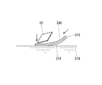
本発明の実施の形態を図面を参照して詳細に述べると、図1は、本発明が適用される水圧転写方法を概略的に示し、この水圧転写方法は、印刷パターン340が施された水溶性フィルム314から成る転写フィルム316(図3(A)参照)の印刷パターン340上に活性剤320を塗布してインクを活性化した後、この転写フィルム316を印刷パターン340が上面となるようにして図示しない転写槽内の水318上に供給して浮かばせ、水圧転写すべき物品10をこの転写フィルム316を介して水318の中に押し込んで(図1及び図3(B)参照)物品10の表面に印刷パターン340に相応するパターンを有する印刷層(又は加飾層)30(図2及び図3(C)参照)を有する加飾物品10Dを形成する方法である。なお、印刷パターン340のインクの成分や、水溶性フィルム314、活性剤その他の構成要素の材料は、後に述べる実施の形態及び実施例に記載されたものに限定されるものではなく、また物品10は、この水圧転写前に下地処理を適宜施すことができる。
An embodiment of the present invention will be described in detail with reference to the drawings. FIG. 1 schematically shows a water pressure transfer method to which the present invention is applied. After applying the
水溶性フィルム314は、水を吸収して湿潤し軟化する例えばポリビニールアルコールを主成分とする水溶性材料から成っている。この水溶性フィルム314は、水圧転写時に、転写槽内の水に触れて軟化し、水圧転写を容易にする。印刷パターン340は、水溶性フィルム314の上にグラビア印刷等によって施され、この転写フィルム316は、印刷パターン340のインクを乾燥した状態で保管し、水圧転写時に活性剤を用いて活性化される。
The water-
その後、印刷層30が形成された加飾物品10Dは、活性剤を硬化する硬化工程(図3(D)参照)、水溶性フィルム314を除去するシャワー洗浄工程(図3(E)参照)、物品の表面を乾燥する乾燥工程(図3(F)参照)を経て、完成品となる。
Thereafter, the
図示していないが、実際には、物品10は、適宜のコンベヤで搬送されたり、ロボットアームに支持されたりしながら水中に押し入れられる。また、場合によっては、印刷パターン340上に活性剤320を塗布する工程と転写フィルム316を水に浮かばせる工程とは、その工程の順序を逆にして、水に浮かばせた転写フィルム316の印刷パターン340上に活性剤320をスプレー塗布してもよい。
Although not shown, the
本発明の方法においては、図4(A)及び図6(A)に示すように、印刷パターン340は、インク層312Iを有する第1の領域312Aと、インク層を有しないか第1の領域312Aよりも薄いインク層を有する第2の領域312Bとから成り、第2の領域312内に活性剤の余剰分を集合するのに必要な空間を有し、且つ印刷パターン340の上に全外表面柄固定層を有しない転写フィルム316が用いられる。第1の領域312Aの活性剤に対する界面張力は、第2の領域312Bの活性剤に対する界面張力よりも低く設定されているのが好ましいが、その理由は、後述する。
In the method of the present invention, as shown in FIGS. 4A and 6A, the
活性剤320が転写フィルム316に塗布されると、この活性剤320は、印刷パターン312の第1の領域312Aのインク層312Iに浸透しながらこのインク層312Iを活性化してインク層の印刷時の状態と同じような付着性を復元して印刷パターン312の水圧転写を可能にするが、それと同時に以下に詳細に述べるように、物品10の表面に転写フィルム316の印刷パターン340を水圧転写して形成される印刷層(加飾層)30(図2参照)のインク印刷部分30Aとインク印刷部分30Aとの間の空間(中間空間)30Bに印刷パターン312を活性化するのに用いられる活性剤320の余剰分320Rを凸状に集合しながら転移させてこの中間空間30Bにインク印刷部分30Aよりも高い凸部30BPを形成して立体的な凹凸触感を付与する。
When the
このように、転写フィルム316の印刷パターン340を活性化するための活性剤余剰分を物品の印刷層30のインク印刷部分30Aの間に凸状に集合して凸部30BPを形成するためには、次の2つの形態があり、第1の形態は、後に図4及び図5を参照して詳細に述べるが、転写フィルム316に塗布された活性剤の余剰分320Rを印刷パターン340のインク印刷部分312Aの間に流し込むようにして転写時にその余剰分320Rをインク印刷部分312Aの間に集合させながら物品の表面に転移させて凸部30BPを形成する形態であり、第2の形態は、後に図6及び図7を参照して詳細に述べるが、活性剤の余剰分320Rを印刷パターン340の第1の領域312Aのインク層312Iによるはじき作用と活性剤320の集合力とによって第2の領域312Bで凸状に集合させた後、転写時に、第2の領域312Bの活性剤凸状集合部分320Cを物品の表面に凹凸反転させて凸部30BPを形成する形態である。この第1の形態の方法と第2の形態の方法とは、単独で又は両者相俟って行われると考えられるが、以下にそれぞれの方法を具体的に述べる。いずれの場合も、活性剤320は、インク印刷部分312に浸透してインクを活性化するのに必要な量を越えて凸部32BPを形成するのに必要な余剰量を塗布する必要がある。
Thus, in order to form the convex portion 30BP by gathering the surplus of the activator for activating the
第1の形態の方法が図4及び図5に示されており、図4(A)に示される転写フィルム316に、図4(B)に示すように、活性剤320が塗布されると、この活性剤320は、印刷パターン312の乾燥している第1の領域312Aのインク層312Iに浸透してこのインク層312Iに付着性を復元するので、この転写フィルム316と共に物品10を上方から水中に押し込むと、印刷パターン312が物品10の表面に印刷層(加飾層)30として水圧転写されるが、この際、第1の領域312Aの上方にある活性剤320の余剰分320RAと第2の領域312B内にある活性剤320の余剰分320RBとがその流動性によって物品10の表面に押されて第2の領域312B内に流れ込みながら集合し(図4(C)参照)、第1の領域312Aのインク印刷部分312Iに相応する隣り合うインク印刷部分(印刷層30のインクを有する部分)30Aの間の空間(第2の領域312Bに相応する部分)30B内に凸状に転移し、この空間30B内に活性剤の集合による凸部30BPを形成する(図4(C)参照)。なお、この凸部30BPは、第2の形態に関連して図6(F)を参照して詳細に述べるように、硬化時に収縮差を生じさせて凸部30BPの周りにインク印刷部分30Aよりも低い凹部を形成して高低差を一層顕著にすることができる。
The method of the first embodiment is shown in FIGS. 4 and 5, and when the
物品10を転写フィルム316を介して水中に押し込む状態が図5に詳細に示されており、この場合、物品10が水に付き回る速さよりも転写フィルム316が物品に付き回る速さの方を速くすると、凸部30BPの高さが一層顕著になるので好ましい。その理由は、後に図7を参照して述べる第2の形態による方法と同じである。なお、図1及び図4では、物品10は、便宜的に扁平であるのが示されているが、図5では、物品10は、転写フィルム316の付き回りの説明を容易にするために、高さと丸みとがある形態で示されている。
The state in which the
活性剤320は、通常の溶剤型活性剤でもよいが、好ましくは、インクに活性作用を付与することができる光重合性モノマー含有の紫外線硬化樹脂組成物、特に、無溶剤型の紫外線硬化樹脂組成物であるのが好ましい。この活性剤320は、例えば、グラビアロール、ミヤバー又はスプレーの何れかの方法で転写フィルム316に塗布することができる。活性剤には、レべリング剤、増感剤、充填材、不活性有機ポリマー、チキソトロピー付与剤、熱重合禁止剤、艶消し成分等を添加することができる。空間30に形成された凸部分30BPは、溶剤を含んでいるときにはこの溶剤を飛ばして硬化する樹脂成分であり、また無溶剤型である場合には、紫外線硬化される樹脂成分である。
The
次に、第2の形態による方法が図6及び図7に示されており、図6(A)に示される転写フィルム316に、図6(B)に示すように、活性剤320が塗布されると、この活性剤320は、印刷パターン312の乾燥している第1の領域312Aのインク層312Iに浸透してこのインク層312Iに付着性を復元するが、図6(C)に示すように、活性剤の余剰分320Rがインク層312Iの低い界面張力によってはじかれながら第2の領域312Bに移行し、またこの第2の領域312B内で活性剤自体の集合力が作用して第2の領域312Bで活性剤が凸状に集合する。図6(C)を参照すると、活性剤320の余剰分がインク層312Iを有する第1の領域312Aからインク層を有しない(又は薄いインク層を有する)第2の領域312Bに集合してやや盛り上がっているのが解る。このインクの盛り上がり部分を以下に活性剤凸状集合部分320Cと称する。この活性剤凸状集合部分320Cの盛り上がり高さは、数μm程度である。
Next, the method according to the second embodiment is shown in FIGS. 6 and 7, and an
インク層312Iの活性剤320に対する界面張力の調整は、活性剤320中のレベリング剤を調整することによって行うことができる。活性剤320中のレべリング剤を増加すると、第1の領域312Aのインク層312Iの活性剤320に対する界面張力が低下し、第2の領域312Bへの活性剤320の集合力を高めることができる。なお、第2の領域312Bに第1の領域312Aのインク層312Iよりも薄いインク層を設ける場合に、この第2の領域312Bのインク層の厚みは、後述する凹凸反転を阻害しない程度に設定する。例えば、グラビア印刷により第2の領域312Bに薄いインク層を設ける場合には、この薄いインク層は、例えば、極めて微細で相互に独立するドット状に設けられ、またインク層が活性剤で完全に溶解され活性剤を着色するものを用いるのが好ましい。この第2の領域312Bに充填される材料(薄いインク層又は活性剤)が着色されていると、着色を施さない場合に視認される物品の表面の肌色を隠蔽し、物品の表面の印刷層又は加飾層30の外観を良好にすることができる。
Adjustment of the interfacial tension of the
活性剤中に配合されるレベリング剤は、印刷パターン340のインクの組成との相性に応じて適宜調整されるが、レべリング剤が少なすぎる(レベリング性が全くない)と、第1の領域312Aのインク層312Iによるはじき作用が強すぎて第2の領域312Bへの活性剤の集合力は高まるものの、活性剤のインク層312Iへの十分な浸透(活性化)を確保することができない傾向が発生する。また、逆に、レべリング剤が多すぎると、インクのはじき作用が低くなって活性剤の集合力が低下して活性剤凸状集合部分320Cの高さが小さくなり凹凸反転によって形成される凸部30BPもレベリングされて低くなってしまう傾向が発生する欠陥がある。従って、レべリング剤は、このような欠陥を生ずることがないような範囲で調整される。好ましいレベリング剤としては、有機変性ポリシロキサンの如きシリコン系レベリング剤やポリアクリレートの如きアクリル系レベリング剤やBYKR―UV3500(登録商標)で市販されているジメチルポリシロキサンを骨格とするUVコーティング用レベリング剤がある。これらのレベリング剤は、0.01乃至3重量%の割合で活性剤に含有するのが好ましい。また、活性剤の集合力が高まると、第2の領域312Bの活性剤凸状集合部分320Cの高さが第1の領域の高さよりも高くなる傾向が発生するが、その高さは、それぞれの領域の特性、すなわちインクの固形分や顔料の如き成分や領域の間隔、活性剤の塗布量等によって異なり、レベリングの調整によって、例えば2〜10μm程度、第2の領域312Bが第1の領域312Aよりも高くなるように活性剤の集合力を高くするとよい。
The leveling agent blended in the activator is appropriately adjusted according to the compatibility with the ink composition of the
第2の形態に用いられる活性剤320も、好ましくは、レベリング剤を所定量配合した光重合性モノマー含有の無溶剤タイプの紫外線硬化樹脂組成物から成っている。この活性剤320も、グラビアロール、ミヤバー又はスプレーの何れかの方法で転写フィルム316に塗布することができ、またこの活性剤には、レべリング剤の他に、必要に応じて、活性剤のはじき作用と集合力を阻害しない程度において、増感剤、充填材、不活性有機ポリマー、チキソトロピー付与剤、熱重合禁止剤、艶消し成分等を添加することができる。
The
活性剤320に対する界面張力を高める(水溶性フィルムの第2の領域となる表面の濡れ性をよくする)ために、予め印刷パターンを施す前の水溶性フィルム314に、例えば、UV照射による表面改質等の如き表面処理を施してもよく、このようにすると、第2の領域312Bの活性剤320の集合力を一層高めることができる。
In order to increase the interfacial tension with respect to the activator 320 (in order to improve the wettability of the surface serving as the second region of the water-soluble film), the surface modification by UV irradiation, for example, is applied to the water-
このようにして、印刷パターン活性剤320を塗布して第2の領域312Bに活性剤凸状集合部分320Cが形成された転写フィルム316を用いて、図6(D)に示すように、物品10に印刷パターン340を水圧転写するが、このとき、図6(E)に示すように、第2の領域312Bの活性剤凸状集合部分320Cが転写フィルム316の水溶性フィルム314側に押し上げられるように、凹凸反転されながら、転写フィルム316の印刷パターン340が物品10の表面に転写される。即ち、転写フィルム316の水溶性フィルム314とは反対側に凸であった活性剤凸状集合部分320Cは、水圧転写によって、物品10の表面によって今まで凸であった部分が物品10の表面に反動的に押されて水溶性フィルム314側に凸となるように反転されて物品の表面上に装飾層(印刷パターン340の付着によって形成された層)30側に凸となる部分30BPを形成する。活性剤凸状集合部分320Cのこの凹凸反転は、印刷パターン340にインク層を有しない部分かインク層の薄い部分があり、且つこの印刷パターン340の全外表面を覆う全外表面柄固定層を有しないことによって達成される。
In this way, as shown in FIG. 6D, the
なお、活性剤凸状集合部分320Cの凹凸反転は、転写フィルム316を縦横の少なくともいずれかに収縮するように物品10の表面に付き回させて行うのが好ましいが、この転写フィルム316の収縮による物品10の表面への付き回しは、物品が水に付き回る速さよりも転写フィルムが物品に付き回る速さが速くなるようにして行うことができる。このようにすると、この部分320C(凸部30BP)の突出を一層顕著にすることができる。
In addition, it is preferable to perform the reversal of the concave and convex portions of the activator convex
この動きを図7を参照して一層具体的に説明すると、図7(A)に示すように、物品10を印刷パターン340に押しつけるときに、図7(B)及び図7(C)に示すように、印刷パターン340をその長手方向に沿って物品10側に寄せるようにして転写すると、第2の領域312Bと第1の領域312Aの間隔が狭められつつ物品10に沿うように転写されるが、実際には、第1の領域312Aは、インク層312Iを有するのに対して第2の領域312Bは、インク層を有しないかあってもインク層が薄いので、第1の領域312Aの幅よりも先に第2の領域312Bの幅の方がより狭められ、従って、狭くなった第2の領域312Bの空間内に活性剤余剰分が一層高く突出するように集合される(図7(B)参照)。このように活性剤余剰分が一層高く突出した状態で上方から物品10と接触するので、物品10の表面に押されて凹凸反転した時に、水溶性フィルム314側へ顕著に凸となるのである(図7(D)参照)。
This movement will be described in more detail with reference to FIG. 7. As shown in FIG. 7A, when the
印刷パターン340を物品10側に寄せるように収縮するために、静水式の転写槽を用いる水圧転写(転写毎に所定大きさの新しい転写フィルムを転写槽内に浮遊させて行う水圧転写)の場合には、その内部の水上で十分に膨潤した水溶性フィルム314を物品10を水没させる位置の両側から物品10の着水点へ寄せるようにしつつ物品10を水没させ、また水318が上流から下流に流れる流水式の転写槽を用いる水圧転写の場合には、物品10と水流との相対速度を物品側が遅くなるように(水流速度が速くなるように)移動させつつ水溶性フィルム314上の印刷パターン340を物品10へ一層寄せるようにして印刷パターン340を狭めたりすることができる。
In the case of hydraulic transfer using a hydrostatic transfer tank in order to shrink the printed
図6(E)、図7(C)(D)の凹凸反転工程後、UV照射硬化装置322を用いて印刷層又は装飾層30(当初の印刷パターン340)をUV硬化させ(図3(D)、図6(F)参照)、その後、図3(E)を参照して説明したように、表面の残留した水溶性フィルム314をシャワー洗浄機324によって除去し、最後に物品の表面を乾燥機(例えばエアブロアー)326によって乾燥して微細な凹凸表面を有する加飾物品10Dを完成する。なお、本発明においては、装飾層30を硬化する工程(図3(D)参照)と水溶性フィルム314を除去する工程(図3(E)参照)とを逆にしてもよい。また、表面の乾燥は、自然乾燥であってもよい。
6E, 7C and 7D, the printed layer or decoration layer 30 (original print pattern 340) is UV cured using the UV irradiation curing device 322 (FIG. 3D). ), FIG. 6 (F)), and then, as described with reference to FIG. 3 (E), the water-
装飾層30の硬化は、使用する活性剤が溶剤型である場合には、加熱硬化であり、使用する活性剤が紫外線硬化型活性剤である場合には、紫外線硬化であり、使用する活性剤に応じて適宜の方法が選択される。
Curing of the
この装飾層30の硬化は、装飾層30の表面から硬化させるのが好ましい。このようにすると、図6(F)に示すように、装飾層30の凸部30BPのトップからサイドにかけて表面が先に硬化して収縮が開始し、この表面硬化に追従するように、内部が次第に収縮し始める。このため、柔軟性を有する内部の変形がおこり、内部を細くさせることで上方に凸形状を先細るように変形させることになり触指感が向上する。特に、この硬化速度を速めると、凸部30BPの収縮が一層大きくなってその高さ(先細り)が増大するので、この速度を調整することによっても凹凸差を適宜設定することができる(図5(D)及び図7(D)参照)。
The
また、インク層312Iを有する第1の領域312Aは、インクの固形分を多くしたり顔料の濃度を高くしたりすることによってその収縮を抑制することができる。このように、インクの収縮を抑制することによって、第1の領域312Aと第2の領域312Bとの間に大きな収縮差を生じさせて凸部分30BPの凸形状を一層先細るように変形させることができる。
The
装飾層30を硬化するUV照射硬化装置322は、低圧又は高圧の水銀ランプ、メタルハライドランプの如き光源ランプと照射器(ランプハウス)を含む任意の形態とすることができる。
The UV
UV照射硬化装置322は、UV照射によって活性剤凸状集合部分320C(凸部30BP)の表面を一気に硬化させるようにするのが好ましい。このように、一気に表面の皮膜を形成すると、第1の領域312Aに相応するインク印刷部分(第1の表面部分)30Aと第2の領域312Bに相応する部分(第2の表面部分)30Bとの収縮変形を顕著にすることができる。即ち、このように活性剤凸状集合部分320Cを一気に表面硬化させて収縮変形を高めると、第1の表面部分30Aと第2の表面部分30Bとの境目で両方から同時に「引け」を起こし、図6(F)に示すような凸部30BPの側面に高低差の低い(装飾層30のインク印刷部分=第1の表面部分30Aより低い)凹部分を形成しつつ、「引け」の部分の樹脂を第2の表面部分30Bの凸部30BPへと変形移行させることになり、凹部の減少した体積分を凸部へ移行させつつ、凸部30BPを一層高くすることができ、一層顕著な凹凸を形成することができる。ちなみに、溶剤含有型又は溶剤非含有型の紫外線硬化樹脂組成物の活性剤を用いると、印刷パターンの紫外線硬化時に活性剤凸状集合部分も紫外線硬化するが、その後表面の水溶性フィルムを洗浄し除去することによって、凸部30BPが水溶性フィルム314で覆われて空気に接触しない状態で紫外線硬化させることができるので、表面の硬化を一層速めて凹凸差を一層顕著にすることができる。
The UV
なお、本発明においては、表面保護層(トップコート層)を設けると、装飾層30の凹凸による立体感を損ねるため、表面保護層を設けない方が好ましいが、装飾層30の凹凸に倣った表面保護層であれば、表面保護層を設けることを必ずしも否定しない。
In the present invention, when a surface protective layer (topcoat layer) is provided, the stereoscopic effect due to the unevenness of the
図8は、以下に述べる実施例によって得られた加飾物品10Dの実物を示し、加飾物品10Dの表面に顕著な微細凹凸が形成されているのが解る。図2の断面図では、装飾層30が第1の表面部分30Aと第2の表面部分30Bとを分けるように示されているが、実際には両表面部分とも堅牢かつ一体的になっている。
FIG. 8 shows the actual
次に、本発明の2つの実施例1、2を比較例1、2と比較しつつ、これらの例によって得られた加飾物品の実物拡大写真(図8、図11は、実施例1、2、図9、図10は、比較例1、2の写真)を参照して説明する。図8乃至図11の写真とその凹凸の高低差とは、「キーエンス社製」カラーレーザー顕微鏡とそのコントローラ:VK−8700、測定部:VK−8710を使用し、測定倍率×1000で測定したものである。 Next, while comparing the two examples 1 and 2 of the present invention with the comparative examples 1 and 2, the actual enlarged photographs of the decorative articles obtained by these examples (FIGS. 8 and 11 show the examples 1, 2, FIG. 9 and FIG. 10 will be described with reference to photographs of Comparative Examples 1 and 2. The photographs shown in FIGS. 8 to 11 and the height difference between the projections and depressions are those measured at a measurement magnification of 1000 using a “Keyence” color laser microscope and its controller: VK-8700, measurement unit: VK-8710. It is.
(実施例1)
この実施例1は、次の要領で実施された。
(1)転写フィルムは、図12に示すように、楕円形のドットが点在する印刷パターン部分(第1の領域)とドット間の印刷パターンのない部分(第2の領域)とから成る印刷パターンを有し、本出願人の一方の出願人である株式会社キュービックが水圧転写技術のライセンス先に「サークルチェックブラック2C」の「柄ナンバーK0200」と称する商品名で販売しているものであって、この商品から全外表面柄固定層又は全面インク層を有していないものを用いた。なお、「サークルチェック」の転写フィルムのパターンについて具体的に説明すると、図12に示すように、A部(縦)873.88μm、B部(横)580.28μmの整列間隔で互い違いに整列した楕円(C部(横)684.56μm、D部(縦)1011.27μm)サークル状にパール顔料系インク層から成る印刷パターンを有し、この楕円サークル状のインク層は約2μmの厚さを有し、また、水溶性フィルムは、約40μmの厚さを有している。なお、実際に販売しているものは、この全表面にさらにシルバー顔料インク等からなる全外表面固定層を設けたものであるが、本発明では、全外表面固定層を設ける前の状態の転写フィルムを用いている。
(2)被転写体である物品には、10cm×20cm×3mmのABS樹脂製の平板が用いられ、この物品に、図3(A)乃至図3(F)に示す工程順で前記転写フィルムを水圧転写した。
(3)活性剤としては、大橋化学工業株式会社製の商品名「ユービックSクリアー33−N2」と称する無溶剤タイプの紫外線硬化樹脂組成物を使用し、この活性剤は、転写フィルムを転写槽内に導入する直前にミヤバー塗布方法によって転写フィルムの印刷パターン上に塗布した。
(4)このようにして活性化された転写フィルムを流水式の転写槽の水面上に順次供給して浮かばせ、活性剤のはじき作用と集合力によって凹凸を形成した後に、図1に示すように、転写フィルムを介して物品を水中に押し込んで水圧転写し、物品を水中から取り出した後、紫外線を照射し、水洗、乾燥を行って水圧転写品(加飾物品10D)を得た。
(5)このような条件において得られた物品の表面には、高低差で約12μmの凹凸を有し柄と一体的に隣接した装飾層(表面柄)が形成された。
Example 1
This Example 1 was implemented as follows.
(1) As shown in FIG. 12, the transfer film has a printing pattern portion (first region) interspersed with elliptical dots and a portion (second region) having no printing pattern between dots. Cubic Co., Ltd., one of the applicants of this application, has a pattern and is sold under the trade name “pattern number K0200” of “Circle Check Black 2C” as a license destination for hydraulic transfer technology. In addition, the product which does not have the entire outer surface pattern fixed layer or the entire surface ink layer was used. Specifically, the pattern of the transfer film of “Circle Check” will be described in detail. As shown in FIG. 12, the patterns are alternately arranged at an alignment interval of A part (vertical) 873.88 μm and B part (horizontal) 580.28 μm. An ellipse (C part (horizontal) 684.56 μm, D part (vertical) 1011.27 μm) has a print pattern composed of a pearl pigment-based ink layer in a circle shape, and this elliptical circle-shaped ink layer has a thickness of about 2 μm. The water-soluble film has a thickness of about 40 μm. In addition, what is actually sold is the one in which the entire outer surface fixing layer made of silver pigment ink or the like is further provided on the entire surface, but in the present invention, the state before the entire outer surface fixing layer is provided. A transfer film is used.
(2) The article is a transfer object, 10 cm × 20 cm × 3 mm in ABS resin flat plate is used, in this article, before Symbol transferred in the order of steps shown in FIG. 3 (A) through FIG. 3 (F) The film was hydraulically transferred.
(3) As an activator, a solvent-free UV curable resin composition called “Uvic S Clear 33-N2” manufactured by Ohashi Chemical Industry Co., Ltd. is used, and this activator uses a transfer film as a transfer tank. Immediately before being introduced into the film, it was coated on the printed pattern of the transfer film by a Miyabar coating method.
(4) After the transfer film activated in this way is sequentially supplied and floated on the water surface of the flowing water type transfer tank, and irregularities are formed by the repelling action and collective force of the activator, as shown in FIG. Then, the article was pushed into the water through the transfer film and hydraulically transferred, and the article was taken out of the water, then irradiated with ultraviolet rays, washed with water and dried to obtain a hydraulically transferred product (decorated
(5) On the surface of the article obtained under such conditions, a decorative layer (surface pattern) having an unevenness of about 12 μm with a height difference and adjacent to the pattern was formed.
図8の実物拡大写真は、実施例1により得られた加飾物品の表面の状態を示す。この写真から解るように、凹凸(高低差12.13μm)付きの装飾層は、触指するまでもなく、明らかに柄にリアルな立体感が付与されている。 The real enlarged photograph of FIG. 8 shows the state of the surface of the decorative article obtained in Example 1. As can be seen from this photograph, the decorative layer with irregularities (altitude difference 12.13 μm) clearly gives a realistic three-dimensional effect to the pattern without touching it.
(比較例1)
比較例1は、転写フィルムとして、印刷パターンの上に、シルバー顔料が添加された透明インクの全外表面柄固定層をグラビア印刷によって形成してこの印刷パターンと全外表面柄固定層との厚みが約4μmである転写フィルム(株式会社キュービック製の商品名「サークルチェックブラック2C」の「柄ナンバーK0200」の転写フィルムを使用したことを除いて、実施例1と同様の工程で印刷パターンを水圧転写した。従って、この比較例1では、活性剤の余剰分は、第1の領域のインク層によるはじき作用と活性剤の集合力との両方が作用することがなく、第2の領域で活性剤が集合しない。図9の実物拡大写真は、この比較例1によって得られた加飾物品の表面状態を示し、この写真から解るように、表面の凹凸の高低差が僅かに3μm程度でしかなく、触指しても、柄の立体感はさらっとした程度で凹凸感や立体感は付与されていない。これは、転写フィルムが全外表面柄固定層を有するため、凹凸反転がされない結果である。
(Comparative Example 1)
In Comparative Example 1, as a transfer film, a transparent ink to which a silver pigment is added is formed on a print pattern as an entire outer surface pattern fixed layer by gravure printing, and the thickness of the print pattern and the entire outer surface pattern fixed layer is formed. A transfer film having a thickness of about 4 μm (except for the use of a transfer film with a “pattern number K0200” of the product name “Circle Check Black 2C” manufactured by Cubic Co., Ltd.). Therefore, in Comparative Example 1, the surplus of the active agent is not activated in the second region without both the repelling action by the ink layer in the first region and the collective force of the activator. 9 shows the surface state of the decorative article obtained in Comparative Example 1, and as can be seen from this photograph, the surface unevenness of the surface is slightly different. It is only about μm, and even if it is touched with a finger, the pattern has a smooth three-dimensional effect, and no unevenness or three-dimensional effect is imparted. The result is not.
(比較例2)
比較例2は、比較例1と同様の転写フィルムを用いたが、活性剤として、大橋化学工業株式会社製の商品名「C.P.A−H NORMAL EX」と称する溶剤タイプの樹脂組成物を用いた点で比較例1と異なる。図10の実物拡大写真は、この比較例2によって得られた加飾物品の表面状態を示し、この写真から解るように、その表面の凹凸の高低差が僅かに1.8μm程度でしかなく、凹凸触感(触覚的な立体感)は全く付与されていない。これも、比較例1と同様に、転写フィルムが全外表面柄固定層を有するため、凹凸反転がされない結果である。
(Comparative Example 2)
In Comparative Example 2, the same transfer film as in Comparative Example 1 was used. However, as an activator, a solvent-type resin composition referred to as trade name “CPAH NORMAL EX” manufactured by Ohashi Chemical Industry Co., Ltd. Is different from Comparative Example 1 in that The actual enlarged photograph of FIG. 10 shows the surface state of the decorative article obtained in Comparative Example 2, and as can be seen from this photograph, the height difference of the unevenness of the surface is only about 1.8 μm, Uneven texture (tactile three-dimensional effect) is not given at all. Similarly to Comparative Example 1, this is also the result that the projections and depressions are not reversed because the transfer film has the entire outer surface pattern fixed layer.
(実施例2)
実施例2は、図7(A)乃至(C)に示すように、物品10に対して転写フィルムの付き回り速度を種々変えながら印刷パターンが凹凸反転するようにして水圧転写したことを除いて実施例1と同様の方法で実施した。実施例2の(A)乃至(C)は、それぞれ物品表面の転写フィルムの付き回り速度を異ならせた3つの例である。
(Example 2)
In Example 2, as shown in FIGS. 7 (A) to (C), except that the printing pattern was reversed and transferred to the
その結果は、図11の実物拡大写真に示すような結果が得られた。
(A)転写フィルムの両側を固定して物品を水没させて転写フィルムの物品への付き回り速度は、水への付き回り速度と同じで水圧転写した場合(水流速度と転写フィルムのコンベヤ速度とを同じ1.3m/分とした場合)であり、その結果、物品に形成された「サークルチェック」の凹凸高低差は、図11(A)の実物拡大写真に示すように、11.37μmであった。
(B)転写フィルムの両側を、図7(B)(C)に示すように、狭めて物品表面の水への付き回り速度より約1.4倍に速度を早めて転写フィルムが付き回るようにした場合(水流速度1.3m/分に対して転写フィルムのコンベヤ速度0.9m/分とした場合)であり、その結果、物品に形成された「サークルチェック」の凹凸高低差は、図11(B)の実物拡大写真に示すように、16.75μmであった(これは、(A)の場合よりも約5.38μm高くなった)。
(C)転写フィルムの両側を、図7(B)(C)とは逆に、広げるように、物品表面の水への付き回り速度より約0.7倍に遅くして転写フィルムが付き回るようにした場合(水流速度1.3m/分に対して転写フィルムのコンベヤ速度1.7m/分とした場合)であり、その結果、物品に形成された「サークルチェック」の凹凸高低差は、図11(C)の実物拡大写真に示すように、9.31μmであった(これは、(A)の場合よりも約2.06μm低くなった)。
これらの例から解るように、転写フィルムの柄の間隔(第2の領域の幅又は大きさ)を狭めるようにして密着させることで物品に形成される凹凸をより顕著にすることができる。なお、本明細書において、「物品の水への付き回り速度」は、上記の説明から理解されるように、印刷パターンと物品表面とが1対1で密着することを基準にしており、印刷パターンと物品表面とが1未満対1のように印刷パターンを延ばす場合には、「物品の水への付き回り速度」が遅く、逆の場合には、「物品の水への付き回り速度」が速いと表現している。
As a result, a result as shown in the actual enlarged photograph of FIG. 11 was obtained.
(A) When both sides of the transfer film are fixed and the article is submerged and the transfer speed of the transfer film to the article is the same as that of water, and hydraulic transfer is performed (the water flow speed and the transfer film conveyor speed) As a result, the uneven height difference of “Circle Check” formed on the article is 11.37 μm as shown in the actual enlarged photograph of FIG. 11 (A). there were.
(B) As shown in FIGS. 7B and 7C, the both sides of the transfer film are narrowed so that the transfer film wraps around at a speed approximately 1.4 times faster than the speed at which the article surface is attached to water. (The case where the transfer film has a conveyor speed of 0.9 m / min with respect to a water flow speed of 1.3 m / min), and as a result, the unevenness height difference of the “circle check” formed on the article is 11 (B), which was 16.75 μm (this was about 5.38 μm higher than that in (A)), as shown in the actual enlarged photograph.
(C) Contrary to FIGS. 7B and 7C, both sides of the transfer film are spread about 0.7 times slower than the speed at which the article surface is attached to water so that the transfer film is attached. In this case (when the water flow speed is 1.3 m / min and the transfer film conveyor speed is 1.7 m / min), the uneven height difference of the “circle check” formed on the article is As shown in the actual enlarged photograph of FIG. 11C, it was 9.31 μm (this was about 2.06 μm lower than in the case of (A)).
As can be seen from these examples, the unevenness formed on the article can be made more conspicuous by closely contacting the pattern of the transfer film (the width or size of the second region). In the present specification, the “approach speed of the article to water” is based on the fact that the printing pattern and the article surface are in close contact with each other as understood from the above description. When the printed pattern is extended so that the pattern and the surface of the article are less than one-to-one, the “approach speed of the article to water” is slow, and in the opposite case, “approach speed of the article to water”. Is expressed as fast.
本発明の水圧転写方法によれば、印刷パターン自体に微細な立体凹凸を付与するので、物品の加飾に一体化した凹凸特性を得て物品の表面に印刷パターンに相応したリアルな立体的な触感を得ることができ、またこの物品の表面の凹凸は、印刷パターンを活性化する活性剤の転写時の圧力によるインク印刷部分間の空間への流れ込みや、インクによるはじき作用と活性剤自体の集合力によって転写フィルム上に形成された活性剤凸状集郷部分を水圧転写時に凹凸反転して形成されるので、別途の工程を必要とすることなく、高い作業性で凹凸触感を得ることができ、高い産業上の利用性を有する。 According to the hydraulic transfer method of the present invention, since a fine three-dimensional unevenness is imparted to the printing pattern itself, the unevenness characteristic integrated with the decoration of the article is obtained, and the realistic three-dimensionality corresponding to the printing pattern is obtained on the surface of the article. Tactile sensation can be obtained, and the unevenness of the surface of the article can flow into the space between the ink printing parts due to the pressure during transfer of the activator that activates the printing pattern, and the ink repelling action and the activator itself Since the active agent convex gathering part formed on the transfer film by the gathering force is formed by reversing the unevenness at the time of hydraulic transfer, it can obtain uneven texture with high workability without requiring a separate process And has high industrial applicability.
10 物品
10D 加飾物品
30 印刷層(装飾層)
30A インク印刷部分
30B インク印刷部分以外の部分(空間)
30BP 凸部(空間30Bに活性剤余剰分が凸状に流れ込み又は反転した部分)
312A 第1の領域
312I インク層
312B 第2の領域
312C 第2領域を凹凸反転して得られる印刷パターン
314 水溶性フィルム
316 転写フィルム
318 水
320 活性剤
320C 活性剤凸状集合部分
340 印刷パターン
10
30A
30BP Convex (part where surplus activator flowed or inverted into
Claims (10)
Priority Applications (12)
| Application Number | Priority Date | Filing Date | Title |
|---|---|---|---|
| JP2007277501A JP5242990B2 (en) | 2007-10-25 | 2007-10-25 | Water pressure transfer method, water pressure transfer film and water pressure transfer product |
| TW097139212A TWI427006B (en) | 2007-10-25 | 2008-10-13 | A water pressure transfer method, a water pressure transfer film and a water pressure transfer article |
| MYPI2010001838A MY165700A (en) | 2007-10-25 | 2008-10-24 | A water pressure transfer method, a transfer film for water pressure transfer and a water pressure transfer article |
| PCT/JP2008/069304 WO2009054482A1 (en) | 2007-10-25 | 2008-10-24 | Method of hydraulic transfer, transfer film for hydraulic transfer, and hydraulic-transfer article |
| EP08841988.2A EP2221189B1 (en) | 2007-10-25 | 2008-10-24 | Method of hydraulic transfer |
| US12/739,409 US8794149B2 (en) | 2007-10-25 | 2008-10-24 | Water pressure transfer method, a transfer film for water pressure transfer and a water pressure transfer article |
| CA2703117A CA2703117C (en) | 2007-10-25 | 2008-10-24 | A water pressure transfer method, a transfer film for water pressure transfer and a water pressure transfer article |
| PL08841988T PL2221189T3 (en) | 2007-10-25 | 2008-10-24 | Method of hydraulic transfer |
| CN2008801225698A CN101909901B (en) | 2007-10-25 | 2008-10-24 | Method of hydraulic transfer, transfer film for hydraulic transfer, and hydraulic-transfer article |
| KR1020107011316A KR101479286B1 (en) | 2007-10-25 | 2008-10-24 | Method of hydraulic transfer, transfer film for hydraulic transfer, and hydraulic-transfer article |
| HK11101722.0A HK1147725A1 (en) | 2007-10-25 | 2011-02-22 | Method of hydraulic transfer, transfer film for hydraulic transfer, and hydraulic-transfer article |
| US14/448,668 US9090118B2 (en) | 2007-10-25 | 2014-07-31 | Water pressure transfer method, a transfer film for water pressure transfer and a water pressure transfer article |
Applications Claiming Priority (1)
| Application Number | Priority Date | Filing Date | Title |
|---|---|---|---|
| JP2007277501A JP5242990B2 (en) | 2007-10-25 | 2007-10-25 | Water pressure transfer method, water pressure transfer film and water pressure transfer product |
Publications (2)
| Publication Number | Publication Date |
|---|---|
| JP2009101657A JP2009101657A (en) | 2009-05-14 |
| JP5242990B2 true JP5242990B2 (en) | 2013-07-24 |
Family
ID=40579584
Family Applications (1)
| Application Number | Title | Priority Date | Filing Date |
|---|---|---|---|
| JP2007277501A Expired - Fee Related JP5242990B2 (en) | 2007-10-25 | 2007-10-25 | Water pressure transfer method, water pressure transfer film and water pressure transfer product |
Country Status (11)
| Country | Link |
|---|---|
| US (2) | US8794149B2 (en) |
| EP (1) | EP2221189B1 (en) |
| JP (1) | JP5242990B2 (en) |
| KR (1) | KR101479286B1 (en) |
| CN (1) | CN101909901B (en) |
| CA (1) | CA2703117C (en) |
| HK (1) | HK1147725A1 (en) |
| MY (1) | MY165700A (en) |
| PL (1) | PL2221189T3 (en) |
| TW (1) | TWI427006B (en) |
| WO (1) | WO2009054482A1 (en) |
Families Citing this family (17)
| Publication number | Priority date | Publication date | Assignee | Title |
|---|---|---|---|---|
| CA2759168A1 (en) | 2009-04-30 | 2010-11-04 | Taica Corporation | A water pressure transfer method, a water pressure transfer article and a coating agent for a water pressure transfer film |
| CN102753356B (en) | 2010-02-22 | 2014-12-10 | 泰卡株式会社 | Matting activator for hydraulic transfer film, hydraulic transfer method, and hydraulic transfer product |
| TW201129480A (en) * | 2010-02-26 | 2011-09-01 | Hirotech Transfer Technology Company Ltd | Method of creating three-dimensional patterns on the object surface |
| TW201242795A (en) * | 2011-01-20 | 2012-11-01 | Taica Corp | A water pressure transfer method, a transfer film for water pressure transfer, an ink for a transfer film and a water pressure transfer article |
| CN102285261A (en) * | 2011-06-09 | 2011-12-21 | 曹人天 | Printing film as well as preparation method and printing process thereof |
| CN104203593B (en) * | 2012-03-22 | 2018-03-27 | 株式会社可乐丽 | Hydraulic-transfer basement membrane |
| CN103862903B (en) * | 2012-12-11 | 2016-06-08 | 黄北江 | A kind of new type water transfer coating film |
| CN103862904B (en) * | 2012-12-11 | 2016-12-21 | 黄北江 | A kind of water transfer surface coating thin film |
| US20140166196A1 (en) * | 2012-12-15 | 2014-06-19 | Michael Flynn | Golf ball alignment device |
| TWI552887B (en) * | 2014-06-12 | 2016-10-11 | Daigin Chemical Co Ltd | Water pressure transfer method and transfer film structure |
| US9989919B2 (en) | 2013-07-30 | 2018-06-05 | Daigin Chemical Co., Ltd. | Method for forming a hydraulic transfer film, hydraulic transfer film, and patterned article |
| JP6410508B2 (en) | 2014-05-20 | 2018-10-24 | トリニティ工業株式会社 | Decorative parts and manufacturing method thereof |
| TWI589459B (en) * | 2014-09-26 | 2017-07-01 | Daigin Chemical Co Ltd | Water pressure transfer method for producing relief touch |
| WO2016123740A1 (en) * | 2015-02-02 | 2016-08-11 | 浙江大学 | Calculable 3d color printing method |
| TWI705906B (en) * | 2019-05-17 | 2020-10-01 | 大勤化成股份有限公司 | Water pressure transfer method for producing relief |
| CN111942071B (en) * | 2019-05-17 | 2021-11-30 | 大勤化成股份有限公司 | Hydraulic transfer method for producing relief |
| CN114589921A (en) * | 2020-12-04 | 2022-06-07 | 中国石油化工股份有限公司 | 3D printing equipment and workpiece printing and coloring method |
Family Cites Families (12)
| Publication number | Priority date | Publication date | Assignee | Title |
|---|---|---|---|---|
| US3811915A (en) * | 1971-04-27 | 1974-05-21 | Inmont Corp | Printing method for forming three dimensional simulated wood grain,and product formed thereby |
| JPH05270199A (en) * | 1992-03-26 | 1993-10-19 | Toppan Printing Co Ltd | Manufacture of decorative sheet |
| JPH0640198A (en) | 1992-07-27 | 1994-02-15 | Kiyuubitsuku:Kk | Method of modifying surface of fluid-pressure transfer article |
| JP3482506B2 (en) | 1994-04-11 | 2003-12-22 | 株式会社キュービック | Decorative construction product having irregular surface and its manufacturing method |
| CN1122090C (en) * | 1997-04-11 | 2003-09-24 | 株式会社丘比克 | Liquid pressure transfer ink, liquid pressure transfer film, liquid pressure transfer product and liquid pressure transfer method |
| KR20030035933A (en) * | 2001-10-30 | 2003-05-09 | 다이니혼 잉키 가가쿠 고교 가부시키가이샤 | Hydraulic transfer method |
| TWI382934B (en) * | 2003-10-22 | 2013-01-21 | Kuraray Co | Hydraulic transfer method,sheet for hydraulic transfer and base film for hydraulic transfer |
| JP3881002B2 (en) * | 2004-02-18 | 2007-02-14 | 株式会社キュービック | Water pressure transfer method and water pressure transfer product |
| WO2007023525A1 (en) * | 2005-08-23 | 2007-03-01 | Taica Corporation | Coating agent for hydraulic transfer film, method of hydraulic transfer and hydraulic transfer product |
| JP2007098608A (en) * | 2005-09-30 | 2007-04-19 | Dainippon Printing Co Ltd | Hydraulic pressure transferring method |
| JP2007090836A (en) * | 2005-09-30 | 2007-04-12 | Dainippon Printing Co Ltd | Sheet for hydraulic transfer |
| CA2759168A1 (en) * | 2009-04-30 | 2010-11-04 | Taica Corporation | A water pressure transfer method, a water pressure transfer article and a coating agent for a water pressure transfer film |
-
2007
- 2007-10-25 JP JP2007277501A patent/JP5242990B2/en not_active Expired - Fee Related
-
2008
- 2008-10-13 TW TW097139212A patent/TWI427006B/en not_active IP Right Cessation
- 2008-10-24 PL PL08841988T patent/PL2221189T3/en unknown
- 2008-10-24 MY MYPI2010001838A patent/MY165700A/en unknown
- 2008-10-24 KR KR1020107011316A patent/KR101479286B1/en not_active IP Right Cessation
- 2008-10-24 WO PCT/JP2008/069304 patent/WO2009054482A1/en active Application Filing
- 2008-10-24 CA CA2703117A patent/CA2703117C/en not_active Expired - Fee Related
- 2008-10-24 EP EP08841988.2A patent/EP2221189B1/en not_active Not-in-force
- 2008-10-24 US US12/739,409 patent/US8794149B2/en not_active Expired - Fee Related
- 2008-10-24 CN CN2008801225698A patent/CN101909901B/en not_active Expired - Fee Related
-
2011
- 2011-02-22 HK HK11101722.0A patent/HK1147725A1/en not_active IP Right Cessation
-
2014
- 2014-07-31 US US14/448,668 patent/US9090118B2/en not_active Expired - Fee Related
Also Published As
| Publication number | Publication date |
|---|---|
| EP2221189A4 (en) | 2012-11-14 |
| US8794149B2 (en) | 2014-08-05 |
| CA2703117A1 (en) | 2009-04-30 |
| EP2221189B1 (en) | 2014-03-19 |
| KR101479286B1 (en) | 2015-01-05 |
| US20100229745A1 (en) | 2010-09-16 |
| MY165700A (en) | 2018-04-20 |
| US20150020703A1 (en) | 2015-01-22 |
| CN101909901A (en) | 2010-12-08 |
| WO2009054482A1 (en) | 2009-04-30 |
| CA2703117C (en) | 2014-08-12 |
| PL2221189T3 (en) | 2014-08-29 |
| CN101909901B (en) | 2013-03-27 |
| US9090118B2 (en) | 2015-07-28 |
| TWI427006B (en) | 2014-02-21 |
| HK1147725A1 (en) | 2011-08-19 |
| JP2009101657A (en) | 2009-05-14 |
| EP2221189A1 (en) | 2010-08-25 |
| KR20100090698A (en) | 2010-08-16 |
| TW200927520A (en) | 2009-07-01 |
Similar Documents
| Publication | Publication Date | Title |
|---|---|---|
| JP5242990B2 (en) | Water pressure transfer method, water pressure transfer film and water pressure transfer product | |
| KR101051289B1 (en) | Hydraulic Transfer Method and Hydraulic Transfer | |
| JP5616332B2 (en) | Water pressure transfer method, water pressure transfer product and coating agent for water pressure transfer film | |
| TWI312734B (en) | Water pressure transfer method and water pressure transfer article | |
| JP4166816B2 (en) | Water pressure transfer method, water pressure transfer product and coating agent for water pressure transfer film | |
| FR2827529A1 (en) | Article with coating imitating droplets for cosmetics packaging, uses liquid which is printed onto surface of article and then dries to form a pattern resembling liquid droplets | |
| JP3806737B2 (en) | Water pressure transfer method and water pressure transfer product | |
| KR20120095931A (en) | Activating agent for hydraulic transfer film, hydraylic transfer method, and hydraulic transfer product | |
| JP2021154727A (en) | Hydraulic pressure transfer method | |
| CN101405152A (en) | Films for decorating glass and methods of their production | |
| JP3826362B2 (en) | Hydrostatic transfer method for surface protective layer and hydraulic transfer product | |
| TWI331099B (en) | Water pressure transfering method and water pressure transfer article | |
| JP2686542B2 (en) | Method for manufacturing molded article with tuned embossed pattern | |
| JPH07237286A (en) | Decorative sheet and its production |
Legal Events
| Date | Code | Title | Description |
|---|---|---|---|
| A621 | Written request for application examination |
Free format text: JAPANESE INTERMEDIATE CODE: A621 Effective date: 20100128 |
|
| A131 | Notification of reasons for refusal |
Free format text: JAPANESE INTERMEDIATE CODE: A131 Effective date: 20120911 |
|
| A521 | Request for written amendment filed |
Free format text: JAPANESE INTERMEDIATE CODE: A523 Effective date: 20121108 |
|
| TRDD | Decision of grant or rejection written | ||
| A01 | Written decision to grant a patent or to grant a registration (utility model) |
Free format text: JAPANESE INTERMEDIATE CODE: A01 Effective date: 20130402 |
|
| A61 | First payment of annual fees (during grant procedure) |
Free format text: JAPANESE INTERMEDIATE CODE: A61 Effective date: 20130404 |
|
| FPAY | Renewal fee payment (event date is renewal date of database) |
Free format text: PAYMENT UNTIL: 20160412 Year of fee payment: 3 |
|
| R150 | Certificate of patent or registration of utility model |
Ref document number: 5242990 Country of ref document: JP Free format text: JAPANESE INTERMEDIATE CODE: R150 Free format text: JAPANESE INTERMEDIATE CODE: R150 |
|
| R250 | Receipt of annual fees |
Free format text: JAPANESE INTERMEDIATE CODE: R250 |
|
| R250 | Receipt of annual fees |
Free format text: JAPANESE INTERMEDIATE CODE: R250 |
|
| R250 | Receipt of annual fees |
Free format text: JAPANESE INTERMEDIATE CODE: R250 |
|
| R250 | Receipt of annual fees |
Free format text: JAPANESE INTERMEDIATE CODE: R250 |
|
| R250 | Receipt of annual fees |
Free format text: JAPANESE INTERMEDIATE CODE: R250 |
|
| R250 | Receipt of annual fees |
Free format text: JAPANESE INTERMEDIATE CODE: R250 |
|
| R250 | Receipt of annual fees |
Free format text: JAPANESE INTERMEDIATE CODE: R250 |
|
| LAPS | Cancellation because of no payment of annual fees |