JP5232177B2 - Opposing fluid control systems for active and passive actuation of actuators - Google Patents
Opposing fluid control systems for active and passive actuation of actuators Download PDFInfo
- Publication number
- JP5232177B2 JP5232177B2 JP2009551856A JP2009551856A JP5232177B2 JP 5232177 B2 JP5232177 B2 JP 5232177B2 JP 2009551856 A JP2009551856 A JP 2009551856A JP 2009551856 A JP2009551856 A JP 2009551856A JP 5232177 B2 JP5232177 B2 JP 5232177B2
- Authority
- JP
- Japan
- Prior art keywords
- pressure
- load
- return
- spool
- fluid
- Prior art date
- Legal status (The legal status is an assumption and is not a legal conclusion. Google has not performed a legal analysis and makes no representation as to the accuracy of the status listed.)
- Expired - Fee Related
Links
Images


Classifications
-
- F—MECHANICAL ENGINEERING; LIGHTING; HEATING; WEAPONS; BLASTING
- F15—FLUID-PRESSURE ACTUATORS; HYDRAULICS OR PNEUMATICS IN GENERAL
- F15B—SYSTEMS ACTING BY MEANS OF FLUIDS IN GENERAL; FLUID-PRESSURE ACTUATORS, e.g. SERVOMOTORS; DETAILS OF FLUID-PRESSURE SYSTEMS, NOT OTHERWISE PROVIDED FOR
- F15B13/00—Details of servomotor systems ; Valves for servomotor systems
- F15B13/02—Fluid distribution or supply devices characterised by their adaptation to the control of servomotors
- F15B13/04—Fluid distribution or supply devices characterised by their adaptation to the control of servomotors for use with a single servomotor
- F15B13/0401—Valve members; Fluid interconnections therefor
- F15B13/0402—Valve members; Fluid interconnections therefor for linearly sliding valves, e.g. spool valves
-
- F—MECHANICAL ENGINEERING; LIGHTING; HEATING; WEAPONS; BLASTING
- F15—FLUID-PRESSURE ACTUATORS; HYDRAULICS OR PNEUMATICS IN GENERAL
- F15B—SYSTEMS ACTING BY MEANS OF FLUIDS IN GENERAL; FLUID-PRESSURE ACTUATORS, e.g. SERVOMOTORS; DETAILS OF FLUID-PRESSURE SYSTEMS, NOT OTHERWISE PROVIDED FOR
- F15B11/00—Servomotor systems without provision for follow-up action; Circuits therefor
- F15B11/006—Hydraulic "Wheatstone bridge" circuits, i.e. with four nodes, P-A-T-B, and on-off or proportional valves in each link
-
- F—MECHANICAL ENGINEERING; LIGHTING; HEATING; WEAPONS; BLASTING
- F15—FLUID-PRESSURE ACTUATORS; HYDRAULICS OR PNEUMATICS IN GENERAL
- F15B—SYSTEMS ACTING BY MEANS OF FLUIDS IN GENERAL; FLUID-PRESSURE ACTUATORS, e.g. SERVOMOTORS; DETAILS OF FLUID-PRESSURE SYSTEMS, NOT OTHERWISE PROVIDED FOR
- F15B2211/00—Circuits for servomotor systems
- F15B2211/30—Directional control
- F15B2211/305—Directional control characterised by the type of valves
- F15B2211/3056—Assemblies of multiple valves
- F15B2211/30565—Assemblies of multiple valves having multiple valves for a single output member, e.g. for creating higher valve function by use of multiple valves like two 2/2-valves replacing a 5/3-valve
- F15B2211/30575—Assemblies of multiple valves having multiple valves for a single output member, e.g. for creating higher valve function by use of multiple valves like two 2/2-valves replacing a 5/3-valve in a Wheatstone Bridge arrangement (also half bridges)
-
- F—MECHANICAL ENGINEERING; LIGHTING; HEATING; WEAPONS; BLASTING
- F15—FLUID-PRESSURE ACTUATORS; HYDRAULICS OR PNEUMATICS IN GENERAL
- F15B—SYSTEMS ACTING BY MEANS OF FLUIDS IN GENERAL; FLUID-PRESSURE ACTUATORS, e.g. SERVOMOTORS; DETAILS OF FLUID-PRESSURE SYSTEMS, NOT OTHERWISE PROVIDED FOR
- F15B2211/00—Circuits for servomotor systems
- F15B2211/30—Directional control
- F15B2211/32—Directional control characterised by the type of actuation
- F15B2211/329—Directional control characterised by the type of actuation actuated by fluid pressure
-
- F—MECHANICAL ENGINEERING; LIGHTING; HEATING; WEAPONS; BLASTING
- F15—FLUID-PRESSURE ACTUATORS; HYDRAULICS OR PNEUMATICS IN GENERAL
- F15B—SYSTEMS ACTING BY MEANS OF FLUIDS IN GENERAL; FLUID-PRESSURE ACTUATORS, e.g. SERVOMOTORS; DETAILS OF FLUID-PRESSURE SYSTEMS, NOT OTHERWISE PROVIDED FOR
- F15B2211/00—Circuits for servomotor systems
- F15B2211/30—Directional control
- F15B2211/35—Directional control combined with flow control
- F15B2211/351—Flow control by regulating means in feed line, i.e. meter-in control
-
- F—MECHANICAL ENGINEERING; LIGHTING; HEATING; WEAPONS; BLASTING
- F15—FLUID-PRESSURE ACTUATORS; HYDRAULICS OR PNEUMATICS IN GENERAL
- F15B—SYSTEMS ACTING BY MEANS OF FLUIDS IN GENERAL; FLUID-PRESSURE ACTUATORS, e.g. SERVOMOTORS; DETAILS OF FLUID-PRESSURE SYSTEMS, NOT OTHERWISE PROVIDED FOR
- F15B2211/00—Circuits for servomotor systems
- F15B2211/70—Output members, e.g. hydraulic motors or cylinders or control therefor
- F15B2211/705—Output members, e.g. hydraulic motors or cylinders or control therefor characterised by the type of output members or actuators
- F15B2211/7051—Linear output members
- F15B2211/7053—Double-acting output members
Description
関連出願
本願は、全体が参照によって本明細書に援用される、2007年2月28日に米国特許商標庁に出願された米国仮特許出願第60/904,245号の利益を主張する。
Related Applications This application claims the benefit of US Provisional Patent Application No. 60 / 904,245 filed with the US Patent and Trademark Office on February 28, 2007, which is incorporated herein by reference in its entirety.
本発明は、一般に、サーボおよびサーボタイプのシステム、ならびにこれらのシステム内に含まれる弁に関する。より詳細には、本発明は、対立する流体制御システムに関し、複数の対立する作動装置がそれぞれの圧力制御弁によって制御される。 The present invention relates generally to servos and servo type systems, and valves included in these systems. More particularly, the present invention relates to opposing fluid control systems, where multiple opposing actuators are controlled by respective pressure control valves.
油圧または空気圧のシステムなどの制御システムまたはサーボシステムはよく知られており、作用位置から出力位置まで流体によって力を伝達するという単純な原理で作動する。油圧システムにおいては、この伝達は、典型的に、中に包含されたピストンを有する作動装置シリンダによって達成され、このピストンが、実質的に圧縮不可能な流体を、流体管路を介して、異なる位置にある、やはりピストン有する別のシリンダへと押す。油圧システムによって力を伝達することの1つの大きな利点は、2つのシリンダを連結する流体管路が任意の長さおよび形状であってよく、2つのピストンを分離する様々な位置において屈曲したり、または曲がったりしてよいことである。流体管路は、また、複数の他の流体管路に分かれてもよく、これによって、1つの主ピストンが複数の従ピストンを駆動できるようになる。油圧システムの別の利点は、出力位置において作用される力を増減するのが非常に容易であることである。この油圧力の増加は、一方のピストンの他方のピストンに対するサイズを変えることによって達成される。 Control systems or servo systems such as hydraulic or pneumatic systems are well known and operate on the simple principle of transmitting force by fluid from the working position to the output position. In hydraulic systems, this transmission is typically accomplished by an actuator cylinder having a piston contained therein, which differs from a substantially incompressible fluid via a fluid line. Push to another cylinder in position, still with piston. One major advantage of transmitting force by the hydraulic system is that the fluid line connecting the two cylinders can be of any length and shape, bends at various positions separating the two pistons, Or it can be bent. The fluid line may also be divided into a plurality of other fluid lines, which allows one main piston to drive a plurality of slave pistons. Another advantage of the hydraulic system is that it is very easy to increase or decrease the force applied at the output position. This increase in oil pressure is achieved by changing the size of one piston relative to the other.
多くの油圧システムでは、シリンダおよびピストンは、実質的に圧縮不可能な流体として機能する高圧の油圧液を供給するポンプに、弁を介して連結される。スプール弁は、油圧システムにおいて最も一般的に使用される弁であり、油圧作動装置内のピストンの前面または背面のいずれにも圧力を掛けることができる。作動装置シリンダの一方の側が加圧された場合、スプール弁は、同時に、作動装置の反対側への戻し管路を開き、ピストンの対向側の実質的に圧縮不可能な油圧液が、戻し貯蔵部内へと戻ることができるようにする。こうして、作動装置の動きに対抗する内部圧力を逃がし、作動装置によって必要とされる仕事を、外部負荷を駆動するのに必要な仕事のみに限定する。結果として、スプール弁は、油圧の力を達成するために流速の効率的な制御が可能であるので、油圧システムに理想的に適している。 In many hydraulic systems, the cylinder and piston are connected via a valve to a pump that supplies high pressure hydraulic fluid that functions as a substantially incompressible fluid. The spool valve is the most commonly used valve in hydraulic systems and can apply pressure to either the front or back of the piston in the hydraulic actuator. When one side of the actuator cylinder is pressurized, the spool valve simultaneously opens the return line to the opposite side of the actuator and the substantially uncompressed hydraulic fluid on the opposite side of the piston is stored back. Be able to return to the department. In this way, the internal pressure against the movement of the actuator is relieved and the work required by the actuator is limited to that required to drive the external load. As a result, spool valves are ideally suited for hydraulic systems because they allow efficient control of flow rates to achieve hydraulic forces.
油圧システムにおけるスプール弁の利点にもかかわらず、既存のスプール弁は、なお、ある構成上の制限を有する。従来のスプール弁は、機械式レバー、電気サーボ機構、またはパイロット弁によって与えられるパイロット圧力と称される内部制御圧力のいずれかによって作動されるように構成されている。スプール弁は、一般に、円筒形のスリーブまたは弁筐体内に取り付けられ、流体ポートがこの筐体を介して延在し、スリーブ内の適切な位置にスプールのランドおよび凹部を配置することによって、互いに流体連通するように開くまたは閉じることができる。作動圧力は、弁を開くかまたは閉じるように弁スプールを移動させ、異なる量の加圧流体が供給貯蔵部から流れることのできるようにすることによって変えられる。 Despite the advantages of spool valves in hydraulic systems, existing spool valves still have certain configuration limitations. Conventional spool valves are configured to be actuated by either a mechanical lever, an electric servomechanism, or an internal control pressure called pilot pressure provided by a pilot valve. Spool valves are generally mounted within a cylindrical sleeve or valve housing, with fluid ports extending through the housing, and by placing the spool lands and recesses in appropriate locations within the sleeve. It can be opened or closed for fluid communication. The operating pressure is varied by moving the valve spool to open or close the valve, allowing different amounts of pressurized fluid to flow from the supply reservoir.
電気的な作動の場合、弁は電気供給源からの入力電流によって制御される。電流は、供給電力がより大きいと、圧力ポートまたは供給ポートがより広く開き、加圧流体が、制限のより少ない状態で弁の中へおよび弁を介して流れることができる点において、システム内の圧力に関係し得る。作動装置の負荷圧力が最終的に供給圧力に等しくなったとき、流れは止まる。言い換えると、所与の電流が、圧力ポートまたは戻しポートの開口部のサイズを制御し、それが、油圧作動装置に向かう、または油圧作動装置から離れる流体の流速を制御する。システムが正しく作動するためには、スプール弁全体に一定の圧力差がなければならない。そうでないと、負荷圧力が供給貯蔵部の圧力に近づくにつれて、弁は線形応答を失い、その作動が不安定になる。結果として、スプール弁は、典型的に、対向する負荷圧力の範囲と比べて供給源(すなわち供給貯蔵部)の圧力が非常に高く、所与の圧力における流れ対入力電流が、使用可能領域において線形であるシステムにおいて作動される。 In the case of electrical actuation, the valve is controlled by an input current from an electrical source. The current in the system is such that the larger the supply power, the wider the pressure port or supply port opens, and the pressurized fluid can flow into and through the valve with less restrictions. Can be related to pressure. When the actuator load pressure eventually equals the supply pressure, the flow stops. In other words, a given current controls the size of the pressure port or return port opening, which controls the flow rate of fluid toward or away from the hydraulic actuator. In order for the system to operate correctly, there must be a certain pressure differential across the spool valve. Otherwise, as the load pressure approaches the supply reservoir pressure, the valve loses its linear response and its operation becomes unstable. As a result, spool valves typically have a very high source (i.e., supply reservoir) pressure compared to the range of opposing load pressures, so that flow versus input current at a given pressure is in the usable area. Operated in a system that is linear.
これは、システムおよび特に負荷が常に加圧状態にあり、外部の力によってまたはそれ自体の重量の下では自由に動かすことはできないことを意味する。このように、負荷は、実際の能動的な作動なくして、容易に動かすことはできない。言い換えると、作動装置は受動的には逆向き駆動できない。重力の存在下でさえ、または運動量に応じて(たとえば制動の際)、加圧流体の形の能動的な入力が、負荷を変位または作動させるために必要であるため、このような構成は、非常に能率が悪い。加圧流体の使用は、負荷を動かす、かつ/または制動するために、加圧された新しい流体が常に供給されなければならないため、かなりのエネルギー損失を生じる。 This means that the system and in particular the load is always under pressure and cannot be moved freely by external forces or under its own weight. Thus, the load cannot be easily moved without actual active operation. In other words, the actuator cannot be driven backwards passively. Such an arrangement is because even in the presence of gravity or depending on the momentum (e.g. during braking), an active input in the form of a pressurized fluid is required to displace or actuate the load. Very inefficient. The use of pressurized fluid results in significant energy loss because a new pressurized fluid must always be supplied to move and / or brake the load.
従来のスプール弁の現在の流れの問題に加えて、従来の油圧システムは、他のいくつかの理由のために問題がある。まず、弁およびピストンのサイクルタイムを制御するために、複雑な制御装置が必要である。第2に、出力ピストンを動かすのに大量の流体が必要とされるため、ピストンを動かすサイクルタイムがしばしば長くなる。第3に、出力ピストンを駆動するために必要な大量の流体は、流体蓄圧器の大型の貯蔵部の一定した加圧を必要とする。結果として、油圧機械は、典型的に、作動に大量の油圧流体を必要とし、したがって、任意のシリンダの2つの側によって移動される流体の容量の差を保持するのに、大型の外部貯蔵部が必要となる。 In addition to the current flow problems of conventional spool valves, conventional hydraulic systems are problematic for several other reasons. First, complex control devices are required to control the valve and piston cycle times. Second, the cycle time to move the piston is often lengthy because a large amount of fluid is required to move the output piston. Third, the large amount of fluid required to drive the output piston requires constant pressurization of the large reservoir of the fluid accumulator. As a result, hydraulic machines typically require a large amount of hydraulic fluid to operate, and thus a large external reservoir to hold the difference in volume of fluid moved by the two sides of any cylinder Is required.
従来のスプール弁装置は、また、制御された流れが弁を介して誘導されるとき、通常、作動装置のピストンの制御された速度へと直接移るので、用途に制限がある。結果として、速度入力からシステムへと負荷位置に基づいて油圧エネルギーを変換するために、複雑なシステムフィードバック装置が使用されなければならない。システムにフィードバック制御装置を導入することは、フィードバックループの帯域幅に対するシステムの反応および弁の応答性を制限し、そのため、抵抗する力が掛けられたとき、フィードバック装置と弁との間の時間遅延がシステムを不安定にする。 Conventional spool valve devices are also limited in application because when a controlled flow is induced through the valve, it usually shifts directly to the controlled speed of the actuator piston. As a result, complex system feedback devices must be used to convert hydraulic energy based on load position from the speed input to the system. Introducing a feedback controller in the system limits the response of the system to the feedback loop bandwidth and the responsiveness of the valve, so the time delay between the feedback device and the valve when a resisting force is applied. Makes the system unstable.
従来のサーボシステムにおいて作動する従来のサーボ弁には、さらに他の問題が存在する。上述の問題のために、これらの弁およびシステムは、高帯域では不安定になることなく作動できない。さらに、複数弁システムのすべての弁が使用されてはいないとき、相当な量のエネルギーが、漏れのために失われ得る。最後に、複数のランドおよび凹部が単一のスプールに形成され、単一のスプールが、弁本体に形成された圧力ポートおよび戻しポートを開閉するように機能するので、スプールの構成には限界があり得る。 There are still other problems with conventional servo valves that operate in conventional servo systems. Because of the problems described above, these valves and systems cannot operate without instability at high frequencies. Furthermore, when not all of the valves of the multiple valve system are in use, a significant amount of energy can be lost due to leakage. Finally, because the lands and recesses are formed in a single spool, and the single spool functions to open and close the pressure and return ports formed in the valve body, there is a limit to the configuration of the spool. possible.
従来技術に固有の問題および欠点を考慮して、本発明は、対立する流体制御システムを提供することによって、この問題および欠点を克服しようと努め、このシステムは、単一の作動装置を用いて操作可能な対立する圧力制御弁(以下、「PCV」と称す)、または、それぞれの対立する作動装置を用いて操作可能な複数の圧力制御弁を備えることができる。この圧力制御弁は、機能的および効率的な利点をもたらすように構成される。 In view of the problems and disadvantages inherent in the prior art, the present invention seeks to overcome this problem and drawbacks by providing an opposing fluid control system, which uses a single actuator. There may be an opposing pressure control valve operable (hereinafter referred to as “PCV”) or a plurality of pressure control valves operable using respective opposing actuators. This pressure control valve is configured to provide functional and efficient advantages.
本明細書に具体化され、概略的に説明されるように、本発明は、対立する圧力制御部を用いる流体制御システムに帰し、この流体制御システムは、(a)負荷に連結された作動装置ピストンを有する負荷作動装置であって、負荷の能動的および受動的な変位を容易にするように構成された負荷作動装置と、(b)負荷作動装置を用いて操作可能であり、負荷作動装置のピストンの第1の側に制御圧力を与え、作動装置ピストンおよび負荷の能動的および受動的な変位を容易にするように構成された第1の圧力制御弁と、(c)負荷作動装置を用いて操作可能であり、負荷作動装置のピストンの第2の側に制御圧力を与え、第1の圧力制御弁によって容易にされた方向とは反対の方向への作動装置ピストンおよび負荷の能動的および受動的な変位を容易にするように構成された第2の圧力制御弁であって、第1の圧力制御弁に対立する第2の圧力制御弁とを備え、第1および第2の圧力制御弁は、作動装置ピストンおよび負荷をそれぞれの方向に選択的に駆動する能動弁状態と、作動装置ピストンおよび負荷が、負荷に作用する非作動的な力に応答して受動的に変位できるように、局所的流体が流体制御システム内で前後に分流される受動弁状態とを有する。 As embodied and generally described herein, the present invention is attributed to a fluid control system that employs opposing pressure controls, the fluid control system comprising: (a) an actuator coupled to a load. A load actuator having a piston, the load actuator configured to facilitate active and passive displacement of the load; and (b) operable with the load actuator; A first pressure control valve configured to apply a control pressure to a first side of the piston of the actuator to facilitate active and passive displacement of the actuator piston and load; and (c) a load actuator. Active in the actuator piston and load in a direction opposite to that facilitated by the first pressure control valve, providing a control pressure to the second side of the piston of the load actuator. And passive weird A second pressure control valve configured to facilitate the operation of the second pressure control valve opposite to the first pressure control valve, wherein the first and second pressure control valves are actuated. An active valve state that selectively drives the device piston and load in each direction, and the local fluid so that the actuator piston and load can be passively displaced in response to non-actuating forces acting on the load. Has a passive valve state that is shunted back and forth within the fluid control system.
本発明は、また、対立する圧力制御部を用いる流体制御システムを特徴とし、この流体制御システムは、(a)負荷に連結された作動装置ピストンを有する第1の負荷作動装置であって、負荷の能動的および受動的な変位を容易にするように構成された第1の負荷作動装置と、(b)負荷にやはり連結された作動装置ピストンを有する第2の負荷作動装置であって、負荷の反対方向への能動的および受動的な変位を容易にするように構成された第2の負荷作動装置と、(c)第1の負荷作動装置の作動装置ピストンおよび負荷の能動的および受動的な変位を遂行する制御圧力を与えるように、第1の負荷作動装置を用いて操作可能である第1の圧力制御弁と、(d)第1の圧力制御弁に対立し、制御圧力を与えて第2の負荷作動装置の作動装置ピストンおよび負荷の能動的および受動的な変位を遂行するように、第2の負荷作動装置を用いて操作可能である第2の圧力制御弁とを備え、第1および第2の圧力制御弁は、第1および第2の負荷作動装置の作動装置ピストンを、それぞれ反対方向に選択的に駆動する能動弁状態と、第1および第2の負荷作動装置の作動装置ピストンが、負荷に作用する非作動的な力に応答して受動的に変位できるように、局所的流体が流体制御システム内で前後に分流される受動弁状態とを有する。 The present invention also features a fluid control system that employs opposing pressure controls, the fluid control system comprising: (a) a first load actuator having an actuator piston coupled to a load comprising: A first load actuator configured to facilitate active and passive displacement of the load, and (b) a second load actuator having an actuator piston also coupled to the load, A second load actuator configured to facilitate active and passive displacements in opposite directions, and (c) an active piston and a load active and passive of the first load actuator A first pressure control valve that is operable using the first load actuator to provide a control pressure that performs a desired displacement; and (d) providing a control pressure against the first pressure control valve. Actuator for second load actuator A second pressure control valve operable with a second load actuator to effect active and passive displacement of the piston and load, wherein the first and second pressure control valves are Active valve states that selectively drive the actuator pistons of the first and second load actuators in opposite directions, respectively, and the actuator pistons of the first and second load actuators act on the load. A passive valve state in which the local fluid is diverted back and forth within the fluid control system so that it can be passively displaced in response to an actuating force.
本発明は、負荷を駆動するように構成された流体制御システムを操作する方法をさらに特徴とし、本方法は、(a)独立した圧力スプールおよび戻しスプールを備えて構成される第1の圧力制御弁を設けるステップと、(b)独立した圧力スプールおよび戻しスプールをやはり備えて構成される第2の圧力制御弁を設けるステップであって、前記第2の圧力制御弁が、また、第1の圧力制御弁に対して動作可能に対立するように構成されるステップと、(c)第1の負荷作動装置を第1の圧力制御弁に連結するステップであって、第1の負荷作動装置が負荷を作動させるように構成されるステップと、(d)負荷を作動させるように第1および第2の圧力制御弁を操作するステップとを含む。 The present invention further features a method of operating a fluid control system configured to drive a load, the method comprising: (a) a first pressure control comprising an independent pressure spool and a return spool. Providing a valve; and (b) providing a second pressure control valve that also comprises an independent pressure spool and return spool, wherein the second pressure control valve is also configured to A step configured to be operatively opposed to the pressure control valve; and (c) connecting the first load actuator to the first pressure control valve, wherein the first load actuator is A step configured to actuate the load; and (d) operating the first and second pressure control valves to actuate the load.
上述の方法は、戻し入口ポートおよび戻し出口ポートを開くように第1および第2の圧力制御弁の戻しスプールを変位させるために、パイロット圧力を負荷圧力よりも低くなるように下げるステップと、第1および第2の圧力制御弁と少なくとも1つの負荷作動装置の少なくとも1つとの間で第1および第2の圧力制御弁の戻し入口ポートおよび戻し出口ポートを介して流体を前後に分流させるステップとをさらに含み、それによって、負荷がぶら下がるのを可能にするように負荷に作用する非作動的な力に応答して、第1および第2の負荷作動装置の作動装置ピストンを受動的に変位させる受動弁状態を開始する。さらに、本方法は、第2の負荷作動装置を第2の圧力制御弁に連結するステップをさらに含み、この負荷作動装置は、第1の負荷作動装置によって作動される方向とは反対の方向に負荷を作動させるように構成される。 The method includes lowering the pilot pressure below the load pressure to displace the return spools of the first and second pressure control valves to open the return inlet port and the return outlet port; Diverting fluid back and forth between the first and second pressure control valves and at least one of the at least one load actuator via the return inlet and return outlet ports of the first and second pressure control valves; Further passively displaces the actuator pistons of the first and second load actuators in response to a non-actuating force acting on the loads to allow the load to hang. Initiate a passive valve condition. Further, the method further includes the step of coupling a second load actuator to the second pressure control valve, the load actuator being in a direction opposite to the direction actuated by the first load actuator. Configured to actuate the load.
本発明は、添付の図面と併せて、以下の説明および添付の特許請求の範囲から、より完全により明らかになるであろう。これらの図面は、本発明の例示的な実施形態を示すのみであり、したがって、本発明の範囲を限定するように解釈されるべきではないことを理解されたい。本明細書に概略的に説明され、図に示される、本発明の構成要素は、様々な異なる構成に配置および構成が可能であることは、容易に理解されるであろう。しかしながら、本発明は、以下の添付の図面を参照して、追加の具体性および詳細を用いて記述および説明される。 The present invention will become more fully apparent from the following description and appended claims, taken in conjunction with the accompanying drawings. It should be understood that these drawings depict only exemplary embodiments of the invention and are therefore not to be construed as limiting the scope of the invention. It will be readily appreciated that the components of the present invention as schematically described herein and illustrated in the figures can be arranged and configured in a variety of different configurations. However, the present invention will be described and explained with additional specificity and detail with reference to the accompanying drawings in which:
本発明の例示的な実施形態の以下の詳細な説明は、本発明の一部を形成し、本発明が実施可能である例示的な実施形態を実例によって示す、添付の図面を参照する。これらの例示的な実施形態は、当業者が本発明を実施できるように、十分に詳細に説明されるが、他の実施形態が実現可能であり、本発明の精神および範囲から逸脱することなく、本発明に対する様々な変更が行われ得ることを理解されたい。したがって、本発明の実施形態の以下のより詳細な説明は、請求される本発明の範囲を限定するようには意図されず、例示の目的のために示され、本発明の特色および特徴を説明すること、本発明の最良の実施方法を規定すること、ならびに、当業者が本発明を十分に実施できるようにすることを限定する目的のために示されるのではない。したがって、本発明の範囲は、添付の請求項のみによって規定される。 The following detailed description of exemplary embodiments of the invention refers to the accompanying drawings, which form a part hereof and illustrate, by way of illustration, exemplary embodiments in which the invention can be practiced. These exemplary embodiments are described in sufficient detail to enable those skilled in the art to practice the invention, but other embodiments are possible and do not depart from the spirit and scope of the invention. It should be understood that various modifications to the present invention can be made. Accordingly, the following more detailed description of embodiments of the invention is not intended to limit the scope of the claimed invention, but is presented for purposes of illustration and describes features and characteristics of the invention. It is not intended for the purpose of defining the best practice of the invention, or limiting the ability of those skilled in the art to fully practice the invention. Accordingly, the scope of the invention is defined only by the appended claims.
本発明の以下の詳細な説明および例示的な実施形態は、本発明の要素および特徴が、全体にわたって参照符号によって示される添付の図面を参照して最もよく理解されるであろう。 The following detailed description and exemplary embodiments of the present invention will be best understood by reference to the accompanying drawings, wherein the elements and features of the invention are designated by reference numerals throughout.
本発明は、作動装置に連結された対向する腱などの負荷の制御をもたらすように、少なくとも2つの圧力制御弁(PCV)を互いに対立関係に動作可能に関連させることによる流体制御システムを提供する方法およびシステムを説明する。対立するPCVは、従来の関連した弁に対して大きな機能的および効率的な利点を提供するように構成される。 The present invention provides a fluid control system by operatively associating at least two pressure control valves (PCVs) with each other to provide control of a load, such as opposing tendons, coupled to an actuator. A method and system are described. Opposing PCVs are configured to provide significant functional and efficient advantages over conventional related valves.
まず、本明細書に用いられる「双方向制御」または「双方向圧力調整」という用語は、単一の圧力制御弁が双方向の圧力調整を遂行する能力を意味するものと理解されたく、圧力制御弁が、作動装置内の作動装置ピストンの両側に作用する圧力を調整および制御して、ピストンを変位し、したがって負荷を双方向に駆動できることを意味する。 First, the terms “bidirectional control” or “bidirectional pressure regulation” as used herein are understood to mean the ability of a single pressure control valve to perform bi-directional pressure regulation. It means that the control valve can regulate and control the pressure acting on both sides of the actuator piston in the actuator to displace the piston and thus drive the load in both directions.
本明細書に用いられる「圧力差」という用語は、システム内のパイロット圧力と負荷圧力との間に不均衡の状態が存在することを意味する、または指すと理解されたい。いくつかの実施形態では、「圧力差」は、負荷圧力とパイロット圧力との間の圧力の大きさにおける単純な差を意味し得る。他の実施形態、すなわち、負荷/力の移動または増加のために領域の縮小を用いる実施形態では、「圧力差」は、弁本体の異なる領域、作動装置、および何らかの油圧の増加を考慮して、負荷圧力とパイロット圧力との間に存在する圧力の、比例関係にない相違を意味し得る。 As used herein, the term “pressure differential” should be understood to mean or refer to the presence of an imbalance between pilot pressure and load pressure in the system. In some embodiments, “pressure difference” may mean a simple difference in the magnitude of pressure between the load pressure and the pilot pressure. In other embodiments, i.e., embodiments that use area reduction for load / force movement or increase, the "pressure differential" takes into account different areas of the valve body, actuators, and some increase in hydraulic pressure. Can mean a non-proportional difference in the pressure existing between the load pressure and the pilot pressure.
本明細書に用いられる「負荷圧力」という用語は、負荷によって誘導されたまたは掛けられた負荷作動装置内に作用する圧力から作動装置機構自体の内部での摩擦または他の損失を引いたものを意味するものと理解されたい。負荷圧力は、フィードバック圧力に直接的に影響および指令を与える。 As used herein, the term “load pressure” refers to the pressure induced in or applied to a load actuator minus the friction or other loss within the actuator mechanism itself. It should be understood as meaning. The load pressure directly affects and commands the feedback pressure.
本明細書に用いられる「フィードバック圧力」という用語は、もしあれば、領域の縮小/増大および流体圧力の増加/分割がすべて発生した後に、負荷圧力によって受けられた、または指令された、圧力制御弁内の独立した戻しスプールおよび圧力スプールのフィードバック圧力側に作用する圧力を意味するように理解されたい。フィードバック圧力は、いくつかの場合では、負荷圧力に等しくなり得る。 As used herein, the term “feedback pressure” refers to the pressure control, if any, received or commanded by the load pressure after all the reduction / increase of the region and the increase / split of fluid pressure have occurred. It should be understood to mean the pressure acting on the feedback pressure side of the independent return spool and pressure spool in the valve. The feedback pressure may be equal to the load pressure in some cases.
本明細書に用いられる「作動装置」または「負荷作動装置」という用語は、流体エネルギーを、機械エネルギーなどの使用可能なエネルギーに変換することのできる任意のシステムまたは装置を意味するものと理解されたい。負荷作動装置の典型的な例は、負荷に連結された油圧作動装置であり、この油圧作動装置は、油圧流体源から加圧された油圧流体を受け、これを、負荷を駆動するのに十分な機械的仕事または力に変換する。 As used herein, the term “actuator” or “load actuator” is understood to mean any system or device capable of converting fluid energy into usable energy, such as mechanical energy. I want. A typical example of a load actuator is a hydraulic actuator coupled to a load that receives pressurized hydraulic fluid from a source of hydraulic fluid, which is sufficient to drive a load. To mechanical work or force
本明細書に用いられる「ぶら下がる」という用語は、負荷に作用する非作動的な力(たとえば外部の力(衝撃)、運動量などから発生される運動エネルギーを利用する力)に応答した、両方向への負荷の非作動的な自由な振れを意味するものと理解されたく、負荷の動きは、負荷を両方向に動かすために流体制御システムから能動的な入力を与えることなく達成され、この状態は、従来の関連した流体制御システムの能動受動性と比較して、非能動受動性と称され得る。ぶら下がるまたは自由に振れる能力は、「揺動モード」で作動する様々な圧力制御弁によって可能になる。 As used herein, the term “hanging” is used in both directions in response to a non-actuating force acting on a load (eg, a force that utilizes kinetic energy generated from an external force (impact), momentum, etc.). It is to be understood that this means a non-operating free run-out of the load, and the movement of the load is achieved without providing an active input from the fluid control system to move the load in both directions, Compared to the active passivity of conventional related fluid control systems, it can be referred to as inactive passivity. The ability to hang or swing freely is made possible by various pressure control valves operating in “rocking mode”.
本明細書に用いられる「揺動」または「揺動モード」という用語は、対立する圧力制御弁の非能動の受動的な弁状態を意味するように理解されたく、それぞれの弁のパイロット圧力または制御圧力が、負荷圧力およびフィードバック圧力ならびに戻し貯蔵部の圧力より低く保たれ、それによって、それぞれの弁の中の戻しスプールを、戻し入口および戻し出口を開く開位置へと変位させて、この位置に保持し、また、加圧流体を止める閉位置に圧力スプールを保持する。パイロット圧力が、負荷圧力およびフィードバック圧力の両方、ならびに戻し貯蔵部の圧力よりも低く、圧力スプールおよび戻しスプールがこの位置にあるとき、局所的な流体が、負荷、およびしたがって作動装置の動きに応答して、圧力制御弁の開いた戻しポートを介して、負荷作動装置と弁との間で前後に分流または揺動することができる。局所的な流体の分流は、抵抗がわずかしかないまたは全くない状態で行われるので、システムのインピーダンスを改善する。さらに、上述のように、局所的な流体のみが前後に分流できるので、システムは、作動を可能にするために加圧流体を能動的に必要とするのではなく、作動装置、圧力制御弁、およびそれらを連結する様々な流体管路に存在する流体のみを使用することになる。圧力供給部内の流体は使用も希釈もされないので、システムの効率を大幅に改善する。 As used herein, the term “swing” or “swing mode” is to be understood to mean an inactive passive valve state of the opposing pressure control valve, the pilot pressure of each valve or The control pressure is kept below the load and feedback pressures and the pressure in the return reservoir, thereby displacing the return spool in each valve to the open position that opens the return inlet and return outlet. And the pressure spool is held in a closed position to stop the pressurized fluid. When the pilot pressure is lower than both the load pressure and the feedback pressure, and the pressure in the return reservoir, and the pressure and return spools are in this position, the local fluid is responsive to the load and thus the actuator movement. Thus, it is possible to divert or swing back and forth between the load actuating device and the valve via the open return port of the pressure control valve. Local fluid shunting is performed with little or no resistance, thus improving the impedance of the system. Furthermore, as noted above, since only local fluid can be shunted back and forth, the system does not actively require pressurized fluid to enable operation, but the actuator, pressure control valve, And only the fluids present in the various fluid lines connecting them. Since the fluid in the pressure supply is not used or diluted, it greatly improves the efficiency of the system.
揺動モードでは、加圧流体からの能動的な入力(たとえば力)は、従来の関連するサーボシステムおよび流体制御システムの場合のように、作動装置および負荷のいずれの方向への力学にも影響を与える必要はない。実際、従来の関連するシステムは、いくぶん受動的であるのみであり、ある程度の能動的な力または加圧流体が、負荷を一方もしくは両方の方向に作動させるか、または、一方または両方の方向へ負荷が動くようにする必要が依然としてあった。この従来技術の状態は、システムは受動的に見えるけれども、ほんのわずかであっても、実際は能動的であるので、「能動受動性」と称され得る。 In rocking mode, the active input (eg force) from the pressurized fluid affects the dynamics in either direction of the actuator and load, as is the case with conventional associated servo and fluid control systems. There is no need to give In fact, conventional related systems are only somewhat passive, with some active force or pressurized fluid actuating the load in one or both directions, or in one or both directions. There was still a need to allow the load to move. This state of the art can be referred to as “active passivity” because the system appears passive, but even a small amount is actually active.
他方で、圧力制御弁は非能動受動性であることができる。「非能動受動性」とは、サーボまたはサーボタイプのシステム内に包含された圧力制御弁が、パイロット圧力またはパイロット圧力を制御するサーボモータの操作以外、システムからのいかなる能動的な入力または影響なくして、課せられた外部または内部の条件に応じて負荷が動くまたは「ぶら下がる」ようにする能力のことを指す。より具体的には、非能動受動性は、作動装置または負荷を動かすまたは作動させるために、供給貯蔵部からの加圧流体を全く必要としない。
複式独立スプール圧力制御弁
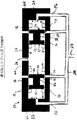
図1を参照すると、図示されているのは、弁システム、すなわち、複式独立スプール圧力制御弁の例示的な一実施形態の長さ方向の断面に沿った断面図である。具体的には、図1は、油圧システムなどの閉回路流体制御システム内の圧力を調整するように構成される、複式独立スプール圧力制御弁(PCV)10を示す。図示の例示的な実施形態では、PCV10は、戻し入口ポート14と、戻し出口ポート16と、圧力入口ポート18と、圧力出口ポート20と、戻しスプールフィードバックポート22および圧力スプールフィードバックポート24の形態の第1および第2のフィードバックポートと、パイロット圧力ポート26とが中に形成された直列線形構造からなる弁本体12を備える。PCV10は、ともに、弁本体12の内側に配設され、その長さ方向の軸を中心に位置された複式の独立したスプール、すなわち戻しスプール40および圧力スプール50をさらに備える。戻しスプール40および圧力スプール50は、弁本体12内に自由に配設および支持されており、スプール停止部34、44、54および58といった1つまたは複数の制限手段によって動きが制限されている。
On the other hand, the pressure control valve can be inactive passive. “Inactive passivity” means that a pressure control valve contained within a servo or servo type system eliminates any active input or influence from the system other than the operation of the pilot motor or the servo motor that controls the pilot pressure. Refers to the ability of a load to move or “hang” depending on imposed external or internal conditions. More specifically, inactive passivity does not require any pressurized fluid from the supply reservoir to move or activate the actuator or load.
Dual Independent Spool Pressure Control Valve Referring to FIG. 1, illustrated is a cross-sectional view along a longitudinal section of an exemplary embodiment of a valve system, ie, a dual independent spool pressure control valve. . Specifically, FIG. 1 shows a dual independent spool pressure control valve (PCV) 10 that is configured to regulate pressure in a closed circuit fluid control system, such as a hydraulic system. In the illustrated exemplary embodiment, the
図示のように、弁本体12のこの特定の実施形態は、弁本体12の壁部分によって中に画定された内部空洞部60を有する、円筒形の管の形状の構造体を備える。内部空洞部60は、戻しスプール40および圧力スプール50のそれぞれを包含または収容し、また、これらスプールの変位を許容するように構成される。実際、内部空洞部60は、戻しスプール40および圧力スプール50の直径または断面積よりわずかに大きい直径または断面積を有し、それによって、戻しスプール40および圧力スプール50が中で双方向に動くことができ、また、必要に応じて弁本体12の壁部分の内表面に対して十分に封止することができる。戻しスプール40および圧力スプール50に対する内部空洞部60のサイズは、戻しスプール40および圧力スプール50が、中で前後に変位される際に、内部空洞部60内でその向きを維持することができるようなものである。
As shown, this particular embodiment of the
内部空洞部60ならびに戻しスプール40および圧力スプール50また、封止された関係を達成するように構成可能である。本質的に、弁本体12、および特に内部空洞部60は、中に様々なチャンバを画定している。図1に示すように、弁本体12は、戻しスプール40と圧力スプール50との間の距離または領域によって画定されたパイロット圧力チャンバ28と、戻しスプール40と弁本体12の端部との間の領域によって画定された戻しスプールフィードバックチャンバ62と、圧力スプール50と弁本体12の対向する端部と間の領域によって画定された圧力スプールフィードバックチャンバ68とを備える。これらのチャンバのそれぞれは、PCVの作動時の戻しスプール40および圧力スプール50の一方または両方の実際の変位によって、サイズが変化する。チャンバ62および68のそれぞれは、戻しスプール40および圧力スプール50と弁本体12の壁の内表面との相互作用によって、パイロット圧力チャンバ28から封止されている。
Inner cavity 60 and return
弁本体12と戻しスプール40および圧力スプール50との間に封止された関係をもたらすことで、望ましくない流体の混和および圧力の漏れを排除することによって、システムの保全性を維持するように機能する。戻しスプール40および圧力スプール50は、当技術において既知の任意の手段を使用して弁本体12に対して封止された関係を有してよい。図1の実施形態では、内部の漏れが非常に低い、許容できる封止が、非常に厳しい製作公差を用いることにより達成されている。この方式の結果、スプール40および50と弁本体12の内壁との間の摩擦が非常に低くなる。しかしながら、いずれのタイプの封止構成が使用されても、戻しスプール40および圧力スプール50は、パイロット圧力とフィードバック圧力とを等しくするために、システム内で作用する圧力差に応答して変位するように構成される。
Provides a sealed relationship between the
戻しスプール40および圧力スプール50は両方とも、弁本体12の内部空洞部60の幾何学的な構成または形状に合致もしくは実質的に合致、または一致する幾何学的な構成または形状を備える。図示のように、戻しスプール40および圧力スプール50は、概ね円筒形の形状であり、2つのランドおよび各ランドの間の凹部を備え、また、第1および第2の側を備える。具体的には、図1に示される実施形態では、戻しスプール40は、パイロット圧力側42、フィードバック圧力側46、第1ランド72、第2ランド74、およびランド72とランド74との間に延在する凹部82を備える。圧力スプール50は、やはり、パイロット圧力側52、フィードバック圧力側56、第1ランド76、第2ランド78、およびランド76とランド78との間に延在する凹部84を備える点において、同様の幾何学的な構成または設計を有する。
Both the
上述のように、戻しスプール40のフィードバック側46は、戻しスプールフィードバックチャンバ62と流体連通しており、一方、パイロット圧力側42は、パイロット圧力チャンバ28と流体連通している。ランド72および74は、弁本体12の内壁面に対して封止することができる適切な直径または断面積を備える。封止されたとき、および戻しスプール40の変位の際、ランド72および74は、フィードバックチャンバ62、凹部82、およびパイロット圧力チャンバ28の間の流体連通または流体の混和を最小にする。さらに、凹部はランド72および74よりも直径が小さいので、戻し入口ポート14から出口ポート16へと流体が正しく流れるのを容易にするように、ランド72および74は、凹部82とともに機能する。これらのポートが開かれると、流体は、戻し入口ポート14を介してPCV10へ入り、戻しスプール40の凹部82を介し、戻し出口ポート16から出る。
As described above, the
また、上述のように、圧力スプール50のフィードバック側56は、圧力スプールフィードバックチャンバ68と流体連通しており、一方、圧力スプール50のパイロット圧力側52は、パイロット圧力チャンバ28と流体連通している。ランド76および78も、やはり、弁本体12の内壁面に対して封止することができる適切な直径または断面積を備える。封止されたとき、および戻しスプール40の変位の際、ランド76および78は、フィードバックチャンバ62、凹部84、およびパイロット圧力チャンバ28の間の流体連通または流体の混和を最小にする。さらに、凹部はランド76および78よりも直径が小さいので、圧力入口ポート18から圧力出口ポート20へと流体が正しく流れるのを容易にするように、ランド76および78は、凹部84とともに機能する。これらのポートが開かれると、流体は、圧力入口ポート18を介してPCV10へ入り、圧力スプール50の凹部84を介し、圧力出口ポート20から出る。
Also, as described above, the
PCV10、および特に弁本体12は、PCV10を介する流体の流れを容易にするように機能し、内部空洞部60と連通する複数のポートをさらに含む。図示の実施形態では、弁本体12は、戻しスプール40および圧力スプール50を位置決めすることによって調節される複数の入口ポートおよび出口ポートを中に形成している。具体的には、弁本体12は、戻し入口ポート14および戻し出口ポート16を備え、フィードバック圧力がパイロット圧力を越える条件において、ポートを介して流体が流れることができ、PCV10、およびPCV10が中で作動しているシステムから圧力を除去できるように、これらのポートを開くように戻しスプール40が変位させられる。弁本体12は、また、加圧された流体の供給源(図示せず)と流体連通した圧力入口ポート18と、圧力出口ポート20とを備え、パイロット圧力がフィードバック圧力を越える条件において、ポートを介して流体が流れることができ、PCV10およびPCV10が中で作動しているシステムの中へ圧力を入力できるように、これらのポートを開くように圧力スプール50が変位させられる。
The
弁本体12に沿った、戻しスプール40および圧力スプール50に対する、戻し入口ポート14および戻し出口ポート16ならびに圧力入口ポート18および圧力出口ポート20の相対位置は、戻し入口ポート14および戻し出口ポート16が開いている、もしくは部分的に開いているとき、圧力入口ポート18および圧力出口ポート20が閉じている、もしくは部分的に閉じている、またはその逆であるように構成される。したがって、PCV10、より詳細には、戻しスプール40および圧力スプール50、戻し入口ポート14および戻し出口ポート16、圧力入口ポート18および圧力出口ポート20は、これらの条件を満たすように構成され、こうして、PCVは、システム内で作用する圧力によって、目的通りに機能できるようになる。本明細書に述べられ、図示されるもの以外の、これらの条件を満たす他の代替構成を、当業者は認識するであろう。
The relative positions of
図1に示される実施形態では、戻し入口ポート14および戻し出口ポート16は、弁本体12内に配置された戻しスプール40によって閉じられた状態で示されている。圧力入口ポート18および圧力出口ポート20は、弁本体12内に配置された圧力スプール50によって閉じられた状態で示されている。この状況または作動構成では、フィードバック圧力およびパイロット圧力が等しく、システムは、釣り合っており、均衡状態にある。言い換えると、戻しスプール40および圧力スプール50のいずれをも変位する圧力差がシステム内に存在しないため、PCV10は静止している。実際、システムが、等しいパイロット圧力とフィードバック圧力との間で釣り合っているため、圧力は、圧力ポート18および20を介してシステム内へ入力されておらず、また、戻しポート14および16を介してシステムから除去されてもいない。したがって、PCVによって制御される作動装置を用いて作動可能ないずれの負荷も、また、静止している。
In the embodiment shown in FIG. 1, the
戻し入口ポート14は、戻しスプール40の凹部82、および油圧作動装置(図示せず)などの負荷作動装置と流体連通する。負荷作動装置内で作用しているのは、負荷によって引き起こされた、または掛けられた負荷圧力から、作動装置機構それ自体の内部の摩擦または他の損失を引いた圧力である。負荷圧力は、フィードバック圧力に、直接的に、影響および指令し、いくつかの場合では、フィードバック圧力に等しくなる。対照的に、戻し出口16は、戻しスプール40の凹部82および主戻し貯蔵部(やはり図示せず)と流体連通する。以下にさらに詳しく述べられるように、これらの様々な各戻しポート間の流体連通は、戻しスプール40によって制御される。フィードバック圧力がパイロット圧力を越えたとき、戻しスプール40は、戻し入口ポート14および戻し出口ポート16を開くように変位させられ、それによって、流体は、戻し入口ポート14を介して、戻しスプール40の凹部82の中へ流れ、その後、戻し出口16を介して、主戻し貯蔵部に向かって流れ、システムから圧力を除去することが理解されるであろう。均衡状態に達すると、戻しスプール40は、戻しポート14および16を閉じるように変位する。
The
複式独立スプール圧力制御弁の特異な一態様は、システム内のパイロット圧力が下げられ、戻しスプール40ならびに戻し入口ポート14および戻し出口ポート16を開き、また、圧力入口ポートおよび圧力出口ポートを覆って戻しスプール50を閉じるのに十分なレベルに維持できることである。このモードでは、PCV10は非能動の受動作動状態になり、負荷の動きに作用し影響を及ぼす外的な力に応答するなどして、戻し入口ポート14および戻し出口ポート16を介して、負荷作動装置(油圧作動装置)と戻し貯蔵部との間で流体を揺動する、または前後に分流することができるように機能する。これによって、効果的に、負荷をいずれの方向にも駆動する能動的な入力を必要とすることなく、負荷が自由に振れるまたはぶら下がることができるようになる。揺動モードにあるPCV10でのぶら下がりの概念は、以下にさらに詳しく述べられる。
A unique aspect of the dual independent spool pressure control valve is that the pilot pressure in the system is reduced, the
圧力入口ポート18は、圧力スプール50の凹部84および加圧流体の供給源(図示せず)と流体連通する。対照的に、圧力出口20は、圧力スプール50の凹部84および負荷作動装置と流体連通する。以下にさらに詳しく述べられるように、これらの様々なポートの間の流体連通は、圧力スプール50によって制御される。しかしながら、パイロット圧力がフィードバック圧力を越えたとき、圧力スプール50は、圧力入口ポート18および圧力出口ポート20を開くように変位し、それによって、加圧された流体が、圧力入口ポート18を介して、圧力スプール50の凹部84へと流れ、その後、圧力出口ポート20を介して流れることができ、負荷作動装置に圧力を供給して、増加した圧力を、能動的に負荷を駆動する力に変換することが理解されるであろう。
The
弁本体12は、対応するパイロット圧力または制御圧力を有する加圧流体を受け、パイロット圧力チャンバ28へと導くように構成されたパイロット圧力ポート26をさらに中に形成している。パイロット圧力ポート26は、ポンプなどの流体源からパイロット圧力チャンバ28へと加圧流体を供給するように構成されるパイロット弁(図示せず)と流体連通する。パイロット圧力ポート26を介してパイロット圧力チャンバ28へと入力された(パイロット圧力で)加圧された流体は、戻しスプール40のパイロット圧力側42および圧力スプール50のパイロット圧力側52に作用するように機能し、戻しスプール40および圧力スプール50が互いに離れるように変位するように影響を与える。さらに、パイロット圧力チャンバ28へのパイロット圧力の入力は、流体フィードバックシステムを介して戻しスプール40および圧力スプール50にやはり作用するフィードバック圧力に対抗する、またはこのフィードバック圧力を打ち消すように機能する。このように、パイロット圧力は、PCV10およびこのシステムのための制御圧力として機能する。実際、パイロット圧力は、戻しスプール40および圧力スプール50の変位、したがってシステム内の圧力を制御するように、フィードバック圧力に対して選択的に上昇もしくは低下させる、または一定に保持することが可能である。パイロット圧力の変更または変化は、非常に迅速に行うことができ、それによって、PCVは、動的に予め決められた固定された圧力の調整器のような働きができるようになる。
The
パイロット圧力チャンバ28のサイズは、フィードバックシステムを介して作用するフィードバック圧力によって対抗される、パイロット圧力の大きさ、ならびに結果として生じる、弁本体内の戻しスプール40および圧力スプール50の変位位置によって変化可能であることが理解されるであろう。したがって、パイロット圧力チャンバ28のサイズ変化は、パイロット圧力とフィードバック圧力との間の関係の関数である。フィードバック圧力の大きさにかかわらず、戻しスプール40および圧力スプール50は互いに接触することを妨げられているため、パイロット圧力チャンバ28は、PCV10内に常に存在することが、やはり理解されるであろう。実際、弁本体12の端部に押し付けられる制限部、ならびに弁本体の内部空洞部60内に戦略的に配置される様々な手段または制限手段のために、戻しスプール40および圧力スプール50は、変位できる距離が制限される。
The size of the
制限手段は、戻しスプール40および圧力スプール50のそれぞれが、弁本体12内で移動できる変位距離を制御するように意図される。より具体的には、制限手段は、PCV10の様々な作動状態または作動モードの間、各スプールの所定の作動位置を確立するように機能する。制限手段の例示的な一形態は、弁本体12内でのスプールの望まれない変位を防ぐように、弁本体12の内部空洞部60内に戦略的に配置された複数のスプール停止部である。図1は、これをスプール停止部34、44、54および58として示す。戻しスプール40および圧力スプール50は、スプール停止部34および54のために互いに接触できず、スプール停止部34は、戻しスプール40がパイロットポート26を決して閉じることができないように戻しスプール40の動きを制限し、スプール停止部54は、圧力スプール50の動きを同様に制限する。したがって、パイロット圧力チャンバ28は、パイロット圧力ポート26を介してパイロット圧力源から流体を受けるように、常に存在し、アクセス可能になっている。
The limiting means is intended to control the displacement distance that each of the
弁本体12の第1端部に形成された戻しスプールフィードバックポート22は、油圧作動装置などの負荷作動装置を含み得る負荷作動装置(図示せず)の流体連通を容易にし、戻しスプールフィードバックチャンバ62および戻しスプール40のフィードバック圧力側46が、フィードバックチャンバ62の1つの境界として機能する。したがって、負荷作動装置からの流体は、戻しスプールフィードバックポート22を介して、フィードバックチャンバ62へと流れることができ、それによって、戻しスプール40のフィードバック圧力側46にフィードバック圧力を伝達している。フィードバックチャンバ62は、このフィードバック圧力を戻しスプール40に及ぼされるフィードバック力に変換する、所定の直径または断面積を有する。
A return
戻しスプールフィードバックチャンバ62のフィードバック圧力が、パイロット圧力チャンバ28のパイロット圧力より高いとき、戻しスプール40は、スプール停止部34に接触するまで、パイロット圧力チャンバ28の中央に向かって変位し、それによって、作動装置の圧力を放出および低下させるように、戻し入口ポート14および戻し出口ポート16を開くことが理解されるであろう。フィードバック圧力およびパイロット圧力が等しくなるまで、戻しスプール40はこの位置に留まる。逆に、フィードバックチャンバ62のフィードバック圧力がパイロット圧力チャンバ28のパイロット圧力より低いとき、戻しスプール40は、スプール停止部44と接触するまで、パイロット圧力チャンバ28から離れるように弁本体12の端部に向かって変位する。この位置では、戻し入口ポート14および戻し出口ポート16は閉じられて、システム圧力が上昇可能になる。戻しスプール40は、フィードバックチャンバ62の圧力が、パイロット圧力チャンバ28のパイロット圧力を再び越えるまで、この位置を保持する。
When the feedback pressure in the return
同様に、弁本体12の第2端部に形成された、圧力スプールフィードバックポート24は、負荷作動装置(図示せず)の圧力スプールフィードバックチャンバ68との流体連通を容易にし、圧力スプール50のフィードバック圧力側56は、フィードバックチャンバ68の1つの境界として機能する。したがって、負荷作動装置からの流体は、圧力スプールフィードバックポート24を介して、フィードバックチャンバ68へと流れることができ、それによって、フィードバック圧力を、圧力スプール50のフィードバック圧力側56に伝達する。フィードバックチャンバ68は、この圧力を圧力スプール50に働くフィードバック力に変換する、所定の直径または断面積を有する。
Similarly, a pressure
圧力スプールフィードバックチャンバ68のフィードバック圧力が、パイロット圧力チャンバ28のパイロット圧力より高いとき、圧力スプール50は、スプール停止部54と接触するまで、パイロット圧力チャンバ28の中央に向かって変位し、それによって、圧力入口ポート18および圧力出口ポート20を閉じることが理解されるであろう。フィードバック圧力およびパイロット圧力が等しくなるまで、圧力スプール50はこの位置を保持する。逆に、フィードバックチャンバ68のフィードバック圧力が、パイロット圧力チャンバ28のパイロット圧力より低いとき、圧力スプール50は、パイロット圧力チャンバ28から離れるように弁本体12の端部に向かって変位し、それによって、圧力入口ポート18および圧力出口ポート20を開けて、システム圧力を上昇させる。圧力スプール50は、フィードバックチャンバ68の圧力が、パイロット圧力チャンバ28のパイロット圧力を再び超えるまで、この位置を保持し、パイロット圧力を再び超えると、圧力入口ポート18および圧力出口ポート20は閉じられる。
When the feedback pressure of the pressure
上述のように、制限手段、すなわち、スプール停止部34、44、54および58は、それぞれ、弁本体12の内部空洞部60内において戻しスプール40および圧力スプール50の動きを制限するように構成される。より具体的には、制限手段は、戻しスプール40および圧力スプール50が、戻し入口ポート14および戻し出口ポート16、圧力入口ポート18および圧力出口ポート20、ならびにパイロット圧力ポート26に対して、確実に、正しく変位および位置合わせするように構成される。上述のように、スプール停止部34および54は、戻しスプール40および圧力スプール50の互いに向かう動きを制限する。具体的には、スプール停止部34は、戻しスプール40がパイロット圧力ポート26を閉じることができないように配置される。スプール停止部34はまた、戻し入口ポート14および戻し出口ポート16と、戻しスプールフィードバックポート22との間の流体連通を防ぐ。
As described above, the limiting means, i.e., spool stops 34, 44, 54 and 58, are configured to limit the movement of the
スプール停止部44は、図示のように、弁本体12の端部に向かって戻しスプール40が変位するのを制限する。具体的には、スプール停止部44は、戻しスプール40がスプール停止部44に接触したとき、戻し入口ポート14および戻し出口ポート16が閉じられるように配置される。スプール停止部44の位置はまた、戻し入口ポート14および戻し出口ポート16と、パイロット圧力チャンバ28との間の流体連通を防ぐことが理解されるであろう。
As shown in the figure, the spool stop 44 limits the displacement of the
スプール停止部54は、戻しスプール40およびパイロットチャンバ28に向かう圧力スプール50の動きを制限する。具体的には、スプール停止部54は、圧力スプール50がスプール停止部54に接触したとき、圧力入口ポート18および圧力出口ポート20が閉じられるように配置される。スプール停止部54は、圧力入口ポート18および圧力出口ポート20が圧力スプールフィードバックポート24と流体連通するのを防ぐ。
The spool stop 54 limits the movement of the
図示のように、スプール停止部58は、弁本体12の端部に向かって圧力スプール50が変位するのを制限する。具体的には、スプール停止部58は、圧力スプール50がスプール停止部58に接触したとき、圧力入口ポート18および圧力出口ポート20が閉じられるように配置される。スプール停止部58の位置はまた、圧力入口ポート18および圧力出口ポート20と、パイロット圧力チャンバ28との間の流体連通を防ぐことが理解されるであろう。
As illustrated, the spool stop 58 limits the displacement of the
上述のように、PCV10は、好ましくは、弁本体12の内部空洞部60内に自由に位置される、または支持される、複式の独立したスプール、すなわち戻しスプール40および圧力スプール50を備える。自由に支持されるというのは、スプールが物理的に互いに、または機械式作動手段もしくは支持手段といった他の任意の構造体もしくは装置に連結していないことを意味する。言い換えると、スプールは弁本体の内部の中で浮いており、それ自体に作用する圧力および弁本体12に配置された任意の制限手段によってのみ、その動きまたは変位を制限されている。一態様では、戻しスプール40および圧力スプール50は、低質量スプールである。しかしながら、スプールの質量は、用途によって異なってよい。
As described above, the
戻しスプール40および圧力スプール50は、弁本体12内で互いに独立して作動するように意図される。本明細書に使用される「独立して」という用語、または「独立して制御および作動される」という語句は、2つのスプールが、個々にまたは別々に作動または制御されること、および、互いに相互連結または相互依存のないことを意味することが意図される。これはまた、戻しスプール40および圧力スプール50は、任意の所与の時間にシステム内に作用している内在する圧力パラメータに応答して変位するか、あるいは変位させられるのであって、任意の機械的または電気的に制御された作動装置または作動システムによって変位する、あるいは変位させられるのではないことを意味する。より具体的には、PCVは、PCVに内在する圧力フィードバックシステムに従って中に含まれるシステム内の圧力を調整するように意図され、戻しスプールおよび圧力スプールは、圧力差を分散し、パイロット圧力とフィードバック圧力とを等しくするために、システム内に発生している、または作用している圧力差に従って変位させられる。図1の実施形態では、戻しスプールおよび圧力スプールの外面に作用するフィードバック圧力が、戻しスプールおよび圧力スプールの内面に同時に作用するパイロット圧力と異なるとき、圧力差が存在する。戻しスプールおよび圧力スプールの対向側に同時に作用するこれらの2つの圧力が異なるとき、および優勢な圧力に依存して、戻しスプールおよび圧力スプールは、適切なポートを開くもしくは閉じるように変位し、全体的なシステム圧力を釣り合わせるのに必要である流体の流れを容易にするもしくは遮断するか、または、負荷作動装置の負荷圧力とパイロット圧力とを釣り合わせようとする。
The
PCV10において、戻しスプール40および圧力スプール50のフィードバック圧力側に作用するフィードバック圧力が、戻しスプール40および圧力スプール50のパイロット圧力側に作用する圧力とは異なる大きさを有するとき、圧力差が生じる。この圧力差は、フィードバック圧力またはパイロット圧力に有利になり得る。いずれの場合にも、戻しスプール40および圧力スプール50は、パイロット圧力とフィードバック圧力を均衡状態へと戻そうと、圧力差に応じて変位するように構成される。しかしながら、パイロット圧力は、特におよび選択的に制御されるので、所定の持続時間だけ所定の圧力差を引き起こすことができる。したがって、システム内の圧力を上げる必要があるとき、パイロット圧力は、フィードバック圧力を超えるように選択的に操作され、それによって、圧力スプール50を変位させて、圧力入口ポート18および圧力出口ポート20を開き、圧力源からシステムへと加圧された流体を通す。同様に、システム内の圧力を下げる必要があるとき、パイロット圧力は、フィードバック圧力より低くなるように選択的に操作され、それによって、戻しスプール40を変位させて、戻し入口ポート14および戻し出口ポート16を開き、システムから圧力を逃がす。明らかであるが、圧力差は、パイロット圧力もしくは負荷の操作、またはこれらの両方の操作によってシステム内に引き起こされ得ることに留意されたい。いずれの場合にも、結果として生じるスプールの変位は、適切な入口ポートおよび出口ポートを開閉して、システム内の圧力を調整するように機能する。
In the
上記の議論によると、複式の独立スプール圧力制御弁の特異な一特徴は、その内在するフィードバックシステムである。流体の流れを制御することに焦点を置き、流体の流れを制御するように機能する従来の関連するシステムとは異なり、この内在するフィードバックシステムは、外部の制御装置を全く必要とせず、引き起こされた条件に応じて、または操作的な方式で、PCVがサーボシステムまたはサーボタイプシステム内の圧力を自動的に調整および制御することができるように機能する。内在するフィードバックシステムは、PCVの様々な構成要素とパイロット圧力およびフィードバック圧力との間の流体連通の機能である。より詳しくは、内在するフィードバックシステムは、独立した戻しスプールおよび圧力スプールの対向する側に作用するパイロット圧力とフィードバック圧力との間の伝達の機能であり、このとき、フィードバック圧力とパイロット圧力とは互いに対向しており、フィードバック圧力は、負荷圧力の機能である。弁本体内の浮動スプールと考えられてよい、独立した戻しスプールおよび圧力スプールは、適切なポートを開き、全体的なシステム圧力を上昇または低下させるように、引き起こされた圧力差に従って体系的に変位するように互いに協力して働くように構成される。システム内に戦略的に配置された様々な制限手段、また、戻し入口ポートおよび戻し出口ポートならびに圧力入口ポートおよび圧力出口ポートの相対的な配置によって、独立した戻しスプールおよび圧力スプールは、サーボシステムを均衡状態にできるだけ近い状態に戻すために、しかるべく変位するように構成され、システム上の拘束ならびに/または選択的および制御的な作動条件のみによって制限される。複式独立スプール圧力制御弁の内在するフィードバックシステムの様々な実施例は、図に示されており、PCVの様々な作動状態に関して下記に説明される。 According to the above discussion, one unique feature of the dual independent spool pressure control valve is its inherent feedback system. Unlike conventional related systems that focus on controlling fluid flow and function to control fluid flow, this inherent feedback system is triggered without requiring any external controller. Depending on the operating conditions or in an operational manner, the PCV functions to automatically adjust and control the pressure in the servo system or servo type system. The underlying feedback system is a function of fluid communication between the various components of the PCV and the pilot and feedback pressures. More particularly, the inherent feedback system is a function of transmission between pilot pressure and feedback pressure acting on opposite sides of the independent return and pressure spools, where the feedback pressure and the pilot pressure are Opposite, feedback pressure is a function of load pressure. Independent return and pressure spools, which can be thought of as floating spools within the valve body, systematically displace according to the induced pressure differential to open the appropriate ports and increase or decrease the overall system pressure Configured to work in cooperation with each other. Due to the various restrictive means strategically arranged in the system and the relative arrangement of the return inlet and return outlet ports and the pressure inlet and pressure outlet ports, independent return and pressure spools can In order to return to a state as close as possible to equilibrium, it is configured to be displaced accordingly and is limited only by constraints on the system and / or selective and controlled operating conditions. Various embodiments of the feedback system inherent in the dual independent spool pressure control valve are shown in the figures and are described below with respect to various operating states of the PCV.
戻しスプール40および圧力スプール50は、負荷作動装置内の圧力が上昇されることが望まれているか、負荷作動装置が休むことが許されているか、または負荷作動装置が、受けた負荷を保持することが必要であるかによって制御されるパイロット圧力に応じて特定の位置に動く。
The
最後に、第1フィードバックポート22および第2フィードバックポート24は、第1フィードバック管路192および第2フィードバック管路196とそれぞれ流体連通しており、第1フィードバック管路192および第2フィードバック管路196は、主管路200から流体を受けるか、または主管路200へと流体を送るように構成される。主流体管路200は、負荷供給管路210を介して負荷作動装置(図示せず)に流体連結している。
Finally, the
PCV10が、パイロット圧力がフィードバック圧力に等しい均衡状態にあるとき、戻しスプール40および圧力スプール50の両方は、弁本体12に沿った戻し入口ポート14および戻し出口ポート16、ならびに圧力入口ポート18および圧力出口ポート20を閉じるように配置されることが理解されるであろう。パイロット圧力がフィードバック圧力を越える状況では、圧力スプールが、圧力入口ポート18および圧力出口ポート20を開くように変位させられ、流体が圧力源から、圧力スプールの凹部84を介して、負荷供給管路210へと流れることができるようになる。パイロット圧力がフィードバック圧力より低くなると、戻しスプールは、戻し入口ポート14および戻し出口ポート16を開くように変位させられ、流体が負荷供給管路210から、戻しスプールの凹部82を介して、主戻し貯蔵部へと流れることができるようになる。
When the
図1に示すPCVのさらなる詳細および作動状態は、ヤコブセンらの米国特許第7,284,471号、およびヤコブセンらの米国特許第7,308,848号、ならびに「Pressure Control Valve Having An Asymmetric Valving Structure」という表題の2007年6月29日出願の関連する米国特許出願第11/824,540号に示され、説明されており、このそれぞれは、全体が本明細書に参照により援用される。 Further details and operating conditions of the PCV shown in FIG. 1 are described in Jacobsen et al., US Pat. No. 7,284,471, and Jacobsen et al., US Pat. Are shown and described in related US patent application Ser. No. 11 / 824,540, filed Jun. 29, 2007, each of which is incorporated herein by reference in its entirety.
図1はPCVの例示的な一実施形態を示すが、他の実施形態が本明細書に企図されることが理解されるであろう。実際、図1で示されるPCVは、異なる構成またはサイズの戻しスプール40および圧力スプール50を備えるように修正されてよい。しかしながら、当然、弁本体12は、異なるサイズのスプールを収容するように対応する直径差を有さなければならないであろう。したがって、他の実施形態では、弁本体12、およびその中に配設された独立したスプールは、均一なまたは不均一な直径、ならびに円形以外の異なる幾何学的な断面形状を有してよいことが考えられる。さらに、弁本体12のポート14、16、18、20、22、24および26は、サイズが異なっていてよく、特定のまたは所与の用途に必要な特定の圧力/力/面積の関係を得るために、様々なサイズおよび形状の組合せが予期される。
Although FIG. 1 illustrates one exemplary embodiment of PCV, it will be understood that other embodiments are contemplated herein. In fact, the PCV shown in FIG. 1 may be modified to include a
図2は、複式独立スプール圧力制御弁の例示的な別の実施形態を示し、ここでは、PCV10は、圧力弁本体12bから離れた戻し弁本体12aを備える。戻し弁本体12aは、内部空洞部60aを備え、この内部空洞部60aは、図1の戻しスプール40によって、戻しスプールパイロット圧力チャンバ28aと戻しスプールフィードバックチャンバ62とにさらに分割される。同様に、圧力弁本体12bは、内部空洞部60bを備え、この内部空洞部60bは、図1の圧力スプール50によって、圧力スプールパイロット圧力チャンバ28bとパイロットスプールフィードバックチャンバ68とにさらに分割される。戻しスプールパイロット圧力チャンバ28aおよび圧力スプールパイロット圧力チャンバ28bの両方は、パイロット圧力ポート26と流体連通している。形状構成の相違以外に、戻し弁および圧力弁の両チャンバは、もはや同軸に連結または整列されておらず、図2の実施形態は、図1に示される実施形態と実質的に同じ方式で機能し、適用可能な場合、その説明がここに援用される。
対立する流体制御システム
本発明の流体制御システムは、典型的に1つまたは複数の作動装置によって、負荷の動きまたは変位を制御し、容易にするために、上述の1つまたは複数の形態の圧力制御弁を用いる、対立する流体制御システムの様々な実施形態をさらに含み、共に作動するPCVが、複数の作動状態または弁状態を有する。
FIG. 2 shows another exemplary embodiment of a dual independent spool pressure control valve, where the
Competing Fluid Control System The fluid control system of the present invention typically includes one or more forms of pressure as described above to control and facilitate load movement or displacement by one or more actuators. The PCV, which further includes various embodiments of opposing fluid control systems that use control valves and that operate together, has multiple operating states or valve states.
PCVの第1の弁状態または作動状態は、負荷の動きを能動的に制御するように構成された、または言い換えると負荷を駆動するように構成された、能動弁状態を含む。第2の弁状態または作動状態は、他方のPCVが能動弁状態で作動できるように、一方のPCVの戻しポートおよび圧力ポートのいずれかが閉じられた、または一方のPCVの戻しポートのみが開かれた、非能動作動状態を含む。第3の弁状態または作動状態は、真に受動的な弁状態、すなわち非能動受動性の弁状態を含み、上述のように、PCVは、負荷が動くまたはぶら下がることができるように構成された、揺動モードで作動される。この第3の受動的な弁状態または揺動モードでは、流体および好ましくは局所的流体が、非作動的な負荷の動きに応答して、システム内で前後に分流できるように、2つのPCVの戻しポートが開かれる。したがって、非能動受動性の状態では、負荷は、高圧供給貯蔵部からの流体の使用などの、システムからのいかなる能動的な入力も必要とすることなく、動くまたは変位することができる。この特異な特徴は、従来の関連するサーボシステムに対して、全体的な効率の向上、および、脚または腕の自然な動きといった、より自然な動き、または、自然界にみられる動きにより近似した動きをもたらす能力などの、複数の利点を有する。 The first valve state or operating state of the PCV includes an active valve state configured to actively control the movement of the load, or in other words, configured to drive the load. The second valve state or operating state is such that either the PCV return port and pressure port are closed or only one PCV return port is open so that the other PCV can operate in the active valve state. Including inactive operating states. The third valve state or actuated state includes a truly passive valve state, i.e., an inactive passive valve state, and as described above, the PCV was configured to allow the load to move or hang. , Operated in rocking mode. In this third passive valve state or rocking mode, the two PCVs can be diverted back and forth in the system in response to non-actuating load movements and preferably local fluid. The return port is opened. Thus, in an inactive passive state, the load can be moved or displaced without the need for any active input from the system, such as the use of fluid from a high pressure supply reservoir. This peculiar feature is that compared to traditional related servo systems, the overall efficiency increases and more natural movements, such as natural movements of the legs or arms, or movements that approximate the movements found in nature. Has several advantages, such as the ability to provide
一態様では、対立する流体制御システムは、単一の作動装置を作動する対立する圧力制御弁によって実現可能である。別の態様では、対立する流体制御システムは、1つまたは複数の対の対立する負荷作動装置を用いてそれぞれ操作可能である、複数の圧力制御弁(PCV)によって実現可能である。 In one aspect, the opposing fluid control system can be realized by opposing pressure control valves that operate a single actuator. In another aspect, the opposing fluid control system can be implemented by a plurality of pressure control valves (PCVs) each operable with one or more pairs of opposing load actuators.
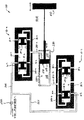
図3は、対立する流体制御システム100の例示的な一実施形態を示す。この実施形態では、2つの複式独立スプールPCVが、単一の作動装置220を制御するように、または単一の作動装置220に制御圧力を与えるように、互いに組み合わせて用いられる。両PCVは、システム100内の圧力を制御するように共に機能する。具体的には、PCV10aは、作動装置のピストン240、結果として負荷を、一方の方向に駆動または変位させるように用いられる流体および圧力を制御するように構成され、一方、PCV10bは、作動装置のピストン240、結果として負荷を、反対の方向に駆動または変位させるように用いられる流体および圧力を制御するように構成される。PCV10aおよび10bのそれぞれは、図1に示され、上述された構造と同様である。
FIG. 3 illustrates an exemplary embodiment of an opposing
作動の際、PCV10aおよび10bは、能動弁状態、非能動弁状態、または非能動受動弁状態(非能動受動性)のいずれかで作動するように構成される。複式PCVは、任意の所与または所定の時間において、ならびに任意の所与または所定の持続期間の間、これらの運転状態の任意の1つになるように、それぞれ個別におよび選択的に制御される。図示の実施形態では、PCV10aは、一方向に、作動装置ピストン240を作動または変位させるように、および負荷250を駆動するように構成される。能動弁状態では、圧力スプール50aが、圧力入口ポート18aおよび圧力出口ポート20aを開くように変位する一方で、戻し入口ポート14aおよび戻し出口ポート16aが閉じられるように、PCV10aのパイロットチャンバ28aのパイロット圧力が操作される。パイロット圧力が、PCVの下流の負荷供給管路210a内の加圧された流体の圧力よりも高く保たれるので、戻しスプール40aは変位しない。
In operation, the PCVs 10a and 10b are configured to operate in either an active valve state, an inactive valve state, or an inactive passive valve state (inactive passive). Duplex PCVs are individually and selectively controlled to be at any one of these operating states at any given or given time and for any given or given duration. The In the illustrated embodiment, the PCV 10a is configured to actuate or displace the
開位置において、圧力スプール50aは、加圧された流体(すなわち、負荷チャンバ234内に作用する負荷圧力よりも高い圧力を有する流体)が、圧力源(図示せず)からシステム100へと入ることができるように機能する。加圧された流体は、圧力入口ポート18aに入り、圧力出口ポート20aを通って、主流体管路200aへと進み、次に負荷供給管路210aに入り、最後に作動装置シリンダ230のチャンバ234へと入る。加圧された流体は、チャンバ234の中へ入ると、作動装置ピストン240の第1の側244に作用する。チャンバ234に入る加圧された流体によって及ぼされる力は、対向側のチャンバ238内に存在している圧力と、摩擦または重力などの負荷に作用する外部の力とによって生成される複合力よりも大きいので、作動装置のピストン240が変位され、それによって、連結されている負荷250を、駆動または変位させる。一実施形態によると、流体制御システム100が、位置に基づいて制御されている場合、負荷が所望の点まで駆動されると、圧力スプール50aを変位し、圧力入口ポート18aおよび圧力出口ポート20aを閉じるように、パイロット圧力が再び操作される。
In the open position, pressure spool 50a allows pressurized fluid (ie, fluid having a pressure higher than the load pressure acting in load chamber 234) to enter
PCV10aが、負荷250を駆動する能動弁状態にあるとき、PCV10bは、非能動弁状態に保たれていてよく、システム100から主戻し貯蔵部(図示せず)へと流体を放出するように、戻し入口ポート14bおよび戻し出口ポート16bが開かれる。
When the PCV 10a is in the active valve state driving the
同様に、PCV10bは、PCV10aの能動弁状態によって引き起こされる方向とは反対側の方向に、作動装置ピストン240を作動または変位し、負荷250を駆動するように構成される。能動弁状態では、圧力スプール50bが、圧力入口ポート18bおよび圧力出口ポート20bを開くように変位する一方で、戻し入口ポート14bおよび戻し出口ポート16bが閉じられるように、PCV10bのパイロットチャンバ28bのパイロット圧力が操作される。パイロット圧力が、PCVの下流の負荷供給管路210b内の加圧された流体の圧力よりも高く保たれるので、戻しスプール40bは変位しない。
Similarly, PCV 10b is configured to actuate or displace
開位置において、圧力スプール50bは、加圧された流体(すなわち、負荷チャンバ238内に作用する負荷圧力よりも高い圧力を有する流体)が、圧力源(図示せず)からシステム100入ることができるように機能する。加圧された流体は、圧力入口ポート18bに入り、圧力出口ポート20bを通って、主流体管路200bへと進み、次に負荷供給管路210bに入り、最後に作動装置シリンダ230のチャンバ238へと入る。加圧された流体がチャンバ238の中へ入ると、作動装置ピストン240の第2の側248に作用する。チャンバ238に入る流体の圧力は、対向側のチャンバ234内に存在している圧力と、摩擦または重力などの負荷に作用する外部の力とによって生成される複合力よりも大きいので、作動装置のピストン240が変位され、それによって、連結されている負荷250を、駆動または変位させる。一実施形態によると、流体制御システム100が、位置に基づいて制御されている場合、負荷が所望の点まで駆動されると、圧力スプール50bを変位し、圧力入口ポート18bおよび圧力出口ポート20bを閉じるように、パイロット圧力が再び操作される。
In the open position, the pressure spool 50b allows pressurized fluid (ie, fluid having a pressure higher than the load pressure acting in the load chamber 238) to enter the
PCV10bが、負荷250を駆動する能動弁状態にあるとき、PCV10aは、非能動弁状態にされており、システム100から主戻し貯蔵部(図示せず)へと流体を放出するように、戻し入口ポート14aおよび戻し出口ポート16aが開かれる。PCV10bの機能は、PCV10aの機能と同様である。
When the PCV 10b is in the active valve state that drives the
理解されるように、PCV10aおよび10bの両方の能動弁状態を選択的および交互に交替して作動させることによって、作動装置ピストン240、および結果として負荷250が、所望のように、双方向の方式で前後に変位または駆動可能であり、各PCVは、作動装置ピストン240の対向する一方向の変位をもたらすように構成される。
As will be appreciated, by selectively and alternately actuating the active valve states of both PCVs 10a and 10b, the
本発明の弁システムおよび対応する流体制御システムの最も有利な特徴は、おそらく、外部的に掛けられる負荷の下で、または一方または両方のPCVによる負荷の能動的な作動の際に生じた運動量などの内在する力の結果として、負荷が自由に振れる、またはぶら下がる能力である。自由に振れる、またはぶら下がる能力は、流体制御システムに圧力制御をもたらすのに用いられる、PCVの特異な構成および設計の結果である。図2に示されるPCVのそれぞれは、非能動の受動状態、または上に定義した揺動モードになることができる。負荷に自由に振れるまたはぶら下がる能力を与えるために、PCV10aおよび10bのそれぞれは、同時に、受動的な作動状態または揺動モードにされる。 The most advantageous features of the valve system and the corresponding fluid control system of the present invention are probably the momentum produced during the active actuation of the load under an externally applied load or by one or both PCVs, etc. The ability of the load to swing or hang freely as a result of its inherent force. The ability to swing or hang freely is a result of the unique configuration and design of the PCV used to provide pressure control to the fluid control system. Each of the PCVs shown in FIG. 2 can be in an inactive passive state, or a swing mode as defined above. In order to give the load the ability to swing or hang freely, each of the PCVs 10a and 10b is simultaneously put into a passive operating or swing mode.
非能動の受動状態にするためには、PCV10aおよび10bのそれぞれの各パイロットチャンバ28aおよび28bのパイロット圧力または制御圧力が、負荷作動装置220によって及ぼされる戻しスプール40a、40b、および圧力スプール50a、50bに作用する負荷圧力またはフィードバック圧力よりも低くなるように、個々に操作および保持される。このパイロット圧力が、スプール40および50に作用する負荷またはフィードバック圧力より低いので、戻しスプール40aおよび40bは、それぞれ、戻し入口ポート14a、16a、および戻し出口ポート14b、16bを開くように変位される。圧力スプール50aおよび50bは、PCV10aおよび10bのそれぞれの中に配置された制限手段のために閉じられたままとなる。
To enter an inactive passive state, the pilot or control pressure of each pilot chamber 28a and 28b of PCV 10a and 10b, respectively, is exerted by return actuator 40a, 40b and pressure spools 50a, 50b. Are individually operated and maintained so as to be lower than the load pressure or feedback pressure acting on them. Since this pilot pressure is lower than the load or feedback pressure acting on
また、PCV10aおよび10bの構成の一部は、戻し出口ポート16aおよび16bの流体連結である。図示のように、PCV10aの戻し出口ポート16aは、戻し管路260および264を介して、PCV10bの戻し出口ポート16bに流体連結される。戻し管路260は、戻し出口ポート16aに流体連結され、そこから、戻し管路264ならびに主戻し貯蔵部(図示せず)に流体連結するように延在する。同様に、戻し管路264は戻し出口ポート16bに流体連結され、そこから、戻し管路260ならびに主戻し貯蔵部に流体連結するように延在する。流れ制御弁272が、戻し流体管路260および264の交差点の下流にあり、システム100から主戻し貯蔵部へと戻る流体の流れを選択的に調整するように構成される。
Part of the configuration of the PCVs 10a and 10b is a fluid connection of the return outlet ports 16a and 16b. As shown, the return outlet port 16a of the PCV 10a is fluidly connected to the return outlet port 16b of the PCV 10b via
2つのPCVの戻し出口ポートを流体連結することによって、ならびに、パイロット圧力を負荷圧力またはフィードバック圧力より低くなるように制御することによって、戻しスプール40aおよび40bを変位し、戻し入口ポート14a、16a、および戻し出口ポート14b、16bを開き、PCV10aおよび10bが、非能動の受動的弁状態、または揺動モードにされる。この状態では、非作動的な力に応答して作動装置のピストン240が前後に変位する(すなわち作動装置は容易に逆向きに駆動可能である)際に、流体が、システム100内において、特に負荷作動装置220、PCV10aおよびPCV10bの間で、前後に分流することができる。たとえば、揺動モードでは、外部の力が負荷250を引いて変位させると、負荷に連結された作動装置のピストン240も、作動装置の負荷シリンダ230内で変位する。負荷250および負荷シリンダ230内の作動装置ピストン240のこの方向への変位が、作動装置ピストン240の変位の方向に負荷シリンダチャンバ234内の流体を変位するように機能する。低い圧縮性を有する変位された流体は、負荷供給管路210aから出て、主流体管路200aへと流れる。主流体管路200aに入ると、変位された流体は、圧力スプール50aが閉位置にあるため、圧力出口ポート20aを通って流れることはできない。したがって、流体は、戻し入口ポート14aを介してPCV10aの中へと強制的に流れ、開いた戻しスプール40aを通過して、戻し出口ポート16aを介してPCV10aから出て、戻し流体管路260に入る。
By fluidly connecting the return outlet ports of the two PCVs and by controlling the pilot pressure to be lower than the load pressure or feedback pressure, the return spools 40a and 40b are displaced and the return inlet ports 14a, 16a, And the return outlet ports 14b, 16b are opened, and the PCVs 10a and 10b are put into an inactive passive valve state, or swing mode. In this state, fluid is transferred within the
流れ制御弁272が閉じられると、主戻し貯蔵部へのアクセスが切断され、流体は、さらに戻し流体管路260から戻し流体管路264へと強制的に流れ出る。ここから、流体は戻し出口ポート16bを介してPCV10bへと流れ、開いた戻しスプール40bを通過し、戻し入口ポート14bを介してPCV10bを出る。戻し入口ポート14bから、流体は主流体管路200bへと流れる。圧力出口ポート20bは、圧力スプール50bが閉鎖位置にあるため閉じられているので、流体は、圧力出口ポート20bを介してPCV10b内へと戻ることはできない。その代わり、流体は負荷供給管路210bに強制的に入り、その後、作動装置ピストン240の反対側の負荷シリンダチャンバ238に入る。
When the
負荷250が反対方向へ作動すると、システム100内の流体は反対方向に流れ、上述の経路を介して戻ることが理解されよう。
It will be appreciated that when the
制御弁272を閉じることの代替として、主戻し貯蔵部が、わずかに加圧されてもよい。主戻し貯蔵部を低い陽圧に保ち、次に、パイロット圧力を主戻し貯蔵部の圧力より下げることで、制御弁272を閉じることと同じ効果が生じ、PCV10a内の油圧液は、主戻し貯蔵部内へと戻る代わりに、戻し管路を介してPCV10bへと流れ、そこから、作動装置のピストン240の反対側のチャンバへと流れる。
As an alternative to closing the
PCV10aおよび10bが、非能動の受動的な弁状態または揺動モードにあるとき、システム100内で流体を前後に変位することが、システム内での流体の分流として本明細書に説明されており、負荷250の自由な振れ、またはぶら下がりを容易にする。理解可能なように、負荷250および負荷250に連結された作動装置のピストン240は、システムからの能動的な入力なくして、外部的に掛けられた負荷の下で動くことができる。言い換えると、外部的に掛けられた力に応答して、負荷および作動装置のピストンの変位を容易にするため、または可能にするために、能動的な入力は必要ない。代わりに、負荷250および作動装置ピストン240は、負荷250に掛けられる力に直接的に応答して、自由に振れる、またはぶら下がることができる。
Displacement of fluid back and forth within
本発明のさらなる利点は、負荷が減速される際に、PCV10aおよび10bの両方を非能動の受動的な弁状態に配置する能力、言い換えると、効率的な制動のためにシステムを揺動モードにする能力である。状況によっては、負荷の能動的な作動を止めることによって、対応する運動量の力を負荷内に引き起こし得る。この運動量の力は(負荷をさらに変位させるのに十分である場合)、PCVを非能動の受動的な弁状態、または揺動モードにすることによって、効率的に縮小され得る。この状態では、PCVと負荷作動装置との間の流体の分流の結果、損になり、それが負荷の運動エネルギーを分散させる。揺動モードにあるときに制動すると、PCVは、負荷が、負荷の能動的な変位量によって与えられる距離を超える距離だけ、受動的に変位できるようにするが、負荷の動きを遅くするか、または抑制するために、高圧供給貯蔵部からの追加の流体は使用されない。 A further advantage of the present invention is the ability to place both PCVs 10a and 10b in an inactive passive valve state when the load is decelerated, in other words, put the system in a rocking mode for efficient braking. Is the ability to In some situations, stopping the active actuation of the load can cause a corresponding momentum force in the load. This momentum force (if sufficient to displace the load further) can be effectively reduced by putting the PCV into an inactive passive valve state, or a rocking mode. In this state, fluid diversion between the PCV and the load actuator results in a loss, which dissipates the kinetic energy of the load. When braking in swing mode, the PCV allows the load to be passively displaced by a distance that exceeds the distance given by the amount of active displacement of the load, but slows the movement of the load, Or, to suppress, no additional fluid from the high pressure supply reservoir is used.
PCVの非能動の受動的な弁状態は、ほとんどの部分では、局所的流体を使用することに留意されたい。「局所的流体」とは、本明細書では、PCV、負荷作動装置、およびその間に延在する任意の流体管路内に含まれる流体であって、主戻し貯蔵部の一部でない流体と定義される。より具体的には、「局所的流体」は、PCVが非能動の受動的弁状態に置かれているとき、主戻し貯蔵部から隔離されているか、または流体的に分離されている流体制御システム内に存在する流体を意味するように意図される。図3に示す実施形態では、局所的流体は、PCV10a、PCV10b、および負荷作動装置220、ならびにこれらを連結している管路(すなわち、負荷供給管路210aおよび210b、主流体管路200aおよび200b、ならびに戻し管路260および264)の中に存在する流体を含む。
Note that the PCV inactive passive valve state uses, for the most part, local fluid. “Local fluid” is defined herein as fluid contained in the PCV, the load actuator, and any fluid lines extending therebetween, and not part of the main return reservoir. Is done. More specifically, the “local fluid” is a fluid control system that is isolated or fluidly isolated from the main return reservoir when the PCV is placed in an inactive passive valve state. It is intended to mean a fluid present within. In the embodiment shown in FIG. 3, the local fluid is PCV 10a, PCV 10b, and
理解可能であるように、図1の作動システム100内の局所的流体は、流れ制御弁272で閉じることによって、主戻し貯蔵部から流体的に分離され得る。しかしながら、制御弁272を閉じることの代わりに、主戻し貯蔵部が、わずかに加圧されてもよい。主戻し貯蔵部を低圧に保ち、次に、パイロット圧力を主戻し貯蔵部の圧力より下げることで、制御弁272を閉じることと同じ効果を達成する。主戻し貯蔵部が加圧されることで、両PCVのパイロット圧力を主戻し貯蔵部の圧力より下げることにより、システムが揺動モードになると、貯蔵部から戻し管路260および264へとわずかな量の逆流があり得る。しかしながら、戻し貯蔵部と作動装置との間の流体の流れの量は、非常にわずかである。
As can be appreciated, local fluid within the
ここで図4を参照すると、図示されているのは、図3に示され、上述された実施形態の代替実施形態である。図4は、流体制御システム100内の圧力を制御するために、単一の作動装置220と組み合わせて使用される複式のPCV10aおよび10bを示す。具体的には、PCV10aは、作動装置ピストン240、結果として負荷250を、一方の方向に駆動または変位するために用いられる流体および圧力を制御するように構成され、一方、PCV10bは、作動装置ピストン240、結果として負荷250を、他方の方向に駆動または変位するために用いられる流体および圧力を制御するように構成される。PCV10aおよび10bのそれぞれは、図1〜3に示され、上述されたものと構造的に同様であるが、図4に示すPCV10aおよび10bのみは、上述され、本明細書に援用される特許に述べられたものなどの、内在する機械式フィードバックシステムを備えている。
Referring now to FIG. 4, illustrated is an alternative embodiment of the embodiment shown in FIG. 3 and described above. FIG. 4 shows dual PCVs 10a and 10b used in combination with a
図示のように、PCV10aは、フィードバックシリンダ304aおよびフィードバックピストン308aからなる、第1の内在する機械式フィードバックシステム300aを備える。PCV10aは、また、やはりフィードバックシリンダ316aおよびフィードバックピストン320aからなる、第2の内在する機械式フィードバックシステム312aを備える。同様に、PCV10bは、フィードバックシリンダ304bおよびフィードバックピストン308bからなる、第1の内在する機械式フィードバックシステム300bを備える。PCV10bは、また、やはりフィードバックシリンダ316bおよびフィードバックピストン320bからなる、第2の内在する機械式フィードバックシステム312bを備える。図3に示すPCV10aおよび10bは、図2に示すPCVと同様の方式で機能するが、図3に示すPCVのみは、流体フィードバックシステムの代わりに機械式フィードバックシステムを用いる。したがって、図2に関する上記の論議は、該当する場合、ここに援用される。 As shown, the PCV 10a includes a first inherent mechanical feedback system 300a consisting of a feedback cylinder 304a and a feedback piston 308a. The PCV 10a also includes a second inherent mechanical feedback system 312a that also consists of a feedback cylinder 316a and a feedback piston 320a. Similarly, the PCV 10b includes a first inherent mechanical feedback system 300b consisting of a feedback cylinder 304b and a feedback piston 308b. The PCV 10b also includes a second inherent mechanical feedback system 312b, also consisting of a feedback cylinder 316b and a feedback piston 320b. The PCVs 10a and 10b shown in FIG. 3 function in a manner similar to the PCV shown in FIG. 2, but only the PCV shown in FIG. 3 uses a mechanical feedback system instead of a fluid feedback system. Accordingly, the above discussion regarding FIG. 2 is incorporated herein, if applicable.
図5は、流体制御システムが上述の圧力制御弁を使用する、本発明の例示的な一実施形態による流体制御システムを示す。より具体的には、流体制御システムは、プーリによって支持された対向する腱によって負荷を駆動するように構成された、それぞれの対立する腱作動装置を作動させるように機能する、2つの複式の独立スプール圧力制御弁を備える。図示のように、流体制御システムは、上記に説明され、図1に示されたPCVと同様の方法で構成された第1のPCV10aを備え、この説明が本明細書に援用される。第1のPCV10aは、負荷作動装置220aを介して負荷376によって及ぼされる負荷圧力と、パイロット弁340から受けたパイロット圧力または制御圧力との間の圧力差に従って、PCVの弁本体内で独立して変位する複式の独立スプール40aおよび50aを備える。
FIG. 5 illustrates a fluid control system according to an exemplary embodiment of the present invention where the fluid control system uses the pressure control valve described above. More specifically, the fluid control system functions as a dual independent, functioning to actuate each opposing tendon actuator configured to drive a load by opposing tendons supported by pulleys. A spool pressure control valve is provided. As shown, the fluid control system includes a first PCV 10a described above and configured in a manner similar to the PCV shown in FIG. 1, the description of which is incorporated herein. The first PCV 10a is independently independent within the valve body of the PCV according to the pressure difference between the load pressure exerted by the
同様に、上記に説明され、図1に示されたPCVと同様の方法でやはり構成された、流体制御システムは、第2のPCV10bを備える。第2のPCVは、負荷作動装置220bを介して負荷376によって及ぼされる負荷圧力と、パイロット弁344から受けたパイロット圧力または制御圧力との間の圧力差に従って、PCVの弁本体内で独立して変位する、複式の独立スプール40bおよび50bを備える。
Similarly, the fluid control system described above and also configured in a manner similar to the PCV shown in FIG. 1 comprises a second PCV 10b. The second PCV is independently independent within the valve body of the PCV according to the pressure difference between the load pressure exerted by the
第1および第2のPCV10aおよび10bは、その戻し出口ポートならびに流体管路260および264を介して互いに流体連結され、流体管路260および264は、また、戻し貯蔵部352と流体連通する。しかしながら、上述のように、PCVが揺動モードで作動されるとき、戻し貯蔵部352への流体の流れを防ぐように弁272が含まれてよい。または、やはり上述のように、戻し貯蔵部は、低い陽圧に保持されてよい。各PCVは、また、その圧力入口ポートを介して互いに流体連結され、圧力入力ポートは、また、圧力源または供給貯蔵部348と流体連通する。当然ながら、当業者は理解するように、PCV10aおよび10bをその圧力入力ポートを介して互いに流体連結するのではなく、別々の供給貯蔵部および戻し貯蔵部が組み込まれてよいか、または、別々の圧力供給管路が使用されてもよい。
The first and second PCVs 10 a and 10 b are fluidly connected to each other via their return outlet ports and
第1のPCV10aは、シリンダ内に配設されたピストン240aを備える第1の負荷作動装置220aを操作および制御するように構成される。第1の負荷作動装置220a、またはより特にピストン240aは、腱360につながれ、腱360は、枢動点380を中心に回転するように構成されたプーリ368によって支持される。
The first PCV 10a is configured to operate and control a first load actuator 220a that includes a piston 240a disposed within the cylinder. The first load actuator 220a, or more particularly the piston 240a, is coupled to a
第2のPCV10bは、シリンダ内に配設されたピストン240bをやはり備える、第2の負荷作動装置220bを操作および制御するように構成される。第2の負荷作動装置220b、またはより特にピストン240bは、第2の腱364につながれ、腱364は、やはりプーリ368によって支持される。腱360および364は、ピストンとプーリ368との間で張力の掛かった状態になるように構成される。腱360および364は、プーリ368の回りに巻かれた複数本の単一の腱(たとえば単一のケーブル)であってよいか、または、それぞれが互いに連結された、および/もしくはプーリ368およびそれぞれの負荷作動装置に連結された、独立した腱(たとえば2つの別々のケーブル)であってもよい。プーリ368は、異なる負荷作動装置の作動に際して、プーリ368が、負荷を前後に駆動するように回転させられるように、負荷376を支持するようにさらに構成される。
The second PCV 10b is configured to operate and control a second load actuator 220b that also includes a piston 240b disposed within the cylinder. The second load actuator 220b, or more particularly the piston 240b, is connected to the
操作に際して、すなわち負荷376を駆動し、その前後の動きを制御するために、異なる作動装置220aおよび220bが作動される。これは、それぞれ、PCV10aおよび10bから、異なる負荷作動装置220aおよび220bへと掛けられる、システム内のパイロット圧力を制御することによって行われる。たとえば、図5を見ると、負荷を逆時計回り方向に駆動するためには、パイロット弁340が、PCV10aのパイロットチャンバに送られるパイロット圧力または制御圧力を上昇させる。ピストン240aに及ぼされる負荷圧力よりもパイロット圧力を上昇させることで、PCV10a内のスプール50aが変位して、圧力源348と流体連通している圧力ポートを開く。すると、加圧された油圧流体が、PCV10aから流体管路210aを介して負荷作動装置220aへ、そしてチャンバ234aへと流れる。上昇した圧力は、負荷圧力に勝ち、シリンダ内のピストン240aをチャンバ開口部から離れるように変位させる。ピストン240aは腱360につながれているので、腱360は、ピストン240aが変位するにつれて引かれ、腱360は、逆時計回り方向にプーリ368を回転させ、したがって、次に、負荷376をやはり逆時計回り方向に回転させる、または、言い換えると、負荷を駆動する。プーリ368が逆時計回り方向に回転させられると、これが腱364を効果的に引き、ピストン240bと腱364は互いにつながれているので、第2の負荷作動装置220b内のピストン240bをそのシリンダ内で変位させる。こうして、負荷作動装置220b内の流体は、流体管路210bを介してチャンバから強制的に出され、第2のPCV10bへとその戻し入口ポートを介して入る。システム内の流体は実質的に圧縮不可能であるので、これは、PCV10bの戻し入口ポートを開くことによってのみ可能である。したがって、パイロット弁340が第1PCV10aへのパイロット圧力を上昇させると、パイロット弁344は、同時に、第2PCV10bへのパイロット圧力を低下させる。第2PCV10bへのパイロット圧力を効果的に低下させることによって、戻しスプール40bが変位し、戻し入口ポートおよび戻し出口ポートが開く。したがって、プーリ368が逆時計回りに回転させられ、ピストン240bが補償するように変位されると、流体は、第2の負荷作動装置220bからPCV10bを介して流れ、戻し貯蔵部352へと戻ることができる。
In operation, that is, to drive the
時計回りの方向にプーリ368を回転させるように流体制御システムを作動するため、したがって、しかるべく負荷を駆動するためには、システムが逆の方式で作動される、すなわち、第2PCV10bのパイロット圧力が上昇される一方で、第1PCV10aのパイロット圧力が低下される。
In order to operate the fluid control system to rotate the
揺動モードでは、PCV10aおよび10bのそれぞれの戻し入口ポートおよび戻し出口ポートを開くように、PCV10aおよび10b両方のパイロット圧力が、個々に下げられ、十分に低いレベルに保持される。それぞれのPCVの戻し出口は、互いに流体連通されている。上述のように、揺動モードでは、負荷作動装置220aまたは220bがいずれも能動的に作動することなく、負荷は、外部のまたは内在する入力に応じて自由に回転する、またはぶら下がることができる。上述の揺動についての論議が、適用可能なところは、本明細書に援用される。揺動モードでは、流体がPCV10aとPCV10bとの間で前後に分流できるので、負荷376は、能動的に作動することなく前後に回転可能である。前後に分流する流体は、戻し貯蔵部352に至る戻し管路内の弁272を閉じることのみによって、局所的流体にされる。
In the rocking mode, the pilot pressures of both PCVs 10a and 10b are individually lowered and held at a sufficiently low level to open the respective return inlet and return outlet ports of PCVs 10a and 10b. The return outlets of each PCV are in fluid communication with each other. As described above, in the oscillating mode, the load can freely rotate or hang in response to external or intrinsic input, without either load actuator 220a or 220b being actively activated. Where applicable, the discussion about rocking described above is incorporated herein. In the rocking mode, fluid can be shunted back and forth between PCV 10a and PCV 10b, so load 376 can rotate back and forth without actively operating. The fluid diverted back and forth is made a local fluid only by closing the
図5のように構成された流体制御システムは、従来の関連するシステムに追加の有意な利点を提供する。まず、この機構は、機械式リンク機構を備えた複式作動式のリニア作動装置を用いて達成される機構と比較して、より大きい可動域をもたらす。第2に、作動装置はまた、負荷が動かされている間、両方の腱が張力の下に保たれる(互いに収縮する)ので、バックラッシュを効果的に排除するやり方で作動されることができる。上述のように制御機構を揺動モードにする能力と組み合わせたとき、両方の特徴は、ロボットの腕または脚の動きを制御するように使用される作動環境などの、本明細書に述べられた例示的な流体制御システムのための例示的な作動環境における改善された性能をもたらし、腕または脚は、ぶら下がることのできる結果として、より自然な、生きているような動きをもたらすことができる。PCVの対によってもたらされる受動的な制動能力を利用することによって、システムの性能および効率が改善される。 A fluid control system configured as in FIG. 5 provides an additional significant advantage over a conventional related system. First, this mechanism provides a greater range of motion compared to a mechanism achieved using a dual-acting linear actuator with a mechanical linkage. Second, the actuator can also be operated in a manner that effectively eliminates backlash, since both tendons are kept under tension (contracted together) while the load is moved. it can. When combined with the ability to put the control mechanism in a rocking mode as described above, both features are described herein, such as the operating environment used to control the movement of the robot arm or leg. It provides improved performance in an exemplary operating environment for an exemplary fluid control system, and an arm or leg can result in a more natural, lively movement as a result of being able to hang. By utilizing the passive braking capability provided by the PCV pair, the performance and efficiency of the system is improved.
前述の詳細な説明は、特定の例示的な実施形態を参照して本発明を説明する。しかしながら、添付の特許請求の範囲に述べられる本発明の範囲から逸脱することなく、様々な修正および変更が行われ得ることが理解されるであろう。詳細な説明および添付の図面は、制限的ではなく、単に例示的であるのみと考えられるべきであり、存在する場合は、このようなすべての修正例または変形例は、本明細書に説明され述べられた本発明の範囲内にあることが意図される。 The foregoing detailed description describes the invention with reference to specific exemplary embodiments. However, it will be understood that various modifications and changes may be made without departing from the scope of the present invention as set forth in the appended claims. The detailed description and accompanying drawings are to be regarded as illustrative rather than restrictive, and all such modifications or variations, if any, are described herein. It is intended to be within the scope of the described invention.
より具体的には、本発明の例示的な実施形態が本明細書に説明されてきたが、上述の詳細な説明に基づいて当業者によって理解されるように、本発明は、これらの実施形態に制限されず、修正、省略、(たとえば様々な実施形態にわたる態様の)組合せ、改造、および/または変更を有する任意のすべての実施形態を含む。特許請求の範囲における限定は、特許請求の範囲において用いられる言葉に基づいて広義に解釈されるべきであり、上述の詳細な説明においてまたは用途の遂行の際に説明された実施例に限定されるべきではなく、これらの実施例は、非排他的であると解釈されるべきである。たとえば、本開示において、用語「好ましくは」は、非排他的であり、「好ましいが、これに限定されない」ということを意味するように意図される。任意の方法または工程の請求項に引用された任意のステップは、任意の順序で実行可能であり、請求項に示される順序には限定されない。ミーンズプラスファンクションまたはステッププラスファンクションの限定は、特定の請求項の限定に対して、a)「〜する手段(means for)」または「〜するステップ(step for)」と明示されており、b)対応する機能が明示されているという、これら条件のすべてが、その限定に対して存在する場合のみに用いられる。ミーンズプラスファンクションを支持する構造、材料または行為は、本明細書の説明に明示される。したがって、本発明の範囲は、上記の説明および例によってではなく、単に、添付の特許請求の範囲およびその法律上の均等物のみによって決定されるべきである。 More specifically, exemplary embodiments of the present invention have been described herein, but as will be understood by those skilled in the art based on the foregoing detailed description, the present invention is not limited to these embodiments. And includes any and all embodiments having modifications, omissions, combinations (eg, aspects of the various embodiments), modifications, and / or changes. The limitations in the claims should be interpreted broadly based on the terms used in the claims, and are limited to the embodiments described in the above detailed description or in carrying out the application. These examples should not be construed as non-exclusive. For example, in this disclosure, the term “preferably” is intended to mean non-exclusive and “preferably, but not limited to.” Any steps recited in any method or process claims may be executed in any order and are not limited to the order presented in the claims. Means-plus-function or step-plus-function limitations are specified as a) “means for” or “step for” for specific claim limitations; b) All of these conditions where the corresponding function is specified are only used if they exist for that limitation. The structure, material or action that supports the means plus function will be specified in the description herein. Accordingly, the scope of the invention should be determined solely by the appended claims and their legal equivalents, rather than by the foregoing description and examples.
Claims (10)
負荷に連結された作動装置ピストンを有する負荷作動装置であって、前記負荷の能動的および受動的な変位を容易にするように構成された負荷作動装置と、
前記負荷作動装置を用いて操作可能であり、前記負荷作動装置の前記ピストンの第1の側に制御圧力を与え、前記作動装置ピストンおよび前記負荷の能動的および受動的な変位を容易にするように構成された第1の圧力制御弁と、
前記負荷作動装置を用いて操作可能であり、前記負荷作動装置の前記ピストンの第2の側に制御圧力を与え、前記第1の圧力制御弁によって容易にされた方向とは反対側の方向への前記作動装置ピストンおよび前記負荷の能動的および受動的な変位を容易にするように構成された第2の圧力制御弁とを備え、
前記第1および第2の圧力制御弁が、前記作動装置ピストンおよび前記負荷をそれぞれの方向に選択的に駆動する能動弁状態と、前記作動装置ピストンおよび前記負荷が、前記負荷に作用する非作動的な力に応答して受動的に変位できるように、局所的流体が前記第1の圧力制御弁と前記第2の圧力制御弁との間で前後に分流する受動弁状態とを有する流体制御システム。 In a fluid control system using opposing pressure controls,
A load actuator having an actuator piston coupled to a load, the load actuator configured to facilitate active and passive displacement of the load;
Operable with the load actuator to apply a control pressure to the first side of the piston of the load actuator to facilitate active and passive displacement of the actuator piston and the load. A first pressure control valve configured to:
Operable using the load actuator, applying a control pressure to the second side of the piston of the load actuator and in a direction opposite to the direction facilitated by the first pressure control valve. Said actuator piston and a second pressure control valve configured to facilitate active and passive displacement of said load;
An active valve state in which the first and second pressure control valves selectively drive the actuator piston and the load in respective directions; and an inactive state in which the actuator piston and the load act on the load Fluid control having a passive valve state in which a local fluid is shunted back and forth between the first pressure control valve and the second pressure control valve so that it can be passively displaced in response to a general force system.
弁本体の内部空洞部と流体連通する戻し入口ポートおよび戻し出口ポート、圧力入口ポートおよび圧力出口ポート、ならびに第1および第2のフィードバックポートが中に形成された弁本体と、
前記弁本体内で自由に支持され、前記戻し入口ポートおよび戻し出口ポートを介する流体の流れを調整するように構成された戻しスプールと、
前記戻しスプールから独立しており、前記弁本体内の前記戻しスプールの反対側で自由に支持された圧力スプールであって、前記圧力入口ポートおよび圧力出口ポートを介する流体の流れを調整するように構成された圧力スプールと、
前記戻しスプールおよび圧力スプールの対向する側に同時に作用するパイロット圧力とフィードバック圧力との間に生じる圧力差に応じて、前記戻しスプールおよび圧力スプールを変位させるように構成された内在する圧力フィードバックシステムであって、前記圧力差を分散させ、前記パイロット圧力および前記フィードバック圧力を等しくするように構成された内在する圧力フィードバックシステムと、
前記弁本体内に配置され、様々な弁状態における前記弁本体内の前記戻しスプールおよび圧力スプールの位置の制限を確立するように構成された制限手段とをそれぞれ備える、請求項1に記載の流体制御システム。 Each of the first and second pressure control valves is
A valve body having a return inlet port and return outlet port in fluid communication with an internal cavity of the valve body, a pressure inlet port and a pressure outlet port, and first and second feedback ports formed therein;
A return spool supported freely within the valve body and configured to regulate fluid flow through the return inlet port and return outlet port;
A pressure spool independent of the return spool and freely supported on the opposite side of the return spool in the valve body so as to regulate the flow of fluid through the pressure inlet port and the pressure outlet port A configured pressure spool;
An inherent pressure feedback system configured to displace the return spool and the pressure spool in response to a pressure difference between a pilot pressure and a feedback pressure acting simultaneously on opposite sides of the return spool and the pressure spool; An inherent pressure feedback system configured to distribute the pressure differential and equalize the pilot pressure and the feedback pressure;
The fluid of claim 1, each comprising a restricting means disposed within the valve body and configured to establish restrictions on the position of the return and pressure spools within the valve body in various valve states. Control system.
前記第1の負荷作動装置に対立し、前記負荷にやはり連結された作動装置ピストンを有する第2の負荷作動装置であって、前記負荷の反対方向への能動的および受動的な変位を容易にするように構成された第2の負荷作動装置と、
前記第1の負荷作動装置の前記作動装置ピストンおよび前記負荷の能動的および受動的な変位を遂行する制御圧力を与えるように、前記第1の負荷作動装置を用いて操作可能である第1の圧力制御弁と、
制御圧力を与えて前記第2の負荷作動装置の前記作動装置ピストンおよび前記負荷の能動的および受動的な変位を遂行するように、前記第2の負荷作動装置を用いて操作可能である第2の圧力制御弁とを備える流体制御システムにおいて、
前記第1および第2の圧力制御弁が、前記第1および第2の負荷作動装置の前記作動装置ピストンを、それぞれ反対方向に選択的に駆動する能動弁状態と、前記第1および第2の負荷作動装置の前記作動装置ピストンが、前記負荷に作用する非作動的な力に応答して受動的に変位できるように、局所的流体が前記第1の圧力制御弁と前記第2の圧力制御弁との間で前後に分流する受動弁状態とを有する流体制御システム。 A first load actuator having an actuator piston coupled to a load, the first load actuator configured to facilitate active and passive displacement of the load;
A second load actuator that opposes the first load actuator and has an actuator piston that is also coupled to the load, facilitating active and passive displacement in the opposite direction of the load. A second load actuating device configured to:
The first load actuator is operable with the first load actuator to provide a control pressure that performs active and passive displacement of the actuator piston and the load of the first load actuator. A pressure control valve;
A second operable by the second load actuator to provide a control pressure to effect active and passive displacement of the actuator piston of the second load actuator and the load. A fluid control system comprising a pressure control valve of
An active valve state in which the first and second pressure control valves selectively drive the actuator pistons of the first and second load actuators in opposite directions, respectively, and the first and second Local fluid is allowed to displace passively in response to non-actuating forces acting on the load so that the local fluid is in the first pressure control valve and the second pressure control. A fluid control system having a passive valve state that shunts back and forth with the valve.
弁本体の内部空洞部と流体連通する戻し入口ポートおよび戻し出口ポート、圧力入口ポートおよび圧力出口ポート、ならびに第1および第2のフィードバックポートが中に形成された弁本体と、
前記弁本体内で自由に支持され、前記戻し入口ポートおよび戻し出口ポートを介する流体の流れを調整するように構成された戻しスプールと、
前記戻しスプールから独立しており、前記弁本体内の前記戻しスプールの反対側で自由に支持された圧力スプールであって、前記圧力入口ポートおよび圧力出口ポートを介する流体の流れを調整するように構成された圧力スプールと、
前記戻しスプールおよび圧力スプールの対向する側に同時に作用するパイロット圧力とフィードバック圧力との間に生じる圧力差に応じて、前記戻しスプールおよび圧力スプールを変位させるように構成された内在する圧力フィードバックシステムであって、前記圧力差を分散させ、前記パイロット圧力および前記フィードバック圧力を等しくするように構成された内在する圧力フィードバックシステムと、
前記弁本体内に配置され、様々な弁状態における前記弁本体内の前記戻しスプールおよび圧力スプールの位置の制限を確立するように構成される制限手段とをそれぞれ備える、請求項6に記載の流体制御システム。 Each of the first and second pressure control valves is
A valve body having a return inlet port and return outlet port in fluid communication with an internal cavity of the valve body, a pressure inlet port and a pressure outlet port, and first and second feedback ports formed therein;
A return spool supported freely within the valve body and configured to regulate fluid flow through the return inlet port and return outlet port;
A pressure spool independent of the return spool and freely supported on the opposite side of the return spool in the valve body so as to regulate the flow of fluid through the pressure inlet port and the pressure outlet port A configured pressure spool;
An inherent pressure feedback system configured to displace the return spool and the pressure spool in response to a pressure difference between a pilot pressure and a feedback pressure acting simultaneously on opposite sides of the return spool and the pressure spool; An inherent pressure feedback system configured to distribute the pressure differential and equalize the pilot pressure and the feedback pressure;
7. A fluid according to claim 6, each comprising restriction means disposed within the valve body and configured to establish restrictions on the position of the return and pressure spools within the valve body in various valve states. Control system.
独立した第1の圧力スプールおよび戻しスプールを備えて構成される第1の圧力制御弁を設けるステップであって、前記第1の圧力スプールおよび戻しスプールが、第1のパイロット圧力および第1の負荷圧力によって力を及ぼされるステップと、
独立した第2の圧力スプールおよび戻しスプールを備えて構成される第2の圧力制御弁を設けるステップであって、前記第2の圧力スプールおよび戻しスプールが、第2のパイロット圧力および第2の負荷圧力によって力を及ぼされ、前記第1および第2のパイロット圧力が互いに独立して作用するステップと、
負荷を作動させるように構成された負荷作動装置を、前記第1の圧力制御弁および前記第2の圧力制御弁に連結するステップであって、前記第1および第2の圧力制御弁が対立しているステップと、
前記負荷を異なる方向に作動させるように前記第1および第2の圧力制御弁をそれぞれ操作するステップと、
前記第1および第2の圧力制御弁のぞれぞれの戻し入口ポートおよび戻し出口ポートを開くように前記第1および第2の戻しスプールを変位させるために、前記第1および第2のパイロット圧力を前記第1および第2の負荷圧力よりもそれぞれ低くなるように下げるステップと、
前記第1および第2の圧力制御弁と前記負荷作動装置との間で前記それぞれの戻し入口ポートおよび戻し出口ポートを介して流体が前後に分流し、それによって、前記負荷作動装置の作動装置ピストンが能動的な入力なくして受動的に変位される非能動受動性の弁状態を開始するステップとを含む、方法。 In a method of operating a fluid control system configured to drive a load,
Providing a first pressure control valve configured with independent first pressure spool and return spool, wherein the first pressure spool and return spool are provided with a first pilot pressure and a first load; A step exerted by pressure;
Providing a second pressure control valve comprising an independent second pressure spool and return spool, wherein the second pressure spool and return spool have a second pilot pressure and a second load. Exerted by pressure, and wherein the first and second pilot pressures act independently of each other;
Connecting a load actuation device configured to actuate a load to the first pressure control valve and the second pressure control valve, wherein the first and second pressure control valves conflict. And steps
Respectively operating the first and second pressure control valves to actuate the load in different directions ;
The first and second pilots for displacing the first and second return spools to open the respective return inlet and return outlet ports of the first and second pressure control valves. Reducing the pressure to be lower than each of the first and second load pressures;
Fluid is shunted back and forth between the first and second pressure control valves and the load actuator via the respective return inlet and return outlet ports, thereby providing an actuator piston for the load actuator. Initiating an inactive passive valve state that is passively displaced without active input .
独立した第1の圧力スプールおよび戻しスプールを備えて構成される第1の圧力制御弁を設けるステップであって、前記第1の圧力スプールおよび戻しスプールが、第1のパイロット圧力および第1の負荷圧力によって力を及ぼされるステップと、
独立した第2の圧力スプールおよび戻しスプールを備えて構成される第2の圧力制御弁を設けるステップであって、前記第2の圧力スプールおよび戻しスプールが、第2のパイロット圧力および第2の負荷圧力によって力を及ぼされ、前記第1および第2のパイロット圧力が互いに独立して作用するステップと、
負荷を作動させるように構成された第1の負荷作動装置を、前記第1の圧力制御弁に連結するステップと、
前記負荷を作動させるように構成された第2の負荷作動装置を、前記第2の圧力制御弁に連結するステップであって、前記第2の負荷作動装置が前記第1の負荷作動装置に対立しているステップと、
前記負荷を異なる方向に作動させるように前記第1および第2の圧力制御弁をそれぞれ操作するステップと、
前記第1および第2の圧力制御弁のそれぞれの入口ポートおよび出口ポートを開くように前記第1および第2の戻しスプールを変位させるために、前記第1および第2のパイロット圧力を前記第1および第2の負荷圧力よりもそれぞれ低くなるように下げるステップと、
前記第1および第2の圧力制御弁と前記第1および第2の負荷作動装置との間で前記それぞれの戻し入口ポートおよび戻し出口ポートを介して流体が前後に分流し、それによって、前記第1および第2の負荷作動装置のそれぞれの作動装置ピストンが能動的な入力なくして受動的に変位される非能動受動性の弁状態を開始するステップとを含む、方法。 In a method of operating a fluid control system configured to drive a load,
Providing a first pressure control valve configured with independent first pressure spool and return spool, wherein the first pressure spool and return spool are provided with a first pilot pressure and a first load; A step exerted by pressure;
Providing a second pressure control valve comprising an independent second pressure spool and return spool, wherein the second pressure spool and return spool have a second pilot pressure and a second load. Exerted by pressure, and wherein the first and second pilot pressures act independently of each other;
Coupling a first load actuator configured to actuate a load to the first pressure control valve;
Connecting a second load actuation device configured to actuate the load to the second pressure control valve, wherein the second load actuation device opposes the first load actuation device. Step and
Respectively operating the first and second pressure control valves to actuate the load in different directions ;
In order to displace the first and second return spools to open the respective inlet and outlet ports of the first and second pressure control valves, the first and second pilot pressures are set to the first and second pilot pressures, respectively. And lowering each so as to be lower than the second load pressure,
Fluid is shunted back and forth between the first and second pressure control valves and the first and second load actuators via the respective return inlet port and return outlet port, thereby Initiating an inactive passive valve state in which the actuator piston of each of the first and second load actuators is passively displaced without active input .
Applications Claiming Priority (3)
| Application Number | Priority Date | Filing Date | Title |
|---|---|---|---|
| US90424507P | 2007-02-28 | 2007-02-28 | |
| US60/904,245 | 2007-02-28 | ||
| PCT/US2008/055347 WO2008106611A1 (en) | 2007-02-28 | 2008-02-28 | Antagonistic fluid control system for active and passive actuator operation |
Publications (3)
| Publication Number | Publication Date |
|---|---|
| JP2010520418A JP2010520418A (en) | 2010-06-10 |
| JP2010520418A5 JP2010520418A5 (en) | 2011-04-28 |
| JP5232177B2 true JP5232177B2 (en) | 2013-07-10 |
Family
ID=39473304
Family Applications (1)
| Application Number | Title | Priority Date | Filing Date |
|---|---|---|---|
| JP2009551856A Expired - Fee Related JP5232177B2 (en) | 2007-02-28 | 2008-02-28 | Opposing fluid control systems for active and passive actuation of actuators |
Country Status (4)
| Country | Link |
|---|---|
| US (1) | US8061261B2 (en) |
| EP (1) | EP2122185A1 (en) |
| JP (1) | JP5232177B2 (en) |
| WO (1) | WO2008106611A1 (en) |
Families Citing this family (3)
| Publication number | Priority date | Publication date | Assignee | Title |
|---|---|---|---|---|
| WO2008106618A1 (en) | 2007-02-28 | 2008-09-04 | Raytheon Sarcos, Llc | Fluid control system having selective recruitable actuators |
| DE102012017714A1 (en) * | 2012-09-07 | 2014-03-13 | Hoerbiger Automatisierungstechnik Holding Gmbh | Regulated proportional three-way valve unit |
| FI128135B (en) * | 2017-10-20 | 2019-10-31 | Pneumaxpert Oy | Arrangement with oscillating cylinder |
Family Cites Families (87)
| Publication number | Priority date | Publication date | Assignee | Title |
|---|---|---|---|---|
| US204828A (en) | 1878-06-11 | Improvement | ||
| US2861550A (en) | 1952-10-28 | 1958-11-25 | Westinghouse Electric Corp | Hydraulic power control valve |
| FR1104952A (en) | 1954-05-19 | 1955-11-25 | Rech Etudes Production Sarl | Fluid motor, clearance-free |
| DE1053462B (en) | 1958-02-13 | 1959-03-26 | Wagner & Co Werkzeugmaschinenf | Oil hydraulic sheet metal bending press for long carriers u. like |
| GB997756A (en) | 1964-06-22 | 1965-07-07 | Daimler Benz Ag | Improvements relating to hydraulic servo devices on motor vehicles |
| FR1524697A (en) * | 1966-07-06 | 1968-05-10 | Hydraulic Unit Specialities Co | Control valve mechanism |
| US3583422A (en) | 1967-10-19 | 1971-06-08 | Zahnradfabrik Friedrichshafen | Valve construction for controlled pressure buildup in fluid-operated brake or clutch |
| DE1916266A1 (en) | 1968-05-21 | 1970-10-08 | Bbc Brown Boveri & Cie | Electrohydraulic actuator |
| GB1214947A (en) | 1968-08-17 | 1970-12-09 | Girling Ltd | Fluid pressure control valve |
| US3566919A (en) | 1969-01-24 | 1971-03-02 | Pneumo Dynamics Corp | Hydraulic servo valve with pressure feedback |
| GB1245662A (en) | 1969-03-31 | 1971-09-08 | Aida Tekkosho Kk | An article transfer apparatus |
| BE789975A (en) | 1971-10-12 | 1973-02-01 | Sanders Associates Inc | PRESSURE AND FLOW CONTROL VALVE |
| JPS5252260Y2 (en) * | 1972-03-21 | 1977-11-28 | ||
| DE2242022C3 (en) | 1972-08-26 | 1980-11-20 | Integral Hydraulik & Co, 4000 Duesseldorf | Pressure medium sequence control for power steering or the like |
| US4069843A (en) | 1973-04-02 | 1978-01-24 | International Harvester Company | Clutch cylinder circuit and charging valve therefor |
| US3894712A (en) | 1973-07-06 | 1975-07-15 | Parker Hannifin Corp | Excess flow servo valve |
| JPS5060615A (en) | 1973-09-28 | 1975-05-24 | ||
| US3882551A (en) | 1974-01-09 | 1975-05-13 | Battelle Memorial Institute | Artificial muscle |
| US4067357A (en) | 1974-06-14 | 1978-01-10 | Herion-Werke Kg | Pilot-operated directional control valve |
| DE2642804C2 (en) | 1976-09-23 | 1982-12-23 | Daimler-Benz Ag, 7000 Stuttgart | Automatic gear change transmission with a secondary servo power generator for the emergency supply of servo power units of the transmission control and shifting |
| DE2654366C2 (en) | 1976-12-01 | 1984-08-23 | Gebr. Claas, 4834 Harsewinkel | Hydraulic valve device |
| DE2710001A1 (en) | 1977-03-08 | 1978-09-14 | Daimler Benz Ag | PRESSURE RELIEF VALVE FOR THE WORKING PRESSURE OF A POWER STEERING |
| US4211147A (en) | 1977-06-30 | 1980-07-08 | International Business Machines Corporation | Servo-control valve for a linear hydraulic motor |
| US4131130A (en) | 1977-07-18 | 1978-12-26 | Sperry Rand Corporation | Pneumatic pressure control valve |
| US4142612A (en) | 1977-09-21 | 1979-03-06 | General Motors Corporation | Servo motor with differential pressure controlled and actuated release valve |
| US4203465A (en) | 1979-03-27 | 1980-05-20 | General Motors Corporation | Precision pressure control valve |
| WO1981000600A1 (en) | 1979-08-30 | 1981-03-05 | Caterpillar Tractor Co | Lock valve with variable length piston and hydraulic system for a work implement using the same |
| US4348159A (en) | 1980-01-07 | 1982-09-07 | Rexnord Inc. | Convertible pump servo-valve control |
| US4362018A (en) | 1980-06-12 | 1982-12-07 | Kobe Steel, Ltd. | Hydraulic rotation control circuit |
| JPS57144344A (en) | 1981-03-02 | 1982-09-06 | Hitachi Constr Mach Co Ltd | Flushing valve |
| DE3114437C2 (en) | 1981-04-09 | 1989-10-12 | Mannesmann Rexroth GmbH, 8770 Lohr | Pressure control valve |
| US4422293A (en) | 1981-06-12 | 1983-12-27 | The Bendix Corporation | Closed-center hydraulic servo apparatus |
| ZA825477B (en) | 1981-08-21 | 1983-06-29 | Sperry Corp | Hydraulic control system |
| EP0099930B1 (en) | 1982-01-16 | 1989-10-11 | Ebara Corporation | Pressure control valve and oil supply device using said valve |
| FR2525292B1 (en) * | 1982-04-19 | 1986-12-19 | Chatelin Jacques | HYDRAULIC SERVO-MOTOR |
| US4602481A (en) | 1983-09-26 | 1986-07-29 | The Boeing Company | Fluid actuator for binary selection of output force |
| US4714459A (en) | 1985-12-23 | 1987-12-22 | Cordis Corporation | Three stage intracranial pressure control valve |
| FR2593265B1 (en) | 1986-01-17 | 1988-04-22 | Rexroth Sigma | PRESSURE HYDRAULIC FLUID DISTRIBUTOR |
| US4674539A (en) | 1986-02-20 | 1987-06-23 | Sloate Harry M | Rotary servo valve |
| US4657042A (en) | 1986-04-07 | 1987-04-14 | Snap-Tite, Inc. | Pressure modulation device for hydraulic systems |
| GB2192941B (en) * | 1986-07-25 | 1990-10-03 | Rolls Royce Plc | A variable area aircraft air intake |
| JP2662950B2 (en) | 1986-12-17 | 1997-10-15 | 富士重工業株式会社 | Hydraulic control device |
| US4774976A (en) | 1987-09-23 | 1988-10-04 | Applied Power Inc. | Modulating hydraulic pressure control valve and assembly method therefor |
| JPH0168982U (en) | 1987-10-26 | 1989-05-08 | ||
| JPH0241874U (en) | 1988-09-14 | 1990-03-22 | ||
| JPH0454352Y2 (en) | 1989-08-29 | 1992-12-21 | ||
| US4941508A (en) | 1989-12-28 | 1990-07-17 | Dana Corporation | Force balanced hydraulic spool valve |
| US5011180A (en) | 1990-02-02 | 1991-04-30 | The University Of British Columbia | Digital suspension system |
| GB2240609B (en) | 1990-02-02 | 1993-11-24 | Ferranti Int Plc | Fluid control valve |
| US5103866A (en) | 1991-02-22 | 1992-04-14 | Foster Raymond K | Poppet valve and valve assemblies utilizing same |
| JPH0599316A (en) | 1991-10-07 | 1993-04-20 | Toyota Motor Corp | Speed change control device for automatic transmission |
| US5282460A (en) | 1992-01-06 | 1994-02-01 | Joyce Ann Boldt | Three axis mechanical joint for a power assist device |
| US5317953A (en) | 1992-05-26 | 1994-06-07 | Earth Tool Corporation | Neutral-centering valve control system |
| GB9211898D0 (en) | 1992-06-05 | 1992-07-15 | Vickers Systems Ltd | Two-stage hydraulic valves |
| WO1994010457A1 (en) | 1992-10-30 | 1994-05-11 | Bw/Ip International, Inc. | Pressure control valve for a hydraulic actuator |
| JPH06249210A (en) * | 1993-02-26 | 1994-09-06 | Mitsubishi Heavy Ind Ltd | Hydraulic equipment tuning control device |
| US5499320A (en) | 1993-03-24 | 1996-03-12 | The United States Of America As Represented By The Administrator Of The National Aeronautics And Space Administration | Extended task space control for robotic manipulators |
| JPH0777275A (en) | 1993-09-08 | 1995-03-20 | Jatco Corp | Hydraulic controller of automatic transmission |
| DE4447543C2 (en) | 1994-06-28 | 1997-04-17 | Daimler Benz Ag | Servo valve arrangement |
| JP3293455B2 (en) | 1996-04-04 | 2002-06-17 | アイシン・エィ・ダブリュ株式会社 | Control device for automatic transmission |
| JPH09287654A (en) | 1996-04-19 | 1997-11-04 | Aisin Aw Co Ltd | Control device for automatic transmission |
| US5872893A (en) | 1996-07-25 | 1999-02-16 | Honda Giken Kogyo Kabushiki Kaisha | Gait generation system of legged mobile robot |
| JP3047821B2 (en) | 1996-08-29 | 2000-06-05 | 双葉電子工業株式会社 | Fuel pressure control valve for model engine |
| KR100470318B1 (en) | 1997-06-11 | 2005-07-01 | 고요 세이코 가부시키가이샤 | Servovalve for Power Auxiliary Steering Gears |
| US6067892A (en) | 1998-03-18 | 2000-05-30 | Erickson; Joel R. | Artificial muscle actuator assembly |
| US6269733B1 (en) | 1999-04-30 | 2001-08-07 | Dennis K. Reust | Force servo actuator with asymmetric nonlinear differential hydraulic force feedback |
| JP3615702B2 (en) | 1999-11-25 | 2005-02-02 | ソニー株式会社 | Motion control device and motion control method for legged mobile robot, and legged mobile robot |
| US6463959B2 (en) | 2000-02-10 | 2002-10-15 | Luk Lamellen Und Kupplungsbau Beteiligungs Kg | Pressure control valve |
| DE10006141A1 (en) * | 2000-02-11 | 2001-09-06 | Zf Lenksysteme Gmbh | Electro-hydraulic control device |
| DE10019254C2 (en) | 2000-04-18 | 2002-04-25 | Brueninghaus Hydromatik Gmbh | Pressure control valve |
| JP4178736B2 (en) * | 2000-08-30 | 2008-11-12 | 株式会社デンソー | Table feeding system |
| US6467264B1 (en) * | 2001-05-02 | 2002-10-22 | Husco International, Inc. | Hydraulic circuit with a return line metering valve and method of operation |
| US7153242B2 (en) | 2001-05-24 | 2006-12-26 | Amit Goffer | Gait-locomotor apparatus |
| JP4188607B2 (en) | 2001-06-27 | 2008-11-26 | 本田技研工業株式会社 | Method for estimating floor reaction force of bipedal mobile body and method for estimating joint moment of bipedal mobile body |
| US7217247B2 (en) | 2002-09-23 | 2007-05-15 | Honda Giken Kogyo Kabushiki Kaisha | Gravity compensation method in a human assist system and a human assist system with gravity compensation control |
| JP3674778B2 (en) | 2001-09-27 | 2005-07-20 | 本田技研工業株式会社 | Leg joint assist device for legged mobile robot |
| JP3569764B2 (en) | 2001-11-19 | 2004-09-29 | 独立行政法人 科学技術振興機構 | Bipod walking type moving device, its walking control device, and walking control method |
| US6966882B2 (en) | 2002-11-25 | 2005-11-22 | Tibion Corporation | Active muscle assistance device and method |
| US7308848B2 (en) * | 2004-12-02 | 2007-12-18 | Sarcos Investments Lc | Pressure control valve having intrinsic feedback system |
| US7284471B2 (en) | 2004-12-02 | 2007-10-23 | Sarcos Investments Lc | Pressure control valve having intrinsic mechanical feedback system |
| US7313463B2 (en) | 2005-03-31 | 2007-12-25 | Massachusetts Institute Of Technology | Biomimetic motion and balance controllers for use in prosthetics, orthotics and robotics |
| US20060249315A1 (en) | 2005-03-31 | 2006-11-09 | Massachusetts Institute Of Technology | Artificial human limbs and joints employing actuators, springs, and variable-damper elements |
| JP4595727B2 (en) | 2005-07-22 | 2010-12-08 | ソニー株式会社 | External force estimation system, external force estimation method, and computer program |
| DE102005037619B4 (en) * | 2005-08-09 | 2020-07-09 | Brueninghaus Hydromatik Gmbh | Control valve unit with change stop |
| US7190141B1 (en) | 2006-01-27 | 2007-03-13 | Villanova University | Exoskeletal device for rehabilitation |
| US7409825B2 (en) * | 2006-08-02 | 2008-08-12 | Husco International, Inc. | Hydraulic system with a cylinder isolation valve |
| WO2008106618A1 (en) | 2007-02-28 | 2008-09-04 | Raytheon Sarcos, Llc | Fluid control system having selective recruitable actuators |
-
2008
- 2008-02-28 JP JP2009551856A patent/JP5232177B2/en not_active Expired - Fee Related
- 2008-02-28 WO PCT/US2008/055347 patent/WO2008106611A1/en active Application Filing
- 2008-02-28 EP EP08731006A patent/EP2122185A1/en not_active Withdrawn
- 2008-02-28 US US12/074,260 patent/US8061261B2/en not_active Expired - Fee Related
Also Published As
| Publication number | Publication date |
|---|---|
| WO2008106611A1 (en) | 2008-09-04 |
| US8061261B2 (en) | 2011-11-22 |
| EP2122185A1 (en) | 2009-11-25 |
| JP2010520418A (en) | 2010-06-10 |
| US20080216644A1 (en) | 2008-09-11 |
Similar Documents
| Publication | Publication Date | Title |
|---|---|---|
| JP5460335B2 (en) | Fluid control system having a selectively activatable actuator | |
| JP5232227B2 (en) | Pressure control valve with asymmetric valve actuation structure | |
| US7509905B2 (en) | Pressure control valve having intrinsic mechanical feedback system | |
| JP6629229B2 (en) | Transmission control unit | |
| US7308848B2 (en) | Pressure control valve having intrinsic feedback system | |
| WO2014034510A1 (en) | Actuator | |
| JPH0448962B2 (en) | ||
| JP2012527586A (en) | Hydraulic switching mechanism for mobile hydraulic device, mobile hydraulic machine and valve unit | |
| JP5232177B2 (en) | Opposing fluid control systems for active and passive actuation of actuators | |
| JP2004353859A (en) | Actuator oil level variable control device for construction heavy equipment | |
| JPH09317879A (en) | Back pressure control circuit for hydraulic driving device | |
| JP6788395B2 (en) | Cylinder drive | |
| JP6159629B2 (en) | Fluid pressure control device | |
| EP3421819B1 (en) | Anti-cavitation hydraulic circuit | |
| JP5514082B2 (en) | Hydraulic drive system for deck crane | |
| JP6977072B2 (en) | Switching valve, electro-hydraulic circuit and aircraft | |
| CN112739914B (en) | Double acting hydraulic actuator with different pumps for each actuation direction | |
| JP2001355613A (en) | Hydraulic control device and construction machinery | |
| WO2020070936A1 (en) | Brake valve device and motor device | |
| JPH08135602A (en) | Directional control valve | |
| JPS62297512A (en) | Direction control valve | |
| PL141305B1 (en) | Cut-off valve in particular for hydraulic driving systems | |
| JPH08287789A (en) | Fluid pressure driving operation unit | |
| JPH04312201A (en) | Pressure control valve |
Legal Events
| Date | Code | Title | Description |
|---|---|---|---|
| A521 | Written amendment |
Free format text: JAPANESE INTERMEDIATE CODE: A523 Effective date: 20110228 |
|
| A621 | Written request for application examination |
Free format text: JAPANESE INTERMEDIATE CODE: A621 Effective date: 20110228 |
|
| A711 | Notification of change in applicant |
Free format text: JAPANESE INTERMEDIATE CODE: A712 Effective date: 20110629 |
|
| A977 | Report on retrieval |
Free format text: JAPANESE INTERMEDIATE CODE: A971007 Effective date: 20121025 |
|
| A131 | Notification of reasons for refusal |
Free format text: JAPANESE INTERMEDIATE CODE: A131 Effective date: 20121105 |
|
| A521 | Written amendment |
Free format text: JAPANESE INTERMEDIATE CODE: A523 Effective date: 20130131 |
|
| TRDD | Decision of grant or rejection written | ||
| A01 | Written decision to grant a patent or to grant a registration (utility model) |
Free format text: JAPANESE INTERMEDIATE CODE: A01 Effective date: 20130221 |
|
| A61 | First payment of annual fees (during grant procedure) |
Free format text: JAPANESE INTERMEDIATE CODE: A61 Effective date: 20130322 |
|
| FPAY | Renewal fee payment (event date is renewal date of database) |
Free format text: PAYMENT UNTIL: 20160329 Year of fee payment: 3 |
|
| R150 | Certificate of patent or registration of utility model |
Free format text: JAPANESE INTERMEDIATE CODE: R150 |
|
| LAPS | Cancellation because of no payment of annual fees |