JP6977072B2 - Switching valve, electro-hydraulic circuit and aircraft - Google Patents
Switching valve, electro-hydraulic circuit and aircraft Download PDFInfo
- Publication number
- JP6977072B2 JP6977072B2 JP2020009472A JP2020009472A JP6977072B2 JP 6977072 B2 JP6977072 B2 JP 6977072B2 JP 2020009472 A JP2020009472 A JP 2020009472A JP 2020009472 A JP2020009472 A JP 2020009472A JP 6977072 B2 JP6977072 B2 JP 6977072B2
- Authority
- JP
- Japan
- Prior art keywords
- oil
- oil passage
- hydraulic
- supply
- switching valve
- Prior art date
- Legal status (The legal status is an assumption and is not a legal conclusion. Google has not performed a legal analysis and makes no representation as to the accuracy of the status listed.)
- Active
Links
Images

Classifications
-
- F—MECHANICAL ENGINEERING; LIGHTING; HEATING; WEAPONS; BLASTING
- F16—ENGINEERING ELEMENTS AND UNITS; GENERAL MEASURES FOR PRODUCING AND MAINTAINING EFFECTIVE FUNCTIONING OF MACHINES OR INSTALLATIONS; THERMAL INSULATION IN GENERAL
- F16K—VALVES; TAPS; COCKS; ACTUATING-FLOATS; DEVICES FOR VENTING OR AERATING
- F16K31/00—Actuating devices; Operating means; Releasing devices
- F16K31/12—Actuating devices; Operating means; Releasing devices actuated by fluid
- F16K31/42—Actuating devices; Operating means; Releasing devices actuated by fluid by means of electrically-actuated members in the supply or discharge conduits of the fluid motor
- F16K31/423—Actuating devices; Operating means; Releasing devices actuated by fluid by means of electrically-actuated members in the supply or discharge conduits of the fluid motor the actuated members consisting of multiple way valves
- F16K31/426—Actuating devices; Operating means; Releasing devices actuated by fluid by means of electrically-actuated members in the supply or discharge conduits of the fluid motor the actuated members consisting of multiple way valves the actuated valves being cylindrical sliding valves
-
- B—PERFORMING OPERATIONS; TRANSPORTING
- B64—AIRCRAFT; AVIATION; COSMONAUTICS
- B64C—AEROPLANES; HELICOPTERS
- B64C13/00—Control systems or transmitting systems for actuating flying-control surfaces, lift-increasing flaps, air brakes, or spoilers
- B64C13/24—Transmitting means
- B64C13/38—Transmitting means with power amplification
- B64C13/40—Transmitting means with power amplification using fluid pressure
-
- B—PERFORMING OPERATIONS; TRANSPORTING
- B64—AIRCRAFT; AVIATION; COSMONAUTICS
- B64C—AEROPLANES; HELICOPTERS
- B64C13/00—Control systems or transmitting systems for actuating flying-control surfaces, lift-increasing flaps, air brakes, or spoilers
- B64C13/24—Transmitting means
- B64C13/38—Transmitting means with power amplification
- B64C13/50—Transmitting means with power amplification using electrical energy
- B64C13/504—Transmitting means with power amplification using electrical energy using electro-hydrostatic actuators [EHA's]
-
- F—MECHANICAL ENGINEERING; LIGHTING; HEATING; WEAPONS; BLASTING
- F15—FLUID-PRESSURE ACTUATORS; HYDRAULICS OR PNEUMATICS IN GENERAL
- F15B—SYSTEMS ACTING BY MEANS OF FLUIDS IN GENERAL; FLUID-PRESSURE ACTUATORS, e.g. SERVOMOTORS; DETAILS OF FLUID-PRESSURE SYSTEMS, NOT OTHERWISE PROVIDED FOR
- F15B13/00—Details of servomotor systems ; Valves for servomotor systems
- F15B13/02—Fluid distribution or supply devices characterised by their adaptation to the control of servomotors
- F15B13/04—Fluid distribution or supply devices characterised by their adaptation to the control of servomotors for use with a single servomotor
- F15B13/0401—Valve members; Fluid interconnections therefor
- F15B13/0402—Valve members; Fluid interconnections therefor for linearly sliding valves, e.g. spool valves
-
- F—MECHANICAL ENGINEERING; LIGHTING; HEATING; WEAPONS; BLASTING
- F15—FLUID-PRESSURE ACTUATORS; HYDRAULICS OR PNEUMATICS IN GENERAL
- F15B—SYSTEMS ACTING BY MEANS OF FLUIDS IN GENERAL; FLUID-PRESSURE ACTUATORS, e.g. SERVOMOTORS; DETAILS OF FLUID-PRESSURE SYSTEMS, NOT OTHERWISE PROVIDED FOR
- F15B13/00—Details of servomotor systems ; Valves for servomotor systems
- F15B13/02—Fluid distribution or supply devices characterised by their adaptation to the control of servomotors
- F15B13/04—Fluid distribution or supply devices characterised by their adaptation to the control of servomotors for use with a single servomotor
- F15B13/042—Fluid distribution or supply devices characterised by their adaptation to the control of servomotors for use with a single servomotor operated by fluid pressure
- F15B13/043—Fluid distribution or supply devices characterised by their adaptation to the control of servomotors for use with a single servomotor operated by fluid pressure with electrically-controlled pilot valves
- F15B13/0431—Fluid distribution or supply devices characterised by their adaptation to the control of servomotors for use with a single servomotor operated by fluid pressure with electrically-controlled pilot valves the electrical control resulting in an on-off function
-
- F—MECHANICAL ENGINEERING; LIGHTING; HEATING; WEAPONS; BLASTING
- F15—FLUID-PRESSURE ACTUATORS; HYDRAULICS OR PNEUMATICS IN GENERAL
- F15B—SYSTEMS ACTING BY MEANS OF FLUIDS IN GENERAL; FLUID-PRESSURE ACTUATORS, e.g. SERVOMOTORS; DETAILS OF FLUID-PRESSURE SYSTEMS, NOT OTHERWISE PROVIDED FOR
- F15B20/00—Safety arrangements for fluid actuator systems; Applications of safety devices in fluid actuator systems; Emergency measures for fluid actuator systems
- F15B20/007—Overload
-
- F—MECHANICAL ENGINEERING; LIGHTING; HEATING; WEAPONS; BLASTING
- F15—FLUID-PRESSURE ACTUATORS; HYDRAULICS OR PNEUMATICS IN GENERAL
- F15B—SYSTEMS ACTING BY MEANS OF FLUIDS IN GENERAL; FLUID-PRESSURE ACTUATORS, e.g. SERVOMOTORS; DETAILS OF FLUID-PRESSURE SYSTEMS, NOT OTHERWISE PROVIDED FOR
- F15B21/00—Common features of fluid actuator systems; Fluid-pressure actuator systems or details thereof, not covered by any other group of this subclass
- F15B21/08—Servomotor systems incorporating electrically operated control means
- F15B21/082—Servomotor systems incorporating electrically operated control means with different modes
-
- F—MECHANICAL ENGINEERING; LIGHTING; HEATING; WEAPONS; BLASTING
- F15—FLUID-PRESSURE ACTUATORS; HYDRAULICS OR PNEUMATICS IN GENERAL
- F15B—SYSTEMS ACTING BY MEANS OF FLUIDS IN GENERAL; FLUID-PRESSURE ACTUATORS, e.g. SERVOMOTORS; DETAILS OF FLUID-PRESSURE SYSTEMS, NOT OTHERWISE PROVIDED FOR
- F15B7/00—Systems in which the movement produced is definitely related to the output of a volumetric pump; Telemotors
- F15B7/005—With rotary or crank input
- F15B7/006—Rotary pump input
-
- F—MECHANICAL ENGINEERING; LIGHTING; HEATING; WEAPONS; BLASTING
- F16—ENGINEERING ELEMENTS AND UNITS; GENERAL MEASURES FOR PRODUCING AND MAINTAINING EFFECTIVE FUNCTIONING OF MACHINES OR INSTALLATIONS; THERMAL INSULATION IN GENERAL
- F16K—VALVES; TAPS; COCKS; ACTUATING-FLOATS; DEVICES FOR VENTING OR AERATING
- F16K11/00—Multiple-way valves, e.g. mixing valves; Pipe fittings incorporating such valves
- F16K11/02—Multiple-way valves, e.g. mixing valves; Pipe fittings incorporating such valves with all movable sealing faces moving as one unit
- F16K11/06—Multiple-way valves, e.g. mixing valves; Pipe fittings incorporating such valves with all movable sealing faces moving as one unit comprising only sliding valves, i.e. sliding closure elements
- F16K11/065—Multiple-way valves, e.g. mixing valves; Pipe fittings incorporating such valves with all movable sealing faces moving as one unit comprising only sliding valves, i.e. sliding closure elements with linearly sliding closure members
- F16K11/07—Multiple-way valves, e.g. mixing valves; Pipe fittings incorporating such valves with all movable sealing faces moving as one unit comprising only sliding valves, i.e. sliding closure elements with linearly sliding closure members with cylindrical slides
- F16K11/0712—Multiple-way valves, e.g. mixing valves; Pipe fittings incorporating such valves with all movable sealing faces moving as one unit comprising only sliding valves, i.e. sliding closure elements with linearly sliding closure members with cylindrical slides comprising particular spool-valve sealing means
-
- F—MECHANICAL ENGINEERING; LIGHTING; HEATING; WEAPONS; BLASTING
- F15—FLUID-PRESSURE ACTUATORS; HYDRAULICS OR PNEUMATICS IN GENERAL
- F15B—SYSTEMS ACTING BY MEANS OF FLUIDS IN GENERAL; FLUID-PRESSURE ACTUATORS, e.g. SERVOMOTORS; DETAILS OF FLUID-PRESSURE SYSTEMS, NOT OTHERWISE PROVIDED FOR
- F15B13/00—Details of servomotor systems ; Valves for servomotor systems
- F15B13/02—Fluid distribution or supply devices characterised by their adaptation to the control of servomotors
- F15B13/021—Valves for interconnecting the fluid chambers of an actuator
-
- F—MECHANICAL ENGINEERING; LIGHTING; HEATING; WEAPONS; BLASTING
- F15—FLUID-PRESSURE ACTUATORS; HYDRAULICS OR PNEUMATICS IN GENERAL
- F15B—SYSTEMS ACTING BY MEANS OF FLUIDS IN GENERAL; FLUID-PRESSURE ACTUATORS, e.g. SERVOMOTORS; DETAILS OF FLUID-PRESSURE SYSTEMS, NOT OTHERWISE PROVIDED FOR
- F15B13/00—Details of servomotor systems ; Valves for servomotor systems
- F15B13/02—Fluid distribution or supply devices characterised by their adaptation to the control of servomotors
- F15B13/024—Pressure relief valves
-
- F—MECHANICAL ENGINEERING; LIGHTING; HEATING; WEAPONS; BLASTING
- F15—FLUID-PRESSURE ACTUATORS; HYDRAULICS OR PNEUMATICS IN GENERAL
- F15B—SYSTEMS ACTING BY MEANS OF FLUIDS IN GENERAL; FLUID-PRESSURE ACTUATORS, e.g. SERVOMOTORS; DETAILS OF FLUID-PRESSURE SYSTEMS, NOT OTHERWISE PROVIDED FOR
- F15B2211/00—Circuits for servomotor systems
- F15B2211/20—Fluid pressure source, e.g. accumulator or variable axial piston pump
- F15B2211/205—Systems with pumps
- F15B2211/20507—Type of prime mover
- F15B2211/20515—Electric motor
-
- F—MECHANICAL ENGINEERING; LIGHTING; HEATING; WEAPONS; BLASTING
- F15—FLUID-PRESSURE ACTUATORS; HYDRAULICS OR PNEUMATICS IN GENERAL
- F15B—SYSTEMS ACTING BY MEANS OF FLUIDS IN GENERAL; FLUID-PRESSURE ACTUATORS, e.g. SERVOMOTORS; DETAILS OF FLUID-PRESSURE SYSTEMS, NOT OTHERWISE PROVIDED FOR
- F15B2211/00—Circuits for servomotor systems
- F15B2211/20—Fluid pressure source, e.g. accumulator or variable axial piston pump
- F15B2211/205—Systems with pumps
- F15B2211/2053—Type of pump
- F15B2211/20546—Type of pump variable capacity
-
- F—MECHANICAL ENGINEERING; LIGHTING; HEATING; WEAPONS; BLASTING
- F15—FLUID-PRESSURE ACTUATORS; HYDRAULICS OR PNEUMATICS IN GENERAL
- F15B—SYSTEMS ACTING BY MEANS OF FLUIDS IN GENERAL; FLUID-PRESSURE ACTUATORS, e.g. SERVOMOTORS; DETAILS OF FLUID-PRESSURE SYSTEMS, NOT OTHERWISE PROVIDED FOR
- F15B2211/00—Circuits for servomotor systems
- F15B2211/20—Fluid pressure source, e.g. accumulator or variable axial piston pump
- F15B2211/205—Systems with pumps
- F15B2211/2053—Type of pump
- F15B2211/20561—Type of pump reversible
-
- F—MECHANICAL ENGINEERING; LIGHTING; HEATING; WEAPONS; BLASTING
- F15—FLUID-PRESSURE ACTUATORS; HYDRAULICS OR PNEUMATICS IN GENERAL
- F15B—SYSTEMS ACTING BY MEANS OF FLUIDS IN GENERAL; FLUID-PRESSURE ACTUATORS, e.g. SERVOMOTORS; DETAILS OF FLUID-PRESSURE SYSTEMS, NOT OTHERWISE PROVIDED FOR
- F15B2211/00—Circuits for servomotor systems
- F15B2211/30—Directional control
- F15B2211/305—Directional control characterised by the type of valves
- F15B2211/30505—Non-return valves, i.e. check valves
-
- F—MECHANICAL ENGINEERING; LIGHTING; HEATING; WEAPONS; BLASTING
- F15—FLUID-PRESSURE ACTUATORS; HYDRAULICS OR PNEUMATICS IN GENERAL
- F15B—SYSTEMS ACTING BY MEANS OF FLUIDS IN GENERAL; FLUID-PRESSURE ACTUATORS, e.g. SERVOMOTORS; DETAILS OF FLUID-PRESSURE SYSTEMS, NOT OTHERWISE PROVIDED FOR
- F15B2211/00—Circuits for servomotor systems
- F15B2211/30—Directional control
- F15B2211/31—Directional control characterised by the positions of the valve element
- F15B2211/3122—Special positions other than the pump port being connected to working ports or the working ports being connected to the return line
- F15B2211/3133—Regenerative position connecting the working ports or connecting the working ports to the pump, e.g. for high-speed approach stroke
-
- F—MECHANICAL ENGINEERING; LIGHTING; HEATING; WEAPONS; BLASTING
- F15—FLUID-PRESSURE ACTUATORS; HYDRAULICS OR PNEUMATICS IN GENERAL
- F15B—SYSTEMS ACTING BY MEANS OF FLUIDS IN GENERAL; FLUID-PRESSURE ACTUATORS, e.g. SERVOMOTORS; DETAILS OF FLUID-PRESSURE SYSTEMS, NOT OTHERWISE PROVIDED FOR
- F15B2211/00—Circuits for servomotor systems
- F15B2211/30—Directional control
- F15B2211/32—Directional control characterised by the type of actuation
- F15B2211/321—Directional control characterised by the type of actuation mechanically
- F15B2211/322—Directional control characterised by the type of actuation mechanically actuated by biasing means, e.g. spring-actuated
-
- F—MECHANICAL ENGINEERING; LIGHTING; HEATING; WEAPONS; BLASTING
- F15—FLUID-PRESSURE ACTUATORS; HYDRAULICS OR PNEUMATICS IN GENERAL
- F15B—SYSTEMS ACTING BY MEANS OF FLUIDS IN GENERAL; FLUID-PRESSURE ACTUATORS, e.g. SERVOMOTORS; DETAILS OF FLUID-PRESSURE SYSTEMS, NOT OTHERWISE PROVIDED FOR
- F15B2211/00—Circuits for servomotor systems
- F15B2211/30—Directional control
- F15B2211/32—Directional control characterised by the type of actuation
- F15B2211/327—Directional control characterised by the type of actuation electrically or electronically
-
- F—MECHANICAL ENGINEERING; LIGHTING; HEATING; WEAPONS; BLASTING
- F15—FLUID-PRESSURE ACTUATORS; HYDRAULICS OR PNEUMATICS IN GENERAL
- F15B—SYSTEMS ACTING BY MEANS OF FLUIDS IN GENERAL; FLUID-PRESSURE ACTUATORS, e.g. SERVOMOTORS; DETAILS OF FLUID-PRESSURE SYSTEMS, NOT OTHERWISE PROVIDED FOR
- F15B2211/00—Circuits for servomotor systems
- F15B2211/30—Directional control
- F15B2211/32—Directional control characterised by the type of actuation
- F15B2211/329—Directional control characterised by the type of actuation actuated by fluid pressure
-
- F—MECHANICAL ENGINEERING; LIGHTING; HEATING; WEAPONS; BLASTING
- F15—FLUID-PRESSURE ACTUATORS; HYDRAULICS OR PNEUMATICS IN GENERAL
- F15B—SYSTEMS ACTING BY MEANS OF FLUIDS IN GENERAL; FLUID-PRESSURE ACTUATORS, e.g. SERVOMOTORS; DETAILS OF FLUID-PRESSURE SYSTEMS, NOT OTHERWISE PROVIDED FOR
- F15B2211/00—Circuits for servomotor systems
- F15B2211/30—Directional control
- F15B2211/355—Pilot pressure control
-
- F—MECHANICAL ENGINEERING; LIGHTING; HEATING; WEAPONS; BLASTING
- F15—FLUID-PRESSURE ACTUATORS; HYDRAULICS OR PNEUMATICS IN GENERAL
- F15B—SYSTEMS ACTING BY MEANS OF FLUIDS IN GENERAL; FLUID-PRESSURE ACTUATORS, e.g. SERVOMOTORS; DETAILS OF FLUID-PRESSURE SYSTEMS, NOT OTHERWISE PROVIDED FOR
- F15B2211/00—Circuits for servomotor systems
- F15B2211/40—Flow control
- F15B2211/405—Flow control characterised by the type of flow control means or valve
- F15B2211/40507—Flow control characterised by the type of flow control means or valve with constant throttles or orifices
-
- F—MECHANICAL ENGINEERING; LIGHTING; HEATING; WEAPONS; BLASTING
- F15—FLUID-PRESSURE ACTUATORS; HYDRAULICS OR PNEUMATICS IN GENERAL
- F15B—SYSTEMS ACTING BY MEANS OF FLUIDS IN GENERAL; FLUID-PRESSURE ACTUATORS, e.g. SERVOMOTORS; DETAILS OF FLUID-PRESSURE SYSTEMS, NOT OTHERWISE PROVIDED FOR
- F15B2211/00—Circuits for servomotor systems
- F15B2211/40—Flow control
- F15B2211/415—Flow control characterised by the connections of the flow control means in the circuit
- F15B2211/41572—Flow control characterised by the connections of the flow control means in the circuit being connected to a pressure source and an output member
-
- F—MECHANICAL ENGINEERING; LIGHTING; HEATING; WEAPONS; BLASTING
- F15—FLUID-PRESSURE ACTUATORS; HYDRAULICS OR PNEUMATICS IN GENERAL
- F15B—SYSTEMS ACTING BY MEANS OF FLUIDS IN GENERAL; FLUID-PRESSURE ACTUATORS, e.g. SERVOMOTORS; DETAILS OF FLUID-PRESSURE SYSTEMS, NOT OTHERWISE PROVIDED FOR
- F15B2211/00—Circuits for servomotor systems
- F15B2211/40—Flow control
- F15B2211/42—Flow control characterised by the type of actuation
- F15B2211/421—Flow control characterised by the type of actuation mechanically
- F15B2211/422—Flow control characterised by the type of actuation mechanically actuated by biasing means, e.g. spring-actuated
-
- F—MECHANICAL ENGINEERING; LIGHTING; HEATING; WEAPONS; BLASTING
- F15—FLUID-PRESSURE ACTUATORS; HYDRAULICS OR PNEUMATICS IN GENERAL
- F15B—SYSTEMS ACTING BY MEANS OF FLUIDS IN GENERAL; FLUID-PRESSURE ACTUATORS, e.g. SERVOMOTORS; DETAILS OF FLUID-PRESSURE SYSTEMS, NOT OTHERWISE PROVIDED FOR
- F15B2211/00—Circuits for servomotor systems
- F15B2211/40—Flow control
- F15B2211/42—Flow control characterised by the type of actuation
- F15B2211/426—Flow control characterised by the type of actuation electrically or electronically
-
- F—MECHANICAL ENGINEERING; LIGHTING; HEATING; WEAPONS; BLASTING
- F15—FLUID-PRESSURE ACTUATORS; HYDRAULICS OR PNEUMATICS IN GENERAL
- F15B—SYSTEMS ACTING BY MEANS OF FLUIDS IN GENERAL; FLUID-PRESSURE ACTUATORS, e.g. SERVOMOTORS; DETAILS OF FLUID-PRESSURE SYSTEMS, NOT OTHERWISE PROVIDED FOR
- F15B2211/00—Circuits for servomotor systems
- F15B2211/40—Flow control
- F15B2211/42—Flow control characterised by the type of actuation
- F15B2211/428—Flow control characterised by the type of actuation actuated by fluid pressure
-
- F—MECHANICAL ENGINEERING; LIGHTING; HEATING; WEAPONS; BLASTING
- F15—FLUID-PRESSURE ACTUATORS; HYDRAULICS OR PNEUMATICS IN GENERAL
- F15B—SYSTEMS ACTING BY MEANS OF FLUIDS IN GENERAL; FLUID-PRESSURE ACTUATORS, e.g. SERVOMOTORS; DETAILS OF FLUID-PRESSURE SYSTEMS, NOT OTHERWISE PROVIDED FOR
- F15B2211/00—Circuits for servomotor systems
- F15B2211/50—Pressure control
- F15B2211/505—Pressure control characterised by the type of pressure control means
- F15B2211/50509—Pressure control characterised by the type of pressure control means the pressure control means controlling a pressure upstream of the pressure control means
- F15B2211/50518—Pressure control characterised by the type of pressure control means the pressure control means controlling a pressure upstream of the pressure control means using pressure relief valves
-
- F—MECHANICAL ENGINEERING; LIGHTING; HEATING; WEAPONS; BLASTING
- F15—FLUID-PRESSURE ACTUATORS; HYDRAULICS OR PNEUMATICS IN GENERAL
- F15B—SYSTEMS ACTING BY MEANS OF FLUIDS IN GENERAL; FLUID-PRESSURE ACTUATORS, e.g. SERVOMOTORS; DETAILS OF FLUID-PRESSURE SYSTEMS, NOT OTHERWISE PROVIDED FOR
- F15B2211/00—Circuits for servomotor systems
- F15B2211/50—Pressure control
- F15B2211/515—Pressure control characterised by the connections of the pressure control means in the circuit
- F15B2211/5157—Pressure control characterised by the connections of the pressure control means in the circuit being connected to a pressure source and a return line
-
- F—MECHANICAL ENGINEERING; LIGHTING; HEATING; WEAPONS; BLASTING
- F15—FLUID-PRESSURE ACTUATORS; HYDRAULICS OR PNEUMATICS IN GENERAL
- F15B—SYSTEMS ACTING BY MEANS OF FLUIDS IN GENERAL; FLUID-PRESSURE ACTUATORS, e.g. SERVOMOTORS; DETAILS OF FLUID-PRESSURE SYSTEMS, NOT OTHERWISE PROVIDED FOR
- F15B2211/00—Circuits for servomotor systems
- F15B2211/50—Pressure control
- F15B2211/55—Pressure control for limiting a pressure up to a maximum pressure, e.g. by using a pressure relief valve
-
- F—MECHANICAL ENGINEERING; LIGHTING; HEATING; WEAPONS; BLASTING
- F15—FLUID-PRESSURE ACTUATORS; HYDRAULICS OR PNEUMATICS IN GENERAL
- F15B—SYSTEMS ACTING BY MEANS OF FLUIDS IN GENERAL; FLUID-PRESSURE ACTUATORS, e.g. SERVOMOTORS; DETAILS OF FLUID-PRESSURE SYSTEMS, NOT OTHERWISE PROVIDED FOR
- F15B2211/00—Circuits for servomotor systems
- F15B2211/60—Circuit components or control therefor
- F15B2211/625—Accumulators
-
- F—MECHANICAL ENGINEERING; LIGHTING; HEATING; WEAPONS; BLASTING
- F15—FLUID-PRESSURE ACTUATORS; HYDRAULICS OR PNEUMATICS IN GENERAL
- F15B—SYSTEMS ACTING BY MEANS OF FLUIDS IN GENERAL; FLUID-PRESSURE ACTUATORS, e.g. SERVOMOTORS; DETAILS OF FLUID-PRESSURE SYSTEMS, NOT OTHERWISE PROVIDED FOR
- F15B2211/00—Circuits for servomotor systems
- F15B2211/60—Circuit components or control therefor
- F15B2211/635—Circuits providing pilot pressure to pilot pressure-controlled fluid circuit elements
- F15B2211/6355—Circuits providing pilot pressure to pilot pressure-controlled fluid circuit elements having valve means
-
- F—MECHANICAL ENGINEERING; LIGHTING; HEATING; WEAPONS; BLASTING
- F15—FLUID-PRESSURE ACTUATORS; HYDRAULICS OR PNEUMATICS IN GENERAL
- F15B—SYSTEMS ACTING BY MEANS OF FLUIDS IN GENERAL; FLUID-PRESSURE ACTUATORS, e.g. SERVOMOTORS; DETAILS OF FLUID-PRESSURE SYSTEMS, NOT OTHERWISE PROVIDED FOR
- F15B2211/00—Circuits for servomotor systems
- F15B2211/60—Circuit components or control therefor
- F15B2211/665—Methods of control using electronic components
- F15B2211/6658—Control using different modes, e.g. four-quadrant-operation, working mode and transportation mode
-
- Y—GENERAL TAGGING OF NEW TECHNOLOGICAL DEVELOPMENTS; GENERAL TAGGING OF CROSS-SECTIONAL TECHNOLOGIES SPANNING OVER SEVERAL SECTIONS OF THE IPC; TECHNICAL SUBJECTS COVERED BY FORMER USPC CROSS-REFERENCE ART COLLECTIONS [XRACs] AND DIGESTS
- Y02—TECHNOLOGIES OR APPLICATIONS FOR MITIGATION OR ADAPTATION AGAINST CLIMATE CHANGE
- Y02T—CLIMATE CHANGE MITIGATION TECHNOLOGIES RELATED TO TRANSPORTATION
- Y02T50/00—Aeronautics or air transport
- Y02T50/40—Weight reduction
Description
本発明は、切替弁、電動油圧回路及び航空機に関する。 The present invention relates to a switching valve, an electro-hydraulic circuit and an aircraft.
航空機の動翼の舵面等に搭載される電動油圧アクチュエータの電動油圧回路において、状況に応じて、ノーマルモード、バイパスモード及びダンピングモード等のアクチュエータの作動モードに対応する作動油の油路を切り替える切替弁が知られている。 In the electro-hydraulic circuit of the electro-hydraulic actuator mounted on the control surface of the rotor blade of an aircraft, the oil passage of the hydraulic oil corresponding to the actuator operation mode such as normal mode, bypass mode and damping mode is switched depending on the situation. Switching valves are known.
ところで、電動油圧回路においてパイロット油圧を用いて切替弁の油路を切り替える場合、油路の切り替えを安定的に行うために、パイロット油圧路は、作動油の逆流及び漏れを抑制するように構成される。これにより、パイロット油圧路内が熱膨張等によって過加圧となる場合がある。パイロット油圧路内が過加圧となった場合、切替弁に過負荷が加わるため、パイロット油圧路のパイロット油圧を開放する必要がある。この時、パイロット油圧を開放する開放弁を、切替弁とは別体に追加で設けてしまうと、重量増加を招いてしまう。 By the way, when the oil passage of the switching valve is switched by using the pilot hydraulic pressure in the electro-hydraulic circuit, the pilot hydraulic passage is configured to suppress the backflow and leakage of the hydraulic oil in order to stably switch the oil passage. Ru. As a result, the inside of the pilot hydraulic path may be overpressurized due to thermal expansion or the like. When the inside of the pilot hydraulic pressure is overpressurized, an overload is applied to the switching valve, so it is necessary to release the pilot hydraulic pressure in the pilot hydraulic pressure passage. At this time, if an open valve for releasing the pilot hydraulic pressure is additionally provided separately from the switching valve, the weight will increase.
本発明は、上記に鑑みてなされたものであって、軽量かつ過負荷を抑制することができる切替弁、電動油圧回路及び航空機を提供することを目的とする。 The present invention has been made in view of the above, and an object of the present invention is to provide a switching valve, an electro-hydraulic circuit, and an aircraft that are lightweight and capable of suppressing overload.
本発明の切替弁は、複数のポートが設けられるスリーブと、前記スリーブの内部に設けられて、パイロット油圧によって軸方向に移動して、前記複数のポートを接続することで形成される作動油の流路である切替油路を切り替えるスプールと、前記パイロット油圧に抗して前記スプールを付勢する第1付勢手段と、前記スプールに設けられて、前記パイロット油圧となる作動油を排出する逃がし孔と、前記逃がし孔を閉塞する弁体と、前記パイロット油圧に抗して前記弁体を前記スプールの前記逃がし孔に付勢すると共に、前記パイロット油圧が所定の値を超えた場合に前記逃がし孔を開放する第2付勢手段と、を備えることを特徴とする。 The switching valve of the present invention is a sleeve provided with a plurality of ports and a hydraulic oil provided inside the sleeve and moved axially by pilot hydraulic pressure to connect the plurality of ports. A spool that switches the switching oil passage, which is a flow path, a first urging means that urges the spool against the pilot hydraulic pressure, and a relief provided on the spool to discharge hydraulic oil that becomes the pilot hydraulic pressure. The hole, the valve body that closes the relief hole, and the valve body that urges the relief hole of the spool against the pilot oil pressure, and the relief when the pilot oil pressure exceeds a predetermined value. It is characterized by comprising a second urging means for opening a hole.
この構成によれば、逃がし孔及び弁体によってパイロット油圧が過加圧となることを抑制することができる。また、パイロット油圧を排出する逃がし孔、弁体及び第2付勢手段をスプールに設けるので、パイロット油圧路から分岐して開放弁が設けられる油路を追加させる構成に比べて、軽量化することができる。 According to this configuration, it is possible to prevent the pilot hydraulic pressure from being overpressurized by the relief hole and the valve body. In addition, since the spool is provided with a relief hole for discharging the pilot hydraulic pressure, a valve body, and a second urging means, the weight should be reduced as compared with a configuration in which an oil passage branching from the pilot hydraulic pressure path and provided with an open valve is added. Can be done.
また、前記弁体及び前記第2付勢手段の移動方向は、前記軸方向と同じ方向であることが好ましい。 Further, the moving direction of the valve body and the second urging means is preferably the same as the axial direction.
この構成によれば、第2付勢手段の付勢力がパイロット油圧に対して効率的に抗することができるので、第2付勢手段の付勢力を小さくすることができる。 According to this configuration, the urging force of the second urging means can efficiently resist the pilot hydraulic pressure, so that the urging force of the second urging means can be reduced.
また、前記第2付勢手段は、圧縮バネであることが好ましい。 Further, the second urging means is preferably a compression spring.
この構成によれば、弁体及び第2付勢手段の構成をより簡略化することができる。 According to this configuration, the configuration of the valve body and the second urging means can be further simplified.
また、前記弁体は、前記スプールの逃がし孔とメタルタッチすることが好ましい。 Further, it is preferable that the valve body has a metal touch with the relief hole of the spool.
この構成によれば、より好適に、弁体によって逃がし孔を閉塞することができ、パイロット油圧が所定の値以下である場合の作動油の漏洩を抑制することができる。 According to this configuration, it is possible to more preferably close the relief hole by the valve body, and it is possible to suppress the leakage of hydraulic oil when the pilot hydraulic pressure is not more than a predetermined value.
また、前記スリーブと前記スプールとの間に設けられ、前記切替油路を前記パイロット油圧となる前記作動油を供給するパイロット油圧路から封止する封止材を備えることが好ましい。 Further, it is preferable to provide a sealing material provided between the sleeve and the spool to seal the switching oil passage from the pilot hydraulic passage that supplies the hydraulic oil that becomes the pilot hydraulic pressure.
この構成によれば、より好適に、スリーブ及びスプールを密封することができ、パイロット油圧の漏洩を抑制することができる。 According to this configuration, the sleeve and the spool can be more preferably sealed, and the leakage of the pilot hydraulic pressure can be suppressed.
また、本発明の電動油圧回路は、作動油を供給する油供給装置と、前記油供給装置から供給される前記作動油の油圧によって駆動する駆動部と、の間を接続する供給油路と、前記供給油路に設けられ、前記パイロット油圧によって前記駆動部へ供給される前記作動油の複数の切替油路を切り替える前記切替弁と、前記切替弁に接続され、前記パイロット油圧となる作動油を供給するパイロット油圧路と、前記パイロット油圧路に設けられる逆止弁と、前記作動油の流通方向において、前記逆止弁よりも下流側の前記パイロット油圧路に設けられ、前記切替弁への前記作動油の供給状態を切り替える電磁弁と、前記切替弁に設けられ、前記パイロット油圧となる前記作動油を封止する封止材と、を備えることを特徴とする。 Further, the electrohydraulic circuit of the present invention has a supply oil passage connecting between an oil supply device for supplying hydraulic oil and a drive unit driven by the hydraulic pressure of the hydraulic oil supplied from the oil supply device. The switching valve provided in the supply oil passage and switching a plurality of switching oil passages of the hydraulic oil supplied to the drive unit by the pilot hydraulic pressure, and the hydraulic oil connected to the switching valve and used as the pilot hydraulic pressure. The pilot hydraulic path to be supplied, the check valve provided in the pilot hydraulic path, and the pilot hydraulic path provided in the pilot hydraulic path downstream of the check valve in the flow direction of the hydraulic oil, and the said to the switching valve. It is characterized by comprising an electromagnetic valve that switches the supply state of the hydraulic oil, and a sealing material that is provided on the switching valve and that seals the hydraulic oil that becomes the pilot hydraulic pressure.
また、本発明の航空機は、舵面を有する動翼と、前記電動油圧回路を用いて、前記舵面を動作させる前記駆動部としてのアクチュエータと、を備えることを特徴とする。 Further, the aircraft of the present invention is characterized by including a moving blade having a control surface and an actuator as a drive unit for operating the control surface by using the electrohydraulic circuit.
これら構成によれば、逆止弁及び封止材によってパイロット油圧の漏洩を抑制することによって、供給油路の圧力低下により不意に切替油路が切り替わることを抑制することができる。また、逃がし孔及び弁体によってパイロット油圧が過加圧となることを抑制することによって、電動油圧回路の破損を抑制することができる。また、パイロット油圧を排出する逃がし孔、弁体及び第2付勢手段をスプールに設けるので、パイロット油圧路から分岐して開放弁が設けられる油路を追加させる構成に比べて、軽量化することができる。切替弁の切り替えにパイロット油圧を用い、パイロット油圧の供給を電磁弁によって制御するので、切替弁の切り替えに直接電磁弁を用いるよりも電磁弁を小さくできる。したがって、電動油圧回路全体を軽量化し、消費電力を抑制することができる。 According to these configurations, by suppressing the leakage of the pilot hydraulic pressure by the check valve and the sealing material, it is possible to prevent the switching oil passage from being suddenly switched due to the pressure drop in the supply oil passage. Further, by suppressing the pilot hydraulic pressure from being overpressurized by the relief hole and the valve body, it is possible to suppress the damage of the electro-hydraulic circuit. In addition, since the spool is provided with a relief hole for discharging the pilot hydraulic pressure, a valve body, and a second urging means, the weight should be reduced as compared with a configuration in which an oil passage branching from the pilot hydraulic pressure path and provided with an open valve is added. Can be done. Since the pilot hydraulic pressure is used for switching the switching valve and the supply of the pilot hydraulic pressure is controlled by the solenoid valve, the solenoid valve can be made smaller than when the solenoid valve is directly used for switching the switching valve. Therefore, the weight of the entire electro-hydraulic circuit can be reduced and power consumption can be suppressed.
以下に、本発明に係る切替弁及び電動油圧回路の実施形態について図面に基づいて詳細に説明する。なお、この実施形態によりこの発明が限定されるものではない。また、下記実施形態における構成要素には、当業者が置換可能かつ容易なもの、あるいは実質的に同一のものが含まれる。さらに、以下に記載した構成要素は適宜組み合わせることが可能である。なお、以下の実施形態の説明において、同一構成には同一符号を付し、異なる構成には異なる符号を付すものとする。 Hereinafter, embodiments of the switching valve and the electro-hydraulic circuit according to the present invention will be described in detail with reference to the drawings. The present invention is not limited to this embodiment. In addition, the components in the following embodiments include those that can be easily replaced by those skilled in the art, or those that are substantially the same. Furthermore, the components described below can be combined as appropriate. In the following description of the embodiment, the same configuration is designated by the same reference numeral, and different configurations are designated by different reference numerals.
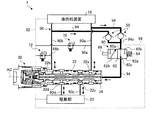
まず、図1を用いて、実施形態の電動油圧回路1の構成について説明する。図1は、実施形態の電動油圧回路を示す模式図である。電動油圧回路1は、油供給装置10から供給される作動油の油圧によって駆動部20を駆動する。油供給装置10と駆動部20との間は、切替弁30を介して、供給油路90及び補助供給油路92によって接続される。供給油路90は、第1供給油路90aと、第2供給油路90bと、第3供給油路90cと、第4供給油路90dと、を含む。
First, the configuration of the electro-hydraulic circuit 1 of the embodiment will be described with reference to FIG. FIG. 1 is a schematic diagram showing an electro-hydraulic circuit according to an embodiment. The electrohydraulic circuit 1 drives the
第1供給油路90aは、油供給装置10と切替弁30とを接続する。第1供給油路90aは、パイロット油圧路94に分岐する。第1供給油路90aは、さらに、第1開放油路96aに分岐する。第1開放油路96aは、第1開放弁70を介して補助供給油路92に接続する。第1開放弁70は、第1供給油路90aの油圧が所定の値を超えた場合に開放されて、作動油を補助供給油路92に排出する。
The first
第2供給油路90bは、油供給装置10と切替弁30とを接続する。第2供給油路90bは、パイロット油圧路94に分岐する。第2供給油路90bは、さらに、第2開放油路96bに分岐する。第2開放油路96bは、第2開放弁72を介して補助供給油路92に接続する。第2開放弁72は、第2供給油路90bの油圧が所定の値を超えた場合に開放されて、作動油を補助供給油路92に排出する。
The second
第3供給油路90cは、切替弁30と駆動部20とを接続する。第4供給油路90dは、切替弁30と駆動部20とを接続する。
The third
補助供給油路92は、切替弁30において、後述する第1付勢手段36(図2参照)が設けられる内部空間36aを通過する。補助供給油路92は、第3供給油路90c及び第4供給油路90dに接続してもよい。この場合、補助供給油路92から第3供給油路90c及び第4供給油路90dへの作動油の流通を許容する。また、第3供給油路90c及び第4供給油路90dから補助供給油路92への作動油の流通を遮断する。
The auxiliary
パイロット油圧路94は、逆止弁50及び電磁弁60を介して、切替弁30に接続される。パイロット油圧路94は、実施形態において、第1供給油路90a及び第2供給油路90bから分岐し、合流部94aにおいて合流して、切替弁30に接続される。
The pilot
油供給装置10は、第1供給油路90a、第2供給油路90b及び補助供給油路92に作動油を供給する。油供給装置10は、例えば、電動モータと、電動モータの回転に応じて作動油を2経路(第1供給油路90a及び第2供給油路90b)に吐出可能な可変容積型の油圧ポンプと、を含む。油供給装置10は、例えば、供給油路90を流通する作動油の流量が不足した場合に、補助供給油路92を介して供給油路90に作動油を供給するアキュムレータを含む。
The
駆動部20は、第3供給油路90c及び第4供給油路90dから作動油が供給されることによって駆動する。駆動部20は、例えば、航空機の動翼の舵面を動作させるアクチュエータが適用される。アクチュエータは、シリンダと、シリンダの内部に設けられるピストンと、ピストンに連結されたロッドと、を含む。アクチュエータは、シリンダ及びピストンによって、第3供給油路90cに接続する第1油室と、第4供給油路90dに接続する第2油室と、を形成する。ロッドは、舵面に接続される。舵面は、アクチュエータによって搖動可能に構成される。
The
駆動部20は、複数の作動モードを含む。作動モードは、実施形態において、ノーマルモードと、ダンピングモードと、を含む。駆動部20は、ノーマルモードにおいて、供給油路90を介して油供給装置10から作動油が供給されることによって駆動する。駆動部20は、ダンピングモードにおいて、供給油路90を介する油供給装置10からの作動油の供給が遮断される。この際、補助供給油路92を介して第3供給油路90c及び第4供給油路90dに作動油が供給される。すなわち、アクチュエータは、ダンピングモードにおいて、第1油室と第2油室とが、第3供給油路90c、切替弁30及び第4供給油路90dを介して連通する。この際、舵面による空気負荷等の外力によって第1油室と第2油室との間を作動油が移動するとともに、必要に応じて補助供給油路92を介して第3供給油路90c及び第4供給油路90dに作動油が供給される。
The
切替弁30は、供給油路90に設けられる。切替弁30は、駆動部20に供給される作動油の複数の切替油路を切り替える。切替弁30は、パイロット油圧路94から供給される作動油のパイロット油圧によって、複数の切替油路を切り替える。切替弁30の切替油路は、実施形態において、第1切替油路と、第2切替油路と、を含む。第1切替油路は、油供給装置10と駆動部20とを接続する供給油路90を連通させる。すなわち、第1切替油路は、第1供給油路90aと第3供給油路90cとを連通させる。第1切替油路は、第2供給油路90bと第4供給油路90dとを連通させる。第2切替油路は、第1供給油路90aと第3供給油路90cとを遮断させる。第2切替油路は、第2供給油路90bと第4供給油路90dとを遮断させる。第2切替油路は、第3供給油路90cと第4供給油路90dとを後述する絞り要素30b(図2参照)を介して連通させる。
The switching
逆止弁50は、パイロット油圧路94に設けられる。逆止弁50は、実施形態において、第1供給油路90aと合流部94aとの間に設けられる。逆止弁50は、第1供給油路90aから電磁弁60への作動油の流通を許容する。逆止弁50は、電磁弁60から第1供給油路90aへの作動油の流通を遮断する。逆止弁50は、実施形態において、第2供給油路90bと合流部94aとの間に設けられる。逆止弁50は、第2供給油路90bから電磁弁60への作動油の流通を許容する。逆止弁50は、電磁弁60から第2供給油路90bへの作動油の流通を遮断する。
The
電磁弁60は、パイロット油圧となる作動油の流通方向において、2つの逆止弁50よりも下流側のパイロット油圧路94に設けられる。電磁弁60は、切替弁30への作動油の供給状態を切り替える。電磁弁60は、弁体62と、付勢手段64と、電磁駆動部66と、を含む。
The
弁体62は、供給ポート60a及び排出ポート60bのうちいずれか一方を選択的に切替弁側ポート60cに接続する。供給ポート60aは、パイロット油圧路94を介して逆止弁50に連通する。排出ポート60bは、排出油路98に連通する。排出油路98は、補助供給油路92等に連通する。切替弁側ポート60cは、パイロット油圧路94を介して切替弁30に連通する。
The
弁体62は、供給ポート60aと切替弁側ポート60cとを接続させる供給位置62aと、排出ポート60bと切替弁側ポート60cとを接続させる排出位置62bと、の間を移動する。付勢手段64は、弁体62を供給位置62aに付勢する。付勢手段64は、実施形態において、圧縮バネである。電磁駆動部66は、例えば、外部の制御装置から通電可能に構成される。電磁駆動部66は、通電時において、付勢手段64の付勢力に抗して、弁体62を排出位置62bに移動させる。弁体62が供給位置62aにある場合、切替弁30にパイロット油圧となる作動油が供給される。弁体62が排出位置62bにある場合、排出ポート60bから作動油が排出可能となる。
The
次に、図2を用いて、切替弁30の詳細な構成について説明する。図2は、実施形態の切替弁を示す模式図である。切替弁30は、スリーブ32と、スプール34と、第1付勢手段36と、封止材38と、第3開放弁40と、を備える。
Next, a detailed configuration of the switching
スリーブ32は、切替弁30の外形となる筒形状である。スリーブ32には、複数のポートが設けられる。スリーブ32は、第1供給側ポート32aと、第2供給側ポート32bと、第1駆動部側ポート32cと、第2駆動部側ポート32dと、を有する。第1供給側ポート32aは、第1供給油路90aを介して油供給装置10に連通する。第2供給側ポート32bは、第2供給油路90bを介して油供給装置10に連通する。第1駆動部側ポート32cは、第3供給油路90cを介して駆動部20に連通する。第2駆動部側ポート32dは、第4供給油路90dを介して駆動部20に連通する。複数のポートを接続することによって、作動油の流路30aが形成される。流路30aは、複数の切替油路を含む。
The
スプール34は、複数の凹部を有する棒形状である。凹部は、切替弁30における作動油の流路30aである。スプール34は、スリーブ32の内部に設けられる。スプール34は、スリーブ32の内部において、軸方向ADに移動可能である。スプール34の一方の端部34aは、パイロット油圧路94に連通する。スプール34は、パイロット油圧路94を流通する作動油のパイロット油圧によって、他方の端部34b側に付勢される。
The
第1付勢手段36は、スプール34の端部34b側に設けられる。第1付勢手段36は、切替弁30の内部空間36aに設けられる。内部空間36aは、補助供給油路92が通過する。第1付勢手段36は、パイロット油圧に抗してスプール34を端部34a側に付勢する。第1付勢手段36は、実施形態において、圧縮バネである。
The first urging means 36 is provided on the
切替弁30は、スプール34がスリーブ32の内部において軸方向DAに移動することによって、作動油の切替油路を切り替える。パイロット油圧が第1付勢手段36の付勢力に抗してスプール34を端部34b側に移動させる場合、第1供給側ポート32aと第1駆動部側ポート32cとが連通し、第2供給側ポート32bと第2駆動部側ポート32dとが連通する。すなわち、第1供給油路90aと第3供給油路90cとを連通させ、第2供給油路90bと第4供給油路90dとを連通させる第1切替油路が開放される。第1付勢手段36の付勢力がパイロット油圧に抗してスプール34を端部34a側に移動させる場合、第1供給側ポート32a及び第2供給側ポート32bが閉塞し、第1駆動部側ポート32cと第2駆動部側ポート32dとが連通する。すなわち、第1供給油路90aと第3供給油路90cとを遮断させ、第2供給油路90bと第4供給油路90dとを遮断させ、第3供給油路90cと第4供給油路90dとを連通させる第2切替油路が開放される。実施形態において、第2切替油路において連通する第1駆動部側ポート32cと第2駆動部側ポート32dとの間の流路30aには、絞り要素30bが設けられる。
The switching
封止材38は、切替弁30に設けられる。封止材38は、パイロット油圧となる作動油を封止する。封止材38は、実施形態において、スリーブ32と、スプール34との間に設けられる。封止材38は、切替弁30内部の流路30aを、パイロット油圧路94から封止する。すなわち、封止材38は、切替弁30の切替油路をパイロット油圧路94から封止する。封止材38は、流路30aを流通する作動油と、パイロット油圧となる作動油とが、互いに漏出しないように設けられる。封止材38は、スプール34の端部34a側近傍に設けられることが好ましい。
The sealing
スプール34は、細孔34cと、逃がし孔34dと、を有する。細孔34cは、端部34a側の中心から端部34b側に向かって、スプール34の軸方向ADに沿って形成される。細孔34cは、端部34aにおいて、パイロット油圧路94に連通する。逃がし孔34dは、端部34b側の中心から端部34a側に向かって、スプール34の軸方向ADに沿って形成される。逃がし孔34dは細孔34cに連通する。逃がし孔34dの径は、細孔34cの径より小さい。逃がし孔34dは、パイロット油圧路94及び細孔34cを流通するパイロット油圧となる作動油を、スプール34の外部に排出する。逃がし孔34dは、実施形態において、切替弁30の内部空間36aを介して、補助供給油路92に作動油を排出する。
The
第3開放弁40は、流通方向において、2つの逆止弁50よりも下流側のパイロット油圧路94に設けられる。第3開放弁40は、パイロット油圧路94のパイロット油圧が所定の値を超えた場合、パイロット油圧路94から作動油を排出して、パイロット油圧を開放する。
The third
第3開放弁40は、実施形態において、第1付勢手段36の内側に設けられる。第3開放弁40は、弁体42と、第2付勢手段44と、を含む。弁体42は、スプール34の端部34b側に設けられる。弁体42は、逃がし孔34dを閉塞する。弁体42は、スプール34の逃がし孔34dとメタルタッチする。第2付勢手段44は、弁体42に対して、スプール34の端部34b側とは反対側に設けられる。第2付勢手段44は、弁体42をスプール34の逃がし孔34dに付勢する。第2付勢手段44は、実施形態において、圧縮バネである。弁体42及び第2付勢手段44の移動方向は、実施形態において、軸方向ADと同じ方向である。
The
次に、切替弁30の動作について説明する。逃がし孔34dにおけるパイロット油圧が所定の値以下の場合、弁体42は、パイロット油圧に抗して逃がし孔34dを閉塞する。逃がし孔34dにおけるパイロット油圧が所定の値を超えた場合、弁体42は、第2付勢手段44の付勢力に抗して逃がし孔34dを開放する。弁体42が逃がし孔34dを開放することによって、パイロット油圧路94、細孔34c及び逃がし孔34dを流通するパイロット油圧となる作動油は、切替弁30の内部空間36aを介して、補助供給油路92に排出される。
Next, the operation of the switching
次に、電動油圧回路1の作動について説明する。電動油圧回路1は、電磁弁60における作動油の供給状態を切り替えることによって、駆動部20の作動モードを切り替えることが可能である。電磁弁60における作動油の供給状態は、弁体62を供給位置62a又は排出位置62bに移動させることによって切り替えることができる。
Next, the operation of the electro-hydraulic circuit 1 will be described. The electro-hydraulic circuit 1 can switch the operation mode of the
電磁弁60の弁体62が供給位置62aにある場合、作動油は、第1供給油路90aからパイロット油圧路94に導入され、逆止弁50、電磁弁60の供給ポート60a及び切替弁側ポート60cを介して、切替弁30側に供給される。これにより、パイロット油圧路94内部の作動油は、パイロット油圧が上昇する。パイロット油圧路94内部の作動油のパイロット油圧が上昇すると、作動油は、切替弁30のスプール34を端部34b側に付勢する。作動油のパイロット油圧が第1付勢手段36の付勢力に抗してスプール34を端部34b側に移動させると、切替弁30は、第1切替油路が開放される。第1切替油路は、第1供給油路90aと第3供給油路90cとが連通し、第2供給油路90bと第4供給油路90dとが連通する。したがって、油供給装置10から供給油路90に供給された作動油は、切替弁30を介して駆動部20に供給される。これにより、駆動部20は、ノーマルモードによって駆動する。
When the
電磁弁60の弁体62が排出位置62bにある場合、パイロット油圧路94における電磁弁60と切替弁30との間に流通する作動油は、パイロット油圧路94から、切替弁側ポート60c及び排出ポート60bを介して、排出油路98に排出される。これにより、パイロット油圧路94内部の作動油は、パイロット油圧が低下する。パイロット油圧路94内部の作動油のパイロット油圧が低下すると、作動油が切替弁30のスプール34を端部34b側に付勢する付勢力が低下する。第1付勢手段36が作動油のパイロット油圧の付勢力に抗してスプール34を端部34a側に移動させると、切替弁30は、第2切替油路が開放される。第2切替油路は、第1供給油路90aと第3供給油路90cとが遮断し、第2供給油路90bと第4供給油路90dとが遮断する。また、第2切替油路は、第3供給油路90cと第4供給油路90dとが絞り要素30bを介して連通する。これにより、駆動部20は、ダンピングモードとなる。
When the
以上のように、実施形態の切替弁30によれば、逃がし孔34d及び弁体42によってパイロット油圧が過加圧となることを抑制することができる。また、切替弁30は、パイロット油圧を排出する逃がし孔34d、弁体42及び第2付勢手段44をスプール34に設けるので、パイロット油圧路94から分岐して開放弁が設けられる油路を追加させる構成に比べて、軽量化することができる。
As described above, according to the switching
また、実施形態の切替弁30は、弁体42及び第2付勢手段44の移動方向が、軸方向ADと同じ方向であることによって、第2付勢手段44の付勢力がパイロット油圧に対して効率的に抗することができる。これにより、切替弁30は、第2付勢手段44の付勢力を小さくすることができる。
Further, in the switching
また、実施形態の切替弁30は、第2付勢手段44が、圧縮バネであることによって、弁体42及び第2付勢手段44の構成をより簡略化することができる。
Further, in the switching
また、実施形態の切替弁30は、弁体42が、スプール34の逃がし孔34dとメタルタッチすることによって、より好適に、弁体42によって逃がし孔34dを閉塞することができる。これにより、切替弁30は、パイロット油圧が所定の値以下である場合の作動油の漏洩を抑制することができる。
Further, in the switching
また、実施形態の切替弁30は、スリーブ32とスプール34との間に設けられ、切替油路(流路30a)をパイロット油圧となる作動油を供給するパイロット油圧路94から封止する封止材38を備える。これにより、切替弁30は、より好適に、スリーブ32及びスプール34を密封することができる。これにより、切替弁30は、パイロット油圧の漏洩を抑制することができる。
Further, the switching
また、実施形態の電動油圧回路1は、作動油を供給する油供給装置10と、油供給装置10から供給される作動油の油圧によって駆動する駆動部20と、の間を接続する供給油路90と、供給油路90に設けられ、パイロット油圧によって駆動部20へ供給される作動油の複数の切替油路を切り替える切替弁30と、切替弁30に接続され、パイロット油圧となる作動油を供給するパイロット油圧路94と、パイロット油圧路94に設けられる逆止弁50と、作動油の流通方向において、逆止弁50よりも下流側のパイロット油圧路94に設けられ、切替弁30への作動油の供給状態を切り替える電磁弁60と、切替弁30に設けられ、パイロット油圧となる作動油を封止する封止材38と、を備える。電動油圧回路1は、逆止弁50及び封止材38によってパイロット油圧の漏洩を抑制することによって、供給油路90の圧力低下により不意に切替油路が切り替わることを抑制することができる。また、電動油圧回路1は、逃がし孔34d及び弁体42によってパイロット油圧が過加圧となることを抑制することによって、電動油圧回路1の破損を抑制することができる。また、電動油圧回路1は、パイロット油圧を排出する逃がし孔34d、弁体42及び第2付勢手段44をスプール34に設けるので、パイロット油圧路94から分岐して開放弁が設けられる油路を追加させる構成に比べて、軽量化することができる。電動油圧回路1は、切替弁30の切り替えにパイロット油圧を用い、パイロット油圧の供給を電磁弁60によって制御するので、切替弁30の切り替えに直接電磁弁を用いるよりも電磁弁60を小さくできる。したがって、電動油圧回路1は、電動油圧回路1全体を軽量化し、消費電力を抑制することができる。
Further, the electrohydraulic circuit 1 of the embodiment is a supply oil passage connecting between an
また、舵面を有する動翼と、実施形態の電動油圧回路1を用いて、舵面を動作させる駆動部20としてのアクチュエータと、を備える航空機は、電動油圧回路1の逆止弁50及び封止材38によってパイロット油圧の漏洩を抑制する。これにより、航空機は、電動油圧回路1の供給油路90の圧力低下により不意に切替油路が切り替わることを抑制することができる。また、航空機は、電動油圧回路1の逃がし孔34d及び弁体42によってパイロット油圧が過加圧となることを抑制することによって、電動油圧回路1の破損を抑制することができる。また、航空機は、電動油圧回路1のパイロット油圧を排出する逃がし孔34d、弁体42及び第2付勢手段44をスプール34に設けるので、パイロット油圧路94から分岐して開放弁が設けられる油路を追加させる構成に比べて、軽量化することができる。航空機は、電動油圧回路1の切替弁30の切り替えにパイロット油圧を用い、パイロット油圧の供給を電磁弁60によって制御するので、切替弁30の切り替えに直接電磁弁を用いるよりも電磁弁60を小さくできる。したがって、航空機は、電動油圧回路1全体を軽量化し、消費電力を抑制することができる。
Further, an aircraft provided with a moving blade having a control surface and an actuator as a
1 電動油圧回路
10 油供給装置
20 駆動部
30 切替弁
30a 流路
30b 絞り要素
32 スリーブ
32a 第1供給側ポート
32b 第2供給側ポート
32c 第1駆動部側ポート
32d 第2駆動部側ポート
34 スプール
34a、34b 端部
34c 細孔
34d 逃がし孔
36 第1付勢手段
36a 内部空間
38 封止材
40 第3開放弁
42 弁体
44 第2付勢手段
50 逆止弁
60 電磁弁
60a 供給ポート
60b 排出ポート
60c 切替弁側ポート
62 弁体
62a 供給位置
62b 排出位置
64 付勢手段
66 電磁駆動部
70 第1開放弁
72 第2開放弁
90 供給油路
90a 第1供給油路
90b 第2供給油路
90c 第3供給油路
90d 第4供給油路
92 補助供給油路
94 パイロット油圧路
94a 合流部
96a 第1開放油路
96b 第2開放油路
98 排出油路
AD 軸方向
1 Electro-
Claims (7)
前記スリーブの内部に設けられて、パイロット油圧によって軸方向に移動して、前記複数のポートを接続することで形成される作動油の流路である切替油路を切り替えるスプールと、
前記パイロット油圧に抗して前記スプールを付勢する第1付勢手段と、
前記スプールに設けられて、前記パイロット油圧となる作動油を排出する逃がし孔と、
前記逃がし孔を閉塞する弁体と、
前記パイロット油圧に抗して前記弁体を前記スプールの前記逃がし孔に付勢すると共に、前記パイロット油圧が所定の値を超えた場合に前記逃がし孔を開放する第2付勢手段と、を備えることを特徴とする切替弁。 A sleeve with multiple ports and
A spool provided inside the sleeve and moving in the axial direction by pilot hydraulic pressure to switch a switching oil passage which is a flow path of hydraulic oil formed by connecting the plurality of ports.
The first urging means for urging the spool against the pilot hydraulic pressure,
A relief hole provided in the spool to discharge the hydraulic oil serving as the pilot hydraulic pressure,
A valve body that closes the relief hole and
It is provided with a second urging means for urging the valve body to the relief hole of the spool against the pilot hydraulic pressure and opening the relief hole when the pilot hydraulic pressure exceeds a predetermined value. A switching valve characterized by that.
前記供給油路に設けられ、前記パイロット油圧によって前記駆動部へ供給される前記作動油の複数の切替油路を切り替える請求項1から4のいずれか1項に記載の切替弁と、
前記切替弁に接続され、前記パイロット油圧となる作動油を供給するパイロット油圧路と、
前記パイロット油圧路に設けられる逆止弁と、
前記作動油の流通方向において、前記逆止弁よりも下流側の前記パイロット油圧路に設けられ、前記切替弁への前記作動油の供給状態を切り替える電磁弁と、
前記切替弁に設けられ、前記パイロット油圧となる前記作動油を封止する封止材と、を備えることを特徴とする電動油圧回路。 A supply oil passage connecting between an oil supply device for supplying hydraulic oil and a drive unit driven by the hydraulic pressure of the hydraulic oil supplied from the oil supply device.
The switching valve according to any one of claims 1 to 4, which is provided in the supply oil passage and switches a plurality of switching oil passages for the hydraulic oil supplied to the drive unit by the pilot hydraulic pressure.
A pilot hydraulic path connected to the switching valve and supplying hydraulic oil to be the pilot hydraulic pressure,
The check valve provided in the pilot hydraulic path and
A solenoid valve provided in the pilot hydraulic passage on the downstream side of the check valve in the flow direction of the hydraulic oil to switch the supply state of the hydraulic oil to the switching valve.
An electro-hydraulic circuit provided on the switching valve and comprising a sealing material for sealing the hydraulic oil that serves as the pilot hydraulic pressure.
請求項6に記載の電動油圧回路を用いて、前記舵面を動作させる前記駆動部としてのアクチュエータと、を備えることを特徴とする航空機。 A moving blade with a control surface and
An aircraft comprising the actuator as a driving unit for operating the control surface by using the electro-hydraulic circuit according to claim 6.
Priority Applications (4)
| Application Number | Priority Date | Filing Date | Title |
|---|---|---|---|
| JP2020009472A JP6977072B2 (en) | 2020-01-23 | 2020-01-23 | Switching valve, electro-hydraulic circuit and aircraft |
| EP20915467.3A EP4079633A4 (en) | 2020-01-23 | 2020-12-17 | Selector valve, electro-hydraulic circuit and aircraft |
| PCT/JP2020/047103 WO2021149416A1 (en) | 2020-01-23 | 2020-12-17 | Selector valve, electro-hydraulic circuit and aircraft |
| US17/794,833 US20230086713A1 (en) | 2020-01-23 | 2020-12-17 | Switching valve, electro-hydrostatic circuit, and aircraft |
Applications Claiming Priority (1)
| Application Number | Priority Date | Filing Date | Title |
|---|---|---|---|
| JP2020009472A JP6977072B2 (en) | 2020-01-23 | 2020-01-23 | Switching valve, electro-hydraulic circuit and aircraft |
Publications (2)
| Publication Number | Publication Date |
|---|---|
| JP2021116840A JP2021116840A (en) | 2021-08-10 |
| JP6977072B2 true JP6977072B2 (en) | 2021-12-08 |
Family
ID=76992190
Family Applications (1)
| Application Number | Title | Priority Date | Filing Date |
|---|---|---|---|
| JP2020009472A Active JP6977072B2 (en) | 2020-01-23 | 2020-01-23 | Switching valve, electro-hydraulic circuit and aircraft |
Country Status (4)
| Country | Link |
|---|---|
| US (1) | US20230086713A1 (en) |
| EP (1) | EP4079633A4 (en) |
| JP (1) | JP6977072B2 (en) |
| WO (1) | WO2021149416A1 (en) |
Family Cites Families (8)
| Publication number | Priority date | Publication date | Assignee | Title |
|---|---|---|---|---|
| US3628424A (en) * | 1970-05-14 | 1971-12-21 | Gen Signal Corp | Hydraulic power circuits employing remotely controlled directional control valves |
| JP2004100727A (en) * | 2002-09-05 | 2004-04-02 | Ts Corporation | Control circuit of servo actuator |
| JP4515433B2 (en) | 2006-10-12 | 2010-07-28 | ナブテスコ株式会社 | Actuation system |
| CN108350911B (en) * | 2015-10-02 | 2023-11-21 | 阿斯科公司 | Assembly of a manifold module, a valve housing and a slide valve assembly for a manifold group |
| DE102015221940B3 (en) * | 2015-11-09 | 2016-10-20 | Festo Ag & Co. Kg | valve assembly |
| JP2019007515A (en) * | 2017-06-22 | 2019-01-17 | 日立オートモティブシステムズ株式会社 | Hydraulic control valve |
| DE102017012102A1 (en) * | 2017-12-21 | 2019-06-27 | Hydac Fluidtechnik Gmbh | Device and valve for flow force compensation |
| JP7033463B2 (en) * | 2018-02-21 | 2022-03-10 | 川崎重工業株式会社 | Spool valve device |
-
2020
- 2020-01-23 JP JP2020009472A patent/JP6977072B2/en active Active
- 2020-12-17 US US17/794,833 patent/US20230086713A1/en active Pending
- 2020-12-17 EP EP20915467.3A patent/EP4079633A4/en active Pending
- 2020-12-17 WO PCT/JP2020/047103 patent/WO2021149416A1/en unknown
Also Published As
| Publication number | Publication date |
|---|---|
| EP4079633A1 (en) | 2022-10-26 |
| JP2021116840A (en) | 2021-08-10 |
| WO2021149416A1 (en) | 2021-07-29 |
| US20230086713A1 (en) | 2023-03-23 |
| EP4079633A4 (en) | 2023-06-07 |
Similar Documents
| Publication | Publication Date | Title |
|---|---|---|
| JP4515433B2 (en) | Actuation system | |
| JP5389461B2 (en) | Hydraulic motor | |
| JP6182447B2 (en) | Fluid pressure control device | |
| KR100475517B1 (en) | Hydraulic drive device of working machine | |
| JP3508955B2 (en) | Hydraulic motor drive | |
| JP6788395B2 (en) | Cylinder drive | |
| US8833391B2 (en) | Valve arrangement | |
| JP6977072B2 (en) | Switching valve, electro-hydraulic circuit and aircraft | |
| JP7297617B2 (en) | Electro-hydraulic actuator system, hydraulic circuit for electro-hydraulic actuator system, and steam turbine system including the same | |
| KR970003503B1 (en) | Brake valve | |
| JP7027469B2 (en) | Electro-hydraulic circuits and aircraft | |
| JP5514082B2 (en) | Hydraulic drive system for deck crane | |
| JP2011503478A (en) | Hydraulic valve device | |
| JP7201463B2 (en) | construction machinery | |
| JP4836350B2 (en) | Hydraulic control device | |
| JP2020197231A (en) | Fluid pressure device | |
| JP2019219003A (en) | Fluid pressure control device | |
| CN112739914B (en) | Double acting hydraulic actuator with different pumps for each actuation direction | |
| JP7411417B2 (en) | Hydraulic circuits, directional valves for hydraulic circuits and construction machinery | |
| WO2023106179A1 (en) | Fluid pressure circuit | |
| WO2023176686A1 (en) | Fluid pressure control device | |
| WO2023162884A1 (en) | Fluid pressure circuit | |
| JP5470180B2 (en) | Control valve | |
| US20190376534A1 (en) | Electromagnetic pressure reducing valve and fluid pressure control device including electromagnetic pressure reducing valve | |
| JP3892455B2 (en) | Actuation system |
Legal Events
| Date | Code | Title | Description |
|---|---|---|---|
| A621 | Written request for application examination |
Free format text: JAPANESE INTERMEDIATE CODE: A621 Effective date: 20201125 |
|
| TRDD | Decision of grant or rejection written | ||
| A01 | Written decision to grant a patent or to grant a registration (utility model) |
Free format text: JAPANESE INTERMEDIATE CODE: A01 Effective date: 20211012 |
|
| A61 | First payment of annual fees (during grant procedure) |
Free format text: JAPANESE INTERMEDIATE CODE: A61 Effective date: 20211110 |
|
| R150 | Certificate of patent or registration of utility model |
Ref document number: 6977072 Country of ref document: JP Free format text: JAPANESE INTERMEDIATE CODE: R150 |