JP5227545B2 - Sprocket wheel cover device for manually operated chainsaw - Google Patents
Sprocket wheel cover device for manually operated chainsaw Download PDFInfo
- Publication number
- JP5227545B2 JP5227545B2 JP2007183414A JP2007183414A JP5227545B2 JP 5227545 B2 JP5227545 B2 JP 5227545B2 JP 2007183414 A JP2007183414 A JP 2007183414A JP 2007183414 A JP2007183414 A JP 2007183414A JP 5227545 B2 JP5227545 B2 JP 5227545B2
- Authority
- JP
- Japan
- Prior art keywords
- sprocket wheel
- wheel cover
- nut
- stud bolt
- play
- Prior art date
- Legal status (The legal status is an assumption and is not a legal conclusion. Google has not performed a legal analysis and makes no representation as to the accuracy of the status listed.)
- Active
Links
- 238000005520 cutting process Methods 0.000 description 11
- 238000000034 method Methods 0.000 description 8
- 238000003780 insertion Methods 0.000 description 6
- 230000037431 insertion Effects 0.000 description 6
- 229910052751 metal Inorganic materials 0.000 description 5
- 239000002184 metal Substances 0.000 description 5
- 239000004033 plastic Substances 0.000 description 4
- 238000002485 combustion reaction Methods 0.000 description 3
- 229910000831 Steel Inorganic materials 0.000 description 2
- 238000011161 development Methods 0.000 description 2
- 239000000463 material Substances 0.000 description 2
- 239000010959 steel Substances 0.000 description 2
- FYYHWMGAXLPEAU-UHFFFAOYSA-N Magnesium Chemical compound [Mg] FYYHWMGAXLPEAU-UHFFFAOYSA-N 0.000 description 1
- 229910052782 aluminium Inorganic materials 0.000 description 1
- XAGFODPZIPBFFR-UHFFFAOYSA-N aluminium Chemical compound [Al] XAGFODPZIPBFFR-UHFFFAOYSA-N 0.000 description 1
- 238000005266 casting Methods 0.000 description 1
- 238000010586 diagram Methods 0.000 description 1
- 238000006073 displacement reaction Methods 0.000 description 1
- 238000007688 edging Methods 0.000 description 1
- 238000005516 engineering process Methods 0.000 description 1
- 238000011900 installation process Methods 0.000 description 1
- 230000003993 interaction Effects 0.000 description 1
- 229910052749 magnesium Inorganic materials 0.000 description 1
- 239000011777 magnesium Substances 0.000 description 1
- 238000012423 maintenance Methods 0.000 description 1
- 239000002991 molded plastic Substances 0.000 description 1
- 238000007781 pre-processing Methods 0.000 description 1
- 238000002360 preparation method Methods 0.000 description 1
- 238000003825 pressing Methods 0.000 description 1
Images


Classifications
-
- B—PERFORMING OPERATIONS; TRANSPORTING
- B27—WORKING OR PRESERVING WOOD OR SIMILAR MATERIAL; NAILING OR STAPLING MACHINES IN GENERAL
- B27B—SAWS FOR WOOD OR SIMILAR MATERIAL; COMPONENTS OR ACCESSORIES THEREFOR
- B27B17/00—Chain saws; Equipment therefor
- B27B17/02—Chain saws equipped with guide bar
-
- F—MECHANICAL ENGINEERING; LIGHTING; HEATING; WEAPONS; BLASTING
- F16—ENGINEERING ELEMENTS AND UNITS; GENERAL MEASURES FOR PRODUCING AND MAINTAINING EFFECTIVE FUNCTIONING OF MACHINES OR INSTALLATIONS; THERMAL INSULATION IN GENERAL
- F16B—DEVICES FOR FASTENING OR SECURING CONSTRUCTIONAL ELEMENTS OR MACHINE PARTS TOGETHER, e.g. NAILS, BOLTS, CIRCLIPS, CLAMPS, CLIPS OR WEDGES; JOINTS OR JOINTING
- F16B37/00—Nuts or like thread-engaging members
- F16B37/04—Devices for fastening nuts to surfaces, e.g. sheets, plates
- F16B37/041—Releasable devices
- F16B37/043—Releasable devices with snap action
-
- F—MECHANICAL ENGINEERING; LIGHTING; HEATING; WEAPONS; BLASTING
- F16—ENGINEERING ELEMENTS AND UNITS; GENERAL MEASURES FOR PRODUCING AND MAINTAINING EFFECTIVE FUNCTIONING OF MACHINES OR INSTALLATIONS; THERMAL INSULATION IN GENERAL
- F16B—DEVICES FOR FASTENING OR SECURING CONSTRUCTIONAL ELEMENTS OR MACHINE PARTS TOGETHER, e.g. NAILS, BOLTS, CIRCLIPS, CLAMPS, CLIPS OR WEDGES; JOINTS OR JOINTING
- F16B41/00—Measures against loss of bolts, nuts, or pins; Measures against unauthorised operation of bolts, nuts or pins
- F16B41/002—Measures against loss of bolts, nuts or pins
-
- Y—GENERAL TAGGING OF NEW TECHNOLOGICAL DEVELOPMENTS; GENERAL TAGGING OF CROSS-SECTIONAL TECHNOLOGIES SPANNING OVER SEVERAL SECTIONS OF THE IPC; TECHNICAL SUBJECTS COVERED BY FORMER USPC CROSS-REFERENCE ART COLLECTIONS [XRACs] AND DIGESTS
- Y10—TECHNICAL SUBJECTS COVERED BY FORMER USPC
- Y10S—TECHNICAL SUBJECTS COVERED BY FORMER USPC CROSS-REFERENCE ART COLLECTIONS [XRACs] AND DIGESTS
- Y10S411/00—Expanded, threaded, driven, headed, tool-deformed, or locked-threaded fastener
- Y10S411/999—Expanded, threaded, driven, headed, tool-deformed, or locked-threaded fastener with retainer, e.g. tether
-
- Y—GENERAL TAGGING OF NEW TECHNOLOGICAL DEVELOPMENTS; GENERAL TAGGING OF CROSS-SECTIONAL TECHNOLOGIES SPANNING OVER SEVERAL SECTIONS OF THE IPC; TECHNICAL SUBJECTS COVERED BY FORMER USPC CROSS-REFERENCE ART COLLECTIONS [XRACs] AND DIGESTS
- Y10—TECHNICAL SUBJECTS COVERED BY FORMER USPC
- Y10T—TECHNICAL SUBJECTS COVERED BY FORMER US CLASSIFICATION
- Y10T74/00—Machine element or mechanism
- Y10T74/21—Elements
- Y10T74/2186—Gear casings
Landscapes
- Engineering & Computer Science (AREA)
- General Engineering & Computer Science (AREA)
- Mechanical Engineering (AREA)
- Life Sciences & Earth Sciences (AREA)
- Wood Science & Technology (AREA)
- Forests & Forestry (AREA)
- Sawing (AREA)
- Connection Of Plates (AREA)
- Devices For Conveying Motion By Means Of Endless Flexible Members (AREA)
Description
本発明は、手で操縦されるチェーンソーのスプロケットホイールカバー装置であって、スプロケットホイールカバーと、ケーシングと、該ケーシングに固定され、スプロケットホイールカバーをケーシングと螺合させるための少なくとも1つのスタッドボルトと、組み立て状態でスプロケットホイールカバーの開口部を貫通して案内されるスタッドボルトのねじ自由端に螺合するナットとを有する前記スプロケットホイールカバー装置に関するものである。 The present invention is a manually operated chain saw sprocket wheel cover device comprising a sprocket wheel cover, a casing, and at least one stud bolt fixed to the casing for screwing the sprocket wheel cover into the casing. Further, the present invention relates to the sprocket wheel cover device having a nut screwed to a screw free end of a stud bolt guided through the opening of the sprocket wheel cover in an assembled state.
手で操縦されるチェーンソーは、ガイドレールの外面を周回する切断チェーンを有している。切断チェーンを駆動するため、駆動原動機により駆動される、外歯を持つスプロケットホイールが設けられている。スプロケットホイールの外面の歯は切断チェーンの鎖環の間に係合し、切断チェーンを駆動する。 A manually operated chain saw has a cutting chain that goes around the outer surface of the guide rail. In order to drive the cutting chain, a sprocket wheel with external teeth driven by a drive prime mover is provided. The teeth on the outer surface of the sprocket wheel engage between the chain rings of the cutting chain and drive the cutting chain.
スプロケットホイールの駆動軸はチェーンソーのケーシング内で支持されている。ケーシングには、スプロケットホイールの領域を覆うスプロケットホイールカバーがねじ止めされている。ねじ止めのため、少なくとも1つのスタッドボルトがケーシングに固定され、スタッドボルトは組み立て状態でスプロケットホイールカバーを貫通するように案内されている。スタッドボルトのねじ自由端には、スプロケットホイールカバーをケーシングに対し押圧させるナットを螺合させる。 The drive shaft of the sprocket wheel is supported in the casing of the chainsaw. The casing is screwed with a sprocket wheel cover that covers the region of the sprocket wheel. For screwing, at least one stud bolt is fixed to the casing, and the stud bolt is guided through the sprocket wheel cover in the assembled state. A nut that presses the sprocket wheel cover against the casing is screwed onto the screw free end of the stud bolt.
切断チェーンのガイドレールは少なくとも1つのスタッドボルトを挿通することでケーシングとスプロケットホイールカバーとの間に締め付け保持される。すなわちスプロケットホイールカバーは保護機能以外に、ガイドレールを保持する保持機能をも有している。ガイドレールの保守作業のため、或いは、ガイドレールを交換するためにスプロケットホイールカバーを取り外せば、ガイドレールの取り外し或いは交換を行なうことができる。組み立ての際には、まず少なくとも1つのスタッドボルトをガイドレールに挿通し、次に少なくとも1つのスタッドボルトをスプロケットホイールカバーに設けた開口部に貫通させるようにしてスプロケットホイールカバーを取り付ける。組み立てを終了するため、ナットをスタッドボルトのねじ自由端に取り付けて回転させ、引き締める。 The guide rail of the cutting chain is clamped and held between the casing and the sprocket wheel cover by inserting at least one stud bolt. That is, the sprocket wheel cover has a holding function for holding the guide rail in addition to the protection function. If the sprocket wheel cover is removed for maintenance work of the guide rail or for exchanging the guide rail, the guide rail can be removed or replaced. When assembling, first, at least one stud bolt is inserted into the guide rail, and then at least one stud bolt is passed through the opening provided in the sprocket wheel cover, and the sprocket wheel cover is attached. To finish the assembly, attach the nut to the screw free end of the stud bolt, rotate and tighten.
特に作業場所で利用者がスプロケットホイールカバーを組み立てることは困難である。ガイドレールとスプロケットホイールカバーとを同時に取り付け位置で保持しなければならず、他方ナットはスタッドボルトに取り付けて回転させる。ナットは抜け落ちて紛失することがある。特に2つのスタッドボルトを設けた構成では、まだ最終的に固定されていないガイドレールのために螺合部が固着することがある。 In particular, it is difficult for the user to assemble the sprocket wheel cover at the work place. The guide rail and sprocket wheel cover must be held simultaneously in the mounting position, while the nut is attached to the stud bolt and rotated. The nut may fall off and be lost. In particular, in the configuration in which two stud bolts are provided, the threaded portion may be fixed due to a guide rail that has not been finally fixed.
本発明の課題は、スプロケットホイールカバーの固定過程が容易であるようにこの種のスプロケットホイールカバー装置を改良することである。 The object of the present invention is to improve a sprocket wheel cover device of this kind so that the fixing process of the sprocket wheel cover is easy.
この課題は、請求項1の構成を備えたスプロケットホイールカバー装置により解決される。 This problem is solved by a sprocket wheel cover device having the configuration of claim 1.
本発明によれば、ナットは紛失不能に、回転可能に、且つ遊びを持ってスプロケットホイールカバーの開口部内で保持されている。前記遊びがスタッドボルトの長手軸線に関し軸線方向の遊び、半径方向の遊び、および/または傾動遊びであるのが有利である。特に、軸線方向の遊びは、少なくとも、ナットへのスタッドボルトの所定のねじ込み深さと同じ大きさである。 According to the present invention, the nut so as not to lose, rotatably, and is held in the opening of the sprocket wheel cover and with play. Advantageously, the play is axial play, radial play and / or tilt play with respect to the longitudinal axis of the stud bolt. In particular, the play in the axial direction is at least as large as the predetermined threading depth of the stud bolt into the nut.
有利には、スタッドボルトの長さとスプロケットホイールカバー内でのナットの前記遊びとは、スプロケットホイールカバーを作動位置に載置したときにナットとスタッドボルトとの螺合を完全に解除でき或いは完全に引き締めることができるように、互いに整合しているのがよい。 Advantageously, the length of the stud bolt and the play of the nut in the sprocket wheel cover is such that when the sprocket wheel cover is placed in the operating position, the screw engagement between the nut and the stud bolt can be completely released. It should be aligned with each other so that it can be tightened.
これにより、スプロケットホイールカバーを少なくとも1つのスタッドボルト上にてスライドさせて取り付けて、ソーチェーンのガイドレールを仮固定することができる。挿通の際、ナットはその遊びのために、スプロケットホイールカバーに固定されるナットにより該スプロケットホイールカバーの挿通が阻害されない程度に撓む。完全に挿通してガイドレールの仮固定が終了した後にはじめてナットを回転させて固定する。このときガイドレールおよびスプロケットホイールカバーの位置固定に特に注意を払う必要はない。逆に取り外す場合には、スプロケットホイールカバーの位置を変更させることなく、ナットをスタッドボルトのねじ端から完全にはずすことができる。螺合部を完全に緩めるまでスプロケットホイールカバー装置の位置は不変である。 As a result, the sprocket wheel cover can be slid onto and mounted on at least one stud bolt, and the guide rail of the saw chain can be temporarily fixed. During insertion, the nut bends to such an extent that play does not hinder the insertion of the sprocket wheel cover by the nut fixed to the sprocket wheel cover. Only after the guide rail is completely fixed and the guide rail is temporarily fixed, the nut is rotated and fixed. At this time, it is not necessary to pay particular attention to fixing the position of the guide rail and the sprocket wheel cover. In the case of removal, the nut can be completely removed from the screw end of the stud bolt without changing the position of the sprocket wheel cover. The position of the sprocket wheel cover device remains unchanged until the threaded portion is completely loosened.
有利な構成では、ナットは雌ねじ部分を有し、該雌ねじ部分にスタッドボルト側で平滑なスリーブ部分が境を接している。スタッドボルトの長さと平滑なスリーブ部分の長さとは、スプロケットホイールカバーを作動位置に載置して該スプロケットホイールカバーの外面に対しナットを完全に引き抜いたときにスタッドボルトが平滑なスリーブ部分に係合するように、互いに整合しているのが合目的である。 In an advantageous configuration, the nut has a female threaded portion, which is bordered by a smooth sleeve portion on the stud bolt side. The length of the stud bolt and the length of the smooth sleeve part are related to the smooth sleeve part when the sprocket wheel cover is placed in the operating position and the nut is completely pulled out from the outer surface of the sprocket wheel cover. The purpose is to be consistent with each other.
スプロケットホイールカバーの取り付け過程の間、スタッドボルトはスリーブ部分内へ変位する。これにより、遊びを持って固定されているナットとスタットボルトとの相互の位置調整が得られる。スタッドボルトのねじ自由端がナットの雌ねじ部分に衝突すると、スタッドボルトのねじ自由端はナットをスプロケットホイールカバーの外面のほうへ押す。前述のように長さの整合が行なわれているので、スタッドボルトは挿通過程の際、特に所定の組み立て位置に達したときに、案内用のスリーブ部分から抜け落ちない。挿通過程はナットのスタッドボルト側に設けた心合わせテーパ部によってさらに補助される。総じて、スプロケットホイールカバーを嵌合させるだけですべての個々の部材相互の正確で確実な相対位置が行なわれる。 During the sprocket wheel cover installation process, the stud bolt is displaced into the sleeve portion. As a result, mutual position adjustment between the nut and the stat bolt fixed with play is obtained. When the free end of the stud bolt collides with the internal thread of the nut, the free end of the stud bolt pushes the nut toward the outer surface of the sprocket wheel cover. Since the lengths are matched as described above, the stud bolt does not fall out of the guide sleeve portion during the insertion process, particularly when it reaches a predetermined assembly position. The insertion process is further assisted by a centering taper provided on the stud bolt side of the nut. In general, all the individual members are accurately and reliably positioned relative to each other simply by fitting the sprocket wheel cover.
有利な実施態様では、スプロケットホイールカバーの前記開口部は半径方向外側へ指向する保持縁を有し、保持縁は、ナットの、半径方向外側へ指向する突起と形状拘束的に係合している。ナットが特に六角体として実施される操作部分を有し、操作部分に、スプロケットホイールカバーの前記開口部に遊びを持って挿入される管状軸体が接続しているのが合目的である。長さを適宜整合させれば、管状軸体は自在に回動することができるとともに、前記開口部内でのナットの遊びに必要なすべての空間的自由度を持たせることができる。保持縁と突起との相互作用は、前記回転自在性およびナットの前記遊びを損なうことなく、確実な形状拘束を可能にさせる。 In an advantageous embodiment, the opening of the sprocket wheel cover has a retaining edge that is directed radially outwards, the retaining edge being in a shape-constrained engagement with a radially outwardly projecting protrusion of the nut. . It is expedient for the nut to have an operating part which is implemented in particular as a hexagonal body, to which is connected a tubular shaft which is inserted with play in the opening of the sprocket wheel cover. If the lengths are appropriately aligned, the tubular shaft body can freely rotate and can have all the spatial degrees of freedom necessary for play of the nut in the opening. The interaction between the retaining edge and the protrusion allows for a positive shape constraint without compromising the rotation and the play of the nut.
ナットは鍔付きナットとして実施するのが有利である。こうすると、紛失しやすいワッシャーを設ける必要がなく、鍔付きナットの鍔はスプロケットホイールカバーでの面圧が小さくて済む。 The nut is advantageously implemented as a hooked nut. In this way, it is not necessary to provide a washer that is easily lost, and the hook of the hooked nut requires a small surface pressure at the sprocket wheel cover.
本発明によるスプロケットホイールカバー装置は、特に2つのスタッドボルトが設けられている実施態様において、位置誤差、傾斜等を補償するために適している。両ナットのうち一方のナットは仮締めすることができ、他方のナットは紛失不能に付設のスタッドボルトに対し位置が保持され、しかも最初のスタッドボルトでの螺合過程を妨害することがない。 The sprocket wheel cover device according to the invention is suitable for compensating for position errors, tilts, etc., especially in embodiments where two stud bolts are provided. One of the two nuts can be temporarily tightened, and the other nut is held in position with respect to the attached stud bolt so as not to be lost, and does not disturb the screwing process with the first stud bolt.
次に、本発明の実施形態を添付の図面を用いて詳細に説明する。
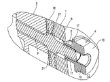
図1は、本発明によるスプロケットホイールカバー装置を備えた手で操縦されるパワーチェーンソーを示す図である。チェーンソーはケーシング2を有し、該ケーシング2内に内燃エンジン(図示せず)が配置されている。ケーシング2の側方には、通常の作業保持位置でケーシング2から前方へ突出するガイドレール18が配置され、該ガイドレール18のまわりには、内燃エンジンにより駆動される切断チェーン(図示せず)が周回するように案内されている。ケーシング2の上方中央部には前部グリップ19が配置されている。ケーシング2の、ガイドレール18とは逆の側の背面には、後部グリップ20が設けられている。両グリップ19,20を用いてチェーンソーが作動中に手で操縦される。
Next, embodiments of the present invention will be described in detail with reference to the accompanying drawings.
FIG. 1 is a diagram showing a manually operated power chain saw equipped with a sprocket wheel cover device according to the present invention. The chainsaw has a
内燃エンジンはスプロケットホイール(図示せず)を駆動する。スプロケットホイールの外側の歯は切断チェーンの鎖環の間に係合して切断チェーンを運動させる。スプロケットホイールと、ガイドレール18の、スプロケットホイールに境を接している部分とは、スプロケットホイールカバー1によって覆われている。ケーシング2には2つのスタッドボルト3,3’が固定されている。スタッドボルト3,3’には2つのナット4,4’がスプロケットホイールカバー1の外面12に接するように螺合している。ナット4,4’はスプロケットホイールカバー1をケーシング2に対し押圧させ、その際ガイドレール18はスプロケットホイールカバー1とケーシング2との間で締め付け固定される。
The internal combustion engine drives a sprocket wheel (not shown). The teeth on the outside of the sprocket wheel engage between the chain rings of the cutting chain to move the cutting chain. The sprocket wheel and the portion of the
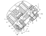
図2は図1の配置構成のスプロケットホイールカバー1の領域の展開図である。ケーシング2は支持穴26を有し、該支持穴26を、組み立て状態で駆動軸(図示せず)がスプロケットホイール(同様に図示せず)とともに貫通する。支持穴26を起点としてガイドレール18の方向に延びる前記2つのスタッドボルト3,3’がケーシング2に固定されている。両スタッドボルト3,3’は、そのスプロケットホイールカバー1の外面12側の端部に、それぞれねじ自由端5を有している。両スタッドボルト3,3’の間には、図3に図示したチェーンテンショナー24のための調整ねじ22が配置されている。
FIG. 2 is a development view of the region of the sprocket wheel cover 1 having the arrangement shown in FIG. The
ガイドレール18は、その支持穴26側の端部に、該ガイドレール18の長手軸線方向に延びているスリット21を有している。組み立て状態では両スタッドボルト3,3’はこのスリット21を貫通し、ガイドレール18の長手方向の移動を可能にさせる。ガイドレール18はスリット21の上方および下方にそれぞれ1つの穴23を備えている。組み立て状態では、チェーンテンショナー24の、図3に図示したピン25が、下部穴23に係合する。調整ねじ22を用いてチェーンテンショナー24を操作することにより、スプロケットホイールカバー1を取り外した状態でガイドレール18をその長手軸線18の方向へ位置調整して、図示していない切断チェーンの所望の張りを設定できる。
The
組み立て後の作動準備状態では、両スタッドボルト3,3’はスプロケットホイールカバー1の側壁を貫通してスプロケットホイールカバー1の外面12まで案内されている。その際両ナット4,4’は両スタッドボルト3,3’のそれぞれのねじ自由端5に螺合している。ナット4,4’を部分的に緩めた後、スプロケットホイールカバー1に設けた調整穴27を通じて調整ねじ22を操作し、チェーンの張りを修正することができる。ナット4,4’を完全に緩めた後、スプロケットホイールカバー1をケーシング2から取り外すことができ、ガイドレール18の取り外し或いは交換が可能である。
In an operation ready state after assembly, both
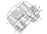
図3は図2の配置構成の変形実施形態であり、この実施形態ではただ1つのスタッドボルト3のみが調整ねじ22の手前に配置されている。後部のスタッドボルト3(図2)の代わりにねじ込みヘッド30が設けられている。ねじ込みヘッド30は組み立て状態でスタッドボルト3とともにガイドレール18のスリット21に係合する。これに対応して、スプロケットホイールカバー1には全部で1つのナット4が設けられているにすぎない。図3の配置構成は他の構成の点および符合の点で図2の配置構成と一致している。
FIG. 3 shows a modified embodiment of the arrangement of FIG. 2, in which only one
チェーンテンショナー24は、調整ねじ22以外に、ピン25が固定されている調整要素28を有している。調整要素28は調整ねじ22とウォーム伝動装置(図示せず)とを用いてガイドレール18の長手軸線に平行に二重矢印29の方向へ移動可能である。穴21に係合しているピン25はガイドレール18を同じ量だけ二重矢印29の方向へ移動させ、それによって切断チェーン(図示せず)の張りを調整することができる。同様のことは図2に図示していないチェーンテンショナーに対しても言える。
The
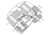
図4は図2の配置構成を組み立て状態で示した部分断面図である。この図からわかるように、スプロケットホイールカバー1はケーシング2に面で当接している。ガイドレール18はケーシング2とスプロケットホイールカバー1の当接面との間に面で締め付け固定されている。この状態でチェーンテンショナー24(図3)を操作することは不可能である。切断チェーンの選定された緊張状態は固定されている。ケーシング2に固定されているスタッドボルト3はガイドレール18とスプロケットホイールカバー1とを貫通している。ナット4は外面に取り付けられ、非締め付け状態で示してある。図2に図示した、ナット4’を付設した他のスタッドボルト3’の領域は、図4に図示した構成と同一に構成されている。
FIG. 4 is a partial cross-sectional view showing the arrangement configuration of FIG. 2 in an assembled state. As can be seen from this figure, the sprocket wheel cover 1 is in contact with the
図4においてVで示した部分を拡大したのが図5である。図5からわかるように、スタッドボルト3はケーシング2内にねじ込められている。このねじ込みは、作動条件の下でスタッドボルト3がケーシング2に相対回転不能に固定されるように実施されている。スタッドボルト3は、ケーシング2の外側に、拡径した鍔31を有している。拡径した鍔31はガイドレール18のスリット21に遊びなしに係合している。これによりガイドレール18は鉛直方向に形状拘束的に固定されている。
FIG. 5 is an enlarged view of a portion indicated by V in FIG. As can be seen from FIG. 5, the
ケーシング2は円形の開口部6を有し、該開口部6をスタッドボルト3が貫通している。スタットボルト3の径は、開口部6の領域において、鍔31および開口部6に比べて縮径されており、したがって組み立て状態では開口部6に環状自由空間が残る。ナット4は外面12の方向に操作部分16を備え、図示した実施形態では操作部分16は六角体として実施されている。ナット4はたとえば操作部分16にドライバーを当てることで回転させることができる。六角体として構成する代わりに、ナット4を手で操作するためにローレット等も合目的である。操作部分16には、ケーシング2の方向で、一体に成形された管状軸体17が接続している。管状軸体17はスプロケットホイールカバー1の開口部6に遊びを持って挿入されている。ナット4は管状軸体17の自由端において、後述する態様で紛失不能に且つ回転可能にスプロケットホイールカバー1の開口部6内で遊びを持って保持されている。
The
ナット4は、中央部に且つスタッドボルト3に同軸に穴を備えている。この穴は、スタッドボルト3側では平滑なスリーブ部分11として実施され、反対側では雌ねじ部分10として実施されている。図示した、ナット4を螺合させていない状態では、スタッドボルト3のねじ端5は雌ねじ部分10と螺合せずに、平滑なスリーブ部分11にゆるく係合している。
The nut 4 is provided with a hole at the center and coaxially with the
図6は図4の配置構成の両スタッドボルト3,3’の領域での縦断面図である。全部ナット4は図5の図示に対応して非締め付け状態で図示してある。他の後部ナット4’はその雌ねじ部分10が付設のスタッドボルト3’のねじ端5に螺合して、ガイドレール18を介してスプロケットホイールカバー1をケーシング2に対ししっかりと押圧させる。このため、ナット4,4’はそれぞれスプロケットホイールカバー1側で周回するように延びている鍔45を備えた鍔付きナットとして実施されている。鍔45はナットを締めた状態でスプロケットホイールカバー1の外面を面で押圧する。
FIG. 6 is a longitudinal sectional view in the region of both
同一に構成されている両ナット4,4’はその筒状の管状軸体7によって付設の開口部6に遊びを持って係合する。管状軸体17は、ケーシング2側の自由端に、半径方向外側へ指向するように周回して延びる突起15を備えている。開口部6内では、外面12側で、半径方向内側へ指向する保持縁14が周回するように延びている。保持縁14には、ナット4の周回するように延びている突起15が形状拘束的に係合している。これによりナット4はスプロケットホイールカバー1に形状拘束的に係合して紛失不能になっている。
Both nuts 4, 4 ′ configured identically engage with the
図示した実施形態では、スプロケットホイールカバー1は鋳造した軽金属(ここではマグネシウム)から形成され、保持縁14は鋳造技術的にスプロケットホイールカバー1の残りの部分と一体に成形されている。ナット4は金属、特に鋼から一体に製造され、図示していない加工前状態では周回する突起15をまだ有していない。組み立てのため、管状軸体17を開口部6内へ挿入して、管状軸体17の自由端が周回するように延びている保持縁14の内側に位置するようにする。次に管状軸体17の自由端をかしめて、材料変形により縁取りされた前記周回する突起15が形成されるようにする。この状態でナット4は紛失不能にスプロケットホイールカバー1で保持される。
In the illustrated embodiment, the sprocket wheel cover 1 is formed from a cast light metal (here magnesium) and the retaining
管状軸体17と開口部6との間には、半径方向の遊びrが残る。この遊びrはスプロケットホイールカバー1に対するナット4の回転自在性を可能にするものである。さらに、スタッドボルト3の長手軸線7に関し半径方向においてナット4を付設のスタッドボルト3に対し位置整合させることが可能である。さらに、操作部分16と周回するように延びている突起15との間における管状軸体17の長さから軸線方向の遊びsが生じる。また、この軸線方向の遊びsと前記半径方向の遊びrとの組み合わせにより、スプロケットホイールカバー1に対するナット4の傾動遊び(二重矢印9で示した)が生じる。
A radial play r remains between the
組み立て状態でガイドレール18から突出するスタッドボルト3の突出長さLと、保持縁14および突起15の位置決めと、スプロケットホイールカバー1内でのナット4の遊びとは、次のように互いに整合しており、すなわち図6の図示のようにスプロケットホイールカバー1を作動位置に取り付けた場合、ナット4とスタッドボルト3との螺合を完全に解除することができ、また完全に締める(螺合させる)こともできるように整合している。図では、説明のため、前部ナット4は完全に緩めた状態で図示されており、後部ナット4’は完全に締めた状態で図示してある。
The protruding length L of the
ナット4’を完全に締めた状態では、その雌ねじ部分10はねじ込み深さtにわたって付設のスタッドボルト3’のねじ端5に螺合する。
When the nut 4 ′ is completely tightened, the
ナット4’の軸線方向の遊びsは少なくとも前記ねじ込み深さtと同じ大きさである。これにより、ガイドレール18およびスプロケットホイールカバー1の位置を、図示した作動位置から変化させることなく、ナット4’を完全に締めたり緩めたりすることができる。
The play s in the axial direction of the nut 4 ′ is at least as large as the screwing depth t. Thereby, nut 4 'can be completely tightened or loosened, without changing the position of
さらに、スタッドボルト3の長さLと平滑なスリーブ部分11の長さlとは、スプロケットホイールカバー1を作動位置に取り付けてナット4をスプロケットホイールカバー1の外面12から完全に引き抜いた状態でスタッドボルト3が平滑なスリーブ部分11に係合するように互いに整合している。スプロケットホイールカバー1を取り付ける場合、スタッドボルト3,3’の両ねじ端5を付設のナット4,4’のそれぞれのスリーブ部分11に挿通させる。ナット4,4’は、挿通補助手段として、付設のスタッドボルト3,3’側に、それぞれスタッドボルトのための心合わせテーパ部13を有している。挿通させてスプロケットホイールカバー1をさらにスライドさせると、ねじ端5がスリーブ部分11からはみ出すことなく、ナット4,4’の外面12に対する遊びsを利用して該ナット4,4’をスライドさせることができる。
Further, the length L of the
スプロケットホイールカバー1を作動位置に取り付けた場合、両ナット4,4’は、ナット4の位置に関し図示したように、雌ねじ部分10が付設のねじ端5と係合していなくとも、付設のスタッドボルト3,3’に対し螺合準備状態で指向している。このような付設のスタッドボルト3,3’に対するナット4,4’の自動的な位置指向は、スプロケットホイールカバー1を斜めに傾斜して取り付けた場合も行なわれる。というのは、ナット4,4’の軸線方向の遊びs、半径方向の遊びr、傾動遊び9のために、該ナット4,4’はそれぞれのスリーブ部分11に挿通したときに付設スタッドボルト3,3’の位置に自動的に適合するからである。
When the sprocket wheel cover 1 is mounted in the operating position, both nuts 4 and 4 ′ are provided with the provided studs even if the
ガイドレール18を取り付けるため、ガイドレール18を少なくとも1つのスタッドボルト3の上に載置する。次にスプロケットホイールカバー1を取り付けるが、その際少なくとも1つのナット4は付設のスタッドボルト3に対し自動的に指向する。スプロケットホイールカバー1を押さえつけることにより、ガイドレール18を仮固定する。1個のスタッドボルト3と1個のナット4のみで実施する場合には、次に指向完了状態にあり且つ紛失不能に保持されているナット4を締めるだけでよい。2個のスタッドボルト3,3’と2個のナット4,4’で実施する場合には、両ナット4,4’を互いに独立に締めてよい。この場合、操作しなかったナット4または4’は紛失不能に位置保持される。
In order to mount the
図7は図6の配置構成の変形実施形態である。ここではスプロケットホイールカバー1は射出成形されるプラスチックから製造されている。開口部6を形成するため、スプロケットホイールカバー1のプラスチック材料のなかに金属から成るスリーブ32、特に鋼またはアルミニウムから成るスリーブ32を挿入する。スリーブ32にはそれぞれ保持縁14が一体成形されている。一体成形されたナット4の突起15の領域には、突起15を形成させるためのかしめ工程または縁取り工程を容易にするスリット33が設けられている。
FIG. 7 shows a modified embodiment of the arrangement shown in FIG. Here, the sprocket wheel cover 1 is manufactured from injection-molded plastic. In order to form the
図8の実施形態では、管状軸体17は、突起15を一体成形した弾性的なロック舌片34が生じるように、複数個のスリット33を備えている。取り付けのために変形工程は必要ない。むしろ、ロック舌片34の弾性変位を利用してナット4を開口部6に差し込めばよい。この場合ロック舌片34の突起15は保持縁14の後方にスナップ固定されて、ナットの位置を形状拘束的に固定する。
In the embodiment of FIG. 8, the
これとは択一的に、図9の実施形態に対応して、スリット35を備えたロック舌片36を、プラスチックから製造されたスプロケットホイールカバー1に挿入したスリーブ32に形成させるのも合目的である。
Alternatively, corresponding to the embodiment of FIG. 9, it is also possible to form a locking
図10の実施形態では、ナット4は2分割して形成されている。スリーブ部分11と雌ねじ10とを備えた、金属から成る内側スリーブ38は、内側からスプロケットホイールカバー1の開口部6を通して外面12のほうへ差し込まれ、外面12上で、ナット4を形成させるための把持部分37と結合されている。把持部分37も同様に金属から成っていてよく、たとえば内側スリーブ38に圧着されている。工具なしで操作するため、把持部分37をたとえばプラスチックから構成するのも合目的である。
In the embodiment of FIG. 10, the nut 4 is divided into two parts. An
図11の実施形態では、図10の配置構成に比べて逆の構成になっている。2分割のナット4は、雌ねじ部分10とスリーブ部分11の少なくとも一部分とを備えたナット部分40を有している。スリーブ部分11は外面を外側スリーブ39によって取り囲まれている。組み立ては図10の実施形態に比較可能に次のようにして行い、すなわち外側スリーブ39を内側から外面12のほうへ案内し、ナット部分40を外面12から開口部6内へ案内するようにして行なう。次に、変形工程を行なう必要なしに、両部材を結合させる。
In the embodiment of FIG. 11, the configuration is the reverse of the arrangement configuration of FIG. The two-part nut 4 has a
本発明の他の実施形態を図12に示す。ナット4は図6の実施形態と同様に一体に形成されている。スプロケットホイールカバー1に挿着されるスリーブ32は、その内面に、周回するように延びる止め輪41を担持している。止め輪41はスリーブ32の周回するように延びている溝42のなかで保持されている。止め輪41はナット4の突起15のための保持縁14を形成している。
Another embodiment of the present invention is shown in FIG. The nut 4 is integrally formed as in the embodiment of FIG. The
図12の実施形態とは択一的に、図13の実施形態も合目的である。この実施形態では、ナット4の管状軸体17の外周に溝44が形成されている。溝44には、ナット44の周回するように延びている突起15を形成している止め輪43が挿着されている。なお、スリーブ32は図7の実施形態に対応して構成されている。
As an alternative to the embodiment of FIG. 12, the embodiment of FIG. 13 is also suitable. In this embodiment, a groove 44 is formed on the outer periphery of the
図7ないし図13に図示した個々の実施形態は、以上説明した以外の構成および符号に関し相互に一致しているとともに、図6の実施形態とも一致している。個々の実施形態の異なる構成は互いに任意に組み合わせてよい。 Each of the embodiments shown in FIGS. 7 to 13 is identical to the embodiment shown in FIG. 6 as well as to the configuration and reference numerals other than those described above. Different configurations of the individual embodiments may be arbitrarily combined with each other.
1 スプロケットホイールカバー
2 ケーシング
3,3’ スタッドボルト
4,4’ ナット
5 ねじ端
6 開口部
7 スタッドボルトの長手軸線
9 傾動遊び
10 雌ねじ部分
11 平滑なスリーブ部分
11 スリーブ部分
12 スプロケットホイールカバーの外面
14 保持縁
16 操作部分
17 管状軸体
18 ガイドレール
L スタッドボルトの長さ
l 平滑なスリーブ部分の長さ
r 半径方向の遊び
s 軸線方向の遊び
t ねじ込み深さ
DESCRIPTION OF SYMBOLS 1
Claims (10)
ナット(4)が紛失不能に、回転可能に、且つ遊びを持ってスプロケットホイールカバー(1)の前記開口部(6)内で保持され、前記遊びがスタッドボルト(3)の長手軸線(7)に関し軸線方向の遊び(s)を含み、該軸線方向の遊び(s)が、少なくとも、ナット(4)へのスタッドボルト(3)の所定のねじ込み深さ(t)と同じ大きさであることを特徴とするスプロケットホイールカバー装置。 A sprocket wheel cover device for a chain saw operated by hand, the sprocket wheel cover (1), the casing (2), and the casing (2) fixed to the sprocket wheel cover (1) with the casing (2) At least one stud bolt (3) for screwing, and a screw free end (5) of the stud bolt (3) guided through the opening (6) of the sprocket wheel cover (1) in the assembled state In the sprocket wheel cover device having a nut (4) to be screwed,
Nut (4) is non lost, rotatably and with play is held by the opening of the sprocket wheel cover (1) (6) in the play longitudinal axis of the stud bolt (3) (7) The axial play (s) is at least as large as the predetermined threading depth (t) of the stud bolt (3) into the nut (4). Sprocket wheel cover device.
Applications Claiming Priority (2)
| Application Number | Priority Date | Filing Date | Title |
|---|---|---|---|
| DE102006037329.4 | 2006-08-10 | ||
| DE102006037329.4A DE102006037329B4 (en) | 2006-08-10 | 2006-08-10 | Sprocket cover assembly of a hand-held chainsaw |
Publications (2)
| Publication Number | Publication Date |
|---|---|
| JP2008044095A JP2008044095A (en) | 2008-02-28 |
| JP5227545B2 true JP5227545B2 (en) | 2013-07-03 |
Family
ID=38922010
Family Applications (1)
| Application Number | Title | Priority Date | Filing Date |
|---|---|---|---|
| JP2007183414A Active JP5227545B2 (en) | 2006-08-10 | 2007-07-12 | Sprocket wheel cover device for manually operated chainsaw |
Country Status (5)
| Country | Link |
|---|---|
| US (1) | US8132484B2 (en) |
| JP (1) | JP5227545B2 (en) |
| CN (1) | CN101121272B (en) |
| DE (1) | DE102006037329B4 (en) |
| FR (1) | FR2904787B1 (en) |
Families Citing this family (22)
| Publication number | Priority date | Publication date | Assignee | Title |
|---|---|---|---|---|
| EP2777901B1 (en) * | 2007-10-12 | 2017-05-17 | Husqvarna AB | Attaching arrangement for hand-held motor-driven tools |
| JP5146912B2 (en) * | 2008-05-23 | 2013-02-20 | 日立工機株式会社 | Chainsaw |
| DE102010012748B4 (en) * | 2010-03-25 | 2020-01-02 | Andreas Stihl Ag & Co. Kg | chainsaw |
| CN102398312A (en) * | 2010-09-09 | 2012-04-04 | 北京凌天世纪自动化技术有限公司 | Hydraulic diamond chain saw |
| US8696277B2 (en) * | 2011-06-22 | 2014-04-15 | Caterpillar Inc. | Captive fastener assembly and machine using same |
| CN103291844A (en) * | 2012-03-02 | 2013-09-11 | 博世电动工具(中国)有限公司 | Electric tool and transmission device thereof |
| DE102012010963A1 (en) | 2012-05-31 | 2013-12-05 | Andreas Stihl Ag & Co. Kg | Implement with sprocket cover |
| DE102012010977A1 (en) * | 2012-05-31 | 2013-12-05 | Andreas Stihl Ag & Co. Kg | "Hand-held implement with a cutting chain for cutting mineral or metallic materials" |
| JP6132626B2 (en) * | 2013-03-29 | 2017-05-24 | 株式会社マキタ | Portable work machine |
| JP6137467B2 (en) * | 2013-04-25 | 2017-05-31 | 日立工機株式会社 | Chainsaw |
| JP6152325B2 (en) * | 2013-09-11 | 2017-06-21 | 株式会社やまびこ | Tightening nut retaining structure and tightening nut anchoring member in portable power work machine |
| DE202013105469U1 (en) | 2013-12-02 | 2015-03-03 | Makita Corporation | Fastening arrangement, portable working device for attaching a first housing part to a second housing part |
| DE102014004526A1 (en) * | 2014-03-27 | 2015-10-01 | Andreas Stihl Ag & Co. Kg | Hand-held implement |
| EP3237158B1 (en) * | 2014-12-22 | 2021-07-28 | Husqvarna AB | Fastener retention device for a guard cover |
| EP3053717B1 (en) | 2015-02-03 | 2020-06-10 | Andreas Stihl AG & Co. KG | Work device |
| JP6588326B2 (en) * | 2015-12-17 | 2019-10-09 | 株式会社やまびこ | Retaining structure for tightening nut in portable power working machine and method for assembling the tightening nut |
| DE102016000718A1 (en) * | 2016-01-23 | 2017-07-27 | Andreas Stihl Ag & Co. Kg | Hand-operated implement with a guide rail |
| EP3629702A4 (en) * | 2017-06-02 | 2020-06-24 | JPS Teknik AB | Arrangement for replacing a saw chain on a motor saw |
| JP6999429B2 (en) * | 2018-01-12 | 2022-01-18 | 株式会社マキタ | Chainsaw |
| US11343973B2 (en) * | 2018-05-23 | 2022-05-31 | Milwaukee Electric Tool Corporation | Pole saw |
| SE543228C2 (en) | 2018-11-06 | 2020-10-27 | Husqvarna Ab | Chainsaw with constrasting fillings in housing |
| CN110756900A (en) * | 2019-11-15 | 2020-02-07 | 泰州市汇顶机械制造有限公司 | Domestic electric chain saw with thermal-insulated function |
Family Cites Families (19)
| Publication number | Priority date | Publication date | Assignee | Title |
|---|---|---|---|---|
| GB995840A (en) * | 1900-01-01 | |||
| US2078411A (en) * | 1935-07-05 | 1937-04-27 | F L Mclaughlin Company | Clinch-on nut |
| JPS6038701U (en) * | 1983-08-25 | 1985-03-18 | 小松ゼノア株式会社 | Chienso |
| DE4142751C1 (en) * | 1991-12-23 | 1992-12-17 | Fa. Andreas Stihl, 7050 Waiblingen, De | Motor-driven chain-saw - has guide-plate with rear end held in place by fitting into shoulders on motor housing |
| JPH0723501U (en) * | 1993-10-13 | 1995-05-02 | 小松ゼノア株式会社 | Chainsaw |
| DE29614832U1 (en) * | 1996-08-26 | 1997-01-02 | Trw Repa Gmbh | Fasteners in a vehicle occupant restraint system |
| US6095733A (en) * | 1998-06-29 | 2000-08-01 | Huck International, Inc. | Threaded fastener with determinable clamp load |
| DE29812098U1 (en) * | 1998-07-08 | 1998-09-10 | Stihl Maschf Andreas | Fastening device for an adjustable and clamped component |
| DE19846555A1 (en) * | 1998-10-09 | 2000-04-13 | Dolmar Gmbh | Tensioning device for chain or belt of motorized hand-held tool, with length of journal made so that bolt only projects when journal is in aperture of washer |
| DE29909645U1 (en) | 1999-06-02 | 1999-09-16 | Narex Ceska Lipa As | Screw connection, in particular for fastening the sword of a chainsaw |
| DE19931250A1 (en) | 1999-07-07 | 2001-01-11 | Bosch Gmbh Robert | chainsaw |
| JP3712594B2 (en) | 2000-05-19 | 2005-11-02 | 株式会社マキタ | Chainsaw |
| ITVE20000042A1 (en) | 2000-10-17 | 2002-04-17 | Alpina Professional & Garden S | TENSIONING DEVICE, PARTICULARLY FOR CHAIN CHAINSAWS |
| EP1637299B1 (en) * | 2003-05-20 | 2009-02-25 | Husqvarna Zenoah Co., Ltd. | Auto chain tensioner |
| ITVE20030013U1 (en) | 2003-07-08 | 2005-01-09 | Ggp Italy Spa | TENSIONING DEVICE FOR CHAIN SAWS OR CHAINSAWS. - |
| DE102005007203A1 (en) * | 2004-10-15 | 2006-04-20 | Gustav Klauke Gmbh | Lug with nut or functional part, method for producing such a cable lug and nut |
| US7250003B2 (en) * | 2005-07-21 | 2007-07-31 | Thompson Steven L | Encapsulated fastener and method and tooling for manufacturing same |
| US7743513B1 (en) * | 2006-10-31 | 2010-06-29 | Mtd Products Inc | Chainsaw tensioning device |
| DE102010012748B4 (en) * | 2010-03-25 | 2020-01-02 | Andreas Stihl Ag & Co. Kg | chainsaw |
-
2006
- 2006-08-10 DE DE102006037329.4A patent/DE102006037329B4/en active Active
-
2007
- 2007-07-12 JP JP2007183414A patent/JP5227545B2/en active Active
- 2007-08-09 US US11/836,161 patent/US8132484B2/en active Active
- 2007-08-10 CN CN2007101408677A patent/CN101121272B/en active Active
- 2007-08-10 FR FR0705813A patent/FR2904787B1/en active Active
Also Published As
| Publication number | Publication date |
|---|---|
| DE102006037329B4 (en) | 2020-01-02 |
| CN101121272A (en) | 2008-02-13 |
| US20080034597A1 (en) | 2008-02-14 |
| FR2904787A1 (en) | 2008-02-15 |
| FR2904787B1 (en) | 2015-03-13 |
| JP2008044095A (en) | 2008-02-28 |
| US8132484B2 (en) | 2012-03-13 |
| CN101121272B (en) | 2012-06-13 |
| DE102006037329A1 (en) | 2008-02-14 |
Similar Documents
| Publication | Publication Date | Title |
|---|---|---|
| JP5227545B2 (en) | Sprocket wheel cover device for manually operated chainsaw | |
| JP4732448B2 (en) | Vehicle belt drive torsion bar tensioner with improved braking system | |
| TW408072B (en) | Multiple sprocket assembly adapted to secure a sprocket to an outer race | |
| US5919106A (en) | Quick release derailleur | |
| US10214051B2 (en) | Rear wheel axle, as well as bicycle frame and rear wheel for a bicycle | |
| US20210131547A1 (en) | Sub-assembly sprocket-carrying body and cogset for a bicycle rear wheel, ring nut for fixing such a sub-assembly and method for fixing a cogset to a sprocket-carrying body | |
| JP7059074B2 (en) | Rotating body removal tool and how to remove the rotating body | |
| KR100783530B1 (en) | A mounting jig rear oil seal | |
| EP1151357A1 (en) | Method for fixing a crown screwed on a watch case and watch case equipped with same | |
| US6293883B1 (en) | Quick release derailleur | |
| JP4174800B2 (en) | Solenoid valve, its mounting and fixing method, and component mounting fixture for mounting and fixing solenoid valve, sensor, potentiometer, flow sensor and other accessory parts | |
| JP2005042832A (en) | Fastener of shaft and rotating body | |
| WO2016087730A1 (en) | Assembly comprising a wheel rim and a hub cap provided with an axial-locking hub | |
| US10677213B2 (en) | Electrical starter system for the retrofit of motorcycles | |
| CN105835010A (en) | Power Tool | |
| US7520357B1 (en) | Method of installing cruise control for a motorcycle | |
| US20110058895A1 (en) | Device for fixing accessories in a motorcycle, in particular for a windshield | |
| JP2007132493A (en) | Fixing structure of ball screw nut for steering | |
| JP6036651B2 (en) | Rotating jig for assembly | |
| JP2006207692A (en) | Rotor fixing device | |
| KR200287866Y1 (en) | locking tool of flywheel for an automobile engine service | |
| TWI810001B (en) | Bicycle tools mounted on the bicycle body | |
| JPH07299765A (en) | Pulley puller | |
| JP5480876B2 (en) | Engine accessory removal method and accessory mounting structure | |
| JP4463376B2 (en) | Tensioner |
Legal Events
| Date | Code | Title | Description |
|---|---|---|---|
| A621 | Written request for application examination |
Free format text: JAPANESE INTERMEDIATE CODE: A621 Effective date: 20100629 |
|
| A131 | Notification of reasons for refusal |
Free format text: JAPANESE INTERMEDIATE CODE: A131 Effective date: 20120731 |
|
| A601 | Written request for extension of time |
Free format text: JAPANESE INTERMEDIATE CODE: A601 Effective date: 20121030 |
|
| A602 | Written permission of extension of time |
Free format text: JAPANESE INTERMEDIATE CODE: A602 Effective date: 20121102 |
|
| A601 | Written request for extension of time |
Free format text: JAPANESE INTERMEDIATE CODE: A601 Effective date: 20121129 |
|
| A602 | Written permission of extension of time |
Free format text: JAPANESE INTERMEDIATE CODE: A602 Effective date: 20121204 |
|
| A601 | Written request for extension of time |
Free format text: JAPANESE INTERMEDIATE CODE: A601 Effective date: 20121227 |
|
| A602 | Written permission of extension of time |
Free format text: JAPANESE INTERMEDIATE CODE: A602 Effective date: 20130107 |
|
| A521 | Request for written amendment filed |
Free format text: JAPANESE INTERMEDIATE CODE: A523 Effective date: 20130130 |
|
| TRDD | Decision of grant or rejection written | ||
| A01 | Written decision to grant a patent or to grant a registration (utility model) |
Free format text: JAPANESE INTERMEDIATE CODE: A01 Effective date: 20130226 |
|
| A61 | First payment of annual fees (during grant procedure) |
Free format text: JAPANESE INTERMEDIATE CODE: A61 Effective date: 20130318 |
|
| R150 | Certificate of patent or registration of utility model |
Ref document number: 5227545 Country of ref document: JP Free format text: JAPANESE INTERMEDIATE CODE: R150 Free format text: JAPANESE INTERMEDIATE CODE: R150 |
|
| FPAY | Renewal fee payment (event date is renewal date of database) |
Free format text: PAYMENT UNTIL: 20160322 Year of fee payment: 3 |
|
| R250 | Receipt of annual fees |
Free format text: JAPANESE INTERMEDIATE CODE: R250 |
|
| R250 | Receipt of annual fees |
Free format text: JAPANESE INTERMEDIATE CODE: R250 |
|
| R250 | Receipt of annual fees |
Free format text: JAPANESE INTERMEDIATE CODE: R250 |
|
| R250 | Receipt of annual fees |
Free format text: JAPANESE INTERMEDIATE CODE: R250 |
|
| R250 | Receipt of annual fees |
Free format text: JAPANESE INTERMEDIATE CODE: R250 |
|
| R250 | Receipt of annual fees |
Free format text: JAPANESE INTERMEDIATE CODE: R250 |
|
| R250 | Receipt of annual fees |
Free format text: JAPANESE INTERMEDIATE CODE: R250 |
|
| R250 | Receipt of annual fees |
Free format text: JAPANESE INTERMEDIATE CODE: R250 |
|
| R250 | Receipt of annual fees |
Free format text: JAPANESE INTERMEDIATE CODE: R250 |