JP5225820B2 - Input device, vehicle periphery monitoring device, icon switch selection method and program - Google Patents
Input device, vehicle periphery monitoring device, icon switch selection method and program Download PDFInfo
- Publication number
- JP5225820B2 JP5225820B2 JP2008300197A JP2008300197A JP5225820B2 JP 5225820 B2 JP5225820 B2 JP 5225820B2 JP 2008300197 A JP2008300197 A JP 2008300197A JP 2008300197 A JP2008300197 A JP 2008300197A JP 5225820 B2 JP5225820 B2 JP 5225820B2
- Authority
- JP
- Japan
- Prior art keywords
- screen
- icon
- virtual pointer
- icon switch
- displayed
- Prior art date
- Legal status (The legal status is an assumption and is not a legal conclusion. Google has not performed a legal analysis and makes no representation as to the accuracy of the status listed.)
- Active
Links
- 238000012806 monitoring device Methods 0.000 title claims description 14
- 238000010187 selection method Methods 0.000 title claims description 11
- 238000000034 method Methods 0.000 claims description 24
- 238000012545 processing Methods 0.000 claims description 21
- 238000003384 imaging method Methods 0.000 claims description 14
- 230000008569 process Effects 0.000 claims description 9
- 238000012544 monitoring process Methods 0.000 claims description 8
- 238000004891 communication Methods 0.000 description 4
- 238000001514 detection method Methods 0.000 description 4
- 230000008859 change Effects 0.000 description 2
- 238000010586 diagram Methods 0.000 description 2
- 230000006870 function Effects 0.000 description 2
- 230000003287 optical effect Effects 0.000 description 2
- 230000003247 decreasing effect Effects 0.000 description 1
- 230000006872 improvement Effects 0.000 description 1
- 230000004048 modification Effects 0.000 description 1
- 238000012986 modification Methods 0.000 description 1
- 230000007935 neutral effect Effects 0.000 description 1
Images


Classifications
-
- G—PHYSICS
- G06—COMPUTING; CALCULATING OR COUNTING
- G06F—ELECTRIC DIGITAL DATA PROCESSING
- G06F3/00—Input arrangements for transferring data to be processed into a form capable of being handled by the computer; Output arrangements for transferring data from processing unit to output unit, e.g. interface arrangements
- G06F3/01—Input arrangements or combined input and output arrangements for interaction between user and computer
- G06F3/048—Interaction techniques based on graphical user interfaces [GUI]
- G06F3/0481—Interaction techniques based on graphical user interfaces [GUI] based on specific properties of the displayed interaction object or a metaphor-based environment, e.g. interaction with desktop elements like windows or icons, or assisted by a cursor's changing behaviour or appearance
-
- G—PHYSICS
- G01—MEASURING; TESTING
- G01C—MEASURING DISTANCES, LEVELS OR BEARINGS; SURVEYING; NAVIGATION; GYROSCOPIC INSTRUMENTS; PHOTOGRAMMETRY OR VIDEOGRAMMETRY
- G01C21/00—Navigation; Navigational instruments not provided for in groups G01C1/00 - G01C19/00
- G01C21/26—Navigation; Navigational instruments not provided for in groups G01C1/00 - G01C19/00 specially adapted for navigation in a road network
- G01C21/34—Route searching; Route guidance
- G01C21/36—Input/output arrangements for on-board computers
- G01C21/3664—Details of the user input interface, e.g. buttons, knobs or sliders, including those provided on a touch screen; remote controllers; input using gestures
-
- B—PERFORMING OPERATIONS; TRANSPORTING
- B60—VEHICLES IN GENERAL
- B60R—VEHICLES, VEHICLE FITTINGS, OR VEHICLE PARTS, NOT OTHERWISE PROVIDED FOR
- B60R1/00—Optical viewing arrangements; Real-time viewing arrangements for drivers or passengers using optical image capturing systems, e.g. cameras or video systems specially adapted for use in or on vehicles
- B60R1/02—Rear-view mirror arrangements
- B60R1/04—Rear-view mirror arrangements mounted inside vehicle
-
- B—PERFORMING OPERATIONS; TRANSPORTING
- B60—VEHICLES IN GENERAL
- B60R—VEHICLES, VEHICLE FITTINGS, OR VEHICLE PARTS, NOT OTHERWISE PROVIDED FOR
- B60R25/00—Fittings or systems for preventing or indicating unauthorised use or theft of vehicles
-
- G—PHYSICS
- G01—MEASURING; TESTING
- G01C—MEASURING DISTANCES, LEVELS OR BEARINGS; SURVEYING; NAVIGATION; GYROSCOPIC INSTRUMENTS; PHOTOGRAMMETRY OR VIDEOGRAMMETRY
- G01C21/00—Navigation; Navigational instruments not provided for in groups G01C1/00 - G01C19/00
- G01C21/26—Navigation; Navigational instruments not provided for in groups G01C1/00 - G01C19/00 specially adapted for navigation in a road network
- G01C21/34—Route searching; Route guidance
- G01C21/36—Input/output arrangements for on-board computers
-
- G—PHYSICS
- G06—COMPUTING; CALCULATING OR COUNTING
- G06F—ELECTRIC DIGITAL DATA PROCESSING
- G06F3/00—Input arrangements for transferring data to be processed into a form capable of being handled by the computer; Output arrangements for transferring data from processing unit to output unit, e.g. interface arrangements
- G06F3/01—Input arrangements or combined input and output arrangements for interaction between user and computer
- G06F3/048—Interaction techniques based on graphical user interfaces [GUI]
- G06F3/0481—Interaction techniques based on graphical user interfaces [GUI] based on specific properties of the displayed interaction object or a metaphor-based environment, e.g. interaction with desktop elements like windows or icons, or assisted by a cursor's changing behaviour or appearance
- G06F3/04817—Interaction techniques based on graphical user interfaces [GUI] based on specific properties of the displayed interaction object or a metaphor-based environment, e.g. interaction with desktop elements like windows or icons, or assisted by a cursor's changing behaviour or appearance using icons
-
- B—PERFORMING OPERATIONS; TRANSPORTING
- B60—VEHICLES IN GENERAL
- B60R—VEHICLES, VEHICLE FITTINGS, OR VEHICLE PARTS, NOT OTHERWISE PROVIDED FOR
- B60R2300/00—Details of viewing arrangements using cameras and displays, specially adapted for use in a vehicle
- B60R2300/10—Details of viewing arrangements using cameras and displays, specially adapted for use in a vehicle characterised by the type of camera system used
- B60R2300/105—Details of viewing arrangements using cameras and displays, specially adapted for use in a vehicle characterised by the type of camera system used using multiple cameras
-
- G—PHYSICS
- G06—COMPUTING; CALCULATING OR COUNTING
- G06F—ELECTRIC DIGITAL DATA PROCESSING
- G06F2203/00—Indexing scheme relating to G06F3/00 - G06F3/048
- G06F2203/01—Indexing scheme relating to G06F3/01
- G06F2203/014—Force feedback applied to GUI
Description
本発明は、入力装置、車両周辺監視装置、アイコンスイッチ選択方法及びプログラムに係り、更に詳しくは、アイコンスイッチを選択することにより所望の指令を入力する入力装置、前記入力装置を備える車両周辺監視装置、画面に表示されたアイコンスイッチを選択するアイコンスイッチ選択方法、及び情報を表示する表示装置の制御を行う制御装置に用いられるプログラムに関する。 The present invention relates to an input device, a vehicle periphery monitoring device, an icon switch selection method, and a program. More specifically, the input device inputs a desired command by selecting an icon switch, and a vehicle periphery monitoring device including the input device. The present invention relates to an icon switch selection method for selecting an icon switch displayed on a screen, and a program used for a control device that controls a display device that displays information.
車両に搭載されるナビゲーション装置や、車両の周辺を監視する車両周辺監視装置の操作は、一般に画面に表示された複数のアイコンスイッチが、リモコンなどの遠隔操作装置やタッチパネル等を介して選択されることにより行われる。 For operation of a navigation device mounted on a vehicle or a vehicle periphery monitoring device for monitoring the periphery of the vehicle, generally, a plurality of icon switches displayed on the screen are selected via a remote control device such as a remote control or a touch panel. Is done.
通常、この種の装置を操作するには、例えばジョイスティックなどの選択スイッチを備えた遠隔操作装置や、タッチパネルなどを操作することにより、画面に表示されたポインタなどの指示マークを、所望のアイコンスイッチに重ね合わせる操作が必要になる。このため、ユーザは装置を操作する際に、ある程度の時間画面を注視する必要があった。 Usually, in order to operate this type of device, for example, a remote control device having a selection switch such as a joystick, or a touch panel or the like is used to display an instruction mark such as a pointer displayed on the screen with a desired icon switch. It is necessary to superimpose them. For this reason, the user needs to watch the screen for a certain amount of time when operating the apparatus.
そこで、近年ではユーザの負担を軽減する観点から、アイコンスイッチ上に指示マークを移動する際にユーザの動作をアシストして、ユーザが画面を注視する時間を短縮化することを目的とする方法が種々提案されている(例えば特許文献1乃至特許文献3参照)。 Therefore, in recent years, from the viewpoint of reducing the burden on the user, there is a method aimed at assisting the user's operation when moving the instruction mark on the icon switch and reducing the time for the user to watch the screen. Various proposals have been made (see, for example, Patent Documents 1 to 3).
特許文献1に記載の方法は、ユーザが指示マークを所望のアイコンスイッチに移動しようとする際に、遠隔操作手段を操作するユーザに対して、指示マークの位置に対応するアイコンスイッチに応じた抵抗力を感知させるものである。これによれば、ユーザは、感知した抵抗力に逆らわずに、遠隔操作手段を操作することで、長時間画面を注視することなく、指示マークを所望のアイコンスイッチに容易に重ね合わせることができる。 In the method described in Patent Document 1, when a user tries to move an instruction mark to a desired icon switch, a resistance corresponding to the icon switch corresponding to the position of the instruction mark is provided to the user who operates the remote control means. It senses force. According to this, the user can easily superimpose the instruction mark on the desired icon switch without gazing at the screen for a long time by operating the remote control means without countering the sensed resistance. .
また、特許文献2に記載の方法は、画面内の指示マークがアイコンスイッチを含む領域に含まれる場合に、指示マークの位置をアイコンスイッチ上に移動させるものである。また、特許文献3に記載の方法は、画面に表示されたアイコンスイッチそれぞれと指示マークとの距離を算出し、指示マークを最も近くにあるアイコンスイッチ上に移動させるものである。これらの方法では、ユーザは指示マークの位置を完全にアイコンスイッチと重ね合わせる必要がないので、所望のアイコンスイッチを簡単に選択することができる。 The method described in Patent Document 2 moves the position of the instruction mark onto the icon switch when the instruction mark on the screen is included in the area including the icon switch. The method described in Patent Document 3 calculates the distance between each icon switch displayed on the screen and the instruction mark, and moves the instruction mark onto the nearest icon switch. In these methods, the user does not need to completely overlap the position of the instruction mark with the icon switch, so that a desired icon switch can be easily selected.
しかしながら、上述の方法では、アイコンスイッチのいずれかに指示マークを位置決めしようとすると、ユーザは画面上のアイコンスイッチ相互間の領域においても、指示マークの位置を意識し、かつ指示マークを所望のアイコンスイッチへ移動させる動作を継続する必要がある。特に、車両に搭載される車両周辺監視装置などでは、交通の安全を確保する観点から、ユーザの操作負担を極力低減させることが望ましい。 However, in the above-described method, when the instruction mark is to be positioned on one of the icon switches, the user is aware of the position of the instruction mark even in the area between the icon switches on the screen, and the instruction mark is placed on the desired icon. It is necessary to continue the movement to the switch. In particular, in a vehicle periphery monitoring device or the like mounted on a vehicle, it is desirable to reduce a user's operation burden as much as possible from the viewpoint of ensuring traffic safety.
本発明は、上述の事情の下になされたもので、その第1の目的は、短時間のうちに容易に所望の指令を入力することが可能な入力装置を提供することにある。 The present invention has been made under the circumstances described above, and a first object of the invention is to provide an input device capable of easily inputting a desired command within a short time.
また、本発明の第2の目的は、容易に操作することが可能な車両周辺監視装置を提供することにある。 A second object of the present invention is to provide a vehicle periphery monitoring device that can be easily operated.
また、本発明の第3の目的は、短時間のうちに容易に所望のアイコンスイッチを選択することを可能とするアイコンスイッチ選択方法を提供することにある。 A third object of the present invention is to provide an icon switch selection method that makes it possible to easily select a desired icon switch in a short time.
また、本発明の第4の目的は、表示画面を制御する制御装置に実行させることで、短時間のうちに容易に所望のアイコンスイッチを選択することを可能とするプログラムを提供することにある。 A fourth object of the present invention is to provide a program that allows a control device that controls a display screen to execute a desired icon switch easily in a short time. .
本発明の第1の観点にかかる入力装置は、所定の装置に指令を入力するための入力装置であって、外部からの入力によって画面内を移動する、外部から視認されない仮想ポインタを規定するとともに、前記画面を区分することにより規定した複数の領域それぞれの一部に、前記指令に対応し相互に異なる処理内容が割り当てられた複数のアイコンスイッチを、前記領域ごとに1つずつ表示する表示手段と、複数の前記領域のうちの1つの前記領域に、前記仮想ポインタの位置が含まれる場合に、前記仮想ポインタの位置が前記アイコンスイッチまで移動しなくても、前記仮想ポインタの位置を含む前記領域に表示された前記アイコンスイッチを選択する選択手段と、前記アイコンスイッチと前記仮想ポインタとが重ならなくても、前記選択手段によって選択されたアイコンスイッチに対応する処理内容を含む情報を前記所定の装置に出力する処理を開始することが可能である処理手段と、を備え、前記画面上のすべての範囲が、前記複数の領域のいずれかに割り当てられていることを特徴とする。 An input device according to a first aspect of the present invention is an input device for inputting a command to a predetermined device, and defines a virtual pointer that moves within the screen by an external input and is not visually recognized from the outside. Display means for displaying a plurality of icon switches each assigned a different processing content corresponding to the command to a part of each of the plurality of areas defined by dividing the screen And when the position of the virtual pointer is included in one of the plurality of areas, the position of the virtual pointer includes the position of the virtual pointer even if the position of the virtual pointer does not move to the icon switch. selection means for selecting the icon switch displayed in the region, without overlap with the icon switch and the virtual pointer, the selected manual And a processing unit it is possible to start processing of outputting the information including the processing content corresponding to the icon switch selected to the predetermined device by, all ranges on the screen, the plurality of It is assigned to one of the areas.
また、前記領域は、表示される前記アイコンスイッチの使用頻度に応じて大きさが規定されることとしてもよい。 The size of the area may be defined according to the frequency of use of the icon switch to be displayed .
本発明の第2の観点にかかる車両周辺監視装置は、車両の周辺を監視する車両周辺監視装置であって、本発明の入力装置と、前記車両の周辺の画像を撮像する撮像手段と、を備え、前記撮像手段によって撮像された画像は、前記入力装置の前記画面に、前記アイコンスイッチと重畳して表示されることを特徴とする。 A vehicle periphery monitoring device according to a second aspect of the present invention is a vehicle periphery monitoring device that monitors the periphery of a vehicle, the input device of the present invention, and an imaging unit that captures an image of the periphery of the vehicle. The image picked up by the image pickup means is displayed on the screen of the input device so as to be superimposed on the icon switch.
本発明の第3の観点にかかるアイコンスイッチ選択方法は、画面に表示された複数のアイコンスイッチのいずれかを選択するアイコンスイッチ選択方法であって、外部からの入力によって画面内を移動する、外部から視認されない仮想ポインタを規定する工程と、前記画面を区分することにより、前記画面上のすべての範囲に割り当てられるように規定した複数の領域それぞれの一部に、相互に異なる処理内容が割り当てられた複数のアイコンスイッチを、前記領域ごとに1つずつ表示する工程と、複数の前記領域のうちの1つの前記領域に、前記仮想ポインタの位置が含まれる場合に、前記仮想ポインタの位置が前記アイコンスイッチまで移動しなくても、前記仮想ポインタの位置を含む前記領域に表示された前記アイコンスイッチを選択する工程と、前記アイコンスイッチと前記仮想ポインタとが重ならなくても、選択された前記アイコンスイッチに対応する処理内容を含む情報を所定の装置に出力する工程と、を含むことを特徴とする。 An icon switch selection method according to a third aspect of the present invention is an icon switch selection method for selecting one of a plurality of icon switches displayed on the screen, and the external switch moves within the screen by an external input. By defining the virtual pointer that is not visually recognized from the screen, and by dividing the screen, different processing contents are allocated to a part of each of the plurality of areas defined to be allocated to all ranges on the screen. And displaying the plurality of icon switches one by one for each of the areas, and when the position of the virtual pointer is included in one of the plurality of areas, the position of the virtual pointer is Selects the icon switch displayed in the area including the position of the virtual pointer without moving to the icon switch And that step, without overlap with the icon switch and the virtual pointer, characterized in that it comprises a step of outputting information including the process contents corresponding to the icon switch selected to a predetermined device, the .
本発明の第4の観点にかかるプログラムは、情報を表示する表示装置の制御を行う制御装置に、外部からの入力によって画面内を移動する、外部から視認されない仮想ポインタを規定する手順と、前記画面を区分することにより、前記画面上のすべての範囲に割り当てられるように規定した複数の領域それぞれの一部に、相互に異なる処理内容が割り当てられた複数のアイコンスイッチを、前記領域ごとに1つずつ表示する手順と、複数の前記領域のうちの1つの前記領域に、前記仮想ポインタの位置が含まれる場合に、前記仮想ポインタの位置が前記アイコンスイッチまで移動しなくても、前記仮想ポインタの位置を含む前記領域に表示された前記アイコンスイッチを選択する手順と、前記アイコンスイッチと前記仮想ポインタとが重ならなくても、選択された前記アイコンスイッチに対応する処理内容を含む情報を所定の装置に出力する手順と、を実行させることを特徴とする。
A program according to a fourth aspect of the present invention provides a control device that controls a display device that displays information, a procedure for defining a virtual pointer that moves within the screen by an external input and is not visually recognized from the outside, By dividing the screen, a plurality of icon switches in which different processing contents are assigned to a part of each of the plurality of areas defined to be assigned to all ranges on the screen are assigned to each area. The virtual pointer is displayed even if the position of the virtual pointer is not moved to the icon switch when the position of the virtual pointer is included in one of a plurality of the areas. overlap and procedures for selecting the icon switch displayed in the region including the position, and the virtual pointer and the icon switch Without having, characterized in that to execute a procedure for outputting information including the process contents corresponding to the icon switch selected to a predetermined device.
所望の指令を短時間に容易に入力することができる。また、複数のアイコンスイッチが表示された画面を注視する時間を短縮することができる。 A desired command can be easily input in a short time. In addition, it is possible to reduce the time required to gaze at a screen on which a plurality of icon switches are displayed.
以下本発明の一実施形態を図1〜図5に基づいて説明する。図1は、本実施形態にかかるナビゲーション装置100の概略構成を示すブロック図である。このナビゲーション装置100は、一例として車両に搭載される装置であり、図1に示されるように、ユーザからの入力に応じて変調された例えば赤外線信号を出力する遠隔操作装置20と、遠隔操作装置20から出力された信号に基づいて動作するシステム本体10とを有している。
Hereinafter, an embodiment of the present invention will be described with reference to FIGS. FIG. 1 is a block diagram illustrating a schematic configuration of a
システム本体10は、インターフェイス11、情報受信装置12、位置検出センサ13、外部メモリ14、撮像装置15、情報記憶装置16、制御装置17、表示装置18、及び音声出力装置19を含んで構成されている。
The system
前記インターフェイス11は、遠隔操作装置20から出力された赤外線信号を受信し、受信した赤外線信号を電気信号に変換して制御装置17へ出力する。
The interface 11 receives the infrared signal output from the
前記情報受信装置12は、全地球測位システム(GPS:Global Positioning System)から送信される情報を受信し、ナビゲーション装置100が搭載された車両の現在位置情報、現在時刻などを制御装置17へ出力する。なお、この情報受信装置12は、例えばFM多重放送、電波ビーコン、光ビーコンなどを利用して交通情報を取得するVICS(Vehicle Information and Communication System)情報受信装置、携帯電話などの情報通信端末を利用して、例えばATIS(Advanced Traffic Information Service)などの情報センターや他の車両との情報通信を行うことが可能な通信装置を含んで構成されていてもよい。
The
前記位置検出センサ13は、例えば、地磁気センサ、ジャイロセンサ、車速センサなどの各種センサを含んで構成されている。そして、車両の移動に伴う位置の変化量を検出し、検出した変化量を含む情報を制御装置17へ出力する。
The position detection sensor 13 includes, for example, various sensors such as a geomagnetic sensor, a gyro sensor, and a vehicle speed sensor. Then, a change amount of the position accompanying the movement of the vehicle is detected, and information including the detected change amount is output to the
前記外部メモリ14には、地図情報をはじめとして、ルート探索及びルート案内などに用いられる目的地データ、登録地点データなどの情報が記録されている。この外部メモリ14としては、例えばCD、DVDなどの光ディスク、ハードディスク、フラッシュメモリなどを用いることができる。 The external memory 14 stores information such as map information, destination data used for route search and route guidance, registration point data, and the like. As this external memory 14, for example, an optical disk such as a CD or a DVD, a hard disk, a flash memory, or the like can be used.
前記撮像装置15は、一例として車両のドアミラー又はサイドミラーに設けられた1組のカメラを有し、このカメラによって撮像された画像情報を、制御装置17へ出力する。
The imaging device 15 has, as an example, a pair of cameras provided on a door mirror or side mirror of a vehicle, and outputs image information captured by the camera to the
前記情報記憶装置16は、例えばSDRAM、HDDなどから構成され、上述の外部メモリ14に格納されたデータを用いて、ルート探索、ルート案内、及び車両周辺監視などを行うための各種プログラムが格納されている。また、この情報記憶装置16は、例えばユーザから入力された操作内容を含んだ情報や、車両の移動経路を含んだ情報などの履歴情報を逐次記憶する。
The
前記表示装置18は、制御装置17から供給される情報を表示する。図2は、表示装置18を示す平面図である。図2に示されるように、表示装置18は長方形状の画面18aを有している。また、画面18aには、例えば図2における左下の隅を原点(0,0)とするXY座標が規定され、画面内の位置は原点座標(0,0)から右上隅の座標(xm,ym)までの座標値によって特定される。
The
図1に戻り、前記音声出力装置19は、スピーカなどから構成され、制御装置17から供給される経路案内等の情報を音声出力する。
Returning to FIG. 1, the
前記制御装置17は、CPU(中央演算処理装置)を含んで構成され、情報記憶装置16に記憶されたプログラムを実行して、ルート探索及びルート案内などを行い、その結果を、表示装置18及び音声出力装置19へ出力する。
The
前記遠隔操作装置20は、一例としてジョイスティックと、決定ボタンを含む複数の押しボタンを備えている。ユーザは遠隔操作装置20に設けられたジョイスティックなどを操作することで、例えば、ナビゲーション装置100の機能の選択、目的地及び検索条件などの入力を、インターフェイス11を介して制御装置17に入力することができる。
The
次に、上述のように構成されたナビゲーション装置100の操作方法について説明する。ナビゲーション装置100が起動されると、制御装置17は、情報記憶装置16に記憶されている種々のプログラムを実行して、情報受信装置12から供給される位置情報に基づいて車両の現在位置を算出し、この算出した現在位置を例えば位置検出センサ13からの情報に基づいて補正した状態で、表示装置18の画面18aに地図情報とともに表示する。また、この状態のときには、表示装置18の画面18aには、例えば車両周辺監視を行うためのアイコンスイッチ18b1を含む複数のアイコンスイッチ18b1〜18b6と、これら複数のアイコンスイッチ18b1〜18b6を選択するためのポインタPが表示される。
Next, an operation method of the
ここでユーザが車両周辺監視を行う場合には、遠隔操作装置20のジョイスティックを操作することによりポインタPを移動させて、ポインタPをアイコンスイッチ18b1に重ね合わせる。そして、この状態から遠隔操作装置20の決定ボタンを押下する。これにより、図3のフローチャートに示されるプログラムが実行され、ユーザは車両周辺監視を行うことが可能となる。
Here, when the user performs a vehicle periphery monitoring moves the pointer P by operating the joystick of the
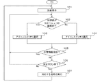
図3のフローチャートは、制御装置17によって実行されるプログラムの一連の処理アルゴリズムに対応している。以下、図3を参照しつつ車両周辺監視を行う場合の制御装置17による処理内容を説明する。
The flowchart in FIG. 3 corresponds to a series of processing algorithms of a program executed by the
まず、最初のステップ101では、制御装置17は表示装置18の画面18aに初期画面を表示する。図4を参酌するとわかるように、この初期画面は、例えば、撮像装置15によって撮像された画像と、アイコンスイッチ1及びアイコンスイッチ2とから構成されている。また、図4に示されるように、この初期画面が表示されているときには、画面18aには領域A1と領域A2の2つの領域が規定され、アイコンスイッチ1及びアイコンスイッチ2は、それぞれ領域A1及び領域A2に表示された状態となっている。
First, in the
なお、本実施形態では、視認できる境界線によって画面が区分されることにより各領域A1,A2が規定されている訳ではなく、例えば制御装置17が、原点座標(0,0)から座標(x1,ym)で規定される長方形の領域を領域A1として規定し、X座標の値が座標(x1,ym)よりも1単位大きい座標(x1+1,0)から座標(xm,ym)で規定される長方形の領域を領域A2として規定することにより、画面上のすべての範囲がいずれかの領域(ここでは領域A1及び領域A2)に割り当てられる。
In the present embodiment, the areas A1 and A2 are not defined by dividing the screen by a visually recognizable boundary line. For example, the
また、この状態のとき制御装置17は、画面上のいずれかの位置、例えば画面の中心位置に視認されない仮想のポインタP’(以下、仮想ポインタP’という)を規定する。この仮想ポインタP’は、ユーザに視認されることはないが、遠隔操作装置20から出力される位置情報によって画面内を移動するものである。
In this state, the
次のステップ102では、制御装置17は、表示装置18の画面18aに規定された仮想ポインタP’の位置座標(x,y)を検出し、この位置座標(x,y)が、(0,0)から(x1,ym)の範囲にあるか、すなわち仮想ポインタP’の位置座標が領域A1に含まれるか否かを判断する。ここでの判断が肯定された場合には、ステップ103へ移行し、否定された場合には、ステップ104へ移行する。
In the
ステップ103では、制御装置17は、領域A1に表示されたアイコンスイッチ1を選択し、また、ステップ104では、領域A2に表示されたアイコンスイッチ2を選択する。なお、本実施形態のナビゲーション装置100では、選択されたアイコンスイッチは、例えば選択前の表示色以外の色で表示され、あるいは縁取りした状態で表示される。これにより、ユーザは容易に選択されたアイコンスイッチを識別することができる。
In
次のステップ105では、制御装置17は、遠隔操作装置20からの位置情報を受信したか否かを判断する。この位置情報には、画面上の位置を特定するための座標(x,y)に関する情報が含まれており、ユーザが遠隔操作装置20に設けられたジョイスティックを操作することで、遠隔操作装置20から出力される。以下、説明の便宜上、遠隔操作装置20から出力され、制御装置17に受信される座標を受信座標(x,y)とする。制御装置17は、ステップ105での判断が肯定された場合、すなわち受信座標(x,y)を含む位置情報を受信した場合には、受信座標(x,y)に対応する画面上の位置に仮想ポインタP’を移動し、ステップ102に戻る。以下、ステップ105での判断が否定されるまでステップ102〜ステップ105までの処理が繰り返される。
In the
一方、ステップ105での判断が否定された場合には、次のステップ106へ移行する。
On the other hand, if the determination in
ステップ106では、制御装置17は、遠隔操作装置20に設けられた決定ボタンが押下されたか否かを判断する。この判断は、例えば遠隔操作装置20から出力された所定の信号を受信したか否かにより行うことができる。
In
制御装置17は、ステップ106での判断が否定された場合には、ステップ102に戻り、以降ステップ106での判断が肯定されるまで、ステップ102〜ステップ106までの一連の処理を繰り返し行う。これにより、ユーザがジョイスティックを操作することで、仮想ポインタP’が、例えば図5に示される矢印aに沿って領域A1から領域A2へ移動する。そして、仮想ポインタP’の移動にともなって、仮想ポインタP’が含まれていた領域A1に表示されたアイコンスイッチ1の選択が解除され、仮想ポインタP’の移動先の位置が含まれる領域A2に表示されたアイコンスイッチ2が新たに選択される。また、不図示ではあるが、仮想ポインタP’が領域A2から領域A1へ移動した場合には、仮想ポインタP’の移動にともなって、仮想ポインタP’が含まれていた領域A2に表示されたアイコンスイッチ2の選択が解除され、仮想ポインタP’の移動先の位置が含まれる領域A1に表示されたアイコンスイッチ1が新たに選択される。
If the determination in
一方、ステップ106での判断が肯定された場合には、次のステップ107へ移行する。
On the other hand, if the determination at
ステップ107では、制御装置17は、遠隔操作装置20の決定ボタンが押下されたときに選択されていたアイコンスイッチに対応する処理を開始する。そして、当該処理が完了したら、ステップ101に戻る。
In
以降の処理では、表示装置18の画面18aには、ステップ107で行われた処理に対応した画面がそれぞれ表示される。したがって、ユーザは、遠隔操作装置20を操作することにより、画面18aに表示された各処理に対応するアイコンスイッチを適宜選択していくことで、撮像装置15の各種操作を行い、撮像装置15によって撮像された画像を画面18aを介して見ることができる。
In the subsequent processing, a screen corresponding to the processing performed in
なお、撮像装置15の操作を中断する場合には、撮像装置15の操作を中断する機能が割り当てられたアイコンスイッチを表示装置18の画面18aに表示するようにして、ユーザにこのアイコンスイッチを選択させるようにすればよい。
When the operation of the imaging device 15 is interrupted, an icon switch to which a function for interrupting the operation of the imaging device 15 is assigned is displayed on the
以上説明したように、本実施形態では、表示装置18の画面18aが2つの領域A1及び領域A2に区分され、仮想ポインタP’の位置を含む領域に表示されたアイコンスイッチが選択される。これにより、画面18aに表示されたアイコンスイッチ1及びアイコンスイッチ2のうちのいずれかが常時選択された状態となる。したがって、ユーザは、例えば従来の装置のように、画面を注視して視認可能なポインタなどの指示マークを所望のアイコンスイッチまで移動させるための動作を行う必要がなくなり、短時間のうちに容易に所望のアイコンスイッチを選択することができる。また、これによりユーザは画面を長時間注視することなく、所望の指令を入力することができる。したがって、ユーザの負担を軽減することが可能となる。
As described above, in the present embodiment, the
また、本実施形態では、撮像装置15の操作を行う際には表示装置18の画面18a上に視認可能なポインタ等の指示マークが表示されないので、撮像装置15によって撮像され、画面18aに表示された画像の視認性が妨げられることがない。これにより、画面に表示された表示対象物の視認性の向上が実現される。また、車両の周辺監視が行われているときであっても、システム本体10は仮想ポインタに基づいて操作される。これにより、ユーザは、視認可能なポインタ等で装置の操作を行うナビゲーション時と同様の操作感で、車両の周辺監視を違和感なく行うことができる。
Further, in the present embodiment, when operating the imaging device 15, since an instruction mark such as a visible pointer is not displayed on the
なお、本実施形態では、遠隔操作装置20から仮想ポインタP’の座標(x,y)を含む情報が出力されることとしたが、これに限らず、遠隔監視装置20からは、仮想ポインタP’の現在位置の座標を増減するための情報を含む信号が出力されることとしてもよい。この場合には、仮想ポインタP’のX座標値及びY座標値が連続的に増減し、仮想ポインタP’は、ユーザからの指示により表示装置18の画面18a上を連続的に移動する。そして、仮想ポインタP’の位置を含む領域にあるアイコンスイッチが順次選択される。
In the present embodiment, information including the coordinates (x, y) of the virtual pointer P ′ is output from the
また、本実施形態にかかる遠隔操作装置20は、ジョイスティック及び決定ボタンを備えているが、これに限らず、例えばジョイスティックに代えて、ジョグダイヤルや方向キーなどを備えていてもよい。要は、遠隔操作装置20は、仮想ポインタP’の位置情報を出力できる構成、あるいは、仮想ポインタP’の位置座標を増減させることができる構成であればよい。
The
また、本実施形態では、遠隔操作装置20とシステム本体10とは、赤外線を用いて通信を行うこととしたが、これに限らず、遠隔操作装置20とシステム本体10とは、ケーブルなどにより電気的に接続され、このケーブルを介して通信を行うこととしてもよい。
In the present embodiment, the
また、遠隔操作装置20に代えて、例えばタッチパネルなどの入力装置を用いて、仮想ポインタP’を移動することとしてもよい。この場合にも、画面上に表示されたアイコンスイッチのいずれかが常時選択されるため、ユーザは容易に所望のアイコンスイッチを選択することができ、結果的に画面を注視する時間が短縮される。
Further, the virtual pointer P ′ may be moved using an input device such as a touch panel instead of the
また、本実施形態では、図5を参酌するとわかるように、表示装置18の画面18aが2つに区分されることで、画面18aに2つの領域が規定された場合について説明したが、これに限らず、例えば図6に示されるように、画面18aを3つ、またはそれ以上に区分して、それぞれの領域にアイコンスイッチ1〜3を表示することとしてもよい。この場合にも、仮想ポインタP’の位置が含まれる領域に表示されたアイコンスイッチが常時選択された状態となるので、ユーザは容易に所望のアイコンスイッチを選択することができ、結果的に画面を注視する時間が短縮される。
Further, in the present embodiment, as described with reference to FIG. 5, the case where the
また、アイコンスイッチが表示される領域は、表示されるアイコンスイッチの使用頻度、重要性などに応じて、その大きさを設定することとしてもよい。これにより、使用頻度の高いアイコンスイッチほど選択容易性が向上するため、ユーザの操作負担を更に軽減することが可能となる。 Further, the size of the area in which the icon switch is displayed may be set according to the usage frequency, importance, etc. of the icon switch to be displayed. Thereby, since an icon switch with higher use frequency improves ease of selection, it is possible to further reduce the operation burden on the user.
また、選択されたアイコンスイッチが変わった場合には、そのタイミングで操作装置のジョイスティック等に抵抗力を作用させるようにしてもよい。これにより、ユーザは選択されたアイコンスイッチが切り替わったことを容易に認識できるため、更に正確に所望のアイコンスイッチを選択することが可能となる。なお、遠隔操作装置20のジョイスティックに抵抗力を作用させる技術は、例えば特許文献1(特開2004−252760号公報)に詳細に記載されている。つまり、仮想ポインタが、現在選択されているアイコンスイッチが属する領域から、所望のアイコンスイッチが表示された他の領域に移動したタイミングで、例えばユーザによって傾倒された遠隔操作装置20のジョイスティックをニュートラル方向へ戻すような力(抵抗力)を作用させる。これにより、ユーザは、この抵抗力に従ってジョイスティックを操作することで、仮想ポインタを所望のアイコンスイッチが含まれる領域へ容易に移動させて、所望のアイコンスイッチを簡単に選択することができる。また、ユーザはこの抵抗力に反して、ジョイスティックの傾倒を継続させることで、他の領域へ仮想ポインタを移動させることができる。
When the selected icon switch is changed, a resistance force may be applied to the joystick or the like of the operating device at that timing. As a result, the user can easily recognize that the selected icon switch has been switched, so that the desired icon switch can be selected more accurately. A technique for applying a resistance force to the joystick of the
なお、本実施形態では、仮想ポインタP’を用いた説明を行ったが、仮想ポインタを定義することなく、制御装置が、本来視認可能なポインタを表示すべき位置の座標を認識し、この認識された座標値に対応した画面上の位置を含む領域のアイコンスイッチを選択することとしてもよい。 In the present embodiment, the description has been made using the virtual pointer P ′. However, without defining the virtual pointer, the control device recognizes the coordinates of the position where the originally visible pointer should be displayed. An icon switch in an area including a position on the screen corresponding to the coordinate value thus set may be selected.
また、本実施形態で説明したアイコンスイッチ選択方法及び入力装置は、車両用の周辺監視装置に限らず、他の移動手段に用いられる周辺監視装置に対しても好適である。また、周辺監視装置に限らず、例えばバックモニタ、及び車載カメラの表示画面などに表示されたアイコンスイッチの選択にも好適である。 Further, the icon switch selection method and the input device described in the present embodiment are not limited to the vehicle periphery monitoring device, but are also suitable for the periphery monitoring device used for other moving means. Moreover, it is suitable not only for the periphery monitoring device but also for selecting an icon switch displayed on a back monitor, a display screen of a vehicle-mounted camera, or the like.
また、場合によっては、車両のナビゲーションを行う場合に表示される画面、例えばルート探索を実行する際に目的地などの条件を入力するための画面や、地図と現在位置を表示してルート案内などを行う画面に表示されたアイコンスイッチを選択する場合にも、本発明にかかるアイコンスイッチ選択方法及び入力装置を用いることができる。この場合にも、ユーザは容易に所望のアイコンスイッチを選択することができるので、結果的に画面を注視する時間を短縮することができる。また、画面に表示されたアイコンなどの指示マークによる、画面の視認性の低下を回避することができる。 Also, in some cases, a screen displayed when performing vehicle navigation, for example, a screen for inputting conditions such as a destination when performing route search, a route guidance by displaying a map and the current position, etc. The icon switch selection method and the input device according to the present invention can also be used when selecting an icon switch displayed on the screen for performing the operation. Also in this case, the user can easily select a desired icon switch, and as a result, it is possible to shorten the time for watching the screen. Further, it is possible to avoid a decrease in screen visibility due to an instruction mark such as an icon displayed on the screen.
1〜3…アイコンスイッチ
10…システム本体
11…インターフェイス
12…情報受信装置
13…位置検出センサ
14…外部メモリ
15…撮像装置(撮像手段)
16…情報記憶装置
17…制御装置(選択手段、処理手段、制御手段)
18…表示装置(表示手段)
18a…画面
18b…アイコンスイッチ
19…音声出力装置
20…遠隔操作装置
100…ナビゲーション装置
A1,A2…領域
P…ポインタ
P’…仮想ポインタ
DESCRIPTION OF SYMBOLS 1-3 ...
16 ...
18. Display device (display means)
18a ... screen 18b ...
Claims (5)
外部からの入力によって画面内を移動する、外部から視認されない仮想ポインタを規定するとともに、前記画面を区分することにより規定した複数の領域それぞれの一部に、前記指令に対応し相互に異なる処理内容が割り当てられた複数のアイコンスイッチを、前記領域ごとに1つずつ表示する表示手段と、
複数の前記領域のうちの1つの前記領域に、前記仮想ポインタの位置が含まれる場合に、前記仮想ポインタの位置が前記アイコンスイッチまで移動しなくても、前記仮想ポインタの位置を含む前記領域に表示された前記アイコンスイッチを選択する選択手段と、
前記アイコンスイッチと前記仮想ポインタとが重ならなくても、前記選択手段によって選択されたアイコンスイッチに対応する処理内容を含む情報を前記所定の装置に出力する処理を開始することが可能である処理手段と、
を備え、
前記画面上のすべての範囲が、前記複数の領域のいずれかに割り当てられている入力装置。 An input device for inputting a command to a predetermined device,
Defines a virtual pointer that moves within the screen by external input and is not visible from the outside, and processes different from each other corresponding to the command in a part of each of the plurality of areas defined by dividing the screen Display means for displaying a plurality of icon switches assigned to each one of the areas;
When the position of the virtual pointer is included in one of the plurality of areas, the area including the position of the virtual pointer may be included even if the position of the virtual pointer does not move to the icon switch. Selecting means for selecting the displayed icon switch;
Even if the icon switch and the virtual pointer do not overlap each other, it is possible to start a process of outputting information including processing contents corresponding to the icon switch selected by the selection unit to the predetermined device Means,
With
An input device in which the entire range on the screen is assigned to one of the plurality of regions.
請求項1に記載の入力装置と、
前記車両の周辺の画像を撮像する撮像手段と、
を備え、
前記撮像手段によって撮像された画像は、前記入力装置の前記画面に、前記アイコンスイッチと重畳して表示される車両周辺監視装置。 A vehicle periphery monitoring device for monitoring the periphery of a vehicle,
An input device according to claim 1;
Imaging means for capturing an image of the periphery of the vehicle;
With
A vehicle periphery monitoring device in which an image picked up by the image pickup means is displayed superimposed on the icon switch on the screen of the input device.
外部からの入力によって画面内を移動する、外部から視認されない仮想ポインタを規定する工程と、
前記画面を区分することにより、前記画面上のすべての範囲に割り当てられるように規定した複数の領域それぞれの一部に、相互に異なる処理内容が割り当てられた複数のアイコンスイッチを、前記領域ごとに1つずつ表示する工程と、
複数の前記領域のうちの1つの前記領域に、前記仮想ポインタの位置が含まれる場合に、前記仮想ポインタの位置が前記アイコンスイッチまで移動しなくても、前記仮想ポインタの位置を含む前記領域に表示された前記アイコンスイッチを選択する工程と、
前記アイコンスイッチと前記仮想ポインタとが重ならなくても、選択された前記アイコンスイッチに対応する処理内容を含む情報を所定の装置に出力する工程と、
を含むアイコンスイッチ選択方法。 An icon switch selection method for selecting one of a plurality of icon switches displayed on a screen,
A step of defining a virtual pointer that moves within the screen by an external input and is not visible from the outside;
By dividing the screen, a plurality of icon switches assigned different processing contents to a part of each of the plurality of regions defined to be assigned to all ranges on the screen are provided for each region. Displaying one by one;
When the position of the virtual pointer is included in one of the plurality of areas, the area including the position of the virtual pointer may be included even if the position of the virtual pointer does not move to the icon switch. Selecting the displayed icon switch;
Outputting the information including the processing content corresponding to the selected icon switch to a predetermined device even if the icon switch and the virtual pointer do not overlap;
Icon switch selection method including
外部からの入力によって画面内を移動する、外部から視認されない仮想ポインタを規定する手順と、
前記画面を区分することにより、前記画面上のすべての範囲に割り当てられるように規定した複数の領域それぞれの一部に、相互に異なる処理内容が割り当てられた複数のアイコンスイッチを、前記領域ごとに1つずつ表示する手順と、
複数の前記領域のうちの1つの前記領域に、前記仮想ポインタの位置が含まれる場合に、前記仮想ポインタの位置が前記アイコンスイッチまで移動しなくても、前記仮想ポインタの位置を含む前記領域に表示された前記アイコンスイッチを選択する手順と、
前記アイコンスイッチと前記仮想ポインタとが重ならなくても、選択された前記アイコンスイッチに対応する処理内容を含む情報を所定の装置に出力する手順と、
を実行させるプログラム。 In the control device that controls the display device that displays information,
A procedure for defining a virtual pointer that moves within the screen by external input and is not visible from the outside,
By dividing the screen, a plurality of icon switches assigned different processing contents to a part of each of the plurality of regions defined to be assigned to all ranges on the screen are provided for each region. The procedure to display one by one,
When the position of the virtual pointer is included in one of the plurality of areas, the area including the position of the virtual pointer may be included even if the position of the virtual pointer does not move to the icon switch. A procedure for selecting the displayed icon switch;
Even if the icon switch and the virtual pointer do not overlap, a procedure for outputting information including the processing content corresponding to the selected icon switch to a predetermined device;
A program that executes
Priority Applications (8)
| Application Number | Priority Date | Filing Date | Title |
|---|---|---|---|
| JP2008300197A JP5225820B2 (en) | 2008-11-25 | 2008-11-25 | Input device, vehicle periphery monitoring device, icon switch selection method and program |
| US13/130,982 US9041804B2 (en) | 2008-11-25 | 2009-11-20 | Input device, vehicle environment monitoring apparatus, icon switch selection method, and recording medium |
| SG2011037579A SG171806A1 (en) | 2008-11-25 | 2009-11-20 | Input device, vehicle environment monitoring apparatus, icon switch selection method, and program |
| MYPI2011002339A MY179238A (en) | 2008-11-25 | 2009-11-20 | Input device, vehicle environment monitoring apparatus, icon switch selection method, and program |
| CN2009801472350A CN102224479B (en) | 2008-11-25 | 2009-11-20 | Input device, apparatus for monitoring area around vehicle, method for selecting icon switch, and program |
| KR1020117011945A KR101360328B1 (en) | 2008-11-25 | 2009-11-20 | Input device, apparatus for monitoring area around vehicle, method for selecting icon switch, and program |
| EP09829045.5A EP2360557B1 (en) | 2008-11-25 | 2009-11-20 | Input device, apparatus for monitoring area around vehicle, method for selecting icon switch, and program |
| PCT/JP2009/069729 WO2010061797A1 (en) | 2008-11-25 | 2009-11-20 | Input device, apparatus for monitoring area around vehicle, method for selecting icon switch, and program |
Applications Claiming Priority (1)
| Application Number | Priority Date | Filing Date | Title |
|---|---|---|---|
| JP2008300197A JP5225820B2 (en) | 2008-11-25 | 2008-11-25 | Input device, vehicle periphery monitoring device, icon switch selection method and program |
Publications (3)
| Publication Number | Publication Date |
|---|---|
| JP2010128619A JP2010128619A (en) | 2010-06-10 |
| JP2010128619A5 JP2010128619A5 (en) | 2011-06-16 |
| JP5225820B2 true JP5225820B2 (en) | 2013-07-03 |
Family
ID=42225673
Family Applications (1)
| Application Number | Title | Priority Date | Filing Date |
|---|---|---|---|
| JP2008300197A Active JP5225820B2 (en) | 2008-11-25 | 2008-11-25 | Input device, vehicle periphery monitoring device, icon switch selection method and program |
Country Status (8)
| Country | Link |
|---|---|
| US (1) | US9041804B2 (en) |
| EP (1) | EP2360557B1 (en) |
| JP (1) | JP5225820B2 (en) |
| KR (1) | KR101360328B1 (en) |
| CN (1) | CN102224479B (en) |
| MY (1) | MY179238A (en) |
| SG (1) | SG171806A1 (en) |
| WO (1) | WO2010061797A1 (en) |
Families Citing this family (18)
| Publication number | Priority date | Publication date | Assignee | Title |
|---|---|---|---|---|
| US20110258581A1 (en) * | 2010-04-14 | 2011-10-20 | Wei-Han Hu | Method for adjusting size of an icon and related handheld device |
| JP5516992B2 (en) | 2010-11-30 | 2014-06-11 | アイシン精機株式会社 | Parking position adjustment device |
| KR20130107697A (en) * | 2012-03-23 | 2013-10-02 | (주)휴맥스 | Apparatus and method for displaying background screen of navigation device |
| WO2014020994A1 (en) * | 2012-07-31 | 2014-02-06 | 古野電気株式会社 | Meteorological information display system, human navigation device, and meteorological information display method |
| JP5529943B2 (en) * | 2012-09-21 | 2014-06-25 | 株式会社小松製作所 | Work vehicle periphery monitoring system and work vehicle |
| EP2770413A3 (en) * | 2013-02-22 | 2017-01-04 | Samsung Electronics Co., Ltd. | An apparatus for providing a cursor in electronic devices and a method thereof |
| JP6371589B2 (en) * | 2014-05-27 | 2018-08-08 | アルパイン株式会社 | In-vehicle system, line-of-sight input reception method, and computer program |
| US9734412B2 (en) * | 2014-09-25 | 2017-08-15 | Nissan North America, Inc. | Method and system of communicating vehicle information |
| JP6321214B2 (en) * | 2014-12-25 | 2018-05-09 | アイシン・エィ・ダブリュ株式会社 | Display control system, method and program |
| CN105405483A (en) * | 2015-11-03 | 2016-03-16 | 上海核工程研究设计院 | Integrated frame system generation method based on operation unit |
| US10102358B2 (en) * | 2015-12-29 | 2018-10-16 | Sensory, Incorporated | Face-controlled liveness verification |
| JP6997106B2 (en) * | 2016-06-27 | 2022-01-17 | モービルアイ ビジョン テクノロジーズ リミテッド | Systems, methods and computer programs for navigating vehicles |
| JP6508173B2 (en) | 2016-11-25 | 2019-05-08 | トヨタ自動車株式会社 | Vehicle display device |
| JP6565878B2 (en) * | 2016-11-25 | 2019-08-28 | トヨタ自動車株式会社 | Display system |
| CN108255400A (en) * | 2017-11-30 | 2018-07-06 | 北京九五智驾信息技术股份有限公司 | Car-mounted terminal operating method and car-mounted terminal |
| DE102018204750A1 (en) * | 2018-03-28 | 2019-10-17 | Volkswagen Aktiengesellschaft | A method of adjusting the operation of a vehicle control system, apparatus for use in the method, and motor vehicle and computer program |
| US10898801B2 (en) * | 2019-06-03 | 2021-01-26 | Valve Corporation | Selecting properties using handheld controllers |
| US10866721B1 (en) * | 2019-09-20 | 2020-12-15 | Valve Corporation | Selecting properties using handheld controllers |
Family Cites Families (20)
| Publication number | Priority date | Publication date | Assignee | Title |
|---|---|---|---|---|
| US5757358A (en) * | 1992-03-31 | 1998-05-26 | The United States Of America As Represented By The Secretary Of The Navy | Method and apparatus for enhancing computer-user selection of computer-displayed objects through dynamic selection area and constant visual feedback |
| JPH0887395A (en) | 1994-09-20 | 1996-04-02 | Hitachi Ltd | Icon menu selection system, and system and information processor for same |
| JP3904637B2 (en) * | 1996-09-13 | 2007-04-11 | 株式会社東芝 | Information input device and method |
| JPH10240445A (en) | 1997-02-25 | 1998-09-11 | Kobe Nippon Denki Software Kk | Pointing device coordinate position correction system |
| US6426761B1 (en) * | 1999-04-23 | 2002-07-30 | Internation Business Machines Corporation | Information presentation system for a graphical user interface |
| WO2002005081A1 (en) * | 2000-05-11 | 2002-01-17 | Nes Stewart Irvine | Zeroclick |
| US6919866B2 (en) * | 2001-02-06 | 2005-07-19 | International Business Machines Corporation | Vehicular navigation system |
| JP2004078678A (en) * | 2002-08-20 | 2004-03-11 | Hitachi Ltd | Display device provided with touch panel |
| JP4089461B2 (en) | 2003-02-20 | 2008-05-28 | 株式会社デンソー | Remote control device and remote control method |
| JP4064870B2 (en) * | 2003-06-03 | 2008-03-19 | 株式会社竹中工務店 | Information processing apparatus, command execution method, and command execution program |
| JP2005215749A (en) * | 2004-01-27 | 2005-08-11 | Nec Corp | Selection system and selection method of operating element |
| JP2006215963A (en) * | 2005-02-07 | 2006-08-17 | Tokai Rika Co Ltd | Touch type input device |
| JP2006244393A (en) * | 2005-03-07 | 2006-09-14 | Tokai Rika Co Ltd | Input device |
| US20060226298A1 (en) * | 2005-03-30 | 2006-10-12 | Lionel L.L.C. | Graphical method and system for model vehicle and accessory control |
| JP4645299B2 (en) * | 2005-05-16 | 2011-03-09 | 株式会社デンソー | In-vehicle display device |
| JP4880304B2 (en) * | 2005-12-28 | 2012-02-22 | シャープ株式会社 | Information processing apparatus and display method |
| JP4488012B2 (en) | 2007-02-27 | 2010-06-23 | トヨタ自動車株式会社 | Vehicle travel support device |
| JP5088669B2 (en) * | 2007-03-23 | 2012-12-05 | 株式会社デンソー | Vehicle periphery monitoring device |
| JP4924164B2 (en) * | 2007-04-09 | 2012-04-25 | パナソニック株式会社 | Touch input device |
| JP2008300197A (en) | 2007-05-31 | 2008-12-11 | Tokai Rika Hanbai Kk | Ignition switch device |
-
2008
- 2008-11-25 JP JP2008300197A patent/JP5225820B2/en active Active
-
2009
- 2009-11-20 CN CN2009801472350A patent/CN102224479B/en active Active
- 2009-11-20 MY MYPI2011002339A patent/MY179238A/en unknown
- 2009-11-20 SG SG2011037579A patent/SG171806A1/en unknown
- 2009-11-20 KR KR1020117011945A patent/KR101360328B1/en active IP Right Grant
- 2009-11-20 US US13/130,982 patent/US9041804B2/en active Active
- 2009-11-20 WO PCT/JP2009/069729 patent/WO2010061797A1/en active Application Filing
- 2009-11-20 EP EP09829045.5A patent/EP2360557B1/en active Active
Also Published As
| Publication number | Publication date |
|---|---|
| MY179238A (en) | 2020-11-02 |
| CN102224479B (en) | 2013-11-06 |
| US9041804B2 (en) | 2015-05-26 |
| CN102224479A (en) | 2011-10-19 |
| WO2010061797A1 (en) | 2010-06-03 |
| EP2360557A1 (en) | 2011-08-24 |
| KR20110090954A (en) | 2011-08-10 |
| SG171806A1 (en) | 2011-07-28 |
| US20110261201A1 (en) | 2011-10-27 |
| JP2010128619A (en) | 2010-06-10 |
| KR101360328B1 (en) | 2014-02-07 |
| EP2360557B1 (en) | 2021-11-17 |
| EP2360557A4 (en) | 2013-01-16 |
Similar Documents
| Publication | Publication Date | Title |
|---|---|---|
| JP5225820B2 (en) | Input device, vehicle periphery monitoring device, icon switch selection method and program | |
| JP5028038B2 (en) | In-vehicle display device and display method for in-vehicle display device | |
| US9489500B2 (en) | Manipulation apparatus | |
| US7577518B2 (en) | Navigation system | |
| US7844395B2 (en) | Map display having scaling factors on the display and selecting scaling factors by touch sense | |
| US20090096753A1 (en) | Apparatus and Method for Changing On-Screen Image Position, and Navigation System Using the Same | |
| JP5754410B2 (en) | Display device | |
| JP2009216888A (en) | Screen display device | |
| JP2011192231A (en) | In-vehicle input device, and input program therefor | |
| WO2015083267A1 (en) | Display control device, and display control method | |
| JP5626259B2 (en) | Image display device | |
| JP2012027538A (en) | Electronic apparatus | |
| JP6827132B2 (en) | Operating device, control method, program and storage medium | |
| JP2005332190A (en) | Information processing device, method and program | |
| JP5040402B2 (en) | Navigation device and navigation screen display method | |
| JP6139940B2 (en) | Information display system for vehicles | |
| JP2005128791A (en) | Display unit | |
| JP5003309B2 (en) | Map display device | |
| JP7111513B2 (en) | Information processing device and information processing method | |
| JP2004317412A (en) | Onboard equipment | |
| JP2014191818A (en) | Operation support system, operation support method and computer program | |
| JP3815288B2 (en) | Navigation device | |
| JP2011191651A (en) | Map display device | |
| JP2008015900A (en) | Vehicle-mounted device | |
| KR20180062535A (en) | Apparatus for controlling display of vehicle terminal and method thereof |
Legal Events
| Date | Code | Title | Description |
|---|---|---|---|
| A521 | Request for written amendment filed |
Free format text: JAPANESE INTERMEDIATE CODE: A523 Effective date: 20110421 |
|
| A131 | Notification of reasons for refusal |
Free format text: JAPANESE INTERMEDIATE CODE: A131 Effective date: 20110712 |
|
| A521 | Request for written amendment filed |
Free format text: JAPANESE INTERMEDIATE CODE: A523 Effective date: 20110908 |
|
| A131 | Notification of reasons for refusal |
Free format text: JAPANESE INTERMEDIATE CODE: A131 Effective date: 20120321 |
|
| A521 | Request for written amendment filed |
Free format text: JAPANESE INTERMEDIATE CODE: A523 Effective date: 20120521 |
|
| A02 | Decision of refusal |
Free format text: JAPANESE INTERMEDIATE CODE: A02 Effective date: 20121023 |
|
| A521 | Request for written amendment filed |
Free format text: JAPANESE INTERMEDIATE CODE: A523 Effective date: 20130117 |
|
| A521 | Request for written amendment filed |
Free format text: JAPANESE INTERMEDIATE CODE: A821 Effective date: 20130117 |
|
| A911 | Transfer to examiner for re-examination before appeal (zenchi) |
Free format text: JAPANESE INTERMEDIATE CODE: A911 Effective date: 20130208 |
|
| TRDD | Decision of grant or rejection written | ||
| A01 | Written decision to grant a patent or to grant a registration (utility model) |
Free format text: JAPANESE INTERMEDIATE CODE: A01 Effective date: 20130226 |
|
| A61 | First payment of annual fees (during grant procedure) |
Free format text: JAPANESE INTERMEDIATE CODE: A61 Effective date: 20130313 |
|
| R150 | Certificate of patent or registration of utility model |
Ref document number: 5225820 Country of ref document: JP Free format text: JAPANESE INTERMEDIATE CODE: R150 Free format text: JAPANESE INTERMEDIATE CODE: R150 |
|
| FPAY | Renewal fee payment (event date is renewal date of database) |
Free format text: PAYMENT UNTIL: 20160322 Year of fee payment: 3 |