JP5219618B2 - Cutting tools - Google Patents
Cutting tools Download PDFInfo
- Publication number
- JP5219618B2 JP5219618B2 JP2008131584A JP2008131584A JP5219618B2 JP 5219618 B2 JP5219618 B2 JP 5219618B2 JP 2008131584 A JP2008131584 A JP 2008131584A JP 2008131584 A JP2008131584 A JP 2008131584A JP 5219618 B2 JP5219618 B2 JP 5219618B2
- Authority
- JP
- Japan
- Prior art keywords
- coating layer
- blade
- straight
- insert
- thickness
- Prior art date
- Legal status (The legal status is an assumption and is not a legal conclusion. Google has not performed a legal analysis and makes no representation as to the accuracy of the status listed.)
- Active
Links
Images


Description
本発明は、基体の表面に被覆層が形成された切削工具に関する。 The present invention relates to a cutting tool in which a coating layer is formed on the surface of a substrate.
近年、切削加工を行う切削工具においては、より高硬度な被削材や熱伝導性の悪い被削材等のような難削材の切削加工が求められており、工具のより高い耐摩耗性および耐欠損性が求められている。そこで、かかる切削工具においては、表面に被覆層を形成して切刃の耐摩耗性を向上することが行われている。 In recent years, cutting tools that perform cutting have been required to cut difficult-to-cut materials such as harder materials and materials with poor thermal conductivity, and the higher wear resistance of the tools. In addition, fracture resistance is required. Therefore, in such a cutting tool, a coating layer is formed on the surface to improve the wear resistance of the cutting blade.
このような被覆層に関して、特に物理蒸着(PVD)法にて被覆層を成形する場合には、切刃稜近傍にて被覆層の膜厚が厚くなって、切刃においてチッピングが発生やすくなる傾向にある。 With regard to such a coating layer, particularly when the coating layer is formed by a physical vapor deposition (PVD) method, the coating layer tends to be thick in the vicinity of the edge of the cutting edge, and chipping tends to occur at the cutting edge. It is in.
そこで、例えば、特許文献1では、切刃稜近傍の被覆層を研磨加工して膜厚を切刃稜に向かって滑らかに薄くして、切刃におけるチッピングを防止することが記載されている。 Therefore, for example, Patent Document 1 describes that the coating layer in the vicinity of the cutting edge is polished to reduce the film thickness smoothly toward the cutting edge to prevent chipping at the cutting edge.
また、特許文献2によれば、シャープエッジ形状の切刃およびすくい面の表面にダイヤモンドライクカーボン(DLC)膜を0.01〜0.3μmの厚みと薄く被覆することによって、DLC膜がエッジ部のみに異常に厚く形成されることなく、チッピング等が抑制できることが記載されている。
Further, according to
さらに、特許文献3によれば、シャープエッジ形状の切刃等において、PVD法で成膜させた被覆層が切刃部で厚く成膜されかつ内部応力によってチッピングしやすい傾向にあるという問題に対して、切刃における被覆層を予め欠如させることによって切刃における耐欠損性を向上させたことが記載されている。 Furthermore, according to Patent Document 3, in a sharp edge-shaped cutting blade or the like, the problem is that the coating layer formed by the PVD method is thickly formed at the cutting edge portion and tends to be easily chipped by internal stress. Thus, it is described that the chipping resistance in the cutting edge is improved by preliminarily lacking the coating layer in the cutting edge.
一方、特許文献4によれば、超硬合金基体の表面にダイヤモンド被覆層を被着形成した切削工具において、ダイヤモンド被覆層が剥離しやすいという課題に対して、超硬合金基体に加熱処理を施すと切刃稜線部にフランジ状膨出部が形成されるので、これにダイヤモンド被覆層を被着形成すると被覆層の密着性が向上して切削性能が向上することが記載されている。
しかしながら、特許文献1のように切刃において被覆層を研摩加工して薄くする方法、または特許文献2のように被覆層そのものを薄く成膜する方法では、切刃における被覆層の膜厚が薄くせざるを得ないので、さらなる耐摩耗性の向上は困難であった。また、特許文献3のように切刃において被覆層の欠如部を形成する方法でも、切刃における耐摩耗性は低いので耐摩耗性の改善が課題であった。
However, in the method of polishing and thinning the coating layer at the cutting edge as in Patent Document 1, or the method of forming the coating layer itself as thin as in
さらに、特許文献4のように、基体の形状自体を変えて切刃に膨出部を形成する方法では、基体が切削時の衝撃に耐えられず基体ごと欠損してしまうおそれがあった。
Further, as disclosed in
本発明は、切刃において耐欠損性を損なうことなく耐摩耗性が向上できる切削工具を提供することを目的とする。 An object of this invention is to provide the cutting tool which can improve abrasion resistance, without impairing fracture resistance in a cutting blade.
本発明の切削工具は、上面視が略多角形の板状をなし、上面と側面との交差稜辺部には互いに隣接して内刃および外刃が形成されているとともに、逃げ角が正の基体の表面に被覆層が形成された切削工具であって、前記内刃および前記外刃の前記基体のすくい面と逃げ面との交差稜線部に続く前記逃げ面側に着座面に対して垂直のストレートがそれぞれ形成されているとともに、前記内刃および前記外刃の前記交差稜線部から前記ストレートにかけての前記被覆層の膜厚が4〜15μmであり、かつ該ストレートに続く前記逃げ面における前記被覆層の膜厚よりも厚く、前記内刃側の前記ストレートにおける前記被覆層の膜厚は、前記外刃側の前記ストレートにおける前記被覆層の膜厚よりも薄いことを特徴とするものである。
The cutting tool of the present invention has a substantially polygonal plate shape when viewed from above, and an inner blade and an outer blade are formed adjacent to each other at the intersecting ridge side portion between the upper surface and the side surface, and the clearance angle is correct. A cutting tool in which a coating layer is formed on the surface of the base of the inner blade and the outer blade with respect to the seating surface on the flank side following the ridge line portion between the rake face of the base and the flank surface of the base Each of the vertical straights is formed, the film thickness of the coating layer from the intersecting ridge line portion of the inner blade and the outer blade to the straight is 4 to 15 μm, and the flank following the straight rather thick than the thickness of the coating layer, the thickness of the coating layer in the straight of the inner blade side, which is characterized in that thinner than the thickness of the coating layer in the straight of the outer cutter side It is.
ここで、上記構成において、前記ストレートにおける前記被覆層の厚みをts、前記逃げ面における前記被覆層の厚みをtfとしたときに、ts/tfが1.2〜2であることが望ましい。 Here, in the above configuration, the thickness of t s of the coating layer in the straight, the thickness of the coating layer in the flank face is taken as t f, that t s / t f is 1.2-2 Is desirable.
さらに、上記構成において、前記ストレートの長さLiが0.01mm〜0.095mmであることが望ましい。 Furthermore, in the above configuration, it is desirable that the length Li of the straight is 0.01 mm to 0.095 mm.
本発明の切削工具によれば、逃げ角が正の基体のいわゆるポジチップにおいて、交差稜線部に続く前記逃げ面側に着座面に対して垂直のストレートが形成された状態で被覆層を形成するので、前記交差稜線部から前記ストレートにかけての前記被覆層の膜厚が4〜15μmと厚く形成しても被覆層が内部応力によって欠損等することが抑制されて、交差稜線部から前記ストレートにかけての前記被覆層の膜厚を前記逃げ面における前記被覆層の膜厚よりも厚くすることもできる。 According to the cutting tool of the present invention, in the so-called positive tip of the base having a positive clearance angle, the coating layer is formed in a state in which a straight perpendicular to the seating surface is formed on the clearance surface side following the intersecting ridge line portion. In addition, even when the coating layer from the intersecting ridge line portion to the straight is formed to have a thickness of 4 to 15 μm, the covering layer is suppressed from being damaged due to internal stress, and the coating layer from the intersecting ridge line portion to the straight is suppressed. The film thickness of the coating layer can be made larger than the film thickness of the coating layer on the flank.
ここで、上記構成において、前記ストレートにおける前記被覆層の厚みをts、前記逃げ面における被覆層の厚みをtfとしたときに、ts/tfが1.2〜2であることが、切刃における耐欠損性をさほど低下させずに耐摩耗性の向上ができる点で望ましい。なお、逃げ面においては時折衝突する切屑によって被覆層が剥離しないように被覆層の厚みが薄いほうがよい。 Here, in the above configuration, the thickness of t s of the coating layer in the straight, the thickness of the coating layer in the flank face is taken as t f, t s / t f it is to be 1.2-2 It is desirable in that the wear resistance can be improved without significantly reducing the fracture resistance of the cutting blade. In addition, in the flank, it is better that the thickness of the coating layer is thin so that the coating layer is not peeled off by chips that occasionally collide.
さらに、上記構成において、前記ストレートの長さLiが0.01mm〜0.095mmであることが、切刃の切れ味を高めることができるとともに、切刃における被覆層の耐摩耗性を向上できる点で望ましい。 Furthermore, in the said structure, while the length Li of the said straight is 0.01 mm-0.095 mm, while being able to improve the sharpness of a cutting blade, the point which can improve the abrasion resistance of the coating layer in a cutting blade. desirable.
本発明の切削工具について、その好適例であるスローアウェイドリルの一例を基に説明する。図1は、本実施形態にかかるドリルを示す概略側面図である。図2は、図1のドリルを先端から見た概略正面図である。図3は、図1のドリルを用いて切削した際の外刃と内刃の配置を説明するための模式図である。なお、図3中、破線で示すインサートは、実線で示すインサートが180度回転したときの位置を示している。 The cutting tool of this invention is demonstrated based on an example of the throw away drill which is the suitable example. FIG. 1 is a schematic side view showing a drill according to the present embodiment. FIG. 2 is a schematic front view of the drill of FIG. 1 as viewed from the tip. FIG. 3 is a schematic diagram for explaining the arrangement of the outer cutter and the inner cutter when the drill of FIG. 1 is used for cutting. In FIG. 3, an insert indicated by a broken line indicates a position when the insert indicated by a solid line rotates 180 degrees.
図1に示すように、本実施形態にかかるドリル1は、中心が回転軸Oとなる工具本体2の先端部に、後述する2つのスローアウェイインサート(以下、単にインサートと略す)3をそれぞれ装着したものである。一方のインサート3aは工具本体2の先端に内刃5が突出するようにネジ4によって装着され、他方のインサート3bは、工具本体2の先端のインサート3aよりも径方向外側であって工具本体2の外周方向から工具本体2の先端にわたって外刃6が突出するようにネジ4によって装着されている。すなわち、内刃5が工具本体2から突出するインサート3aは外刃6が工具本体2から突出するインサート3bよりも径方向内側に設けられている。
As shown in FIG. 1, the drill 1 according to the present embodiment has two throwaway inserts (hereinafter simply referred to as “inserts”) 3 to be described later attached to the tip of the
そして、ドリル1は、内刃5が被削材(図示せず。)の穴底面内周側を切削し、外刃6が被削材(図示せず。)の穴底面外側および外周面を切削するが、図2、図3に示すように、内刃5と外刃6との回転軌跡が互いに交叉して両方の切刃でドリル1の先端から外周までをカバーするように配置されている。
In the drill 1, the
ドリル1には後述するインサート3が装着されているので、切削加工時には、内刃5、外刃6のいずれの切刃によっても切削抵抗が過大とならずかつ切刃の欠損も抑制されて良好な切削加工が可能となる。その結果、優れた加工精度を示すことができ、より厳しい切削条件や難易度の高い被削材に対しても良好な仕上げ面を得ることができる。
Since an insert 3 to be described later is mounted on the drill 1, the cutting resistance is not excessive by the cutting blades of the
なお、工具本体2は略円柱状をなして、ドリル1の回転軸(図3の線O)を有し、後端側に自身を工作機械に固定するためのシャンク部8を有するとともに、シャンク部8よりも先端側には切屑を工具本体2の先端から後端へと排出するための切屑排出溝9が螺旋状に形成されている。また、工具本体2の先端部には、インサート3を取り付けるためのインサートポケット10(10a、10b)が2つの位置に設けられ、内側のインサートポケット10aは工具本体2の軸線方向先端側に開放されてインサート3aが装着され、外側のインサートポケット10bには工具本体2の軸線方向先端側から外刃にかけて開放されてインサート3bが装着される。
The
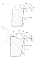
ドリル1に装着されるインサート3の詳細について説明する。図4は、本実施形態のインサートを示す平面図である。図5は、図4のインサートを(a)矢印A側から見た側面図であり、(b)矢印B側から見た側面図である。図6は、図4のインサートについて(a)I−I線の断面を示す拡大図であり、(b)II−II線の断面を示す拡大図、図7は、図6のインサートの断面について(a)I−I線の断面の切刃(外刃)周辺の要部拡大図であり、(b)II−II線の断面の切刃(内刃)周辺の要部拡大図である。 The details of the insert 3 attached to the drill 1 will be described. FIG. 4 is a plan view showing the insert of this embodiment. 5 is a side view of the insert of FIG. 4 as viewed from the arrow A side, and (b) is a side view as viewed from the arrow B side. 6 is an enlarged view showing a cross section taken along line I-I of the insert shown in FIG. 4, (b) an enlarged view showing a cross section taken along line II-II, and FIG. 7 is a cross section of the insert shown in FIG. (A) It is a principal part enlarged view of the cutting blade (outer blade) periphery of the cross section of II line, (b) It is a principal part enlarged view of the cutting blade (inner blade) periphery of the cross section of II-II line.
図4〜7に示す実施形態にかかるインサート3は、上面視が略多角形の板状をなし、上面11の中央部には貫通穴14が形成されている。また、インサート3は、図7に示すように、基体15の表面に被覆層16が被着形成されており、インサート3の上面11と側面12との交差稜辺部18には互いに隣接して内刃5および外刃6が形成されている。
The insert 3 according to the embodiment shown in FIGS. 4 to 7 has a plate shape that is substantially polygonal when viewed from above, and a
そして、図6、7に示すように、外刃6は、外刃逃げ角β2(外刃逃げ面29(側面12)と下面17に垂直な線L1とがなす角度)が正であり、上面11と側面12との交差稜線部18に続く側面12側に下面(着座面)17に対して垂直のストレート20が形成されている。そして、外刃6からストレート20にかけての被覆層16の膜厚が4〜15μmであり、かつ外刃逃げ面29における被覆層16の膜厚よりも厚い構成となっている。かかる構成によって、被覆層16の膜厚が4〜15μmと厚いにも関わらずストレート20の存在によって被覆層16の耐欠損性が高いものである。
As shown in FIGS. 6 and 7, the
また、内刃5も、内刃逃げ角β1(内刃逃げ面23(側面12)と下面17に垂直な線L1とがなす角度)が正であり、上面11と側面12との交差稜線部18に続く側面12側に下面(着座面)17に対して垂直のストレート19が形成されているが、切削加工時に回転軸中心(線O)に近い内刃5は切削速度が小さくて摩擦抵抗が大きいので、内刃5からストレート19にかけての被覆層16の膜厚は、外刃6側のストレート20の被覆層16の膜厚よりも薄いことが重要である。
The
このとき、内刃5におけるストレート19に成膜される被覆層16の膜厚tsiは外刃6からストレート20にかけての被覆層16の膜厚tsoに対して、tsi/tsoの比が0.5〜0.9の範囲内であることが、より耐欠損性を向上させ、かつ、内刃として十分な耐摩耗性を維持することができるため望ましい。ここで、tsi/tsoの比が0.5以上であれば高い耐摩耗性を得ることができる。また、tsi/tsoの比が0.9以下であれば被覆層の剥離や切刃のチッピングを抑え、耐欠損性を向上させることができる。なお、被覆層16の望ましい厚みは耐摩耗性と耐欠損性の点で、外刃6のストレートにおける被覆層16の厚みtsoが4.5〜9μmであり、内刃5の被覆層16の厚みtsiが4〜8μmである。
At this time, the film thickness t si of the
ここで、内刃5のストレート19の長さを外刃6のストレート20の長さよりも長くすることによって、欠損しやすい内刃5の耐欠損性を高めることができる。また、内刃5のストレート19の長さを外刃6のストレート20の長さよりも長くすると、外刃6の先端形状はストレート20が形成されているものの内刃5に比べて若干鋭利な切刃形状となっている。そのために、内刃5のストレート19における被覆層16の厚みが外刃6のストレート20における被覆層16の厚みよりも薄くなるので、欠損しやすい内刃5の耐欠損性をさらに高めることができる。
Here, by making the length of the straight 19 of the
このとき、上記構成の外刃6において、ストレート20における被覆層の厚みをts、外刃逃げ面29における被覆層16の厚みをtfとしたときに、その比率であるts/tfが1.2〜2であることが、外刃6における耐欠損性をさほど低下させずに耐摩耗性の向上ができる点で望ましい。なお、外刃逃げ面29においては時折衝突する切屑によって被覆層16が剥離しないように被覆層16の厚みが薄いほうがよい。また、すくい面(内刃すくい面22、外刃すくい面28)から交差稜線部18(内刃5、外刃6)を経由して逃げ面(内刃逃げ面23、外刃逃げ面29)に至る領域において、被覆層16の厚みが急激に変化する特異点が存在することなく徐変することが望ましい。
At this time, in the
さらに、外刃6のストレート20の長さをLiとすると、Li=0.01mm〜0.095mmであることが、外刃6の切れ味を高めることができるとともに、外刃6における被覆層16の耐摩耗性を向上できる点で望ましい。
Furthermore, when the length of the straight 20 of the
また、インサート3が複雑な形状であっても、内刃5のストレート19の長さLiおよび外刃6のストレート20の長さLoが切刃稜線部18の全周にわたって0.005mm以内のばらつきで均一であるために、内刃5の切刃強度、および外刃6での被覆層16の耐摩耗性のバラツキを小さくできる。
Even if the insert 3 has a complicated shape, the length Li of the straight 19 of the
さらに、内刃5と外刃6との両方を具備するインサート3を2つ以上用いて、一方は内刃5が工具本体2の先端に突出するように装着され、他方は外刃6が工具本体2の外周から先端にわたって工具本体2から突出するように装着された構成、すなわち1つのインサート3内に内刃5と外刃6との両方が形成されたインサート形状においても、後述する金型に工夫を加えることによって、インサート3内に上記内刃5のストレート19と外刃6のストレート20の構成を実現することができる。
Furthermore, two or more inserts 3 having both the
なお、図6(a)に示すように、内刃5は、インサート3の上面11(内刃すくい面22)と側面12(内刃逃げ面23)との交差稜線部18に形成されているが、図6(a)に示すように、この内刃5から順に0.05〜0.15mmの内刃ランド21と、内刃すくい角α1(内刃すくい面22の仮想延長線L2と、下面17に平行な線L3とがなす角度)が5°〜25°で下向きに傾斜している内刃すくい面22とが続いて形成されている。また、内刃5の側面12には内刃逃げ面23が形成されている。
As shown in FIG. 6A, the
一方、外刃6は、図6(b)に示すように、上面11(外刃すくい面28)と側面12(外刃逃げ面29)との交差稜線部18に形成されており、図4に示すように、その一端側に上面視でインサート3から外方に突出した突出部25を有している。そして、図6(b)に示すように、この外刃6から順に、0.05〜0.15mmの外刃ランド26と、幅1.2〜2mmで深さ0.03〜0.15mmの外刃ブレーカ溝27と、外刃陸部24とが続いて形成されている。また、外刃6の側面12には外刃逃げ面29が形成されている。
On the other hand, as shown in FIG. 6 (b), the
外刃ブレーカ溝27は、すくい角α2(外刃すくい面28の仮想延長線L4と、下面17に平行な線L3とがなす角度)が5°〜25°の下向きに傾斜した外刃すくい面28と、この外刃すくい面28からインサート3の中央側(貫通穴14側)に向かって立ち上がり角γ(外刃立ち上がり面30の仮想延長線L5と、下面17に平行な線L3とのなす角度)20°〜45°で立ち上がた外刃立ち上がり面30とからなる。
The outer
また、インサート3を構成する基体15は、例えば超硬合金、サーメット、セラミックス、ダイヤモンド、cBN等の硬質焼結体からなる。 The base 15 constituting the insert 3 is made of a hard sintered body such as cemented carbide, cermet, ceramics, diamond, or cBN.
また、上記ストレート19、20を形成する方法について、図8に示すインサート3の成形体を作製するための成形用金型におけるダイスの一例を基に説明する。
The method of forming the
本発明においては、成形体を作製するための顆粒として弾性の高いバインダを添加する。これによって、プレス成形時に成形体がスプリングバックによって膨張して切刃となるエッジ部が金型の壁面にこすれて摩耗する形態とする。 In the present invention, a highly elastic binder is added as a granule for producing a molded body. Thus, at the time of press molding, the molded body is expanded by the spring back, and the edge portion that becomes the cutting edge is rubbed against the wall surface of the mold and worn.
また、外刃6のストレート20の長さLoを内刃5のストレート19の長さLiよりも小さくする方法について図8を基に説明する。図8にはインサート用の成形体を作製するためのプレス成形用金型におけるダイスの一例についての(a)概略平面図、(b)(a)のA−A断面(外刃)の要部拡大断面図を示す。図9には図8のプレス成形用金型を用いて(a)成形体を加圧している状態、(b)プレス成形体を取り出す状態を示す模式図を示している。
A method for making the length Lo of the straight 20 of the
図8、9に示すように、プレス成形用金型38は、内側の外刃側(A−A断面側)に、逃げ角β2(>0)のインサート3を成形するために上部に向かって幅が広がる成形体部31と、成形体部31の外刃6の上端面Xの直上に位置して垂直壁面部32の高さt2との比t2/成形体部31の高さt1=0.03〜0.35の垂直壁面部32と、垂直壁面部32の直上に位置して垂直壁面部32よりも角度θ(θ>β)で幅(w)が広がる逃がし部33とを具備する形状の空洞34が形成されたダイス35と、棒状をなす上パンチ36および下パンチ37の一対のパンチとからなる。
As shown in FIGS. 8 and 9, the press-
このプレス成形用金型38を用いて成形すると、図9に示すように、成形体39をダイス35から取り出す際に外刃6側においては、成形体39がスプリングバックによって膨張しても垂直壁面部32の長さ分だけしか成形体39の上面側側面端部40が干渉しないので、成形体39の上面側側面端部40の形状が潰れることなく擦れ摩耗部が小さくなる。また、一対のパンチ36、37で加圧する際に成形体部31の上面から上横部に押し出された粉末は、通常上パンチ36とダイス35との間に挟まれてバリを生じさせてしまうこともあるが、本発明によれば、この押し出された粉末が逃がし部33に抜けてゆくのでさほど高い圧力で加圧されることもなくて発生するバリを極薄くかつ低密度なものとすることができる。そのため、成形後にエアを吹き付けるようなわずかな力で容易にバリ取りをすることができる。その結果、成形体39の外刃6側のストレート20を小さくして鋭利なエッジとすることができる。なお、金型38の内刃5の形成部側には逃がし部33を設けずに、垂直壁面部32が前記高さt2よりも高くなる、もしくはそのまま金型38の上面まで続く形状とすることにより、成形体39をダイス35の上部に押し上げて取り出す際に内刃5、外刃6の部分がダイス35の内壁面に干渉して成形体39の側面12の交差稜線部18の直下に擦れ摩耗によるストレート19、20を形成できる。
When this press molding die 38 is used for molding, as shown in FIG. 9, when the molded
また、焼成後の基体15に被覆層16の成膜方法としてはイオンプレーティング法等の物理蒸着(PVD)法が好適に適応可能である。詳細な成膜方法の一例について、アークイオンプレーティング成膜装置(以下、AIP装置と略す。)50の模式図である図10を参照して説明する。
Moreover, physical vapor deposition (PVD) methods, such as an ion plating method, can be applied suitably as a film-forming method of the
図10のAIP装置50は、真空チャンバ51の中にN2やAr等のガスをガス導入口52から導入し、カソード電極53とアノード電極54とを配置して、両者間に高電圧を印加してプラズマを発生させ、このプラズマによってターゲット55から所望の金属あるいはセラミックスを蒸発させるとともにイオン化させて高エネルギー状態とし、このイオン化した金属を試料(基体15)の表面に付着させて、基体15の表面に被覆層16を被覆する構造となっている。また、図10によれば、基体15は試料支持冶具56に設けられた複数の試料支持部58それぞれにすくい面がターゲット55に対向するように載置されてタワー57が複数(図10では試料支持冶具56が8セット、タワー57が2セット図示されている。)配置された構成となっている。また、タワー57および試料支持冶具56はそれぞれ回転しており、各試料が順にターゲット55に対向して被覆層の厚みは均一となるように配慮されている。この構成によって、各試料の切刃全周の厚みばらつきを小さくできるので、全体の厚みが厚くなっても部分的に欠損しやすい部分ができにくい。
The AIP device 50 of FIG. 10 introduces a gas such as N 2 or Ar into the vacuum chamber 51 from the
さらに、図10によれば、基体15を加熱するためのヒータ59と、ガスを系外に排出するためのガス排出口60と、基体15にバイアス電圧を印加するためのバイアス電源61が配置されている。そして、ターゲット55を用いて、アーク放電やグロー放電などにより金属源を蒸発させイオン化すると同時に、窒素源の窒素(N2)ガスや炭素源のメタン(CH4)/アセチレン(C2H2)ガスと反応させることにより、基体15の表面に被覆層7が堆積する。
Further, according to FIG. 10, a heater 59 for heating the
なお、ターゲット55としては、例えば、金属チタン(Ti)、金属アルミニウム(Al)、金属M(ただし、MはTiを除く周期表第4、5、6族元素、希土類元素およびSiから選ばれる1種以上)をそれぞれ独立に含有する金属ターゲット、これらを複合化した合金ターゲット、これらの化合物粉末または焼結体からなる混合物ターゲットを用いることができる。
The
また、プラズマを発生するためにはアーク放電やグロー放電などを用い、導入ガスとしては窒素源の窒素(N2)ガスや炭素源のメタン(CH4)/アセチレン(C2H2)ガスを用いることができる。そして、窒素(N2)ガスやアルゴン(Ar)ガスを流した状態で成膜する。また、成膜時のバイアス電圧は被覆層16の内部応力を小さくするために30〜125Vに設定することが望ましい。
Further, arc discharge or glow discharge is used to generate plasma, and nitrogen (N 2 ) gas as a nitrogen source or methane (CH 4 ) / acetylene (C 2 H 2 ) gas as a carbon source is used as an introduction gas. Can be used. Then, a film is formed in a state where nitrogen (N 2 ) gas or argon (Ar) gas is supplied. Further, it is desirable that the bias voltage during film formation is set to 30 to 125 V in order to reduce the internal stress of the
WC粉末、Co粉末、Cr3C2粉末およびTaC粉末を混合し、これにバインダとしてパラフィンを添加、造粒して平均粒径100μmの造粒粉末を調整した。次に、所定部分が図7に示す断面の形状で、京セラ製スローアウェイドリルの型番ZCMT06T204、インサートの厚み(成形体部の高さ)t1=3.79mm、内刃逃げ角β1=7°、外刃逃げ角β2=13°のインサートを成形できる図8のダイスと、これに嵌め込まれる一対のパンチを準備し、これに図9のように、上記造粒粉末を充填してプレス成形し、エアブラシによってバリ取り加工を施し、逃げ角が正のポジチップ形状の成形体を得た。この成形体を脱バインダ処理して真空焼成して研削加工およびホーニング加工を行った後、図10の状態で試料を成膜装置内に載置して、窒素(N2)ガスをチャンバ内に導入してバイアス電圧50Vの条件でPVD法によって表1に示す厚みのTiAlN被覆層を成膜してインサートを作製した。なお、試料No.10、11についてはTiAlN被覆層を成膜した後、被覆層の表面をブラシ研磨して被覆層の厚みを調整した。 WC powder, Co powder, Cr 3 C 2 powder and TaC powder were mixed, and paraffin was added as a binder and granulated to prepare a granulated powder having an average particle size of 100 μm. Next, the predetermined portion has the cross-sectional shape shown in FIG. 7, the Kyocera throwaway drill model number ZCMT06T204, the thickness of the insert (the height of the molded body) t 1 = 3.79 mm, the inner blade clearance angle β1 = 7 °. 8 is prepared, and a pair of punches fitted into the die of FIG. 8 capable of forming an insert having an outer blade clearance angle β2 = 13 °, and a pair of punches fitted therein are filled and press-molded by filling the granulated powder as shown in FIG. Then, deburring was performed with an air brush, and a positive chip-shaped molded body having a positive clearance angle was obtained. After the binder is removed and vacuum fired to perform grinding and honing, the sample is placed in the film forming apparatus in the state shown in FIG. 10, and nitrogen (N 2 ) gas is introduced into the chamber. Then, a TiAlN coating layer having a thickness shown in Table 1 was formed by PVD under the condition of a bias voltage of 50 V to produce an insert. Sample No. For Nos. 10 and 11, after forming a TiAlN coating layer, the surface of the coating layer was brushed to adjust the thickness of the coating layer.
得られたインサートの切刃部を投影機にて観察し、内刃と外刃における逃げ面の切刃直下にストレートが形成されたか否か、およびその長さを測定した。測定に際しては、ストレート長さの測定は形状測定器を用いて行った。より具体的には、インサートの側面を形状測定器で観察して写真のコントラストからストレート長さを測定した。なお、測定に際して切刃にホーニングが形成されている場合には、ホーニング加工された部分の下限を基準点として逃げ面側に伸びるストレート長さを測定した。また、この方法でストレート長さがわからないときには、交差稜線部を含む断面でインサートを切断し、その断面を顕微鏡にて観察してストレート長さを計測した。また、試料の断面観察を行って、ストレート、逃げ面それぞれにおける被覆層の厚みを測定した。なお、逃げ面の被覆層の厚みは逃げ面の中間における被覆層の厚みを測定した。結果は表1に示した。また、内刃および外刃にバリの残存はなかった。なお、試料No.6は参考試料である。
The cutting edge portion of the obtained insert was observed with a projector, and whether or not a straight was formed immediately below the cutting edges of the flank surfaces of the inner blade and the outer blade and the length thereof were measured. In measurement, the straight length was measured using a shape measuring instrument. More specifically, the side length of the insert was observed with a shape measuring instrument, and the straight length was measured from the contrast of the photograph. When the honing was formed on the cutting edge at the time of measurement, the straight length extending toward the flank face was measured with the lower limit of the honed portion as the reference point. Further, when the straight length was not known by this method, the insert was cut along a cross section including the intersecting ridge line portion, and the cross section was observed with a microscope to measure the straight length. Moreover, the cross-section observation of the sample was performed and the thickness of the coating layer in each of a straight and a flank was measured. The thickness of the coating layer on the flank was measured by measuring the thickness of the coating layer in the middle of the flank. The results are shown in Table 1. Further, no burrs remained on the inner blade and the outer blade. Sample No. 6 is a reference sample.

そして、このインサートを図1の工具本体(京セラ製スローアウェイドリルホルダS25−DRZ1734−06)に装着して以下の切削試験を行い、切削性能を評価した。
切削方法:穴あけ(ドリル加工)
被削材 :SCM440H
切削速度:150m/分
送り :0.1mm/刃
切り込み:穴径20mm、穴深さ20mm
切削状態:湿式
評価方法:800穴加工を上限として切削を行い、内刃(あるいは外刃)に欠損が生じるまでの加工数を記録した。さらに、外刃については400穴加工後における逃げ面摩耗量を計測して耐摩耗性の比較も行った。なお、摩耗量の測定の際にはホーニング長さを摩耗量に含めないようにして測定した。結果は表2に示した。
Then, this insert was mounted on the tool body (Kyocera throwaway drill holder S25-DRZ1734-06) shown in FIG. 1 and the following cutting test was performed to evaluate the cutting performance.
Cutting method: Drilling
Work material: SCM440H
Cutting speed: 150 m / minute feed: 0.1 mm / blade cutting:
Cutting state: wet evaluation method: Cutting was performed with an upper limit of 800 hole machining, and the number of machining until the inner blade (or outer blade) was damaged was recorded. Further, for the outer cutter, the amount of flank wear after 400 holes was machined was measured to compare the wear resistance. In measuring the wear amount, the honing length was not included in the wear amount. The results are shown in Table 2.
表1、2の結果から明らかなように、外刃および内刃におけるストレートの長さが0.005mm未満とストレートが形成されていない試料No.8では、内刃が早期に欠損し、外刃における摩耗も大きいものであった。また、内刃および外刃のストレートにおける被覆層の厚みが逃げ面における被覆層の厚みより小さくした試料No.10では、耐摩耗性が悪いものであった。さらに、内刃および外刃のストレートにおける被覆層の厚みが逃げ面における被覆層の厚み同じ試料No.9では、外刃における摩耗の進行が速くて、内刃においてはチッピングも発生した。 As is clear from the results in Tables 1 and 2, the straight lengths of the outer blade and the inner blade are less than 0.005 mm, and no sample is formed. In No. 8, the inner blade was lost early, and the wear on the outer blade was large. In addition, the sample No. 1 in which the thickness of the coating layer on the straight of the inner blade and the outer blade was smaller than the thickness of the coating layer on the flank face. In No. 10, the wear resistance was poor. Furthermore, the sample Nos. 1 and 2 have the same coating layer thickness on the flank as the coating layer thickness on the inner blade and outer blade straight. In No. 9, the progress of wear on the outer blade was fast, and chipping occurred on the inner blade.
これに対して、本発明に従い、内刃と外刃にストレートを形成して被覆層を4〜15μmの厚みとするとともに、ストレートにおける被覆層の厚みを逃げ面における被覆層の厚みよりも厚くした試料No.1〜7では、いずれも耐欠損性および耐摩耗性に優れたものであった。 On the other hand, according to the present invention, a straight is formed on the inner blade and the outer blade so that the coating layer has a thickness of 4 to 15 μm, and the thickness of the coating layer on the straight is made larger than the thickness of the coating layer on the flank. Sample No. In Nos. 1 to 7, all were excellent in fracture resistance and wear resistance.
1 ドリル
2 工具本体
3 スローアウェイインサート(インサート)
3a 一方のインサート
3b 他方のインサート
4 ネジ
5 内刃
6 外刃
8 シャンク部
9 切屑排出溝
10 インサートポケット
10a 内側のインサートポケット
10b 外側のインサートポケット
11 上面
12 側面
14 貫通穴
15 基体
16 被覆層
17 下面(着座面)
18 交差稜線部
19、20 ストレート
21 内刃ランド
22 内刃すくい面
23 内刃逃げ面
24 外刃陸部
25 突出部
26 外刃ランド
27 外刃ブレーカ溝
28 外刃すくい面
29 外刃逃げ面
30 外刃立ち上がり面
31 成形体部
32 垂直壁面部
33 逃がし部
34 内側の空洞
35 ダイス
36 上パンチ
37 下パンチ
38 プレス成形用金型
39 成形体
40 上面側側面端部
50 アークイオンプレーティング成膜装置(AIP装置)
51 真空チャンバ
52 ガス導入口
53 カソード電極
54 アノード電極
55 ターゲット
56 試料支持冶具
57 タワー
58 試料支持部
59 ヒータ
60 ガス排出口
61 バイアス電源
O ドリルの回転軸
Li 内刃のストレートの長さ
Lo 外刃のストレート長さ
L1 下面(着座面)に垂直な線
L2 内刃すくい面の仮想延長線
L3 下面(着座面)に平行な線
L4 外刃すくい面の仮想延長線
L5 外刃立ち上がり面の仮想延長線
α1 内刃すくい角
α2 外刃すくい角
β1 内刃逃げ角
β2 外刃逃げ角
γ 立ち上がり角
t1 成形体部の高さ
t2 垂直壁面部の高さ
1
3a One
18 Crossed
51
Claims (3)
Priority Applications (1)
| Application Number | Priority Date | Filing Date | Title |
|---|---|---|---|
| JP2008131584A JP5219618B2 (en) | 2008-05-20 | 2008-05-20 | Cutting tools |
Applications Claiming Priority (1)
| Application Number | Priority Date | Filing Date | Title |
|---|---|---|---|
| JP2008131584A JP5219618B2 (en) | 2008-05-20 | 2008-05-20 | Cutting tools |
Publications (2)
| Publication Number | Publication Date |
|---|---|
| JP2009279672A JP2009279672A (en) | 2009-12-03 |
| JP5219618B2 true JP5219618B2 (en) | 2013-06-26 |
Family
ID=41450681
Family Applications (1)
| Application Number | Title | Priority Date | Filing Date |
|---|---|---|---|
| JP2008131584A Active JP5219618B2 (en) | 2008-05-20 | 2008-05-20 | Cutting tools |
Country Status (1)
| Country | Link |
|---|---|
| JP (1) | JP5219618B2 (en) |
Families Citing this family (2)
| Publication number | Priority date | Publication date | Assignee | Title |
|---|---|---|---|---|
| DE102006044605A1 (en) * | 2006-09-19 | 2008-03-27 | Komet Group Holding Gmbh | Indexable insert and use of the indexable insert in a solid drill |
| JP6287197B2 (en) * | 2013-12-26 | 2018-03-07 | 三菱マテリアル株式会社 | Drill inserts and replaceable drill tips |
Family Cites Families (2)
| Publication number | Priority date | Publication date | Assignee | Title |
|---|---|---|---|---|
| JPH1068076A (en) * | 1996-08-26 | 1998-03-10 | Mitsubishi Materials Corp | Production of cutting tool made of surface-coated cemented carbide excellent in chipping resistance |
| JP4794163B2 (en) * | 2004-12-24 | 2011-10-19 | 京セラ株式会社 | Method for manufacturing throw-away tip |
-
2008
- 2008-05-20 JP JP2008131584A patent/JP5219618B2/en active Active
Also Published As
| Publication number | Publication date |
|---|---|
| JP2009279672A (en) | 2009-12-03 |
Similar Documents
| Publication | Publication Date | Title |
|---|---|---|
| JP5116777B2 (en) | Cutting tools | |
| US11027338B2 (en) | Cutting insert, cutting tool, and method for manufacturing machined product | |
| JP5339984B2 (en) | Cutting tools | |
| JP5404232B2 (en) | Cutting tools | |
| JP5517577B2 (en) | Cutting tool for grooving | |
| JP4991244B2 (en) | Surface coated cutting tool | |
| JP2009285760A (en) | Cutware | |
| JP5219618B2 (en) | Cutting tools | |
| JP3928481B2 (en) | Surface-coated cemented carbide cutting tool with excellent wear resistance under high-speed heavy cutting conditions. | |
| JP3928480B2 (en) | Surface coated cemented carbide cutting tool with excellent wear resistance with hard coating layer in high speed cutting | |
| JP5230374B2 (en) | Throw-away insert for grooving | |
| JP5241538B2 (en) | Cutting tools | |
| JP5294648B2 (en) | Rotating tool | |
| JP5495735B2 (en) | Cutting tools | |
| JP3969260B2 (en) | Surface coated cemented carbide cutting tool with excellent chipping resistance with hard coating layer under high speed heavy cutting conditions | |
| JP5334704B2 (en) | Cutting tools | |
| JP2006181653A (en) | Surface coated thermet-made cutting tool having hard coating layer exhibiting excellent chipping resistance in intermittent heavy cutting | |
| JP2003175405A (en) | Surface-coated cemented-carbide cutting tool having hard coating layer exhibiting excellent heat resistance | |
| JP4895586B2 (en) | Surface coated cutting tool | |
| JP3928452B2 (en) | Surface coated cemented carbide cutting tool with excellent chipping resistance with hard coating layer under heavy cutting conditions | |
| JP5094293B2 (en) | Cutting tools | |
| JP4066341B2 (en) | Surface-coated cemented carbide cutting tool with a hard coating layer with excellent adhesion and wear resistance | |
| JP3928459B2 (en) | Cutting tool made of surface-coated cemented carbide that provides excellent wear resistance with a hard coating layer in high-speed cutting of difficult-to-cut materials | |
| JP3928497B2 (en) | Surface coated cemented carbide cutting tool with excellent chipping resistance with hard coating layer under high speed heavy cutting conditions | |
| JP3972294B2 (en) | Surface coated cemented carbide cutting tool with excellent wear resistance with hard coating layer in high speed cutting |
Legal Events
| Date | Code | Title | Description |
|---|---|---|---|
| A621 | Written request for application examination |
Free format text: JAPANESE INTERMEDIATE CODE: A621 Effective date: 20101215 |
|
| A977 | Report on retrieval |
Free format text: JAPANESE INTERMEDIATE CODE: A971007 Effective date: 20120924 |
|
| A131 | Notification of reasons for refusal |
Free format text: JAPANESE INTERMEDIATE CODE: A131 Effective date: 20121002 |
|
| A521 | Written amendment |
Free format text: JAPANESE INTERMEDIATE CODE: A523 Effective date: 20121130 |
|
| TRDD | Decision of grant or rejection written | ||
| A01 | Written decision to grant a patent or to grant a registration (utility model) |
Free format text: JAPANESE INTERMEDIATE CODE: A01 Effective date: 20130205 |
|
| A61 | First payment of annual fees (during grant procedure) |
Free format text: JAPANESE INTERMEDIATE CODE: A61 Effective date: 20130305 |
|
| FPAY | Renewal fee payment (event date is renewal date of database) |
Free format text: PAYMENT UNTIL: 20160315 Year of fee payment: 3 |
|
| R150 | Certificate of patent or registration of utility model |
Ref document number: 5219618 Country of ref document: JP Free format text: JAPANESE INTERMEDIATE CODE: R150 Free format text: JAPANESE INTERMEDIATE CODE: R150 |