JP5217492B2 - Blind shutter control device - Google Patents
Blind shutter control device Download PDFInfo
- Publication number
- JP5217492B2 JP5217492B2 JP2008043807A JP2008043807A JP5217492B2 JP 5217492 B2 JP5217492 B2 JP 5217492B2 JP 2008043807 A JP2008043807 A JP 2008043807A JP 2008043807 A JP2008043807 A JP 2008043807A JP 5217492 B2 JP5217492 B2 JP 5217492B2
- Authority
- JP
- Japan
- Prior art keywords
- blind
- slat
- opening
- shutter
- registration
- Prior art date
- Legal status (The legal status is an assumption and is not a legal conclusion. Google has not performed a legal analysis and makes no representation as to the accuracy of the status listed.)
- Active
Links
- 238000001514 detection method Methods 0.000 claims description 27
- 238000002360 preparation method Methods 0.000 claims description 15
- 238000003860 storage Methods 0.000 claims description 11
- 230000008859 change Effects 0.000 claims description 2
- 238000004804 winding Methods 0.000 description 15
- 238000000034 method Methods 0.000 description 9
- 230000008569 process Effects 0.000 description 9
- 230000006870 function Effects 0.000 description 6
- 238000003825 pressing Methods 0.000 description 4
- 238000010586 diagram Methods 0.000 description 3
- 230000000694 effects Effects 0.000 description 3
- 230000002265 prevention Effects 0.000 description 3
- XLYOFNOQVPJJNP-UHFFFAOYSA-N water Substances O XLYOFNOQVPJJNP-UHFFFAOYSA-N 0.000 description 3
- 238000005282 brightening Methods 0.000 description 2
- 230000020169 heat generation Effects 0.000 description 2
- 238000009434 installation Methods 0.000 description 2
- 230000008054 signal transmission Effects 0.000 description 2
- 230000009471 action Effects 0.000 description 1
- 230000007246 mechanism Effects 0.000 description 1
- 230000000630 rising effect Effects 0.000 description 1
Images


Description
本発明は、建物などの構造物の開口部に取り付けられ、スラットをブラインドとして開閉させることができるブラインドシャッター制御装置に関する。 The present invention relates to a blind shutter control device that is attached to an opening of a structure such as a building and can open and close a slat as a blind.
従来、特許文献1には、使用者の所望するブラインド開度にスラットが開放されるまでスラットを回動させる操作(例えば操作パネルの開スイッチをずっと押すあるいは開スイッチを必要回数押すなど)の動作をし続ける電動シャッターが示されている。また、特許文献1には、スラットをブラインドとして回動させることができるシャッターの開閉方向の位置が決められている電動シャッターの場合に、ワンタッチの操作で電動シャッターが決められた位置まで開閉方向に可動させることができる準備動作が開示されている。
上記した特許文献1では、スラットをブラインドとして全開放する場合など、開スイッチを押し続けるあるいは何度も開スイッチを押す必要がある。また、準備動作はワンタッチでスラットがブラインドとして開放できる位置までシャッターが開閉するので便利であるが、シャッターの準備動作後、スラットをブラインドとして回動させる操作を別にしなければスラットを開放させることができない。 In the above-mentioned Patent Document 1, it is necessary to keep pressing the open switch or press the open switch many times, such as when the slat is fully opened as a blind. The preparatory operation is convenient because the shutter opens and closes to a position where the slat can be opened as a blind with a single touch, but after the preparatory operation of the shutter, the slat can be opened unless the slat is rotated as a blind. Can not.
本発明は、上記課題に鑑みてなされたもので、スラットをブラインドとして開放するための操作負担および準備動作のための操作の手間を軽減させることができるブラインドシャッター制御装置を提供することを解決すべき課題とする。 The present invention has been made in view of the above problems, and solves the problem of providing a blind shutter control device capable of reducing an operation burden for opening a slat as a blind and an operation for a preparation operation. It should be a challenge.
本発明のブラインドシャッター制御装置は、シャッターを構成するスラットをブラインドとして回動させるブラインド駆動部と、前記スラットのブラインド開度を変更するための信号が出力されるブラインド開放信号出力手段と、前記ブラインド駆動部を駆動させる制御手段と、を有するブラインドシャッター制御装置において、前記スラットの前記ブラインド開度を検出するブラインド開度検出手段を有し、前記制御手段は、登録された前記ブラインド開度である1または複数のブラインド登録位置に前記ブラインド開放信号出力手段の出力信号に基づいて前記スラットを回動させるブラインド登録位置回動手段と、前記ブラインド開放信号出力手段の出力信号に基づいた前記ブラインド開度に前記スラットを開閉回動する通常モードと、を有し、前記ブラインド登録位置回動手段は、前記ブラインド登録位置に前記スラットを回動させるために前記ブラインド開放信号出力手段が出力する信号量が、前記通常モードで前記ブラインド登録位置に前記スラットを回動させるために前記ブラインド開放信号出力手段が出力する信号量より少なく、前記制御手段は、前記ブラインド開度検出手段で取得した前記スラットの前記ブラインド開度が閉位置の場合に前記ブラインド登録位置回動手段を実行し、前記ブラインド開度検出手段で取得した前記スラットの前記ブラインド開度が前記閉位置以外の場合に前記通常モードを実行することを特徴とする。 A blind shutter control device according to the present invention includes a blind drive unit that rotates a slat constituting a shutter as a blind, a blind opening signal output unit that outputs a signal for changing the blind opening of the slat, and the blind And a blind shutter control device having a blind opening detection means for detecting the blind opening of the slat, wherein the control means is the registered blind opening. Blind registration position rotating means for rotating the slat to one or more blind registration positions based on the output signal of the blind opening signal output means, and the blind opening based on the output signal of the blind opening signal output means A normal mode for opening and closing the slats, The blind registration position rotation means has a signal amount output by the blind opening signal output means for rotating the slat to the blind registration position, so that the slat is at the blind registration position in the normal mode. When the blind opening of the slat acquired by the blind opening detection means is in the closed position, the control means is less than the amount of signal output by the blind opening signal output means for rotation. The rotation mode is executed, and the normal mode is executed when the blind opening degree of the slat acquired by the blind opening degree detection means is other than the closed position .
本発明のブラインドシャッター制御装置は、ブラインド登録位置回動手段により、ブラインド開放信号出力手段から出力される信号に基づいて、登録されたブラインド開度であるブラインド登録位置にスラットを回動することができる。ブラインド登録位置は、予め設定登録されたスラットのブラインド開度である。ブラインド開放信号出力手段から信号が出力されると、スラットが設定登録されたブラインド登録位置に回動するので、ブラインド開度を調節しなくても所定のブラインド開度にすることができる。 In the blind shutter control device of the present invention, the blind registration position rotation means can rotate the slat to the blind registration position which is the registered blind opening based on the signal output from the blind opening signal output means. it can. The blind registration position is a blind opening degree of a slat set and registered in advance. When a signal is output from the blind opening signal output means, the slat rotates to the registered blind registration position, so that the predetermined blind opening can be achieved without adjusting the blind opening.
ブラインド登録位置回動手段は、通常モードでスラットを回動する場合の信号量より少ない信号量で、ブラインド登録位置までスラットを回動させることができる。よって、ブラインド開放信号出力手段から制御部における信号の伝達経路を縮小化あるいは簡素化することができる。
スラットがブラインドとして閉じている場合に、スラットをブラインドとして開放させる操作が入力手段に入力されると、ブラインド登録位置回動手段によってスラットがブラインド登録位置まで回動する。そして、スラットがブラインドとして開放している場合には、スラットをブラインドとして開放させる操作が入力手段に入力されると、通常モードのブラインド開度でスラットが開閉する。これにより、スラットが閉じている状態でスラットをブラインドとして開放しようと使用者が入力手段に操作を入力すれば、ブラインド登録位置までスラットが回動するので、入力操作をし続けることなくある程度までスラットが開放される。つまり、使用者の入力操作を軽減できる。通常モードは、スラットがブラインドとして所望のブラインド開度になるまで入力手段の入力に基づき、スラットを回動させる。この通常モードは、入力手段の入力がされ続ける場合にスラットを入力された時間に応じて回動させるものでも、一入力で一定のブラインド開度(<ブラインド登録位置のブラインド開度)だけ回動させるものでも良い。
The blind registration position rotation means can rotate the slat to the blind registration position with a signal amount smaller than the signal amount when the slat is rotated in the normal mode. Therefore, the signal transmission path from the blind opening signal output means to the control unit can be reduced or simplified.
When an operation for opening the slat as a blind is input to the input means when the slat is closed as a blind, the slat is rotated to the blind registration position by the blind registration position rotation means. When the slat is opened as a blind, when an operation for opening the slat as a blind is input to the input means, the slat is opened and closed at the blind opening in the normal mode. As a result, if the user inputs an operation to the input means to open the slat as a blind while the slat is closed, the slat rotates to the blind registration position. Is released. That is, user input operations can be reduced. In the normal mode, the slat is rotated based on the input of the input means until the slat is blinded and reaches a desired blind opening. In this normal mode, even if the slat is rotated according to the input time when the input of the input means is continued, it is rotated by a certain blind opening (<blind opening of the blind registration position) with one input. It may be a thing to let
本発明のブラインドシャッター制御装置で用いられる前記制御手段は、前記ブラインド開放信号出力手段は、前記スラットの前記ブラインド開度を変更するための操作が入力される入力手段を有し、前記ブラインド登録位置回動手段は、前記ブラインド登録位置に前記スラットを回動させるために前記入力手段に入力する操作量が、前記通常モードで前記ブラインド登録位置に前記スラットを回動させるために前記入力手段に入力する操作量より少ないことが好ましい。これにより、ブラインド登録位置回動手段は、通常モードでスラットを回動する場合に入力手段へ入力する操作量より少ない操作量で、ブラインド登録位置までスラットを回動させることができる。よって、使用者の操作量が低減できる。また、登録された所定のブラインド開度であるブラインド登録位置にスラットが開放されているので、その後に通常モードで使用者の所望のブラインド開度にスラットを回動させる際の操作量も少なくてすむ。 Said control means used in a blind shutter control device of the present invention, prior Symbol blind opening signal output means includes input means for operation is input to change the blind opening of the slats, the blind registration The position rotation means is configured such that an operation amount input to the input means for rotating the slat to the blind registration position is applied to the input means for rotating the slat to the blind registration position in the normal mode. It is preferable that the operation amount is less than the input amount. Thereby, the blind registration position rotation means can rotate the slat to the blind registration position with an operation amount smaller than the operation amount input to the input means when rotating the slat in the normal mode. Therefore, the operation amount of the user can be reduced. In addition, since the slat is opened at the registered blind position where the predetermined blind opening is registered, the amount of operation when rotating the slat to the desired blind opening of the user in the normal mode after that is small. I'm sorry.
本発明のブラインドシャッター制御装置で用いられる前記ブラインド登録位置回動手段は、前記ブラインド登録位置に前記スラットを回動させるように前記ブラインド駆動部の駆動量が設定されていることが好ましい。 The blind registration position rotating means used in the blind shutter control device of the present invention is preferably configured such that the drive amount of the blind drive unit is set so as to rotate the slat to the blind registration position.
本発明のブラインドシャッター制御装置は、前記シャッターの開閉方向における前記シャッターの位置を検出するシャッター位置検出手段と、前記入力手段に操作が入力され前記シャッター位置検出手段で取得した前記シャッターの位置が目標位置でない場合に、前記シャッターを前記目標位置まで開閉させる準備手段と、を更に有することが好ましい。入力手段への操作の入力は、スラットをブラインドとして回動させるためのものであるが、シャッターがスラットをブラインドとして回動させる適当な位置でない場合は、シャッターを適当な位置である目標位置まで開閉させることができる。これにより、使用者はスラットをブラインドとして回動させるための入力操作を行うだけで、シャッターが目標位置まで自動的に開閉し、その後スラットが回動するので、使用者の入力操作が軽減され、使い勝手が良い。 The blind shutter control device according to the present invention includes a shutter position detecting unit that detects the position of the shutter in the opening and closing direction of the shutter, and the position of the shutter acquired by the shutter position detecting unit when an operation is input to the input unit. It is preferable to further include a preparation unit that opens and closes the shutter to the target position when the position is not a position. The input of the operation to the input means is for rotating the slat as a blind, but when the shutter is not an appropriate position for rotating the slat as a blind, the shutter is opened and closed to a target position which is an appropriate position. Can be made. As a result, the user simply performs an input operation to rotate the slat as a blind, and the shutter automatically opens and closes to the target position, and then the slat rotates to reduce the user's input operation. Convenience is good.
本発明のブラインドシャッター制御装置に用いられる前記準備手段は、前記シャッターの前記目標位置を前記シャッター位置検出手段から取得し記憶するシャッター目標位置記憶手段を有することが好ましい。準備手段は、スラットがブラインドとして回動できるシャッターの位置をシャッター目標位置記憶手段がシャッター位置検出手段から取得することができるので、使用者等が設定する必要がない。よって、使用者等の設定の手間を減らすことができる。 The preparation unit used in the blind shutter control device of the present invention preferably includes a shutter target position storage unit that acquires and stores the target position of the shutter from the shutter position detection unit. The preparation means does not need to be set by the user or the like because the shutter target position storage means can acquire the shutter position from which the slat can rotate as a blind from the shutter position detection means. Therefore, it is possible to reduce the setting time of the user or the like.
本発明のブラインドシャッター制御装置に用いられる前記スラットのブラインドとしての回動領域は、閉位置から直角より大きい前記ブラインド開度の位置まで回動でき、前記ブラインド登録位置の前記ブラインド開度は直角以下であることが好ましい。これにより、本発明のブラインドシャッター制御装置が設置される窓などの開口部の室外側に他者がいた場合などに室内をのぞき見ることができにくい。また、ブラインドが上下方向に開閉回動するタイプの場合では、スラットのブラインド登録位置のブラインド開度が直角以下であれば、雨天時にスラットをブラインドとして開放してもスラットの隙間から雨が入り込むのとスラットに付着した水滴が室内側に流れ込むのとを防止できる。よって、雨垂れ防止などの部材を省略することができ、それに伴うコストも抑えられる。その他に、直射日光の進入も防ぐことができ、いきなり室内が明るくなるのを制御したりすることもできる。 The rotation area of the slat as a blind used in the blind shutter control device of the present invention can be rotated from a closed position to a position of the blind opening larger than a right angle, and the blind opening at the blind registration position is less than a right angle. It is preferable that Accordingly, it is difficult to look into the room when there is another person outside the opening of an opening such as a window where the blind shutter control device of the present invention is installed. In addition, in the case of a type in which the blind is opened and closed in the vertical direction, if the blind opening at the blind registration position of the slat is less than a right angle, rain will enter from the gap of the slat even if it is opened as a blind in the rain. It is possible to prevent water droplets adhering to the slats from flowing into the room. Therefore, members such as dripping prevention can be omitted, and costs associated therewith can be suppressed. In addition, it is possible to prevent direct sunlight from entering, and it is possible to control the sudden brightening of the room.
本発明のブラインドシャッター制御装置に用いられる前記ブラインド駆動部は、前記スラットをブラインドとして回動するアクチュエータを有し、前記制御手段は、前記ブラインド開度検出手段によって取得された前記スラットの前記ブラインド開度に応じて、前記アクチュエータに通電の要否を判断する通電判定手段を更に有することが好ましい。ブラインド開度に応じて、ブラインド駆動部のアクチュエータに通電をしなくてもスラットの開閉回動が行える場合は、アクチュエータへの通電を切ることで、消費電力を低減させて省エネすることができ、またアクチュエータの発熱も防止できる。そして、通電中にする作動音が通電を止めることでしなくなるため、雑音も低減できる。 The blind driving unit used in the blind shutter control device of the present invention has an actuator that rotates using the slat as a blind, and the control means opens the blind of the slat acquired by the blind opening detection means. It is preferable to further include energization determining means for determining whether the actuator needs to be energized according to the degree. Depending on the blind opening, if the slat can be opened and closed without energizing the actuator of the blind drive unit, it can save energy by reducing power consumption by turning off the actuator. Also, the heat generation of the actuator can be prevented. And since the operation sound made during energization is not stopped by energization, noise can be reduced.
本発明のブラインドシャッター制御装置で用いられる前記ブラインド開放信号出力手段は、前記スラットの任意の前記ブラインド開度を前記ブラインド登録位置として設定登録する信号を前記制御手段に出力する設定登録手段を有することが好ましい。ブラインド登録位置を任意のブラインド開度で設定することができるので、使用者等の好みあるいは設置場所の状況などに応じてブラインド登録位置を変更することができ、実用的なブラインドシャッター制御装置を提供できる。 The blind opening signal output means used in the blind shutter control device of the present invention has setting registration means for outputting a signal for setting and registering an arbitrary blind opening of the slat as the blind registration position to the control means. Is preferred. Since the blind registration position can be set at any blind opening, the blind registration position can be changed according to the preference of the user or the situation of the installation location, and a practical blind shutter control device is provided it can.
本発明のブラインドシャッター制御装置で用いられる前記ブラインド開放信号出力手段は、前記ブラインド登録位置に前記スラットを回動する信号を前記制御手段に出力する1または複数の登録位置回動信号出力手段を有することが好ましい。これにより、1または複数のブラインド登録位置に対応した登録位置回動信号出力手段が設けられることで、例えば複数の使用者毎に対応したブラインド開度でスラットを開放することができる。 The blind opening signal output means used in the blind shutter control device of the present invention has one or a plurality of registered position rotation signal output means for outputting a signal for rotating the slat to the blind registration position to the control means. It is preferable. Thereby, the registration position rotation signal output means corresponding to one or a plurality of blind registration positions is provided, so that the slats can be opened at a blind opening corresponding to each of a plurality of users, for example.
本発明のブラインドシャッター制御装置によれば、ブラインド開放信号手段から信号が出力されると、予め登録されたブラインド開度のブラインド登録位置にスラットが回動するので、使用者等が調節をしなくても一定のブラインド開度にスラットを開放することができる。 According to the blind shutter control device of the present invention, when a signal is output from the blind opening signal means, the slat rotates to the blind registration position of the previously registered blind opening, so that the user does not make adjustments. However, the slats can be opened at a certain blind opening.
そして、ブラインド登録位置回動手段は、通常モードでスラットを回動する場合の信号量より少ない信号量で、ブラインド登録位置までスラットを回動させることができるので、ブラインド開放信号出力手段から制御部における信号の伝達経路を縮小化あるいは簡素化することができる。
また、ブラインド開度検出手段でスラットのブラインド開度が検出できるので、検出したブラインド開度が閉位置(ブラインド開度=約0度)ならブラインド登録位置回動手段によってスラットをブラインド登録位置まで回動させることができる。そして、ブラインド開度が0度以外なら通常モードによってスラットをブラインドとして任意のブラインド開度に調節することができる。つまり、スラットがブラインドとして開放していないとき時に、スラットを開放させるために入力手段に入力操作をし続けることなく、ある程度までスラットを開放させることができるので、使用者の操作負担が軽減できる。
The blind registration position rotation means can rotate the slat to the blind registration position with a signal amount smaller than the signal amount when the slat is rotated in the normal mode. The signal transmission path can be reduced or simplified.
Further, since the blind opening of the slat can be detected by the blind opening detecting means, if the detected blind opening is the closed position (blind opening = about 0 degrees), the blind registration position rotating means rotates the slat to the blind registered position. Can be moved. If the blind opening is other than 0 degrees, the slat can be set as a blind in the normal mode and adjusted to an arbitrary blind opening. That is, when the slat is not opened as a blind, the slat can be released to some extent without continuing to perform an input operation on the input means in order to open the slat, so that the operation burden on the user can be reduced.
また、ブラインド登録位置回動手段は、スラットを通常モードでブラインド登録位置に回動させるためにブラインド開放信号出力手段の入力手段へ入力する操作量が通常モードでブラインド登録位置にスラットを回動させる操作量より少ないので、操作する使用者の負担が軽減する。そして、ブラインド登録位置に回動後に通常モードで使用者の所望のブラインド開度にスラットを開閉回動させるための入力操作の量も少なくてすむ。 The blind registration position rotation means rotates the slat to the blind registration position in the normal mode when the operation amount input to the input means of the blind opening signal output means to rotate the slat to the blind registration position in the normal mode. Since it is less than the operation amount, the burden on the user who operates it is reduced. Further, it is possible to reduce the amount of input operation for opening / closing and rotating the slat to the desired blind opening degree of the user in the normal mode after the rotation to the blind registration position.
また、準備手段によれば、シャッター位置検出手段で取得したシャッターの位置がスラットをブラインドとして回動させることができる位置である目標位置でない場合に、シャッターを目標位置まで開閉可動させ、その後スラットを開閉回動させるので、使用者の入力操作が軽減され、使い勝手が良い。 Further, according to the preparation means, when the shutter position acquired by the shutter position detection means is not the target position where the slat can be rotated as a blind, the shutter is opened and closed to the target position, and then the slat is moved. Since it opens and closes, the user's input operations are reduced and it is easy to use.
更に、準備手段は目標位置を使用者が設定することなく、自動的にシャッター位置検出手段からシャッターの開閉方向の位置を取得し記憶することができるので、使用者等の設定のための手間を減らすことができる。 Furthermore, since the preparation means can automatically acquire and store the position in the opening / closing direction of the shutter from the shutter position detection means without setting the target position by the user, it takes time and effort for the user etc. for setting. Can be reduced.
そして、スラットのブラインド登録位置のブラインド開度が直角以下とすることで、本発明のブラインドシャッター制御装置が設置される窓などの開口部の室外側に他者がいた場合などに室内を容易にのぞき見ることができにくい。また、ブラインドが上下方向に開閉回動するタイプの場合では、スラットのブラインド登録位置のブラインド開度が直角以下であれば、雨天時にスラットをブラインドとして開放してもスラットの隙間から雨が入り込むのとスラットに付着した水滴が室内側に流れ込むのとを防止できる。よって、雨垂れ防止などの部材を省略することができ、それに伴うコストも抑えられる。その他に、直射日光の進入も防ぐことができ、いきなり室内が明るくなるのを制御したりすることもできる。 And by setting the blind opening at the blind registration position of the slat to be equal to or less than a right angle, the room can be easily opened when there is another person outside the opening of a window or the like where the blind shutter control device of the present invention is installed. Difficult to see through. In addition, in the case of a type in which the blind is opened and closed in the vertical direction, if the blind opening at the blind registration position of the slat is less than a right angle, rain will enter from the gap of the slat even if it is opened as a blind in the rain. It is possible to prevent water droplets adhering to the slats from flowing into the room. Therefore, members such as dripping prevention can be omitted, and costs associated therewith can be suppressed. In addition, it is possible to prevent direct sunlight from entering, and it is possible to control the sudden brightening of the room.
また、通電判定手段によれば、ブラインド開度検出手段によって取得されたスラットのブラインド開度に応じて、ブラインド駆動部のアクチュエータに通電の要否を判断することができるので、アクチュエータに通電をしなくてもスラットが開閉回動できるならば通電を切ることで、消費電力を低減させて省エネすることができる。それに伴い、アクチュエータの発熱も防止でき、通電中にする作動音が通電を止めることでしなくなるため、雑音も低減できる。 Further, according to the energization determining means, it is possible to determine whether the actuator of the blind drive unit needs to be energized or not according to the blind opening of the slat acquired by the blind opening detecting means. If the slats can be opened and closed without them, it is possible to save energy by reducing power consumption by turning off the power. Accordingly, the heat generation of the actuator can be prevented, and the operating sound during energization is not stopped by stopping the energization, so noise can be reduced.
また、設定登録手段でブラインド登録位置を任意のブラインド開度で設定することができるので、使用者等の好みあるいは設置場所の状況などに応じてブラインド登録位置を変更することができ、実用的なブラインドシャッター制御装置を提供できる。 Moreover, since the blind registration position can be set at any blind opening by the setting registration means, the blind registration position can be changed according to the preference of the user or the situation of the installation location, etc. A blind shutter control device can be provided.
そして、1または複数のブラインド登録位置に対応した登録位置回動信号出力手段が設けられることで、例えば複数の使用者毎に対応したブラインド開度あるいは時間帯や室外の天候状況などによってブラインド開度を変更して登録することで、それぞれにスラットを開放することができる。 By providing registration position rotation signal output means corresponding to one or a plurality of blind registration positions, for example, the blind opening corresponding to each of a plurality of users or the blind opening depending on the time zone or outdoor weather conditions, etc. By changing and registering, you can open slats to each.
以下、実施例を用いて本発明を具体的に説明する。 Hereinafter, the present invention will be specifically described with reference to examples.
(実施例1)
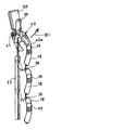
本実施例のブラインドシャッター制御装置は構造物の開口部を開閉する電動シャッター装置10に適用したものである。図1は、窓などの開口部に適用された電動シャッター装置10を室内側から見た図である。電動シャッター装置10は、図1に示すように、モータ11と、モータ11によって回転駆動する巻き取り軸12と、縦方向に延びる平行に並走された2本のガイドレール部15と、ガイドレール部15に沿って昇降され昇降に伴い開口部を開閉させるシャッターカーテン(シャッター)13と、モータ11および巻き取り軸12を格納する格納ボックス16とを備える。なお、モータ11は後述するアクチュエータ50とともにブラインド駆動部(駆動部)を構成する。そして、本実施例のブラインドシャッター制御装置は、例えば格納ボックス16内に内蔵される。
Example 1
The blind shutter control device of this embodiment is applied to an
まず、本実施例のブラインドシャッター制御装置で制御される電動シャッター装置10のシャッターカーテン13の開閉およびブラインドの開閉の仕組みについて説明する。
First, the mechanism of opening and closing the
モータ11は、シャッターカーテン13を巻き取り方向および巻き戻し方向にそれぞれ回転可能とされている。従って、モータ11により回転される巻き取り軸12は、シャッターカーテン13を巻き取り方向(矢印Y1方向)および巻き戻し方向(矢印Y2方向)に回転可能になっている。即ち、モータ11の一方向の回転により、シャッターカーテン13が巻き取り軸12に巻き取られ上昇(開放)する。モータ11の他方向への回転により、シャッターカーテン13が巻き取り軸12から巻き戻されて繰り出され下降(閉鎖)する。そして、モータ11は、後述するコントローラ(ブラインド開放信号出力手段、入力手段)300によって作動する。
The
そして、モータ11のモータ軸には、ロータリ式のエンコーダなどのモータ作動検出器111が設けられている。モータ11が駆動してシャッターカーテン13が閉鎖方向または開放方向に駆動するとき、エンコーダなどのモータ作動検出器111から出力された信号は、後述する制御部100に入力される。制御部100のメモリ104に書き込まれているシャッター位置検出手段はエンコーダなどのモータ作動検出器111の信号に基づいて、モータ11の回転量、モータ11の回転速度、ひいてはシャッターカーテン13の下端の現在位置を検出することができ、これによりシャッターカーテン13の下端が全閉位置あるいは全開位置に到達したか否かを検出することができる。検出された位置はその都度、制御部100のメモリ103に記憶させておく。
A motor operation detector 111 such as a rotary encoder is provided on the motor shaft of the
シャッターカーテン13は、下端を構成する座板17と、座板17より上側の部分を構成する多数のスラット18とによって構成されている。スラット18は横長に延設されており、上下方向に沿って複数個並設されている。スラット18は、スラット18をシャッターカーテンとして使用するシャッター使用形態と、スラット18をブラインドとして使用するブラインド使用形態とに切替可能とされている。
The
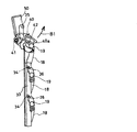
スラット18には、図2に示すように、各スラット18の横方向の外方に延出してガイドレール部15内に至る連結軸部19が一体的に連結されている。連結軸部19の先端部には、取付具としてのネジ20xによりリンク21が、スラット18を回動可能ならしめるように、固定されている。リンク21の上端部には連結ピン22が植設されている。この連結ピン22は、これの直上に位置するリンク21の下端部に形成された長孔23内に回動可能に嵌合されている。複数のスラット18のうち最も下側のスラット18のリンク21の長孔23内には、座板17に固定されたブラケット24に植設されたピン25が嵌合されている。各スラット18の端部には、連結軸部19の上側に位置して横外方向に延出する係止体としての旋回軸26が設けられている。なお、図2〜図6では、図面の複雑化を避けるため、スラット18の枚数を実際よりも少なくして図示している。
As shown in FIG. 2, a connecting
図2に示されるように、ガイドレール部15の内端面には、断面が円形のガイド部30が上下方向に沿って長く延在している。このガイド部30は、リブ31を介してガイドレール部15と一体形成されている。断面が略L型の切替部材33の基端部がガイド部30に沿って上下方向に延在しており且つガイド部30を中心として回動可能になっている。切替部材33の先端部には、複数の切り欠き部34が上下方向に間隔を隔てて均等ピッチで形成されている。切り欠き部34は、室外側を指向するとともに斜め下方向に開口するように形成されている。
As shown in FIG. 2, a
ガイドレール部15には、ピン35を介してカム体36の上端部が回動可能に枢着されている。カム体36の下端部は、切替部材33の基端部側に当接している。なお、図示しないスプリングが切替部材33を室内方向に付勢している。これにより、この当接が常時維持されるようになっている。カム体36の中央域にはピン38により捕捉部材40が回動可能に枢着されている。捕捉部材40はガイドレール部15に回動可能に枢着される。捕捉部材40は、先端開口を有する被係止部としてのスロット42が形成されている。このスロット42の開口の先端部は係り部40aとされている。また、捕捉部材40はスロット42の上方にカム溝43が刻設されている。
An upper end portion of a
捕捉部材40の近傍には、ブラインド駆動部のアクチュエータ50が配設されている。アクチュエータ50は上下動可能なプランジャ51をもつ。プランジャ51の先端部にはピン52が植設されている。ピン52の先端部は、捕捉部材40のカム溝43内に摺動可能に挿入されている。アクチュエータ50が作動していない第1位置(シャッター使用形態)に設定されているときは、プランジャ51のストロークは最大となっている。つまり、プランジャ51の本体部からの突出量は最大となっている。これに対して、アクチュエータ50が作動して第2位置(ブラインド使用形態)に切り替えられると、プランジャ51がアクチュエータ50の本体内に引き込まれる。その後、モータ11の駆動により、巻き取り軸12が巻き取り方向に回動し、シャッターカーテン13が矢印Y1方向に上昇し、開放方向に移動する。
In the vicinity of the
このとき、捕捉部材40はピン41を中心として図示反時計方向(図3の矢印B1方向、ブラインド使用方向)に所定角度(例えば約25度)回動する。このように捕捉部材40がピン41を中心として回動すると、図4に示されるように、捕捉部材40の係り部40aは、矢印B1方向(ブラインド使用方向)に変位し、スラット18の連結軸部19の昇降移動軌跡上(ブラインド使用形態)に切り替えられる。故に、巻き取り軸12の回動に伴い矢印Y1方向に上昇してくる直下のスラット18の連結軸部19が、図4に示されるように、捕捉部材40の下側から、捕捉部材40の係り部40aに当たって係合する。この結果、巻き取り軸12の回転に伴い、直下のスラット18は上昇し続けるため、図5に示されているように、そのスラット18の連結軸部19は捕捉部材40の係り部40aを押し上げる。従って、捕捉部材40は反時計方向(矢印B1方向、ブラインド使用方向)に、所定角度更に回動する。
At this time, the capturing
このように捕捉部材40がピン41を中心として矢印B1方向に回動すると、捕捉部材40のカム溝43によりカム体36は押圧され、ひいては、カム体36はピン35を中心として所定角度、反時計方向(矢印B1方向、ブラインド使用方向)に回動する。この結果、図5に示されるよう、捕捉部材40に最も近い、上昇してくる直下のスラット18の連結軸部19は捕捉部材40のスロット42に入り込む。また、後続のスラット18の係止体である旋回軸26は、切替部材33の切り欠き部34の奥方にそれぞれ入り込む。
When the
ここで、モータ11の駆動が継続して巻き取り軸12の巻き取り方向への回転が継続しているため、シャッターカーテン13が矢印Y1方向に上昇せんとする。すると、図6に示されているように、スラット18の旋回軸26が切替部材33の切り欠き部34に拘束され、それ以上上昇できない。このように旋回軸26が切り欠き部34に拘束された状態において、モータ11により巻き取り軸12が巻き取り方向に回動しているため、スラット18の連結軸部19が上昇せんとするため、スラット18が旋回軸26を回動中心として矢印M1方向(図6参照、ブラインド開方向)に回動する。この上昇量を調整することにより、スラット18のブラインド開度(回動角度)を調整することができる。
Here, since the driving of the
スラット18が閉位置からどれくらいの角度で開放されているかを示すブラインド開度は、制御部100のメモリ104に書き込まれているブラインド開度検出手段によって求められる。ブラインド開度検出手段は、モータ11のモータ軸に設けられたモータ作動検出器111が制御部100に送信した信号に基づいて、モータ11の回転量、モータ11の回転速度などから演算してスラット18の現在のブラインド開度を検出することができ、これによりスラット18の閉位置あるいは全開位置に到達したか否かを検出することができる。
The blind opening indicating how much the
シャッターカーテン13の開閉およびスラット18をブラインドとして開閉するにはブラインドシャッター制御装置のコントローラ300に操作を入力する。コントローラ300が有する操作スイッチは、図7に示すように、シャッターカーテン13を上昇させることを指示するシャッター開スイッチ301と、シャッターカーテン13を下降させることを指示するシャッター閉スイッチ302と、シャッターカーテン13の上昇または下降を停止させるシャッター停止スイッチ303と、スラット18をブラインドとして開回動させるブラインド開スイッチ304と、スラット18をブラインドとして閉回動させるブラインド閉スイッチ305がある。そして、コントローラ300は、各スイッチが操作(ON)されて、各スイッチに応じた信号を制御部100に出力する。よって、コントローラ300は、ブラインド開放信号出力手段(開放信号出力手段)として、かつ入力手段として機能する。
To open / close the
コントローラ300から出力された信号は、図8に示すように、制御部(制御手段)100に入力される。本実施例のブラインドシャッター制御装置は、図3に示すように、モータ11の駆動を制御する制御部100と、記憶手段として書き込み可能なメモリ103(EPROMなど)と、プログラムなどを格納した書き込みできないメモリ104(ROM等)とを有する。
The signal output from the
制御部100の書き込みできないメモリ104には、ブラインド開度調節手段(通常モード)と、ブラインド登録位置回動手段と、準備手段と、通電判定手段と、シャッター位置検出手段と、ブラインド開度検出手段として機能するプログラムが予め書き込まれている。 The memory 104 that cannot be written to by the control unit 100 includes a blind opening adjustment unit (normal mode), a blind registration position rotation unit, a preparation unit, an energization determination unit, a shutter position detection unit, and a blind opening detection unit. Is written in advance.
ブラインド開度調節手段は、コントローラ300から出力された信号に基づいて、モータ11とアクチュエータ50とを制御し、使用者の所望のブラインド開度になるようにスラット18を開閉回動させる。ブラインド開度調節手段では、コントローラ300のブラインド開スイッチ304またはブラインド閉スイッチ305を押し続けると、押し続けている間スラット18が開閉回動する。あるいは、スイッチを一回操作すると一定のブラインド開度ほど回動、例えば約10度、20度、30度あるいは90度、80度、70度のように約10度ずつ回動する。回動する一定のブラインド開度は10度に限らず、1度、5度、15度、20度ずつなどどのような角度でも良い。
The blind opening adjusting means controls the
ブラインド登録位置回動手段は、スラット18を閉位置から登録されたブラインド登録位置、例えばブラインド開度が約70度にスラット18を開放する手段である。スラット18が閉じているときに、コントローラ300のブラインド開スイッチ304がONされた場合に、ブラインド登録位置回動手段が作動する。ここで、ブラインド登録位置としてのブラインド開度は、スラット18を開放した際に雨が入らない90度以内で、且つ従来のブラインド開スイッチでスラット18を開放する際のブラインド開度より十分に大きい。例えば、約20度(25度、30度など)<ブラインド登録位置のブラインド開度<約90度である。ブラインド登録位置は、その他にスラット18を開放した時に、直射日光が室内に進入しない角度あるいは室外の他者に室内を容易にのぞき見ることができない角度などでもある。
The blind registration position rotating means is a means for opening the
準備手段は、コントローラ300のブラインド開スイッチ304がONされたとき、シャッターカーテン13がスラット18をブラインドとして回動することができるシャッターカーテン13の目標位置ではない場合に、目標位置までシャッターカーテン13を開放方向あるいは閉鎖方向に駆動する手段である。本実施例で使用する電動シャッター装置10の座板17の下端の位置としては、座板17の下端が着地した状態が着地位置、座板17の下端が着地し更にスラット18同士の上下方向の隙間がなくなるまでシャッターカーテン13が閉鎖方向に駆動した状態が全閉位置、座板17直上のスラット18が格納ボックス16に格納された状態が全開位置である。ここで、目標位置としては、座板17が着地位置付近から全開位置よりスラット18の上下方向1枚分ほどシャッターカーテン13が閉鎖方向(矢印Y2方向)に駆動した状態を示す。なお、全閉位置では、防犯上の理由によりスラット18をブラインドとして開放しない安全対策がなされている。
When the
そして、準備手段は、目標位置を自動的に算出し、算出した目標位置を記憶するシャッター目標位置記憶手段を有する。シャッター目標位置記憶手段は、電動シャッター装置10を設置した際にシャッターカーテン13の着地位置、全閉位置および全開位置の位置が決まったところで、それらの位置情報から自動的に目標位置を算出する。つまり、電動シャッター装置10を使用者あるいは施工業者が開口部に設置した際に設置した状態に合わせて自動的に算出され、制御部100のメモリ103に書き込まれる。よって、準備手段はこの目標位置をメモリ103から読み出し、シャッターカーテン13を目標位置まで開放または閉鎖させる。
The preparation means includes shutter target position storage means for automatically calculating the target position and storing the calculated target position. When the
通電判定手段は、スラット18の開閉の際に、アクチュエータ50に通電をするかどうか判定する手段である。スラット18の開閉は、上記したようにアクチュエータ50およびモータ11の駆動により行われ、スラット18のブラインド開度によってはアクチュエータ50を駆動させなくてもモータ11によってシャッターカーテン13が上昇または下降することでスラット18が回動できる。よって、アクチュエータ50に通電しなくてもスラット18が開閉回動できるのであれば、通電を切ることで省エネになり、またアクチュエータ50の駆動に伴う雑音も低減することができる。
The energization determining means is a means for determining whether or not the
図9は、スラット18をブラインドとして開放させるときにおいて、本実施例のブラインドシャッター制御装置の制御部100が実行するサブルーチンのフローチャートを示す。本フローチャートは、図9に示されるものに限定されるのではなく、あくまでも一例である。図9において、スラット18をブラインドとして開放するためにコントローラ300のブラインド開スイッチ304が操作(ON)されるのを待つ(ステップS401およびステップS402)。ブラインド開スイッチ304がONされると、まず、シャッターカーテン13の位置をシャッター位置検出手段から取得し(ステップS403)、スラット18がブラインドとして開放できる目標位置にシャッターカーテン13が上昇しているか否かを判定する(ステップS404)。シャッターカーテン13が目標位置でない場合は、シャッターカーテン13を目標位置まで上昇させる準備手段を実行する(ステップS405)。シャッターカーテン13が目標位置に達している場合は、スラット18のブラインド開度をブラインド開度検出手段から取得する(ステップS406)。そして、取得したブラインド開度が閉位置(ブラインド開度=約0度)であるか否かを判定する(ステップS407)。スラット18が閉位置の場合はスラット18をブラインド登録位置まで一度で開放するためのブラインド登録位置回動手段に進み(ステップS408)、スラット18が閉位置以外の場合はスラット18のブラインド開度を微調節しながら所望のブラインド開度にするブラインド開度調節手段に進む(ステップS409)。
FIG. 9 shows a flowchart of a subroutine executed by the control unit 100 of the blind shutter control device of this embodiment when the
上記したステップS408のブラインド登録位置回動手段の代表的な制御として、フローチャートを図10に示す。本フローチャートは、図10に示されるものに限定されるのではなく、あくまでも一例である。ブラインド登録位置回動手段は、まず制御部100のメモリ103からブラインド登録位置を取得する(ステップS501)。そして、スラット18を開放させるブラインド開動作を実行し(ステップS502)、ブラインド開度検出手段からスラット18の現在のブラインド開度を取得する(ステップS503)。現在のスラット18のブラインド開度がブラインド登録位置がどうか判定し(ステップS504)、ブラインド登録位置のブラインド開度でなければステップS502のブラインド開動作に戻る。スラット18の現在のブラインド開度がブラインド登録位置であれば、ブラインド登録位置回動手段を終了する。
As a representative control of the blind registration position rotating means in step S408 described above, a flowchart is shown in FIG. This flowchart is not limited to that shown in FIG. 10, but is merely an example. First, the blind registration position rotation means acquires the blind registration position from the memory 103 of the control unit 100 (step S501). Then, a blind opening operation for opening the
上記したステップS504のブラインド開動作の代表的な制御として、フローチャートを図11に示す。本フローチャートは、図11に示されるものに限定されるのではなく、あくまでも一例である。ブラインド開動作は、まずスラット18を開放回動させるのにアクチュエータ50に通電が必要かどうか判定する通電判定手段を実行する(ステップS601)。そして、モータ11を巻き取り方向に回転させるモータ開動作を実行し(S602)、シャッターカーテン13を上昇させる。
As a typical control of the blind opening operation in step S504 described above, a flowchart is shown in FIG. This flowchart is not limited to that shown in FIG. 11, but is merely an example. In the blind opening operation, first, an energization determining unit that determines whether the
上記したステップS602の通電判定手段の代表的な制御として、フローチャートを図12に示す。本フローチャートは、図12に示されるものに限定されるものではなく、あくまで一例である。通電判定手段は、ブラインド開度検出手段からスラット18の現在のブラインド開度を取得する(ステップS801)。そして、現在のブラインド開度がアクチュエータ50に通電を要するか否かを判定する(ステップS802)。アクチュエータ50に通電の必要がなければアクチュエータ50に通電せず、通電の必要があればアクチュエータ50に通電し、ブラインド開動作に戻る。
As a representative control of the energization determining means in step S602 described above, a flowchart is shown in FIG. This flowchart is not limited to that shown in FIG. 12, but is merely an example. The energization determining means acquires the current blind opening degree of the
上記したステップS409のブラインド開度調節手段の代表的な制御として、フローチャートを図13に示す。本フローチャートは、図13に示されるものに限定されるのではなく、あくまでも一例である。ブラインド開度調節手段は、スラット18をブラインドとして開放するためにコントローラ300のブラインド開スイッチ304がONされるのを待つ(ステップS701およびステップS702)。ブラインド開スイッチ304がONされると、ブラインド開度検出手段から現在のスラット18のブラインド開度を取得し(ステップS703)、スラット18が全開位置(例えば、ブラインド開度=約110度)であるかどうかを判定する(ステップS704)。ステップS704でスラット18のブラインド開度が全開であれば、ステップS701の待機に戻り、コントローラ300に次の操作が入力されるのを待つ。スラット18のブラインド開度が全開でなければ、ブラインド開動作を実行し(ステップS705)、ステップS701の待機に戻る。
As a representative control of the blind opening degree adjusting means in step S409 described above, a flowchart is shown in FIG. This flowchart is not limited to that shown in FIG. 13, but is merely an example. The blind opening adjusting means waits for the
ステップS702において、コントローラ300のブラインド開スイッチ304以外のスイッチがONされた場合は、コントローラ300のブラインド閉スイッチ305がONされたかどうか判定する(ステップS706)。ブラインド閉スイッチ305がONされた場合は、ブラインド開度検出手段から現在のスラット18のブラインド開度を取得し(ステップS707)、スラット18が閉位置(ブラインド開度=約0度)であるかどうかを判定する(ステップS708)。スラット18の状態が閉位置でなければ、スラット18を閉鎖するためにブラインド閉動作を実行し(ステップS709)、ステップS701の待機に戻る。スラット18が閉位置の場合は、ブラインド開度調節手段を終了する。ステップS706のブラインド閉スイッチ305の判定において、ブラインド閉スイッチ305がONされていないのであれば、コントローラ300に他の操作が入力されたかどうか判定する(ステップS710)。コントローラ300に他の操作が入力されていれば、ブラインド開度調節手段を終了し、そうでなければステップS701の待機に戻る。
If a switch other than the blind
上記したステップS709のブラインド閉動作の代表的な制御として、フローチャートを図14に示す。本フローチャートは、図14に示されるものに限定されるのではなく、あくまでも一例である。ブラインド閉動作は、まずスラット18を閉鎖回動させるのにアクチュエータ50に通電が必要かどうか判定する通電判定手段を実行する(ステップS603)。そして、モータ11を巻き戻し方向に駆動し(S604)、シャッターカーテン13を下降させる。
As a representative control of the blind closing operation in step S709 described above, a flowchart is shown in FIG. This flowchart is not limited to that shown in FIG. 14, but is merely an example. In the blind closing operation, first, an energization determining means for determining whether the
ここで、コントローラ300への入力操作について説明する。スラット18が閉位置でコントローラ300のブラインド開スイッチ304がONされた場合は、ブラインド登録位置(例えば70度)までスラット18が開放するが、開放途中で使用者がコントローラ300の各スイッチをONすることが考えられる。本実施例のフローチャートでは、スラット18がブラインド登録位置に到達するまで一切の割り込みを受け付けない。しかし、割り込みを受け付けスラット18の開放を停止する制御も考えられる。あるいは、ブラインド登録位置開放中にブラインド開スイッチ304がONされた場合は、ブラインド登録位置以外の別の特定のブラインド開度で停止させる制御とすることもできる。
Here, an input operation to the
本実施例のブラインドシャッター制御装置によれば、スラット18が閉位置のときにコントローラ300のブラインド開スイッチ304がONされた場合に、ブラインド登録位置回動手段がスラットをブラインド登録位置(約70度)まで一度で回動させることができる。つまり、ブラインド開度調節手段でスラット18を開放されるより使用者の操作量が減る。また、使用者がブラインド開スイッチ304を押し続けたとしてもコントローラ300から制御部100に送られる出力信号はスラット18を70度に開放するという信号だけであり、信号量を少なくすることができるので、消費電力の低減も可能である。
According to the blind shutter control device of the present embodiment, when the
また、準備手段によれば、シャッター位置検出手段で取得したシャッターカーテン13の位置がスラット18をブラインドとして開閉回動させることができる位置である目標位置でない場合に、シャッターカーテン13を目標位置まで開閉可動させることができる。そして、シャッターカーテン13が目標位置まで開放された後は、スラット18を開放回動させるので、一度の入力操作でスラット18が開放し、使用者の入力操作が軽減されるので、使い勝手が良い。
Further, according to the preparation means, when the position of the
そして、目標位置はシャッター目標位置記憶手段が、電動シャッター装置10を設置した際の設置された場所などの状況により自動的に算出され、算出された位置を目標位置として記憶することができる。つまり、使用者あるいは施工業者が電動シャッター装置10を設置を設置した際に目標位置を設定する必要がなく且つ適切な目標位置が自動算出されるので、設定の手間を低減できる。なお、目標位置は所定の範囲を含み、一点に限られない。
The target position is automatically calculated by the shutter target position storage unit according to the situation such as the place where the
そして、スラット18のブラインド登録位置のブラインド開度が直角以下とすることで、雨天時にスラット18をブラインドとして開放した際に、スラット18の隙間から雨が入り込むのとスラット18に付着した水滴が室内側に流れ込むのとを防止でき、雨垂れ防止などの部材を省略することができ、それに伴うコストも抑えられる。また、直射日光の進入や室外の他者に室内を容易にのぞき見られたりするのを防ぐことができる。
By setting the blind opening of the blind registration position of the
(実施例2)
本発明の実施例2について具体的に説明する。本実施例は実施例1と基本的には同様の構成および同様の作用効果を有する。以下、異なる部分を中心に説明する。
(Example 2)
Example 2 of the present invention will be specifically described. The present embodiment basically has the same configuration and the same function and effect as the first embodiment. The following description will focus on the different parts.
本実施例のブラインドシャッター制御装置は、図15に示すように、コントローラ300にユーザ登録スイッチ306が追加される。このユーザ登録スイッチ306は、スラット18のブラインド登録位置を70度とは別にユーザの好みのブラインド開度で登録することができ且つそのブラインド開度にスラット18を回動するスイッチであるので、設定登録手段および登録位置回動信号出力手段として機能する。便宜上、ユーザの好みのブラインド開度であるブラインド登録位置は、ユーザ登録位置(ブラインド登録位置)とする。
In the blind shutter control device of the present embodiment, a
コントローラ300は、ユーザ登録スイッチ306が操作(ON)された場合にユーザ登録位置、例えば45度にスラット18を回動させるための信号を制御部100に出力する。そして、ユーザ登録位置にユーザの好みのブラインド開度を登録するには、ユーザ登録スイッチ306を長押しする。コントローラ300は、ユーザ登録スイッチ306を長押しされた際のブラインド開度をユーザ登録位置として設定登録するための信号を制御部100に出力する。制御部100では、メモリ103のユーザ登録位置を現在のブラインド開度に更新する。登録するブラインド開度を検出するタイミングとしては、スラット18が停止している際はその停止している開度であり、スラット18が回動途中の場合は押された瞬間にスラット18の回動を停止し、その停止した開度である。
When the
図16は、実施例1の図9に示されるスラット18をブラインドとして開放させるために制御部100が実行するサブルーチンのフローチャートに、ユーザ登録スイッチ306がONされた場合を追加したフローチャートである。本フローチャートは、図16に示されるものに限定されるのではなく、あくまでも一例である。図16において、ステップS402のブラインド開スイッチ304がONされたと判定された場合の流れは実施例1と同様であるため説明を省略する。ステップS402でブラインド開スイッチ304がONされたのではないと判定された場合は、ユーザ登録スイッチ306がONされたかどうかを判定する(ステップS410)。ユーザ登録スイッチ306をONされたのではない場合は、ステップS401に戻りブラインド開スイッチ304、ユーザ登録スイッチ306がONされるか別のスイッチがONされるのを待つ。そして、ユーザ登録スイッチ306がONされた場合は、スイッチ306が長押しされたかどうかを判定する(ステップS411)。ユーザ登録スイッチ306が長押しされた場合は、その際のブラインド開度をブラインド開度検出手段を実行して取得し(ステップS412)、そのブラインド開度にユーザ登録位置を更新する(ステップS413)。ユーザ登録スイッチ306が長押しではなくONされた場合は、シャッターカーテン13の位置を取得し(ステップS414)、その位置がスラット18をブラインドとして開放できる目標位置がどうか判定する(ステップS415)。シャッターカーテン13が目標位置でない場合は目標位置に駆動する準備手段を実行し(ステップS416)、目標位置であればステップS408のブラインド登録回動手段を実行する。
FIG. 16 is a flowchart in which the case where the
上記のステップS408のブラインド登録位置回動手段の代表的な制御として、フローチャートを図17に示す。本フローチャートは、図17に示されるものに限定されるものではなく、あくまで一例である。ブラインド登録位置回動手段は、まず制御部100のメモリ103からブラインド登録位置(ユーザ登録位置)を取得する(ステップS505)。ブラインド登録位置は、70度かユーザの好みの45度かは上記フローチャートでブラインド登録位置回動手段が実行された時点で区別される。次に、現在のスラット18のブラインド開度をブラインド開度検出手段によって取得する(ステップS506)。そして、現在のブラインド開度がブラインド登録位置であるかどうか判定し(ステップS507)、ブラインド登録位置であればブラインド登録位置回動手段を終了し、そうでなければブラインド登録位置と現在のブラインド開度とを比べる(ステップS508)。現在のブラインド開度がブラインド登録位置より狭い場合はブラインド開動作を実行し(ステップS509)、広い場合はブラインド閉動作を実行する(ステップS510)。
As a representative control of the blind registration position rotating means in step S408, a flowchart is shown in FIG. This flowchart is not limited to that shown in FIG. 17, but is merely an example. The blind registration position rotating means first acquires the blind registration position (user registration position) from the memory 103 of the control unit 100 (step S505). Whether the blind registration position is 70 degrees or the user's favorite 45 degrees is distinguished when the blind registration position rotating means is executed in the flowchart. Next, the current blind opening degree of the
本実施例2のブラインドシャッター制御装置によれば、ブラインド登録位置が70度のように初期設定されている以外にユーザの好みのブラインド開度を登録し、そのブラインド開度にスラット18を回動することができる。
According to the blind shutter control device of the second embodiment, the blind opening position of the user is registered in addition to the blind registration position being initially set to 70 degrees, and the
コントローラ300は、図15に示すように、ユーザ登録位置にスラット18を回動させるのも登録するのもスイッチ1つで行ったが、設定登録用に別に設定登録手段としてのスイッチを設けることもできる。また、ユーザ登録位置は1つとは限らず複数、つまり初期設定されている70度以外にも多数のブラインド開度をブラインド登録位置として設定登録し、その開度にスラット18を回動させることができるように必要な数のスイッチを追加することができる。そして、ブラインド登録位置の設定登録はスラット18が停止している状態でも回動途中でもユーザ登録信号出力手段が操作され制御部100に信号が出力される。回動途中に押された場合は、スラット18の回動を停止しても停止しなくても良い。押された時点でのブラインド開度がブラインド開度検出手段によって取得される。
As shown in FIG. 15, the
(実施例3)
本発明の実施例3について具体的に説明する。本実施例は実施例1または実施例2と基本的には同様の構成および同様の作用効果を有する。以下、異なる部分を中心に説明する。
(Example 3)
Example 3 of the present invention will be specifically described. The present embodiment basically has the same configuration and the same function and effect as the first or second embodiment. The following description will focus on the different parts.
本実施例のブラインドシャッター制御装置は、コントローラ300と入室検知センサー(図示略)とを有する。入室検知センサーは、電動シャッター装置10が設置されている室内に人が入室したのを検知できる箇所に設置され、人が入室したのを検知し、制御部100に信号を出力するので、ブラインド開放信号出力手段として機能する。ブラインドシャッター制御装置は、入室検知センサーから制御部100に信号が出力された場合に、スラット18が閉位置であればブラインド開スイッチ304をONした場合と同様にブラインド登録位置(例えば70度)にスラット18を開回動させる。入室検知センサーにより人の入室を検知してスラット18を開放させることで、コントローラ300を操作する手間を低減することができる。
The blind shutter control device of this embodiment includes a
(実施例4)
本発明の実施例4について説明する。本実施例は実施例1、実施例2または実施例3と基本的には同様の構成および同様の作用効果を有する。以下、異なる部分を中心に説明する。
Example 4
Embodiment 4 of the present invention will be described. This embodiment basically has the same configuration and the same function and effect as those of the first, second, or third embodiment. The following description will focus on the different parts.
本実施例のブラインドシャッター制御装置は、ブラインド登録位置にスラット18を回動させるようにモータ11の駆動量としてモータ11を駆動する時間が制御部100のメモリ103に設定されている。
In the blind shutter control device of this embodiment, a time for driving the
コントローラ300は、ブラインド開スイッチ304またはユーザ登録スイッチ306が操作(ON)あるいは入室検知センサーは入室が検知されると、制御部100に信号を出力し、メモリ103から出力信号に対応したモータ11の駆動量を取得し、モータ11およびアクチュエータ50を駆動し、スラット18を回動させる。
When the
10:電動シャッター装置、11:モータ、12:巻き取り軸、13:シャッターカーテン(シャッター)、15:ガイドレール部、16:格納ボックス、17:座板、18:スラット、19:連結軸部、20x:ネジ、21:リンク、22:連結ピン、23:長孔、24:ブラケット、25,35,38,41,52:ピン、26:旋回軸、30:ガイド部、31:リブ、33:切替部材、34:切り欠き部、36:カム体、40:捕捉部材、40a:係り部、42:スロット、43:カム溝、50:アクチュエータ、51:プランジャ、100:制御部、103,104:メモリ、111:モータ作動検出器、300:コントローラ(ブラインド開放信号出力手段、入力手段)、301:シャッター開スイッチ、302:シャッター閉スイッチ、303:シャッター停止スイッチ、304:ブラインド開スイッチ、305:ブラインド閉スイッチ、306:ユーザ登録スイッチ。 10: Electric shutter device, 11: Motor, 12: Winding shaft, 13: Shutter curtain (shutter), 15: Guide rail section, 16: Storage box, 17: Seat plate, 18: Slat, 19: Connecting shaft section, 20x: Screw, 21: Link, 22: Connection pin, 23: Long hole, 24: Bracket, 25, 35, 38, 41, 52: Pin, 26: Rotating shaft, 30: Guide part, 31: Rib, 33: Switching member, 34: Notch part, 36: Cam body, 40: Capture member, 40a: Engagement part, 42: Slot, 43: Cam groove, 50: Actuator, 51: Plunger, 100: Control part, 103, 104: Memory: 111: Motor operation detector, 300: Controller (blind open signal output means, input means), 301: Shutter open switch, 302: Shutter close switch Pitch, 303: shutter stop switch, 304: blind opening switch, 305: blind closed switch, 306: user registration switch.
Claims (9)
前記スラットのブラインド開度を変更するための信号が出力されるブラインド開放信号出力手段と、
前記ブラインド駆動部を駆動させる制御手段と、を有するブラインドシャッター制御装置において、
前記スラットの前記ブラインド開度を検出するブラインド開度検出手段を有し、
前記制御手段は、登録された前記ブラインド開度である1または複数のブラインド登録位置に前記ブラインド開放信号出力手段の出力信号に基づいて前記スラットを回動させるブラインド登録位置回動手段と、
前記ブラインド開放信号出力手段の出力信号に基づいた前記ブラインド開度に前記スラットを開閉回動する通常モードと、を有し、
前記ブラインド登録位置回動手段は、前記ブラインド登録位置に前記スラットを回動させるために前記ブラインド開放信号出力手段が出力する信号量が、前記通常モードで前記ブラインド登録位置に前記スラットを回動させるために前記ブラインド開放信号出力手段が出力する信号量より少なく、
前記制御手段は、
前記ブラインド開度検出手段で取得した前記スラットの前記ブラインド開度が閉位置の場合に前記ブラインド登録位置回動手段を実行し、
前記ブラインド開度検出手段で取得した前記スラットの前記ブラインド開度が前記閉位置以外の場合に前記通常モードを実行することを特徴とするブラインドシャッター制御装置。 A blind drive unit that rotates the slats constituting the shutter as a blind, and
Blind opening signal output means for outputting a signal for changing the blind opening of the slat;
In the blind shutter control device having a control means for driving the blind drive unit,
Comprising blind opening detection means for detecting the blind opening of the slat;
The control means is a blind registration position rotating means for rotating the slat to one or a plurality of blind registration positions which are the registered blind opening based on an output signal of the blind opening signal output means,
Has a normal mode for opening and closing rotating the slats to the blind opening degree based on the output signal of the blind opening signal output means,
The blind registration position rotation means rotates the slat to the blind registration position in the normal mode based on the signal amount output by the blind opening signal output means for rotating the slat to the blind registration position. the blind opening signal output means rather less than the signal amount to be output to,
The control means includes
When the blind opening of the slat acquired by the blind opening detection means is a closed position, the blind registration position rotation means is executed,
The blind shutter control device , wherein the normal mode is executed when the blind opening degree of the slat acquired by the blind opening degree detection means is other than the closed position .
前記ブラインド登録位置回動手段は、前記ブラインド登録位置に前記スラットを回動させるために前記入力手段に入力する操作量が、前記通常モードで前記ブラインド登録位置に前記スラットを回動させるために前記入力手段に入力する操作量より少ないことを特徴とするブラインドシャッター制御装置。 According to claim 1, wherein, prior Symbol blind opening signal output means includes input means for operation is input to change the blind opening of the slats,
The blind registration position rotation means is configured such that an operation amount input to the input means for rotating the slat to the blind registration position is set to rotate the slat to the blind registration position in the normal mode. A blind shutter control device characterized in that the amount of operation is less than the amount of operation input to the input means.
前記ブラインド開放信号出力手段から信号が出力されたときに前記シャッター位置検出手段で取得した前記シャッターの位置が目標位置でない場合に、前記シャッターを前記目標位置まで開閉させる準備手段と、を更に有することを特徴とするブラインドシャッター制御装置。 In any one of Claims 1-3 , The shutter position detection means which detects the position of the shutter in the opening-and-closing direction of the shutter,
And a preparation means for opening and closing the shutter to the target position when the position of the shutter acquired by the shutter position detection means when the signal is output from the blind opening signal output means is not the target position. A blind shutter control device.
前記制御手段は、前記スラットの前記ブラインド開度に応じて、前記アクチュエータに通電の要否を判断する通電判定手段を更に有することを特徴とするブラインドシャッター制御装置。 In any one of Claims 1-6 , the blind drive part has an actuator which rotates the slat as a blind,
The blind shutter control device according to claim 1, wherein the control means further includes energization determining means for determining whether the actuator needs to be energized according to the blind opening of the slat.
Priority Applications (1)
| Application Number | Priority Date | Filing Date | Title |
|---|---|---|---|
| JP2008043807A JP5217492B2 (en) | 2008-02-26 | 2008-02-26 | Blind shutter control device |
Applications Claiming Priority (1)
| Application Number | Priority Date | Filing Date | Title |
|---|---|---|---|
| JP2008043807A JP5217492B2 (en) | 2008-02-26 | 2008-02-26 | Blind shutter control device |
Publications (2)
| Publication Number | Publication Date |
|---|---|
| JP2009203605A JP2009203605A (en) | 2009-09-10 |
| JP5217492B2 true JP5217492B2 (en) | 2013-06-19 |
Family
ID=41146148
Family Applications (1)
| Application Number | Title | Priority Date | Filing Date |
|---|---|---|---|
| JP2008043807A Active JP5217492B2 (en) | 2008-02-26 | 2008-02-26 | Blind shutter control device |
Country Status (1)
| Country | Link |
|---|---|
| JP (1) | JP5217492B2 (en) |
Families Citing this family (3)
| Publication number | Priority date | Publication date | Assignee | Title |
|---|---|---|---|---|
| JP6119205B2 (en) * | 2012-11-21 | 2017-04-26 | アイシン精機株式会社 | Blind shutter device |
| JP6070219B2 (en) * | 2013-01-29 | 2017-02-01 | アイシン精機株式会社 | Blind shutter device |
| JP6122081B1 (en) * | 2015-10-20 | 2017-04-26 | 積水ハウス株式会社 | Blind shutter |
Family Cites Families (1)
| Publication number | Priority date | Publication date | Assignee | Title |
|---|---|---|---|---|
| JP4494623B2 (en) * | 2000-12-18 | 2010-06-30 | 文化シヤッター株式会社 | Switchgear |
-
2008
- 2008-02-26 JP JP2008043807A patent/JP5217492B2/en active Active
Also Published As
| Publication number | Publication date |
|---|---|
| JP2009203605A (en) | 2009-09-10 |
Similar Documents
| Publication | Publication Date | Title |
|---|---|---|
| US11834903B2 (en) | Motor assemblies for architectural coverings | |
| US20230349227A1 (en) | Motorized sheer shading system | |
| AU2007200200B2 (en) | Push button control for motorized coverings with light control | |
| US11486198B2 (en) | Motor assemblies for architectural coverings | |
| JP5217492B2 (en) | Blind shutter control device | |
| JP6200513B2 (en) | Shutter device and control method of shutter device | |
| US9328556B2 (en) | Motorized transitional shade system | |
| JP3912135B2 (en) | Alarm control device for switching body | |
| KR200403058Y1 (en) | Automatic and manual selection window curtain unit | |
| JP5135053B2 (en) | Control device for electric horizontal blind and method for rotating slats of electric horizontal blind | |
| KR200410638Y1 (en) | Built-in gear blind device | |
| JP4770056B2 (en) | Shutter device | |
| KR20170068905A (en) | Blind with sound effect function | |
| JP7474127B2 (en) | Shielding material control device and shielding material control method | |
| KR20170112162A (en) | Automatic shading device in the room | |
| JP2584203B2 (en) | Electric blind device | |
| JP2002168073A (en) | Control device for daylighting for shutter | |
| KR200373379Y1 (en) | Blind | |
| KR980008122A (en) | Slit type blind direction switching apparatus and method according to the amount of sunshine | |
| JP2008274572A (en) | Ventilation and daylighting type electric shutter apparatus |
Legal Events
| Date | Code | Title | Description |
|---|---|---|---|
| A621 | Written request for application examination |
Free format text: JAPANESE INTERMEDIATE CODE: A621 Effective date: 20110125 |
|
| A977 | Report on retrieval |
Free format text: JAPANESE INTERMEDIATE CODE: A971007 Effective date: 20120629 |
|
| A131 | Notification of reasons for refusal |
Free format text: JAPANESE INTERMEDIATE CODE: A131 Effective date: 20120830 |
|
| A521 | Request for written amendment filed |
Free format text: JAPANESE INTERMEDIATE CODE: A523 Effective date: 20121023 |
|
| TRDD | Decision of grant or rejection written | ||
| A01 | Written decision to grant a patent or to grant a registration (utility model) |
Free format text: JAPANESE INTERMEDIATE CODE: A01 Effective date: 20130205 |
|
| A61 | First payment of annual fees (during grant procedure) |
Free format text: JAPANESE INTERMEDIATE CODE: A61 Effective date: 20130218 |
|
| FPAY | Renewal fee payment (event date is renewal date of database) |
Free format text: PAYMENT UNTIL: 20160315 Year of fee payment: 3 |
|
| R151 | Written notification of patent or utility model registration |
Ref document number: 5217492 Country of ref document: JP Free format text: JAPANESE INTERMEDIATE CODE: R151 |
|
| FPAY | Renewal fee payment (event date is renewal date of database) |
Free format text: PAYMENT UNTIL: 20160315 Year of fee payment: 3 |
|
| S111 | Request for change of ownership or part of ownership |
Free format text: JAPANESE INTERMEDIATE CODE: R313113 |
|
| R350 | Written notification of registration of transfer |
Free format text: JAPANESE INTERMEDIATE CODE: R350 |
|
| RD02 | Notification of acceptance of power of attorney |
Free format text: JAPANESE INTERMEDIATE CODE: R3D02 |
|
| R250 | Receipt of annual fees |
Free format text: JAPANESE INTERMEDIATE CODE: R250 |
|
| R250 | Receipt of annual fees |
Free format text: JAPANESE INTERMEDIATE CODE: R250 |