JP5215733B2 - Display control apparatus and overdrive drive parameter determination method - Google Patents
Display control apparatus and overdrive drive parameter determination method Download PDFInfo
- Publication number
- JP5215733B2 JP5215733B2 JP2008140035A JP2008140035A JP5215733B2 JP 5215733 B2 JP5215733 B2 JP 5215733B2 JP 2008140035 A JP2008140035 A JP 2008140035A JP 2008140035 A JP2008140035 A JP 2008140035A JP 5215733 B2 JP5215733 B2 JP 5215733B2
- Authority
- JP
- Japan
- Prior art keywords
- region
- liquid crystal
- display control
- image
- scroll
- Prior art date
- Legal status (The legal status is an assumption and is not a legal conclusion. Google has not performed a legal analysis and makes no representation as to the accuracy of the status listed.)
- Expired - Fee Related
Links
- 238000000034 method Methods 0.000 title claims description 24
- 239000004973 liquid crystal related substance Substances 0.000 claims description 58
- 206010047571 Visual impairment Diseases 0.000 claims description 22
- 239000003086 colorant Substances 0.000 claims description 2
- 230000008859 change Effects 0.000 description 14
- 230000008569 process Effects 0.000 description 13
- 230000004044 response Effects 0.000 description 11
- 230000006870 function Effects 0.000 description 10
- 238000010586 diagram Methods 0.000 description 9
- 230000004048 modification Effects 0.000 description 8
- 238000012986 modification Methods 0.000 description 8
- 238000004040 coloring Methods 0.000 description 7
- 230000008901 benefit Effects 0.000 description 1
- 238000006243 chemical reaction Methods 0.000 description 1
- 230000000694 effects Effects 0.000 description 1
- 230000003287 optical effect Effects 0.000 description 1
- 230000003068 static effect Effects 0.000 description 1
Images


Classifications
-
- G—PHYSICS
- G09—EDUCATION; CRYPTOGRAPHY; DISPLAY; ADVERTISING; SEALS
- G09G—ARRANGEMENTS OR CIRCUITS FOR CONTROL OF INDICATING DEVICES USING STATIC MEANS TO PRESENT VARIABLE INFORMATION
- G09G3/00—Control arrangements or circuits, of interest only in connection with visual indicators other than cathode-ray tubes
- G09G3/20—Control arrangements or circuits, of interest only in connection with visual indicators other than cathode-ray tubes for presentation of an assembly of a number of characters, e.g. a page, by composing the assembly by combination of individual elements arranged in a matrix no fixed position being assigned to or needed to be assigned to the individual characters or partial characters
- G09G3/34—Control arrangements or circuits, of interest only in connection with visual indicators other than cathode-ray tubes for presentation of an assembly of a number of characters, e.g. a page, by composing the assembly by combination of individual elements arranged in a matrix no fixed position being assigned to or needed to be assigned to the individual characters or partial characters by control of light from an independent source
- G09G3/36—Control arrangements or circuits, of interest only in connection with visual indicators other than cathode-ray tubes for presentation of an assembly of a number of characters, e.g. a page, by composing the assembly by combination of individual elements arranged in a matrix no fixed position being assigned to or needed to be assigned to the individual characters or partial characters by control of light from an independent source using liquid crystals
- G09G3/3611—Control of matrices with row and column drivers
-
- G—PHYSICS
- G09—EDUCATION; CRYPTOGRAPHY; DISPLAY; ADVERTISING; SEALS
- G09G—ARRANGEMENTS OR CIRCUITS FOR CONTROL OF INDICATING DEVICES USING STATIC MEANS TO PRESENT VARIABLE INFORMATION
- G09G2320/00—Control of display operating conditions
- G09G2320/02—Improving the quality of display appearance
- G09G2320/0252—Improving the response speed
-
- G—PHYSICS
- G09—EDUCATION; CRYPTOGRAPHY; DISPLAY; ADVERTISING; SEALS
- G09G—ARRANGEMENTS OR CIRCUITS FOR CONTROL OF INDICATING DEVICES USING STATIC MEANS TO PRESENT VARIABLE INFORMATION
- G09G2320/00—Control of display operating conditions
- G09G2320/06—Adjustment of display parameters
- G09G2320/0693—Calibration of display systems
-
- G—PHYSICS
- G09—EDUCATION; CRYPTOGRAPHY; DISPLAY; ADVERTISING; SEALS
- G09G—ARRANGEMENTS OR CIRCUITS FOR CONTROL OF INDICATING DEVICES USING STATIC MEANS TO PRESENT VARIABLE INFORMATION
- G09G2340/00—Aspects of display data processing
- G09G2340/16—Determination of a pixel data signal depending on the signal applied in the previous frame
-
- G—PHYSICS
- G09—EDUCATION; CRYPTOGRAPHY; DISPLAY; ADVERTISING; SEALS
- G09G—ARRANGEMENTS OR CIRCUITS FOR CONTROL OF INDICATING DEVICES USING STATIC MEANS TO PRESENT VARIABLE INFORMATION
- G09G5/00—Control arrangements or circuits for visual indicators common to cathode-ray tube indicators and other visual indicators
- G09G5/34—Control arrangements or circuits for visual indicators common to cathode-ray tube indicators and other visual indicators for rolling or scrolling
- G09G5/346—Control arrangements or circuits for visual indicators common to cathode-ray tube indicators and other visual indicators for rolling or scrolling for systems having a bit-mapped display memory
Landscapes
- Engineering & Computer Science (AREA)
- Chemical & Material Sciences (AREA)
- Crystallography & Structural Chemistry (AREA)
- Physics & Mathematics (AREA)
- Computer Hardware Design (AREA)
- General Physics & Mathematics (AREA)
- Theoretical Computer Science (AREA)
- Control Of Indicators Other Than Cathode Ray Tubes (AREA)
- Liquid Crystal (AREA)
- Liquid Crystal Display Device Control (AREA)
- Transforming Electric Information Into Light Information (AREA)
Description
本発明は、液晶表示装置のオーバードライブ駆動用のパラメータを決定する技術に関するものである。 The present invention relates to a technique for determining parameters for overdrive driving of a liquid crystal display device.
近年、TVの受像機やPCの表示装置として液晶表示装置が使用されている。しかしながら、液晶表示装置は、入力される映像信号の変化速度(例えばフレームレート)に対して実際の表示までの液晶応答速度が比較的遅いため、例えば動画を表示した場合に残像が発生し得る。液晶表示装置の応答速度を改善するための駆動方法として、現在表示対象となる表示フレーム(現表示フレーム)の映像信号と1フレーム前の表示フレームの映像信号との組み合わせに応じて、現表示フレームの映像信号を補正して出力する、所謂オーバードライブ駆動方法が提案されている。(例えば、特許文献1)
また、特許文献2には、1フレームを複数のフィールドに分割して駆動し、最初のフィールドに対してオーバードライブ駆動を行うことにより液晶応答速度の改善効果をより大きく得る方法が開示されている。
In recent years, liquid crystal display devices have been used as TV receivers and PC display devices. However, since the liquid crystal display device has a relatively slow liquid crystal response speed until actual display with respect to the change speed (for example, frame rate) of the input video signal, an afterimage can be generated when a moving image is displayed, for example. As a driving method for improving the response speed of the liquid crystal display device, a current display frame is selected according to a combination of a video signal of a display frame (current display frame) to be displayed at present and a video signal of a display frame one frame before. A so-called overdrive driving method for correcting and outputting the video signal is proposed. (For example, Patent Document 1)
Further, Patent Document 2 discloses a method in which one frame is divided into a plurality of fields and driven, and overdrive driving is performed on the first field to obtain a greater effect of improving the liquid crystal response speed. .
図10は、オーバードライブ駆動回路を説明するための図である。図10において、1000はオーバードライブ補正処理部、120はフレームメモリ、110は表示部である。そして、オーバードライブ補正処理部1000は、補正量決定部1001、補正テーブル1002、および、補正量付加部1003を備える。
FIG. 10 is a diagram for explaining the overdrive drive circuit. In FIG. 10, 1000 is an overdrive correction processing unit, 120 is a frame memory, and 110 is a display unit. The overdrive
オーバードライブ補正処理部1000には、現フレームの映像信号とフレームメモリ120に記憶された1フレーム前の映像信号とが入力される。そして両者の信号レベルの組み合わせに応じて、補正量決定部1001は補正量を算出する。例えば、現フレームの映像信号レベルが1フレーム前の映像信号レベルよりも高い場合は、通常の駆動電圧よりも高い液晶駆動電圧で液晶パネルを駆動できるように補正量を算出する。逆に、現フレームの映像信号レベルが1フレーム前の映像信号レベルよりも低い場合は、通常よりも低い液晶駆動電圧で液晶パネルを駆動するよう算出する。
The overdrive
補正量決定部1001は、補正テーブル1002を参照し、映像信号レベルの組み合わせに対応する補正量を読み出す。なお、代表的な組み合わせのみを補正テーブル1002に格納し、他の組み合わせについては補間関数を用いて算出しても良い。補正テーブル1002に格納するデータは、信号レベルの組み合わせ毎に液晶応答速度の測定を行い、その結果に基づいて決定する。
The correction
補正量付加部1003は、補正量決定部1001により決定された補正量を現フレームの映像信号に対し加減算する。そして、表示出力部110は、入力された補正後の映像信号を液晶パネル駆動信号へ変換する。
The correction
ところで、液晶応答速度は、温度などの使用環境によって変化することが知られている。つまり使用環境によっては、補正テーブル1002のデータを決定した時の液晶応答速度と、実際に使用している表示装置の液晶応答速度が異なる場合が生じる。その場合には、算出したオーバードライブ駆動の補正量が適切な値とならず、十分な液晶応答速度の改善を行なうことができない。また、動画像のエッジ部分に不自然な色付きが生じる。 By the way, it is known that the liquid crystal response speed changes depending on the use environment such as temperature. That is, depending on the use environment, the liquid crystal response speed when the data of the correction table 1002 is determined may be different from the liquid crystal response speed of the display device actually used. In this case, the calculated overdrive drive correction amount is not an appropriate value, and the liquid crystal response speed cannot be sufficiently improved. Further, unnatural coloring occurs at the edge portion of the moving image.
そこで、特許文献3には、ユーザの指示に基づいてオーバードライブ駆動を停止させたり、強調変換度合いを変更する液晶表示装置が開示されている。また、特許文献4には、液晶表示装置の温度やユーザの指示、画像の特徴などに応じて補正量を変更する場合に、使用する補正テーブルを少なくするよう演算回路を設けた液晶表示装置が開示されている。
しかしながら、ユーザ操作によりオーバードライブ駆動の補正量調整を行なう場合、ユーザは目的とする画像がどのようなものであるかが明確に分からないまま補正量の調整を行なってしまう可能性があった。また、ユーザは本来のオーバードライブ駆動の目的とは異なる目的で補正量を設定してしまう可能性があった。このようにして不適切な補正量が設定された場合、動画像のエッジ部分の色付きやノイズが増長されるといった問題が生じることになる。 However, when adjusting the correction amount for overdrive driving by a user operation, the user may adjust the correction amount without clearly knowing what the target image is. Further, there is a possibility that the user sets the correction amount for a purpose different from the original purpose of overdrive driving. When an inappropriate correction amount is set in this way, there arises a problem that the edge portion of the moving image is colored or noise is increased.
本発明は上述の問題点に鑑みなされたものであり、ユーザが液晶表示装置のオーバードライブ駆動における補正量設定をより簡易に行なえるようにする技術を提供することを目的とする。 The present invention has been made in view of the above-described problems, and an object of the present invention is to provide a technique that allows a user to more easily set a correction amount in overdrive driving of a liquid crystal display device.
上述の問題点を解決するため、本発明の表示制御装置は以下の構成を備える。すなわち、液晶表示装置のオーバードライブ駆動用のパラメータを決定する表示制御装置において、予め設定された基準パターン画像を、前記液晶表示装置の第1の領域内で一方向に繰り返しスクロール表示させる第1の表示制御手段と、前記基準パターン画像と同一形状の複数のサンプル画像であって、各サンプル画像における前記スクロールの方向の端部が互いに異なる擬似残像領域を有する前記複数のサンプル画像を、前記液晶表示装置の第2の領域内に固定表示させる第2の表示制御手段と、前記第2の領域内に固定表示された前記複数のサンプル画像から1つのサンプル画像をユーザから選択受付する選択受付手段と、前記選択受付されたサンプル画像の前記擬似残像領域の画素値と前記基準パターン画像の前記擬似残像領域に対応する領域の画素値との差分に基づいて、前記オーバードライブ駆動用のパラメータを決定する決定手段と、を備える。
または、液晶表示装置のオーバードライブ駆動用のパラメータを決定する表示制御装置において、予め設定された基準パターン画像を、前記液晶表示装置の第1の領域内で一方向に繰り返しスクロール表示させる第1の表示制御手段と、前記基準パターン画像と同一形状のサンプル画像であって、該サンプル画像における前記スクロールの方向の端部が擬似残像領域を有する前記サンプル画像を、前記液晶表示装置の第2の領域内に固定表示させる第2の表示制御手段と、前記擬似残像領域の画素値の調整を、操作部を介してユーザから受け付ける調整受付手段と、前記調整された前記擬似残像領域の画素値と前記基準パターン画像の前記擬似残像領域に対応する領域の画素値との差分に基づいて、前記オーバードライブ駆動用のパラメータを決定する決定手段と、を備える。
In order to solve the above-described problems, the display control apparatus of the present invention has the following configuration. That is, in the display control device for determining parameters for overdrive driving of the liquid crystal display device, a first reference pattern image is repeatedly scrolled and displayed in one direction within the first region of the liquid crystal display device. A plurality of sample images having the same shape as the reference pattern image and the plurality of sample images having pseudo afterimage areas whose end portions in the scroll direction of each sample image are different from each other; Second display control means for fixedly displaying in the second area of the apparatus; and selection receiving means for selecting and receiving one sample image from the plurality of sample images fixedly displayed in the second area; A pixel value of the pseudo afterimage area of the selected sample image and the pseudo afterimage area of the reference pattern image. Based on a difference between the pixel value of the region, and a determining means for determining a parameter for the overdrive driving.
Alternatively, in the display control device that determines the parameters for overdrive driving of the liquid crystal display device, the first reference pattern image is scroll-displayed repeatedly in one direction in the first region of the liquid crystal display device. A display control means, and a sample image having the same shape as the reference pattern image, the sample image having a pseudo afterimage region at an end in the scroll direction of the sample image, the second region of the liquid crystal display device Second display control means for fixed display in the display, adjustment accepting means for accepting adjustment of the pixel value of the pseudo afterimage area from the user via an operation unit, the adjusted pixel value of the pseudo afterimage area, and the Based on the difference between the pixel value of the region corresponding to the pseudo afterimage region of the reference pattern image, the overdrive driving parameter Comprising a determining means for determining, a.
本発明によれば、ユーザが液晶表示装置のオーバードライブ(OD)駆動における補正量設定をより簡易に行なえるようにする技術を提供することができる。 ADVANTAGE OF THE INVENTION According to this invention, the technique which enables a user to perform the correction amount setting in the overdrive (OD) drive of a liquid crystal display device more easily can be provided.
以下に、図面を参照して、この発明の好適な実施の形態を詳しく説明する。なお、以下の実施の形態はあくまで例示であり、本発明の範囲を限定する趣旨のものではない。 Hereinafter, preferred embodiments of the present invention will be described in detail with reference to the drawings. The following embodiments are merely examples, and are not intended to limit the scope of the present invention.
(第1実施形態)
本発明に係る表示制御装置の第1実施形態として、液晶表示装置を例に挙げて以下に説明する。
(First embodiment)
As a first embodiment of a display control device according to the present invention, a liquid crystal display device will be described below as an example.
<装置構成>
図1は、第1実施形態に係る液晶表示装置の内部構成図である。
<Device configuration>
FIG. 1 is an internal configuration diagram of the liquid crystal display device according to the first embodiment.
100は後述する固定パターンの画像データを格納するメモリ部である。101は固定パターンの画像データをスクロール表示するためのスクロール処理部である。102はスクロール処理部101により出力された動画像に対しOD(オーバードライブ)駆動のための信号処理を行なうOD駆動調整部である。なお、OD駆動調整部102は、図10のオーバードライブ補正処理部1000に相当する。ただし、後述するサンプル画像生成部103からのパラメータ入力に基づき補正量が調整可能なよう構成される点が図10とは異なる。
A
103は固定パターンの画像データに基づき後述するサンプル画像を生成するためのサンプル画像生成部である。104はユーザインタフェースのための画面を生成するOSD(オンスクリーンディスプレイ)生成部である。105はOD駆動調整部102、サンプル画像生成部103、OSD生成部104の各々で生成された画像を1つの画面として構成するための合成部である。また、106はユーザからの操作を受け付けるための操作部であり、キーボードやマウス、あるいはリモコンなどにより構成される。なお操作部106は、請求項の選択受付手段に相当する。表示出力部110およびフレームメモリ120については図10のものと同様であるので説明は省略する。
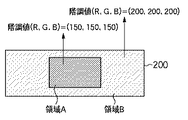
図2は、メモリ部100に格納される固定パターンの画像データの一例を示す図である。固定パターンの画像データ200は、後述する”スクロールパターン”および”サンプル画像”の基準となる基準パターン画像である。ここでは説明を簡潔にするために、固定パターンの画像データ200は矩形の画像データであり、2つの異なる階調値を有する領域(領域Aおよび領域B)により構成されるものとして説明する。具体的には、領域Aは、(R,G,B)=(150,150,150)の濃い(暗い)グレーであり、領域Bは、(R,G,B)=(200,200,200)の薄い(明るい)グレーであるとする。なお、赤(R)、緑(G)、青(B)各色は256(8ビット)階調で表されるものとしている。なお、使用環境の違い等で生じる応答速度の変化量が特に大きい階調の組み合わせを固定パターンに含まれる2種類の階調として選択するとよい。
FIG. 2 is a diagram illustrating an example of fixed pattern image data stored in the
なお、以下の説明ではメモリ部100には1種類の画像データ200のみが格納されているものとして説明を行なうが、互いに異なる複数の固定パターンの画像データを格納するよう構成してもよい。また、グレー以外のパターン画像を格納するよう構成してもよい。また、静止画の代わりに動画像をメモリ部100に格納するよう構成してもよい。その場合はスクロール処理部101を設けなくとも良い。
In the following description, it is assumed that only one type of
・スクロールパターン
図3は、スクロール処理部101が出力するスクロールパターンを説明する図である。
Scroll Pattern FIG. 3 is a diagram for explaining a scroll pattern output from the
スクロール処理部101は、メモリ部100から画像データ200を読みだし、表示出力部110に接続された不図示の液晶表示部上を画像データ200がスクロール表示されるよう処理を行なう。ここで、スクロール表示とは、画像を液晶表示部上を所定の方向に所定の速度で移動表示することを示している。なお、スクロール処理部101は、請求項における第1の表示手段に相当する。
The
スクロール処理部101は、例えば、1フレームで16画素ずつ右方向(一方向)にスクロールする場合、メモリ部100から画像データ200をフレーム毎に右方向へ16画素ずつシフトさせて読み出し、その読み出し結果を出力する。そのように制御することにより、濃いグレーの矩形画像(領域A)が薄いグレー(領域B)を背景画像としてフレーム毎に右方向へ16画素ずつスクロール表示されることになる。以下、スクロール処理され得られた動画像を”スクロールパターン”とよぶ。
For example, when scrolling 16 pixels in the right direction (one direction) in one frame, the
OD駆動調整部102は、スクロール処理部101から出力されたスクロールパターンと、フレームメモリ120に一時記憶された1フレーム前のスクロールパターンとの組み合わせに応じて補正量を算出する。そして、算出した補正量と現表示フレームのスクロールパターンの画像信号とを加減算することによってオーバードライブ駆動のための画像信号を生成する。
The OD
なお、前述したように、OD駆動調整部102において最適な補正量が与えられていない場合、フレーム間での階調変化に対して十分な応答速度の改善を行なうことができない。さらに、フレーム間での階調変化の大きい動画像のエッジ部分などに不自然な色付きが生じたり、残像が残った画像が表示されたりする。そのため、画像データ200を右方向へ所定の速度でスクロール処理した際にも同様に、最適な補正量が与えられていない場合は、フレーム間で階調変化が生じる領域、例えば領域Aの右端領域あるいは左端領域付近に色付きが生じたり、残像が生じたりする。
As described above, when the optimum correction amount is not given in the OD
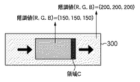
300はスクロールパターンであり、領域Cは、表示フレーム間(つまり、現表示フレームと1つ前の表示フレームとの間)で階調値が変化する領域である。ここでは、(R,G,B)=(200,200,200)から(R,G,B)=(150,150,150)に変化する領域を領域Cとして示している。1フレーム前の階調値(R,G,B)=(200,200,200)と、現フレームの階調値(R,G,B)=(150,150,150)の組み合わせから算出される補正量に基づいてオーバードライブ駆動が行なわれる。そのため、この組み合わせにおいて補正量が最適でない場合に前述の色付きといった不具合が生じる。つまり、領域Cは、OD駆動調整部102において適切な補正量が与えられていない場合に色付きが生じ得る領域を示している。
・サンプル画像
図4は、サンプル画像生成部103が生成する6個のサンプル画像を説明する図である。
Sample Image FIG. 4 is a diagram illustrating six sample images generated by the sample
サンプル画像生成部103は、メモリ部100から画像データ200を読み出し、画像データ200の一部の領域を異なる階調値に置換したサンプル画像を生成する。なお、サンプル画像生成部103は、請求項における第2の表示手段に相当する。図4では、互いに異なる階調値に置換された(a)〜(f)の6個のサンプル画像を生成した例を示している。以下では、サンプル画像の生成手順について述べる。
The sample
まず、サンプル画像生成部103は、メモリ部100から固定パターンの画像データ200を1フレーム期間中に例えば6回読みだす。つまり、サンプル画像は基本的には、基準パターン画像である画像データ200と同一の画像である。なお、ここでは、画像データ200の一部の領域(領域A)のみを読みだすこととする。これは、階調値を置換する領域は前述の領域Cに相当する領域であり、領域Cは領域Aの内部に含まれるからである。
First, the sample
次に、サンプル画像生成部103は、読み出した領域(領域A)の一部(端部)の領域をそれぞれ異なる階調値に置換する。置換を行なう領域(擬似残像領域)は上述の領域Cに相当する領域であり、サンプル画像においては領域Dと呼ぶ。つまり、領域Dの幅は、現フレームと1つ前のフレームとの間で、画素値の変化が生じる領域である。具体的には、液晶表示パネルのリフレッシュレート、および、スクロール速度により決定される。例えば、スクロールパターン300が右方向へ毎フレーム16画素ずつスクロールする動画像である場合、領域Dは領域Aの右端16画素幅程度の矩形領域とすればよい。
Next, the sample
具体的に設定する領域Dの階調値は、どのようなものであってもよいが、使用温度や使用時間などの使用環境から液晶の応答特性の変化度合いをおおよそ予測し、その変化量によって決定する色付き度合いをよく表わす階調値をいくつか設定すればよい。また、領域A、及び領域Bの階調値に近い階調値をいくつか選択し、領域Dにそれぞれ設定してもよい。ここでは一例として、領域Dを、(R,G,B)=(190,190,190)から(R,G,B)=(90,90,90)まで、(R,G,B)=(20,20,20)毎に変化させた互いに異なる6個のグレー画像に置換する。領域Dの階調値を変更する目的は、領域Cを有するスクロールパターン300と類似した画像の候補を、複数の静止パターンとして固定表示することにある。
The gradation value of the region D to be specifically set may be any value, but the degree of change in the response characteristic of the liquid crystal is roughly estimated from the usage environment such as the usage temperature and usage time, and the amount of change It is only necessary to set several gradation values that well represent the degree of coloring to be determined. Further, some gradation values close to the gradation values of the regions A and B may be selected and set in the region D, respectively. Here, as an example, the region D is changed from (R, G, B) = (190, 190, 190) to (R, G, B) = (90, 90, 90), (R, G, B) = Replace with six different gray images which are changed every (20, 20, 20). The purpose of changing the gradation value of the region D is to fix and display image candidates similar to the
スクロールパターン300において、最適な補正量でオーバードライブ駆動が行なわれた場合、領域Cの階調値は、(R,G,B)=(150,150,150)である。しかしながら、最適な補正量でない場合は、例えば階調値が(R,G,B)=(120,120,120)であったり、また例えば色バランスがくずれて(R,G,B)=(120,150,160)であったりする。ただし、領域Cがどのように表示されるかは、使用環境の違い等によって変化するため、予め正確に決定することは困難である。そのため第1実施形態では、スクロールパターン300の領域Cの表示に最も類似した静止パターン(サンプル画像)を、ユーザに選択させることにより、一意に決定するのである。
In the
・設定用ユーザインタフェース(UI)
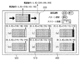
図5は、第1実施形態に係る液晶表示装置の画質調整画面の一例を示す図である。画質調整画面500は、例えば、ユーザが操作部106を操作することにより表示される。例えば、リモコン上の画質設定ボタンを押下することにより画質調整機能が呼び出され、画質調整画面500が表示される。なお、画質調整画面500は合成部105により出力される画像である。また、ユーザは、操作部106を操作することにより、画質調整値の決定指示、使用する固定パターンの画像データの選択指示、スクロール速度、方向の変更指示などを行なう。
-User interface for setting (UI)
FIG. 5 is a diagram illustrating an example of an image quality adjustment screen of the liquid crystal display device according to the first embodiment. The image
図5に示される例では、前述のスクロールパターン300は設定画面の左上領域(第1の領域内)に配置されている。また、複数のサンプルパターンが示された選択画面400は設定画面の下部領域(第2の領域内)に配置されている。さらに、OSD生成部104が生成したボタン類は設定画面の右上領域に配置されている。各部の配置については任意に決定可能であるが、同一画面内に表示することが望ましい。
In the example shown in FIG. 5, the
スクロール処理部101は、ユーザによる固定パターンの画像データの選択指示に基づいて、メモリ部100から読み出す画像データの選択を行なう。ここでは、画像データ200が選択されたものとして説明する。また、スクロール処理部101は、操作部106を介したスクロール速度調節のためのスライダの操作に基づいて、メモリ部100からの画像データ200の読み出しをおよび出力を変更することにより、スクロール速度を所望のものへと変更する。また、画質調整画面500には、図4で示した複数のサンプル画像が選択画面400として配置されている。そして、ユーザからの操作部106を介したカーソル510の移動により、サンプル画像が選択可能なよう構成されている。
The
<装置の動作>
図7は、第1実施形態に係る液晶表示装置の画質調整の処理フローチャートである。なお、以下のフローは例えば、液晶表示装置の不図示のCPUが画質調整プログラムを実行することにより実現される。
<Operation of the device>
FIG. 7 is a process flowchart of image quality adjustment of the liquid crystal display device according to the first embodiment. In addition, the following flow is implement | achieved when CPU not shown of a liquid crystal display device performs an image quality adjustment program, for example.
ステップS11では、操作部106を介してユーザから画質調整開始の指示が行なわれたか否かを判定する。画質調整開始の指示が行なわれた場合はS12に進む。
In step S <b> 11, it is determined whether an instruction to start image quality adjustment has been issued from the user via the
ステップS12では、スクロール処理部101は、メモリ部100から画像データ200を読み込みスクロール画像の生成を開始する。また、OD駆動調整部102は、例えば初期設定値(デフォルト値)の補正量を補正テーブルに基づいて設定し、スクロールパターンに対しOD駆動補正の処理を開始する。
In step S12, the
ステップS13では、サンプル画像生成部103は、メモリ部100から画像データ200を読み込み前述のサンプル画像を生成する。
In step S13, the sample
ステップS14では、画質調整画面500を表示する。そして、固定パターンの種類選択指示、スクロール速度、方向の変更指示の設定をユーザから受け付ける。このとき、例えば、選択画面400には、(a)〜(f)の6個のサンプル画像の領域Dに、それぞれ以下の階調値を設定する。
In step S14, the image
(a):(R,G,B)=(190,190,190)
(b):(R,G,B)=(170,170,170)
(c):(R,G,B)=(150,150,150)
(d):(R,G,B)=(130,130,130)
(e):(R,G,B)=(110,110,110)
(f):(R,G,B)=(90,90,90)
ステップS15では、サンプル画像の選択指示がユーザから行なわれたか否かを判定する。つまり、スクロールパターン300と最も類似したサンプル画像の選択を操作部106を介してユーザから受け付けたか否かを判定する。ユーザから選択指示が行なわれた場合はステップS13へ戻り、前回より細かい階調値の刻みになるよう(a)〜(f)の6個のパターンの階調値を変更する。また、ユーザから選択指示が行なわれなかった場合はステップS16へ進む。
(A): (R, G, B) = (190, 190, 190)
(B): (R, G, B) = (170, 170, 170)
(C): (R, G, B) = (150, 150, 150)
(D): (R, G, B) = (130, 130, 130)
(E): (R, G, B) = (110, 110, 110)
(F): (R, G, B) = (90, 90, 90)
In step S15, it is determined whether a sample image selection instruction has been issued by the user. That is, it is determined whether the selection of the sample image most similar to the
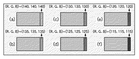
例えば、ステップ(d)のサンプル画像の選択を受け付けた場合、(d)の階調値(R,G,B)=(130,130,130)を中心として、図6に示すように、
(a):(R,G,B)=(140,140,140)
(b):(R,G,B)=(135,135,135)
(c):(R,G,B)=(130,130,130)
(d):(R,G,B)=(125,125,125)
(e):(R,G,B)=(120,120,120)
(f):(R,G,B)=(115,115,115)
とするとよい。そして、再度、サンプル画像の選択指示を受け付ける。以下では、図6(e)のサンプル画像の選択を受け付けたとして説明する。つまり、スクロールパターン300の色付き程度は(R,G,B)=(120,120,120)であると決定される。
For example, when the selection of the sample image in step (d) is received, as shown in FIG. 6, centering on the gradation value (R, G, B) = (130, 130, 130) in (d),
(A): (R, G, B) = (140, 140, 140)
(B): (R, G, B) = (135, 135, 135)
(C): (R, G, B) = (130, 130, 130)
(D): (R, G, B) = (125, 125, 125)
(E): (R, G, B) = (120, 120, 120)
(F): (R, G, B) = (115, 115, 115)
It is good to do. Then, a sample image selection instruction is accepted again. In the following description, it is assumed that the selection of the sample image in FIG. That is, the coloring degree of the
ステップS16では、画質調整決定指示が行なわれたか否かの判断をする。具体的には、画質調整画面500の”決定”ボタンが押下されたか否かを判定する。画質調整決定指示が行なわれた場合は、サンプル画像生成部103はOD駆動調整部102に決定した階調値を送信し、OD駆動調整部102は送信された階調値に基づいて、オーバードライブ駆動の調整値を変更(更新)する。
In step S16, it is determined whether or not an image quality adjustment determination instruction has been performed. Specifically, it is determined whether or not the “Determine” button on the image
オーバードライブ駆動の調整値を変更(更新)された時点で新たな調整値に基づいたオーバードライブ駆動が行なわれ、スクロールパターン300に反映される。画質調整決定指示が行なわれない場合はステップS17に進む。
When the adjustment value of overdrive driving is changed (updated), overdrive driving based on the new adjustment value is performed and reflected in the
なお、OD駆動調整部102は、例えば以下の数式に基づいてオーバードライブ駆動の補正量を調整する。
The OD
α’=α+k(In−P)
ただし、
In:現フレームの階調値
In−1: 1フレーム前の階調値
α:InとIn−1との組み合わせから算出されるオーバードライブ駆動の補正量(αは正負の符号情報を含む。In−1>Inの場合はα≦0であり、In−1≦Inの場合はα≧0)
P:サンプル画像生成部103からOD駆動調整部102へ送る階調値(0≦P≦255)
α’:調整後のオーバードライブ駆動の補正量、
k:0以上の係数
である。なお、上述の式を複数の基準色であるR,G,Bそれぞれ個別に適用してもよく、その場合、補正量αもR,G,B固有の補正量を有する。係数 kは固定値としてもよいが、階調値の組み合わせ毎に予めテーブルとして保持していてもよい。
α ′ = α + k (I n −P)
However,
I n : gradation value of the current frame I n-1 : gradation value of one frame before α: correction amount of overdrive driving calculated from a combination of I n and I n-1 (α is positive / negative sign information) for .I n-1> I n including an α ≦ 0, α ≧ 0 in the case of I n-1 ≦ I n)
P: gradation value sent from the sample
α ′: Overdrive drive correction amount after adjustment,
k: a coefficient of 0 or more. Note that the above formula may be applied individually to each of the plurality of reference colors R, G, and B. In this case, the correction amount α also has a correction amount unique to R, G, and B. The coefficient k may be a fixed value, but may be stored in advance as a table for each combination of gradation values.
なお、α’の導出の仕方は上述の式に限定されることは無く、サンプル画像生成部103からOD駆動調整部102に送信される情報(階調値)に基づいて、補正の過多・過小を補償するようなものであれば任意のものでよい。例えば、
α’=α+α・k(In−P)
を使用して補正量を調整しても良い。
Note that the method of deriving α ′ is not limited to the above formula, and based on information (gradation value) transmitted from the sample
α ′ = α + α · k (I n −P)
May be used to adjust the correction amount.
ステップS17では、画質調整終了指示が行なわれたか否かの判断をする。具体的には、画質調整画面500の”終了”ボタンが押下されたか否かを判定する。画質調整終了指示が行なわれた場合はステップS18に進み、終了指示がなされない場合はステップS15に戻る。
In step S17, it is determined whether or not an image quality adjustment end instruction has been issued. Specifically, it is determined whether or not an “end” button on the image
ステップS18では、画質調整画面の表示を消し、画質調整機能を終了する。 In step S18, the image quality adjustment screen is cleared and the image quality adjustment function is terminated.
以上説明したように、第1実施形態に係る液晶表示装置によれば、ユーザは液晶表示装置のオーバードライブ駆動における補正量設定をより簡易に行うことが可能となる。つまり、ユーザは、画質調整画面500に表示されたスクロールパターン300と類似したサンプル画像を選択するだけでよい。そして、液晶表示装置はユーザにより選択されたサンプル画像に基づいて、現在の表示状態を一意に決定することが出来る。そのため、より適したオーバードライブ駆動の補正量をより正確に設定することが可能となる。
As described above, according to the liquid crystal display device according to the first embodiment, the user can more easily set the correction amount in the overdrive drive of the liquid crystal display device. That is, the user only needs to select a sample image similar to the
なお、OD駆動調整部102における調整前後の補正量の差分値に基づいて、他の階調の組み合わせの補正量についても同様に変更してもよい。また、フラッシュメモリなどの書き換え可能な不揮発メモリ上に、ユーザ調整用のテーブルを設けるよう構成してもよい。
Note that, based on the difference value between the correction amounts before and after the adjustment in the OD
(第2実施形態)
本発明に係る表示制御装置の第2実施形態として、液晶表示装置を例に挙げて以下に説明する。第2実施形態では、ユーザから選択指示が行なわれたタイミングで階調値をOD駆動調整部102へ送信しオーバードライブ駆動の補正量を調整する例について説明する。なお、装置構成は、第1実施形態と同様であるので説明は省略する。
(Second Embodiment)
As a second embodiment of the display control device according to the present invention, a liquid crystal display device will be described below as an example. In the second embodiment, an example will be described in which the gradation value is transmitted to the OD
<装置の動作>
図8は、第2実施形態に係る液晶表示装置の画質調整の処理フローチャートである。なお、以下のフローは例えば、液晶表示装置の不図示のCPUが画質調整プログラムを実行することにより実現される。なお、ステップS21からステップS24までの処理は、第1実施形態におけるステップS11からステップS14までの処理と同様である。
<Operation of the device>
FIG. 8 is a process flowchart of image quality adjustment of the liquid crystal display device according to the second embodiment. In addition, the following flow is implement | achieved when CPU not shown of a liquid crystal display device performs an image quality adjustment program, for example. Note that the processing from step S21 to step S24 is the same as the processing from step S11 to step S14 in the first embodiment.
ステップS25では、サンプル画像の選択指示がユーザから行なわれたか否かを判定する。つまり、スクロールパターン300と最も類似したサンプル画像の選択を操作部106を介してユーザから受け付けたか否かを判定する。ユーザから選択指示が行なわれた場合は、サンプル画像生成部103はOD駆動調整部102に選択した階調値を送信し、OD駆動調整部102は送信された階調値に基づいて、オーバードライブ駆動の調整値を変更(更新)する。ユーザから選択指示が行なわれない場合は、画質調整終了指示があるか否かの判断をする(ステップS26)。そして、画質調整終了指示が行なわれた場合は、画質調整処理を終了する(ステップS27)。
In step S25, it is determined whether a sample image selection instruction has been issued by the user. That is, it is determined whether the selection of the sample image most similar to the
以上説明したように、第2実施形態に係る液晶表示装置によれば、第1実施形態と同様、ユーザは液晶表示装置のオーバードライブ駆動における補正量設定をより簡易に行うことが可能となる。さらに、サンプル画像の選択によりオーバードライブ駆動の調整値が逐次更新され、表示されるスクロールパターンに反映される。そのため、ユーザはより正確にスクロールパターン300と最も類似したサンプル画像の選択を行なうことができる。
As described above, according to the liquid crystal display device according to the second embodiment, similarly to the first embodiment, the user can more easily set the correction amount in the overdrive drive of the liquid crystal display device. Further, the overdrive drive adjustment value is sequentially updated by selecting the sample image and reflected in the displayed scroll pattern. Therefore, the user can select the sample image most similar to the
(変形例1)
変形例1では、第1実施形態で説明したサンプル画像の代わりに有彩色のサンプル画像を生成する例について説明する。
(Modification 1)
In
画質調整画面500に含まれる選択画面400に表示するサンプル画像を、例えば、
(a):(R,G,B)=(180,140,140)
(b):(R,G,B)=(150,170,150)
のように、(a)赤系統の色付きのパターンおよび(b)緑系統の色付きパターンとしてもよい。その場合、もし(a)が選択された場合は、スクロールパターン300の色付き程度が赤っぽいと判定され、次の更新された選択画面400に表示するパターンを、(G,B)の階調値は変更せず、Rの階調値のみを変更したものを6種類用意すればよい。
Sample images to be displayed on the
(A): (R, G, B) = (180, 140, 140)
(B): (R, G, B) = (150, 170, 150)
As described above, (a) a red-colored pattern and (b) a green-colored pattern may be used. In that case, if (a) is selected, it is determined that the color of the
(変形例2)
変形例2では、画質調整画面500に調整用のスライダを設け、ユーザが直接、OD駆動調整部102における調整量を変更可能に構成する。なお、装置構成および動作は、第1実施形態とほぼ同様であるので説明は省略する。
(Modification 2)
In the second modification, an adjustment slider is provided on the image
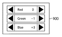
図9は、変形例2に係る液晶表示装置の画質調整画面に含まれる調整用スライダ900を示す図である。
FIG. 9 is a diagram showing an
調整用スライダ900は、赤、緑、青の補正量をそれぞれ個別に直接調整するためのUIである。例えば、第1の実施形態、及び第2の実施形態に記載の処理フローで調整した後に、調整用スライダ900を介して補正量を微調整することによりさらに精度の高い補正量の調整が可能となる。
The
(変形例3)
変形例3では、画質調整画面500に調整用のスライダを設け、ユーザが直接、OD駆動調整部102における調整量を変更可能に構成する。なお、装置構成および動作は、第1実施形態とほぼ同様であるので説明は省略する。
(Modification 3)
In the third modification, an adjustment slider is provided on the image
調整用スライダ900は、赤、緑、青の補正量をそれぞれ個別に直接調整するための画質調整画面500のUIである。また、画質調整画面500の選択画面400には、サンプル画像が1つ表示される。ただし、調整用スライダ900を操作することにより、動的に領域Dの階調値が変化するよう構成されている。
The
つまり、ユーザは、スクロールパターン300の色付きと等しくなるように調整用スライダ900を操作する。そしてユーザは等しくなったと判断した時点で、画質調整決定指示を行なう。画質調整決定指示を受けた後、OD駆動調整部102は、ユーザの設定した階調値に基づいて、第1実施形態で示した数式の基づいてオーバードライブ駆動の補正量を調整する。
That is, the user operates the
このようなUIとして構成することで、例えば、表示画面が小さく、選択画面400に複数のパターンを表示するのが困難な場合などにも適用することが出来る。
By configuring such a UI, for example, the present invention can be applied to a case where the display screen is small and it is difficult to display a plurality of patterns on the
(他の実施形態)
以上、本発明の実施形態について詳述したが、本発明は、複数の機器から構成されるシステムに適用しても良いし、また、一つの機器からなる装置に適用しても良い。
(Other embodiments)
Although the embodiments of the present invention have been described in detail above, the present invention may be applied to a system constituted by a plurality of devices or may be applied to an apparatus constituted by one device.
なお、本発明は、前述した実施形態の機能を実現するプログラムを、システム或いは装置に直接或いは遠隔から供給し、そのシステム或いは装置が、供給されたプログラムコードを読み出して実行することによっても達成される。従って、本発明の機能処理をコンピュータで実現するために、コンピュータにインストールされるプログラムコード自体も本発明の技術的範囲に含まれる。 The present invention can also be achieved by supplying a program that realizes the functions of the above-described embodiments directly or remotely to a system or apparatus, and the system or apparatus reads and executes the supplied program code. The Accordingly, the program code itself installed in the computer in order to realize the functional processing of the present invention by the computer is also included in the technical scope of the present invention.
その場合、プログラムの機能を有していれば、オブジェクトコード、インタプリタにより実行されるプログラム、OSに供給するスクリプトデータ等、プログラムの形態を問わない。 In this case, the program may be in any form as long as it has a program function, such as an object code, a program executed by an interpreter, or script data supplied to the OS.
プログラムを供給するための記録媒体としては、例えば、フロッピー(登録商標)ディスク、ハードディスク、光ディスク(CD、DVD)、光磁気ディスク、磁気テープ、不揮発性のメモリカード、ROMなどがある。 Examples of the recording medium for supplying the program include a floppy (registered trademark) disk, a hard disk, an optical disk (CD, DVD), a magneto-optical disk, a magnetic tape, a nonvolatile memory card, and a ROM.
さらに、記録媒体から読み出されたプログラムが、コンピュータに挿入された機能拡張ボードやコンピュータに接続された機能拡張ユニットに備わるメモリに書き込まれる。その後、そのプログラムの指示に基づき、その機能拡張ボードや機能拡張ユニットに備わるCPUなどが実際の処理の一部または全部を行い、その処理によっても前述した実施形態の機能が実現される。 Further, the program read from the recording medium is written in a memory provided in a function expansion board inserted into the computer or a function expansion unit connected to the computer. Thereafter, the CPU of the function expansion board or function expansion unit performs part or all of the actual processing based on the instructions of the program, and the functions of the above-described embodiments are realized by the processing.
100 メモリ部
101 スクロール処理部
102 OD駆動調整部
103 サンプル画像生成部
104 OSD生成部
105 合成部
106 操作部
110 表示出力部
120 フレームメモリ
200 固定パターンの画像データ
300 スクロールパターン
400 選択画面
500 画質調整画面
510 カーソル
900 調整用スライダ
1000 オーバードライブ補正処理部
1001 補正量決定部
1002 補正テーブル
1003 補正量付加部
DESCRIPTION OF
Claims (5)
予め設定された基準パターン画像を、前記液晶表示装置の第1の領域内で一方向に繰り返しスクロール表示させる第1の表示制御手段と、
前記基準パターン画像と同一形状の複数のサンプル画像であって、各サンプル画像における前記スクロールの方向の端部が互いに異なる擬似残像領域を有する前記複数のサンプル画像を、前記液晶表示装置の第2の領域内に固定表示させる第2の表示制御手段と、
前記第2の領域内に固定表示された前記複数のサンプル画像から1つのサンプル画像をユーザから選択受付する選択受付手段と、
前記選択受付されたサンプル画像の前記擬似残像領域の画素値と前記基準パターン画像の前記擬似残像領域に対応する領域の画素値との差分に基づいて、前記オーバードライブ駆動用のパラメータを決定する決定手段と、
を備えることを特徴とする表示制御装置。 A display control device for determining parameters for overdrive driving of a liquid crystal display device,
The preset reference pattern image, and the first of the first display control means causes repeated scroll display in the first direction in the region of the liquid crystal display device,
A plurality of sample images having the same shape as the reference pattern image, wherein the plurality of sample images having pseudo afterimage areas whose end portions in the scroll direction are different from each other are displayed on the second liquid crystal display device. Second display control means for fixed display in the area;
Selection receiving means for selecting and receiving one sample image from the plurality of sample images fixedly displayed in the second region;
Determining said selecting based on the difference between the reception has been said pixel value of the pseudo afterimage region corresponding to the region of the pseudo afterimage region of the pixel value and the reference pattern image of sample images, to determine the parameters for driving the overdrive Means,
A display control apparatus comprising:
予め設定された基準パターン画像を、前記液晶表示装置の第1の領域内で一方向に繰り返しスクロール表示させる第1の表示制御手段と、
前記基準パターン画像と同一形状のサンプル画像であって、該サンプル画像における前記スクロールの方向の端部が擬似残像領域を有する前記サンプル画像を、前記液晶表示装置の第2の領域内に固定表示させる第2の表示制御手段と、
前記擬似残像領域の画素値の調整を、操作部を介してユーザから受け付ける調整受付手段と、
前記調整された前記擬似残像領域の画素値と前記基準パターン画像の前記擬似残像領域に対応する領域の画素値との差分に基づいて、前記オーバードライブ駆動用のパラメータを決定する決定手段と、
を備えることを特徴とする表示制御装置。 A display control device for determining parameters for overdrive driving of a liquid crystal display device,
The preset reference pattern image, and the first of the first display control means causes repeated scroll display in the first direction in the region of the liquid crystal display device,
A sample image of the reference pattern image and the same shape, the sample image end in the direction of the scroll in the sample image has a pseudo-afterimage region, fixed display in a second region of the liquid crystal display device Second display control means for causing
Adjustment accepting means for accepting adjustment of the pixel value of the pseudo afterimage area from the user via the operation unit ;
A determination unit based on a difference between pixel values of a region corresponding to the pseudo-afterimage region of the reference pattern image and the pixel value before Symbol pseudo afterimage region said adjusted to determine the parameters for the overdriving,
A display control apparatus comprising:
第1の表示制御手段が、予め設定された基準パターン画像を、前記液晶表示装置の第1の領域内で一方向に繰り返しスクロール表示させる第1の表示制御工程と、
第2の表示制御手段が、前記基準パターン画像と同一形状の複数のサンプル画像であって、各サンプル画像における前記スクロールの方向の端部が互いに異なる擬似残像領域を有する前記複数のサンプル画像を、前記液晶表示装置の第2の領域内に固定表示させる第2の表示制御工程と、
選択受付手段が、前記第2の領域内に固定表示された前記複数のサンプル画像から1つのサンプル画像をユーザから選択受付する選択受付工程と、
決定手段が、前記選択受付されたサンプル画像の前記擬似残像領域の画素値と前記基準パターン画像の前記擬似残像領域に対応する領域の画素値との差分に基づいて、前記オーバードライブ駆動用のパラメータを決定する決定工程と、
を含むことを特徴とする決定方法。 A method for determining parameters used when overdriving a liquid crystal display device,
First display control means, a preset reference pattern image, the first of the first display control step causes repeated scroll display in the first direction in the region of the liquid crystal display device,
The second display control means is a plurality of sample images having the same shape as the reference pattern image, and the plurality of sample images having pseudo afterimage regions having different end portions in the scroll direction in each sample image, A second display control step for fixed display in the second region of the liquid crystal display device;
A selection receiving step in which a selection receiving unit selects and receives one sample image from the plurality of sample images fixedly displayed in the second region;
The determining unit is configured to determine the overdrive driving parameter based on a difference between a pixel value of the pseudo afterimage area of the selected and accepted sample image and a pixel value of an area corresponding to the pseudo afterimage area of the reference pattern image. A determination step for determining
A determination method characterized by comprising :
Priority Applications (2)
| Application Number | Priority Date | Filing Date | Title |
|---|---|---|---|
| JP2008140035A JP5215733B2 (en) | 2008-05-28 | 2008-05-28 | Display control apparatus and overdrive drive parameter determination method |
| US12/463,639 US8519927B2 (en) | 2008-05-28 | 2009-05-11 | Display control apparatus and method of determining driving parameter for overdrive |
Applications Claiming Priority (1)
| Application Number | Priority Date | Filing Date | Title |
|---|---|---|---|
| JP2008140035A JP5215733B2 (en) | 2008-05-28 | 2008-05-28 | Display control apparatus and overdrive drive parameter determination method |
Publications (3)
| Publication Number | Publication Date |
|---|---|
| JP2009288455A JP2009288455A (en) | 2009-12-10 |
| JP2009288455A5 JP2009288455A5 (en) | 2011-07-07 |
| JP5215733B2 true JP5215733B2 (en) | 2013-06-19 |
Family
ID=41379239
Family Applications (1)
| Application Number | Title | Priority Date | Filing Date |
|---|---|---|---|
| JP2008140035A Expired - Fee Related JP5215733B2 (en) | 2008-05-28 | 2008-05-28 | Display control apparatus and overdrive drive parameter determination method |
Country Status (2)
| Country | Link |
|---|---|
| US (1) | US8519927B2 (en) |
| JP (1) | JP5215733B2 (en) |
Families Citing this family (10)
| Publication number | Priority date | Publication date | Assignee | Title |
|---|---|---|---|---|
| CN102194397B (en) * | 2010-03-11 | 2016-06-01 | 瑞昱半导体股份有限公司 | Application overdrive controller and control method of overdriving thereof on a display panel |
| TWI451250B (en) * | 2011-03-28 | 2014-09-01 | Phison Electronics Corp | Memory configuring method, memory controller and memory storage apparatus |
| TWI454908B (en) * | 2011-03-28 | 2014-10-01 | Phison Electronics Corp | Memory configuring method, memory controller and memory storage apparatus |
| JP2013003406A (en) * | 2011-06-17 | 2013-01-07 | Kyocera Corp | Electronic device |
| US20150084996A1 (en) * | 2012-04-25 | 2015-03-26 | Sharp Kabushiki Kaisha | Display control circuit, liquid crystal display device provided therewith, and display control method |
| TWI476754B (en) * | 2013-06-25 | 2015-03-11 | Mstar Semiconductor Inc | Correcting system and correcting method for display device |
| KR102471398B1 (en) * | 2017-10-23 | 2022-11-29 | 삼성디스플레이 주식회사 | Display device and method of driving the same |
| CN109215596B (en) * | 2018-10-12 | 2020-04-28 | 惠州市华星光电技术有限公司 | Method and device for automatically adjusting overdrive voltage and display panel |
| CN111554246B (en) * | 2020-05-22 | 2022-04-26 | Tcl华星光电技术有限公司 | Liquid crystal display panel overdrive method and device, display panel and display device |
| EP4327320A1 (en) * | 2021-04-20 | 2024-02-28 | Qualcomm Incorporated | Per layer adaptive over-drive |
Family Cites Families (30)
| Publication number | Priority date | Publication date | Assignee | Title |
|---|---|---|---|---|
| US5945985A (en) * | 1992-10-27 | 1999-08-31 | Technology International, Inc. | Information system for interactive access to geographic information |
| US5583560A (en) * | 1993-06-22 | 1996-12-10 | Apple Computer, Inc. | Method and apparatus for audio-visual interface for the selective display of listing information on a display |
| JPH09305152A (en) * | 1996-05-16 | 1997-11-28 | Brother Ind Ltd | Deciding method for black point of display and deciding |
| JP3305240B2 (en) | 1997-10-23 | 2002-07-22 | キヤノン株式会社 | Liquid crystal display panel driving device and driving method |
| US6100886A (en) * | 1998-02-18 | 2000-08-08 | Tatung Co., Ltd. | Help service function control device added to a multi-channel monitor of a personal computer |
| JPH11298795A (en) * | 1998-04-14 | 1999-10-29 | Sony Corp | Control signal generating circuit |
| US6278433B2 (en) * | 1998-07-31 | 2001-08-21 | Sony Corporation | Method and apparatus for setting up a monitor |
| JP4306127B2 (en) * | 1998-11-30 | 2009-07-29 | ソニー株式会社 | Information providing apparatus and information providing method |
| WO2000033570A1 (en) * | 1998-11-30 | 2000-06-08 | Sony Corporation | Information providing device and method |
| US6686953B1 (en) * | 2000-03-01 | 2004-02-03 | Joseph Holmes | Visual calibration target set method |
| TW513598B (en) | 2000-03-29 | 2002-12-11 | Sharp Kk | Liquid crystal display device |
| JP3713208B2 (en) | 2000-03-29 | 2005-11-09 | シャープ株式会社 | Liquid crystal display device |
| EP1364537A4 (en) * | 2000-12-28 | 2005-12-14 | Thomson Licensing | On screen display as diagnostic aid |
| TW200303001A (en) | 2001-11-09 | 2003-08-16 | Sharp Kk | Liquid crystal display device |
| TW575864B (en) | 2001-11-09 | 2004-02-11 | Sharp Kk | Liquid crystal display device |
| US7180539B2 (en) * | 2002-07-18 | 2007-02-20 | Tektronix, Inc. | Luminance qualified vector display |
| JP2005070799A (en) | 2002-09-04 | 2005-03-17 | Sharp Corp | Liquid crystal display device |
| JP3916544B2 (en) * | 2002-10-22 | 2007-05-16 | シャープ株式会社 | Response characteristic evaluation pattern display method for liquid crystal display panel and response characteristic evaluation pattern generation apparatus thereof |
| JP4425643B2 (en) * | 2003-02-10 | 2010-03-03 | シャープ株式会社 | Evaluation apparatus for liquid crystal display device, liquid crystal display device, and evaluation method for liquid crystal display device |
| JP4815096B2 (en) * | 2003-06-12 | 2011-11-16 | 株式会社日立製作所 | Information search / playback apparatus and display method thereof |
| US20050073530A1 (en) * | 2003-10-03 | 2005-04-07 | Jay Kapur | System and method for display calibration |
| US20050125179A1 (en) * | 2003-12-05 | 2005-06-09 | Genesis Microchip Inc. | LCD overdrive auto-calibration apparatus and method |
| JP2005292804A (en) * | 2004-03-10 | 2005-10-20 | Canon Inc | Control device and image display device |
| JP2006243325A (en) | 2005-03-03 | 2006-09-14 | Matsushita Electric Ind Co Ltd | Liquid crystal display device |
| JP2006325122A (en) * | 2005-05-20 | 2006-11-30 | Otsuka Denshi Co Ltd | Moving picture display performance determining method, inspection screen, and moving picture display performance determining apparatus |
| JP4815927B2 (en) * | 2005-07-27 | 2011-11-16 | ソニー株式会社 | DISPLAY DEVICE, MENU DISPLAY METHOD, MENU DISPLAY METHOD PROGRAM, AND RECORDING MEDIUM CONTAINING MENU DISPLAY METHOD PROGRAM |
| US7428647B2 (en) * | 2005-10-14 | 2008-09-23 | Dell Products L.P. | System and method for managing information handling system display response time |
| TW200727221A (en) * | 2006-01-03 | 2007-07-16 | Mstar Semiconductor Inc | Driving apparatus of liquid crystal display apparatus and its driving method |
| JP2007199470A (en) * | 2006-01-27 | 2007-08-09 | Nec Electronics Corp | Liquid crystal panel driving device and liquid crystal display |
| JP5110862B2 (en) | 2006-12-01 | 2012-12-26 | キヤノン株式会社 | Liquid crystal display device and control method thereof, computer program, and storage medium |
-
2008
- 2008-05-28 JP JP2008140035A patent/JP5215733B2/en not_active Expired - Fee Related
-
2009
- 2009-05-11 US US12/463,639 patent/US8519927B2/en not_active Expired - Fee Related
Also Published As
| Publication number | Publication date |
|---|---|
| US20090295827A1 (en) | 2009-12-03 |
| JP2009288455A (en) | 2009-12-10 |
| US8519927B2 (en) | 2013-08-27 |
Similar Documents
| Publication | Publication Date | Title |
|---|---|---|
| JP5215733B2 (en) | Display control apparatus and overdrive drive parameter determination method | |
| JP4828425B2 (en) | Driving method of liquid crystal display device, driving device, program and recording medium thereof, and liquid crystal display device | |
| JP4567052B2 (en) | Display device, liquid crystal monitor, liquid crystal television receiver and display method | |
| US7924298B2 (en) | Display control method, driving device for display device, display device, program, and storage medium | |
| JP5031553B2 (en) | Display device, liquid crystal monitor, liquid crystal television receiver and display method | |
| JP5337439B2 (en) | Method and apparatus for driving liquid crystal display device | |
| KR101235806B1 (en) | Driving apparatus of liquid crystal display and driving method thereof | |
| CN100477733C (en) | Display apparatus | |
| JP2006323130A (en) | Image display device and image display method | |
| CN107408366B (en) | Test patterns for motion induced chroma shifts | |
| US20020057249A1 (en) | Liquid crystal display device | |
| KR100701515B1 (en) | Method of driving a display, display, and computer-readable medium on which computer program for the same is recorded | |
| JPWO2009081602A1 (en) | Display device | |
| US20120249619A1 (en) | Display device | |
| JP2005340954A (en) | Information processor and method for controlling display | |
| JP2010113240A (en) | Liquid crystal display device | |
| JP2009058684A (en) | Liquid crystal display device | |
| US20170092217A1 (en) | Video display apparatus, information processing method, and storage medium | |
| JP5132081B2 (en) | Display device | |
| JP2003308057A (en) | Color display device | |
| JP2004348151A (en) | Liquid crystal display method | |
| JP2009116200A (en) | Video display apparatus, video processing method and computer program | |
| JP2015022123A (en) | Display device, control method of display device, and program | |
| US8743289B2 (en) | Image display apparatus and image display method | |
| WO2024000181A1 (en) | Solid-state imaging device having tunable conversion gain, driving method, and electronic device |
Legal Events
| Date | Code | Title | Description |
|---|---|---|---|
| A521 | Request for written amendment filed |
Free format text: JAPANESE INTERMEDIATE CODE: A523 Effective date: 20110520 |
|
| A621 | Written request for application examination |
Free format text: JAPANESE INTERMEDIATE CODE: A621 Effective date: 20110520 |
|
| A977 | Report on retrieval |
Free format text: JAPANESE INTERMEDIATE CODE: A971007 Effective date: 20130121 |
|
| TRDD | Decision of grant or rejection written | ||
| A01 | Written decision to grant a patent or to grant a registration (utility model) |
Free format text: JAPANESE INTERMEDIATE CODE: A01 Effective date: 20130201 |
|
| A61 | First payment of annual fees (during grant procedure) |
Free format text: JAPANESE INTERMEDIATE CODE: A61 Effective date: 20130301 |
|
| R151 | Written notification of patent or utility model registration |
Ref document number: 5215733 Country of ref document: JP Free format text: JAPANESE INTERMEDIATE CODE: R151 |
|
| FPAY | Renewal fee payment (event date is renewal date of database) |
Free format text: PAYMENT UNTIL: 20160308 Year of fee payment: 3 |
|
| LAPS | Cancellation because of no payment of annual fees |