JP2015022123A - Display device, control method of display device, and program - Google Patents
Display device, control method of display device, and program Download PDFInfo
- Publication number
- JP2015022123A JP2015022123A JP2013149751A JP2013149751A JP2015022123A JP 2015022123 A JP2015022123 A JP 2015022123A JP 2013149751 A JP2013149751 A JP 2013149751A JP 2013149751 A JP2013149751 A JP 2013149751A JP 2015022123 A JP2015022123 A JP 2015022123A
- Authority
- JP
- Japan
- Prior art keywords
- image data
- luminance
- display device
- image
- brightness
- Prior art date
- Legal status (The legal status is an assumption and is not a legal conclusion. Google has not performed a legal analysis and makes no representation as to the accuracy of the status listed.)
- Pending
Links
Images


Abstract
Description
本発明は、表示装置、表示装置の制御方法、及び、プログラムに関する。 The present invention relates to a display device, a display device control method, and a program.
従来、液晶表示装置において、複数の光源を有するバックライトを用い、画像データの輝度を表す特徴量に応じて各光源の発光輝度を個別に制御する技術が知られている。このような技術では、例えば、暗い画像の領域(暗部画像領域)に対応する光源の発光輝度が低い値に制御され、明るい画像の領域(明部画像領域)に対応する光源の発光輝度が高い値に制御される。それにより、暗部画像領域の黒浮き量を低減して暗部画像領域の視認性を改善することができるとともに、表示画像(画面に表示された画像)のコントラストを高めることができる。このような技術は、例えば、特許文献1に開示されている。 Conventionally, in a liquid crystal display device, a technique is known in which a backlight having a plurality of light sources is used and the light emission luminance of each light source is individually controlled in accordance with a feature amount representing the luminance of image data. In such a technique, for example, the light emission luminance of the light source corresponding to the dark image region (dark portion image region) is controlled to a low value, and the light emission luminance of the light source corresponding to the bright image region (bright portion image region) is high. Controlled by value. Accordingly, it is possible to improve the visibility of the dark image area by reducing the amount of black floating in the dark image area, and to increase the contrast of the display image (image displayed on the screen). Such a technique is disclosed in Patent Document 1, for example.
一方、ユーザ操作に応じて表示画像の見やすさ(明るさ)を調整する技術が知られている。このような技術では、例えば、ユーザによって指示されたゲイン値(画素間で共通のゲイン値)が全ての画素値(画素データ)に乗算される。それにより、表示画像の明るさをユーザの好みの明るさに調整することができる。このような技術は、例えば、特許文献2に開示されている。 On the other hand, a technique for adjusting the visibility (brightness) of a display image according to a user operation is known. In such a technique, for example, all pixel values (pixel data) are multiplied by a gain value (a gain value common to the pixels) designated by the user. Thereby, the brightness of the display image can be adjusted to the brightness desired by the user. Such a technique is disclosed in Patent Document 2, for example.
液晶表示装置では、画像データの特徴量に応じて各光源の発光輝度を制御することによって、表示画像の黒浮き量を低減し、表示画像のコントラストを高めることが求められる。さらに、液晶表示装置では、ユーザ操作に応じて画像データに画像処理(輝度を高める画像処理)を施すことにより、表示画像の明るさをユーザの好みの明るさに調整することが求められる。
しかしながら、これらを両立させようとすると、以下のような課題が生じてしまう。
ユーザが指示したゲイン値を画素値に乗算したことによって画素値が高められた場合に、画素値の上昇によって特徴量が変化し、特徴量が変化したことによって各光源の発光輝度が高められてしまう。その結果、暗部画像領域の黒浮き量が増加して、暗部画像領域の視認性が低下してしまう。すなわち、従来技術では、暗部画像領域の視認性の向上を意図してユーザがゲイン値を調整したにもかかわらず、当該調整によって各光源の発光輝度が高められて黒浮き量が増加してしまうため、意図した暗部画像領域の視認性改善効果を得ることができない。
In the liquid crystal display device, it is required to reduce the black floating amount of the display image and increase the contrast of the display image by controlling the light emission luminance of each light source according to the feature amount of the image data. Further, in the liquid crystal display device, it is required to adjust the brightness of the display image to the brightness desired by the user by performing image processing (image processing for increasing luminance) on the image data in accordance with a user operation.
However, if both are desired, the following problems will occur.
When the pixel value is increased by multiplying the pixel value by the gain value specified by the user, the feature amount changes as the pixel value increases, and the emission luminance of each light source is increased as the feature amount changes. End up. As a result, the amount of black floating in the dark area image area increases, and the visibility of the dark area image area decreases. That is, in the prior art, even though the user has adjusted the gain value with the intention of improving the visibility of the dark image area, the light emission luminance of each light source is increased by the adjustment, and the black floating amount increases. Therefore, the effect of improving the visibility of the intended dark part image area cannot be obtained.
本発明は、黒浮き量の増加を抑制しながら表示画像の明るさを調整することのできる技術を提供することを目的とする。 An object of the present invention is to provide a technique capable of adjusting the brightness of a display image while suppressing an increase in the amount of black floating.
本発明の第1の態様は、
個別に発光輝度を制御可能な複数の光源を有する発光手段と、
入力された画像データに基づいて前記発光手段からの光を変調することにより、画面上に画像を表示する表示手段と、
画像データに対し輝度を調整する輝度調整処理を施し、前記輝度調整処理が施された後の画像データを前記表示手段に出力する画像処理手段と、
前記複数の光源に対応する画面上の複数の領域のそれぞれについて、前記輝度調整処理が施された後の画像データに比べて前記輝度調整処理が施される前の画像データに近い画像データから、その領域における画像データの輝度を表す特徴量を取得する取得手段と、
前記取得手段で取得された特徴量に基づいて、各光源の発光輝度を制御する制御手段と、
を有することを特徴とする表示装置である。
The first aspect of the present invention is:
A light emitting means having a plurality of light sources capable of individually controlling the light emission brightness;
Display means for displaying an image on a screen by modulating light from the light emitting means based on input image data;
Image processing means for performing brightness adjustment processing for adjusting brightness on the image data, and outputting the image data after the brightness adjustment processing to the display means;
For each of a plurality of areas on the screen corresponding to the plurality of light sources, from image data close to the image data before being subjected to the luminance adjustment processing compared to image data after being subjected to the luminance adjustment processing, Acquisition means for acquiring a feature amount representing the luminance of the image data in the region;
Control means for controlling the light emission luminance of each light source based on the feature amount obtained by the obtaining means;
It is a display device characterized by having.
本発明の第2の態様は、
個別に発光輝度を制御可能な複数の光源を有する発光手段と、
入力された画像データに基づいて前記発光手段からの光を変調することにより、画面上に画像を表示する表示手段と、
を有する表示装置の制御方法であって、
画像データに対し輝度を調整する輝度調整処理を施し、前記輝度調整処理が施された後の画像データを前記表示手段に出力する画像処理ステップと、
前記複数の光源に対応する画面上の複数の領域のそれぞれについて、前記輝度調整処理が施された後の画像データに比べて前記輝度調整処理が施される前の画像データに近い画像データから、その領域における画像データの輝度を表す特徴量を取得する取得ステップと、
前記取得ステップで取得された特徴量に基づいて、各光源の発光輝度を制御する制御ステップと、
を有することを特徴とする表示装置の制御方法である。
The second aspect of the present invention is:
A light emitting means having a plurality of light sources capable of individually controlling the light emission brightness;
Display means for displaying an image on a screen by modulating light from the light emitting means based on input image data;
A display device control method comprising:
An image processing step of performing luminance adjustment processing for adjusting luminance on the image data, and outputting the image data after the luminance adjustment processing to the display unit;
For each of a plurality of areas on the screen corresponding to the plurality of light sources, from image data close to the image data before being subjected to the luminance adjustment processing compared to image data after being subjected to the luminance adjustment processing, An obtaining step for obtaining a feature amount representing luminance of image data in the region;
A control step of controlling the light emission luminance of each light source based on the feature amount acquired in the acquisition step;
A control method for a display device, comprising:
本発明の第3の態様は、上述した表示装置の制御方法の各ステップをコンピュータに実行させることを特徴とするプログラムである。 According to a third aspect of the present invention, there is provided a program that causes a computer to execute each step of the display device control method described above.
本発明によれば、黒浮き量の増加を抑制しながら表示画像の明るさを調整することができる。 According to the present invention, it is possible to adjust the brightness of a display image while suppressing an increase in the amount of black float.
<実施例1>
以下、本発明の実施例1に係る表示装置及びその制御方法について説明する。
なお、本実施例では、表示装置が透過型の液晶表示装置である場合の例を説明するが、表示装置は、透過型の液晶表示装置に限らない。表示装置は、独立した光源を有する表示装置であればよい。例えば、表示装置は、反射型の液晶表示装置であってもよい。また、表示装置は、液晶素子の代わりにMEMS(Micro Electro Mechanical System)シャッターを用いたMEMSシャッター方式ディスプレイであってもよい。
<Example 1>
Hereinafter, a display device and a control method thereof according to Embodiment 1 of the present invention will be described.
In this embodiment, an example in which the display device is a transmissive liquid crystal display device will be described. However, the display device is not limited to a transmissive liquid crystal display device. The display device may be a display device having an independent light source. For example, the display device may be a reflective liquid crystal display device. Further, the display device may be a MEMS shutter system display using a MEMS (Micro Electro Mechanical System) shutter instead of the liquid crystal element.
(全体構成)
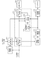
図1は、本実施例に係る液晶表示装置の機能構成の一例を示すブロック図である。図1に示すように、本実施例に係る液晶表示装置は、モード切り替え部101、画像処理部111、特徴量取得部103、目標輝度決定部104、バックライト制御値決定部109、液晶パネル108、バックライト110、などを有する。
(overall structure)
FIG. 1 is a block diagram illustrating an example of a functional configuration of the liquid crystal display device according to the present embodiment. As shown in FIG. 1, the liquid crystal display device according to this embodiment includes a
バックライト110は、個別に発光輝度を制御可能な複数の光源を有する発光部である。光源は、1つ以上の発光部材を有する。発光部材としては、例えば、LED、有機EL素子、冷陰極管、などを用いることができる。バックライト110からの光は、液晶パネル108の背面に照射される。
The
液晶パネル108は、液晶パネル108に入力された画像データに基づいてバックライト110からの光を変調することにより、画面上に画像を表示する表示パネルである。具体的には、液晶パネル108は複数の液晶素子を有しており、液晶パネル108に入力された画像データに基づいて各液晶素子の透過率を制御する。そして、バックライト110からの光が各液晶素子を透過することにより、画面上に画像が表示される。
The
モード切り替え部101は、ユーザから指示された動作モードを設定し、ユーザから指示されたゲイン値(ユーザ指示ゲイン値)を設定する。
そして、モード切り替え部101は、設定されている動作モードに応じて、設定されているユーザ指示ゲイン値を画像処理部111に出力する。具体的には、モード切り替え部101は、設定されている動作モードに応じて、設定されているユーザ指示ゲイン値を、後述する第2ゲイン乗算部102またはゲイン混合部106に出力する。本実施例では、液晶表示装置が、動作モードとして第1のモードまたは第2のモードを設定可能な装置であるものとする。そして、第1のモードが設定されている場合には、モード切り替え部101は、ユーザ指示ゲイン値をゲイン混合部106に出力し、ゲイン値1を第2ゲイン乗算部102に出力する。第2のモードが設定されている場合には、モード切り替え部101は、ユーザ指示ゲイン値を第2ゲイン乗算部102に出力し、ゲイン値1をゲイン混合部106に出力する。以後、モード切り替え部101が第2ゲイン乗算部102に出力するゲイン値をGfと記載し、モード切り替え部101がゲイン混合部106に出力するゲイン値をGbと記載する。
The
Then, the
なお、第1のモードは、表示画像(画面に表示された画像)のコントラストを高めると共に、黒浮き量の増加を抑制しながら表示画像の明るさを調整する動作モードである。第2のモードは、画素間の階調値(画素値)のバランスを崩すことなく表示画像のコントラストを高める動作モードである。
なお、本実施例では、ユーザ操作に応じてユーザ指示ゲイン値と動作モードが設定されるものとしたが、これに限らない。例えば、ユーザ指示ゲイン値と動作モードは、入力画像データの種類や輝度などに応じて自動で設定されてもよい。
なお、液晶表示装置は、第1のモードと第2のモード以外の動作モードを有していてもよい。
Note that the first mode is an operation mode in which the contrast of the display image (image displayed on the screen) is increased and the brightness of the display image is adjusted while suppressing an increase in the amount of black float. The second mode is an operation mode in which the contrast of a display image is increased without breaking the balance of gradation values (pixel values) between pixels.
In this embodiment, the user instruction gain value and the operation mode are set according to the user operation. However, the present invention is not limited to this. For example, the user instruction gain value and the operation mode may be automatically set according to the type and brightness of the input image data.
Note that the liquid crystal display device may have an operation mode other than the first mode and the second mode.
画像処理部111は、画像データに対し輝度を調整する輝度調整処理と、バックライト110が有する光源の発光輝度の変化による画面上の輝度の変化を補償する補償処理とを、画像データに施す。そして、画像処理部111は、輝度調整処理と補償処理が施された後の画像データを液晶パネル108に出力する。
The
本実施例では、輝度調整処理として、設定されているユーザ指示ゲイン値(階調値の上昇率)で画像データの輝度を調整する処理が行われる。具体的には、本実施例では、ユーザ指示ゲイン値を画像データの各画素の階調値に乗算することにより、画像データの輝度
が調整される。
In the present embodiment, as the luminance adjustment processing, processing for adjusting the luminance of the image data with the set user instruction gain value (gradation value increase rate) is performed. Specifically, in this embodiment, the luminance of the image data is adjusted by multiplying the user-indicated gain value by the gradation value of each pixel of the image data.
また、本実施例では、補償処理として、後述する輝度補償ゲイン決定部105で決定された輝度補償ゲイン値で画像データの輝度を調整する処理が行われる。
In the present embodiment, as the compensation process, a process of adjusting the brightness of the image data with the brightness compensation gain value determined by the brightness compensation
図1に示すように、画像処理部111は、第1ゲイン乗算部107、第2ゲイン乗算部102、輝度補償ゲイン決定部105、ゲイン混合部106、などを有する。
As shown in FIG. 1, the
なお、本実施例では、液晶表示装置に入力された画像データ(入力画像データ)に対して輝度調整処理と補償処理が施される例を説明するが、これに限らない。入力画像データに対し所定の画像処理が施され、所定の画像処理が施された後の画像データに対して輝度調整処理と補償処理が施されてもよい。所定の画像処理は、例えば、ぼかし処理、エッジ強調処理、色変換処理、などである。 In this embodiment, an example in which the brightness adjustment process and the compensation process are performed on the image data (input image data) input to the liquid crystal display device will be described. However, the present invention is not limited to this. Predetermined image processing may be performed on the input image data, and brightness adjustment processing and compensation processing may be performed on the image data after the predetermined image processing is performed. The predetermined image processing is, for example, blurring processing, edge enhancement processing, color conversion processing, and the like.
第2ゲイン乗算部102は、モード切り替え部101から入力されたゲイン値Gfを、入力画像データの各画素の階調値に乗算し、ゲイン値Gfが乗算された後の画像データを、第1ゲイン乗算部107と特徴量取得部103に出力する。
上述したように、第1のモードが設定されている場合には、モード切り替え部101から第2ゲイン乗算部102にユーザ指示ゲイン値ではなくゲイン値1が送られる。そのため、第1のモードが設定されている場合には、第2ゲイン乗算部102は、入力画像データ(輝度調整処理が施される前の画像データ)を、第1ゲイン乗算部107と特徴量取得部103に出力する。
また、第2のモードが設定されている場合には、モード切り替え部101から第2ゲイン乗算部102にユーザ指示ゲイン値が送られる。そのため、第2のモードが設定されている場合には、第2ゲイン乗算部102は、ユーザ指示ゲイン値を用いて、入力画像データに対して輝度調整処理を施す。そして、第2ゲイン乗算部102は、輝度調整処理が施された後の画像データを、第1ゲイン乗算部107と特徴量取得部103に出力する。
The second
As described above, when the first mode is set, the
When the second mode is set, the user instruction gain value is sent from the
特徴量取得部103は、バックライト110が有する複数の光源に対応する複数の領域のそれぞれについて、特徴量取得部103に入力された画像データから、その領域における画像データの輝度を表す特徴量を取得する。そして、特徴量取得部103は、取得した特徴量を目標輝度決定部104に出力する。特徴量は、例えば、画素値の代表値(最大値、最小値、最頻値、中間値、平均値、など)やヒストグラム、輝度値の代表値やヒストグラム、などである。
上述したように、第1のモードが設定されている場合には、入力画像データが特徴量取得部103に入力される。そのため、第1のモードが設定されている場合には、入力画像データから特徴量が取得される。
また、第2のモードが設定されている場合には、輝度調整処理が施された後の画像データが特徴量取得部103に入力される。そのため、第2のモードが設定されている場合には、輝度調整処理が施された後の画像データから特徴量が取得される。
For each of a plurality of regions corresponding to a plurality of light sources included in the
As described above, when the first mode is set, the input image data is input to the feature
When the second mode is set, the image data after the brightness adjustment process is input to the feature
なお、本実施例では、複数の光源に対応する複数の領域として、画面の領域を構成する複数の分割領域が設定されるものとする。しかし、光源に対応する領域はこれに限らない。例えば、光源に対応する領域として、他の光源に対応する領域に重なる領域を設定してもよいし、他の光源に対応する領域に接しない領域を設定してもよい。
また、本実施例では、複数の光源に対応する複数の領域として、互いに異なる複数の分割領域が設定されるものとするが、これに限らない。例えば、光源に対応する領域として、他の光源に対応する領域と同じ領域を設定してもよい。
In this embodiment, it is assumed that a plurality of divided areas constituting a screen area are set as a plurality of areas corresponding to a plurality of light sources. However, the area corresponding to the light source is not limited to this. For example, as an area corresponding to a light source, an area overlapping with an area corresponding to another light source may be set, or an area not in contact with an area corresponding to another light source may be set.
In this embodiment, a plurality of different divided areas are set as a plurality of areas corresponding to a plurality of light sources, but the present invention is not limited to this. For example, the same area as that corresponding to another light source may be set as the area corresponding to the light source.
目標輝度決定部104とバックライト制御値決定部109により、特徴量取得部103
で取得された特徴量に基づいて、バックライト110が有する各光源の発光輝度が制御される。
上述したように、第1のモードが設定されている場合には、入力画像データから特徴量が取得される。そのため、第1のモードが設定されている場合には、入力画像データから取得された特徴量に基づいて発光輝度が制御される。
また、第2のモードが設定されている場合には、輝度調整処理が施された後の画像データから特徴量が取得される。そのため、第2のモードが設定されている場合には、輝度調整処理が施された後の画像データから取得された特徴量に基づいて発光輝度が制御される。
A feature
Based on the feature amount acquired in step S1, the light emission luminance of each light source included in the
As described above, when the first mode is set, the feature amount is acquired from the input image data. Therefore, when the first mode is set, the light emission luminance is controlled based on the feature amount acquired from the input image data.
Further, when the second mode is set, the feature amount is acquired from the image data after the luminance adjustment process is performed. Therefore, when the second mode is set, the light emission luminance is controlled based on the feature amount acquired from the image data after the luminance adjustment processing is performed.
目標輝度決定部104は、分割領域毎に、その分割領域に対して取得された特徴量に基づいて、当該領域に対応する光源の目標輝度を決定する。目標輝度は、例えば、特徴量と目標輝度の対応関係を表す関数やテーブルを用いて決定される。本実施例では、暗い画像の領域(暗部画像領域)で明るい画像の領域(明部画像領域)よりも目標輝度が低くなるように、目標輝度が決定される。そして、目標輝度決定部104は、分割領域毎(光源毎)の目標輝度を輝度補償ゲイン決定部105、ゲイン混合部106、及び、バックライト制御値決定部109に出力する。
なお、目標輝度の決定方法は上記方法に限らない。例えば、光源の目標輝度は、当該光源に対応する分割領域の特徴量と、当該光源の周囲の光源に対応する分割領域の特徴量とを用いて決定されてもよい。
For each divided region, the target
The method for determining the target brightness is not limited to the above method. For example, the target luminance of the light source may be determined using the feature amount of the divided region corresponding to the light source and the feature amount of the divided region corresponding to the light sources around the light source.
バックライト制御値決定部109は、バックライト110が有する各光源の発光輝度を目標輝度に制御する。具体的には、バックライト制御値決定部109は、光源毎に、その光源の目標輝度に基づいて、当該光源のバックライト制御値を決定する。バックライト制御値は、例えば、目標輝度とバックライト制御値の対応関係を表す関数やテーブルを用いて決定される。光源へ供給する電圧(または電流)の供給時間(パルス幅)を制御することにより当該光源の発光輝度が制御される場合には、パルス幅を表す値がバックライト制御値として決定される。光源へ供給する電圧(または電流)の値(パルス振幅)を制御することにより当該光源の発光輝度が制御される場合には、パルス振幅を表す値がバックライト制御値として決定される。パルス幅とパルス振幅の両方を制御することにより発光輝度が制御される場合には、パルス幅とパルス振幅の両方を表す値がバックライト制御値として決定される。
そして、バックライト制御値決定部109は、各光源のバックライト制御値をバックライト110に出力する。バックライト110では、各光源がバックライト制御値に応じた発光輝度で発光する。
The backlight control
Then, the backlight control
輝度補償ゲイン決定部105は、分割領域毎(光源毎)の目標輝度に基づいて、各光源の発光輝度を目標輝度に制御した場合のバックライト110からの光の輝度分布(画素位置毎の輝度)を推定する。輝度分布は、例えば、光源からの光の減衰を考慮して推定される。また、光源からの光が他の分割領域へ漏れる場合には、そのような光の漏れを考慮して輝度分布が推定される。
そして、輝度補償ゲイン決定部105は、画素毎に、その画素の位置に対して推定された輝度で所定の基準値を除算した値を、当該画素の輝度補償ゲイン値として決定する。それにより、輝度補償ゲイン値として、光源の発光輝度の変化による画面上の輝度の変化を補償するゲイン値を得ることができる。なお、輝度補償ゲイン値は、推定輝度と輝度補償ゲイン値の対応関係を表す関数を用いて算出されてもよいし、そのような対応関係を表すテーブルを用いて決定されてもよい。
輝度補償ゲイン決定部105は、画素毎の輝度補償ゲイン値をゲイン混合部106に出力する。
なお、本実施例では、画素毎に輝度補償ゲイン値が決定されるものとしたが、これに限
らない。例えば、分割領域毎に、その分割領域の目標輝度を用いて、当該分割領域内の各画素に対して共通の輝度補償ゲイン値が決定されてもよい。具体的には、分割領域毎に、その分割領域の目標輝度で基準値を除算した値が、当該分割領域内の各画素に対する輝度補償ゲイン値として算出されてもよい。
The luminance compensation
Then, the luminance compensation
The luminance compensation
In this embodiment, the luminance compensation gain value is determined for each pixel. However, the present invention is not limited to this. For example, for each divided area, a common luminance compensation gain value may be determined for each pixel in the divided area using the target luminance of the divided area. Specifically, for each divided region, a value obtained by dividing the reference value by the target luminance of the divided region may be calculated as a luminance compensation gain value for each pixel in the divided region.
ゲイン混合部106は、画素毎に、モード切り替え部101から入力されたゲイン値Gbと、輝度補償ゲイン決定部105から入力された輝度補償ゲイン値とを混合した混合ゲイン値を算出する。具体的には、ゲイン値Gbに輝度補償ゲイン値を乗算することによりに、混合ゲイン値が算出される。
上述したように、第1のモードが設定されている場合には、モード切り替え部101からゲイン混合部106にユーザ指示ゲイン値が送られる。そのため、第1のモードが設定されている場合には、混合ゲイン値として、輝度調整処理と補償処理の両方を施すゲイン値が算出される。
また、第2のモードが設定されている場合には、モード切り替え部101からゲイン混合部106にユーザ指示ゲイン値ではなくゲイン値1が送られる。そのため、第2のモードが設定されている場合には、混合ゲイン値として、補償処理を施すゲイン値(輝度補償ゲイン値)が算出される。
The
As described above, when the first mode is set, the user instruction gain value is sent from the
Further, when the second mode is set, the
第1ゲイン乗算部107は、ゲイン混合部106から入力された混合ゲイン値を、第2ゲイン乗算部102から入力された画像データに乗算し、混合ゲイン値が乗算された後の画像データを液晶パネル108に出力する。混合ゲイン値が乗算された後の画像データは、輝度調整処理と補償処理の両方が施された後の画像データである。
上述したように、第1のモードが設定されている場合には、ゲイン混合部106から輝度調整処理と補償処理の両方を施す混合ゲイン値が送られ、第2ゲイン乗算部102から入力画像データが送られる。そのため、第1のモードが設定されている場合には、第1ゲイン乗算部107は、入力画像データに輝度調整処理と補償処理の両方を施す。
また、第2のモードが設定されている場合には、ゲイン混合部106から補償処理を施す混合ゲイン値が送られ、第2ゲイン乗算部102から輝度調整処理が施された後の画像データが送られる。そのため、第2のモードが設定されている場合には、第1ゲイン乗算部107は、輝度調整処理が施された後の画像データに補償処理を施す。
The first
As described above, when the first mode is set, the
Further, when the second mode is set, the mixed gain value to which compensation processing is performed is sent from the
なお、ゲイン混合部106では、混合ゲインを階調値に乗算しても階調値が上限値(階調上限値)を超えないように、画像データの取り得る階調値毎にユーザ指示ゲイン値の上限値(ユーザ指示ゲイン上限値)が決定される。そして、ゲイン混合部106では、ユーザ指示ゲイン値がユーザ指示ゲイン上限値を超えていない画素については、取得されたユーザ指示ゲイン値が使用される。また、ユーザ指示ゲイン値がユーザ指示ゲイン上限値を超えている画素については、ユーザ指示ゲイン値としてユーザ指示ゲイン上限値が使用される。なお、ユーザ指示ゲイン値がユーザ指示ゲイン上限値を超えている画素については、ユーザ指示ゲイン値として、ユーザ指示ゲイン上限値より小さい値が使用されてもよい。
In the
階調値に対応するユーザ指示ゲイン上限値の決定方法を以下に示す。
階調値は、通常、有限ビット長のデジタルデータで表現される。そのため、階調値には上限値(階調上限値)が存在する。この階調上限値をある階調値で除算した値が、当該階調値に乗算可能なゲイン値の上限値(ゲイン上限値)である。ゲイン上限値は階調値毎に決まる。そして、ゲイン上限値を超えるようなゲイン値を階調値に乗算すると、階調値が飽和し、階調つぶれが生じてしまう。例えば、各光源の発光輝度を個別に制御し、補償処理を行う場合、発光輝度が低いほど、補償処理による階調値の増加量が大きくなるため、階調値が飽和しやすくなる。そのため、大きいユーザ指示ゲインを設定すると、入力画像データにおいて階調値が同じ画素であるにも関わらず、発光輝度が低い光源に対応する分
割領域内の画素から順に階調値が飽和し、画素間で表示輝度(画面上の輝度)のずれが生じてしまう。ユーザはバックライト110からの光の輝度分布を意識しないため、このような表示輝度のずれは、ユーザに違和感を与える。例えば、このような表示輝度のずれは、ユーザに画質の劣化として認識されてしまう。
A method for determining the user-designated gain upper limit value corresponding to the gradation value is shown below.
The gradation value is usually expressed by digital data having a finite bit length. For this reason, the gradation value has an upper limit value (gradation upper limit value). A value obtained by dividing the gradation upper limit value by a certain gradation value is an upper limit value (gain upper limit value) of a gain value that can be multiplied by the gradation value. The gain upper limit value is determined for each gradation value. Then, if the gradation value is multiplied by a gain value that exceeds the gain upper limit value, the gradation value is saturated and gradation collapse occurs. For example, when the light emission luminance of each light source is individually controlled and compensation processing is performed, the gradation value is more likely to be saturated because the amount of increase in the gradation value by the compensation processing increases as the light emission luminance decreases. Therefore, when a large user instruction gain is set, the gradation value is saturated in order from the pixel in the divided region corresponding to the light source with the low emission luminance, even though the gradation value is the same pixel in the input image data. Display luminance (brightness on the screen) is shifted between the two. Since the user is not conscious of the luminance distribution of the light from the
第2のモードでは、ユーザ指示ゲイン値に輝度補償ゲイン値を乗算することにより混合ゲイン値が算出される。そして、第1ゲイン乗算部107では、入力画像データに混合ゲイン値が乗算される。そのため、階調値を飽和させないためには、混合ゲイン値をゲイン上限値以下にする必要がある。
そこで、本実施例では、入力画像データの画素毎に、その画素の階調値から、ゲイン上限値と、暫定的な輝度補償ゲイン値(暫定補償ゲイン値)とを算出する。ゲイン上限値の算出方法は上述したとおりである。暫定補償ゲイン値は、例えば、階調値と暫定補償ゲイン値の対応関係を表す関数やテーブルを用いて決定される。なお、特徴量が階調値の代表値である場合には、暫定補償ゲイン値は、目標輝度決定部104で使用される対応関係情報と、輝度補償ゲイン決定部105で使用される対応関係情報とを用いて決定されてもよい。目標輝度決定部104で使用される対応関係情報は、特徴量と目標輝度の対応関係を表す情報であり、輝度補償ゲイン決定部105で使用される対応関係情報は、推定輝度と輝度補償ゲイン値の対応関係を表す情報である。
そして、ユーザ指示ゲイン値は、ゲイン上限値を輝度補償ゲイン値で除した値以下である必要がある。
そこで、本実施例では、入力画像データの画素毎に、その画素のゲイン上限値を当該画素の暫定補償ゲイン値で除算した値を、当該画素のユーザ指示ゲイン上限値として算出する。
In the second mode, the mixed gain value is calculated by multiplying the user-indicated gain value by the luminance compensation gain value. The first
Therefore, in this embodiment, for each pixel of the input image data, a gain upper limit value and a provisional luminance compensation gain value (provisional compensation gain value) are calculated from the gradation value of that pixel. The calculation method of the gain upper limit value is as described above. The provisional compensation gain value is determined using, for example, a function or table that represents the correspondence between the gradation value and the provisional compensation gain value. When the feature value is a representative value of the gradation value, the provisional compensation gain value is the correspondence information used by the target
The user-designated gain value needs to be equal to or less than a value obtained by dividing the gain upper limit value by the luminance compensation gain value.
Therefore, in this embodiment, for each pixel of the input image data, a value obtained by dividing the gain upper limit value of the pixel by the provisional compensation gain value of the pixel is calculated as the user-designated gain upper limit value of the pixel.
(処理フロー)
図2に示すフローチャートを用いて、本実施例に係る液晶表示装置の処理フローの一例を説明する。
まず、S01で、モード切り替え部101が、ユーザが指示したモード設定値Mと明るさ調整値Lを取得する。
次に、S02で、モード切り替え部101が、S01で取得された明るさ調整値Lに応じて、画素データに乗じる乗算値Gu(ユーザ指示ゲイン値)を決定する。ユーザ指示ゲイン値Guは、例えば、調整値Lとユーザ指示ゲイン値Guの対応関係を表す関数やテーブルを用いて決定される。
そして、S03で、モード切り替え部101が、S01で取得したモード設定値Mが第1のモードを表す値か第2のモードを表す値かを判断する。モード設定値Mが第1のモードを表す値である場合には、S04に処理が進められる。モード設定値Mが第2のモードを表す値である場合には、S05に処理が進められる。
S04では、モード切り替え部101が、第2ゲイン乗算部102にゲイン値Gfとして1を出力するとともに、ゲイン混合部106にゲイン値GbとしてS02で算出されたユーザ指示ゲイン値Guを出力する。
S05では、モード切り替え部101が、第2ゲイン乗算部102にゲイン値GfとしてS02で決定されたユーザ指示ゲイン値Guを出力するとともに、ゲイン混合部106にゲイン値Gbとして1を出力する。
(Processing flow)
An example of the processing flow of the liquid crystal display device according to the present embodiment will be described with reference to the flowchart shown in FIG.
First, in S01, the
Next, in S02, the
In step S03, the
In S04, the
In S05, the
次に、S06で、第2ゲイン乗算部102が、モード切り替え部101より取得したゲイン値Gfを入力画像データの各画素の階調値に乗算し、ゲイン値Gfが乗算された後の画像データを出力する。
そして、S07で、特徴量取得部103が、ゲイン値Gfが乗算された後の画像データから分割領域毎の特徴量を取得し、分割領域毎の特徴量を出力する。そして、目標輝度決定部104が、分割領域毎の特徴量に基づいて、分割領域毎(光源毎)の目標輝度を決定
する。その後、バックライト制御値決定部109が、各光源の発光輝度を目標輝度に制御する。
Next, in S06, the second
In S07, the feature
次に、S08で、輝度補償ゲイン決定部105が、分割領域毎の目標輝度に基づいて、各光源の発光輝度を目標輝度に制御した場合のバックライト110からの光の輝度分布(画素位置毎の輝度R)を推定する。
そして、S09で、輝度補償ゲイン決定部105が、画素毎に、その画素の位置に対して推定された輝度Rで所定の基準値Sを除算することにより、画素毎の輝度補償ゲイン値Gsを算出する。輝度補償ゲイン決定部105は、画素毎の輝度補償ゲイン値Gsをゲイン混合部106に出力する。
次に、S10で、ゲイン混合部106が、画素毎に、輝度補償ゲイン決定部105より取得した輝度補償ゲイン値Gsと、モード切り替え部101より取得したゲイン値Gbとを混合することにより、画素毎の混合ゲイン値Gpを算出する。ゲイン混合部106は、画素毎の混合ゲイン値Gpを第1ゲイン乗算部107に出力する。
そして、S11で、第1ゲイン乗算部107が、ゲイン混合部106より取得した画素毎の混合ゲイン値Gpを、第2ゲイン乗算部102より取得した画像データに乗算し、混合ゲイン値が乗算された後の画像データを液晶パネル108に出力する。その後、液晶パネル108の透過率が、混合ゲイン値が乗算された後の画像データに応じて制御される。
Next, in S08, the luminance compensation
In S09, the luminance compensation
Next, in S10, the
In step S11, the first
なお、発光輝度を制御するタイミングは、液晶パネル108の透過率を制御するタイミングに合うように制御されることが好ましい。
Note that the timing for controlling the light emission luminance is preferably controlled so as to match the timing for controlling the transmittance of the
(効果)
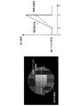
図3の左側に本実施例に係る表示装置の表示画像の一例を示し、図3の右側に、当該表示画像に示された矢印部分における表示輝度の分布を示す。図3は、階調値が0の黒背景内に黒背景よりも明るい注目オブジェクトが存在する例を示す。注目オブジェクトは黒背景よりも明るいため、注目オブジェクトを含む分割領域に対応する光源は、黒背景のみを含む分割領域よりも高い発光輝度で発光する。その結果、黒背景の領域のうち、注目オブジェクト周辺の領域では、他の領域よりも黒浮き量が大きくなってしまう。図3において、注目領域周辺の円状の領域が、黒浮き量の大きい領域(黒浮き領域)である。このような大きな黒浮きは、注目オブジェクトの視認性を悪化させる。
(effect)
An example of the display image of the display device according to the present embodiment is shown on the left side of FIG. 3, and the display luminance distribution in the arrow portion shown in the display image is shown on the right side of FIG. FIG. 3 shows an example in which an object of interest brighter than a black background exists in a black background with a gradation value of 0. Since the target object is brighter than the black background, the light source corresponding to the divided area including the target object emits light with a higher emission luminance than the divided area including only the black background. As a result, the black floating amount is larger in the area around the target object in the black background area than in other areas. In FIG. 3, a circular area around the attention area is an area with a large black floating amount (black floating area). Such large black float deteriorates the visibility of the object of interest.
ここで、注目オブジェクトの視認性を改善するために表示輝度を明るくするユーザ操作が行われると、画像データに応じてバックライトの発光輝度を制御する従来の表示装置では、当該ユーザ操作によって発光輝度も高められてしまう。その結果、図7に示すように、注目オブジェクト周辺の領域における黒浮き量が増大してしまい、視認性がさらに悪化してしまう。但し、このような従来の方法によれば、画素間の階調値(画素値)のバランスを崩すことなく表示画像のコントラストを高めることができる。そこで、本実施例では、第2のモードにおいて、このような処理が行われるようにしている。 Here, when a user operation is performed to increase the display brightness in order to improve the visibility of the object of interest, in the conventional display device that controls the light emission brightness of the backlight according to the image data, the light emission brightness is determined by the user operation. Will be raised. As a result, as shown in FIG. 7, the amount of floating black in the area around the object of interest increases, and the visibility further deteriorates. However, according to such a conventional method, the contrast of the display image can be increased without breaking the balance of the gradation values (pixel values) between the pixels. Therefore, in this embodiment, such processing is performed in the second mode.
一方、本実施例の第2のモードによれば、ユーザ指示ゲイン値が乗算される前の画像データから特徴量が取得される。そのため、ユーザ指示ゲイン値が変動しても、特徴量取得部103が取得する特徴量は変動せず、各光源の発光輝度も変動しない。その結果、黒浮き量の増加を抑制しながら表示画像の明るさを調整することができる。具体的には、図4に示すように、ユーザ指示ゲイン値を高めることにより、黒背景の表示輝度を変えることなく、注目オブジェクトの領域の表示輝度のみを高めることができ、注目オブジェクトの視認性を高めることができる。
また、本実施例では、階調値毎にユーザ指示ゲイン値の上限値を設定したため、入力画像データにおいて階調値が同じ画素の表示輝度が、階調値の飽和によってばらつくことを抑制することができる。換言すれば、入力画像データにおいて階調値が同じ画素を、同じ
輝度で表示することができる。
On the other hand, according to the second mode of the present embodiment, the feature amount is acquired from the image data before being multiplied by the user instruction gain value. Therefore, even if the user instruction gain value fluctuates, the feature amount acquired by the feature
Further, in this embodiment, since the upper limit value of the user instruction gain value is set for each gradation value, the display luminance of pixels having the same gradation value in the input image data is prevented from varying due to saturation of the gradation value. Can do. In other words, pixels having the same gradation value in the input image data can be displayed with the same luminance.
なお、本実施例では、表示装置が第1のモードと第2のモードを有する例を説明したが、これに限らない。例えば、表示装置は、第1のモードのみを有し、常に第1のモードで動作してもよい。
なお、本実施例では、輝度調整処理だけでなく、補償処理も行う例を説明したが、補償処理は行わなくてもよい。補償処理を行わない場合には、画像処理部111は、入力画像データに対し輝度調整処理を施し、輝度調整処理が施された後の画像データを液晶パネルに出力すればよい。
なお、本実施例では、輝度調整処理が施される前の画像データから特徴量を取得する例を説明したが、これに限らない。輝度調整処理が施された後の画像データに比べて輝度調整処理が施される前の画像データに近い画像データから特徴量を取得すれば、黒浮き量の増加を抑制しながら表示画像の明るさを調整することができる。但し、特徴量を取得する画像データが輝度調整処理が施される前の画像データに近いほど、黒浮き量の増加をより抑制することができる。
In this embodiment, the example in which the display device has the first mode and the second mode has been described, but the present invention is not limited to this. For example, the display device may have only the first mode and always operate in the first mode.
In this embodiment, the example in which not only the brightness adjustment process but also the compensation process is performed has been described. However, the compensation process may not be performed. When the compensation process is not performed, the
In the present embodiment, the example in which the feature amount is acquired from the image data before the luminance adjustment process is performed has been described, but the present invention is not limited to this. If the feature value is obtained from image data that is closer to the image data before the brightness adjustment process compared to the image data after the brightness adjustment process, the brightness of the displayed image is suppressed while suppressing an increase in the amount of black float Can be adjusted. However, as the image data for acquiring the feature amount is closer to the image data before the luminance adjustment process is performed, the increase in the amount of black float can be further suppressed.
なお、本実施例では、階調値毎にユーザ指示ゲイン値の上限値を設定する例を説明したが、これに限らない。例えば、ユーザ指示ゲインがユーザ指示ゲイン上限値を超える画素については、強制的に階調値を飽和させてもよい。また、ユーザ指示ゲインがユーザ指示ゲイン上限値を超える画素については、第1ゲイン乗算部107から所定の階調値を出力されてもよい。このような制御を行うことにより、入力画像データにおいて階調値が同じ画素の表示輝度が、階調値の飽和によってばらつくことを抑制することができる。また、ユーザ指示ゲイン値が上限値に達していることを明示することができ、ユーザの利便性を向上できる。
In this embodiment, the example in which the upper limit value of the user instruction gain value is set for each gradation value has been described. However, the present invention is not limited to this. For example, for a pixel whose user instruction gain exceeds the user instruction gain upper limit value, the gradation value may be forcibly saturated. Further, for a pixel whose user instruction gain exceeds the user instruction gain upper limit value, a predetermined gradation value may be output from the
なお、本実施例では、暫定補償ゲイン値を算出してユーザ指示ゲイン上限値を算出する例を説明した。つまり、階調値毎に、その階調値に応じた発光輝度で光源が発光する場合を想定してユーザ指示ゲイン上限値を算出する例を説明した。しかし、ユーザ指示ゲイン上限値の算出方法はこれに限らない。例えば、実際に決定された目標輝度を用いて、ユーザ指示ゲイン上限値が算出されてもよい。具体的には、目標輝度決定部104によって決定された分割領域毎の目標輝度の最小値(最小目標輝度)を用いてユーザ指示ゲイン上限値が決定されてもよい。このような制御を行うことにより、最小目標輝度が小さいほどユーザ指示ゲイン上限値を大きくすることができ、できる限り大きい明るさ調整幅を確保することができる。
In this embodiment, the example in which the provisional compensation gain value is calculated to calculate the user instruction gain upper limit value has been described. That is, the example in which the user instruction gain upper limit value is calculated assuming that the light source emits light with the light emission luminance corresponding to the gradation value for each gradation value has been described. However, the calculation method of the user instruction gain upper limit value is not limited to this. For example, the user instruction gain upper limit value may be calculated using the actually determined target luminance. Specifically, the user-designated gain upper limit value may be determined using the minimum target luminance value (minimum target luminance) for each divided area determined by the target
<実施例2>
以下、本発明の実施例2に係る表示装置及びその制御方法について説明する。
本実施例に係る表示装置の全体構成は実施例1と同様であるため、その説明は省略し、以下では、実施例1と異なる動作をする機能部についてのみ説明する。
<Example 2>
Hereinafter, a display device and a control method thereof according to Embodiment 2 of the present invention will be described.
Since the overall configuration of the display device according to the present embodiment is the same as that of the first embodiment, description thereof is omitted, and only functional units that operate differently from the first embodiment will be described below.
本実施例では、モード切り替え部101は、ユーザから指示されたゲイン制限値K(閾値)を設定し、ユーザから指示されたユーザ指示ゲイン値を設定する。
そして、設定されているユーザ指示ゲイン値がゲイン制限値K以下(閾値以下)である場合に、モード切り替え部101は、第2ゲイン乗算部102にユーザ指示ゲイン値を出力し、ゲイン混合部106にゲイン値1を出力する。その結果、ユーザ指示ゲイン値で輝度が調整された後の画像データから特徴量が取得されることとなる。
一方、設定されているユーザ指示ゲイン値がゲイン制限値Kより大きい場合には、モード切り替え部101は、第2ゲイン乗算部102にゲイン制限値Kを出力し、ゲイン混合部106にユーザ指示ゲイン値をゲイン制限値Kで除算した値を出力する。その結果、ゲイン制限値Kと等しいゲイン値(上昇率)で輝度が調整された後の画像データから特徴量
が取得されることとなる。
In this embodiment, the
When the set user instruction gain value is equal to or less than the gain limit value K (threshold value or less), the
On the other hand, when the set user instruction gain value is larger than the gain limit value K, the
以上の処理を行えば、ゲイン制限値Kが1に近いほど入力画像データに近い画像データから特徴量が取得されることになるため、ゲイン制限値Kが1に近いほど黒レベルを変動しにくくすることができる。しかし、ゲイン制限値Kが1に近いほど画像データが飽和しやすくなる。そして、ゲイン制限値Kとして1を設定した場合には、実施例1における第1のモードと同じ動作を行うことができ、黒レベルの変動量を0にすることができる。
また、ゲイン制限値Kが大きいほど輝度調整処理が施された後の画像データに近い画像データが取得されることになるため、ゲイン制限値Kが大きいほど黒レベルが変動しやすくなる。しかし、ゲイン制限値Kが大きいほど画像データを飽和しにくくすることができる。そして、ゲイン制限値Kとしてユーザ指示ゲイン値以上の値を設定した場合には、実施例1における第2のモードと同じ動作を行うことができる。
また、本実施例では、ゲイン制限値Kをユーザが調整可能であるため、黒レベルの安定性と画像データの飽和度合いとのバランスを任意に調整でき、ユーザの利便性を向上できる。
なお、本実施例では、ゲイン制限値K(閾値)がユーザによって設定される例を説明したが、ゲイン制限値Kは予め定められた固定値であってもよい。
If the above processing is performed, the feature amount is acquired from the image data closer to the input image data as the gain limit value K is closer to 1, so that the black level is less likely to change as the gain limit value K is closer to 1. can do. However, the closer the gain limit value K is to 1, the more easily the image data is saturated. When 1 is set as the gain limit value K, the same operation as in the first mode in the first embodiment can be performed, and the black level variation amount can be set to zero.
In addition, as the gain limit value K is larger, image data closer to the image data after the luminance adjustment processing is performed is acquired. Therefore, as the gain limit value K is larger, the black level is more likely to fluctuate. However, the larger the gain limit value K, the more difficult it is to saturate the image data. When the gain limit value K is set to a value equal to or greater than the user-designated gain value, the same operation as in the second mode in the first embodiment can be performed.
In this embodiment, since the user can adjust the gain limit value K, the balance between the stability of the black level and the degree of saturation of the image data can be arbitrarily adjusted, and the convenience for the user can be improved.
In this embodiment, the example in which the gain limit value K (threshold value) is set by the user has been described. However, the gain limit value K may be a fixed value set in advance.
<実施例3>
以下、本発明の実施例3に係る表示装置及びその制御方法について説明する。
(全体構成)
図5は、本実施例に係る液晶表示装置の機能構成の一例を示すブロック図である。
なお、実施例1と同じ機能部には実施例1と同じ符号を付し、その説明は省略する。
以下に、実施例1と異なる機能部について説明する。
<Example 3>
Hereinafter, a display device and a control method thereof according to Embodiment 3 of the present invention will be described.
(overall structure)
FIG. 5 is a block diagram illustrating an example of a functional configuration of the liquid crystal display device according to the present embodiment.
In addition, the same code | symbol as Example 1 is attached | subjected to the same function part as Example 1, and the description is abbreviate | omitted.
The functional units different from those in the first embodiment will be described below.
暗画像判断部212は、入力画像データ(輝度調整処理が施される前の画像データ)が暗い画像のデータ(暗画像データ)であるか否かを判断し、判断結果(暗画像判断結果)をモード切り替え部201に出力する。例えば、暗画像判断部212は、入力画像データの平均階調値(平均画素値)を算出し、平均階調値を所定の閾値と比較する。そして、暗画像判断部212は、平均階調値が所定の閾値以下である場合に、入力画像データが暗画像データであると判断する。
なお、入力画像データが暗画像データであるか否かの判断方法は上記方法に限らない。例えば、入力画像データの画素のうち、階調値が所定の階調値以下である画素の数が所定数以上である場合に、入力画像データが暗画像データであると判断してもよい。
The dark
The method for determining whether or not the input image data is dark image data is not limited to the above method. For example, the input image data may be determined to be dark image data when the number of pixels having a gradation value equal to or smaller than a predetermined gradation value among the pixels of the input image data is equal to or greater than a predetermined number.
画像処理部211は、画像処理部111のモード切り替え部101をモード切り替え部201に置き換えた構成を有する。
モード切り替え部201は、ユーザから指示されたユーザ指示ゲイン値を取得するとともに、暗画像判断結果を取得する。そして、入力画像データが暗画像データであると判断された場合には、ユーザ指示ゲイン値をゲイン混合部106に出力し、ゲイン値1を第2ゲイン乗算部102に出力する。入力画像データが暗画像データでないと判断された場合には、ユーザ指示ゲイン値を第2ゲイン乗算部102に出力し、ゲイン値1をゲイン混合部106に出力する。
その結果、入力画像データが暗画像データであると判断された場合には、入力画像データ(輝度調整処理が施される前の画像データ)から特徴量が取得されることなる。そして、入力画像データが暗画像データでないと判断された場合には、輝度調整処理が施された後の画像データから特徴量が取得されることなる。
The
The
As a result, when it is determined that the input image data is dark image data, the feature amount is acquired from the input image data (image data before the luminance adjustment process is performed). When it is determined that the input image data is not dark image data, the feature amount is acquired from the image data after the luminance adjustment processing is performed.
入力画像データの輝度が低いほど、入力画像データの輝度に対して黒浮き量が相対的に大きくなるため、黒浮きによる表示画像の視認性の劣化の度合いも大きくなり、黒浮きに
よる画質上の妨害感が増す。一方、入力画像データの輝度が高いほど、入力画像データの輝度に対して黒浮き量が相対的に小さくなるため、黒浮きによる表示画像の視認性の劣化の度合いも小さくなり、黒浮きによる画質上の妨害感は低減する。
上述したように、本実施例では、入力画像データが暗画像データであると判断された場合には、入力画像データ(輝度調整処理が施される前の画像データ)から特徴量が取得される。それにより、黒浮きによる表示画像の視認性の劣化の度合いが大きい場合に、黒浮き量の増加を抑制しながら表示画像の明るさを調整することができる。
そして、本実施例では、入力画像データが暗画像データでないと判断された場合には、輝度調整処理が施された後の画像データから特徴量が取得される。それにより、黒浮きによる表示画像の視認性の劣化の度合いが小さい場合に、画素間の階調値のバランスを崩すことなく表示画像のコントラストを高めることができる。
The lower the brightness of the input image data, the greater the amount of black float relative to the brightness of the input image data. Therefore, the degree of deterioration in the visibility of the display image due to black float increases and the image quality due to black float increases. Increases the sense of obstruction. On the other hand, the higher the brightness of the input image data, the smaller the amount of black float relative to the brightness of the input image data. The above disturbance is reduced.
As described above, in this embodiment, when it is determined that the input image data is dark image data, the feature amount is acquired from the input image data (image data before the luminance adjustment process). . Thereby, when the degree of deterioration of the visibility of the display image due to black floating is large, it is possible to adjust the brightness of the display image while suppressing an increase in the amount of black floating.
In this embodiment, when it is determined that the input image data is not dark image data, the feature amount is acquired from the image data after the brightness adjustment processing is performed. As a result, when the degree of deterioration in the visibility of the display image due to floating in the black is small, it is possible to increase the contrast of the display image without losing the balance of gradation values between pixels.
なお、本実施例では、入力画像データが暗画像データであるか否かを判定する閾値が予め定められている場合の例を説明したが、そのような閾値はユーザが調整可能な値であってもよい。それにより、ユーザが黒レベルの安定度を調整可能となる。例えば、画像データの取り得る値の最大値を上記閾値として設定すれば、入力画像データが常に暗部画像データであると判断されるため、表示装置を常に実施例1に記載の第1のモードで動作させることができる。 In the present embodiment, an example in which a threshold value for determining whether or not the input image data is dark image data has been set in advance. However, such a threshold value is a value that can be adjusted by the user. May be. Thereby, the user can adjust the stability of the black level. For example, if the maximum value that can be taken by the image data is set as the threshold value, it is determined that the input image data is always dark part image data. Therefore, the display device is always in the first mode described in the first embodiment. It can be operated.
また、本実施例の思想を実施例2と組み合わせてもよい。例えば、入力画像データの輝度を判断し、判断された輝度が低いほどゲイン制限値Kが大きくなるように、判断された輝度に応じてゲイン制限値Kを変更してもよい。変更後のゲイン制限値Kは、例えば、入力画像データの輝度とゲイン制限値Kとの対応関係を表す関数やテーブルを用いて決定される。それにより、実施例2におけるゲイン制限値Kを入力画像データの輝度に応じて自動的に設定することができる。 Further, the idea of the present embodiment may be combined with the second embodiment. For example, the brightness of the input image data may be determined, and the gain limit value K may be changed according to the determined brightness so that the gain limit value K increases as the determined brightness decreases. The changed gain limit value K is determined using, for example, a function or table that represents the correspondence between the luminance of the input image data and the gain limit value K. Thereby, the gain limit value K in the second embodiment can be automatically set according to the luminance of the input image data.
<実施例4>
以下、本発明の実施例4に係る表示装置及びその制御方法について説明する。
本実施例では、表示装置が、画像データにグラフィック画像データを合成し、グラフィック画像が重畳された画像を表示することのできる表示装置である。グラフィック画像データは、表示装置内部または外部にて生成されたOSD画像等のグラフィック画像のデータである。
<Example 4>
Hereinafter, a display device and a control method thereof according to Embodiment 4 of the present invention will be described.
In the present embodiment, the display device is a display device that can synthesize graphic image data with image data and display an image on which the graphic image is superimposed. The graphic image data is graphic image data such as an OSD image generated inside or outside the display device.
(全体構成)
図6は、本実施例に係る液晶表示装置の機能構成の一例を示すブロック図である。
なお、実施例1と同じ機能部には実施例1と同じ符号を付し、その説明は省略する。
以下に、実施例1と異なる機能部について説明する。
(overall structure)
FIG. 6 is a block diagram illustrating an example of a functional configuration of the liquid crystal display device according to the present embodiment.
In addition, the same code | symbol as Example 1 is attached | subjected to the same function part as Example 1, and the description is abbreviate | omitted.
The functional units different from those in the first embodiment will be described below.
画像処理部311は、画像処理部111のゲイン混合部106をゲイン混合部306に置き換えた構成を有する。また、画像処理部311は、グラフィック重畳部312との間でデータのやりとりを行う。
The
グラフィック画像は、入力画像データとは無関係であり、ユーザが表示装置を操作するために用いられることがある。そのため、グラフィック画像は、入力画像データに基づく画像とは独立して安定した輝度で表示されることが好ましい。 The graphic image is not related to the input image data and may be used by the user to operate the display device. Therefore, it is preferable that the graphic image is displayed with a stable brightness independently of the image based on the input image data.
このような表示を行うための方法の1つとして、入力画像データに輝度調整処理を施してから、輝度調整処理が施された後の画像データにグラフィック画像データを合成する方法が考えられる。このような方法を用いれば、グラフィック画像データが合成された後の画像データ(合成画像データ)から取得した特徴量に基づいて各光源の発光輝度を制御し
て合成画像データを表示することで、グラフィック画像を安定して表示することができる。しかしながら、この場合には、ユーザ指示ゲイン値が乗算された後の画像データから特徴量が取得されるため、ユーザ指示ゲイン値の変動によって特徴量が変動してしまう。すなわち、ユーザ指示ゲイン値の変動によって光源の発光輝度が変動してしまう。
As one of the methods for performing such display, a method is conceivable in which the luminance adjustment process is performed on the input image data and then the graphic image data is synthesized with the image data after the luminance adjustment process. By using such a method, by controlling the emission luminance of each light source based on the feature amount acquired from the image data (synthesized image data) after the graphic image data is synthesized, the synthesized image data is displayed. Graphic images can be displayed stably. However, in this case, since the feature amount is acquired from the image data after being multiplied by the user instruction gain value, the feature amount changes due to the change of the user instruction gain value. That is, the light emission luminance of the light source varies due to the variation of the user instruction gain value.
そこで、本実施例では、グラフィックス画像が重畳された画像を表示する場合に、画像処理部311に以下の処理を行わせる。すなわち、グラフィック画像の輝度が変化しないように輝度調整処理を行わせる。具体的には、グラフィックス画像の画素にユーザ調整ゲイン値が乗算されないように輝度調整処理を行わせる。そして、グラフィックス画像が重畳された画像を表す画像データ(合成画像データ)から特徴量を取得させ、取得した特徴量に基づいて各光源の発光輝度を制御させる。
Therefore, in this embodiment, when displaying an image on which a graphics image is superimposed, the
グラフィック重畳部312は、第2ゲイン乗算部102から出力された画像データ(ゲイン値Gfが乗算された後の画像データ)にグラフィック画像データを合成することにより、合成画像データを生成する。そして、グラフィック重畳部312は、合成画像データを特徴量取得部103、ゲイン混合部306、及び、第1ゲイン乗算部107に出力する。また、グラフィック重畳部312は、グラフィック画像の領域を表す領域情報をゲイン混合部306に出力する。領域情報は、例えば、グラフィック画像の領域の始点座標と終点座標である。始点座標は、例えば、領域の左上隅の座標である。終点座標は、例えば、領域の右下隅の座標である。
なお、領域情報は、上記情報に限らない。グラフィック画像の領域を表す情報であれば、領域情報はどのような情報であってもよい。例えば、領域情報は、グラフィック画像の領域の位置とサイズであってもよい。
The
The area information is not limited to the above information. As long as the information represents the area of the graphic image, the area information may be any information. For example, the area information may be the position and size of the area of the graphic image.
ゲイン混合部306は、モード切り替え部101よりユーザ指示ゲイン値を取得した場合、すなわち第1のモードが設定されている場合に、以下の処理を行う。即ち、ゲイン混合部306は、グラフィック画像の画素以外の画素については、実施例1と同様に、輝度補償ゲイン値とユーザ指示ゲイン値を混合した混合ゲイン値を算出し、算出した混合ゲイン値を出力する。そして、ゲイン混合部306は、グラフィック画像の画素については、輝度補償ゲイン値を混合ゲイン値として出力する。
The
このような構成によれば、第1のモードが設定されている場合に、入力画像データにグラフィックス画像データが合成された合成画像データから特徴量が取得され、取得された特徴量に基づいて各光源の発光輝度が制御される。それにより、ユーザ指示ゲイン値の変動による発光輝度の変動を防止することができるとともに、グラフィック画像を考慮した発光輝度で光源を発光させることができる。そして、グラフィック画像の画素以外の画素については、階調値にユーザ指示ゲイン値と輝度補償ゲイン値が乗算され、グラフィック画像の画素については、階調値にユーザ指示ゲイン値が乗算されず、輝度補償ゲイン値のみが乗算される。それにより、黒浮き量の増加を抑制しながら表示画像の明るさを調整することができるとともに、グラフィック画像を安定した輝度で表示することができる。
このように、本実施例によれば、グラフィック表示輝度の安定性と、黒レベルの安定性とを両立した、輝度調整機能(画面の明るさを調整する機能)を提供することができる。
According to such a configuration, when the first mode is set, the feature amount is acquired from the combined image data obtained by combining the graphics image data with the input image data, and based on the acquired feature amount. The light emission luminance of each light source is controlled. As a result, it is possible to prevent fluctuations in the light emission luminance due to fluctuations in the user-designated gain value, and it is possible to cause the light source to emit light with a light emission luminance considering a graphic image. Then, for pixels other than the graphic image pixel, the gradation value is multiplied by the user-indicated gain value and the luminance compensation gain value, and for the graphic image pixel, the gradation value is not multiplied by the user-indicated gain value. Only the compensation gain value is multiplied. Accordingly, the brightness of the display image can be adjusted while suppressing an increase in the amount of black floating, and the graphic image can be displayed with stable luminance.
As described above, according to the present embodiment, it is possible to provide a brightness adjustment function (function for adjusting the brightness of the screen) that achieves both the stability of the graphic display brightness and the stability of the black level.
なお、本実施例では、表示装置がグラフィック画像を重畳する処理を行う例を説明したが、当該処理は外部の装置で行われてもよい。そして、入力画像データとしてグラフィック画像が重畳された画像を表す画像データが入力されてもよい。その場合には、画像データに付加されているメタデータなどを用いて、グラフィック画像が重畳されているか否かを判断したり、グラフィック画像が重畳されている領域を判断して、グラフィック画像の領域以外の領域に対して輝度調整処理を施したりすればよい。 In this embodiment, the example in which the display device performs the process of superimposing the graphic image has been described. However, the process may be performed by an external device. Then, image data representing an image on which a graphic image is superimposed may be input as input image data. In that case, using the metadata added to the image data, it is determined whether the graphic image is superimposed, the area where the graphic image is superimposed is determined, and the area of the graphic image is determined. The brightness adjustment process may be performed on the other area.
なお、本実施例では、グラフィックの表示輝度の安定性と黒レベルの安定性とを両立するため上述のような構成を採用したが、これに限らない。例えば、グラフィック画像を表示するときに強制的に第1のモードを無効にしてもよい。そして、グラフィック画像を表示するときに強制的に第1のモード以外の動作モード(例えば第2のモード)を有効にしてもよい。それにより、第1のモードが設定されているときに、グラフィック画像の画素にユーザ調整ゲインが乗算され、グラフィック画像の表示輝度が変わってしまうことを防止することができる。 In the present embodiment, the above-described configuration is adopted in order to achieve both the stability of graphic display luminance and the stability of black level. However, the present invention is not limited to this. For example, the first mode may be forcibly disabled when displaying a graphic image. Then, an operation mode other than the first mode (for example, the second mode) may be forcibly enabled when displaying a graphic image. Thereby, when the first mode is set, it is possible to prevent the display luminance of the graphic image from being changed by multiplying the pixel of the graphic image by the user adjustment gain.
<その他の実施例>
記憶装置に記録されたプログラムを読み込み実行することで前述した実施例の機能を実現するシステムや装置のコンピュータ(又はCPU、MPU等のデバイス)によっても、本発明を実施することができる。また、例えば、記憶装置に記録されたプログラムを読み込み実行することで前述した実施例の機能を実現するシステムや装置のコンピュータによって実行されるステップからなる方法によっても、本発明を実施することができる。この目的のために、上記プログラムは、例えば、ネットワークを通じて、又は、上記記憶装置となり得る様々なタイプの記録媒体(つまり、非一時的にデータを保持するコンピュータ読取可能な記録媒体)から、上記コンピュータに提供される。したがって、上記コンピュータ(CPU、MPU等のデバイスを含む)、上記方法、上記プログラム(プログラムコード、プログラムプロダクトを含む)、上記プログラムを非一時的に保持するコンピュータ読取可能な記録媒体は、いずれも本発明の範疇に含まれる。
<Other examples>
The present invention can also be implemented by a system (or a device such as a CPU or MPU) of a system or apparatus that implements the functions of the above-described embodiments by reading and executing a program recorded in a storage device. The present invention can also be implemented by a method comprising steps executed by a computer of a system or apparatus that implements the functions of the above-described embodiments by reading and executing a program recorded in a storage device, for example. . For this purpose, the program is stored in the computer from, for example, various types of recording media that can serve as the storage device (ie, computer-readable recording media that holds data non-temporarily). Provided to. Therefore, the computer (including devices such as CPU and MPU), the method, the program (including program code and program product), and the computer-readable recording medium that holds the program non-temporarily are all present. It is included in the category of the invention.
103・・・特徴量取得部 104・・・目標輝度決定部
108・・・液晶パネル 109・・・バックライト制御値決定部
110・・・バックライト 111,211,311・・・画像処理部
DESCRIPTION OF
Claims (19)
入力された画像データに基づいて前記発光手段からの光を変調することにより、画面上に画像を表示する表示手段と、
画像データに対し輝度を調整する輝度調整処理を施し、前記輝度調整処理が施された後の画像データを前記表示手段に出力する画像処理手段と、
前記複数の光源に対応する画面上の複数の領域のそれぞれについて、前記輝度調整処理が施された後の画像データに比べて前記輝度調整処理が施される前の画像データに近い画像データから、その領域における画像データの輝度を表す特徴量を取得する取得手段と、
前記取得手段で取得された特徴量に基づいて、各光源の発光輝度を制御する制御手段と、
を有することを特徴とする表示装置。 A light emitting means having a plurality of light sources capable of individually controlling the light emission brightness;
Display means for displaying an image on a screen by modulating light from the light emitting means based on input image data;
Image processing means for performing brightness adjustment processing for adjusting brightness on the image data, and outputting the image data after the brightness adjustment processing to the display means;
For each of a plurality of areas on the screen corresponding to the plurality of light sources, from image data close to the image data before being subjected to the luminance adjustment processing compared to image data after being subjected to the luminance adjustment processing, Acquisition means for acquiring a feature amount representing the luminance of the image data in the region;
Control means for controlling the light emission luminance of each light source based on the feature amount obtained by the obtaining means;
A display device comprising:
ことを特徴とする請求項1に記載の表示装置。 The display device according to claim 1, wherein the acquisition unit acquires a feature amount from image data before the luminance adjustment process is performed.
前記取得手段は、
前記第1のモードが設定されている場合に、前記輝度調整処理が施される前の画像データから特徴量を取得し、
前記第2のモードが設定されている場合に、前記輝度調整処理が施された後の画像データから特徴量を取得する
ことを特徴とする請求項1に記載の表示装置。 The display device has a first mode and a second mode,
The acquisition means includes
When the first mode is set, the feature amount is acquired from the image data before the luminance adjustment processing is performed,
2. The display device according to claim 1, wherein, when the second mode is set, a feature amount is acquired from image data after the luminance adjustment processing is performed.
前記取得手段は、
前記設定されている上昇率が閾値以下の場合に、当該上昇率で輝度が調整された画像データから特徴量を取得し、
前記設定されている上昇率が前記閾値より大きい場合に、前記閾値と等しい上昇率で輝度が調整された画像データから特徴量を取得する
ことを特徴とする請求項1に記載の表示装置。 The brightness adjustment process is a process of adjusting the brightness of the image data at a set rate of increase,
The acquisition means includes
When the set rate of increase is less than or equal to the threshold value, the feature amount is acquired from the image data whose luminance is adjusted at the rate of increase,
2. The display device according to claim 1, wherein when the set increase rate is larger than the threshold value, a feature amount is acquired from image data whose luminance is adjusted at an increase rate equal to the threshold value.
ことを特徴とする請求項4に記載の表示装置。 The display device according to claim 4, wherein the threshold value is a value set by a user.
前記取得手段は、前記判断手段で判断された輝度が低いほど前記閾値が大きくなるように、前記判断手段で判断された輝度に応じて前記閾値を変更する
ことを特徴とする請求項4に記載の表示装置。 A judgment means for judging the brightness of the image data before the brightness adjustment processing is performed;
The said acquisition means changes the said threshold value according to the brightness | luminance judged by the said judgment means so that the said threshold value may become large, so that the brightness | luminance judged by the said judgment means is low. Display device.
前記取得手段は、
前記輝度調整処理が施される前の画像データが暗い画像のデータであると判断された場合に、前記輝度調整処理が施される前の画像データから特徴量を取得し、
前記輝度調整処理が施される前の画像データが暗い画像のデータでないと判断された場合に、前記輝度調整処理が施された後の画像データから特徴量を取得する
ことを特徴とする請求項1に記載の表示装置。 A determination means for determining whether or not the image data before the brightness adjustment processing is dark image data;
The acquisition means includes
When it is determined that the image data before the luminance adjustment processing is dark image data, a feature amount is acquired from the image data before the luminance adjustment processing is performed,
The feature amount is obtained from the image data after the luminance adjustment processing when it is determined that the image data before the luminance adjustment processing is not dark image data. The display device according to 1.
前記画像処理手段は、グラフィック画像の輝度が変化しないように前記輝度調整処理を行い、
前記取得手段は、グラフィック画像が重畳された画像を表す画像データから特徴量を取得する
ことを特徴とする請求項1〜7のいずれか1項に記載の表示装置。 When displaying an image with a graphic image superimposed,
The image processing means performs the luminance adjustment processing so that the luminance of the graphic image does not change,
The display device according to claim 1, wherein the acquisition unit acquires a feature amount from image data representing an image on which a graphic image is superimposed.
ことを特徴とする請求項1〜8のいずれか1項に記載の表示装置。 The image processing means performs the brightness adjustment process and a compensation process for compensating for a change in brightness on the screen due to a change in light emission brightness of the light source, and performs the brightness adjustment process and the compensation process. The image data after being output is output to the display means.
The display device according to claim 1, wherein the display device is a display device.
入力された画像データに基づいて前記発光手段からの光を変調することにより、画面上に画像を表示する表示手段と、
を有する表示装置の制御方法であって、
画像データに対し輝度を調整する輝度調整処理を施し、前記輝度調整処理が施された後の画像データを前記表示手段に出力する画像処理ステップと、
前記複数の光源に対応する画面上の複数の領域のそれぞれについて、前記輝度調整処理が施された後の画像データに比べて前記輝度調整処理が施される前の画像データに近い画像データから、その領域における画像データの輝度を表す特徴量を取得する取得ステップと、
前記取得ステップで取得された特徴量に基づいて、各光源の発光輝度を制御する制御ステップと、
を有することを特徴とする表示装置の制御方法。 A light emitting means having a plurality of light sources capable of individually controlling the light emission brightness;
Display means for displaying an image on a screen by modulating light from the light emitting means based on input image data;
A display device control method comprising:
An image processing step of performing luminance adjustment processing for adjusting luminance on the image data, and outputting the image data after the luminance adjustment processing to the display unit;
For each of a plurality of areas on the screen corresponding to the plurality of light sources, from image data close to the image data before being subjected to the luminance adjustment processing compared to image data after being subjected to the luminance adjustment processing, An obtaining step for obtaining a feature amount representing luminance of image data in the region;
A control step of controlling the light emission luminance of each light source based on the feature amount acquired in the acquisition step;
A control method for a display device, comprising:
ことを特徴とする請求項10に記載の表示装置の制御方法。 The method for controlling a display device according to claim 10, wherein in the obtaining step, a feature amount is obtained from image data before the luminance adjustment processing is performed.
前記取得ステップでは、
前記第1のモードが設定されている場合に、前記輝度調整処理が施される前の画像データから特徴量を取得し、
前記第2のモードが設定されている場合に、前記輝度調整処理が施された後の画像データから特徴量を取得する
ことを特徴とする請求項10に記載の表示装置の制御方法。 The display device has a first mode and a second mode,
In the acquisition step,
When the first mode is set, the feature amount is acquired from the image data before the luminance adjustment processing is performed,
The method for controlling a display device according to claim 10, wherein, when the second mode is set, a feature amount is acquired from image data after the luminance adjustment processing is performed.
前記取得ステップでは、
前記設定されている上昇率が閾値以下の場合に、当該上昇率で輝度が調整された画像データから特徴量を取得し、
前記設定されている上昇率が前記閾値より大きい場合に、前記閾値と等しい上昇率で輝度が調整された画像データから特徴量を取得する
ことを特徴とする請求項10に記載の表示装置の制御方法。 The brightness adjustment process is a process of adjusting the brightness of the image data at a set rate of increase,
In the acquisition step,
When the set rate of increase is less than or equal to the threshold value, the feature amount is acquired from the image data whose luminance is adjusted at the rate of increase,
The control of the display device according to claim 10, wherein, when the set rate of increase is larger than the threshold value, the feature amount is acquired from image data whose luminance is adjusted at a rate of increase equal to the threshold value. Method.
ことを特徴とする請求項13に記載の表示装置の制御方法。 14. The display device control method according to claim 13, wherein the threshold value is a value set by a user.
前記取得ステップでは、前記判断ステップで判断された輝度が低いほど前記閾値が大きくなるように、前記判断ステップで判断された輝度に応じて前記閾値を変更する
ことを特徴とする請求項13に記載の表示装置の制御方法。 A determination step of determining the luminance of the image data before the luminance adjustment processing is performed;
14. The acquisition step according to claim 13, wherein the threshold value is changed according to the luminance determined in the determination step so that the threshold value increases as the luminance determined in the determination step decreases. Display device control method.
前記取得ステップでは、
前記輝度調整処理が施される前の画像データが暗い画像のデータであると判断された場合に、前記輝度調整処理が施される前の画像データから特徴量を取得し、
前記輝度調整処理が施される前の画像データが暗い画像のデータでないと判断された場合に、前記輝度調整処理が施された後の画像データから特徴量を取得する
ことを特徴とする請求項10に記載の表示装置の制御方法。 A determination step of determining whether or not the image data before the brightness adjustment processing is dark image data;
In the acquisition step,
When it is determined that the image data before the luminance adjustment processing is dark image data, a feature amount is acquired from the image data before the luminance adjustment processing is performed,
The feature amount is obtained from the image data after the luminance adjustment processing when it is determined that the image data before the luminance adjustment processing is not dark image data. 11. A method for controlling a display device according to 10.
前記画像処理ステップでは、グラフィック画像の輝度が変化しないように前記輝度調整処理を行い、
前記取得ステップでは、グラフィック画像が重畳された画像を表す画像データから特徴量を取得する
ことを特徴とする請求項10〜16のいずれか1項に記載の表示装置の制御方法。 When displaying an image with a graphic image superimposed,
In the image processing step, the luminance adjustment processing is performed so that the luminance of the graphic image does not change,
17. The display device control method according to claim 10, wherein in the obtaining step, a feature amount is obtained from image data representing an image on which a graphic image is superimposed.
ことを特徴とする請求項10〜17のいずれか1項に記載の表示装置の制御方法。 In the image processing step, the brightness adjustment process and a compensation process for compensating for a change in brightness on the screen due to a change in emission brightness of the light source are performed on the image data, and the brightness adjustment process and the compensation process are performed. The image data after being output is output to the display means.
The method for controlling a display device according to any one of claims 10 to 17,
Priority Applications (1)
| Application Number | Priority Date | Filing Date | Title |
|---|---|---|---|
| JP2013149751A JP2015022123A (en) | 2013-07-18 | 2013-07-18 | Display device, control method of display device, and program |
Applications Claiming Priority (1)
| Application Number | Priority Date | Filing Date | Title |
|---|---|---|---|
| JP2013149751A JP2015022123A (en) | 2013-07-18 | 2013-07-18 | Display device, control method of display device, and program |
Publications (2)
| Publication Number | Publication Date |
|---|---|
| JP2015022123A true JP2015022123A (en) | 2015-02-02 |
| JP2015022123A5 JP2015022123A5 (en) | 2016-09-01 |
Family
ID=52486634
Family Applications (1)
| Application Number | Title | Priority Date | Filing Date |
|---|---|---|---|
| JP2013149751A Pending JP2015022123A (en) | 2013-07-18 | 2013-07-18 | Display device, control method of display device, and program |
Country Status (1)
| Country | Link |
|---|---|
| JP (1) | JP2015022123A (en) |
Cited By (2)
| Publication number | Priority date | Publication date | Assignee | Title |
|---|---|---|---|---|
| JP2016167011A (en) * | 2015-03-10 | 2016-09-15 | キヤノン株式会社 | Image display device and control method thereof |
| JP2019049706A (en) * | 2017-09-08 | 2019-03-28 | アップル インコーポレイテッドApple Inc. | Burn-in statistics and burn-in compensation |
Citations (2)
| Publication number | Priority date | Publication date | Assignee | Title |
|---|---|---|---|---|
| JP2008203292A (en) * | 2007-02-16 | 2008-09-04 | Seiko Epson Corp | Image display device and image display method |
| JP2011048040A (en) * | 2009-08-26 | 2011-03-10 | Sony Corp | Video signal processing apparatus, method of processing video signal, and program |
-
2013
- 2013-07-18 JP JP2013149751A patent/JP2015022123A/en active Pending
Patent Citations (2)
| Publication number | Priority date | Publication date | Assignee | Title |
|---|---|---|---|---|
| JP2008203292A (en) * | 2007-02-16 | 2008-09-04 | Seiko Epson Corp | Image display device and image display method |
| JP2011048040A (en) * | 2009-08-26 | 2011-03-10 | Sony Corp | Video signal processing apparatus, method of processing video signal, and program |
Cited By (4)
| Publication number | Priority date | Publication date | Assignee | Title |
|---|---|---|---|---|
| JP2016167011A (en) * | 2015-03-10 | 2016-09-15 | キヤノン株式会社 | Image display device and control method thereof |
| JP2019049706A (en) * | 2017-09-08 | 2019-03-28 | アップル インコーポレイテッドApple Inc. | Burn-in statistics and burn-in compensation |
| US11361729B2 (en) | 2017-09-08 | 2022-06-14 | Apple Inc. | Burn-in statistics and burn-in compensation |
| US11823642B2 (en) | 2017-09-08 | 2023-11-21 | Apple Inc. | Burn-in statistics and burn-in compensation |
Similar Documents
| Publication | Publication Date | Title |
|---|---|---|
| JP5805109B2 (en) | Method for enhancing an image for display on a liquid crystal display, graphic processing apparatus, and computer-readable medium | |
| JP5911518B2 (en) | Display device, display device control method, and program | |
| JP6071469B2 (en) | Image display apparatus and control method thereof | |
| JP2016038567A (en) | Display device and control method of the same | |
| JP2012242672A (en) | Liquid crystal display and control method thereof | |
| JP6242092B2 (en) | Display device, display device control method, and program | |
| JP2015018219A (en) | Image display device and method for controlling the same | |
| US20190289217A1 (en) | Display apparatus, control method thereof, and non-transitory computer readable medium | |
| JP2017045030A (en) | Image display device | |
| JPWO2017098676A1 (en) | Display device and backlight control method | |
| WO2017037997A1 (en) | Display apparatus, method for controlling the same, program, and storage medium | |
| JP2015022123A (en) | Display device, control method of display device, and program | |
| JP2016212195A (en) | Image display device, image display system, and method for controlling them | |
| US9396700B2 (en) | Display apparatus and control method thereof | |
| JP2015232689A (en) | Image display device and method for controlling the same | |
| JP6818781B2 (en) | Display device and its control method | |
| US20190139500A1 (en) | Display apparatus and control method thereof | |
| JP6180135B2 (en) | Image display apparatus and control method thereof | |
| JP2015212783A (en) | Image display device, method for controlling image display device, and program | |
| JP2015088998A (en) | Display device, method of controlling the same, and program | |
| JP2015222297A (en) | Image display device and control method thereof | |
| JP6494195B2 (en) | Image display apparatus, image display apparatus control method, and program | |
| JP2015081996A (en) | Display device, control method and program of display device | |
| WO2019239928A1 (en) | Control device, display device, and control method | |
| JP2015004843A (en) | Display device, control method for display device, and program |
Legal Events
| Date | Code | Title | Description |
|---|---|---|---|
| A521 | Written amendment |
Free format text: JAPANESE INTERMEDIATE CODE: A523 Effective date: 20160714 |
|
| A621 | Written request for application examination |
Free format text: JAPANESE INTERMEDIATE CODE: A621 Effective date: 20160714 |
|
| A977 | Report on retrieval |
Free format text: JAPANESE INTERMEDIATE CODE: A971007 Effective date: 20170413 |
|
| A131 | Notification of reasons for refusal |
Free format text: JAPANESE INTERMEDIATE CODE: A131 Effective date: 20170425 |
|
| A02 | Decision of refusal |
Free format text: JAPANESE INTERMEDIATE CODE: A02 Effective date: 20171031 |