JP6494195B2 - Image display apparatus, image display apparatus control method, and program - Google Patents
Image display apparatus, image display apparatus control method, and program Download PDFInfo
- Publication number
- JP6494195B2 JP6494195B2 JP2014141111A JP2014141111A JP6494195B2 JP 6494195 B2 JP6494195 B2 JP 6494195B2 JP 2014141111 A JP2014141111 A JP 2014141111A JP 2014141111 A JP2014141111 A JP 2014141111A JP 6494195 B2 JP6494195 B2 JP 6494195B2
- Authority
- JP
- Japan
- Prior art keywords
- image
- light source
- feature amount
- light emission
- luminance
- Prior art date
- Legal status (The legal status is an assumption and is not a legal conclusion. Google has not performed a legal analysis and makes no representation as to the accuracy of the status listed.)
- Expired - Fee Related
Links
- 238000000034 method Methods 0.000 title claims description 84
- 230000008859 change Effects 0.000 claims description 157
- 238000001514 detection method Methods 0.000 claims description 15
- 235000019557 luminance Nutrition 0.000 description 378
- 239000002131 composite material Substances 0.000 description 59
- 238000012545 processing Methods 0.000 description 21
- 230000008569 process Effects 0.000 description 19
- 230000007423 decrease Effects 0.000 description 14
- 238000010586 diagram Methods 0.000 description 14
- 230000006870 function Effects 0.000 description 11
- 239000004973 liquid crystal related substance Substances 0.000 description 11
- 230000002123 temporal effect Effects 0.000 description 11
- 230000000694 effects Effects 0.000 description 10
- 238000009434 installation Methods 0.000 description 8
- 230000015572 biosynthetic process Effects 0.000 description 6
- 238000003702 image correction Methods 0.000 description 6
- 230000001629 suppression Effects 0.000 description 6
- 238000003786 synthesis reaction Methods 0.000 description 6
- 230000015556 catabolic process Effects 0.000 description 5
- 238000006731 degradation reaction Methods 0.000 description 5
- 238000007667 floating Methods 0.000 description 5
- 238000007796 conventional method Methods 0.000 description 4
- 230000006866 deterioration Effects 0.000 description 4
- 230000002194 synthesizing effect Effects 0.000 description 4
- 230000007704 transition Effects 0.000 description 3
- 238000006243 chemical reaction Methods 0.000 description 2
- 239000003086 colorant Substances 0.000 description 2
- 238000012937 correction Methods 0.000 description 2
- 239000000203 mixture Substances 0.000 description 2
- 230000001131 transforming effect Effects 0.000 description 2
- 238000002834 transmittance Methods 0.000 description 2
- 230000008901 benefit Effects 0.000 description 1
- 238000004891 communication Methods 0.000 description 1
- 238000005516 engineering process Methods 0.000 description 1
- 239000000284 extract Substances 0.000 description 1
- 230000007257 malfunction Effects 0.000 description 1
- 230000004048 modification Effects 0.000 description 1
- 238000012986 modification Methods 0.000 description 1
- 230000008447 perception Effects 0.000 description 1
- 230000009467 reduction Effects 0.000 description 1
- 238000011946 reduction process Methods 0.000 description 1
- 230000004044 response Effects 0.000 description 1
- 238000010187 selection method Methods 0.000 description 1
- 230000035945 sensitivity Effects 0.000 description 1
- 239000013589 supplement Substances 0.000 description 1
- 230000009466 transformation Effects 0.000 description 1
Images


Description
本発明は、画像表示装置、画像表示装置の制御方法、及び、プログラムに関する。 The present invention relates to an image display device, an image display device control method, and a program.
液晶表示装置などの画像表示装置に関する従来技術は、例えば、特許文献1〜3に開示されている。
特許文献1,3には、複数の光源を有するバックライトが開示されている。特許文献1,3に開示の技術では、複数の光源は、画面の領域を構成する複数の分割領域にそれぞれ配置されている。
特許文献1に開示の技術では、入力画像の特徴量に基づいて複数の光源の発光輝度が個別に制御される。このような制御は、“ローカルディミング制御”と呼ばれる。ローカルディミング制御を行うことにより、表示画像(画面に表示された画像)のダイナミックレンジを拡大したり、表示画像のコントラストを向上したりすることができる。ローカルディミング制御を行うことにより、画面方向における輝度値の変化(輝度傾斜)が大きい画像を表示する場合にも、上記効果を得ることができる。
特許文献2には、複数の画像を並べて表示する多画像表示時に、入力画像の特徴量に基づいてバックライトの発光輝度を制御する処理を停止する技術が開示されている。
特許文献3に開示の技術では、互いに隣接する2つの分割領域間における光源の発光輝度の差が許容値以下に制限される。それにより、互いに隣接する2つの分割領域間の境界線が視認しされる不具合を軽減することができる。
Conventional techniques relating to an image display device such as a liquid crystal display device are disclosed in
In the technique disclosed in
Patent Document 2 discloses a technique for stopping processing for controlling the light emission luminance of a backlight based on a feature amount of an input image during multi-image display in which a plurality of images are displayed side by side.
In the technique disclosed in Patent Document 3, the difference in light emission luminance of the light source between two adjacent divided areas is limited to an allowable value or less. Thereby, the malfunction that the boundary line between two division areas adjacent to each other is visually recognized can be reduced.
しかしながら、特許文献1,2の技術を組み合わせてしまうと、多画像表示時に、ローカルディミング制御が停止されてしまう。そのため、特許文献1,2の技術を組み合わせてしまうと、多画像表示時に、表示画像のダイナミックレンジを拡大する効果、及び、表示画像のコントラストを向上する効果を得ることができない。換言すれば、特許文献1,2の技術を組み合わせてしまうと、多画像表示時に、表示画像のダイナミックレンジやコントラストが低下してしまう。
However, if the techniques of
また、多画像表示時には、1つの光源からの光が複数の画像表示領域(複数の画像がそれぞれ表示される複数の領域)に照射されることがある。以後、複数の画像表示領域に光を照射する光源を“境界近傍光源”と記載する。
そして、従来のローカルディミング制御では、光源毎に、その光源の発光輝度が、当該光源が配置されている分割領域に表示される画像の特徴量に応じて制御される。境界近傍光源以外の光源が配置されている分割領域には1つの画像が表示されるため、境界近傍光源以外の光源の発光輝度は1つの画像の特徴量に応じて制御される。境界近傍光源が配置されている分割領域には1つまたは複数の画像が表示されるため、境界近傍光源の発光輝度は1つまたは複数の画像の特徴量に応じて制御される。
In addition, during multi-image display, light from one light source may be applied to a plurality of image display areas (a plurality of areas where a plurality of images are respectively displayed). Hereinafter, a light source that irradiates a plurality of image display areas with light is referred to as a “near boundary light source”.
In the conventional local dimming control, the light emission luminance of each light source is controlled according to the feature amount of the image displayed in the divided area where the light source is arranged. Since one image is displayed in the divided area where the light sources other than the light sources near the boundary are arranged, the light emission luminance of the light sources other than the light sources near the boundary is controlled according to the feature amount of the one image. Since one or more images are displayed in the divided area where the light source near the boundary is arranged, the emission luminance of the light source near the boundary is controlled according to the feature amount of the one or more images.
そのため、多画像表示時に上述した従来のローカルディミング制御を行ってしまうと、表示画像の画質劣化が生じてしまうことがある。具体的には、画像I1(例えば、静止画像)の画像表示領域を含む複数の画像表示領域に光を照射する境界近傍光源LSの発光輝度が、画像I1とは無関係な画像I2(例えば、動画像)の特徴量の変動に応じて変動することがある。そして、このような発光輝度の変動が生じると、画像I1の端部(境界近傍光源LSからの光が照射される領域)に、表示輝度(画面上の輝度)の予期せぬ変動が生じてしまう。
なお、ローカルディミング制御によって発光色が制御される場合にも、上述した画質劣化は生じ得る。
Therefore, if the above-described conventional local dimming control is performed during multi-image display, the image quality of the display image may be deteriorated. Specifically, an image I2 (for example, a moving image) in which the emission luminance of the near-boundary light source LS that irradiates light to a plurality of image display areas including the image display area of the image I1 (for example, a still image) is unrelated to the image I1. May vary according to the variation of the feature quantity of the image. When such a variation in emission luminance occurs, an unexpected variation in display luminance (brightness on the screen) occurs at the edge of the image I1 (region irradiated with light from the light source LS near the boundary). End up.
Note that the above-described image quality degradation can also occur when the emission color is controlled by local dimming control.
本発明は、多画像表示時に従来のローカルディミング制御を行うことによって生じる表示画像の画質劣化を、表示画像のダイナミックレンジやコントラストの低下を抑制しつつ、抑制することができる技術を提供することを目的とする。 The present invention provides a technique capable of suppressing deterioration in display image quality caused by performing conventional local dimming control during multi-image display while suppressing a decrease in dynamic range and contrast of the display image. Objective.
本発明の第1の態様は、
個別に発光を制御可能な複数の光源を有する発光手段と、
表示画像に基づいて、前記発光手段から照射された光を透過して画面に画像を表示する表示手段と、
各光源が対応する前記画面の領域における前記表示画像の特徴量に基づいて、各光源の発光輝度、および発光色の少なくとも一方である発光状態を制御する制御手段と、
を備え、
前記制御手段は、前記表示画像が第1画像と第2画像が異なる領域に配置される画像である場合に、
前記複数の光源のうち前記画面において前記第1画像と前記第2画像との境界を含む領域およびその近傍の領域に対応する対象光源の発光状態の変化が、
前記複数の光源のうち前記対象光源でない非対象光源の発光状態の変化に比べて抑制されるように制御する画像表示装置において、
前記第1画像の特徴量である第1特徴量を取得する第1取得手段と、
前記第2画像の特徴量である第2特徴量を取得する第2取得手段と、
をさらに有し、
前記制御手段は、前記表示画像の変化による前記対象光源の発光状態の変化が、前記非対象光源に比べて、前記第1特徴量と前記第2特徴量の差が大きいほど大きく抑制されるように、各光源の発光状態を制御する、
ことを特徴とする画像表示装置である。
本発明の第2の態様は、
個別に発光を制御可能な複数の光源を有する発光手段と、
表示画像に基づいて、前記発光手段から照射された光を透過して画面に画像を表示する表示手段と、
各光源が対応する前記画面の領域における前記表示画像の特徴量に基づいて、各光源の発光輝度、および発光色の少なくとも一方である発光状態を制御する制御手段と、
を備え、
前記制御手段は、前記表示画像が第1画像と第2画像が異なる領域に配置される画像である場合に、
前記複数の光源のうち前記画面において前記第1画像と前記第2画像との境界を含む領域およびその近傍の領域に対応する対象光源の発光状態の変化が、
前記複数の光源のうち前記対象光源でない非対象光源の発光状態の変化に比べて抑制されるように制御する画像表示装置において、
前記第1画像が動画像である場合に、前記第1画像のシーンの切り変わりを検出する第1検出手段と、
前記第2画像が動画像である場合に、前記第2画像のシーンの切り変わりを検出する第2検出手段と、
をさらに有し、
前記制御手段は、前記第1画像と前記第2画像が動画像であり、且つ、前記第1画像のシーンと前記第2画像のシーンとが同時に切り替わった場合に、前記対象光源を前記非対象光源とみなして、各光源の発光状態を制御する、
ことを特徴とする画像表示装置である。
The first aspect of the present invention is:
A light emitting means having a plurality of light sources capable of individually controlling light emission;
Display means for transmitting light emitted from the light emitting means and displaying an image on a screen based on a display image;
Control means for controlling a light emission state that is at least one of a light emission luminance and a light emission color of each light source based on a feature amount of the display image in a region of the screen corresponding to each light source;
With
When the display image is an image arranged in a region where the first image and the second image are different from each other,
A change in the light emission state of the target light source corresponding to a region including a boundary between the first image and the second image and a region in the vicinity thereof in the screen among the plurality of light sources,
In the image display device that is controlled so as to be suppressed compared to a change in the light emission state of the non-target light source that is not the target light source among the plurality of light sources,
First acquisition means for acquiring a first feature amount that is a feature amount of the first image;
Second acquisition means for acquiring a second feature amount that is a feature amount of the second image;
Further comprising
The control means is configured such that a change in a light emission state of the target light source due to a change in the display image is significantly suppressed as a difference between the first feature amount and the second feature amount is larger than that of the non-target light source. To control the light emission state of each light source,
An image display device characterized by the above.
The second aspect of the present invention is:
A light emitting means having a plurality of light sources capable of individually controlling light emission;
Display means for transmitting light emitted from the light emitting means and displaying an image on a screen based on a display image;
Control means for controlling a light emission state that is at least one of a light emission luminance and a light emission color of each light source based on a feature amount of the display image in a region of the screen corresponding to each light source;
With
When the display image is an image arranged in a region where the first image and the second image are different from each other,
A change in the light emission state of the target light source corresponding to a region including a boundary between the first image and the second image and a region in the vicinity thereof in the screen among the plurality of light sources,
In the image display device that is controlled so as to be suppressed compared to a change in the light emission state of the non-target light source that is not the target light source among the plurality of light sources,
First detection means for detecting a scene change of the first image when the first image is a moving image;
Second detection means for detecting a scene change in the second image when the second image is a moving image;
Further comprising
When the first image and the second image are moving images and the scene of the first image and the scene of the second image are switched simultaneously, the control means sets the target light source as the non-target. Consider the light source and control the light emission state of each light source.
An image display device characterized by the above.
本発明の第3の態様は、
個別に発光を制御可能な複数の光源を有する発光手段と、
表示画像に基づいて、前記発光手段から照射された光を透過して画面に画像を表示する表示手段と、
を有する画像表示装置の制御方法であって、
各光源が対応する前記画面の領域における前記表示画像の特徴量に基づいて、各光源の発光輝度、および発光色の少なくとも一方である発光状態を制御する制御ステップ
を有し、
前記制御ステップにおいて、前記表示画像が第1画像と第2画像が異なる領域に配置される画像である場合に、
前記複数の光源のうち前記画面において前記第1画像と前記第2画像との境界を含む領域およびその近傍の領域に対応する対象光源の発光状態の変化が、
前記複数の光源のうち前記対象光源でない非対象光源の発光状態の変化に比べて抑制されるように制御する画像表示装置の制御方法において、
前記第1画像の特徴量である第1特徴量を取得する第1取得ステップと、
前記第2画像の特徴量である第2特徴量を取得する第2取得ステップと、
をさらに有し、
前記制御ステップでは、前記表示画像の変化による前記対象光源の発光状態の変化が、前記非対象光源に比べて、前記第1特徴量と前記第2特徴量の差が大きいほど大きく抑制されるように、各光源の発光状態を制御する、
ことを特徴とする画像表示装置の制御方法である。
本発明の第4の態様は、
個別に発光を制御可能な複数の光源を有する発光手段と、
表示画像に基づいて、前記発光手段から照射された光を透過して画面に画像を表示する表示手段と、
を有する画像表示装置の制御方法であって、
各光源が対応する前記画面の領域における前記表示画像の特徴量に基づいて、各光源の発光輝度、および発光色の少なくとも一方である発光状態を制御する制御ステップ
を有し、
前記制御ステップにおいて、前記表示画像が第1画像と第2画像が異なる領域に配置される画像である場合に、
前記複数の光源のうち前記画面において前記第1画像と前記第2画像との境界を含む領域およびその近傍の領域に対応する対象光源の発光状態の変化が、
前記複数の光源のうち前記対象光源でない非対象光源の発光状態の変化に比べて抑制されるように制御する画像表示装置の制御方法において、
前記第1画像が動画像である場合に、前記第1画像のシーンの切り変わりを検出する第1検出ステップと、
前記第2画像が動画像である場合に、前記第2画像のシーンの切り変わりを検出する第2検出ステップと、
をさらに有し、
前記制御ステップでは、前記第1画像と前記第2画像が動画像であり、且つ、前記第1画像のシーンと前記第2画像のシーンとが同時に切り替わった場合に、前記対象光源を前記非対象光源とみなして、各光源の発光状態を制御する、
ことを特徴とする画像表示装置の制御方法である。
The third aspect of the present invention is:
A light emitting means having a plurality of light sources capable of individually controlling light emission;
Display means for transmitting light emitted from the light emitting means and displaying an image on a screen based on a display image;
A method for controlling an image display device comprising:
A control step of controlling a light emission state that is at least one of a light emission luminance and a light emission color of each light source based on a feature amount of the display image in a region of the screen corresponding to each light source;
In the control step, when the display image is an image arranged in a region where the first image and the second image are different from each other,
A change in the light emission state of the target light source corresponding to a region including a boundary between the first image and the second image and a region in the vicinity thereof in the screen among the plurality of light sources,
In the control method of the image display device that controls to be suppressed as compared with the change in the light emission state of the non-target light source that is not the target light source among the plurality of light sources,
A first acquisition step of acquiring a first feature amount that is a feature amount of the first image;
A second acquisition step of acquiring a second feature amount that is a feature amount of the second image;
Further comprising
In the control step, the change in the light emission state of the target light source due to the change in the display image is more suppressed as the difference between the first feature amount and the second feature amount is larger than that of the non-target light source. To control the light emission state of each light source,
This is a method for controlling an image display device.
The fourth aspect of the present invention is:
A light emitting means having a plurality of light sources capable of individually controlling light emission;
Display means for transmitting light emitted from the light emitting means and displaying an image on a screen based on a display image;
A method for controlling an image display device comprising:
A control step of controlling a light emission state that is at least one of the light emission luminance and the light emission color of each light source based on the feature amount of the display image in the area of the screen corresponding to each light source.
Have
In the control step, when the display image is an image arranged in a region where the first image and the second image are different from each other,
A change in the light emission state of the target light source corresponding to a region including a boundary between the first image and the second image and a region in the vicinity thereof in the screen among the plurality of light sources,
In the control method of the image display device that controls to be suppressed as compared with the change in the light emission state of the non-target light source that is not the target light source among the plurality of light sources
A first detection step of detecting a scene change of the first image when the first image is a moving image;
A second detection step of detecting a scene change of the second image when the second image is a moving image;
Further comprising
In the control step, when the first image and the second image are moving images, and the scene of the first image and the scene of the second image are switched simultaneously, the target light source is set to the non-target. Consider the light source and control the light emission state of each light source.
This is a method for controlling an image display device.
本発明の第5の態様は、上述した画像表示装置の制御方法の各ステップをコンピュータに実行させるためのプログラムである。 According to a fifth aspect of the present invention, there is provided a program for causing a computer to execute each step of the above-described image display apparatus control method.
本発明によれば、多画像表示時に従来のローカルディミング制御を行うことによって生じる表示画像の画質劣化を、表示画像のダイナミックレンジやコントラストの低下を抑制しつつ、抑制することができる。 ADVANTAGE OF THE INVENTION According to this invention, the image quality degradation of the display image which arises by performing the conventional local dimming control at the time of multi-image display can be suppressed, suppressing the dynamic range of a display image, and the fall of contrast.
<実施例1>
以下、本発明の実施例1に係る画像表示装置及びその制御方法について、図面を参照して説明する。
なお、本実施例では、画像表示装置が透過型の液晶表示装置である場合の例を説明するが、画像表示装置は、透過型の液晶表示装置に限らない。画像表示装置は、発光部からの光を変調することで画面に画像を表示する画像表示装置であればよい。例えば、画像表示装置は、反射型の液晶表示装置であってもよい。また、画像表示装置は、液晶素子の代わりにMEMS(Micro Electro Mechanical System)シャッターを用いたMEMSシャッター方式ディスプレイであってもよい。
<Example 1>
Hereinafter, an image display apparatus and a control method thereof according to
In this embodiment, an example in which the image display device is a transmissive liquid crystal display device will be described. However, the image display device is not limited to a transmissive liquid crystal display device. The image display device may be an image display device that displays an image on a screen by modulating light from the light emitting unit. For example, the image display device may be a reflective liquid crystal display device. In addition, the image display device may be a MEMS shutter type display using a MEMS (Micro Electro Mechanical System) shutter instead of the liquid crystal element.
図1は、本実施例に係る画像表示装置の機能構成の一例を示すブロック図である。
本実施例に係る画像表示装置は、表示対象画像データに基づく画像を表示する。表示対象画像データは、表示対象画像を表す画像データである。本実施例に係る画像表示装置には複数の画像データ(入力画像データ)を入力することができる。入力画像データは、入力画像を表す画像データである。そして、本実施例に係る画像表示装置は、複数の画像が配置されている合成画像を表す合成画像データを、表示対象画像データとして生成することができる。
以下では、複数の入力画像データが画像表示装置に入力され、複数の入力画像が配置されている合成画像を表す合成画像データが生成される例を説明する。
FIG. 1 is a block diagram illustrating an example of a functional configuration of the image display apparatus according to the present embodiment.
The image display apparatus according to the present embodiment displays an image based on display target image data. Display target image data is image data representing a display target image. A plurality of image data (input image data) can be input to the image display apparatus according to the present embodiment. Input image data is image data representing an input image. The image display apparatus according to the present embodiment can generate composite image data representing a composite image in which a plurality of images are arranged as display target image data.
Hereinafter, an example will be described in which a plurality of input image data is input to the image display device, and composite image data representing a composite image in which the plurality of input images are arranged is generated.
バックライトモジュール108は、画面の領域を構成する複数の分割領域にそれぞれ配置されている複数の光源を有する発光部である。1つの光源は、1つ以上の発光素子を有する。発光素子としては、発光ダイオード、有機EL素子、冷陰極管、等を使用することができる。複数の光源の発光状態は、個別に制御することができる。発光状態は、発光輝度、発光色、または、それら両方である。本実施例では、発光状態が発光輝度である場合の例を説明する。
なお、1つの光源は、発光色が同じ複数の発光素子を有していてもよいし、発光色が互いに異なる複数の発光素子を有していてもよい。1つの光源が複数の発光素子を有している場合には、複数の発光素子の発光輝度の比率を制御することにより、光源の発光色を制御することができる。
The
One light source may include a plurality of light emitting elements having the same emission color, or may include a plurality of light emitting elements having different emission colors. In the case where one light source has a plurality of light-emitting elements, the emission color of the light source can be controlled by controlling the ratio of the light emission luminance of the plurality of light-emitting elements.
液晶パネル109は、バックライトモジュール108からの光を透過(変調)することで画面に画像を表示する表示部である。
The
表示領域設定部101は、各入力画像が表示される領域(画像表示領域)を設定する。画像表示領域は、例えば、ユーザ操作に応じて設定される。そして、表示領域設定部101は、各画像表示領域を表す表示領域情報と、各画像表示領域間の境界の位置を表す境界位置情報と、を生成する。表示領域設定部101は、表示領域情報を合成部102へ出力し、境界位置情報をバックライト制御部106へ出力する。
なお、表示領域情報と境界位置情報は、予め不図示の記憶部(メモリ)に記録されていてもよい。
The display
The display area information and the boundary position information may be recorded in advance in a storage unit (memory) (not shown).
合成部102は、複数の入力画像データと、表示領域設定部101から出力された表示領域情報と、に基づいて、表示対象画像データを生成する。具体的には、合成部102は、表示領域情報が表す複数の画像表示領域に複数の入力画像がそれぞれ配置されている合成画像を表す合成画像データを、表示対象画像データとして生成する。合成部102は、合成画像データ(表示対象画像データ)を画像補正部107へ出力する。
The synthesizing
なお、合成部102は、必要に応じて、入力画像を変形する画像処理を入力画像データに施す。入力画像を変形する画像処理は、例えば、入力画像を拡大する拡大処理、入力画像を縮小する縮小処理、入力画像の一部を切り出す切り出し処理、等である。合成部102は、例えば、領域情報が表す画像表示領域のサイズが入力画像のサイズよりも小さい場合に、入力画像のサイズを画像表示領域のサイズまで縮小する縮小処理を行う。
なお、本実施例では、合成画像に配置されている入力画像の数が2つである場合の例を説明するが、合成画像に配置されている入力画像の数は2つより多くてもよい。
Note that the
In this embodiment, an example in which the number of input images arranged in the composite image is two will be described. However, the number of input images arranged in the composite image may be more than two. .
なお、入力画像データの取得方法は特に限定されない。例えば、画像表示装置が複数の入力インタフェースを有し、複数の入力インタフェースを用いて画像表示装置の外部から複数の入力画像データが取得されてもよい。複数の入力画像データを含む1つの画像ファイルが画像表示装置の外部から取得されてもよい。複数の入力画像データの少なくともいずれかは、画像表示装置が有する不図示の記憶部から取得されてもよい。複数の入力画像データの少なくともいずれかは、他の入力画像データに所定の画像処理(エッジ強調処理、ぼかし処理、輝度変換処理、色変換処理、等)を施した画像データであってもよい。複数の入力画像データの少なくともいずれかは、画像表示装置内で生成されてもよい。画像表示装置内で生成された入力画像データは、例えば、OSD画像、EPG画像、または、それら両方を表す画像データである。 In addition, the acquisition method of input image data is not specifically limited. For example, the image display apparatus may have a plurality of input interfaces, and a plurality of input image data may be acquired from the outside of the image display apparatus using the plurality of input interfaces. One image file including a plurality of input image data may be acquired from the outside of the image display device. At least one of the plurality of input image data may be acquired from a storage unit (not shown) included in the image display device. At least one of the plurality of input image data may be image data obtained by performing predetermined image processing (edge enhancement processing, blurring processing, luminance conversion processing, color conversion processing, etc.) on other input image data. At least one of the plurality of input image data may be generated in the image display device. The input image data generated in the image display device is, for example, image data representing an OSD image, an EPG image, or both.
特徴量取得部103は、合成部102から合成画像データを取得する。そして、特徴量取得部103は、光源毎に、その光源が配置されている分割領域における表示対象画像(
合成画像)の特徴量を、合成画像データから取得する。換言すれば、特徴量取得部103は、分割領域毎に、その分割領域における表示対象画像(合成画像)の特徴量を、合成画像データから取得する。特徴量取得部103は、各光源に対して取得した特徴量を、第1輝度決定部104と第2輝度決定部105へ出力する。
特徴量は、例えば、分割領域における表示対象画像の画素値のヒストグラム、分割領域における表示対象画像の画素値の代表値、分割領域における表示対象画像の輝度値のヒストグラム、分割領域における表示対象画像の輝度値の代表値、等である。代表値は、最大値、最小値、平均値、中間値、最頻値、等である。本実施例では、特徴量として、画像の明るさを表す値が取得された場合の例を説明する。
The feature
The feature amount of the composite image) is acquired from the composite image data. In other words, the feature
The feature amount includes, for example, a pixel value histogram of the display target image in the divided region, a representative value of the pixel value of the display target image in the divided region, a luminance value histogram of the display target image in the divided region, and the display target image of the divided region. Representative values of luminance values, etc. The representative value is a maximum value, a minimum value, an average value, an intermediate value, a mode value, or the like. In this embodiment, an example will be described in which a value representing the brightness of an image is acquired as the feature amount.
本実施例では、バックライト制御部106の一部の機能によって、複数の光源の中から境界近傍光源が検出される。具体的には、表示対象画像が複数の画像が配置されている合成画像である場合に、複数の光源の中から、隣り合う2つの画像(第1画像と第2画像)の境界の近傍に配置されている光源が、境界近傍光源として検出される。
また、本実施例では、第1輝度決定部104の一部の機能、第2輝度決定部105の一部の機能、及び、バックライト制御部106の一部の機能によって、各光源の発光状態の目標状態(目標輝度)が決定される。具体的には、特徴量取得部103で取得された特徴量と、境界近傍光源の検出結果と、に基づいて、各光源の目標輝度が決定される。詳細は後述するが、本実施例では、表示対象画像の変化による境界近傍光源の目標輝度の変化が非境界近傍光源(境界近傍光源以外の光源)に比べて抑制されるように、光源毎に、その光源の目標輝度が、当該光源に対して取得された特徴量に基づいて決定される。
そして、本実施例では、バックライト制御部106の一部の機能によって、各光源の発光輝度が目標輝度に制御される。
なお、境界近傍光源を検出する処理、目標輝度を決定する処理、及び、発光輝度を制御する処理は、互いに異なる機能部によって実行されてもよい。
In this embodiment, a boundary vicinity light source is detected from a plurality of light sources by a part of functions of the
In this embodiment, the light emission state of each light source is determined by a part of the function of the first
In this embodiment, the light emission luminance of each light source is controlled to the target luminance by some functions of the
Note that the process for detecting the boundary vicinity light source, the process for determining the target brightness, and the process for controlling the light emission brightness may be executed by different functional units.
第1輝度決定部104は、特徴量と発光輝度の対応関係である第1対応関係を表す第1情報(関数やテーブル)を記憶する。第1輝度決定部104は、各光源に対して取得された特徴量を特徴量取得部103から取得する。そして、第1輝度決定部104は、光源毎に、その光源に対して取得された特徴量に対応付けられている第1対応関係の発光輝度(第1輝度)を、第1情報から取得する。第1輝度決定部104は、各光源に対して取得した第1輝度をバックライト制御部106へ出力する。
The first
第2輝度決定部105は、特徴量と発光輝度の対応関係である第2対応関係を表す第2情報(関数やテーブル)を記憶する。第2対応関係では、特徴量に対応付けられている発光輝度の範囲が第1対応関係よりも狭い。第2輝度決定部105は、各光源に対して取得された特徴量を特徴量取得部103から取得する。そして、第2輝度決定部105は、光源毎に、その光源に対して取得された特徴量に対応付けられている第2対応関係の発光輝度(第2輝度)を、第2情報から取得する。第2輝度決定部105は、各光源に対して取得した第2輝度をバックライト制御部106へ出力する。
The second
なお、第1対応関係と第2対応関係はメーカー等によって予め定められていてもよいし、そうでなくてもよい。例えば、第1対応関係と第2対応関係の少なくとも一方は、ユーザ操作、複数の入力画像データ、画像表示装置の設置環境、等に応じて決定されてもよい。
なお、第1情報は、第1輝度決定部104とは異なる機能部が記憶していてもよい。第2情報は、第2輝度決定部105とは異なる機能部が記憶していてもよい。画像表示装置は、第1輝度決定部104とは別に、第1情報を記憶する第1記憶部を有していてもよい。画像表示装置は、第2輝度決定部105とは別に、第2情報を記憶する第2記憶部を有していてもよい。画像表示装置は、第1輝度決定部104及び第2輝度決定部105とは
別に、第1情報と第2情報の両方を記憶する記憶部を有していてもよい。
Note that the first correspondence relationship and the second correspondence relationship may or may not be determined in advance by the manufacturer or the like. For example, at least one of the first correspondence relationship and the second correspondence relationship may be determined according to a user operation, a plurality of input image data, an installation environment of the image display device, and the like.
The first information may be stored in a functional unit different from the first
バックライト制御部106は、表示対象画像が複数の画像が配置されている合成画像である場合に、複数の光源の中から、隣り合う2つの画像(第1画像と第2画像)の境界の近傍に配置されている光源を、境界近傍光源として検出する。本実施例では、表示領域設定部101から出力された境界位置情報と、各光源の位置と、に基づいて、境界近傍光源が検出される。
When the display target image is a composite image in which a plurality of images are arranged, the
そして、バックライト制御部106は、境界近傍光源の検出結果に基づいて、各光源の目標輝度を決定する。具体的には、バックライト制御部106は、非境界近傍光源(境界近傍光源以外の光源)の目標輝度として、当該非境界近傍光源に対して第1輝度決定部104が決定した第1輝度を設定する。そして、バックライト制御部106は、境界近傍光源の目標輝度として、当該境界近傍光源に対して第2輝度決定部105が決定した第2輝度を設定する。
And the
その後、バックライト制御部106は、各光源の発光輝度を目標輝度に制御する。
また、バックライト制御部106は、各光源の目標輝度を画像補正部107に出力する。
Thereafter, the
Further, the
画像補正部107は、合成画像データ(表示対象画像データ)を合成部102から取得し、各光源の目標輝度をバックライト制御部106から取得する。そして、画像補正部107は、各光源の目標輝度に基づく画像処理を合成画像データに施すことにより、表示用画像データを生成する。例えば、目標輝度の変化による表示画像(画面に表示された画像)の最大輝度の変化を抑制する画像処理を合成画像データに施すことにより、表示用画像データが生成される。画像補正部107は、表示用画像データを液晶パネル109へ出力する。それにより、液晶パネル109が有する各液晶素子の透過率が、表示用画像データに応じて制御される。そして、バックライトモジュール108からの光が、表示用画像データに応じた透過率で各液晶素子を透過することにより、画面に画像が表示される。
The
以上述べた構成によれば、第1画像と第2画像の境界の近傍に配置されている光源が、境界近傍光源として検出される。そして、非境界近傍光源の発光輝度が、当該非境界近傍光源に対して取得された特徴量に対応付けられている第1輝度(第1対応関係の発光輝度)に制御される。また、境界近傍光源の発光輝度が、当該境界近傍光源に対して取得された特徴量に対応付けられている第2輝度(第2対応関係の発光輝度)に制御される。
ここで、第2対応関係では、特徴量に対応付けられている発光輝度の範囲が第1対応関係よりも狭い。換言すれば、第1対応関係では、特徴量に対応付けられている発光輝度の範囲が第2対応関係よりも広い。
これにより、表示対象画像の変化による境界近傍光源の発光輝度(目標輝度)の変化を、非境界近傍光源に比べて抑制することができる。
その結果、複数の画像を並べて表示する多画像表示時に従来のローカルディミング制御を行うことによって生じる表示画像の画質劣化を、表示画像のダイナミックレンジやコントラストの低下を抑制しつつ、抑制することができる。具体的には、非境界近傍光源の発光輝度は広い範囲で制御されるため、第1画像と第2画像の境界から離れた領域では、ダイナミックレンジが広い表示画像やコントラストが高い表示画像を得ることができる。そして、境界近傍光源の発光輝度は狭い範囲で制御されるため、第1画像の端部(境界近傍光源からの光が照射される領域)では、第2画像の特徴量の変動による表示輝度の変動を抑制することができる。同様に、第2画像の端部(境界近傍光源からの光が照射される領域)では、第1画像の特徴量の変動による表示輝度の変動を抑制することができる。
According to the configuration described above, the light source arranged in the vicinity of the boundary between the first image and the second image is detected as a boundary-side light source. Then, the light emission luminance of the non-boundary light source is controlled to the first luminance (the light emission luminance of the first correspondence relationship) associated with the feature amount acquired for the non-boundary light source. Further, the light emission luminance of the light source near the boundary is controlled to the second luminance (light emission luminance of the second correspondence relationship) associated with the feature amount acquired for the light source near the boundary.
Here, in the second correspondence relationship, the range of the light emission luminance associated with the feature amount is narrower than the first correspondence relationship. In other words, in the first correspondence relationship, the range of the light emission luminance associated with the feature amount is wider than that of the second correspondence relationship.
Thereby, the change of the light emission brightness | luminance (target brightness | luminance) of the light source near a boundary by the change of a display object image can be suppressed compared with a non-boundary light source.
As a result, image quality degradation of the display image caused by performing conventional local dimming control during multi-image display in which a plurality of images are displayed side by side can be suppressed while suppressing a decrease in the dynamic range and contrast of the display image. . Specifically, since the emission luminance of the light source near the non-boundary is controlled in a wide range, a display image with a wide dynamic range or a display with high contrast is obtained in a region away from the boundary between the first image and the second image. be able to. Since the light emission luminance of the light source near the boundary is controlled in a narrow range, the display luminance due to the variation in the feature amount of the second image is detected at the edge of the first image (the region irradiated with light from the light source near the boundary). Variations can be suppressed. Similarly, at the edge of the second image (region irradiated with light from the light source near the boundary), it is possible to suppress display luminance fluctuation due to fluctuations in the feature amount of the first image.
第1対応関係と第2対応関係の一例を図2に示す。図2は、特徴量が8ビットの値(0
〜255)である場合の例を示す。上述したように、本実施例では、特徴量は、画像の明るさを表す。
なお、特徴量のビット数は8ビットより大きくても小さくてもよい。
図2の符号Aは第1対応関係を示し、符号Bは第2対応関係を示す。第1輝度決定部104は、第1対応関係Aに従って第1輝度を決定し、第2輝度決定部105は、第2対応関係Bに従って第2輝度を決定する。
また、図2の符号RAは、第1対応関係において特徴量に対応付けられている発光輝度の範囲を示し、符号RBは、第2対応関係において特徴量に対応付けられている発光輝度の範囲を示す。図2に示すように、本実施例では、範囲RBが範囲RAよりも狭い。そのため、第2対応関係では、特徴量の変化による発光輝度の変化が第1対応関係よりも小さい。
An example of the first correspondence and the second correspondence is shown in FIG. FIG. 2 shows that the feature value is an 8-bit value (0
˜255) is shown as an example. As described above, in the present embodiment, the feature amount represents the brightness of the image.
Note that the number of bits of the feature amount may be larger or smaller than 8 bits.
2 indicates a first correspondence relationship, and B indicates a second correspondence relationship. The first
2 indicates the range of light emission luminance associated with the feature amount in the first correspondence relationship, and reference numeral RB indicates the range of light emission luminance associated with the feature amount in the second correspondence relationship. Indicates. As shown in FIG. 2, in this embodiment, the range RB is narrower than the range RA. Therefore, in the second correspondence relationship, the change in the light emission luminance due to the change in the feature amount is smaller than that in the first correspondence relationship.
また、図2の符号mAは、第1対応関係の発光輝度の最低値を示し、符号mBは、第2対応関係の発光輝度の最低値を示す。図2の例では、第2対応関係の発光輝度の最低値mBは、第1対応関係の発光輝度の最低値mAよりも高い(大きい)。
人間の視覚は、暗部の変化に敏感である。そのため、最低値mBとして最低値mAよりも高い値を使用することにより、上述した表示輝度の変動(第1画像と第2画像の境界の近傍における表示輝度の変動)を知覚し難くすることができる。また、第1画像と第2画像の境界から離れた領域では、表示画像の黒レベル(黒色の表示輝度)を低減することができ、黒浮きの発生を抑制することができる。
2 indicates the lowest value of the light emission luminance of the first correspondence relationship, and mB indicates the lowest value of the light emission luminance of the second correspondence relationship. In the example of FIG. 2, the minimum value mB of the light emission luminance of the second correspondence relationship is higher (larger) than the minimum value mA of the light emission luminance of the first correspondence relationship.
Human vision is sensitive to changes in the dark. Therefore, by using a value higher than the minimum value mA as the minimum value mB, it is possible to make it difficult to perceive the above-described change in display luminance (change in display luminance near the boundary between the first image and the second image). it can. Further, in a region away from the boundary between the first image and the second image, the black level (black display luminance) of the display image can be reduced, and the occurrence of black floating can be suppressed.
そして、図2では、大きい特徴量に対応付けられている第1対応関係の発光輝度と第2対応関係の発光輝度との差が、小さい特徴量に対応付けられている第1対応関係の発光輝度と第2対応関係の発光輝度との差よりも小さい。図2では、大きい特徴量は高い明るさを表し、小さい特徴量は低い明るさを表す。具体的には、図2では、第1対応関係の発光輝度と第2対応関係の発光輝度との差が、特徴量(特徴量が表す明るさ)の増加に伴って線形に減少する。図2では、第1対応関係の発光輝度の最大値は、第2対応関係の発光輝度の最大値と同じ値Mである。
それにより、境界近傍光源に対して取得された特徴量が大きいほど、境界近傍光源と非境界近傍光源の制御方法の違いを知覚し難くすることができる。そして、第1画像と第2画像の境界の近傍において、境界近傍光源に対して取得された特徴量が大きいほど、他の領域との表示輝度や表示色(画面上の色)の違いを知覚し難くすることができる。
In FIG. 2, the difference between the light emission luminance of the first correspondence relationship associated with the large feature amount and the light emission luminance of the second correspondence relationship is the light emission of the first correspondence relationship associated with the small feature amount. It is smaller than the difference between the luminance and the emission luminance of the second correspondence relationship. In FIG. 2, a large feature amount represents high brightness, and a small feature amount represents low brightness. Specifically, in FIG. 2, the difference between the light emission luminance of the first correspondence relationship and the light emission luminance of the second correspondence relationship decreases linearly as the feature amount (brightness represented by the feature amount) increases. In FIG. 2, the maximum value of the light emission luminance of the first correspondence relationship is the same value M as the maximum value of the light emission luminance of the second correspondence relationship.
As a result, the larger the feature amount acquired for the boundary vicinity light source, the more difficult it is to perceive the difference in control method between the boundary vicinity light source and the non-boundary vicinity light source. Then, in the vicinity of the boundary between the first image and the second image, the larger the feature amount acquired for the light source near the boundary, the difference in display luminance and display color (color on the screen) from other regions is perceived. Can be difficult.
なお、第1対応関係と第2対応関係は図2に示す対応関係に限らない。例えば、第1対応関係と第2対応関係の少なくとも一方は、特徴量の増加に伴って発光輝度が段階的に増加する対応関係であってもよい。第2対応関係の発光輝度の最低値が第1対応関係の発光輝度の最低値よりも低くてもよい。第1対応関係の発光輝度の最大値は、第2対応関係の発光輝度の最大値よりも高くても低くてもよい。 The first correspondence relationship and the second correspondence relationship are not limited to the correspondence relationships shown in FIG. For example, at least one of the first correspondence relationship and the second correspondence relationship may be a correspondence relationship in which the light emission luminance increases stepwise as the feature amount increases. The minimum value of the light emission luminance of the second correspondence relationship may be lower than the minimum value of the light emission luminance of the first correspondence relationship. The maximum value of the light emission luminance of the first correspondence relationship may be higher or lower than the maximum value of the light emission luminance of the second correspondence relationship.
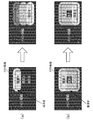
境界近傍光源の検出方法について、図3(a)〜3(c)を用いて詳しく説明する。
本実施例では、表示領域設定部101は、第1画像と第2画像(第1画像の画像表示領域と第2画像の画像表示領域)の配列方向における、第1画像と第2画像の中心位置を、第1画像と第2画像の境界の位置として表す境界位置情報を生成する。なお、第1画像と第2画像の中心位置からずれた位置が、第1画像と第2画像の境界の位置として使用されてもよい。
そして、バックライト制御部106は、第1画像が表示される領域と、第2画像が表示される領域と、の両方に光を照射する光源を、境界近傍光源として検出する。
A method for detecting the light source near the boundary will be described in detail with reference to FIGS.
In this embodiment, the display
And the
図3(a)〜3(c)の符号dは、境界の位置から第1画像または第2画像までの距離を示す。本実施例では、第1画像と第2画像の中心位置が境界の位置として使用されるた
め、境界の位置から第1画像までの距離は、境界の位置から第2画像までの距離と等しい。
また、図3(a)〜3(c)の符号K1〜K3は、光源が配置されている位置を示す。
図3(a)〜3(c)に示すように、本実施例では、光源は、画面の領域のうち、当該光源が配置されている位置K1〜K3から半径rの領域に光を照射する。
距離dは、境界の位置と画像表示領域とに基づいて算出することができる。距離dは、境界位置情報に含まれていてもよいし、バックライト制御部106(または他の機能部)が算出してもよい。
位置K1〜K3及び半径rは予め定められている。
バックライト制御部106は、p≦r−d(pは、光源から境界の位置までの距離)を満たす光源を、境界近傍光源として検出する。図3(a)〜3(c)の例では、位置K1の光源は境界近傍光源として検出されず、位置K2,K3の光源は境界近傍光源として検出される。
A symbol d in FIGS. 3A to 3C indicates a distance from the boundary position to the first image or the second image. In this embodiment, since the center position of the first image and the second image is used as the boundary position, the distance from the boundary position to the first image is equal to the distance from the boundary position to the second image.
Moreover, the code | symbol K1-K3 of Fig.3 (a)-3 (c) shows the position where the light source is arrange | positioned.
As shown in FIGS. 3A to 3C, in this embodiment, the light source irradiates light from a position K <b> 1 to K <b> 3 where the light source is arranged to a region of radius r in the screen region. .
The distance d can be calculated based on the boundary position and the image display area. The distance d may be included in the boundary position information, or may be calculated by the backlight control unit 106 (or other functional unit).
The positions K1 to K3 and the radius r are predetermined.
The
なお、境界近傍光源の検出方法は上記方法に限らない。例えば、光源が光を照射する領域(照射領域)を表す照射領域情報が予め用意されていてもよい。そして、照射領域情報が表す照射領域と、表示領域情報が表す画像表示領域と、に基づいて、第1画像が表示される領域と、第2画像が表示される領域と、の両方に光を照射する光源が、境界近傍光源として検出されてもよい。 In addition, the detection method of a boundary vicinity light source is not restricted to the said method. For example, irradiation area information representing an area (irradiation area) where the light source emits light may be prepared in advance. Based on the irradiation region represented by the irradiation region information and the image display region represented by the display region information, light is emitted to both the region where the first image is displayed and the region where the second image is displayed. The illuminating light source may be detected as a boundary vicinity light source.
図17(a)〜17(c)及び図4(a)〜4(c)を用いて、本実施例の効果について詳しく説明する。
図17(a)〜17(c)は、従来の画像表示装置の動作の一例を示し、図4(a)〜4(c)は、本実施例に係る画像表示装置の動作の一例を示す。図17(a)〜17(c)及び図4(a)〜4(c)では、左側に現フレームの情報が記載されており、右側に次フレーム(現フレームの次のフレーム)の情報が記載されている。
図17(a)と図4(a)は、表示対象画像(合成画像)を示す。図17(a)と図4(a)では、画像データの輝度値の増加に伴って色が黒から白に変化するように、画像データの輝度値が色で表現されている。図17(a)と図4(a)では、合成画像に、第1画像と第2画像とが配置されている。
図17(b)と図4(b)は、各光源(分割領域)の発光輝度を示す。図17(b)と図4(b)では、水平方向5個×垂直方向5個の合計25個の光源(分割領域)が配置されている。図17(b)と図4(b)では、発光輝度の増加に伴って色が黒から白に変化するように、発光輝度が色で表現されている。3列目の光源が、第1画像が表示される領域と第2画像が表示される領域との両方に光を照射する境界近傍光源である。
図17(c)と図4(c)は、表示画像を示す。図17(c)と図4(c)では、表示輝度の増加に伴って色が黒から白に変化するように、表示輝度が色で表現されている。
なお、光源の配置及び数は特に限定されない。例えば、光源の数は25個より多くても少なくてもよい。また、複数の光源は千鳥格子状に配置されていてもよい。
The effects of the present embodiment will be described in detail with reference to FIGS. 17 (a) to 17 (c) and FIGS. 4 (a) to 4 (c).
17A to 17C show an example of the operation of the conventional image display device, and FIGS. 4A to 4C show an example of the operation of the image display device according to the present embodiment. . In FIGS. 17 (a) to 17 (c) and FIGS. 4 (a) to 4 (c), information on the current frame is written on the left side, and information on the next frame (next frame of the current frame) is shown on the right side. Have been described.
FIG. 17A and FIG. 4A show display target images (composite images). In FIG. 17A and FIG. 4A, the luminance value of the image data is expressed in color so that the color changes from black to white as the luminance value of the image data increases. In FIG. 17A and FIG. 4A, the first image and the second image are arranged in the composite image.
FIG. 17B and FIG. 4B show the light emission luminance of each light source (divided region). In FIG. 17B and FIG. 4B, a total of 25 light sources (divided regions) of 5 in the horizontal direction and 5 in the vertical direction are arranged. In FIGS. 17B and 4B, the light emission luminance is expressed in color so that the color changes from black to white as the light emission luminance increases. The light source in the third column is a near-boundary light source that emits light to both the area where the first image is displayed and the area where the second image is displayed.
FIG. 17C and FIG. 4C show display images. In FIG. 17C and FIG. 4C, the display luminance is expressed in color so that the color changes from black to white as the display luminance increases.
The arrangement and number of light sources are not particularly limited. For example, the number of light sources may be more or less than 25. The plurality of light sources may be arranged in a staggered pattern.
図17(a)では、現フレームから次フレームにかけて、第1画像が変化している。そして、第1画像の変化によって、境界近傍光源が配置されている分割領域における合成画像が、暗い画像から、暗い領域と明るい領域とを含む画像に変化している。
従来の画像表示装置では、図17(b)に示すように、境界近傍光源が配置されている分割領域における合成画像の明るさ(特徴量)の変化に応じて、境界近傍光源の発光輝度が大きく変化する。
そのため、従来の画像表示装置では、図17(c)に示すように、第1画像の変化に伴って、第2画像の表示輝度が大きく変化してしまう。具体的には、第2画像の黒浮きの度合いが大きく変化してしまう。このような表示輝度の変化は、ちらつき(フリッカ)として知覚されてしまう。
In FIG. 17A, the first image changes from the current frame to the next frame. Then, due to the change in the first image, the composite image in the divided area where the light source near the boundary is arranged is changed from a dark image to an image including a dark area and a bright area.
In the conventional image display device, as shown in FIG. 17B, the light emission luminance of the light source near the boundary varies according to the change in the brightness (feature amount) of the composite image in the divided area where the light source near the boundary is arranged. It changes a lot.
For this reason, in the conventional image display device, as shown in FIG. 17C, the display brightness of the second image greatly changes as the first image changes. Specifically, the degree of black floating in the second image changes greatly. Such a change in display luminance is perceived as flicker.
図4(a)でも、図17(a)と同様に、現フレームから次フレームにかけて、第1画像が変化している。そして、第1画像の変化によって、境界近傍光源が配置されている分割領域における合成画像が、暗い画像から、暗い領域と明るい領域とを含む画像に変化している。
しかしながら、本実施例では、図4(b)に示すように、境界近傍光源が配置されている分割領域における合成画像の明るさ(特徴量)の変化に応じた境界近傍光源の発光輝度の変化が、従来の画像表示装置に比べて抑制される。具体的には、境界近傍光源が配置されている分割領域における合成画像の明るさが低下した場合に、境界近傍光源の発光輝度が低下しすぎないように、境界近傍光源の発光輝度が制御される。
それにより、本実施例では、図4(c)に示すように、第1画像の変化に伴う第2画像の表示輝度の変化を低減することができる。具体的には、第2画像の黒浮きの変化を低減することができる。
Also in FIG. 4A, the first image changes from the current frame to the next frame, as in FIG. 17A. Then, due to the change in the first image, the composite image in the divided area where the light source near the boundary is arranged is changed from a dark image to an image including a dark area and a bright area.
However, in this embodiment, as shown in FIG. 4B, a change in emission luminance of the light source near the boundary in accordance with a change in brightness (feature amount) of the composite image in the divided area where the light source near the boundary is arranged. However, it is suppressed compared with the conventional image display apparatus. Specifically, when the brightness of the combined image in the divided area where the light source near the boundary is reduced, the light emission luminance of the light source near the boundary is controlled so that the light emission luminance of the light source near the boundary does not decrease excessively. The
Thereby, in the present embodiment, as shown in FIG. 4C, the change in the display luminance of the second image accompanying the change in the first image can be reduced. Specifically, it is possible to reduce the change in the black float of the second image.
さらに本実施例では、非境界近傍光源の発光輝度は広い範囲で制御される。具体的には、非境界近傍光源が配置されている分割領域における合成画像の明るさが低下した場合に、非境界近傍光源の発光輝度が十分に低下するように、非境界近傍光源の発光輝度が制御される。それにより、第1画像と第2画像の境界から離れた領域において、黒浮きを十分に低減することができる。そして、第1画像と第2画像の境界から離れた領域において、ダイナミックレンジが広い表示画像やコントラストが高い表示画像を得ることができる。 Furthermore, in this embodiment, the light emission luminance of the non-boundary light source is controlled in a wide range. Specifically, when the brightness of the composite image in the divided area where the non-boundary light source is arranged decreases, the light emission brightness of the non-boundary light source decreases sufficiently so that the light emission brightness of the non-boundary light source decreases sufficiently. Is controlled. Thereby, in the area | region away from the boundary of a 1st image and a 2nd image, a black float can fully be reduced. In a region away from the boundary between the first image and the second image, a display image with a wide dynamic range and a display image with a high contrast can be obtained.
従来の画像表示装置と本実施例に係る画像表示装置の動作の具体例について、図6(a),6(b)を用いて説明する。図6(a),6(b)は、暗いメイン画像上にOSD画像が重畳された合成画像(表示対象画像)を表示する場合の例を示す。図6(a)は、従来の画像表示装置の動作の具体例を示し、図6(b)は、本実施例に係る画像表示装置の動作の具体例を示す。
図6(a),6(b)のOSD画像には、3つの項目1〜3が示されており、ユーザ操作に応じて項目1〜3のいずれかが選択される。選択項目(選択されている項目)の輝度値として、他の項目よりも高い値が設定される。
図6(a),6(b)は、選択項目が項目1から項目3へ遷移する例を示している。
A specific example of the operation of the conventional image display apparatus and the image display apparatus according to the present embodiment will be described with reference to FIGS. 6 (a) and 6 (b). 6A and 6B show an example in which a composite image (display target image) in which an OSD image is superimposed on a dark main image is displayed. 6A shows a specific example of the operation of the conventional image display apparatus, and FIG. 6B shows a specific example of the operation of the image display apparatus according to the present embodiment.
Three
FIGS. 6A and 6B show an example in which the selected item transitions from
図6(a)に示すように、従来の画像表示装置では、選択項目周辺に配置されている光源の発光輝度が高い値に制御され、それ以外の光源の発光輝度が低い値に制御される。そのため、メイン画像の端部(OSD画像側の端部)の黒浮きが視認され、黒浮きが視認される領域がユーザ操作に応じて遷移する。そして、従来の画像表示装置では、黒浮きの変化が大きい。このように、従来の画像表示装置では、黒浮きの変化が大きく、且つ、黒浮きの変化がユーザ操作に応じて遷移するため、黒浮きの変化が妨害として知覚されやすい。 As shown in FIG. 6A, in the conventional image display device, the light emission luminance of the light sources arranged around the selection item is controlled to a high value, and the light emission luminances of other light sources are controlled to a low value. . Therefore, the black float at the end of the main image (the end on the OSD image side) is visually recognized, and the area where the black float is visually recognized transitions according to the user operation. And in the conventional image display apparatus, the change of black floating is large. As described above, in the conventional image display device, the change in the black float is large, and the change in the black float transitions according to the user operation. Therefore, the change in the black float is easily perceived as an obstacle.
図6(b)に示すように、本実施例では、メイン画像とOSD画像の境界の近傍に配置されている光源の発光輝度の変化が抑制されるため、黒浮きの変化を抑制することができる。その結果、黒浮きの変化を知覚し難くすることができる。 As shown in FIG. 6B, in this embodiment, since the change in the light emission luminance of the light source arranged in the vicinity of the boundary between the main image and the OSD image is suppressed, the change in the black float can be suppressed. it can. As a result, it is possible to make it difficult to perceive changes in black float.
従来技術の課題と本実施例の効果について補足する。
一般的に、光源の発光輝度が急激に変化すると、黒浮きの度合い変化が妨害として視認されてしまう。
従来技術として、光源の発光輝度の時間変化が抑制されるように、各光源の発光輝度を制御する技術が提案されている。そのような従来技術を用いれば、黒浮きの変化を視認し難くすることができる。しかしながら、そのような従来技術を用いると、光源の発光輝度を十分に高めることができず、表示画像の画質劣化が生じてしまうことがある。
なお、画像処理によって表示輝度を高めることはできる。しかしながら、画素値には上限値があるため、画像処理を行っても十分な表示輝度が得られず、表示画像の画質劣化が生じてしまうことがある。
It supplements about the subject of a prior art and the effect of a present Example.
In general, when the light emission luminance of the light source changes abruptly, a change in the degree of black float is visually recognized as an interference.
As a conventional technique, a technique for controlling the light emission luminance of each light source has been proposed so that the temporal change of the light emission luminance of the light source is suppressed. By using such a conventional technique, it is possible to make it difficult to visually recognize the change in the black float. However, when such a conventional technique is used, the light emission luminance of the light source cannot be sufficiently increased, and the image quality of the display image may be deteriorated.
Note that the display luminance can be increased by image processing. However, since the pixel value has an upper limit value, sufficient display luminance cannot be obtained even if image processing is performed, and the image quality of the display image may be deteriorated.
合成画像データではない画像データ(1つの画像のみを表す画像データ)では、時間的及び空間的な画像の相関(類似度)が高い。そのため、そのような画像データに基づく画像を表示する際に光源の発光輝度の急激な変化が頻繁に生じるとは考えにくい。
しかしながら、合成画像データでは、合成画像に配置されている複数の画像間の相関が低く、時間的及び空間的な画像の相関も低い。そのため、合成画像データに基づく画像を表示する際に光源の発光輝度の急激な変化が高い頻度で生じると考えられる。具体的には、第1画像と第2画像の境界の近傍に配置されている光源の発光輝度の急激な変化が高い頻度で生じると考えられる。
In image data that is not composite image data (image data representing only one image), the correlation (similarity) between temporal and spatial images is high. For this reason, when displaying an image based on such image data, it is unlikely that rapid changes in the light emission luminance of the light source frequently occur.
However, in the composite image data, the correlation between a plurality of images arranged in the composite image is low, and the correlation between temporal and spatial images is also low. For this reason, it is considered that when the image based on the composite image data is displayed, a rapid change in the light emission luminance of the light source occurs frequently. Specifically, it is considered that a rapid change in the light emission luminance of the light source arranged in the vicinity of the boundary between the first image and the second image occurs at a high frequency.
そこで、本実施例では、合成画像データに基づく画像を表示する際に、境界近傍光源の発光輝度の変動を、非境界近傍光源に比べて抑制する。それにより、第1画像と第2画像の境界の近傍における表示輝度の変動を、表示画像のダイナミックレンジやコントラストの低下を抑制しつつ、抑制することができる。 Therefore, in this embodiment, when an image based on the composite image data is displayed, fluctuations in the emission luminance of the light source near the boundary are suppressed as compared with the light source near the non-boundary. Thereby, the fluctuation | variation of the display brightness | luminance in the vicinity of the boundary of a 1st image and a 2nd image can be suppressed, suppressing the fall of the dynamic range of a display image, or contrast.
以上述べたように、本実施例によれば、多画像表示時に従来のローカルディミング制御を行うことによって生じる表示画像の画質劣化を、表示画像のダイナミックレンジやコントラストの低下を抑制しつつ、抑制することができる。 As described above, according to the present embodiment, image quality deterioration of a display image caused by performing conventional local dimming control during multi-image display is suppressed while suppressing a decrease in dynamic range and contrast of the display image. be able to.
なお、境界近傍光源の検出方法は、上述した方法に限らない。
例えば、第1画像と第2画像の境界の位置までの距離が第1閾値以下である光源が、境界近傍光源として検出されてもよい。
また、境界の位置よりも第1画像が表示される領域の側に配置されている境界近傍光源(第1光源)と、境界の位置よりも第2画像が表示される領域の側に配置されている境界近傍光源(第2光源)と、が互いに異なる閾値を用いて検出されてもよい。第1光源は、境界の位置よりも第1画像が表示される領域の側に配置されており、且つ、境界の位置までの距離が第2閾値以下である光源である。第2光源は、境界の位置よりも第2画像が表示される領域の側に配置されており、且つ、境界の位置までの距離が第3閾値以下である光源である。第2閾値として大きい値を使用し、第3閾値として小さい値を使用すれば、第1画像の特徴量の変化が第2画像の表示輝度に及ぼす影響を低減することができる。また、第2閾値として大きい値を使用し、第3閾値として小さい値を使用すれば、境界の位置よりも第2画像が表示される領域の側に配置されている光源の多くを、非境界近傍光源として使用することができる。その結果、第2画像のダイナミックレンジがより広い表示画像や第2画像のコントラストがより高い表示画像を得ることができる。
なお、第1閾値、第2閾値、及び、第3閾値はメーカー等によって予め定められていてもよいし、そうでなくてもよい。例えば、第1閾値、第2閾値、及び、第3閾値の少なくともいずれかは、ユーザ操作、複数の入力画像データ、画像表示装置の設置環境、等に応じて決定されてもよい。
なお、第1輝度は非境界近傍光源に対してのみ取得されてもよいし、第2輝度は境界近傍光源に対してのみ取得されてもよい。
In addition, the detection method of a boundary vicinity light source is not restricted to the method mentioned above.
For example, a light source whose distance to the position of the boundary between the first image and the second image is not more than a first threshold value may be detected as a light source near the boundary.
Also, a light source near the boundary (first light source) disposed on the side of the region where the first image is displayed with respect to the boundary position, and a region on the side of the region where the second image is displayed with respect to the boundary position. The boundary vicinity light source (second light source) may be detected using different threshold values. The first light source is a light source that is disposed on the side of the region where the first image is displayed with respect to the boundary position, and the distance to the boundary position is equal to or less than the second threshold value. The second light source is a light source that is disposed on the side of the region where the second image is displayed with respect to the boundary position, and whose distance to the boundary position is equal to or less than a third threshold value. If a large value is used as the second threshold value and a small value is used as the third threshold value, it is possible to reduce the influence of the change in the feature amount of the first image on the display luminance of the second image. Further, if a large value is used as the second threshold value and a small value is used as the third threshold value, most of the light sources arranged on the side of the region where the second image is displayed rather than the boundary position are non-boundary. It can be used as a near light source. As a result, a display image with a wider dynamic range of the second image and a display image with a higher contrast of the second image can be obtained.
Note that the first threshold value, the second threshold value, and the third threshold value may or may not be predetermined by a manufacturer or the like. For example, at least one of the first threshold value, the second threshold value, and the third threshold value may be determined according to a user operation, a plurality of input image data, an installation environment of the image display device, and the like.
Note that the first luminance may be acquired only for the non-boundary light source, and the second luminance may be acquired only for the boundary light source.
なお、境界近傍光源の目標輝度の決定方法は、上述した方法に限らない。
例えば、境界近傍光源の目標状態は、以下の条件1,2を満たすように決定されてもよい。
条件1:境界近傍光源から境界の位置までの距離が短いほど、当該境界近傍光源の目標輝度が、当該境界近傍光源に対して取得された特徴量に対応付けられている第2輝度に近い。
条件2:境界近傍光源から境界の位置までの距離が長いほど、当該境界近傍光源の目標輝度が、当該境界近傍光源に対して取得された特徴量に対応付けられている第1輝度に近い。
このような目標輝度は、境界近傍光源に対して取得された特徴量に対応付けられている第1輝度と第2輝度とを当該境界近傍光源から境界の位置までの距離に応じた重みで重みづけ合成することにより、決定することができる。
Note that the method for determining the target luminance of the light source near the boundary is not limited to the method described above.
For example, the target state of the light source near the boundary may be determined so as to satisfy the following
Condition 1: The shorter the distance from the light source near the boundary to the position of the boundary, the closer the target luminance of the light source near the boundary is to the second luminance associated with the feature amount acquired for the light source near the boundary.
Condition 2: The longer the distance from the light source near the boundary to the position of the boundary, the closer the target luminance of the light source near the boundary is to the first luminance associated with the feature amount acquired for the light source near the boundary.
Such target luminance is obtained by weighting the first luminance and the second luminance associated with the feature amount acquired for the light source near the boundary with a weight according to the distance from the light source near the boundary to the position of the boundary. It can be determined by adding and synthesizing.
重みづけ合成によって境界近傍光源の目標輝度を決定する場合の例を図5(a)〜5(c)に示す。図5(a)〜5(c)では、左側に現フレームの情報が記載されており、右側に次フレームの情報が記載されている。
図5(a)は、表示対象画像(合成画像)を示す。図5(a)は、図4(a)と同じである。図5(b)は、各光源(分割領域)の発光輝度を示す。2〜4列目の光源が、第1画像が表示される領域と第2画像が表示される領域との両方に光を照射する境界近傍光源である。図5(c)は、表示画像を示す。
FIGS. 5A to 5C show examples in which the target luminance of the light source near the boundary is determined by weighting synthesis. 5A to 5C, information on the current frame is described on the left side, and information on the next frame is described on the right side.
FIG. 5A shows a display target image (composite image). FIG. 5A is the same as FIG. FIG. 5B shows the light emission luminance of each light source (divided region). The light sources in the second to fourth columns are near-boundary light sources that irradiate both the area where the first image is displayed and the area where the second image is displayed. FIG. 5C shows a display image.
ここでは、境界近傍光源に対して取得された特徴量に対応付けられている第1輝度と第2輝度とを当該境界近傍光源から境界の位置までの距離に応じた重みで重みづけ合成することにより、当該境界近傍光源の目標輝度が決定される。
そのため、図5(b)では、3列目の光源と4列目の光源に対しては現フレームの特徴量として同じ値が取得されるが、4列目の光源の発光輝度は、3列目の光源の発光輝度よりも低い値に制御されている。
そして、図5(c)に示すように、重みづけ合成によって境界近傍光源の目標輝度を決定する構成においても、第1画像と第2画像の境界の近傍における表示輝度の変化を低減することができる。また、図5(c)に示すように、重みづけ合成によって境界近傍光源の目標輝度を決定することにより、境界の近傍の領域と境界から離れた領域との間での表示輝度の急激な変化を抑制することができる。
Here, the first luminance and the second luminance associated with the feature amount acquired for the light source near the boundary are weighted and synthesized with a weight according to the distance from the light source near the boundary to the position of the boundary. Thus, the target luminance of the boundary vicinity light source is determined.
Therefore, in FIG. 5B, the same value is acquired as the feature amount of the current frame for the light source in the third column and the light source in the fourth column, but the emission luminance of the light source in the fourth column is 3 columns. It is controlled to a value lower than the light emission luminance of the eye light source.
As shown in FIG. 5C, even in the configuration in which the target brightness of the light source near the boundary is determined by weighted synthesis, the change in display brightness near the boundary between the first image and the second image can be reduced. it can. In addition, as shown in FIG. 5C, by rapidly determining the target luminance of the light source near the boundary by weighting synthesis, the display luminance changes rapidly between the region near the boundary and the region away from the boundary. Can be suppressed.
<実施例2>
以下、本発明の実施例2に係る画像表示装置及びその制御方法について、図面を参照して説明する。
実施例1では、画像表示装置が、複数の入力画像データを外部から取得し、複数の入力画像データに基づいて合成画像データを生成する例を説明した。また、実施例1では、画像表示装置が、ユーザ操作に応じて表示領域情報と境界位置情報を生成する例を説明した。
本実施例では、画像表示装置が、合成画像データ、表示領域情報、及び、境界位置情報を外部から取得する例を説明する。
外部から取得される表示領域情報は、例えば、外部装置(例えばPC)内で動作するマルチウィンドウOSのウィンドウ位置情報、外部装置内で動作するウェブブラウザや画像ビューアなどが管理している表示位置情報、等である。
<Example 2>
Hereinafter, an image display apparatus and a control method thereof according to Embodiment 2 of the present invention will be described with reference to the drawings.
In the first embodiment, an example has been described in which the image display apparatus acquires a plurality of input image data from the outside and generates composite image data based on the plurality of input image data. Further, in the first embodiment, the example in which the image display device generates the display area information and the boundary position information according to the user operation has been described.
In the present embodiment, an example will be described in which the image display apparatus acquires composite image data, display area information, and boundary position information from the outside.
Display area information acquired from the outside includes, for example, window position information of a multi-window OS that operates in an external apparatus (for example, a PC), display position information that is managed by a web browser, an image viewer, or the like that operates in the external apparatus. , Etc.
図7は、本実施例に係る画像表示装置の機能構成の一例を示すブロック図である。
図7において、実施例1(図1)と同じ機能部には実施例1と同じ符号を付し、その説明は省略する。
FIG. 7 is a block diagram illustrating an example of a functional configuration of the image display apparatus according to the present embodiment.
7, the same reference numerals as those in the first embodiment are assigned to the same functional units as those in the first embodiment (FIG. 1), and the description thereof is omitted.
画像表示装置の外部から取得された合成画像データは、特徴量取得部103と画像補正部107に入力される。
表示領域設定部201は、画像表示装置の外部から表示領域情報と境界位置情報を取得する。そして、表示領域設定部201は、表示領域情報と境界位置情報をバックライト制御部106へ出力する。表示領域情報と境界位置情報の少なくとも一方は、例えば、合成画像データのヘッダ領域に重畳されている。そして、表示領域設定部201は、表示領域
情報と境界位置情報の少なくとも一方を、合成画像データから抽出する。
なお、表示領域情報と境界位置情報の少なくとも一方は、合成画像データから独立して画像表示装置に入力されてもよい。例えば、表示領域情報と境界位置情報の少なくとも一方は、専用の通信線を用いて画像表示装置に入力されてもよい。
なお、実施例1で述べたように、表示領域情報はバックライト制御部106で使用されないことがある。そのため、表示領域設定部201は、境界位置情報を取得すればよく、表示領域情報を取得しなくてもよい。
なお、境界位置情報は、画像表示装置の外部から取得されなくてもよい。表示領域設定部201は、表示領域情報が表す画像表示領域に基づいて境界位置情報を生成してもよい。
The composite image data acquired from the outside of the image display device is input to the feature
The display
Note that at least one of the display area information and the boundary position information may be input to the image display device independently from the composite image data. For example, at least one of the display area information and the boundary position information may be input to the image display device using a dedicated communication line.
As described in the first embodiment, the display area information may not be used by the
The boundary position information may not be acquired from the outside of the image display device. The display
本実施例では、実施例1と同様に、第1画像と第2画像の境界の近傍に配置されている光源が、境界近傍光源として検出される。そして、非境界近傍光源の発光輝度が、当該非境界近傍光源に対して取得された特徴量に対応付けられている第1輝度(第1対応関係の発光輝度)に制御される。また、境界近傍光源の発光輝度が、当該境界近傍光源に対して取得された特徴量に対応付けられている第2輝度(第2対応関係の発光輝度)に制御される。
その結果、実施例1と同様に、複数の画像を並べて表示する多画像表示時に従来のローカルディミング制御を行うことによって生じる表示画像の画質劣化を、表示画像のダイナミックレンジやコントラストの低下を抑制しつつ、抑制することができる。
In the present embodiment, as in the first embodiment, a light source arranged in the vicinity of the boundary between the first image and the second image is detected as a light source near the boundary. Then, the light emission luminance of the non-boundary light source is controlled to the first luminance (the light emission luminance of the first correspondence relationship) associated with the feature amount acquired for the non-boundary light source. Further, the light emission luminance of the light source near the boundary is controlled to the second luminance (light emission luminance of the second correspondence relationship) associated with the feature amount acquired for the light source near the boundary.
As a result, as in the first embodiment, the deterioration in the display image quality caused by the conventional local dimming control during multi-image display in which a plurality of images are displayed side by side is suppressed, and the decrease in the dynamic range and contrast of the display image is suppressed. However, it can be suppressed.
従来の画像表示装置と本実施例に係る画像表示装置の動作の具体例について、図8(a),8(b)を用いて説明する。図8(a),8(b)は、暗い背景画像上にビューア画像が重畳された合成画像(表示対象画像)を表示する場合の例を示す。図8(a)は、従来の画像表示装置の動作の具体例を示し、図8(b)は、本実施例に係る画像表示装置の動作の具体例を示す。
ビューア画像の領域には、動画像が表示されたり、複数の画像(動画像や静止画像)が切り替えられて表示されたりする。そのため、ビューア画像の輝度値は頻繁に変化する。
図8(a),8(b)は、ビューア画像の輝度値が増加する例を示している。
A specific example of the operation of the conventional image display apparatus and the image display apparatus according to the present embodiment will be described with reference to FIGS. 8 (a) and 8 (b). FIGS. 8A and 8B show an example in which a composite image (display target image) in which a viewer image is superimposed on a dark background image is displayed. FIG. 8A shows a specific example of the operation of the conventional image display apparatus, and FIG. 8B shows a specific example of the operation of the image display apparatus according to the present embodiment.
In the viewer image area, a moving image is displayed, or a plurality of images (moving images and still images) are switched and displayed. For this reason, the luminance value of the viewer image changes frequently.
8A and 8B show an example in which the luminance value of the viewer image increases.
図8(a)に示すように、従来の画像表示装置では、ビューア画像の明るさの変化に応じて、ビューア画像が表示される領域の近傍に配置されている光源の発光輝度が大きく変化する。そのため、ビューア画像の明るさの変化に応じて、背景画像の端部(ビューア画像側の端部)の黒浮きの度合いが大きく変化する。このように、従来の画像表示装置では、黒浮きの変化が大きいため、黒浮きの変化が妨害として知覚されやすい。 As shown in FIG. 8A, in the conventional image display device, the light emission luminance of the light source arranged in the vicinity of the area where the viewer image is displayed changes greatly according to the change in the brightness of the viewer image. . For this reason, the degree of black float at the end of the background image (the end on the viewer image side) changes greatly according to the change in the brightness of the viewer image. As described above, in the conventional image display device, since the change in the black float is large, the change in the black float is easily perceived as an interference.
図8(b)に示すように、本実施例では、背景画像とビューア画像の境界の近傍に配置されている光源の発光輝度の変化が抑制されるため、黒浮きの変化を抑制することができる。その結果、黒浮きの変化を知覚し難くすることができる。 As shown in FIG. 8B, in this embodiment, the change in the light emission luminance of the light source arranged in the vicinity of the boundary between the background image and the viewer image is suppressed. it can. As a result, it is possible to make it difficult to perceive changes in black float.
以上述べたように、本実施例によれば、合成画像データ、表示領域情報、及び、境界位置情報が画像表示装置の外部から取得される場合において、実施例1と同様の効果を得ることができる。 As described above, according to the present embodiment, the same effect as that of the first embodiment can be obtained when the composite image data, the display area information, and the boundary position information are acquired from the outside of the image display device. it can.
<実施例3>
以下、本発明の実施例3に係る画像表示装置及びその制御方法について、図面を参照して説明する。
図9,10は、本実施例に係る画像表示装置の機能構成の一例を示すブロック図である。図9は、複数の入力画像データが画像表示装置の外部から取得される場合の例を示し、図10は、合成画像データ、表示領域情報、及び、境界位置情報が画像表示装置の外部か
ら取得される場合の例を示す。
図9,10において、実施例1,2(図1,7)と同じ機能部には実施例1,2と同じ符号を付し、その説明は省略する。
<Example 3>
Hereinafter, an image display apparatus and a control method thereof according to Embodiment 3 of the present invention will be described with reference to the drawings.
9 and 10 are block diagrams illustrating an example of a functional configuration of the image display apparatus according to the present embodiment. FIG. 9 shows an example in which a plurality of input image data is acquired from the outside of the image display device, and FIG. 10 shows that composite image data, display area information, and boundary position information are acquired from the outside of the image display device. An example will be shown.
9 and 10, the same functional parts as those in the first and second embodiments (FIGS. 1 and 7) are denoted by the same reference numerals as those in the first and second embodiments, and the description thereof is omitted.
特徴量取得部303は、実施例1,2の特徴量取得部103と同じ処理を実行する。
さらに、特徴量取得部303は、第1取得処理と第2取得処理を実行する。第1取得処理は、第1画像の特徴量である第1特徴量を取得する処理である。第2取得処理は、第2画像の特徴量である第2特徴量を取得する処理である。特徴量取得部303は、第1特徴量と第2特徴量を、特徴量比較部310へ出力する。
The feature
Further, the feature
第1特徴量と第2特徴量の取得方法について説明する。
特徴量取得部303は、表示領域設定部101または表示領域設定部201から表示領域情報を取得する。そして、特徴量取得部303は、各光源に対して取得した特徴量と、表示領域情報と、に基づいて、第1特徴量と第2特徴量を取得する。
本実施例では、特徴量取得部303は、表示領域情報に基づいて、複数の分割領域の中から第1分割領域と第2分割領域を検出する。第1分割領域は、第1画像が表示され、且つ、第2画像が表示されない分割領域である。第2分割領域は、第1画像が表示されず、且つ、第2画像が表示される分割領域である。そして、特徴量取得部303は、第1分割領域における合成画像(表示対象画像)の特徴量を、第1特徴量として取得する。複数の第1分割領域が存在する場合には、特徴量取得部303は、各第1分割領域における合成画像の特徴量を代表する代表特徴量を、第1特徴量として取得する。また、特徴量取得部303は、第2分割領域における合成画像(表示対象画像)の特徴量を、第2特徴量として取得する。複数の第2分割領域が存在する場合には、特徴量取得部303は、各第2分割領域における合成画像の特徴量を代表する代表特徴量を、第2特徴量として取得する。代表特徴量は、特徴量の最大値、最小値、平均値、最頻値、中間値、等である。代表特徴量は、特徴量の平均値または最頻値であることが好ましい。
A method for acquiring the first feature value and the second feature value will be described.
The feature
In the present embodiment, the feature
なお、第1取得処理と第2取得処理の少なくとも一方は、特徴量取得部303とは異なる機能部によって実行されてもよい。
なお、第1特徴量と第2特徴量との取得方法は、上記方法に限らない。例えば、第1画像を表す画像データから、第1特徴量が取得され、第2画像を表す画像データから、第2特徴量が取得されてもよい。第1画像を表す画像データ、及び、第2画像を表す画像データは、合成画像データから抽出されてもよいし、画像表示装置の外部などから取得されてもよい。
なお、第1特徴量と第2特徴量は、上記特徴量に限らない。例えば、第1特徴量は、第1画像全体の画素値(又は輝度値)のヒストグラムや代表値であってもよい。第2特徴量は、第2画像全体の画素値(又は輝度値)のヒストグラムや代表値であってもよい。
なお、第1分割領域と第2分割領域は、上記分割領域に限らない。例えば、少なくとも第1画像が表示される分割領域が、第1分割領域として検出されてもよい。少なくとも第2画像が表示される分割領域が、第2分割領域として検出されてもよい。そして、第1画像と第2画像の両方が表示される分割領域が、第1分割領域及び第2分割領域として検出されてもよい。第1画像が表示され、且つ、第1画像の表示サイズが第2画像の表示サイズよりも大きい分割領域が、第1分割領域として検出されてもよい。第2画像が表示され、且つ、第2画像の表示サイズが第1画像の表示サイズよりも大きい分割領域が、第2分割領域として検出されてもよい。
Note that at least one of the first acquisition process and the second acquisition process may be executed by a functional unit different from the feature
In addition, the acquisition method of a 1st feature-value and a 2nd feature-value is not restricted to the said method. For example, the first feature amount may be acquired from the image data representing the first image, and the second feature amount may be acquired from the image data representing the second image. The image data representing the first image and the image data representing the second image may be extracted from the composite image data, or may be acquired from outside the image display device.
Note that the first feature value and the second feature value are not limited to the above feature values. For example, the first feature amount may be a histogram of pixel values (or luminance values) of the entire first image or a representative value. The second feature amount may be a histogram or a representative value of pixel values (or luminance values) of the entire second image.
The first divided area and the second divided area are not limited to the divided areas. For example, a divided area where at least the first image is displayed may be detected as the first divided area. A divided area where at least the second image is displayed may be detected as the second divided area. Then, the divided areas where both the first image and the second image are displayed may be detected as the first divided area and the second divided area. A divided area in which the first image is displayed and the display size of the first image is larger than the display size of the second image may be detected as the first divided area. A divided area in which the second image is displayed and the display size of the second image is larger than the display size of the first image may be detected as the second divided area.
特徴量比較部310は、特徴量取得部303から第1特徴量と第2特徴量を取得し、第1特徴量と第2特徴量との差(絶対値)が第5閾値未満であるか否かを判断する。そして、特徴量比較部310は、第1特徴量と第2特徴量との差が第5閾値以上である場合に、変化抑制指示をバックライト制御部306へ出力する。特徴量比較部310は、第1特徴
量と第2特徴量との差が第5閾値未満である場合には、変化抑制指示をバックライト制御部306へ出力しない。
なお、第5閾値は、メーカー等によって予め定められていてもよいし、そうでなくてもよい。例えば、第5閾値は、ユーザ操作、合成画像に配置されている複数の画像、画像表示装置の設置環境、等に応じて決定されてもよい。
The feature
Note that the fifth threshold value may or may not be determined in advance by a manufacturer or the like. For example, the fifth threshold value may be determined according to a user operation, a plurality of images arranged in the composite image, an installation environment of the image display device, and the like.
特徴量比較部310から変化抑制指示が出力された場合に、バックライト制御部306は、実施例1,2のバックライト制御部106と同じ処理を実行する。従って、第1特徴量と第2特徴量との差が第5閾値以上である場合には、実施例1,2と同様の効果が得られる。
特徴量比較部310から変化抑制指示が出力されなかった場合には、バックライト制御部306は、境界近傍光源を非境界近傍光源とみなして、各光源の目標輝度を決定する。即ち、第1特徴量と第2特徴量との差が第5閾値未満である場合には、バックライト制御部306は、境界近傍光源を非境界近傍光源とみなして、各光源の目標輝度を決定する。本実施例では、特徴量比較部310から変化抑制指示が出力されなかった場合には、バックライト制御部306は、各光源の目標輝度として、第1輝度決定部104から出力された第1輝度を設定する。そして、バックライト制御部306は、各光源の発光輝度を目標輝度に制御する。
When a change suppression instruction is output from the feature
When the change suppression instruction is not output from the feature
図11(a),11(b)を用いて、本実施例の効果について説明する。図11(a)は、第1特徴量と第2特徴量の差が第5閾値未満である場合の例を示し、図11(b)は、第1特徴量と第2特徴量の差が第5閾値以上である場合の例を示す。ここでは、特徴量が、画像の明るさを表し、第1特徴量と第2特徴量の差が、第1画像の明るさと第2画像の明るさとの差を表す場合の例を説明する。 The effects of this embodiment will be described with reference to FIGS. 11 (a) and 11 (b). FIG. 11A shows an example where the difference between the first feature value and the second feature value is less than the fifth threshold value, and FIG. 11B shows the difference between the first feature value and the second feature value. An example in the case of being equal to or greater than the fifth threshold is shown. Here, an example will be described in which the feature amount represents the brightness of the image, and the difference between the first feature amount and the second feature amount represents the difference between the brightness of the first image and the brightness of the second image.
本実施例では、第1特徴量と第2特徴量との差が第5閾値未満である場合には、境界近傍光源が非境界近傍光源とみなされ、境界近傍光源の発光輝度も非境界近傍光源と同様に広い範囲で制御される。
図11(a)に示すように、第1画像と第2画像の明るさが同等である場合には、境界の近傍における表示輝度の変動は知覚され難い。例えば、第1画像と第2画像の両方が明るい画像である場合は、人間の目は明るい表示輝度に順応し、低い表示輝度に対する人間の目の感度は低下する。そのため、第1画像と第2画像の両方が明るい画像である場合は、境界の近傍における表示輝度の変動は知覚され難い。従って、第1画像と第2画像の明るさが同等である場合には、境界近傍光源を非境界近傍光源とみなしても問題は無い。
そして、上述したように、第1特徴量と第2特徴量との差が第5閾値未満である場合には、境界近傍光源の発光輝度も非境界近傍光源と同様に広い範囲で制御される。それにより、第1特徴量と第2特徴量との差が第5閾値未満である場合に、実施例1,2に比べて黒浮きが低減された表示画像を得ることができる。そして、第1特徴量と第2特徴量との差が第5閾値未満である場合に、実施例1,2に比べてダイナミックレンジが広い表示画像や実施例1,2に比べてコントラストが高い表示画像を得ることができる。
In this embodiment, when the difference between the first feature value and the second feature value is less than the fifth threshold value, the light source near the boundary is regarded as a non-boundary light source, and the emission luminance of the light source near the boundary is also near the non-boundary. It is controlled over a wide range like the light source.
As shown in FIG. 11A, when the brightness of the first image and that of the second image are the same, it is difficult to perceive a change in display luminance near the boundary. For example, when both the first image and the second image are bright images, the human eye adapts to bright display luminance, and the sensitivity of the human eye to low display luminance decreases. For this reason, when both the first image and the second image are bright images, it is difficult to perceive a change in display luminance in the vicinity of the boundary. Therefore, when the brightness of the first image is the same as that of the second image, there is no problem even if the light source near the boundary is regarded as a non-boundary light source.
As described above, when the difference between the first feature value and the second feature value is less than the fifth threshold value, the light emission luminance of the light source near the boundary is controlled in a wide range like the light source near the boundary. . Thereby, when the difference between the first feature value and the second feature value is less than the fifth threshold value, it is possible to obtain a display image with reduced black float compared to the first and second embodiments. When the difference between the first feature value and the second feature value is less than the fifth threshold value, the display image has a wider dynamic range than the first and second embodiments and the contrast is higher than those of the first and second embodiments. A display image can be obtained.
図11(b)に示すように、第1画像と第2画像の明るさが大きく異なる場合には、境界の近傍における表示輝度の変動は知覚され易い。
本実施例では、第1特徴量と第2特徴量との差が第5閾値以上である場合には、実施例1,2と同様に、境界近傍光源の発光輝度の変化を抑制する処理が実行される。それにより、第1特徴量と第2特徴量との差が第5閾値以上である場合に、境界の近傍における表示輝度の変化を抑制することができる。
As shown in FIG. 11B, when the brightness of the first image and the second image are greatly different, the display luminance fluctuation in the vicinity of the boundary is easily perceived.
In the present embodiment, when the difference between the first feature value and the second feature value is equal to or greater than the fifth threshold value, the process of suppressing the change in the light emission luminance of the light source near the boundary is performed as in the first and second embodiments. Executed. Thereby, when the difference between the first feature value and the second feature value is equal to or larger than the fifth threshold value, it is possible to suppress a change in display luminance in the vicinity of the boundary.
以上述べたように、本実施例によれば、第1特徴量と第2特徴量との差が第5閾値以上である場合に限って、境界近傍光源の発光輝度の変化を抑制する処理が行われる。そして
、第1特徴量と第2特徴量との差が第5閾値未満である場合には、境界近傍光源が非境界近傍光源とみなされる。それにより、境界の近傍における表示輝度の変化が知覚され易い場合に、実施例1,2と同様の効果を得ることができる。そして、境界の近傍における表示輝度の変化が知覚され難い場合に、実施例1,2よりもダイナミックレンジが広い表示画像や実施例1,2よりもコントラストが高い表示画像を得ることができる。
As described above, according to the present embodiment, the process for suppressing the change in the light emission luminance of the light source near the boundary is performed only when the difference between the first feature value and the second feature value is equal to or greater than the fifth threshold value. Done. If the difference between the first feature value and the second feature value is less than the fifth threshold value, the boundary vicinity light source is regarded as a non-boundary vicinity light source. Thereby, when the change of the display brightness in the vicinity of the boundary is easily perceived, the same effect as in the first and second embodiments can be obtained. When it is difficult to perceive a change in display brightness near the boundary, it is possible to obtain a display image having a wider dynamic range than those of the first and second embodiments and a display image having a higher contrast than those of the first and second embodiments.
なお、本実施例では、第1特徴量と第2特徴量との差が第5閾値未満である場合に、境界近傍光源を非境界近傍光源とみなす例を説明したが、これに限らない。例えば、合成画像(表示対象画像)の変化による境界近傍光源の目標輝度の変化が、非境界近傍光源に比べて、第1特徴量と第2特徴量の差が大きいほど大きく抑制されるように、各光源の目標輝度が決定されてもよい。このような処理は、例えば、第1特徴量と第2特徴量の差に応じた重みで第1輝度と第2輝度を合成した値を、境界近傍光源の目標輝度として設定することにより実現できる。このような処理を行うことにより、より適切な表示画像を得ることができる。具体的には、表示輝度の変化の知覚し易さに応じて、境界の近傍における表示輝度の変化の抑制度合いを連続的(又は段階的)に変更することができる。また、表示輝度の変化の知覚し易さに応じて、境界の近傍における表示画像のダイナミックレンジやコントラストを連続的(又は段階的)に変更することができる。 In the present embodiment, the example in which the light source near the boundary is regarded as the non-boundary light source when the difference between the first feature value and the second feature value is less than the fifth threshold value has been described, but the present invention is not limited thereto. For example, the change in the target luminance of the light source near the boundary due to the change in the composite image (display target image) is more greatly suppressed as the difference between the first feature value and the second feature value is larger than in the non-boundary light source. The target brightness of each light source may be determined. Such processing can be realized, for example, by setting a value obtained by synthesizing the first luminance and the second luminance with a weight according to the difference between the first feature amount and the second feature amount as the target luminance of the light source near the boundary. . By performing such processing, a more appropriate display image can be obtained. Specifically, the degree of suppression of the change in display luminance near the boundary can be changed continuously (or stepwise) according to the ease of perceiving the change in display luminance. Further, the dynamic range and contrast of the display image in the vicinity of the boundary can be changed continuously (or stepwise) according to the ease of perceiving the change in display luminance.
<実施例4>
以下、本発明の実施例4に係る画像表示装置及びその制御方法について、図面を参照して説明する。
本実施例に係る画像表示装置の構成は、実施例1〜3(図1,7,9,10)と同じである。本実施例では、第2対応関係が実施例1〜3と異なる。
<Example 4>
Hereinafter, an image display apparatus and a control method thereof according to Embodiment 4 of the present invention will be described with reference to the drawings.
The configuration of the image display apparatus according to the present embodiment is the same as that of the first to third embodiments (FIGS. 1, 7, 9, and 10). In the present embodiment, the second correspondence relationship is different from those in the first to third embodiments.
本実施例に係る第1対応関係と第2対応関係の一例を図12(a)に示す。図12(a)は、特徴量が8ビットの値(0〜255)である場合の例を示す。本実施例では、特徴量は、画像の明るさを表す。
図12(a)に示すように、本実施例でも、第2対応関係Bにおいて特徴量に対応付けられている発光輝度の範囲RBは、第1対応関係Aにおいて特徴量に対応付けられている発光輝度の範囲RAよりも狭い。
また、図12(a)に示すように、本実施例でも、第2対応関係Bの発光輝度の最低値mBは、第1対応関係Aの発光輝度の最低値mAよりも高い(大きい)。
また、図12(a)に示すように、本実施例でも、大きい特徴量に対応付けられている第1対応関係の発光輝度と第2対応関係の発光輝度との差が、小さい特徴量に対応付けられている第1対応関係の発光輝度と第2対応関係の発光輝度との差よりも小さい。
An example of the first correspondence relationship and the second correspondence relationship according to the present embodiment is shown in FIG. FIG. 12A shows an example in which the feature amount is an 8-bit value (0 to 255). In this embodiment, the feature amount represents the brightness of the image.
As shown in FIG. 12A, also in this embodiment, the emission luminance range RB associated with the feature amount in the second correspondence relationship B is associated with the feature amount in the first correspondence relationship A. It is narrower than the emission luminance range RA.
Also, as shown in FIG. 12A, also in this embodiment, the minimum value mB of the light emission luminance of the second correspondence relationship B is higher (larger) than the minimum value mA of the light emission luminance of the first correspondence relationship A.
Also, as shown in FIG. 12A, also in this embodiment, the difference between the light emission luminance of the first correspondence relationship and the light emission luminance of the second correspondence relationship associated with a large feature amount is a small feature amount. The difference between the light emission luminance of the first correspondence relationship and the light emission luminance of the second correspondence relationship is smaller.
但し、本実施例に係る第2対応関係Bでは、閾値T未満の特徴量に対して、当該特徴量に対応付けられている第1対応関係Aの発光輝度よりも高い発光輝度が対応付けられている。そして、閾値T以上の特徴量に対しては、当該特徴量に対応付けられている第1対応関係Aの発光輝度と同じ発光輝度が対応付けられている。閾値T未満の特徴量は、第4閾値未満の明るさを表し、閾値T以上の特徴量は、第4閾値以上の明るさを表す。 However, in the second correspondence relationship B according to the present embodiment, the light emission luminance higher than the light emission luminance of the first correspondence relationship A associated with the feature amount is associated with the feature amount less than the threshold T. ing. The feature amount equal to or greater than the threshold value T is associated with the same light emission luminance as the light emission luminance of the first correspondence A associated with the feature amount. A feature quantity less than the threshold value T represents brightness less than the fourth threshold value, and a feature quantity greater than or equal to the threshold value T represents brightness greater than or equal to the fourth threshold value.
そのため、本実施例では、境界近傍光源に対して取得された特徴量が閾値T未満の場合に、表示対象画像(合成画像)の変化による境界近傍光源の発光輝度の変化が非境界近傍光源に比べて抑制されるように、境界近傍光源の発光輝度が制御される。その結果、境界の近傍における表示輝度の変化を抑制することができる。
そして、境界近傍光源に対して取得された特徴量が閾値T以上の場合には、非境界近傍光源と同様の方法(基準)で、境界近傍光源の発光輝度が制御される。その結果、黒浮きがより低減された表示画像を得ることができる。また、ダイナミックレンジがより広い表示画像やコントラストがより高い表示画像を得ることができる。さらに、非境界近傍光源
と同様の方法(基準)で境界近傍光源の発光輝度が制御することにより、境界近傍光源の発光輝度をより低い値に制御することができるため、消費電力を低減することができる。
Therefore, in the present embodiment, when the feature amount acquired for the light source near the boundary is less than the threshold value T, the change in the emission luminance of the light source near the boundary due to the change in the display target image (composite image) The emission luminance of the light source near the boundary is controlled so as to be suppressed as compared. As a result, a change in display luminance near the boundary can be suppressed.
When the feature amount acquired for the boundary vicinity light source is equal to or greater than the threshold T, the light emission luminance of the boundary vicinity light source is controlled by the same method (reference) as the non-boundary vicinity light source. As a result, it is possible to obtain a display image in which black floating is further reduced. In addition, a display image with a wider dynamic range and a display image with a higher contrast can be obtained. Furthermore, by controlling the light emission luminance of the light source near the boundary by the same method (reference) as the light source near the non-boundary, the light emission luminance of the light source near the boundary can be controlled to a lower value, thereby reducing power consumption. Can do.
なお、黒浮きや表示輝度の変動は、画像が暗いほど知覚され易く、画像が明るいほど知覚され難い。そのため、境界近傍光源に対して取得された特徴量が閾値T以上の場合には、黒浮きや表示輝度の変動は知覚され難く、非境界近傍光源と同様の方法で境界近傍光源の発光輝度を制御しても問題は無い。
なお、閾値Tや第4閾値は、メーカー等によって予め定められていてもよいし、そうでなくてもよい。例えば、閾値Tや第4閾値は、ユーザ操作、合成画像に配置されている複数の画像、画像表示装置の設置環境、等に応じて決定されてもよい。
Note that the black float and the change in display brightness are more easily perceived as the image is darker and less likely to be perceived as the image is brighter. For this reason, when the feature amount acquired for the light source near the boundary is equal to or greater than the threshold value T, the black float and the change in display luminance are difficult to perceive. There is no problem even if it is controlled.
Note that the threshold value T and the fourth threshold value may or may not be determined in advance by a manufacturer or the like. For example, the threshold value T and the fourth threshold value may be determined according to a user operation, a plurality of images arranged in the composite image, an installation environment of the image display device, and the like.
以上述べたように、本実施例によれば、境界の近傍における表示輝度の変化が知覚され易い場合に、境界の近傍における表示輝度の変化を抑制することができる。そして、境界の近傍における表示輝度の変化が知覚され難い場合に、ダイナミックレンジがより広い表示画像やコントラストがより高い表示画像を得ることができる。 As described above, according to the present embodiment, it is possible to suppress a change in display luminance in the vicinity of the boundary when a change in display luminance in the vicinity of the boundary is easily perceived. When it is difficult to perceive a change in display brightness near the boundary, a display image with a wider dynamic range and a display image with a higher contrast can be obtained.
第2対応関係は上述した対応関係に限らない。例えば、図12(b)に示す対応関係Bが第2対応関係として使用されてもよい。図12(b)では、第1対応関係Aの発光輝度と第2対応関係Bの発光輝度との差が、特徴量(特徴量が表す明るさ)の増加に伴って指数関数的に減少している。図12(a)に示す第2対応関係Bでは、傾き(特徴量の変化に対する境界近傍光源の発光輝度の変化)が、閾値Tで不連続に変化する。そのため、図12(a)に示す第2対応関係Bを使用すると、傾きの切り替わりが妨害として知覚されてしまう虞がある。図12(b)に示す第2対応関係Bでは、傾きが連続的に変化するため、上記妨害が知覚されることを抑制することができる。 The second correspondence relationship is not limited to the correspondence relationship described above. For example, the correspondence relationship B shown in FIG. 12B may be used as the second correspondence relationship. In FIG. 12B, the difference between the light emission luminance of the first correspondence relationship A and the light emission luminance of the second correspondence relationship B decreases exponentially as the feature amount (brightness represented by the feature amount) increases. ing. In the second correspondence relationship B shown in FIG. 12A, the slope (change in the light emission luminance of the light source near the boundary with respect to the change in the feature amount) changes discontinuously with the threshold value T. For this reason, when the second correspondence relationship B shown in FIG. 12A is used, there is a risk that the change of inclination may be perceived as an obstruction. In the second correspondence relationship B shown in FIG. 12B, since the inclination changes continuously, the perception of the disturbance can be suppressed.
<実施例5>
以下、本発明の実施例5に係る画像表示装置及びその制御方法について、図面を参照して説明する。
本実施例に係る画像表示装置の構成は、実施例1〜4(図1,7,9,10)と同じである。本実施例では、バックライト制御部の処理が実施例1〜4と異なる。
<Example 5>
Hereinafter, an image display apparatus and a control method thereof according to Embodiment 5 of the present invention will be described with reference to the drawings.
The configuration of the image display apparatus according to the present embodiment is the same as that of the first to fourth embodiments (FIGS. 1, 7, 9, and 10). In the present embodiment, the processing of the backlight control unit is different from those in the first to fourth embodiments.
本実施例に係るバックライト制御部は、実施例1〜4のバックライト制御部と同様に、各光源の目標輝度を決定する。そして、本実施例に係るバックライト制御部は、複数の境界近傍光源が存在する場合に、各境界近傍光源の目標輝度を、各境界近傍光源に対して決定した目標輝度を代表する代表目標輝度に補正する。その後、本実施例に係るバックライト制御部は、各光源の発光輝度を目標輝度に制御する。代表目標輝度は、目標輝度の最大値、最小値、平均値、最頻値、中間値、等である。表示用画像データ(画像補正部107による画像処理後の画像データ)の画素値が上限値に制限されることを抑制するために、代表目標輝度は、目標輝度の最大値であることが好ましい。 The backlight control unit according to the present embodiment determines the target luminance of each light source in the same manner as the backlight control units according to the first to fourth embodiments. The backlight control unit according to the present embodiment, when there are a plurality of light sources near the boundary, represents the target luminance of each boundary light source that represents the target luminance determined for each light source near the boundary. To correct. Thereafter, the backlight control unit according to the present embodiment controls the light emission luminance of each light source to the target luminance. The representative target brightness is the maximum value, the minimum value, the average value, the mode value, the intermediate value, etc. of the target brightness. In order to suppress the pixel value of the display image data (image data after image processing by the image correction unit 107) from being limited to the upper limit value, the representative target luminance is preferably the maximum value of the target luminance.
図13(a),13(b)を用いて、本実施例の効果について詳しく説明する。
図13(a)は、従来の画像表示装置の表示画像の一例を示し、図13(b)は、本実施例に係る画像表示装置の表示画像の一例を示す。図13(a)では、左側に現フレームの表示画像が示されており、右側に次フレーム(現フレームの次のフレーム)の表示画像が示されている。図13(b)は、現フレームの表示画像を示す。
The effects of this embodiment will be described in detail with reference to FIGS. 13 (a) and 13 (b).
FIG. 13A shows an example of a display image of a conventional image display device, and FIG. 13B shows an example of a display image of the image display device according to the present embodiment. In FIG. 13A, the display image of the current frame is shown on the left side, and the display image of the next frame (next frame of the current frame) is shown on the right side. FIG. 13B shows a display image of the current frame.
実施例1で述べたように、従来の画像表示装置では、合成画像の変化によって境界の近傍における表示輝度が大きく変化してしまう。
さらに、図13(a)の例では、複数の境界近傍光源の発光輝度が不均一であるため、境界の近傍において輝度ムラ(具体的には、不均一な黒浮き)が発生している。このよう
な、不均一な黒浮きは、均一な黒浮きに比べて大きい妨害として知覚されてしまう。光源の発光色を制御する場合には、色ムラが発生し得る。具体的には、複数の境界近傍光源の発光色が不均一である場合に、色ムラが発生してしまう。
本実施例では、複数の境界近傍光源の発光状態は、同じ目標状態(各境界近傍光源の目標状態を代表する代表目標状態)に制御される。それにより、図13(b)に示すように、境界の近傍における輝度ムラや色ムラを抑制することができる。
As described in the first embodiment, in the conventional image display device, the display luminance in the vicinity of the boundary greatly changes due to the change in the composite image.
Further, in the example of FIG. 13A, since the light emission luminance of the light sources near the boundary is nonuniform, luminance unevenness (specifically, nonuniform black floating) occurs in the vicinity of the boundary. Such non-uniform black float is perceived as a large disturbance compared to uniform black float. When the emission color of the light source is controlled, color unevenness may occur. Specifically, color unevenness occurs when the light emission colors of a plurality of light sources near the boundary are not uniform.
In this embodiment, the light emission states of a plurality of light sources near the boundary are controlled to the same target state (representative target state representing the target state of each boundary light source). Accordingly, as shown in FIG. 13B, luminance unevenness and color unevenness in the vicinity of the boundary can be suppressed.
以上述べたように、本実施例によれば、各境界近傍光源の目標状態が同じ目標状態に補正された後に、各光源の発光状態が目標状態に制御される。それにより、境界の近傍における輝度ムラや色ムラを抑制することができる。 As described above, according to the present embodiment, after the target state of each boundary light source is corrected to the same target state, the light emission state of each light source is controlled to the target state. Thereby, luminance unevenness and color unevenness in the vicinity of the boundary can be suppressed.
<実施例6>
以下、本発明の実施例6に係る画像表示装置及びその制御方法について、図面を参照して説明する。
本実施例に係る画像表示装置の構成は、実施例1〜5(図1,7,9,10)と同じである。本実施例では、第1輝度決定部と第2輝度決定部の処理が実施例1〜5と異なる。
<Example 6>
Hereinafter, an image display apparatus and a control method thereof according to Embodiment 6 of the present invention will be described with reference to the drawings.
The configuration of the image display apparatus according to the present embodiment is the same as that of the first to fifth embodiments (FIGS. 1, 7, 9, and 10). In a present Example, the process of a 1st brightness | luminance determination part and a 2nd brightness | luminance determination part differs from Examples 1-5.
第1輝度決定部は、特徴量と発光輝度の対応関係である第1対応関係を表す第1情報(関数やテーブル)を記憶する。第1輝度決定部は、各光源に対して取得された特徴量を特徴量取得部から取得する。そして、第1輝度決定部は、光源毎に、その光源に対して取得された特徴量に対応付けられている第1対応関係の発光輝度(第1輝度)を、第1情報から取得する。その後、第1輝度決定部は、各光源に対して取得した第1輝度をバックライト制御部へ出力する。 The first luminance determination unit stores first information (function or table) representing a first correspondence relationship that is a correspondence relationship between the feature amount and the light emission luminance. The first luminance determination unit acquires the feature amount acquired for each light source from the feature amount acquisition unit. Then, the first luminance determination unit acquires, for each light source, the light emission luminance (first luminance) having the first correspondence relationship associated with the feature amount acquired for the light source from the first information. Thereafter, the first luminance determination unit outputs the first luminance acquired for each light source to the backlight control unit.
第1輝度決定部は、各光源に対して取得された特徴量を特徴量取得部から取得する。そして、第1輝度決定部は、光源毎に、その光源に対して取得された特徴量に基づいて、当該光源の目標輝度(第1輝度)を決定する。第1輝度決定部は、各光源に対して決定した第1輝度をバックライト制御部へ出力する。 The first luminance determination unit acquires the feature amount acquired for each light source from the feature amount acquisition unit. And a 1st brightness | luminance determination part determines the target brightness | luminance (1st brightness | luminance) of the said light source based on the feature-value acquired with respect to the light source for every light source. The first luminance determining unit outputs the first luminance determined for each light source to the backlight control unit.
第2輝度決定部は、各光源に対して取得された特徴量を特徴量取得部から取得する。そして、第2輝度決定部は、光源毎に、その光源に対して取得された特徴量に基づいて、当該光源の目標輝度(第2輝度)を決定する。第2輝度決定部は、各光源に対して決定した第2輝度をバックライト制御部へ出力する。 The second luminance determination unit acquires the feature amount acquired for each light source from the feature amount acquisition unit. And a 2nd brightness | luminance determination part determines the target brightness | luminance (2nd brightness | luminance) of the said light source based on the feature-value acquired with respect to the light source for every light source. The second luminance determining unit outputs the second luminance determined for each light source to the backlight control unit.
本実施例では、第1輝度決定部と第2輝度決定部は、定期的に目標輝度(第1輝度と第2輝度)を決定する。具体的には、表示対象画像データ(合成画像データ)のフレーム毎に、第1輝度と第2輝度が決定される。そして、第2輝度決定部は、時間変化が第1輝度よりも抑制された目標輝度を、第2輝度として決定する。
バックライト制御部は、実施例1〜5と同様の機能を有する。
従って、本実施例では、境界近傍光源の目標輝度の時間変化が非境界近傍光源に比べて抑制されるように、光源毎に、その光源の目標輝度が、当該光源に対して取得された特徴量に基づいて決定される。
その結果、合成画像(表示対象画像)の変化による境界近傍光源の目標状態の変化を境界近傍光源以外の光源に比べて抑制することができる。ひいては、複数の画像を並べて表示する多画像表示時に従来のローカルディミング制御を行うことによって生じる表示画像の画質劣化を、表示画像のダイナミックレンジやコントラストの低下を抑制しつつ、抑制することができる。
In the present embodiment, the first luminance determining unit and the second luminance determining unit periodically determine the target luminance (first luminance and second luminance). Specifically, the first luminance and the second luminance are determined for each frame of display target image data (composite image data). Then, the second luminance determining unit determines the target luminance whose temporal change is suppressed as compared with the first luminance as the second luminance.
The backlight control unit has the same function as in the first to fifth embodiments.
Therefore, in the present embodiment, for each light source, the target luminance of the light source is acquired for the light source so that the temporal change in the target luminance of the light source near the boundary is suppressed as compared to the non-boundary light source. Determined based on quantity.
As a result, a change in the target state of the near-boundary light source due to a change in the composite image (display target image) can be suppressed as compared to a light source other than the near-boundary light source. As a result, image quality degradation of the display image caused by performing conventional local dimming control during multi-image display in which a plurality of images are displayed side by side can be suppressed while suppressing a decrease in the dynamic range and contrast of the display image.
なお、第1輝度と第2輝度が決定(更新)される頻度は、上記頻度に限らない。例えば、所定数のフレーム毎に第1輝度と第2輝度が決定されてもよい。所定時間毎に第1輝度
と第2輝度が決定されてもよい。合成画像の変更を招くユーザ操作が行われる度に、第1輝度と第2輝度が更新されてもよい。合成画像の変更を招くユーザ操作は、例えば、OSD画像を用いたユーザ操作である。合成画像の変更を招くユーザ操作は、第1画像と第2画像の少なくとも一方を他の画像に変更するユーザ操作、合成画像に新たな画像を配置するユーザ操作、合成画像に配置されている画像を合成画像から除去するユーザ操作、等であってもよい。
The frequency with which the first luminance and the second luminance are determined (updated) is not limited to the above frequency. For example, the first luminance and the second luminance may be determined every predetermined number of frames. The first luminance and the second luminance may be determined every predetermined time. The first luminance and the second luminance may be updated each time a user operation that causes a change in the composite image is performed. The user operation that causes the composite image to be changed is, for example, a user operation using an OSD image. The user operation that causes the change of the composite image includes a user operation for changing at least one of the first image and the second image to another image, a user operation for arranging a new image in the composite image, and an image arranged in the composite image. It may be a user operation to remove from the synthesized image.
第1輝度決定部と第2輝度決定部の処理について、詳しく説明する。 The processes of the first luminance determination unit and the second luminance determination unit will be described in detail.
第1輝度決定部は、光源毎に、その光源に対して取得された特徴量に応じて、当該光源の第1輝度を決定する。第1輝度は、設定されている第3対応関係(特徴量と目標輝度の対応関係)に従って決定される。
なお、第3対応関係はメーカー等によって予め定められていてもよいし、そうでなくてもよい。例えば、第3対応関係は、ユーザ操作、複数の入力画像データ、画像表示装置の設置環境、等に応じて決定されてもよい。
For each light source, the first luminance determining unit determines the first luminance of the light source according to the feature amount acquired for the light source. The first luminance is determined in accordance with the set third correspondence (correspondence between the feature amount and the target luminance).
Note that the third correspondence may or may not be determined in advance by a manufacturer or the like. For example, the third correspondence relationship may be determined according to a user operation, a plurality of input image data, an installation environment of the image display device, and the like.
次に、第1輝度決定部は、光源毎に、その光源の現在の第1輝度と前回の第1輝度との差に応じた第1変更量だけ当該光源の前回の第1輝度を変更した値に、当該光源の現在の第1輝度を補正する。第1変更量は、設定されている第4対応関係(目標輝度の差と第1変更量との対応関係)に従って決定される。
なお、第4対応関係はメーカー等によって予め定められていてもよいし、そうでなくてもよい。例えば、第4対応関係は、ユーザ操作、複数の入力画像データ、画像表示装置の設置環境、等に応じて決定されてもよい。
Next, for each light source, the first luminance determination unit changes the previous first luminance of the light source by a first change amount according to the difference between the current first luminance of the light source and the previous first luminance. The current first luminance of the light source is corrected to the value. The first change amount is determined according to the set fourth correspondence relationship (correspondence relationship between the target luminance difference and the first change amount).
Note that the fourth correspondence relationship may or may not be determined in advance by the manufacturer or the like. For example, the fourth correspondence relationship may be determined according to a user operation, a plurality of input image data, an installation environment of the image display device, and the like.
そして、第1決定部は、各光源の補正後の第1輝度をバックライト制御部へ出力する。 And a 1st determination part outputs the 1st brightness | luminance after correction | amendment of each light source to a backlight control part.
第2輝度決定部は、光源毎に、その光源に対して取得された特徴量に応じて、当該光源の第2輝度を決定する。第2輝度は、設定されている第3対応関係に従って決定される。 For each light source, the second luminance determining unit determines the second luminance of the light source according to the feature amount acquired for the light source. The second luminance is determined according to the set third correspondence relationship.
次に、第2輝度決定部は、光源毎に、その光源の現在の第2輝度と前回の第2輝度との差に応じた第2変更量だけ当該光源の前回の第2輝度を変更した値に、当該光源の現在の第2輝度を補正する。第2変更量は、設定されている第5対応関係(目標輝度の差と第2変更量との対応関係)に従って決定される。
なお、第5対応関係はメーカー等によって予め定められていてもよいし、そうでなくてもよい。例えば、第5対応関係は、ユーザ操作、複数の入力画像データ、画像表示装置の設置環境、等に応じて決定されてもよい。
Next, the second luminance determination unit changes, for each light source, the previous second luminance of the light source by a second change amount corresponding to the difference between the current second luminance of the light source and the previous second luminance. The current second luminance of the light source is corrected to the value. The second change amount is determined in accordance with the set fifth correspondence (correspondence between the target luminance difference and the second change amount).
Note that the fifth correspondence relationship may or may not be predetermined by a manufacturer or the like. For example, the fifth correspondence relationship may be determined according to a user operation, a plurality of input image data, an installation environment of the image display device, and the like.
そして、第2決定部は、各光源の補正後の第2輝度をバックライト制御部へ出力する。 And a 2nd determination part outputs the 2nd brightness | luminance after correction | amendment of each light source to a backlight control part.
図14に、第4対応関係と第5対応関係の一例を示す。図14には、変更量の絶対値が示されている。現在の目標輝度が前回の目標輝度よりも大きい場合には、変更量として正の値が使用され、現在の目標輝度が前回の目標輝度よりも小さい場合には、変更量として負の値が使用される。図14の符号Aは第4対応関係を示し、符号Bは第5対応関係を示す。
図14に示すように、第2変更量の絶対値の取り得る値の最大値DBは、第1変更量の絶対値の取り得る値の最大値DAよりも小さい。それにより、第2輝度として、第1輝度に比べて時間変化が抑制された目標輝度を決定することができる。
その結果、境界近傍光源の発光輝度の時間変化を非境界近傍光源に比べて緩やかにすることができ、境界の近傍における表示輝度の変化を知覚し難くすることができる。また、非境界近傍光源の発光輝度を画像の特徴量に応じて速やかに変化させることができ、境界
から離れた領域において、ダイナミックレンジが広い表示画像やコントラストが高い表示画像を速やかに得ることができる。
FIG. 14 shows an example of the fourth correspondence relationship and the fifth correspondence relationship. FIG. 14 shows the absolute value of the change amount. If the current target brightness is greater than the previous target brightness, a positive value is used as the change amount. If the current target brightness is less than the previous target brightness, a negative value is used as the change amount. Is done. In FIG. 14, the symbol A indicates the fourth correspondence relationship, and the symbol B indicates the fifth correspondence relationship.
As shown in FIG. 14, the maximum value DB of the absolute value of the second change amount can be smaller than the maximum value DA of the absolute value of the first change amount. As a result, the target luminance whose temporal change is suppressed compared to the first luminance can be determined as the second luminance.
As a result, the temporal change in the light emission luminance of the light source near the boundary can be made slower than that in the non-boundary light source, and the change in display luminance near the boundary can be made difficult to perceive. In addition, the light emission luminance of the light source near the non-boundary can be quickly changed according to the feature amount of the image, and a display image with a wide dynamic range or a display with a high contrast can be quickly obtained in a region away from the boundary. it can.
図14に示す第4対応関係と第5対応関係について補足する。
図14に示す第4対応関係では、0から閾値Th1への輝度差(目標輝度の差)の増加に伴って、第1変更量の絶対値が0からDAに線形に増加する。そして、図14に示す第4対応関係では、閾値Th1以上の輝度差に、第1変更量の絶対値DAが対応付けられている。
図14に示す第5対応関係では、0から閾値Th2への輝度差の増加に伴って、第2変更量の絶対値が0からDBに線形に増加する。閾値Th2は閾値Th1よりも小さい。そして、図14に示す第5対応関係では、閾値Th2以上の輝度差に、第2変更量の絶対値DBが対応付けられている。
図14では、0以上且つ閾値Th2以下の輝度差に対応付けられている第1変更量の絶対値は、当該輝度差に対応付けられている第2変更量の絶対値と等しい。
The fourth correspondence relationship and the fifth correspondence relationship shown in FIG. 14 will be supplemented.
In the fourth correspondence relationship illustrated in FIG. 14, the absolute value of the first change amount linearly increases from 0 to DA as the luminance difference (target luminance difference) from 0 to the threshold Th1 increases. In the fourth correspondence relationship shown in FIG. 14, the absolute value DA of the first change amount is associated with the luminance difference equal to or greater than the threshold Th1.
In the fifth correspondence relationship illustrated in FIG. 14, the absolute value of the second change amount linearly increases from 0 to DB as the luminance difference increases from 0 to the threshold Th2. The threshold value Th2 is smaller than the threshold value Th1. In the fifth correspondence relationship illustrated in FIG. 14, the absolute value DB of the second change amount is associated with the luminance difference equal to or greater than the threshold Th2.
In FIG. 14, the absolute value of the first change amount associated with the luminance difference of 0 or more and the threshold value Th2 or less is equal to the absolute value of the second change amount associated with the luminance difference.
なお、閾値Th1,Th2はメーカー等によって予め定められていてもよいし、そうでなくてもよい。例えば、閾値Th1と閾値Th2の少なくとも一方は、ユーザ操作、複数の入力画像データ、画像表示装置の設置環境、等に応じて決定されてもよい。
なお、第4対応関係と第5対応関係は、図14に示す対応関係に限らない。例えば、第4対応関係では、最小値0から最大値255への輝度差の増加に伴って、第1変更量の絶対値が下限値0から上限値Mに線形に増加してもよい。輝度差の増加に伴って変更量の絶対値が指数関数的に増加してもよい。輝度差の取り得る値の全範囲において、第2変更量の絶対値が第1変更量の絶対値より小さくてもよい。
Note that the thresholds Th1 and Th2 may or may not be determined in advance by a manufacturer or the like. For example, at least one of the threshold Th1 and the threshold Th2 may be determined according to a user operation, a plurality of input image data, an installation environment of the image display device, and the like.
The fourth correspondence relationship and the fifth correspondence relationship are not limited to the correspondence relationships shown in FIG. For example, in the fourth correspondence relationship, the absolute value of the first change amount may linearly increase from the
以上述べたように、本実施例によれば、境界近傍光源の目標輝度の時間変化が非境界近傍光源に比べて抑制される。それにより、合成画像(表示対象画像)の変化による境界近傍光源の目標状態の変化を境界近傍光源以外の光源に比べて抑制することができる。ひいては、複数の画像を並べて表示する多画像表示時に従来のローカルディミング制御を行うことによって生じる表示画像の画質劣化を、表示画像のダイナミックレンジやコントラストの低下を抑制しつつ、抑制することができる。 As described above, according to the present embodiment, the temporal change of the target luminance of the light source near the boundary is suppressed as compared with the light source near the non-boundary. Thereby, the change of the target state of the light source near the boundary due to the change of the composite image (display target image) can be suppressed as compared with the light sources other than the light source near the boundary. As a result, image quality degradation of the display image caused by performing conventional local dimming control during multi-image display in which a plurality of images are displayed side by side can be suppressed while suppressing a decrease in the dynamic range and contrast of the display image.
なお、目標輝度の時間変化の抑制方法は、上記方法に限らない。例えば、現在までの複数(所定数)の目標輝度の平均値に現在の目標輝度を補正することにより、目標輝度の時間変化を抑制することができる。そのため、特徴量に応じて各光源の目標輝度を決定した後に、境界近傍光源に対して決定した現在までの複数の目標状態の平均値に、当該境界近傍光源の現在の目標状態を補正してもよい。そのような構成であっても、境界近傍光源の目標輝度の時間変化を非境界近傍光源に比べて抑制することができる。 Note that the method for suppressing the temporal change in the target luminance is not limited to the above method. For example, by correcting the current target luminance to the average value of a plurality (predetermined number) of target luminances up to now, it is possible to suppress the time change of the target luminance. Therefore, after determining the target luminance of each light source according to the feature amount, the current target state of the boundary vicinity light source is corrected to the average value of the plurality of target states determined for the boundary vicinity light source to the present. Also good. Even with such a configuration, the temporal change in the target luminance of the light source near the boundary can be suppressed as compared with the light source near the non-boundary.
なお、シーンの切り変わりの検出結果を用いて各光源の発光輝度が制御されてもよい。
例えば、第1画像と第2画像が動画像であり、且つ、第1画像のシーンと第2画像のシーンとが同時に切り替わった場合に、非境界近傍光源だけでなく境界近傍光源の発光輝度も速やかに変更されてもよい。そして、それ以外の場合には、非境界近傍光源の発光輝度が速やかに変更され、境界近傍光源の発光輝度が緩やかに変更されるように、各光源の発光輝度が制御されてもよい。
Note that the light emission luminance of each light source may be controlled using the detection result of the scene change.
For example, when the first image and the second image are moving images, and the scene of the first image and the scene of the second image are switched at the same time, not only the non-boundary light source but also the light emission luminance of the light source near the boundary It may be changed promptly. In other cases, the light emission luminance of each light source may be controlled such that the light emission luminance of the light source near the non-boundary is changed quickly and the light emission luminance of the light source near the boundary is changed gently.
具体的には、第1画像が動画像である場合に第1画像のシーンの切り変わりを検出する第1検出部と、第2画像が動画像である場合に第2画像のシーンの切り変わりを検出する第2検出部と、が画像表示装置に設けられていてもよい。そして、第1画像と第2画像が動画像であり、且つ、第1画像のシーンと第2画像のシーンとが同時に切り替わった場合に、バックライト制御部が、境界近傍光源を境界近傍光源以外の光源とみなして、各光源
の目標状態を決定してもよい。シーンの切り変わりは、フレーム間の画像の特徴量(例えば平均輝度値)の差に基づいて検出することができる。例えば、フレーム間の画像の特徴量の差が閾値以上の場合に、シーンの切り変わりが生じたと判断し、フレーム間の画像の特徴量の差が閾値未満の場合に、シーンの切り変わりが生じていないと判断することができる。
Specifically, when the first image is a moving image, the first detection unit detects a scene change of the first image, and when the second image is a moving image, the scene change of the second image. And a second detector for detecting the image may be provided in the image display device. When the first image and the second image are moving images, and the scene of the first image and the scene of the second image are switched simultaneously, the backlight control unit changes the light source near the boundary other than the light source near the boundary. The target state of each light source may be determined. A scene change can be detected based on a difference in image feature amount (for example, average luminance value) between frames. For example, if the difference in image feature between frames is greater than or equal to a threshold, it is determined that a scene change has occurred, and if the difference in image feature between frames is less than the threshold, a scene change occurs. It can be judged that it is not.
第1画像のシーンと第2画像のシーンとが同時に切り替わった場合には、境界の近傍における表示輝度の変化は知覚され難い。そのため、第1画像のシーンと第2画像のシーンとが同時に切り替わった場合に、境界近傍光源を非境界近傍光源とみなしても問題は無い。境界近傍光源を非境界近傍光源とみなすことにより、画面全体において、ダイナミックレンジが広い表示画像やコントラストが高い表示画像を得ることができる。また、シーンの切り変わり後の表示画像にシーンの切り変わり前の画像データが影響を及ぼすことによる表示画像の画質劣化を抑制することができる。 When the scene of the first image and the scene of the second image are switched at the same time, it is difficult to perceive a change in display luminance near the boundary. Therefore, when the scene of the first image and the scene of the second image are switched at the same time, there is no problem even if the light source near the boundary is regarded as the light source near the boundary. By regarding the boundary light source as a non-boundary light source, it is possible to obtain a display image with a wide dynamic range or a display with high contrast over the entire screen. In addition, it is possible to suppress deterioration in the image quality of the display image due to the influence of the image data before the scene change on the display image after the scene change.
図15(a),15(b)を用いて、第1画像のシーンのみが切り替わった場合の例を説明する。図15(a)は、従来の画像表示装置の動作を示し、図15(b)は、本実施例に係る画像表示装置の動作を示す。図15(a)と図15(b)の上側は表示画像を示し、図15(b)の下側は各光源の発光輝度を示す。
図15(a)に示すように、従来の画像表示装置では、第1画像のシーンの切り変わりによって、第2画像の端部(第1画像側の端部)の黒浮きが大きく変動してしまう。
本実施例では、図15(b)の下側に示すように、境界近傍光源の発光輝度が緩やかに変化する。そのため、図15(b)の上側に示すように、黒浮きの変化を抑制することができる。
An example in which only the scene of the first image is switched will be described with reference to FIGS. 15 (a) and 15 (b). FIG. 15A shows the operation of the conventional image display apparatus, and FIG. 15B shows the operation of the image display apparatus according to the present embodiment. The upper side of FIGS. 15A and 15B shows a display image, and the lower side of FIG. 15B shows the light emission luminance of each light source.
As shown in FIG. 15A, in the conventional image display device, the black float at the end of the second image (end on the first image side) fluctuates greatly due to the scene change of the first image. End up.
In this embodiment, as shown on the lower side of FIG. 15B, the light emission luminance of the light source near the boundary changes gradually. Therefore, as shown on the upper side of FIG.
<実施例7>
以下、本発明の実施例7に係る画像表示装置及びその制御方法について、図面を参照して説明する。
本実施例に係る画像表示装置の構成は、実施例1〜6(図1,7,9,10)と同じである。本実施例では、第1輝度決定部、及び、第2輝度決定部の処理が実施例1〜6と異なる。
<Example 7>
Hereinafter, an image display apparatus and a control method thereof according to Embodiment 7 of the present invention will be described with reference to the drawings.
The configuration of the image display apparatus according to the present embodiment is the same as that of the first to sixth embodiments (FIGS. 1, 7, 9, and 10). In a present Example, the process of a 1st brightness | luminance determination part and a 2nd brightness | luminance determination part differs from Examples 1-6.
第1輝度決定部は、各光源に対して取得された特徴量を特徴量取得部から取得し、各光源に対して取得された特徴量を代表する第1代表特徴量を決定する。第1代表特徴量は、各光源の特徴量の最大値、最小値、平均値、最頻値、中間値、等である。そして、第1輝度決定部は、実施例1〜6と同様の方法により、第1代表特徴量から第1輝度(第1代表輝度)を決定する。第1輝度決定部は、各光源の第1輝度として、第1代表輝度を出力する。第1代表輝度は、バックライト制御部へ出力される。
なお、第1代表輝度の決定方法は上記方法に限らない。例えば、実施例1〜6と同様の方法により、各光源の第1輝度が決定されてもよい。そして、各光源の第1輝度の最大値、最小値、平均値、最頻値、中間値、等が、第1代表輝度として決定されてもよい。
The first luminance determining unit acquires a feature amount acquired for each light source from the feature amount acquiring unit, and determines a first representative feature amount representing the feature amount acquired for each light source. The first representative feature amount is a maximum value, a minimum value, an average value, a mode value, an intermediate value, or the like of the feature amount of each light source. Then, the first luminance determining unit determines the first luminance (first representative luminance) from the first representative feature amount by the same method as in the first to sixth embodiments. The first luminance determining unit outputs a first representative luminance as the first luminance of each light source. The first representative luminance is output to the backlight control unit.
The method for determining the first representative luminance is not limited to the above method. For example, the 1st brightness | luminance of each light source may be determined by the method similar to Examples 1-6. Then, the maximum value, the minimum value, the average value, the mode value, the intermediate value, and the like of the first luminance of each light source may be determined as the first representative luminance.
第2輝度決定部は、各光源に対して取得された特徴量を特徴量取得部から取得する。また、第2輝度決定部は、複数の光源の中から、優先光源を検出する。そして、第2輝度決定部は、実施例1〜6と同様の方法により、優先光源に対して取得された特徴量(第1代表特徴量)を決定する。第2輝度決定部は、各光源の第2輝度として、第2代表輝度を出力する。第2代表輝度は、バックライト制御部へ出力される。
複数の優先光源が存在する場合には、第2輝度決定部は、各優先光源に対して取得された特徴量を代表する第2代表特徴量を決定する。第2代表特徴量は、各優先光源の特徴量の最大値、最小値、平均値、最頻値、中間値、等である。また、第2代表特徴量は、優先画像の特徴を表す。そして、第2輝度決定部は、実施例1〜6と同様の方法により、第2
代表特徴量から第2輝度(第2代表輝度)を決定する。
なお、複数の優先光源が存在する場合における第2代表輝度の決定方法は上記方法に限らない。例えば、実施例1〜6と同様の方法により、各優先光源の第2輝度が決定されてもよい。そして、各光源の第2輝度の最大値、最小値、平均値、最頻値、中間値、等が、第2代表輝度として決定されてもよい。
The second luminance determination unit acquires the feature amount acquired for each light source from the feature amount acquisition unit. The second luminance determination unit detects a priority light source from the plurality of light sources. Then, the second luminance determining unit determines the feature amount (first representative feature amount) acquired for the priority light source by the same method as in the first to sixth embodiments. The second luminance determining unit outputs a second representative luminance as the second luminance of each light source. The second representative luminance is output to the backlight control unit.
When there are a plurality of priority light sources, the second luminance determination unit determines a second representative feature amount that represents the feature amount acquired for each priority light source. The second representative feature amount is a maximum value, a minimum value, an average value, a mode value, an intermediate value, or the like of the feature amount of each priority light source. The second representative feature amount represents the feature of the priority image. And the 2nd brightness | luminance determination part is the 2nd by the method similar to Examples 1-6.
A second luminance (second representative luminance) is determined from the representative feature amount.
Note that the method of determining the second representative luminance when there are a plurality of priority light sources is not limited to the above method. For example, the 2nd brightness | luminance of each priority light source may be determined by the method similar to Examples 1-6. Then, the maximum value, the minimum value, the average value, the mode value, the intermediate value, and the like of the second luminance of each light source may be determined as the second representative luminance.
優先光源は、例えば、第1画像と第2画像の一方である優先画像のみが表示される分割領域(優先領域)に配置されている光源である。本実施例では、第1画像と第2画像の一方が静止画像であり、且つ、他方が動画像である場合に、第2輝度決定部は、静止画像を優先画像として選択する。第1画像と第2画像の両方が動画像である場合には、第2輝度決定部は、第1画像を優先画像として選択する。第1画像と第2画像の両方が静止画像である場合にも、第2輝度決定部は、第1画像を優先画像として選択する。
優先領域は、表示領域設定部から出力された表示領域情報(優先画像の画像表示領域)に基づいて検出することができる。
画像が動画像であるか静止画像であるかは、フレーム間の画像の特徴量の差から判断することができる。例えば、フレーム間の画像の特徴量が変化する場合に、当該画像が動画像であると判断することができ、フレーム間の画像の特徴量が変化しない場合に、当該画像が静止画像であると判断することができる。
The priority light source is, for example, a light source arranged in a divided area (priority area) where only the priority image that is one of the first image and the second image is displayed. In this embodiment, when one of the first image and the second image is a still image and the other is a moving image, the second luminance determination unit selects the still image as a priority image. When both the first image and the second image are moving images, the second luminance determining unit selects the first image as a priority image. Even when both the first image and the second image are still images, the second luminance determination unit selects the first image as a priority image.
The priority area can be detected based on the display area information (image display area of the priority image) output from the display area setting unit.
Whether an image is a moving image or a still image can be determined from a difference in image feature between frames. For example, when the feature amount of an image between frames changes, it can be determined that the image is a moving image, and when the feature amount of an image between frames does not change, the image is a still image. Judgment can be made.
なお、優先画像を選択する処理と、優先領域を検出する処理、及び、優先光源を検出する処理と、の少なくともいずれかは、第2輝度決定部以外の機能部によって実行されてもよい。
なお、画像が動画像であるか静止画像であるかの判断方法は、上記方法に限らない。例えば、入力画像が動画像であるか静止画像であるかを表す付加情報が入力画像データ(入力画像データのヘッダ部)に付加されている場合には、当該付加情報を用いて、入力画像が動画像であるか静止画像であるかが判断されてもよい。
なお、優先画像の選択方法は、上記方法に限らない。例えば、ユーザ操作に応じて、第1画像と第2画像の一方が優先画像として選択されてもよい。第1画像と第2画像のうち、ユーザが操作(選択)している画像が、優先画像として選択されてもよい。例えば、画像表示装置が、ユーザが操作している画像を表す選択情報を、外部から取得してもよい。そして、第2輝度決定部が、選択情報が表す画像を優先画像として選択してもよい。
Note that at least one of the process of selecting a priority image, the process of detecting a priority area, and the process of detecting a priority light source may be executed by a functional unit other than the second luminance determination unit.
The method for determining whether an image is a moving image or a still image is not limited to the above method. For example, when additional information indicating whether the input image is a moving image or a still image is added to the input image data (the header portion of the input image data), the input image is converted using the additional information. It may be determined whether the image is a moving image or a still image.
Note that the priority image selection method is not limited to the above method. For example, one of the first image and the second image may be selected as the priority image in response to a user operation. Of the first image and the second image, the image operated (selected) by the user may be selected as the priority image. For example, the image display device may acquire selection information representing an image operated by the user from the outside. Then, the second luminance determination unit may select the image represented by the selection information as the priority image.
なお、第2代表特徴量の取得方法は、上記方法に限らない。例えば、第2代表特徴量は、優先画像を表す画像データから取得されてもよい。
なお、第2代表特徴量は、上記特徴量に限らない。例えば、第2代表特徴量は、優先画像全体の画素値(又は輝度値)のヒストグラムや代表値であってもよい。
なお、優先領域は、上記分割領域に限らない。例えば、少なくとも優先画像が表示される分割領域が、優先領域として検出されてもよい。優先画像が表示され、且つ、優先画像の表示サイズが他の全ての画像の表示サイズよりも大きい分割領域が、優先領域として検出されてもよい。
In addition, the acquisition method of a 2nd representative feature-value is not restricted to the said method. For example, the second representative feature amount may be acquired from image data representing a priority image.
Note that the second representative feature amount is not limited to the feature amount. For example, the second representative feature quantity may be a histogram of pixel values (or luminance values) of the entire priority image or a representative value.
Note that the priority area is not limited to the divided area. For example, at least a divided area where the priority image is displayed may be detected as the priority area. A divided area in which the priority image is displayed and the display size of the priority image is larger than the display sizes of all other images may be detected as the priority area.
上述したように、本実施例では、各光源の第2輝度として、優先画像の特徴を表す第2代表特徴量に基づく第2輝度が得られる。そのため、本実施例では、境界近傍光源の発光輝度は、優先画像の特徴量のみに基づいて制御される。境界近傍光源の発光輝度は、優先画像の特徴を表す第2代表特徴量に基づく第2輝度に制御される。 As described above, in this embodiment, the second luminance based on the second representative feature amount representing the feature of the priority image is obtained as the second luminance of each light source. Therefore, in this embodiment, the light emission luminance of the light source near the boundary is controlled based only on the feature amount of the priority image. The light emission luminance of the light source near the boundary is controlled to the second luminance based on the second representative feature amount representing the feature of the priority image.
以上述べたように、本実施例によれば、境界近傍光源の発光輝度は、優先画像の特徴量のみに基づいて制御される。それにより、境界近傍光源の発光輝度が優先画像以外の画像の変化によって変化することを抑制することができる。ひいては、境界の近傍における表示輝度が優先画像以外の画像の変化によって変化することを抑制することができる。例え
ば、優先画像の端部(他の画像が配置されている側の端部)の表示輝度が優先画像以外の画像の変化によって変化することを抑制することができる。
As described above, according to the present embodiment, the light emission luminance of the light source near the boundary is controlled based only on the feature amount of the priority image. Thereby, it is possible to suppress the light emission luminance of the light source near the boundary from being changed due to a change in an image other than the priority image. As a result, it can suppress that the display brightness | luminance in the vicinity of a boundary changes with the change of images other than a priority image. For example, it is possible to suppress the display luminance at the end of the priority image (the end on the side where another image is arranged) from being changed due to a change in an image other than the priority image.
以上、本発明の好ましい実施例について説明したが、本発明はこれらの実施例に限定されず、その要旨の範囲内で種々の変形および変更が可能である。また、実施例1〜7で説明してきた構成は、互いに組み合わせて使用できる。従って、上記各実施例における様々な技術を適宜組み合わせて新たな装置を構成することは当業者であれば容易に想到し得るものであり、そのような様々な組み合わせによる装置も本発明の範疇に属する。 As mentioned above, although the preferable Example of this invention was described, this invention is not limited to these Examples, A various deformation | transformation and change are possible within the range of the summary. Moreover, the structure demonstrated in Examples 1-7 can be used in combination with each other. Therefore, it is easily conceivable by those skilled in the art to construct a new apparatus by appropriately combining various techniques in the above-described embodiments, and apparatuses having such various combinations are also within the scope of the present invention. Belongs.
例えば、図16に示すように、第1画像と第2画像の明るさの差が小さい場合に、実施例6の方法によって、境界近傍光源の発光輝度の時間変化が抑制されてもよい。そして、第1画像と第2画像の明るさの差が大きい場合に、実施例1の方法によって、境界近傍光源の発光輝度の制御可能な範囲が低減されてもよい。
このような構成によれば、第1画像と第2画像の両方が暗い場合に、境界近傍光源の発光輝度のみが高い値に制御されることによる表示画像の違和感を低減することができる。また、第1画像と第2画像の明るさの差が大きい場合に、実施例1の方法で境界近傍光源の発光輝度の制御可能な範囲を低減することにより、境界の近傍における表示用画像データの画素値が上限値に制限されることを抑制することができる。その結果、境界の近傍における表示輝度の最大値の低下を抑制することができる。
For example, as shown in FIG. 16, when the difference in brightness between the first image and the second image is small, the temporal change in the emission luminance of the light source near the boundary may be suppressed by the method of the sixth embodiment. When the brightness difference between the first image and the second image is large, the controllable range of the light emission luminance of the light source near the boundary may be reduced by the method of the first embodiment.
According to such a configuration, when both the first image and the second image are dark, it is possible to reduce a sense of discomfort in the display image by controlling only the light emission luminance of the light source near the boundary to a high value. Further, when the difference in brightness between the first image and the second image is large, the display image data in the vicinity of the boundary is reduced by reducing the controllable range of the light emission luminance of the light source in the vicinity of the boundary by the method of the first embodiment. It can be suppressed that the pixel value of is limited to the upper limit value. As a result, it is possible to suppress a decrease in the maximum value of display luminance in the vicinity of the boundary.
<その他の実施例>
記憶装置に記録されたプログラムを読み込み実行することで前述した実施例の機能を実現するシステムや装置のコンピュータ(又はCPU、MPU等のデバイス)によっても、本発明を実施することができる。また、例えば、記憶装置に記録されたプログラムを読み込み実行することで前述した実施例の機能を実現するシステムや装置のコンピュータによって実行されるステップからなる方法によっても、本発明を実施することができる。この目的のために、上記プログラムは、例えば、ネットワークを通じて、又は、上記記憶装置となり得る様々なタイプの記録媒体(つまり、非一時的にデータを保持するコンピュータ読取可能な記録媒体)から、上記コンピュータに提供される。したがって、上記コンピュータ(CPU、MPU等のデバイスを含む)、上記方法、上記プログラム(プログラムコード、プログラムプロダクトを含む)、上記プログラムを非一時的に保持するコンピュータ読取可能な記録媒体は、いずれも本発明の範疇に含まれる。
<Other examples>
The present invention can also be implemented by a system (or a device such as a CPU or MPU) of a system or apparatus that implements the functions of the above-described embodiments by reading and executing a program recorded in a storage device. The present invention can also be implemented by a method comprising steps executed by a computer of a system or apparatus that implements the functions of the above-described embodiments by reading and executing a program recorded in a storage device, for example. . For this purpose, the program is stored in the computer from, for example, various types of recording media that can serve as the storage device (ie, computer-readable recording media that holds data non-temporarily). Provided to. Therefore, the computer (including devices such as CPU and MPU), the method, the program (including program code and program product), and the computer-readable recording medium that holds the program non-temporarily are all present. It is included in the category of the invention.
103,303:特徴量取得部 104:第1輝度決定部 105:第2輝度決定部
106,306:バックライト制御部 108:バックライトモジュール
109:液晶パネル 310:特徴量比較部
103, 303: Feature amount acquisition unit 104: First luminance determination unit 105: Second
Claims (8)
表示画像に基づいて、前記発光手段から照射された光を透過して画面に画像を表示する表示手段と、
各光源が対応する前記画面の領域における前記表示画像の特徴量に基づいて、各光源の発光輝度、および発光色の少なくとも一方である発光状態を制御する制御手段と、
を備え、
前記制御手段は、前記表示画像が第1画像と第2画像が異なる領域に配置される画像である場合に、
前記複数の光源のうち前記画面において前記第1画像と前記第2画像との境界を含む領域およびその近傍の領域に対応する対象光源の発光状態の変化が、
前記複数の光源のうち前記対象光源でない非対象光源の発光状態の変化に比べて抑制されるように制御する画像表示装置において、
前記第1画像の特徴量である第1特徴量を取得する第1取得手段と、
前記第2画像の特徴量である第2特徴量を取得する第2取得手段と、
をさらに有し、
前記制御手段は、前記表示画像の変化による前記対象光源の発光状態の変化が、前記非対象光源に比べて、前記第1特徴量と前記第2特徴量の差が大きいほど大きく抑制されるように、各光源の発光状態を制御する、
ことを特徴とする画像表示装置。 A light emitting means having a plurality of light sources capable of individually controlling light emission;
Display means for transmitting light emitted from the light emitting means and displaying an image on a screen based on a display image;
Control means for controlling a light emission state that is at least one of a light emission luminance and a light emission color of each light source based on a feature amount of the display image in a region of the screen corresponding to each light source;
With
When the display image is an image arranged in a region where the first image and the second image are different from each other,
A change in the light emission state of the target light source corresponding to a region including a boundary between the first image and the second image and a region in the vicinity thereof in the screen among the plurality of light sources,
In the image display device that is controlled so as to be suppressed compared to a change in the light emission state of the non-target light source that is not the target light source among the plurality of light sources,
First acquisition means for acquiring a first feature amount that is a feature amount of the first image;
Second acquisition means for acquiring a second feature amount that is a feature amount of the second image;
Further comprising
The control means is configured such that a change in a light emission state of the target light source due to a change in the display image is significantly suppressed as a difference between the first feature amount and the second feature amount is larger than that of the non-target light source. To control the light emission state of each light source,
An image display device characterized by that.
表示画像に基づいて、前記発光手段から照射された光を透過して画面に画像を表示する表示手段と、Display means for transmitting light emitted from the light emitting means and displaying an image on a screen based on a display image;
各光源が対応する前記画面の領域における前記表示画像の特徴量に基づいて、各光源の発光輝度、および発光色の少なくとも一方である発光状態を制御する制御手段と、Control means for controlling a light emission state that is at least one of a light emission luminance and a light emission color of each light source based on a feature amount of the display image in a region of the screen corresponding to each light source;
を備え、With
前記制御手段は、前記表示画像が第1画像と第2画像が異なる領域に配置される画像である場合に、When the display image is an image arranged in a region where the first image and the second image are different from each other,
前記複数の光源のうち前記画面において前記第1画像と前記第2画像との境界を含むOf the plurality of light sources, the screen includes a boundary between the first image and the second image.
領域およびその近傍の領域に対応する対象光源の発光状態の変化が、The change in the light emission state of the target light source corresponding to the region and the region in the vicinity thereof,
前記複数の光源のうち前記対象光源でない非対象光源の発光状態の変化に比べて抑制されるように制御する画像表示装置において、In the image display device that is controlled so as to be suppressed compared to a change in the light emission state of the non-target light source that is not the target light source among the plurality of light sources,
前記第1画像が動画像である場合に、前記第1画像のシーンの切り変わりを検出する第1検出手段と、First detection means for detecting a scene change of the first image when the first image is a moving image;
前記第2画像が動画像である場合に、前記第2画像のシーンの切り変わりを検出する第2検出手段と、Second detection means for detecting a scene change in the second image when the second image is a moving image;
をさらに有し、Further comprising
前記制御手段は、前記第1画像と前記第2画像が動画像であり、且つ、前記第1画像のシーンと前記第2画像のシーンとが同時に切り替わった場合に、前記対象光源を前記非対象光源とみなして、各光源の発光状態を制御する、When the first image and the second image are moving images and the scene of the first image and the scene of the second image are switched simultaneously, the control means sets the target light source as the non-target. Consider the light source and control the light emission state of each light source.
ことを特徴とする画像表示装置。An image display device characterized by that.
前記第2画像の特徴量である第2特徴量を取得する第2取得手段と、Second acquisition means for acquiring a second feature amount that is a feature amount of the second image;
をさらに有し、Further comprising
前記制御手段は、前記表示画像の変化による前記対象光源の発光状態の変化が、前記非対象光源に比べて、前記第1特徴量と前記第2特徴量の差が大きいほど大きく抑制されるように、各光源の発光状態を制御する、The control means is configured such that a change in a light emission state of the target light source due to a change in the display image is significantly suppressed as a difference between the first feature amount and the second feature amount is larger than that of the non-target light source. To control the light emission state of each light source,
ことを特徴とする請求項2に記載の画像表示装置。The image display device according to claim 2.
特徴量と発光状態の対応関係であり、且つ、特徴量に対応付けられている発光状態の範囲が第1対応関係よりも狭い第2対応関係を表す情報を記憶する第2記憶手段と、
をさらに有し、
前記制御手段は、
前記非対象光源の発光状態を、当該非対象光源に対応する領域の前記特徴量と前記第1対応関係とに基づいて制御し、
前記対象光源の発光状態を、当該対象光源に対応する領域の前記特徴量と前記第2対応関係とに基づいて制御する、
ことを特徴とする請求項1から3のいずれか1項に記載の画像表示装置。 First storage means for storing information representing a first correspondence relationship that is a correspondence relationship between a feature amount and a light emission state;
A second storage unit that stores information representing a second correspondence relationship that is a correspondence relationship between the feature amount and the light emission state, and the range of the light emission state associated with the feature amount is narrower than the first correspondence relationship;
Further comprising
The control means includes
Controlling a light emission state of the non-target light source based on the feature amount of the region corresponding to the non-target light source and the first correspondence relationship;
Controlling the light emission state of the target light source based on the feature amount of the region corresponding to the target light source and the second correspondence relationship;
The image display apparatus according to any one of claims 1 3, characterized in that.
各光源の発光状態を、周期的に制御するものであって、
前記非対象光源の現在の発光状態を、当該非対象光源に対応する領域の現在の特徴量と、前の周期における当該非対象光源に対応する領域の特徴量との差に応じた第1変更量だけ当該非対象光源の前の周期における発光状態を変更した値で制御し、
前記対象光源の現在の発光状態を、当該対象光源に対応する領域の現在の特徴量と、前の周期における当該対象光源に対応する領域の特徴量との差に応じた第2変更量だけ当該対象光源の前の周期における発光状態を変更した値で制御し、
前記第2変更量の絶対値の取り得る値の最大値は、前記第1変更量の絶対値の取り得る値の最大値よりも小さい、
ことを特徴とする請求項1から3のいずれか1項に記載の画像表示装置。 The control means includes
The light emission state of each light source is controlled periodically,
First change of current emission state of the non-target light source according to a difference between a current feature amount of the region corresponding to the non-target light source and a feature amount of the region corresponding to the non-target light source in the previous cycle Control with a value that changes the light emission state in the previous period of the non-target light source by the amount,
The current light emission state of the target light source is the second change amount according to the difference between the current feature amount of the region corresponding to the target light source and the feature amount of the region corresponding to the target light source in the previous cycle. Control with the value that changed the light emission state in the previous cycle of the target light source,
The maximum value that can be taken by the absolute value of the second change amount is smaller than the maximum value that can be taken by the absolute value of the first change amount,
The image display apparatus according to any one of claims 1 3, characterized in that.
表示画像に基づいて、前記発光手段から照射された光を透過して画面に画像を表示する表示手段と、
を有する画像表示装置の制御方法であって、
各光源が対応する前記画面の領域における前記表示画像の特徴量に基づいて、各光源の
発光輝度、および発光色の少なくとも一方である発光状態を制御する制御ステップ
を有し、
前記制御ステップにおいて、前記表示画像が第1画像と第2画像が異なる領域に配置される画像である場合に、
前記複数の光源のうち前記画面において前記第1画像と前記第2画像との境界を含む領域およびその近傍の領域に対応する対象光源の発光状態の変化が、
前記複数の光源のうち前記対象光源でない非対象光源の発光状態の変化に比べて抑制されるように制御する画像表示装置の制御方法において、
前記第1画像の特徴量である第1特徴量を取得する第1取得ステップと、
前記第2画像の特徴量である第2特徴量を取得する第2取得ステップと、
をさらに有し、
前記制御ステップでは、前記表示画像の変化による前記対象光源の発光状態の変化が、前記非対象光源に比べて、前記第1特徴量と前記第2特徴量の差が大きいほど大きく抑制されるように、各光源の発光状態を制御する、
ことを特徴とする画像表示装置の制御方法。 A light emitting means having a plurality of light sources capable of individually controlling light emission;
Display means for transmitting light emitted from the light emitting means and displaying an image on a screen based on a display image;
A method for controlling an image display device comprising:
A control step of controlling a light emission state that is at least one of a light emission luminance and a light emission color of each light source based on a feature amount of the display image in a region of the screen corresponding to each light source;
In the control step, when the display image is an image arranged in a region where the first image and the second image are different from each other,
A change in the light emission state of the target light source corresponding to a region including a boundary between the first image and the second image and a region in the vicinity thereof in the screen among the plurality of light sources,
In the control method of the image display device that controls to be suppressed as compared with the change in the light emission state of the non-target light source that is not the target light source among the plurality of light sources,
A first acquisition step of acquiring a first feature amount that is a feature amount of the first image;
A second acquisition step of acquiring a second feature amount that is a feature amount of the second image;
Further comprising
In the control step, the change in the light emission state of the target light source due to the change in the display image is more suppressed as the difference between the first feature amount and the second feature amount is larger than that of the non-target light source. To control the light emission state of each light source,
And a control method for the image display device.
表示画像に基づいて、前記発光手段から照射された光を透過して画面に画像を表示する表示手段と、Display means for transmitting light emitted from the light emitting means and displaying an image on a screen based on a display image;
を有する画像表示装置の制御方法であって、A method for controlling an image display device comprising:
各光源が対応する前記画面の領域における前記表示画像の特徴量に基づいて、各光源の発光輝度、および発光色の少なくとも一方である発光状態を制御する制御ステップA control step of controlling a light emission state that is at least one of the light emission luminance and the light emission color of each light source based on the feature amount of the display image in the area of the screen corresponding to each light source
を有し、Have
前記制御ステップにおいて、前記表示画像が第1画像と第2画像が異なる領域に配置される画像である場合に、In the control step, when the display image is an image arranged in a region where the first image and the second image are different from each other,
前記複数の光源のうち前記画面において前記第1画像と前記第2画像との境界を含む領域およびその近傍の領域に対応する対象光源の発光状態の変化が、A change in the light emission state of the target light source corresponding to a region including a boundary between the first image and the second image and a region in the vicinity thereof in the screen among the plurality of light sources,
前記複数の光源のうち前記対象光源でない非対象光源の発光状態の変化に比べて抑制されるように制御する画像表示装置の制御方法において、In the control method of the image display device that controls to be suppressed as compared with the change in the light emission state of the non-target light source that is not the target light source among the plurality of light sources,
前記第1画像が動画像である場合に、前記第1画像のシーンの切り変わりを検出する第1検出ステップと、A first detection step of detecting a scene change of the first image when the first image is a moving image;
前記第2画像が動画像である場合に、前記第2画像のシーンの切り変わりを検出する第2検出ステップと、A second detection step of detecting a scene change of the second image when the second image is a moving image;
をさらに有し、Further comprising
前記制御ステップでは、前記第1画像と前記第2画像が動画像であり、且つ、前記第1画像のシーンと前記第2画像のシーンとが同時に切り替わった場合に、前記対象光源を前記非対象光源とみなして、各光源の発光状態を制御する、In the control step, when the first image and the second image are moving images, and the scene of the first image and the scene of the second image are switched simultaneously, the target light source is set to the non-target. Consider the light source and control the light emission state of each light source.
ことを特徴とする画像表示装置の制御方法。And a control method for the image display device.
The program for making a computer perform each step of the control method of the image display apparatus of Claim 6 or 7 .
Priority Applications (1)
| Application Number | Priority Date | Filing Date | Title |
|---|---|---|---|
| JP2014141111A JP6494195B2 (en) | 2014-07-09 | 2014-07-09 | Image display apparatus, image display apparatus control method, and program |
Applications Claiming Priority (1)
| Application Number | Priority Date | Filing Date | Title |
|---|---|---|---|
| JP2014141111A JP6494195B2 (en) | 2014-07-09 | 2014-07-09 | Image display apparatus, image display apparatus control method, and program |
Publications (3)
| Publication Number | Publication Date |
|---|---|
| JP2016018091A JP2016018091A (en) | 2016-02-01 |
| JP2016018091A5 JP2016018091A5 (en) | 2017-08-10 |
| JP6494195B2 true JP6494195B2 (en) | 2019-04-03 |
Family
ID=55233348
Family Applications (1)
| Application Number | Title | Priority Date | Filing Date |
|---|---|---|---|
| JP2014141111A Expired - Fee Related JP6494195B2 (en) | 2014-07-09 | 2014-07-09 | Image display apparatus, image display apparatus control method, and program |
Country Status (1)
| Country | Link |
|---|---|
| JP (1) | JP6494195B2 (en) |
Families Citing this family (2)
| Publication number | Priority date | Publication date | Assignee | Title |
|---|---|---|---|---|
| JP2017181712A (en) * | 2016-03-30 | 2017-10-05 | セイコーエプソン株式会社 | Display device, image processing device, and display method |
| CN114051302B (en) * | 2021-11-23 | 2023-11-07 | 生迪智慧科技有限公司 | Light control method, device, electronic equipment and storage medium |
Family Cites Families (7)
| Publication number | Priority date | Publication date | Assignee | Title |
|---|---|---|---|---|
| JP3215388B2 (en) * | 1999-05-10 | 2001-10-02 | 松下電器産業株式会社 | Image display device and image display method |
| JP4011104B2 (en) * | 2006-02-08 | 2007-11-21 | シャープ株式会社 | Liquid crystal display |
| JP5262698B2 (en) * | 2008-12-26 | 2013-08-14 | パナソニック株式会社 | Video display device |
| JP4966383B2 (en) * | 2010-01-13 | 2012-07-04 | 株式会社東芝 | Liquid crystal display |
| JP5843662B2 (en) * | 2012-03-05 | 2016-01-13 | シャープ株式会社 | Display device and television receiver |
| JP5943675B2 (en) * | 2012-03-29 | 2016-07-05 | キヤノン株式会社 | Display device and control method thereof |
| JP5837009B2 (en) * | 2012-09-26 | 2015-12-24 | キヤノン株式会社 | Display device and control method thereof |
-
2014
- 2014-07-09 JP JP2014141111A patent/JP6494195B2/en not_active Expired - Fee Related
Also Published As
| Publication number | Publication date |
|---|---|
| JP2016018091A (en) | 2016-02-01 |
Similar Documents
| Publication | Publication Date | Title |
|---|---|---|
| US9990890B2 (en) | Display device and control method therefor | |
| US10459318B2 (en) | Image display apparatus method and storage medium for modifying display luminance | |
| US9773459B2 (en) | Image display apparatus that has a light emitting unit and method of controlling same | |
| JP5836869B2 (en) | Display device and control method thereof | |
| JP6242092B2 (en) | Display device, display device control method, and program | |
| JP6071469B2 (en) | Image display apparatus and control method thereof | |
| KR20110107025A (en) | Display apparatus and control method of the same | |
| JP2011002520A (en) | Self-luminous display device, power consumption reduction method, and program | |
| US20170010845A1 (en) | Light control device, display device, multiscreen display system, light control method, and program | |
| JP2017045030A (en) | Image display device | |
| TW201727618A (en) | Display with automatic image optimizing function and related image adjusting method | |
| JP5773636B2 (en) | Display control apparatus and control method thereof | |
| JP6494195B2 (en) | Image display apparatus, image display apparatus control method, and program | |
| JP5901685B2 (en) | Image display apparatus and control method thereof | |
| US9396700B2 (en) | Display apparatus and control method thereof | |
| JP6818781B2 (en) | Display device and its control method | |
| JP2015176137A (en) | Image display device, light-emitting device, and control method thereof | |
| US20190139500A1 (en) | Display apparatus and control method thereof | |
| JP2015212783A (en) | Image display device, method for controlling image display device, and program | |
| JP2016167011A (en) | Image display device and control method thereof | |
| US20150042884A1 (en) | Video display control device | |
| JP2015088998A (en) | Display device, method of controlling the same, and program | |
| JP2015222297A (en) | Image display device and control method thereof | |
| JP2015004843A (en) | Display device, control method for display device, and program | |
| JP2016126229A (en) | Display device and control method of the same |
Legal Events
| Date | Code | Title | Description |
|---|---|---|---|
| A521 | Request for written amendment filed |
Free format text: JAPANESE INTERMEDIATE CODE: A523 Effective date: 20170630 |
|
| A621 | Written request for application examination |
Free format text: JAPANESE INTERMEDIATE CODE: A621 Effective date: 20170630 |
|
| A977 | Report on retrieval |
Free format text: JAPANESE INTERMEDIATE CODE: A971007 Effective date: 20180424 |
|
| A131 | Notification of reasons for refusal |
Free format text: JAPANESE INTERMEDIATE CODE: A131 Effective date: 20180605 |
|
| A521 | Request for written amendment filed |
Free format text: JAPANESE INTERMEDIATE CODE: A523 Effective date: 20180802 |
|
| RD02 | Notification of acceptance of power of attorney |
Free format text: JAPANESE INTERMEDIATE CODE: A7422 Effective date: 20181116 |
|
| TRDD | Decision of grant or rejection written | ||
| A01 | Written decision to grant a patent or to grant a registration (utility model) |
Free format text: JAPANESE INTERMEDIATE CODE: A01 Effective date: 20190205 |
|
| A61 | First payment of annual fees (during grant procedure) |
Free format text: JAPANESE INTERMEDIATE CODE: A61 Effective date: 20190305 |
|
| R151 | Written notification of patent or utility model registration |
Ref document number: 6494195 Country of ref document: JP Free format text: JAPANESE INTERMEDIATE CODE: R151 |
|
| LAPS | Cancellation because of no payment of annual fees |