JP2015018219A - Image display device and method for controlling the same - Google Patents
Image display device and method for controlling the same Download PDFInfo
- Publication number
- JP2015018219A JP2015018219A JP2014107371A JP2014107371A JP2015018219A JP 2015018219 A JP2015018219 A JP 2015018219A JP 2014107371 A JP2014107371 A JP 2014107371A JP 2014107371 A JP2014107371 A JP 2014107371A JP 2015018219 A JP2015018219 A JP 2015018219A
- Authority
- JP
- Japan
- Prior art keywords
- image
- emission luminance
- frame
- light source
- light emission
- Prior art date
- Legal status (The legal status is an assumption and is not a legal conclusion. Google has not performed a legal analysis and makes no representation as to the accuracy of the status listed.)
- Pending
Links
Images


Classifications
-
- G—PHYSICS
- G09—EDUCATION; CRYPTOGRAPHY; DISPLAY; ADVERTISING; SEALS
- G09G—ARRANGEMENTS OR CIRCUITS FOR CONTROL OF INDICATING DEVICES USING STATIC MEANS TO PRESENT VARIABLE INFORMATION
- G09G3/00—Control arrangements or circuits, of interest only in connection with visual indicators other than cathode-ray tubes
- G09G3/20—Control arrangements or circuits, of interest only in connection with visual indicators other than cathode-ray tubes for presentation of an assembly of a number of characters, e.g. a page, by composing the assembly by combination of individual elements arranged in a matrix no fixed position being assigned to or needed to be assigned to the individual characters or partial characters
- G09G3/34—Control arrangements or circuits, of interest only in connection with visual indicators other than cathode-ray tubes for presentation of an assembly of a number of characters, e.g. a page, by composing the assembly by combination of individual elements arranged in a matrix no fixed position being assigned to or needed to be assigned to the individual characters or partial characters by control of light from an independent source
- G09G3/3406—Control of illumination source
- G09G3/342—Control of illumination source using several illumination sources separately controlled corresponding to different display panel areas, e.g. along one dimension such as lines
- G09G3/3426—Control of illumination source using several illumination sources separately controlled corresponding to different display panel areas, e.g. along one dimension such as lines the different display panel areas being distributed in two dimensions, e.g. matrix
-
- G—PHYSICS
- G09—EDUCATION; CRYPTOGRAPHY; DISPLAY; ADVERTISING; SEALS
- G09G—ARRANGEMENTS OR CIRCUITS FOR CONTROL OF INDICATING DEVICES USING STATIC MEANS TO PRESENT VARIABLE INFORMATION
- G09G2320/00—Control of display operating conditions
- G09G2320/02—Improving the quality of display appearance
- G09G2320/0247—Flicker reduction other than flicker reduction circuits used for single beam cathode-ray tubes
-
- G—PHYSICS
- G09—EDUCATION; CRYPTOGRAPHY; DISPLAY; ADVERTISING; SEALS
- G09G—ARRANGEMENTS OR CIRCUITS FOR CONTROL OF INDICATING DEVICES USING STATIC MEANS TO PRESENT VARIABLE INFORMATION
- G09G2320/00—Control of display operating conditions
- G09G2320/02—Improving the quality of display appearance
- G09G2320/0285—Improving the quality of display appearance using tables for spatial correction of display data
-
- G—PHYSICS
- G09—EDUCATION; CRYPTOGRAPHY; DISPLAY; ADVERTISING; SEALS
- G09G—ARRANGEMENTS OR CIRCUITS FOR CONTROL OF INDICATING DEVICES USING STATIC MEANS TO PRESENT VARIABLE INFORMATION
- G09G2320/00—Control of display operating conditions
- G09G2320/06—Adjustment of display parameters
- G09G2320/0626—Adjustment of display parameters for control of overall brightness
- G09G2320/0646—Modulation of illumination source brightness and image signal correlated to each other
-
- G—PHYSICS
- G09—EDUCATION; CRYPTOGRAPHY; DISPLAY; ADVERTISING; SEALS
- G09G—ARRANGEMENTS OR CIRCUITS FOR CONTROL OF INDICATING DEVICES USING STATIC MEANS TO PRESENT VARIABLE INFORMATION
- G09G2320/00—Control of display operating conditions
- G09G2320/06—Adjustment of display parameters
- G09G2320/066—Adjustment of display parameters for control of contrast
-
- G—PHYSICS
- G09—EDUCATION; CRYPTOGRAPHY; DISPLAY; ADVERTISING; SEALS
- G09G—ARRANGEMENTS OR CIRCUITS FOR CONTROL OF INDICATING DEVICES USING STATIC MEANS TO PRESENT VARIABLE INFORMATION
- G09G2320/00—Control of display operating conditions
- G09G2320/10—Special adaptations of display systems for operation with variable images
- G09G2320/103—Detection of image changes, e.g. determination of an index representative of the image change
Abstract
Description
本発明は、画像表示装置及びその制御方法に関するものである。 The present invention relates to an image display device and a control method thereof.
液晶表示装置において、個別に発光輝度を変更可能な複数の光源によりバックライトを構成し、各光源に対応する画面上の領域に表示すべき画像に基づいて領域毎に光源の発光輝度と液晶の透過率を制御する技術がある(例えば、特許文献1)。この技術によれば、画像の暗部の黒浮を抑制することができ、コントラストを改善することが可能になる。 In a liquid crystal display device, a backlight is constituted by a plurality of light sources whose emission luminance can be individually changed, and the emission luminance of the light source and the liquid crystal of each liquid crystal are displayed for each area based on an image to be displayed on the area on the screen corresponding to each light source There is a technique for controlling the transmittance (for example, Patent Document 1). According to this technique, it is possible to suppress black floating in a dark portion of an image and to improve contrast.
しかしながら、画像編集用のディスプレイや、ポスターやウェブのデザインなどの確認で用いられるカラーマネジメント用のディスプレイにおいては、入力画像を忠実に再現する必要がある。パーソナルコンピューターから出力される画像には、忠実に再現表示すべき元の画像に、マウスカーソル(以下、カーソルという)のようなユーザ操作を補助するオブジェクトの画像が重畳されていることがある。このような画像が入力される場合に、領域毎に画像信号に基づいてバックライトの輝度と液晶の透過率を変更する上記の制御を適用すると、カーソルの輝度も忠実に再現してしまう。その結果、元の画像における暗部領域にカーソルが重なると、カーソルの輝度を正確に表現しようとして、カーソルが存在する領域に対応する光源が明るく点灯してしまう。そして、カーソルが存在する領域に対応する光源が明るく点灯することで周囲の領域に光が漏れてしまい(ハロー効果と本明細書では記述する)、ユーザに妨害として見えてしまう課題があった。図11は、元の画像の暗部領域において高輝度(白色)のカーソルが移動する様子を示す。図11のカーソルの存在する領域に対応する光源が明るく点灯することにより、カーソルが存在する領域の周辺ではハロー効果が見えてしまう。またカーソルが図11のA→Bの位置に移動することで、ハロー効果も引きずられるように移動していくため、移動が頻繁に生じる場合、観察者にフリッカが感じられてしまう課題もあった。 However, it is necessary to faithfully reproduce an input image on a display for image editing or a display for color management used for confirmation of a poster or web design. In an image output from a personal computer, an image of an object that assists a user operation such as a mouse cursor (hereinafter referred to as a cursor) may be superimposed on an original image to be faithfully reproduced and displayed. When such an image is input, applying the above control for changing the luminance of the backlight and the transmittance of the liquid crystal based on the image signal for each region also faithfully reproduces the luminance of the cursor. As a result, when the cursor overlaps the dark area in the original image, the light source corresponding to the area where the cursor exists is lit brightly in an attempt to accurately represent the brightness of the cursor. And the light source corresponding to the area | region where a cursor exists turns on brightly, light leaks to the surrounding area | region (it describes in this specification with a halo effect), and the subject which appears as a disturbance to the user occurred. FIG. 11 shows how the high-luminance (white) cursor moves in the dark area of the original image. When the light source corresponding to the area where the cursor exists in FIG. 11 is lit brightly, the halo effect is visible around the area where the cursor exists. Further, since the cursor moves to the position of A → B in FIG. 11 so that the halo effect is also dragged, there is a problem that flicker is felt by the observer when the movement frequently occurs. .
本発明は、個別に発光輝度を変更可能な複数の光源を有し、各光源に対応する領域の画像に応じて各光源の発光輝度を制御する画像表示装置において、カーソルのようなオブジェクト画像の移動に起因するハロー効果とフリッカを抑制することを目的とする。 The present invention provides an image display device that includes a plurality of light sources whose emission luminances can be individually changed and controls the emission luminance of each light source according to an image of an area corresponding to each light source. The purpose is to suppress the halo effect and flicker caused by movement.
本発明は、個別に発光輝度を制御可能な複数の光源を有する発光手段と、
前記発光手段からの光を変調することで画面上に画像を表示する表示手段と、
前記複数の光源のそれぞれに対応する画面上の領域の画像に応じて、各光源の発光輝度を制御する制御手段と、
を備え、
前記制御手段は、発光輝度を決定する対象フレームの画像と、前記対象フレームより過去のフレームの画像との差異が、所定のオブジェクトの移動によるものである場合、対象フレームにおいて過去のフレームより明るい画像の領域に対応する光源の発光輝度の過去のフレームの当該領域に対応する光源の発光輝度からの変化を抑制することを特徴とする画像表示装置である。
The present invention comprises a light emitting means having a plurality of light sources capable of individually controlling the light emission luminance;
Display means for displaying an image on a screen by modulating light from the light emitting means;
Control means for controlling the light emission luminance of each light source according to the image of the area on the screen corresponding to each of the plurality of light sources;
With
When the difference between the image of the target frame for determining the light emission luminance and the image of the past frame from the target frame is due to the movement of the predetermined object, the control means is an image brighter than the past frame in the target frame. The image display apparatus is characterized in that a change in the light emission luminance of the light source corresponding to the region from the light emission luminance of the light source corresponding to the region in the past frame is suppressed.
本発明は、個別に発光輝度を制御可能な複数の光源を有する発光手段と、
前記発光手段からの光を変調することで画面上に画像を表示する表示手段と、
を備えた画像表示装置の制御方法であって、
前記複数の光源のそれぞれに対応する画面上の領域の画像に応じて、各光源の発光輝度を制御する制御工程を有し、
前記制御工程では、発光輝度を決定する対象フレームの画像と、前記対象フレームより過去のフレームの画像との差異が、所定のオブジェクトの移動によるものである場合、対象フレームにおいて過去のフレームより明るい画像の領域に対応する光源の発光輝度の過去のフレームの当該領域に対応する光源の発光輝度からの変化を抑制することを特徴とする画像表示装置の制御方法である。
The present invention comprises a light emitting means having a plurality of light sources capable of individually controlling the light emission luminance,
Display means for displaying an image on a screen by modulating light from the light emitting means;
A method for controlling an image display device comprising:
A control step of controlling the light emission luminance of each light source according to the image of the area on the screen corresponding to each of the plurality of light sources;
In the control step, when the difference between the image of the target frame for determining the emission luminance and the image of the frame past the target frame is due to the movement of the predetermined object, the image brighter than the past frame in the target frame This is a control method for an image display device, characterized in that a change in the light emission luminance of the light source corresponding to the region from the light emission luminance of the light source corresponding to the region in the past frame is suppressed.
本発明によれば、個別に発光輝度を変更可能な複数の光源を有し、各光源に対応する領域の画像に応じて各光源の発光輝度を制御する画像表示装置において、カーソルのようなオブジェクト画像の移動に起因するハロー効果とフリッカを抑制することができる。 According to the present invention, an object such as a cursor is provided in an image display device that has a plurality of light sources whose emission luminances can be individually changed and controls the emission luminance of each light source according to an image of a region corresponding to each light source. The halo effect and flicker caused by image movement can be suppressed.
(実施例1)
本発明の実施例を図面を参照しながら説明する。
第1の実施例に係る画像表示装置は、画面全体の画素のうち輝度が変化している画素の数(以下、動き量という)を求める。画像表示装置は、動き量が、マウスカーソルのようなユーザ操作を補助するオブジェクトが移動することで変化する最大画素数以下であるかどうかに基づき、動き量がカーソル移動によるものか判定することで、カーソル移動を検知する。画像表示装置は、カーソル移動を検知したタイミングで、現在のフレームの特徴量と保存されている過去のフレームの特徴量とから、現在のフレームにおいてカーソルが存在しなかったと仮定した場合の特徴量を生成する。画像表示装置は、生成した特徴量からバックライトの輝度を決定する。これにより、コントラスト改善のためのローカルディミングを行う画像表示装置において、元の画像における暗部領域において高輝度のカーソルが移動した場合のハロー効果とフリッカの抑制が可能になる。以下、第1の実施例について詳細に説明する。
Example 1
Embodiments of the present invention will be described with reference to the drawings.
The image display apparatus according to the first embodiment obtains the number of pixels whose luminance changes among the pixels of the entire screen (hereinafter referred to as the amount of motion). The image display device determines whether the amount of movement is due to cursor movement based on whether or not the amount of movement is less than or equal to the maximum number of pixels that change when an object that assists the user operation, such as a mouse cursor, moves. Detects cursor movement. The image display device calculates the feature amount when it is assumed that the cursor does not exist in the current frame from the feature amount of the current frame and the saved feature amount of the past frame at the timing when the cursor movement is detected. Generate. The image display device determines the luminance of the backlight from the generated feature amount. As a result, in an image display device that performs local dimming for improving contrast, it is possible to suppress a halo effect and flicker when a high-brightness cursor moves in a dark area in an original image. Hereinafter, the first embodiment will be described in detail.
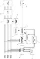
図1は第1の実施例における画像表示装置の機能ブロック図を示す。図1の画像表示装置は、液晶パネル部1、バックライトモジュール部2、輝度変化検出部3、フレームバッファ4、特徴量検出部5、特徴量保存部6、更新モード判定部7、バックライト輝度決定部8、輝度推測部9、補正係数計算部10を有する。図1の画像表示装置は更に、補正係
数乗算部11、Limit部12を有する。
FIG. 1 is a functional block diagram of the image display apparatus in the first embodiment. 1 includes a liquid
液晶パネル部1は、液晶ドライバ、及び入力画像信号を受けて液晶ドライバをコントロールするコントロール基板、液晶パネルで構成される。液晶パネル部1は、バックライトモジュール部2からの光を変調することで画面上に画像を表示する表示パネルである。本実施例では表示パネルとして液晶パネルを備えた、透過型の画像表示装置に本発明を適用した例を説明するが、本発明の適用対象は液晶表示装置に限らない。画像表示装置は、独立した光源を有する画像表示装置であればよい。例えば、画像表示装置は、反射型の液晶表示装置であってもよい。また、画像表示装置は、液晶素子の代わりにMEMS(Micro Electro Mechanical System)シャッターを用いたMEMSシャッター方式ディスプレイ
であってもよい。
The liquid
バックライトモジュール部2は、バックライト用の発光素子、発光素子の発光を制御する制御回路、発光素子からの光を拡散させるための光学ユニットで構成される。バックライトは複数の領域に分割され、各領域には一又は複数の発光素子が含まれ、各領域を単位として発光が制御される。発光制御の単位となる領域を本明細書では「光源」と呼ぶ。すなわち、バックライトは個別に発光輝度を制御可能な複数の光源からなり、各光源は一又は複数の発光素子の集合により構成される。バックライトの領域分割数は、横m個、縦n個(m、nは整数)とする。本実施例ではバックライトの領域分割数は、横8個×縦6個とする。バックライトモジュール部2は、バックライト輝度決定部8で決定した輝度を受信して、各光源の発光輝度が受信した輝度となるように各光源を駆動する。
The
輝度変化検出部3は、フレームバッファ4に保存された画像データを読み出して、現在のフレームの画像データと過去のフレーム(本実施例では現在より1フレーム前のフレーム)の画像データとを比較し、輝度が変化した画素を検出し、カウントする。輝度変化検出部3は、カウントした値を更新モード判定部7へ出力する。なお、現在のフレームの画像と比較する過去のフレームの画像は、現在より1フレーム前のフレームに限らず、現在より2フレーム以上前のフレームの画像であってもよい。
The luminance
フレームバッファ4は、1フレーム分の画像データを保存する。輝度変化検出部3で比較が終わった過去のフレームの画像データを消去し、比較が終わった現在のフレームの画像データを保存する。
The
特徴量検出部5は、画像をバックライトの各光源に対応するブロックに分割し、ブロック毎に特徴量を検出する。特徴量検出部5は、検出した特徴量を後段の特徴量保存部6、バックライト輝度決定部8へ送る。本実施例では、特徴量検出部5は、ブロック毎にRGBの画素値の最大値を検出する。
The feature
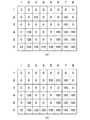
図11の入力画像の例で説明する。図11のカーソルがAの位置にある場合及びBの位置にある場合それぞれのブロック毎の最大画素値を図2(a)、図2(b)に示す。カーソルの画像を構成する画素の階調値を255とする。図2(a)の座標(3,2)、及び図2(b)の座標(5,2)、(6,2)の位置にカーソルが存在するので、上記の座標の最大画素値として255の値が検出される。 An example of the input image in FIG. 11 will be described. When the cursor in FIG. 11 is at the position A and at the position B, the maximum pixel value for each block is shown in FIGS. 2 (a) and 2 (b). The gradation value of the pixels constituting the cursor image is 255. Since the cursor exists at the position of the coordinates (3, 2) in FIG. 2A and the coordinates (5, 2), (6, 2) in FIG. 2B, the maximum pixel value of the above coordinates is 255. The value of is detected.
特徴量保存部6は、特徴量検出部5で検出した各ブロックの特徴量を保存する。保存するタイミングは、後述する更新モード判定部7の判定結果を受けたタイミングである。更新モード判定部7からは、更新モード0、更新モード1、更新モード2のいずれかの更新モードが設定される。
The feature
更新モード0では、特徴量保存部6は、全てのブロックについて、保存している特徴量
を、特徴量検出部5により検出された現在のフレームの特徴量で更新する。
In the
更新モード1では、特徴量保存部6は、保存している特徴量に対し、特徴量検出部5により検出された現在のフレームの特徴量が低下したブロックについてのみ、保存している特徴量を、特徴量検出部5により検出された現在のフレームの特徴量で更新する。具体的には、特徴量保存部6は、ブロック毎に保存している最大画素値を読み出して、現在のフレームについて特徴量検出部5により検出された最大画素値とブロック毎に比較する。現在のフレームの最大画素値の方が保存している最大画素値より小さいブロックについて、特徴量保存部6は、現在のフレームの最大画素値で、保存している最大画素値を更新する。一方、現在のフレームの最大画素値が保存している最大画素値以上のブロックについて、特徴量保存部6は、保存している最大画素値を更新しない。
In the
更新モード2では、特徴量保存部6は、全てのブロックについて、保存している特徴量を更新しない。
In the
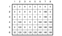
特徴量保存部6は、更新モード判定部7から更新モード0という判定結果を受信すると、以下のように特徴量の更新を行う。例えば、ブロック毎の最大値が図2(a)から図2(b)へ変化した場合について説明する。座標(3,2)のブロックの最大画素値は、図2(a)では255だが、図2(b)では0となることから、図2(a)から図2(b)に変化したとき、最大画素値が低くなっている。そのため、特徴量保存部6は、座標(3,2)のブロックについて保存している最大画素値を、図2(b)の最大画素値で更新する。一方、(5,2)のブロックの最大画素値は、0から255へ変化しており、大きくなっていることから、特徴量保存部6は、このブロックについて保存している最大画素値を更新しない。座標(6,2)のブロックも同様である。他のブロックは図2(a)と図2(b)とで最大画素値が同じなので、特徴量保存部6は、これらのブロックについて保存している最大画素値を更新しない。このようにして、過去のフレームで保存された特徴量が図2(a)、現在のフレームで検出された特徴量が図2(b)である場合に、図2(a)の特徴量を更新した結果を、図3に示す。
When the feature
特徴量保存部6は、更新モード判定部7から更新モード0という判定結果を受信すると、保存している全てのブロックの最大画素値を、現在のフレームについて特徴量検出部5により検出された最大画素値で更新する。
特徴量保存部6は、更新モード判定部7から更新モード2という判定結果を受信すると、保存している全てのブロックの最大画素値を更新しない。
特徴量保存部6は、保存している特徴量を、バックライト輝度決定部8の要求に応じて出力する。
When the feature
When the feature
The feature
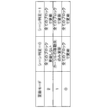
更新モード判定部7は、輝度変化検出部3の検出結果に応じて特徴量保存部6の特徴量の更新モードを決定する。具体的には、更新モード判定部7は、輝度変化した画素数が閾値以下の場合、更新モード1に設定する。すなわち、特徴量(最大画素値)が低下するブロックのみ特徴量を更新する更新モードに設定する。この閾値は、カーソル移動に伴って輝度変化する画素数に基づいて定められる。
The update
本実施例における輝度が変化した画素数と更新モードとの関係を図4に示す。本実施例では、入力画像の画素数は横1920画素×縦1080画素とする。カーソルの画像の画素数は200画素以下であるとする。カーソルが移動すると、移動元と移動先で輝度が変化する可能性がある。 FIG. 4 shows the relationship between the number of pixels whose luminance has changed and the update mode in this embodiment. In the present embodiment, the number of pixels of the input image is 1920 horizontal pixels × 1080 vertical pixels. It is assumed that the number of pixels of the cursor image is 200 pixels or less. When the cursor moves, the luminance may change between the movement source and the movement destination.
輝度が変化した画素が存在し、その数が200×2=400画素以下の場合、更新モード判定部7は、カーソルの移動があると判定し、更新モード1に設定する。この場合、特
徴量が大きくなったブロックについては保存されている特徴量が更新されず、特徴量が低くなったブロックのみ保存されている特徴量が更新される。これにより、カーソルの移動先のブロックで輝度が上昇することが抑制され、カーソルの移動元のブロックでは輝度が低下する。従って、ハロー効果が抑制され、且つハローがカーソル移動に伴って移動することによるフリッカの発生が抑制される。
When there are pixels whose luminance has changed and the number thereof is 200 × 2 = 400 pixels or less, the update
輝度が変化した画素が存在し、その数が400画素を超える場合、更新モード判定部7は、入力画像は静止画像であるが画像が変化したか、或いは入力画像は動画像であると判定し、更新モード0に設定する。この場合、全ブロックについて、保存されている特徴量が更新される。従って、全てのブロックの輝度が、現在のフレームの画像に応じた輝度となり、高いコントラストで画像表示が行われる。
輝度が変化した画素数が0の場合、更新モード判定部7は、前後フレームで画像の変化がないと判定し、更新モード2に設定し、保存されている特徴量が更新されないようにする。
更新モード判定部7は、以上のようにして決定した更新モードの情報を特徴量保存部6、及びバックライト輝度決定部8へ送る。
When there are pixels whose luminance has changed and the number exceeds 400 pixels, the update
When the number of pixels whose luminance has changed is 0, the update
The update
バックライト輝度決定部8は、特徴量検出部5で検出した特徴量、或いは特徴量保存部6で保存した特徴量から、光源毎のバックライトの輝度を決定する。特徴量検出部5で検出した特徴量、或いは特徴量保存部6で保存した特徴量のどちらを用いてバックライト輝度を決定するかは、更新モード判定部7で決定した更新モードに基づいて決定される。更新モード1、或いは更新モード2の場合、バックライト輝度決定部8は、特徴量保存部6で保存した特徴量からバックライト輝度を計算する。更新モード0の場合、バックライト輝度決定部8は、特徴量検出部5で検出した特徴量を用いて計算する。
The backlight
バックライト輝度決定部8は、各ブロックの特徴量(本実施例では最大画素値)と、ルックアップテーブルとして保存されているバックライト輝度と特徴量との対応関係の情報と、に基づき、各ブロックに対応する光源の発光輝度を決定する。ルックアップテーブルの一例を図5に示す。図5は横軸に入力としての最大画素値、縦軸に出力としてのバックライト輝度を示す。バックライト輝度が0とは、光源が点灯しない状態を示し、バックライト輝度が100とは、光源が明るさ最大で点灯する状態を示す。
Based on the feature amount (maximum pixel value in this embodiment) of each block and the information on the correspondence between the backlight luminance and the feature amount stored as a lookup table, the backlight
ブロック毎の特徴量(最大画素値)が図3である場合に、図5のルックアップテーブルを参照して決定される、光源毎の発光輝度を図6に示す。図6に示すように、図11の画像のようにカーソルが移動した場合、カーソルの移動元の(3,2)のブロックに対応する光源の輝度は0に決定される。またカーソルの移動先の(5,2)及び(6,2)のブロックに対応する光源の輝度も0に決定される。このことから、高輝度画像で構成される所定のオブジェクト(ここでは、ユーザ操作を補助する補助オブジェクトとしてのマウスカーソル)の存在によるハロー効果と、オブジェクトの移動に伴うフリッカ(ハローの移動)の両方が抑制できていることがわかる。 FIG. 6 shows the light emission luminance for each light source determined with reference to the lookup table of FIG. 5 when the feature amount (maximum pixel value) for each block is FIG. As shown in FIG. 6, when the cursor moves as in the image of FIG. 11, the luminance of the light source corresponding to the (3, 2) block from which the cursor is moved is determined to be zero. The luminance of the light source corresponding to the blocks (5, 2) and (6, 2) to which the cursor is moved is also determined to be zero. From this, both of the halo effect due to the presence of a predetermined object (here, a mouse cursor as an auxiliary object that assists the user operation) composed of a high-intensity image and flicker (movement of halo) accompanying the movement of the object It can be seen that is suppressed.
バックライト輝度決定部8は、以上のようにして決定した光源毎のバックライト輝度を輝度推測部9、及びバックライトモジュール部2へ送る。なお、本実施例ではルックアップテーブルを用いて輝度を決定したが、計算式を用いて決定してもよい。
The backlight
輝度推測部9は、バックライトモジュール部2の点灯によって液晶パネル部1に入射する光の輝度を推測する。本実施例では、輝度推測部9は、各ブロックの中心点における輝度を推測するものとする。輝度推測部9は、各ブロックに対応するバックライトの光源が点灯した場合の周辺の領域への漏れ光の強度に関する情報をメモリから読み出す。本実施例では、漏れ光の強度の情報は、各ブロックの中心点における減衰係数としてメモリに保
存されているものとする。輝度推測部9は、メモリから読み出した減衰係数と、バックライト輝度決定部8で決定した各光源のバックライト輝度と、を乗算する計算により、輝度の推測を行う。輝度推測部9は、推測した輝度を補正係数計算部10に送る。
The
補正係数計算部10は、輝度推測部9で計算した各ブロックの中心点の輝度の推測結果から、画像データを補正するための補正係数を求める。補正係数は、バックライトの輝度を下げたことによる表示輝度の低下を補償するために画素値を伸長する計算に用いる係数である。バックライトの輝度が高くなってしまい、表示輝度が目標の輝度より高くなるブロックでは、補正係数計算部10は、輝度を下げる補正が画素値に対し行われるよう補正係数を求める。あるブロックの中心点の推測輝度をLpn、補正係数で伸長又は調整した後の目標となる輝度をLt、当該中心点の補正係数をGpnとすると、補正係数Gpnは、下記式で求めることができる。
Gpn=Lt/Lpn
なお、目標輝度Ltは、画面のピーク輝度に基づき決定する。なお、輝度推測は離散的な中心点について行われているため、ブロックの中心点と中心点の間の画素に対応する補正係数は、周囲の中心点における推測輝度及び周囲の中心点との位置関係に基づく補間演算により求める。
The correction
Gpn = Lt / Lpn
The target brightness Lt is determined based on the peak brightness of the screen. Since luminance estimation is performed for discrete center points, the correction coefficient corresponding to the pixel between the center point of the block is the estimated luminance at the surrounding center point and the position of the surrounding center point. Obtained by interpolation based on the relationship.
補正係数乗算部11は、補正係数計算部10で決定した補正係数を対応する画素の画像データに乗算し、画像データを補正する。補正係数乗算部11は、補正した画像データをLimit部12へ送る。
The
Limit部12は、補正係数乗算部11で補正された画像データが液晶パネル部1の入力レンジを超えている場合に、入力レンジに収まるように画像データを修正する。
When the image data corrected by the correction
以上が実施例1の詳細である。以上の構成によって、発光輝度を決定する対象フレームの画像と過去のフレームの画像との差異が所定のオブジェクト(カーソル)の移動によるものである場合、過去のフレームより明るい画像の領域に対応する光源の発光輝度の変化が抑制される。画像の暗部領域において高輝度のオブジェクト画像(カーソル)が移動した場合においても、移動元のブロックも移動先のブロックもどちらもカーソルの高輝度画素値に反応して明るく点灯することを防止できる。すなわち、元の画像においてカーソルが存在しない状態でのバックライト輝度で各光源を発光させることができるので、コントラスト向上と、ハロー効果及びフリッカの抑制と、を好適に両立させることができる。 The above is the details of the first embodiment. With the above configuration, when the difference between the image of the target frame for determining the light emission luminance and the image of the past frame is due to the movement of the predetermined object (cursor), the light source corresponding to the image area brighter than the past frame The change in the emission luminance is suppressed. Even when a high-brightness object image (cursor) moves in the dark area of the image, both the source block and the destination block can be prevented from being lit brightly in response to the high-brightness pixel value of the cursor. That is, since each light source can emit light with the backlight brightness in the state where the cursor does not exist in the original image, it is possible to preferably achieve both improvement in contrast and suppression of the halo effect and flicker.
本実施例では、カーソルの移動先のブロックの特徴量を、カーソルが存在しないときに算出された特徴量のままにして更新しないことで、カーソルを構成する高輝度画素に起因してハローとフリッカが生じることを抑制する方法を説明した。しかしながら、カーソルの移動先ブロックが周囲も含めて画像の暗部領域である場合、カーソルの表示輝度が暗くなりカーソルの視認性が低下する可能性がある。そこで、特徴量保存部6でカーソルの移動先のブロックの特徴量を、過去のフレームと現在のフレームのブロックの特徴量の平均値を求め、その平均値でカーソルの移動先のブロックの特徴量を更新してもよい。こうすることで妨害感が気にならない程度にカーソルの視認性が向上する。本実施例において、発光輝度を決定する対象フレームにおいて過去のフレームより明るい画像の領域に対応する光源の発光輝度を、過去のフレームの当該領域に対応する光源の発光輝度から変化させないようにしても良い。或いは、対象フレームにおいて当該明るい画像の領域に対応する光源の発光輝度を、当該明るい画像に応じた発光輝度よりも低くすることにより、過去のフレームの当該領域に対応する光源の発光輝度からの変化を抑制するようにしても良い。
In this embodiment, the feature amount of the block to which the cursor is moved remains the same as the feature amount calculated when the cursor does not exist, and is not updated, so that halo and flicker are caused by the high-intensity pixels constituting the cursor. A method of suppressing the occurrence of the above has been described. However, when the destination block of the cursor is the dark area of the image including the surrounding area, the display brightness of the cursor becomes dark and the visibility of the cursor may be lowered. Therefore, the feature
(実施例2)
実施例1では、現在のフレームの特徴量と保存されている過去のフレームの特徴量とから現在のフレームにおいてカーソルが存在しない場合の特徴量を求め、その特徴量に基づき現在のフレームの表示に適用するバックライト輝度を決定した。実施例2では、現在のフレームの特徴量から決定したバックライト輝度と過去のバックライト輝度とから、現在のフレームにおいてカーソルが存在しない場合のバックライト輝度を求める。これにより、実施例1と同様に、入力画像に応じたローカルディミングによりコントラスト向上を行う画像表示装置において、画像の暗部領域を高輝度のカーソルが移動した場合のハロー効果とフリッカの両方を抑制することができる。
(Example 2)
In the first embodiment, the feature amount when the cursor is not present in the current frame is obtained from the feature amount of the current frame and the saved feature amount of the past frame, and the current frame is displayed based on the feature amount. The backlight brightness to be applied was determined. In the second embodiment, the backlight luminance when the cursor is not present in the current frame is obtained from the backlight luminance determined from the feature amount of the current frame and the past backlight luminance. As a result, in the same manner as in the first embodiment, in the image display device that improves the contrast by local dimming according to the input image, both the halo effect and flicker are suppressed when the high-brightness cursor moves in the dark area of the image. be able to.
図7は第2の実施例における画像表示装置の機能ブロック図を示す。図7の画像表示装置は、液晶パネル部1、バックライトモジュール部2、輝度変化検出部3、フレームバッファ4、特徴量検出部5、更新モード判定部7、バックライト輝度仮決定部101、バックライト輝度決定部102、バックライト輝度保存部103を有する。図7の画像表示装置は更に、輝度推測部9、補正係数計算部10、補正係数乗算部11、Limit部12を有する。
FIG. 7 shows a functional block diagram of the image display apparatus in the second embodiment. 7 includes a liquid
液晶パネル部1、バックライトモジュール部2、輝度変化検出部3、フレームバッファ4、特徴量検出部5、更新モード判定部7、輝度推測部9、補正係数計算部10、補正係数乗算部11、Limit部12は、実施例1と同様なので説明を省略する。
Liquid
バックライト輝度仮決定部101は、特徴量検出部5で検出した特徴量から、光源毎のバックライト輝度を仮決定する。本実施例では、実施例1と同様に、各ブロックの最大画素値から各ブロックに対応する光源のバックライト輝度を仮決定する。決定方法は実施例1のバックライト輝度決定部8と同じなので説明を省略する。
The backlight luminance
バックライト輝度決定部102は、バックライト輝度仮決定部101で仮決定したバックライト輝度と、バックライト輝度保存部103で保存されたバックライト輝度と、に基づき、バックライト輝度を決定する。具体的には、バックライト輝度決定部102は、更新モード判定部7の更新モードの判定結果に基づき、光源毎のバックライト輝度を決定する。
The backlight
更新モード0の場合、バックライト輝度決定部102は、全ての光源について、バックライト輝度仮決定部101で仮決定したバックライト輝度を、現在のフレームの表示に適用するバックライト輝度として決定する。また、バックライト輝度決定部102は、バックライト輝度保存部103に保存されている全ての光源のバックライト輝度を、バックライト輝度仮決定部101で仮決定したバックライト輝度で置き換える(更新する)。
In the
更新モード1の場合、カーソルが移動したシーンであると判断できる。バックライト輝度決定部102は、バックライト輝度仮決定部101で仮決定した輝度と、バックライト輝度保存部103に保存されている過去の輝度と、を比べ、輝度が低い方を選択して現在のフレームの表示に適用するバックライト輝度として決定する。また、バックライト輝度決定部102は、現在のフレームの表示に適用するバックライト輝度としてバックライト輝度仮決定部101で仮決定した輝度が選択された光源のバックライト輝度を、当該選択したバックライト輝度で更新する。
In the case of
図8(a)、図8(b)を用いて説明する。図8(a)にバックライト輝度仮決定部101で仮決定したバックライト輝度を、図8(b)にバックライト輝度保存部103で保存されたバックライト輝度の例を示す。図8(a)、図8(b)の各ブロック内の数値がバックライト輝度を示す。また格子の外側の横1〜8、縦1〜6の数値はそれぞれ水平/
垂直方向の座標を示す。
This will be described with reference to FIGS. 8A and 8B. FIG. 8A shows an example of the backlight luminance temporarily determined by the backlight luminance
Indicates the vertical coordinate.
座標(3,2)の光源の輝度は図8(a)では0、図8(b)では100である。そのため、バックライト輝度決定部102は、低い方の輝度、すなわち図8(a)に示す、バックライト輝度仮決定部101で仮決定したバックライト輝度を現在のフレームの表示に適用するバックライト輝度として選択する。更に、バックライト輝度保存部103に対して、保存している座標(3,2)の光源の輝度を仮決定したバックライト輝度で更新するように指示を送る。
The luminance of the light source at the coordinates (3, 2) is 0 in FIG. 8A and 100 in FIG. Therefore, the backlight
また座標(5,2)、及び(6,2)の光源の輝度は、図8(a)では100、図8(b)では0である。そのため、バックライト輝度決定部102は、低い方の輝度、すなわち図8(b)に示す、バックライト輝度保存部103で保存されたバックライト輝度を現在のフレームの表示に適用するバックライト輝度として選択する。
The luminance of the light source at coordinates (5, 2) and (6, 2) is 100 in FIG. 8A and 0 in FIG. 8B. Therefore, the backlight
他のブロックの光源は、バックライト輝度仮決定部101で仮決定したバックライト輝度とバックライト輝度保存部103で保存されたバックライト輝度とで変化がないことから、現在のフレームの表示に適用するバックライト輝度としてどちらの値を用いてもよい。本実施例では、このような場合にはバックライト輝度仮決定部101で決定した値を現在のフレームの表示に適用するバックライト輝度として用いる。
The light sources of other blocks are applied to the display of the current frame because there is no change between the backlight luminance temporarily determined by the backlight luminance
このようにして決定した現在のフレームの表示に適用するバックライト輝度は、実施例1と同様に、図6で示すようになる。 The backlight luminance applied to the display of the current frame determined in this way is as shown in FIG.
更新モード2の場合は、画像に変化がないので、現在のフレームの表示に適用するバックライト輝度として、バックライト輝度仮決定部101で仮決定したバックライト輝度とバックライト輝度保存部103で保存されたバックライト輝度とのどちらを用いてもよい。本実施例ではバックライト輝度保存部103で保存した輝度を用いる。
In the
バックライト輝度決定部102は、このようにして決定した現在のフレームの表示に適用するバックライト輝度の情報を、後段の輝度推測部9、及びバックライトモジュール部2へ出力する。
The backlight
以上が実施例2の詳細である。以上の構成によって、実施例1と同様に、画像の暗部領域において高輝度のオブジェクト画像(カーソル)が移動した場合においても、移動元のブロックも移動先のブロックもどちらもカーソルの高輝度画素値につられて明るく点灯することがなくなる。すなわち、元の画像においてカーソルが存在しなければ実現されることになるバックライト輝度で各光源を発光させることができるので、ローカルディミングによるコントラスト向上と、ハロー効果及びフリッカの抑制と、を両立させることができる。 The above is the details of the second embodiment. With the above configuration, as in the first embodiment, even when a high-brightness object image (cursor) moves in the dark area of the image, both the source block and the destination block have high-brightness pixel values. Will not light up brightly. That is, since each light source can emit light with a backlight luminance that is realized if the cursor is not present in the original image, both the improvement of contrast by local dimming and the suppression of the halo effect and flicker are achieved. be able to.
(実施例3)
実施例1、2では、前後フレームで輝度が変化した画素数をカウントし、そのカウント値と閾値を比較することでカーソルが移動したシーンを検出した。実施例3では、カーソルをオブジェクトとして直接検出することで、カーソルが移動したシーンを検出する。そして現在のフレームの特徴量と保存されている過去のフレームの特徴量とから、現在のフレームにおいてカーソルが存在しない場合の特徴量を求め、その特徴量に基づき現在のフレームの表示に適用するバックライト輝度を決定する。これにより、実施例1、2と同様に、入力画像に応じたローカルディミングによりコントラスト向上を行う画像表示装置において、画像の暗部領域を高輝度のカーソルが移動した場合のハロー効果とフリッカの両方を抑制することができる。また実施例1,2に比べ、カーソルを直接認識することから
、カーソルの移動のシーンの誤判定が少なくなる。
Example 3
In the first and second embodiments, the number of pixels whose luminance has changed in the preceding and following frames is counted, and the scene where the cursor has moved is detected by comparing the count value with a threshold value. In the third embodiment, a scene in which the cursor has moved is detected by directly detecting the cursor as an object. Then, from the feature amount of the current frame and the saved feature amount of the past frame, the feature amount when the cursor does not exist in the current frame is obtained, and the back applied to the display of the current frame based on the feature amount Determine the light brightness. As a result, in the same manner as in the first and second embodiments, in the image display device that improves the contrast by local dimming according to the input image, both the halo effect and flicker when the high-brightness cursor moves in the dark area of the image. Can be suppressed. Compared with the first and second embodiments, since the cursor is directly recognized, erroneous determination of the scene of the cursor movement is reduced.
図9は第3の実施例における画像表示装置の機能ブロック図を示す。図9の画像表示装置は、液晶パネル部1、バックライトモジュール部2、カーソル検出部201、パターン記憶部202、カーソル移動検出部203、更新モード判定部204、シーン判定部205、特徴量保存部206、特徴量検出部5を有する。図9の画像表示装置は更に、バックライト輝度決定部207、輝度推測部9、補正係数計算部10、補正係数乗算部11、Limit部12を有する。
液晶パネル部1、バックライトモジュール部2、特徴量検出部5、輝度推測部9、補正係数計算部10、補正係数乗算部11、Limit部12は、実施例1と同様なので説明を省略する。
FIG. 9 shows a functional block diagram of the image display apparatus in the third embodiment. 9 includes a liquid
Since the liquid
カーソル検出部201は、画像データからカーソルを検出する。検出方法は、カーソルとしてとりうる形状を記憶し、画像データの中に記憶したパターンと合致する形状のオブジェクトが存在するかを調べて検出する。カーソル形状のパターンの情報はパターン記憶部202に保存されており、カーソル検出部201は、必要なタイミングでパターン記憶部202からパターンの情報を読み出す。カーソル検出部201は、カーソルを検出すると、検出したカーソルの中心画素と、カーソルが所属するブロックの座標も求める。カーソル検出部201は、こうして求めた結果のうち、カーソルの中心画素の位置の情報をカーソル移動検出部203へ出力する。カーソル検出部201は、カーソルが所属するブロックの座標の情報を特徴量保存部206へ出力する。
The
カーソル移動検出部203は、カーソル検出部201で検出したカーソルの中心画素の位置の情報を保存し、カーソルの中心画素の位置が変化したことを検出する。具体的には、カーソル移動検出部203は、保存したカーソルの中心画素の位置と、カーソル検出部201から新たに受信したカーソルの中心画素の位置と、を比べ、変化があるか調べる。
The cursor
カーソルの中心画素の位置に変化があった場合、カーソル移動検出部203は、更新モード判定部204へ、カーソルが移動したことを示す値「1」を通知する。
カーソルの中心画素の位置に変化はないが、カーソルが検出されている場合、カーソル移動検出部203は、更新モード判定部204へ、カーソルは存在するがカーソルは移動していないことを示す値「2」を通知する。
カーソルが検出されていない場合、カーソル移動検出部203は、更新モード判定部204へ、カーソルが存在しないことを示す値「0」を通知する。
When there is a change in the position of the center pixel of the cursor, the cursor
If there is no change in the position of the center pixel of the cursor, but the cursor is detected, the cursor
When the cursor is not detected, the cursor
更新モード判定部204は、特徴量保存部206と、バックライト輝度決定部207に更新モードの情報を通知する。カーソル移動検出部203から、カーソルの移動があったことを示す値「1」が通知されると、更新モード判定部204は、更新モード1を設定する。カーソルは検出されているが、カーソルの移動検出がないことを示す値「2」が通知されると、更新モード判定部204は、更新モード2を設定する。カーソルが検出されていないことを示す値「0」が通知されると、更新モード判定部204は、更新モード0と設定する。
The update
シーン判定部205は、特徴量の前後フレームの変化から、静止画像/動画像判定を行う。静止画像の場合でも、画像が変化した場合は動画像と判定される。シーン判定部205は、特徴量検出部5で検出された特徴量、及び特徴量保存部206で保存された特徴量をそれぞれ読み出して、特徴量が変化したブロックをカウントする。本実施例では、シーン判定部205は、特徴量の最大値が変化したブロックをカウントする。なお、本実施例では特徴量の最大値に基づいてシーン変化を判定するが、特徴量の平均値をシーン変化の判定に用いてもよい。或いは特徴量の最大値、及び特徴量の平均値の両方に基づいてシー
ン変化を判定してもよい。特徴量の最大値が変化したブロックの数が予め設定された閾値以上の場合、シーン判定部205は、入力画像が動画像であると判定し、動画像であることを示す値「1」を特徴量保存部206へ出力する。それ以外の場合、シーン判定部205は、入力画像が静止画像であることを示す値「0」を特徴量保存部206へ出力する。
The
特徴量保存部206は、特徴量検出部5で検出した特徴量を保存する。特徴量保存部206は、更新モード判定部204、及びシーン判定部205の結果を受けて、データを更新するブロックを選択する。更新モード判定部204の更新モードと、シーン判定部の判定結果と、更新するブロックの選択方法と、の関係を図10に示す。シーン判定で「1」の場合、すなわち動画像の場合、更新モード判定部204の更新モードの結果に関わらず、特徴量保存部206は、保存している全てのブロックの特徴量を特徴量検出部5で検出された現在のフレームの特徴量で更新する。一方、シーン判定部205の判定結果が0の場合は、更新モードによって処理が異なる。
The feature
更新モード0の場合、カーソルが存在しない。そのため、特徴量保存部206は、全てのブロックの特徴量を、特徴量検出部5で検出された現在のフレームの特徴量で更新する。
In
更新モード1の場合、カーソルが移動したシーンである。静止画像で且つカーソルの移動が伴う場合、カーソルの移動によってハロー効果や、フリッカが発生する可能性がある。そのため、カーソルの移動先のブロックにおけるバックライト輝度の上昇を抑制するため、特徴量保存部206は、カーソル移動先のブロックについては、特徴量検出部5で検出した特徴量で更新しない。特徴量保存部206は、カーソルの移動先のブロックの座標を、カーソル検出部201から受信する。一方、特徴量保存部206は、カーソルの移動元のブロック、及び他のブロックについては、特徴量検出部5で検出した特徴量で更新する。
In the case of
更新モード2の場合、静止画像で且つカーソルの移動もないことから、特徴量保存部206は、全てのブロックについて、特徴量の更新を行わない。
In the
バックライト輝度決定部207は、特徴量保存部206で保存された特徴量に応じて、各ブロックに対応する光源のバックライト輝度を決定する。決定方法は実施例1と同様なので説明を省略する。
The backlight
以上が実施例3の詳細である。以上の構成によって、実施例1、2と同様に、画像の暗部領域において高輝度のオブジェクト画像(カーソル)が移動した場合においても、コントラスト向上と、ハロー効果及びフリッカの抑制と、を両立させることができる。また実施例1,2に比べ、カーソルを直接認識することから、カーソルの移動のシーンの誤判定が少なくなる。 The above is the details of the third embodiment. With the above configuration, as in the first and second embodiments, even when a high-brightness object image (cursor) moves in the dark area of the image, both improvement in contrast and suppression of the halo effect and flicker are achieved. Can do. Compared with the first and second embodiments, since the cursor is directly recognized, erroneous determination of the scene of the cursor movement is reduced.
(実施例4)
これまでの実施例では、マウスカーソルの移動を検出し、過去の統計値や過去のバックライト輝度に基づきバックライト輝度を制御することで、マウスカーソルの移動に起因するバックライトの輝度の変化を抑制、或いは変化しないようにした。これにより、マウスカーソルの移動によるハローとフリッカを抑制した。
Example 4
In the embodiments so far, the movement of the mouse cursor is detected, and the backlight brightness is controlled based on the past statistical value and the past backlight brightness, so that the change in the backlight brightness caused by the movement of the mouse cursor is detected. Suppressed or changed. As a result, halo and flicker caused by movement of the mouse cursor were suppressed.
実施例4では、マウスカーソルが移動したシーンを検出し、マウスカーソルの移動先のブロックを特定する。マウスカーソルの移動先のブロックについては、特徴量の変化に応じたバックライト輝度の変化の速度(変化率、フレームあたりの変化量、単位時間当たりの変化量)を、通常のブロックよりも小さくする。通常のブロックとは、マウスカーソル
の移動先のブロック以外のブロックである。これにより、マウスカーソルの移動先のブロックにおいて、明るい画素から構成されるマウスカーソルが現れることによってバックライトが急に明るくなることが抑制される。またマウスカーソルの移動先のブロックでマウスカーソルが止まった場合においても、当該移動先のブロックのバックライトの輝度はゆっくり上昇するので、フリッカとして認識されることを抑制できる。
In the fourth embodiment, a scene where the mouse cursor has moved is detected, and a block to which the mouse cursor is moved is specified. For the block to which the mouse cursor is moved, the speed of change of the backlight brightness (change rate, change amount per frame, change amount per unit time) according to the change of the feature amount is made smaller than that of the normal block. . A normal block is a block other than the block to which the mouse cursor is moved. Thereby, in the block to which the mouse cursor is moved, it is suppressed that the backlight suddenly becomes bright due to the appearance of the mouse cursor composed of bright pixels. Further, even when the mouse cursor stops at the movement destination block of the mouse cursor, the luminance of the backlight of the movement destination block increases slowly, so that recognition as flicker can be suppressed.
図12に実施例4の機能ブロック図を示す。図12の画像表示装置は、液晶パネル部1、バックライトモジュール部2、特徴量検出部301、特徴量保存部206、シーン判定部302、カーソル移動ブロック検出部303、バックライト輝度仮決定部304、平滑化処理部305を有する。図12の画像表示装置は更に、バックライト輝度保存部306、輝度推測部9、補正係数計算部10、補正係数乗算部11、Limit部12を有する。
FIG. 12 shows a functional block diagram of the fourth embodiment. 12 includes a liquid
特徴量検出部301は、実施例1と同様にバックライトの各光源に対応するブロック毎の画素値の最大値や平均値を検出するとともに、ブロック毎に明るい画素の数(明画素数という)をカウントし、特徴量として取得する。ここで、明るい画素とは、画素値(階調値)が所定の閾値以上である画素とする。閾値としては、例えば、マウスカーソルの画像を構成する画素の画素値として典型的な値を設定することができる。
The feature
シーン判定部302は、マウスカーソルが移動したシーンを判定する。シーン判定部302は、例えば、ブロック内の画素値の最大値がフレーム間で増大したブロック数が閾値以下、かつ、ブロック内の画素値の最大値がフレーム間で減少したブロック数が閾値以下の場合に、カーソルが移動したシーンと判定する。或いは、シーン判定部302は、各ブロック内の画素値の平均値のフレーム間の差分の絶対値の全ブロックについての和が閾値以下である場合に、カーソルが移動したシーンと判定してもよい。或いは、シーン判定部302は、上記の両方の条件が満たされた場合に、カーソルが移動したシーンと判定してもよい。或いは、シーン判定部302は、実施例1〜3に記載した方法を用いてカーソルの移動を検出し、その検出結果を用いてカーソルが移動したシーンを検出してもよい。シーン判定部302は、シーン判定結果をカーソル移動ブロック検出部303に出力する。
The
カーソル移動ブロック検出部303は、シーン判定部302でカーソルが移動したシーンが検出された場合に、カーソルの移動先のブロックを検出する。カーソル移動ブロック検出部303は、カーソルの移動先であるか否かを判定する対象ブロックの明画素数を取得する。そして、対象ブロックの明画素数が1以上で且つ閾値以下であり、且つ、対象ブロックの画素値の平均値と周囲のブロックの画素値の平均値との差分が閾値以下である場合に、カーソル移動ブロック検出部303は当該対象ブロックをカーソルの移動先と判定する。カーソル移動ブロック検出部303は、カーソルの移動先のブロックとして検出したブロックの情報を平滑化処理部305へ出力する。
The cursor movement
バックライト輝度仮決定部304は、実施例1〜3と同様に、特徴量検出部301で検出した特徴量に基づき、光源毎のバックライト輝度を仮決定する。バックライト輝度仮決定部304は、仮決定した光源毎のバックライト輝度を平滑化処理部305へ送る。
Similar to the first to third embodiments, the backlight luminance
平滑化処理部305は、バックライト輝度仮決定部304で決定されたバックライト輝度と、バックライト輝度保存部306に保存されている1フレーム前のバックライト輝度と、に基づき、光源毎のバックライト輝度を決定する。すなわち、平滑化処理部305は、過去のフレームから発光輝度を決定する対象フレームへの画像の明るさの変化量に応じて光源の発光輝度の変化量を制御するものであり、画像の明るさの変化量に対する発光輝度の変化量の比率は所定の係数で表される。平滑化処理部305は、バックライト輝度仮決定部304で仮決定されたバックライト輝度が前フレームの表示に適用されたバックラ
イト輝度よりも高い場合、その差分を計算し、当該差分に所定の係数を乗じた値を、前フレームのバックライト輝度に加算する。この係数は、現フレームと前フレームとの画像の明るさの変化量に対する光源の発光輝度の変化量の比率を表す。
例えば、前フレームのバックライト輝度をL(-1)、現在のフレームの仮決定されたバッ
クライト輝度をpreL(0)とすると、その差分ΔLは次のようになる。
ΔL=preL(0)−L(-1)
平滑化処理部305は、カーソル移動ブロック検出部303によりカーソル移動先ブロックとして検出されていないブロックについて、現在のフレームのバックライト輝度L(0)を次のように求める。
L(0)=L(-1)+ΔL×α/100
ここで、係数はα(%)である。一方、平滑化処理部305は、カーソル移動ブロック検出部303によりカーソル移動先ブロックとして検出されたブロックについては、係数をβ(%)とする。ここでα>>βである。平滑化処理部305は、カーソル移動先ブロックのバックライト輝度を、次のように求める。
L(0)=L(-1)+ΔL×β/100
Based on the backlight luminance determined by the backlight luminance
For example, assuming that the backlight luminance of the previous frame is L (−1) and the backlight luminance temporarily determined for the current frame is preL (0), the difference ΔL is as follows.
ΔL = preL (0) −L (-1)
The smoothing
L (0) = L (-1) + ΔL × α / 100
Here, the coefficient is α (%). On the other hand, the smoothing
L (0) = L (-1) + ΔL × β / 100
すなわち、カーソル移動先ブロックではない通常のブロックでは係数αに基づき現フレームのバックライト輝度が決定されるが、カーソル移動先ブロックでは係数βに基づき現フレームのバックライト輝度が決定される。カーソル移動先ブロックでは、カーソルが移動してきたことによりブロック内の明るさを示す特徴量が増大し、特徴量に基づき仮決定されるバックライト輝度も増大するが、α>>βであるため、最終的に決定されるバックライト輝度では増大が抑えられる。そのため、カーソルに起因してバックライト輝度が増加することが抑制されるため、フリッカやハローを抑制することができる。
なお、カーソル移動先ブロックにおいてバックライト輝度の変化を十分に抑えるため、βはαの1/100以下の値にしてもよい。
That is, in the normal block that is not the cursor movement destination block, the backlight luminance of the current frame is determined based on the coefficient α, whereas in the cursor movement destination block, the backlight luminance of the current frame is determined based on the coefficient β. In the cursor movement destination block, the feature amount indicating the brightness in the block increases due to the movement of the cursor, and the backlight luminance temporarily determined based on the feature amount also increases, but α >> β. An increase in the finally determined backlight luminance is suppressed. Therefore, an increase in backlight luminance due to the cursor is suppressed, and flicker and halo can be suppressed.
Note that β may be set to 1/100 or less of α in order to sufficiently suppress a change in backlight luminance in the cursor movement destination block.
1 液晶パネル部、2 バックライトモジュール部、3 輝度変化検出部、5 特徴量検出部、7 更新モード判定部、8 バックライト輝度決定部
DESCRIPTION OF
Claims (20)
前記発光手段からの光を変調することで画面上に画像を表示する表示手段と、
前記複数の光源のそれぞれに対応する画面上の領域の画像に応じて、各光源の発光輝度を制御する制御手段と、
を備え、
前記制御手段は、発光輝度を決定する対象フレームの画像と、前記対象フレームより過去のフレームの画像との差異が、所定のオブジェクトの移動によるものである場合、対象フレームにおいて過去のフレームより明るい画像の領域に対応する光源の発光輝度の過去のフレームの当該領域に対応する光源の発光輝度からの変化を抑制することを特徴とする画像表示装置。 A light emitting means having a plurality of light sources capable of individually controlling the light emission brightness;
Display means for displaying an image on a screen by modulating light from the light emitting means;
Control means for controlling the light emission luminance of each light source according to the image of the area on the screen corresponding to each of the plurality of light sources;
With
When the difference between the image of the target frame for determining the light emission luminance and the image of the past frame from the target frame is due to the movement of the predetermined object, the control means is an image brighter than the past frame in the target frame. An image display device that suppresses a change in the light emission luminance of the light source corresponding to the region from the light emission luminance of the light source corresponding to the region in the past frame.
前記制御手段は、対象フレームの画像と過去のフレームの画像との差異が、所定のオブジェクトの移動によるものである場合、対象フレームの各領域の画像の明るさと、前記記憶手段に記憶されている過去のフレームの各領域の画像の明るさとを比較し、比較の結果、対象フレームにおいて過去のフレームより明るい画像の領域に対応する光源の発光輝度を、前記記憶手段に記憶されている過去のフレームの当該領域の画像の明るさに応じて決定する請求項1〜3のいずれか1項に記載の画像表示装置。 Storage means for storing information on the brightness of the image of the area corresponding to each light source used by the control means to determine the light emission luminance of each light source;
When the difference between the image of the target frame and the image of the past frame is due to the movement of a predetermined object, the control means stores the brightness of the image of each area of the target frame and the storage means. The brightness of the light source corresponding to the region of the image brighter than the past frame in the target frame is compared with the brightness of the image of each region of the past frame, and the past frame stored in the storage means The image display device according to claim 1, wherein the image display device is determined according to the brightness of the image in the region.
前記制御手段は、対象フレームの画像と過去のフレームの画像との差異が、所定のオブジェクトの移動によるものである場合、対象フレームの各領域の画像の明るさに応じて求めた各領域に対応する光源の発光輝度と、前記記憶手段に記憶されている過去のフレームの画像の表示に適用された各光源の発光輝度とを比較し、対象フレームにおいて過去のフレームより発光輝度が高い光源については、前記記憶手段に記憶されている過去のフレームの発光輝度を適用する請求項1〜3のいずれか1項に記載の画像表示装置。 Further comprising storage means for storing information on the emission luminance of each light source;
When the difference between the image of the target frame and the image of the past frame is due to the movement of a predetermined object, the control unit corresponds to each area obtained according to the brightness of the image of each area of the target frame. The light emission luminance of the light source to be compared with the light emission luminance of each light source applied to display the image of the past frame stored in the storage means, and for the light source having a light emission luminance higher than the past frame in the target frame The image display device according to claim 1, wherein the light emission luminance of a past frame stored in the storage unit is applied.
を適用する請求項7に記載の画像表示装置。 The said control means applies the light emission luminance of the past frame memorize | stored in the said memory | storage means about the light source from which the light emission luminance has not changed from the past frame in the object frame as a result of the comparison. Image display device.
応じて、対応する光源の発光輝度の変化量を制御するものであり、対象フレームにおける前記オブジェクトの移動先の領域に対応する光源について、それ以外の領域に対応する光源よりも、画像の明るさの変化量に対する発光輝度の変化量の比率を小さくする請求項17に記載の画像表示装置。 The control means controls the amount of change in emission luminance of the corresponding light source in accordance with the amount of change in brightness of the image area from the past frame to the target frame, and the movement destination of the object in the target frame The image display device according to claim 17, wherein the ratio of the amount of change in light emission luminance to the amount of change in brightness of the image is made smaller for light sources corresponding to the region than for light sources corresponding to other regions.
前記発光手段からの光を変調することで画面上に画像を表示する表示手段と、
を備えた画像表示装置の制御方法であって、
前記複数の光源のそれぞれに対応する画面上の領域の画像に応じて、各光源の発光輝度を制御する制御工程を有し、
前記制御工程では、発光輝度を決定する対象フレームの画像と、前記対象フレームより過去のフレームの画像との差異が、所定のオブジェクトの移動によるものである場合、対象フレームにおいて過去のフレームより明るい画像の領域に対応する光源の発光輝度の過去のフレームの当該領域に対応する光源の発光輝度からの変化を抑制することを特徴とする画像表示装置の制御方法。 A light emitting means having a plurality of light sources capable of individually controlling the light emission brightness;
Display means for displaying an image on a screen by modulating light from the light emitting means;
A method for controlling an image display device comprising:
A control step of controlling the light emission luminance of each light source according to the image of the area on the screen corresponding to each of the plurality of light sources;
In the control step, when the difference between the image of the target frame for determining the emission luminance and the image of the frame past the target frame is due to the movement of the predetermined object, the image brighter than the past frame in the target frame A method for controlling an image display device, comprising: suppressing a change in emission luminance of a light source corresponding to the region from a light emission luminance of a light source corresponding to the region in a past frame.
Priority Applications (2)
| Application Number | Priority Date | Filing Date | Title |
|---|---|---|---|
| JP2014107371A JP2015018219A (en) | 2013-06-14 | 2014-05-23 | Image display device and method for controlling the same |
| US14/303,971 US9773459B2 (en) | 2013-06-14 | 2014-06-13 | Image display apparatus that has a light emitting unit and method of controlling same |
Applications Claiming Priority (3)
| Application Number | Priority Date | Filing Date | Title |
|---|---|---|---|
| JP2013125312 | 2013-06-14 | ||
| JP2013125312 | 2013-06-14 | ||
| JP2014107371A JP2015018219A (en) | 2013-06-14 | 2014-05-23 | Image display device and method for controlling the same |
Related Child Applications (1)
| Application Number | Title | Priority Date | Filing Date |
|---|---|---|---|
| JP2019008881A Division JP6818781B2 (en) | 2013-06-14 | 2019-01-23 | Display device and its control method |
Publications (2)
| Publication Number | Publication Date |
|---|---|
| JP2015018219A true JP2015018219A (en) | 2015-01-29 |
| JP2015018219A5 JP2015018219A5 (en) | 2017-07-06 |
Family
ID=52018857
Family Applications (1)
| Application Number | Title | Priority Date | Filing Date |
|---|---|---|---|
| JP2014107371A Pending JP2015018219A (en) | 2013-06-14 | 2014-05-23 | Image display device and method for controlling the same |
Country Status (2)
| Country | Link |
|---|---|
| US (1) | US9773459B2 (en) |
| JP (1) | JP2015018219A (en) |
Cited By (4)
| Publication number | Priority date | Publication date | Assignee | Title |
|---|---|---|---|---|
| JP2016167057A (en) * | 2015-03-03 | 2016-09-15 | 株式会社半導体エネルギー研究所 | Information processor driving method, program, and information processor |
| JP2018031955A (en) * | 2016-08-26 | 2018-03-01 | キヤノン株式会社 | Display device |
| CN110992903A (en) * | 2019-12-25 | 2020-04-10 | 深圳创维-Rgb电子有限公司 | Display screen backlight brightness adjusting method and device, computer equipment and medium |
| JP2021131428A (en) * | 2020-02-18 | 2021-09-09 | 株式会社ジャパンディスプレイ | Display device |
Families Citing this family (8)
| Publication number | Priority date | Publication date | Assignee | Title |
|---|---|---|---|---|
| US9883137B2 (en) * | 2015-11-03 | 2018-01-30 | Qualcomm Incorporated | Updating regions for display based on video decoding mode |
| CN106023905B (en) * | 2016-05-27 | 2019-05-10 | 京东方科技集团股份有限公司 | The method of control display equipment, the control device for showing equipment and display equipment |
| TWI608463B (en) * | 2017-04-19 | 2017-12-11 | 中原大學 | Auto-selection type system for controlling backlight module and method for the same |
| CN108419028B (en) * | 2018-03-20 | 2020-07-17 | Oppo广东移动通信有限公司 | Image processing method, image processing device, computer-readable storage medium and electronic equipment |
| US11468854B2 (en) * | 2018-09-18 | 2022-10-11 | Apple Inc. | Adaptive headroom adjustment systems and methods for electronic device displays |
| US10504453B1 (en) * | 2019-04-18 | 2019-12-10 | Apple Inc. | Displays with adjustable direct-lit backlight units |
| CN112863451B (en) * | 2021-01-18 | 2022-04-19 | 海信视像科技股份有限公司 | Display apparatus and backlight control method |
| US11508322B1 (en) * | 2021-06-03 | 2022-11-22 | Dell Products L.P. | Method and system for dynamically setting backlight dimming algorithm for displays |
Citations (2)
| Publication number | Priority date | Publication date | Assignee | Title |
|---|---|---|---|---|
| JP2012226230A (en) * | 2011-04-22 | 2012-11-15 | Hitachi Consumer Electronics Co Ltd | Backlight device and video display device |
| JP6071469B2 (en) * | 2011-12-19 | 2017-02-01 | キヤノン株式会社 | Image display apparatus and control method thereof |
Family Cites Families (16)
| Publication number | Priority date | Publication date | Assignee | Title |
|---|---|---|---|---|
| JP2765674B2 (en) * | 1993-12-16 | 1998-06-18 | インターナショナル・ビジネス・マシーンズ・コーポレイション | Data supply device |
| JP3535799B2 (en) * | 2000-03-30 | 2004-06-07 | キヤノン株式会社 | Liquid crystal display device and driving method thereof |
| JP3523170B2 (en) | 2000-09-21 | 2004-04-26 | 株式会社東芝 | Display device |
| JP4299622B2 (en) * | 2003-09-24 | 2009-07-22 | Nec液晶テクノロジー株式会社 | Liquid crystal display device and driving method used for the liquid crystal display device |
| JP3698710B1 (en) * | 2004-04-28 | 2005-09-21 | 三菱電機株式会社 | Gradation improvement circuit and display system |
| WO2007072598A1 (en) * | 2005-12-22 | 2007-06-28 | Sharp Kabushiki Kaisha | Display device, receiver, and method of driving display device |
| US8130325B2 (en) * | 2006-11-27 | 2012-03-06 | Panasonic Corporation | Luminance level control device |
| US8493313B2 (en) * | 2008-02-13 | 2013-07-23 | Dolby Laboratories Licensing Corporation | Temporal filtering of video signals |
| EP2224422A4 (en) * | 2008-09-29 | 2012-04-18 | Panasonic Corp | Backlight device and display device |
| TWI475544B (en) * | 2008-10-24 | 2015-03-01 | Semiconductor Energy Lab | Display device |
| US20110298839A1 (en) * | 2009-01-20 | 2011-12-08 | Atsushi Nakanishi | Display apparatus and display control method |
| JP5199171B2 (en) * | 2009-04-17 | 2013-05-15 | 株式会社ジャパンディスプレイイースト | Display device |
| JP5227884B2 (en) * | 2009-05-19 | 2013-07-03 | 株式会社日立製作所 | Image display device |
| JP5495279B2 (en) * | 2009-05-20 | 2014-05-21 | マーベル ワールド トレード リミテッド | Method for controlling backlight of liquid crystal display, display circuit, and liquid crystal display circuit |
| JP2014126698A (en) * | 2012-12-26 | 2014-07-07 | Sony Corp | Self-luminous display device |
| JP5901685B2 (en) * | 2013-05-29 | 2016-04-13 | キヤノン株式会社 | Image display apparatus and control method thereof |
-
2014
- 2014-05-23 JP JP2014107371A patent/JP2015018219A/en active Pending
- 2014-06-13 US US14/303,971 patent/US9773459B2/en not_active Expired - Fee Related
Patent Citations (2)
| Publication number | Priority date | Publication date | Assignee | Title |
|---|---|---|---|---|
| JP2012226230A (en) * | 2011-04-22 | 2012-11-15 | Hitachi Consumer Electronics Co Ltd | Backlight device and video display device |
| JP6071469B2 (en) * | 2011-12-19 | 2017-02-01 | キヤノン株式会社 | Image display apparatus and control method thereof |
Cited By (6)
| Publication number | Priority date | Publication date | Assignee | Title |
|---|---|---|---|---|
| JP2016167057A (en) * | 2015-03-03 | 2016-09-15 | 株式会社半導体エネルギー研究所 | Information processor driving method, program, and information processor |
| JP2018031955A (en) * | 2016-08-26 | 2018-03-01 | キヤノン株式会社 | Display device |
| CN110992903A (en) * | 2019-12-25 | 2020-04-10 | 深圳创维-Rgb电子有限公司 | Display screen backlight brightness adjusting method and device, computer equipment and medium |
| CN110992903B (en) * | 2019-12-25 | 2022-09-09 | 深圳创维-Rgb电子有限公司 | Display screen backlight brightness adjusting method and device, computer equipment and medium |
| JP2021131428A (en) * | 2020-02-18 | 2021-09-09 | 株式会社ジャパンディスプレイ | Display device |
| JP7377124B2 (en) | 2020-02-18 | 2023-11-09 | 株式会社ジャパンディスプレイ | display device |
Also Published As
| Publication number | Publication date |
|---|---|
| US20140368558A1 (en) | 2014-12-18 |
| US9773459B2 (en) | 2017-09-26 |
Similar Documents
| Publication | Publication Date | Title |
|---|---|---|
| JP2015018219A (en) | Image display device and method for controlling the same | |
| JP6242092B2 (en) | Display device, display device control method, and program | |
| US9501979B2 (en) | Image display apparatus and control method thereof | |
| TWI576817B (en) | Display with Automatic Image Optimizing function and Related Image Adjusting Method | |
| JP2015142276A (en) | Display device, display device control method, and program | |
| KR20200026421A (en) | Afterimage compensator, display device having the same, and method for driving display device | |
| JP6818781B2 (en) | Display device and its control method | |
| JP5773636B2 (en) | Display control apparatus and control method thereof | |
| JP2014219566A (en) | Image processor, image processing method and program | |
| JP2009003188A (en) | Display device drive circuit, display device and electronic equipment | |
| CN109599068B (en) | VR equipment and control method thereof | |
| JP2015176137A (en) | Image display device, light-emitting device, and control method thereof | |
| US9396700B2 (en) | Display apparatus and control method thereof | |
| JP6180135B2 (en) | Image display apparatus and control method thereof | |
| JP6896507B2 (en) | Display device and its control method | |
| JP2015088998A (en) | Display device, method of controlling the same, and program | |
| JP2015031879A (en) | Display device, control method of display device, and program | |
| JP2015081996A (en) | Display device, control method and program of display device | |
| JP2015004843A (en) | Display device, control method for display device, and program | |
| JP2016018091A (en) | Image display device, method for controlling image display device, and program | |
| JP2019168603A (en) | Display device and method for controlling the same | |
| JP2015222297A (en) | Image display device and control method thereof | |
| JP2015022123A (en) | Display device, control method of display device, and program | |
| KR102640015B1 (en) | Display device and driving method thereof | |
| TWI446331B (en) | Black insertion controller capable of reducing a liquid crystal display blur and method thereof |
Legal Events
| Date | Code | Title | Description |
|---|---|---|---|
| A521 | Request for written amendment filed |
Free format text: JAPANESE INTERMEDIATE CODE: A523 Effective date: 20170519 |
|
| A621 | Written request for application examination |
Free format text: JAPANESE INTERMEDIATE CODE: A621 Effective date: 20170519 |
|
| A977 | Report on retrieval |
Free format text: JAPANESE INTERMEDIATE CODE: A971007 Effective date: 20180228 |
|
| A131 | Notification of reasons for refusal |
Free format text: JAPANESE INTERMEDIATE CODE: A131 Effective date: 20180403 |
|
| A521 | Request for written amendment filed |
Free format text: JAPANESE INTERMEDIATE CODE: A523 Effective date: 20180528 |
|
| A02 | Decision of refusal |
Free format text: JAPANESE INTERMEDIATE CODE: A02 Effective date: 20181106 |
|
| RD02 | Notification of acceptance of power of attorney |
Free format text: JAPANESE INTERMEDIATE CODE: A7422 Effective date: 20181116 |