JP5210994B2 - Image display device for vehicle - Google Patents
Image display device for vehicle Download PDFInfo
- Publication number
- JP5210994B2 JP5210994B2 JP2009189260A JP2009189260A JP5210994B2 JP 5210994 B2 JP5210994 B2 JP 5210994B2 JP 2009189260 A JP2009189260 A JP 2009189260A JP 2009189260 A JP2009189260 A JP 2009189260A JP 5210994 B2 JP5210994 B2 JP 5210994B2
- Authority
- JP
- Japan
- Prior art keywords
- vehicle
- image
- mask
- unit
- camera
- Prior art date
- Legal status (The legal status is an assumption and is not a legal conclusion. Google has not performed a legal analysis and makes no representation as to the accuracy of the status listed.)
- Active
Links
- 238000012545 processing Methods 0.000 claims description 22
- 238000012544 monitoring process Methods 0.000 claims description 19
- 238000003384 imaging method Methods 0.000 claims description 7
- 239000000203 mixture Substances 0.000 claims description 3
- 238000000034 method Methods 0.000 description 24
- 230000008569 process Effects 0.000 description 22
- 230000000873 masking effect Effects 0.000 description 9
- 238000001514 detection method Methods 0.000 description 7
- 230000008034 disappearance Effects 0.000 description 7
- 230000008859 change Effects 0.000 description 4
- 238000013459 approach Methods 0.000 description 3
- 230000002159 abnormal effect Effects 0.000 description 2
- 230000015572 biosynthetic process Effects 0.000 description 2
- 238000010586 diagram Methods 0.000 description 2
- 230000006872 improvement Effects 0.000 description 2
- 230000033001 locomotion Effects 0.000 description 2
- 238000012986 modification Methods 0.000 description 2
- 230000004048 modification Effects 0.000 description 2
- 238000003786 synthesis reaction Methods 0.000 description 2
- 208000008918 voyeurism Diseases 0.000 description 2
- 230000001133 acceleration Effects 0.000 description 1
- 239000002131 composite material Substances 0.000 description 1
- 230000009545 invasion Effects 0.000 description 1
- 239000004973 liquid crystal related substance Substances 0.000 description 1
- 230000002093 peripheral effect Effects 0.000 description 1
- 230000004044 response Effects 0.000 description 1
Images


Classifications
-
- G—PHYSICS
- G06—COMPUTING; CALCULATING OR COUNTING
- G06T—IMAGE DATA PROCESSING OR GENERATION, IN GENERAL
- G06T11/00—2D [Two Dimensional] image generation
- G06T11/60—Editing figures and text; Combining figures or text
-
- H—ELECTRICITY
- H04—ELECTRIC COMMUNICATION TECHNIQUE
- H04N—PICTORIAL COMMUNICATION, e.g. TELEVISION
- H04N23/00—Cameras or camera modules comprising electronic image sensors; Control thereof
- H04N23/60—Control of cameras or camera modules
- H04N23/63—Control of cameras or camera modules by using electronic viewfinders
-
- H—ELECTRICITY
- H04—ELECTRIC COMMUNICATION TECHNIQUE
- H04N—PICTORIAL COMMUNICATION, e.g. TELEVISION
- H04N23/00—Cameras or camera modules comprising electronic image sensors; Control thereof
- H04N23/60—Control of cameras or camera modules
- H04N23/64—Computer-aided capture of images, e.g. transfer from script file into camera, check of taken image quality, advice or proposal for image composition or decision on when to take image
-
- B—PERFORMING OPERATIONS; TRANSPORTING
- B60—VEHICLES IN GENERAL
- B60R—VEHICLES, VEHICLE FITTINGS, OR VEHICLE PARTS, NOT OTHERWISE PROVIDED FOR
- B60R2300/00—Details of viewing arrangements using cameras and displays, specially adapted for use in a vehicle
- B60R2300/10—Details of viewing arrangements using cameras and displays, specially adapted for use in a vehicle characterised by the type of camera system used
- B60R2300/105—Details of viewing arrangements using cameras and displays, specially adapted for use in a vehicle characterised by the type of camera system used using multiple cameras
-
- B—PERFORMING OPERATIONS; TRANSPORTING
- B60—VEHICLES IN GENERAL
- B60R—VEHICLES, VEHICLE FITTINGS, OR VEHICLE PARTS, NOT OTHERWISE PROVIDED FOR
- B60R2300/00—Details of viewing arrangements using cameras and displays, specially adapted for use in a vehicle
- B60R2300/30—Details of viewing arrangements using cameras and displays, specially adapted for use in a vehicle characterised by the type of image processing
- B60R2300/303—Details of viewing arrangements using cameras and displays, specially adapted for use in a vehicle characterised by the type of image processing using joined images, e.g. multiple camera images
-
- B—PERFORMING OPERATIONS; TRANSPORTING
- B60—VEHICLES IN GENERAL
- B60R—VEHICLES, VEHICLE FITTINGS, OR VEHICLE PARTS, NOT OTHERWISE PROVIDED FOR
- B60R2300/00—Details of viewing arrangements using cameras and displays, specially adapted for use in a vehicle
- B60R2300/30—Details of viewing arrangements using cameras and displays, specially adapted for use in a vehicle characterised by the type of image processing
- B60R2300/304—Details of viewing arrangements using cameras and displays, specially adapted for use in a vehicle characterised by the type of image processing using merged images, e.g. merging camera image with stored images
-
- B—PERFORMING OPERATIONS; TRANSPORTING
- B60—VEHICLES IN GENERAL
- B60R—VEHICLES, VEHICLE FITTINGS, OR VEHICLE PARTS, NOT OTHERWISE PROVIDED FOR
- B60R2300/00—Details of viewing arrangements using cameras and displays, specially adapted for use in a vehicle
- B60R2300/60—Details of viewing arrangements using cameras and displays, specially adapted for use in a vehicle characterised by monitoring and displaying vehicle exterior scenes from a transformed perspective
- B60R2300/602—Details of viewing arrangements using cameras and displays, specially adapted for use in a vehicle characterised by monitoring and displaying vehicle exterior scenes from a transformed perspective with an adjustable viewpoint
- B60R2300/605—Details of viewing arrangements using cameras and displays, specially adapted for use in a vehicle characterised by monitoring and displaying vehicle exterior scenes from a transformed perspective with an adjustable viewpoint the adjustment being automatic
-
- B—PERFORMING OPERATIONS; TRANSPORTING
- B60—VEHICLES IN GENERAL
- B60R—VEHICLES, VEHICLE FITTINGS, OR VEHICLE PARTS, NOT OTHERWISE PROVIDED FOR
- B60R2300/00—Details of viewing arrangements using cameras and displays, specially adapted for use in a vehicle
- B60R2300/80—Details of viewing arrangements using cameras and displays, specially adapted for use in a vehicle characterised by the intended use of the viewing arrangement
- B60R2300/8066—Details of viewing arrangements using cameras and displays, specially adapted for use in a vehicle characterised by the intended use of the viewing arrangement for monitoring rearward traffic
Landscapes
- Engineering & Computer Science (AREA)
- Multimedia (AREA)
- Signal Processing (AREA)
- Physics & Mathematics (AREA)
- General Physics & Mathematics (AREA)
- Theoretical Computer Science (AREA)
- Traffic Control Systems (AREA)
- Image Processing (AREA)
- Closed-Circuit Television Systems (AREA)
- Image Analysis (AREA)
- Fittings On The Vehicle Exterior For Carrying Loads, And Devices For Holding Or Mounting Articles (AREA)
Description
本発明は、車両に搭載したカメラで車両の前方や後方の映像を撮影し、車両の周辺画像を表示することで運転の補助を行う車両用画像表示装置に係り、特にプライバシーの保護を図った車両用画像表示装置に関する。 The present invention relates to an image display device for a vehicle that assists driving by taking images of the front and rear of the vehicle with a camera mounted on the vehicle and displaying surrounding images of the vehicle, and particularly protects privacy. The present invention relates to an image display device for a vehicle.
従来、車両に複数のカメラを搭載し、自車の前方や後方等を撮影し、走行中の見えにくい領域を撮影して運転者に視認させたり、後方車両の異常な接近や挙動を監視したり、或いはバックして駐車する際に後方画像を表示して運転の補助を行うようにした車両用画像表示装置が知られている。 Conventionally, multiple cameras are mounted on the vehicle, taking pictures of the front and rear of the vehicle, taking pictures of areas that are difficult to see while driving, and monitoring the abnormal approach and behavior of the rear vehicle. In addition, a vehicular image display device is known that assists driving by displaying a rear image when parking in the back.
一方、近年のカメラ性能は日増しに改善され、高分解能化が進み、かつ夜間撮影等にも対応したカメラもある。このため、車両に搭載したカメラで自車の前方や後方を撮影した場合、例えば前方車両や後方車両に乗っている人物などが映ることがある。また前方車両或いは後方車両の車室内に置かれた書類や車両のナンバープレート等を撮影してしまうことがある。 On the other hand, camera performance in recent years has been improved day by day, and there has been a camera that has been improved in resolution and is compatible with night photography. For this reason, when the front and back of the own vehicle are photographed with the camera mounted on the vehicle, for example, a person riding on the front vehicle or the back vehicle may be reflected. In addition, documents or vehicle license plates placed in the passenger compartment of the front vehicle or the rear vehicle may be photographed.
しかしながら、カメラで撮影した画像には個人のプライバシーに関する画像、例えば人物の顔、ナンバープレート等が含まれることがあるため、人間の視力を越える高性能カメラで撮影した画像が保存された場合は、プイバシーの侵害や盗撮扱いされる可能性もある。 However, since images taken with the camera may include images related to personal privacy, such as human faces, license plates, etc., when images taken with high-performance cameras that exceed human vision are stored, There is also the possibility of invasion of privacy and voyeurism.
カメラが高性能化して、詳細でクリアな画像が見られるようになれば、前後車両の車室内の個人情報をどの様に保護するかが将来的に課題となる。高性能カメラのズーム機能や微光撮影機能の有無は被写体側からは関知しようがないため、カメラによる撮影が車両の運転を補助するための撮影行為なのか、故意の盗撮行為なのかは区別できない。しかも技術の進化やニーズの高まりにより、より高性能な基本性能を備え、かつ暗闇でも見通せるような車載カメラが発達することも十分に予想される。 If the camera becomes more sophisticated and detailed and clear images can be seen, how to protect personal information in the passenger compartments of the front and rear vehicles will become an issue in the future. Since there is no way to know from the subject side whether or not there is a zoom function or low-light shooting function of the high-performance camera, it is not possible to distinguish whether shooting with the camera is a shooting act to assist driving the vehicle or a deliberate voyeur act . Moreover, due to the advancement of technology and increasing needs, it is fully expected that on-board cameras with higher basic performance and visible in the dark will be developed.
したがって、ドライブアシストを目的とした車載カメラが普及したときに、カメラによる車両周辺の監視が常時行われると、他車からはカメラ搭載車両が前後に居る間は継続して室内が見られる状況にあるため、感情的に気持ちのよいものではない。そのためカメラを搭載した車載機器は、将来的に個人情報を保護するための対策を採る必要があると考えられる。 Therefore, when in-vehicle cameras for drive assist are widely used, if the surroundings of the vehicle are constantly monitored by other cameras, it is possible to continuously see the room from other vehicles while the camera-equipped vehicle is in front and back. Because it is, it is not emotionally pleasant. Therefore, it is considered that in-vehicle devices equipped with cameras need to take measures to protect personal information in the future.
特許文献1にはプライバシーを保護する目的で、乗員個人を特定する情報(例えば乗員の顔を含む画像)をマスク処理する車内環境記録装置が開示されている。また特許文献2には、監視システムにおいて、カメラで撮影した画像のうちナンバープレート部分を識別して隠蔽する画像処理装置が開示されている。さらに特許文献3には、前方車両や右折車両等によって生じる死角の状況を把握するため、レーダ装置を用いて監視する例が開示されている。
Patent Document 1 discloses an in-vehicle environment recording apparatus that performs mask processing on information (for example, an image including an occupant's face) for identifying an occupant for the purpose of protecting privacy.
しかしながら、カメラ性能の向上を考慮すると他車の乗員の顔画像やナンバープレート部分をマスクするだけでは個人情報を保護することは難しく、更なる改善が望まれている。また前方や後方車両のマスク領域を広げた場合、前方車両の窓を通して認識していた前前方車両が隠されてしまう可能性があり、ドライブアシストの機能が低下してしまう。またレーダ装置を使用することはコスト的に不利になる。 However, considering the improvement in camera performance, it is difficult to protect personal information only by masking the face images and license plate portions of other passengers, and further improvements are desired. Further, when the mask area of the front or rear vehicle is widened, the front front vehicle recognized through the front vehicle window may be hidden, and the drive assist function is deteriorated. In addition, the use of a radar device is disadvantageous in terms of cost.
従来の車両用画像表示装置では、撮影した画像の一部(例えば顔やナンバープレート等)をマスクして個人情報の保護を図ったものもあるが、マスク領域を広げた場合、前前方車両(又は後後方車両)が隠されてしまう可能性があり、ドライブアシストの機能が低下するという不具合があった。 In some conventional vehicle image display devices, some of the captured images (for example, faces and license plates) are masked to protect personal information. However, when the mask area is widened, the front front vehicle ( In addition, there is a possibility that the rear rear vehicle) may be hidden and the drive assist function is deteriorated.
本発明はこのような事情に鑑み、自車両の前方や後方等の周囲の状況を撮影して運転者の運転を補助するとともに、撮影した画像に含まれる個人情報を保護することができる車両用画像表示装置を提供することを目的とする。 In view of such circumstances, the present invention assists the driving of a driver by photographing surrounding conditions such as the front and rear of the host vehicle, and can protect personal information included in the photographed image. An object is to provide an image display device.
請求項1記載の車両用画像表示装置は、車両の前方及び後方の映像を夫々撮影する複数のカメラを含み前記車両の周囲を撮影可能な撮像部と、前記複数のカメラで撮影したカメラ画像のうち、自車両の前方又は後方に近接する第1の車両の画像に含まれる個人情報保護領域を目隠しするマスク画像を生成するマスク画像生成部と、前記カメラ画像を利用して前記第1の車両の前方又は後方での第2の車両の有無を監視する周辺監視部と、前記周辺監視部によって前記第2の車両の存在を判別したとき、前記第2の車両の存在を示す識別画像を生成する識別画像生成部と、前記カメラ画像に前記マスク画像及び前記識別画像を合成して表示部に表示する合成処理部と、を具備したことを特徴とする。 The image display device for a vehicle according to claim 1 includes a plurality of cameras that respectively capture images of the front and rear of the vehicle, an imaging unit that can capture the surroundings of the vehicle, and a camera image captured by the plurality of cameras. Among them, a mask image generating unit that generates a mask image that blinds a personal information protection area included in an image of the first vehicle that is in front of or behind the host vehicle, and the first vehicle using the camera image. When the presence of the second vehicle is determined by the periphery monitoring unit that monitors the presence or absence of the second vehicle in front of or behind the vehicle, the identification image indicating the presence of the second vehicle is generated An identification image generating unit that combines the mask image and the identification image with the camera image and displays the combined image on a display unit.
本発明の車両用画像表示装置によれば、自車両の前方や後方の周囲の状況を撮影して運転者の運転を補助するとともに、撮影した前方車両や後方車両の窓部等をマスクすることで個人情報を保護することができる。また、マスク処理によって前前方車両や後後方車両が隠される場合でも疑似画像を表示して認識することができる。 According to the vehicle image display device of the present invention, the situation of the surroundings of the front and rear of the host vehicle is photographed to assist the driver, and the photographed front vehicle and the window of the rear vehicle are masked. Can protect personal information. Further, even when the front front vehicle or the rear rear vehicle is hidden by the mask process, a pseudo image can be displayed and recognized.
以下、この発明の一実施形態について図面を参照して説明する。 Hereinafter, an embodiment of the present invention will be described with reference to the drawings.
図1は、本発明の一実施形態に係る車両用画像表示装置の構成を示すブロック図である。図1の車両用画像表示装置は、撮像部10、画像処理部20、車両情報生成部30、操作部40及び表示部50を備えている。
FIG. 1 is a block diagram showing a configuration of a vehicle image display apparatus according to an embodiment of the present invention. The vehicle image display apparatus in FIG. 1 includes an
撮像部10は、自車両の周囲の映像を撮影する複数のカメラ11,12…nを有している。カメラ11,12…nは、車両の前方、後方、及び左側、右側等をそれぞれ撮影するものであり、前方車両や後方車両、対向車両など、自車両の周囲の映像を撮影することができる。各カメラ11,12…nは、自車両の任意の位置に取り付けられる。以下の説明では、自車両の前方及び後方を撮影する前方カメラ11と後方カメラ12を備えた例を説明する。
The
画像処理部20は、制御部21、マスク画像生成部22、周辺監視部23、識別画像生成部24、カメラ画像処理部25及び合成処理部26を含む。制御部21は、CPU,ROM,RAM等を有し、操作部40からの操作に応答して画像処理部20及び撮像部10の動作を制御する。マスク画像生成部22は、カメラ11,12で撮影した画像のうち、前方車両や後方車両の窓やナンバープレート部分等をマスク(masking)する画像を生成する。
The
周辺監視部23は、前方車両や後方車両によって隠されてしまう可能性がある前前方車両や後後方車両を監視する。識別画像生成部24は、周辺監視部23の監視結果をもとに、前前方車両や後後方車両の存在を示す識別画像、例えば前前方車両や後後方車両の疑似画像(イラスト)を生成する。カメラ画像処理部25は、複数のカメラ11,12…で撮像した画像を処理し、前方画像又は後方画像等、表示部50に表示する画像を選択処理して合成処理部26に供給する。合成処理部26は、カメラ画像処理部25から出力されたカメラ画像に、マスク画像生成部22からのマスク画像と識別画像生成部24からの疑似画像を合成して表示部50に出力する。
The
車両情報生成部30は、ナビゲーション装置31を含む。ナビゲーション装置31は、自車両の現在位置を検出するGPS受信部、地図データを格納した記録媒体、目的地までの経路を探索する探索部等を有する。また自車両の車速、加速度、傾き等を検出する車速度センサやジャイロセンサ等を有し、これらGPS受信部、記録媒体、探索部、車速センサやジャイロセンサ等がCAN(Controller Area Network)等の車内LANを介して接続されている。したがって、車両情報生成部30からは、自車両の現在位置や進行方向(前進、バック、右・左折)等の情報を得ることができる。
The vehicle
操作部40は、ユーザ(運転者等)が操作するもので、カメラ11,12で撮影した画像を表示する場合の画面切り替え操作等を行う。表示部50は、液晶ディスプレイ等の表示パネルを含み、表示部50をタッチパネル式とすることで操作部40を兼用することもでき、ナビゲーション画像を表示する際に現在地や目的地を入力することができる。
The
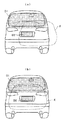
以下。本発明の実施形態の動作を詳細に説明する。図2(a)は、自車両Aに備えた前方カメラ11で前方車両B及び前前方車両Cを撮影する例を示している。また図2(b)は自車両Aに備えた後方カメラ12で後方車両B及び後後方車両Cを撮影する例を示している。尚、前方車両B又は後方車両Bを総称して第1の車両Bと呼び、また前前方車両C又は後後方車両Cを総称して第2の車両Cと呼ぶこともある。
Less than. The operation of the embodiment of the present invention will be described in detail. FIG. 2A shows an example of photographing the front vehicle B and the front front vehicle C with the
本発明では、前方カメラ11又は後方カメラ12で撮像した背景画像の中に前方車両又は後方車両の画像が存在する場合に、個人情報に該当する画像を表示しないようにするため、例えば車両の窓、ナンバープレート、車のキャビン等の領域を自動認識する。そして認識した領域を個人情報保護領域として目隠しするため、マスク画像をリアルタイムで生成して、カメラ画像にオーバーラップさせて表示する。マスク画像としては、例えば該当領域を塗りつぶしたり、モザイク表示する画像がある。
In the present invention, when a front vehicle image or a rear vehicle image is present in the background image captured by the
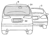
図3は、自車両の前方を撮影した画像の一例を示し、自車両の前に前方車両Bと前前方車両Cがあり、前方車両Bに対して前前方車両Cが小さい場合のリアルタイム画像を示している。一方、個人情報を含む画像をマスクするため、図4で示すように前方車両Bの窓及びナンバープレート部分は、マスク画像D1,D2によってマスクする。 FIG. 3 shows an example of an image obtained by photographing the front of the host vehicle. A real-time image when the front vehicle B and the front front vehicle C are in front of the host vehicle and the front front vehicle C is smaller than the front vehicle B is shown. Show. On the other hand, in order to mask an image including personal information, as shown in FIG. 4, the window and the license plate portion of the preceding vehicle B are masked by mask images D1 and D2.
マスク画像D1,D2は、マスク画像生成部22によって生成されるが、窓は一般的に車両の上部にあり、また窓の色と車両本体の色が異なるため、窓の大体の位置と色情報とを基に窓部を判別しマスク画像D1を生成する。またナンバープレートは、一般的に車両の下部にあり、かつ長方形状であるため、大体の位置と形状でナンバープレート部分を判別しマスク画像D2を生成する。マスク画像D1,D2は合成処理部26でカメラ画像と合成される。
Although the mask images D1 and D2 are generated by the mask
尚、図4では前方車両Bの後方の窓と後方のナンバープレートをマスクする例を示しているが、後方車両Bについては、後方車両Bの前方の窓と前方のナンバープレートをマスクすることになる。また、マスク処理は前方車両や後方車両だけでなく、並走車両の画像についても行うと良い。 FIG. 4 shows an example in which the rear window and the rear license plate of the front vehicle B are masked. However, for the rear vehicle B, the front window and the front license plate of the rear vehicle B are masked. Become. Moreover, it is good to perform a mask process not only on a front vehicle and a back vehicle but on the image of a parallel running vehicle.
例えば、片側2車線以上の広い道路では、自車両の右側や左側を別の車両が並走する場合がある。撮像部10の前方カメラ11や後方カメラ12の視野角が魚眼カメラのように広い場合、或いは自車両の右側及び左側にカメラを取り付けた場合は、並走車両を撮影することができるため、並走車両についてもマスク処理を行う。
For example, on a wide road with two or more lanes on one side, another vehicle may run in parallel on the right or left side of the host vehicle. When the viewing angle of the
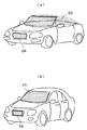
図5は、並走車のマスク処理の一例を示している。図5(a)はスポーツカーのように天井のない車両の一部をマスクする例であり、前方の窓と車両のキャビンの部分をマスク画像D3によってマスクし、ナンバープレートをマスク画像D4によってマスクする。オープンカーのように、天井部のない車両については、窓を含む車両の上部全体をマスクしてもよい。図5(b)はセダンタイプの並走車両の一部をマスクする例であり、前方の窓部分をマスク画像D5によってマスクし、ナンバープレートをマスク画像D6によってマスクする。 FIG. 5 shows an example of mask processing for a parallel running vehicle. FIG. 5A shows an example of masking a part of a vehicle without a ceiling such as a sports car. The front window and the cabin part of the vehicle are masked by a mask image D3, and the license plate is masked by a mask image D4. To do. For vehicles without a ceiling, such as an open car, the entire upper part of the vehicle including the window may be masked. FIG. 5B is an example of masking a part of a sedan type parallel running vehicle, in which a front window portion is masked by a mask image D5 and a license plate is masked by a mask image D6.
一方、通常であれば、第1の車両Bの窓を通して第2の車両Cを確認することができるが、第1の車両Bの窓をマスクした場合、第2の車両Cが隠されてしまい目視できなくなる可能性がある。特に第2の車両Cが第1の車両Bよりも小さい場合は、第1の車両Bの窓だけでなく本体によっても隠されるため、より一層目視しにくくなる。 On the other hand, normally, the second vehicle C can be confirmed through the window of the first vehicle B. However, when the window of the first vehicle B is masked, the second vehicle C is hidden. May not be visible. In particular, when the second vehicle C is smaller than the first vehicle B, the second vehicle C is hidden not only by the window of the first vehicle B but also by the main body, so that it is further difficult to see.
そこで、本発明では、周辺監視部23で第2の車両Cの有無を監視し、第2の車両Cが居る場合に識別画像生成部24で第2の車両Cを模した疑似画像(イラストE)を生成し、合成処理部26でカメラ画像にイラストEを重ねて表示する。イラストEは、単純な図形や、個人的趣味のキャラクター図形などで良い。尚、周辺監視部23における第2の車両Cの監視方法については後述する。
Therefore, in the present invention, the
図6は、前方車両Bの画像に前前方車両CのイラストEを重ねて表示した例を示す。図6(a)は、図3のように前方車両Bによって前前方車両Cの一部が隠れている場合のイラストEの合成位置を示し、図6(b)は、前方車両Bによって前前方車両Cが殆ど隠れている場合のイラストEの合成位置を示す。 FIG. 6 shows an example in which an illustration E of the front front vehicle C is superimposed on the image of the front vehicle B and displayed. FIG. 6A shows the combined position of the illustration E when the front vehicle B is partially hidden by the front vehicle B as shown in FIG. 3, and FIG. The composite position of the illustration E when the vehicle C is almost hidden is shown.
自車両の運転者は、表示部50に表示されたカメラ画像を観察することで前方または後方の状況を確認できるが、個人のプライバシーを考慮して第1の車両Bの窓やナンバープレートはマスクするため、個人情報を保護することができる。また第1の車両Bの前方または後方にいる第2の車両Cの存在をイラストEで確認することができる。
The driver of the host vehicle can confirm the front or rear situation by observing the camera image displayed on the
図7は、画像処理部20の動作を説明するフローチャートである。画像処理部20は、制御部21の制御のもとに以下のステップで動作する。
FIG. 7 is a flowchart for explaining the operation of the
図7において、ステップS1はリアルタイムの画像(マスクしない画像)が必要か否かを判断する。即ち、複数のカメラ11,12…からの画像や車両情報生成部30からの情報等を総合判断して緊急時か否かを判断し、事故もしくは緊急性のある場合、或いは事故回避を行う必要がある場合は、リアルタイム画像が望ましいと判断してステップS2に進み、マスク処理を行なわずに生画像による表示を行う。これによりステップS9において、図3のようなリアルタイム画像を表示する。
In FIG. 7, step S1 determines whether or not a real-time image (an unmasked image) is necessary. That is, it is necessary to judge whether or not it is an emergency by comprehensively judging images from a plurality of
ステップS1の判断がNOの場合、ステップ3では個人情報のマスクが必要か否かを判断する。例えば第1の車両Bの窓が黒い場合等は車室内が窓を通して見えないため、マスク処理をする必要がない。したがってマスクする必要がない場合は、ステップS2に進み図3のようにリアルタイム画像を表示する。 If the determination in step S1 is NO, in step 3, it is determined whether or not a mask for personal information is necessary. For example, when the window of the first vehicle B is black, the interior of the vehicle cannot be seen through the window, so that masking is not necessary. Therefore, if it is not necessary to mask, the process proceeds to step S2 and a real-time image is displayed as shown in FIG.
ステップS3でマスクが必要であると判断した場合は、ステップ4においてマスク領域が全体画像に対して占める割合を判断する。つまり、被写体の窓が小さければ、窓を通して見た室内情報量も限られるのでプライバシーを侵害することはないと考えられる。したがって、撮影した画像の全領域に対して窓のマスク領域が予め設定した割合よりも小さい場合は、ステップS2に進み、マスク処理を行なわずに生画像による表示を行う。尚、ステップS9では、ナンバープレート部分をマスクすると良い。
If it is determined in step S3 that a mask is necessary, in
ステップ4においてマスク領域の画像が占める割合が大きいときは、ステップS5において自車両Aから第1の車両B及び建物までの距離を測定する。カメラ性能に鑑みて、第1の車両Bまでの距離が十分離れている場合は、個人情報等の撮影は困難であるため、ステップS2に進み、リアルタイム画像を表示する。尚、カメラの分解能や周囲状況(明暗、霧など)によって距離係数は変化する。また周辺に建物がある場合は、建物を撮影した中に個人情報に該当する画像(窓、表札等)が含まれる可能性があるため、同様にマスクする。
If the ratio of the mask area image is large in
ステップS5において第1の車両Bまでの距離が近い場合は、ステップS6でマスク領域を塗りつぶしてカメラ画像に重ねる。さらにステップS7では第2の車両の表示が必要か否かを判断する。つまりカメラ画像の一部をマスクしたことで、第1の車両のさらに前又は後ろに居る車両は陰に隠れて見えなくなってしまうため、それらの車両を表示する必要があるかないかを判断する。第2の車両がいない場合や距離が遠い場合は、ステップS10において、図4で示すように第1の車両Bの窓やナンバープレートをマスクした画像のみを合成して表示する。 If the distance to the first vehicle B is short in step S5, the mask area is filled and overlaid on the camera image in step S6. In step S7, it is determined whether display of the second vehicle is necessary. That is, by masking a part of the camera image, the vehicle that is further forward or behind the first vehicle is hidden behind and cannot be seen, so it is determined whether or not these vehicles need to be displayed. When there is no second vehicle or when the distance is long, only an image obtained by masking the window or license plate of the first vehicle B is synthesized and displayed in step S10 as shown in FIG.
また第2の車両の表示が必要な場合は、ステップS8において第2の車両Cを表す疑似画像(イラストE)を合成し、ステップS11において図6に示すようなマスク画像D1,D2とイラストEが合成されたカメラ画像を表示する。 If display of the second vehicle is necessary, a pseudo image (illustration E) representing the second vehicle C is synthesized in step S8, and mask images D1, D2 and illustration E as shown in FIG. 6 are synthesized in step S11. Displays the combined camera image.
尚、図4で示すように前前方車両Cの一部が前方車両Bからはみ出している場合は、前前方車両Cの隠れていない部分の生画像を識別画像として表示してもよいし、前前方車両Cの全体を疑似画像(イラスト)で表示してもよい。例えば、操作部40によって「生画像−イラスト」の表示切り替えを行うようにすると良い。イラストの表示を行った場合は、チラツキ現象を抑え、第2車室C内の個人情報をマスクすることができる。
In addition, as shown in FIG. 4, when a part of the front front vehicle C protrudes from the front vehicle B, a raw image of a part of the front front vehicle C that is not hidden may be displayed as an identification image. The entire forward vehicle C may be displayed as a pseudo image (illustration). For example, display switching of “raw image-illustration” may be performed by the
次に第2の車両Cの存在を確認して疑似画像を生成する方法を具体的に説明する。尚、以下の説明では前方車両Bの前に前前方車両Cが居るか否かを監視する場合を説明するが、後方車両Bの後ろに後後方車両Cが居るか否かを監視する場合も同じ手法を用いることができる。 Next, a method for confirming the existence of the second vehicle C and generating a pseudo image will be specifically described. In the following description, the case where the front front vehicle C is monitored in front of the front vehicle B will be described. However, the case where the rear rear vehicle C is present behind the rear vehicle B may also be monitored. The same approach can be used.
第2の車両Cの存在の有無は、制御部21の制御のもとに周辺監視部23によって行い、疑似画像の生成は識別画像生成部24が行う。周辺監視部23は、前方カメラ11で撮影した画像をもとに前方車両Bへの異常接近や挙動を監視しているが、同時に前方車両Bのひとつ先の前前方車両Cも同時に認識し、その存在と消失を判断する。例えば、以下の(1)〜(5)の判断ポイントをもとにカメラで撮影した画像情報から風景と切り分けて車両を見分ける。(1)前方車両Bの前に居る前前方車両Cをどのように認識するか、(2)画像情報に含まれる物体を車両と認識するか、(3)前前方車両Cが前方車両Bの陰に隠れて見えない期間の位置の判断と消失の判断、(4)前前方車両Cが別の車両にスリ替わったときの判断。以下、具体的に(1)〜(4)の判断ポイントについて説明する。
The presence / absence of the second vehicle C is determined by the
(1)先ず周辺監視部23は、前方車両Bの形状、サイズ、外形色を判断して記録する。また形状、サイズから普通車、小型車、トラック等の大雑把な全長を推測する。前前方車両Cの検出は、前方車両Bの色と異なる物体、もしくは、前方車両のサイズ以上にはみ出した物体を検出する。或いは前方車両Bの窓を通して、または前方車両Bの上下や横から前前方車両Cを認識する。検出個所は、図8で例示するように、前方車両Bの窓F0、上部F1、下部F2、左横F3、右横F4の計5カ所である。
このとき、前方車両Bの窓を通して前前方車両Cが判断できたか、もしくは、前前方車両Cが前方車両Bの上下左右から2カ所以上にはみ出して認識できたかを記録し履歴を残す。こうして認識した結果をC車両存在フラグと呼ぶことにする。尚、前方車両B及び前前方車両Cが居なくなった場合は、認識結果を初期化する。
そして、前方車両Bの全長L1と、前方車両Bの前の物体までの距離L2、及び前方の風景までの距離L3(=∞)を基に、
L1<L2≦L3(=∞)…(1)
の条件が成り立てば、前方車両Bの前の物体を前前方車両Cと看做す。またこの時に、物体を車両と仮定して、前前方車両Cのサイズを推測して、「(仮)サイズ」として記録しておく(後述の「車両スリ替わり」を判定する際に利用する)。
(1) First, the
At this time, it is recorded whether the front vehicle C can be judged through the window of the front vehicle B, or whether the front vehicle C can be recognized by protruding from the top, bottom, left and right of the front vehicle B at two or more places. The recognized result is referred to as a C vehicle presence flag. When the front vehicle B and the front front vehicle C are gone, the recognition result is initialized.
And based on the total length L1 of the forward vehicle B, the distance L2 to the object in front of the forward vehicle B, and the distance L3 (= ∞) to the landscape in front,
L1 <L2 ≦ L3 (= ∞) (1)
If this condition is satisfied, the object in front of the front vehicle B is regarded as the front front vehicle C. At this time, assuming that the object is a vehicle, the size of the front front vehicle C is estimated and recorded as “(temporary) size” (used to determine “vehicle slippage” described later). .
(2)前方車両Bのさらに前方の物体を前前方車両Cと認識するための条件は次の(a),(b)の通りである。このとき正式に車両と認識されるまでの物体を「車両(仮)」と呼ぶ。
(a)車両(仮)が、自車両および前方車両Bと同一車線を走行中である。
(b)同一車線でない時は、走行中に限り自車両A(あるいは前方車両B)から一定距離をM秒間保っている。
車両(仮)が実際に車両であると認識される前に停車した場合は、M秒カウントを一時停止するか、再度、車両(仮)が走行を開始した際にM秒カウントをリセットし、再度M秒カウントを行う。そして自車両Aが走行中だった場合に限り、一定距離を継続する物体は車両であると推察し、前方車両の全長L1と、前方車両の前の物体までの距離L2、及び前方車両の全長L1に所定距離Kを加算した距離L4を基に、
L1<L2≦L4(L4=L1+K)…(2)
の条件が成り立てば、前方車両Bの前の物体を前前方車両Cと看做す。
(2) Conditions for recognizing an object further ahead of the front vehicle B as the front front vehicle C are as follows (a) and (b). An object until it is officially recognized as a vehicle at this time is called a “vehicle (temporary)”.
(A) The vehicle (temporary) is traveling in the same lane as the host vehicle and the preceding vehicle B.
(B) When not in the same lane, the vehicle keeps a certain distance from the own vehicle A (or the preceding vehicle B) for M seconds only during traveling.
If the vehicle (temporary) stops before it is actually recognized as a vehicle, pause the M-second count, or reset the M-second count again when the vehicle (provisional) starts running, Count again for M seconds. Only when the host vehicle A is traveling, it is inferred that the object that continues a certain distance is a vehicle, and the total length L1 of the front vehicle, the distance L2 to the object in front of the front vehicle, and the total length of the front vehicle Based on a distance L4 obtained by adding a predetermined distance K to L1,
L1 <L2 ≦ L4 (L4 = L1 + K) (2)
If this condition is satisfied, the object in front of the front vehicle B is regarded as the front front vehicle C.
(3)次に前述したC車両存在フラグにより、前前方車両Cが恒常的に居るものか、それとも車両の位置関係により一時的に視認できたものかを区分する。つまり、図9(a)のように、前方の普通車Bの前に大型の車両Cが居る場合は、恒常的に大型車両Cを認識できるので、普通車Bの前からN秒間、大型車両Cが不可視になったなら居なくなったと判断する。 (3) Next, according to the above-described C vehicle presence flag, it is classified whether the front vehicle C is always present or can be visually recognized depending on the positional relationship of the vehicle. That is, as shown in FIG. 9 (a), when there is a large vehicle C in front of the front normal vehicle B, the large vehicle C can be recognized constantly, so that the large vehicle C is used for N seconds from the front of the normal vehicle B. If C becomes invisible, it is judged that it is gone.
また図9(b)のように、自車両の前方に大型車両Bが居て、さらにその前に普通車Cが居る場合は、自車両からは普通車Cが時々その一部しか視認できないので、大型車両Bの陰に隠れてずっと見えなくても居なくなったとは判断しない。こうして、B車両およびC車両と思われる物体の検出ポーリングを定期的に行い、前前方車両Cが画像上で不可視だった場合でも、N秒間は「居る」と判断し続ける。 Further, as shown in FIG. 9B, when the large vehicle B is in front of the own vehicle and the ordinary vehicle C is in front of the large vehicle B, only a part of the ordinary vehicle C can be visually recognized from the own vehicle. Even if it is hidden behind the large vehicle B and cannot be seen for a long time, it is not judged that it is gone. In this way, detection polling of the objects considered to be the B vehicle and the C vehicle is periodically performed, and even when the front vehicle C is invisible on the image, it is determined that “there is” for N seconds.
このときの前前方車両Cの位置は、次の(c)〜(e)の通りに判断する。
(c)前前方車両Cは、前方車両Bのさらに前方に居る。
(d)前前方車両Cは、前方車両の左右センター位置で上下位置は最後に認識した位置とする。
(e)前前方車両Cの前方車両Bとの相対距離は最後に認識した相対距離を維持する。
また、前前方車両Cが画像上で不可視の状態がN秒間継続された場合でも、一時的に視認できたと履歴されている場合は、居ないとは判断できないのでN秒後でも「居る」と判断する。但し自車両の前方の一定距離内に車両が存在しなくなった場合は、前方車両Bだけでなく前前方車両Cも「居なくなった」と判断する。
The position of the front front vehicle C at this time is determined as follows (c) to (e).
(C) The front front vehicle C is further ahead of the front vehicle B.
(D) The front front vehicle C is the left and right center position of the front vehicle and the vertical position is the last recognized position.
(E) The relative distance between the front vehicle C and the front vehicle B is the last recognized relative distance.
In addition, even if the front front vehicle C has been invisible in the image for N seconds, if it has been recorded as being temporarily visible, it cannot be determined that it is not present, so it will be “present” even after N seconds. to decide. However, if the vehicle no longer exists within a certain distance in front of the host vehicle, it is determined that not only the front vehicle B but also the front front vehicle C is “absent”.
(4)前前方車両Cの、推測サイズ、もしくは外形色が大きく変化した場合には、前前方車両Cが別の車両と入れ替わったと判断する。これを「車両スリ替わり」と呼び、C車両存在フラグをクリアする。車両がスリ替わったことに伴って、以前の車両に対してフラグ・情報を記録していた場合、これらの旧い情報はスリ替わったものと判定したタイミングでクリアし破棄する。 (4) When the estimated size or the outer color of the front front vehicle C changes greatly, it is determined that the front front vehicle C has been replaced with another vehicle. This is called “vehicle slippage”, and the C vehicle presence flag is cleared. When the flag / information is recorded for the previous vehicle when the vehicle is replaced, the old information is cleared and discarded at the timing when it is determined that the vehicle has been replaced.
こうして、前方車両Bの前に前前車両Cが居ると判断した場合は、前前車両Cの疑似画像(イラストE)を生成し、図6のようにイラストEをカメラ画像に合成して表示する。イラストEの位置は、前前車両Cの位置に応じて変化する。また前前方車両Cがスリ替わった場合は、スリ替わり後の車両に合わせて色やサイズを変化させ、過去のイラストは削除する。 Thus, when it is determined that the front vehicle C is in front of the preceding vehicle B, a pseudo image (illustration E) of the front vehicle C is generated, and the illustration E is combined with the camera image and displayed as shown in FIG. To do. The position of the illustration E changes according to the position of the front vehicle C. When the front front vehicle C changes, the color and size are changed according to the vehicle after the change, and the past illustrations are deleted.
図10は、前方車両Bの前の物体が前前方車両Cと認識されるまでのフローチャートを示す。尚、以下の説明では、前方車両BをB車両と呼び、前前方車両CをC車両と呼ぶこともある。 FIG. 10 shows a flowchart until the object in front of the front vehicle B is recognized as the front front vehicle C. In the following description, the front vehicle B may be referred to as a B vehicle, and the front front vehicle C may be referred to as a C vehicle.
図10において、ステップ21ではB車両の情報を判定し記録する。つまりB車両が視認できる場合、形状やサイズ、及び自車両との距離を推測して記録する。またB車両の外形色の情報を記録する。ステップS22ではC車両(仮)情報を判定して記録する。ここでは、C車両と思われる物体の形状やサイズ、及び自車両からの距離を推測して記録する。またC車両の存在フラグやC車両(仮)の検出タイマーを設定する。ステップS23では、C車両(仮)が検出できたか否かを判断し、検出できなかった場合はステップS24に進み、図12で後述するC車両、C車両(仮)が検出できない場合のフローに進む。
In FIG. 10, in
ステップS23でC車両(仮)が検出できた場合は、ステップS25で車両のスリ替わりを検出する。車両のスリ替わりが検出されたときはステップS26でC車両(仮)として記録情報を再設定する。再設定後、又はステップS25で車両のスリ替わりが検出されなかった場合は、ステップS27でC車両(仮)とのL2距離が(1)式の条件を満たすか否かを判断する。(1)式の条件を満たさない場合はステッフS24に進み、満たす場合はステップS28でC車両(仮)が自車両Aの車線上にいるか否かを判断する。 If the C vehicle (temporary) has been detected in step S23, the change of the vehicle is detected in step S25. When the change of the vehicle is detected, the record information is reset as the C vehicle (temporary) in step S26. After the resetting or when the change of the vehicle is not detected in step S25, it is determined in step S27 whether or not the L2 distance from the C vehicle (temporary) satisfies the condition of the expression (1). If the condition of the expression (1) is not satisfied, the process proceeds to step S24. If satisfied, it is determined whether or not the C vehicle (temporary) is on the lane of the own vehicle A in step S28.
ステップS28の判断でC車両(仮)が同じ車線上にいない場合は、ステッフS24に進み、同じ車線上にいる場合はステップS29で自車両Aが走行中か否かを判断する。自車両Aが走行中でない場合は、ステッフS24に進み、走行中であればステップS30でC車両(仮)との距離L2が(2)式の条件を満たすか否かを判断する。(2)式の条件を満たさない場合はステッフS24に進み、満たす場合はステップS31でC車両(仮)は単なる物体ではなく車両と判断する。このとき、C車両フラグをオンにし、C車両消失タイマーをセットする。尚、C車両消失タイマーは、C車両が検出される度にリセットされる。 If it is determined in step S28 that the vehicle C (temporary) is not on the same lane, the process proceeds to step S24. If the vehicle C is on the same lane, it is determined in step S29 whether the host vehicle A is traveling. If the host vehicle A is not traveling, the process proceeds to step S24. If the host vehicle A is traveling, it is determined in step S30 whether the distance L2 to the C vehicle (temporary) satisfies the condition of the expression (2). If the condition of equation (2) is not satisfied, the process proceeds to step S24. If the condition is satisfied, it is determined in step S31 that the C vehicle (temporary) is not a mere object but a vehicle. At this time, the C vehicle flag is turned on and the C vehicle disappearance timer is set. The C vehicle disappearance timer is reset every time a C vehicle is detected.
図11は、C車両を画像から検出するためのアルゴリズムを示すフローチャートである。図11において、ステップS41ではB車両が検出できたか否かを判断する。検出できた場合は、ステップS42ではB車両の窓を通してその前方にいるC車両と思える物体が検出できたか否かを判断する。C車両と思える物体が検出できた場合は、ステップS43に進み、C車両の存在フラグをオンにし、ステップS44では、C車両と思える物体が明確に検出できたとして、識別画像生成部24でC車両を示すイラストを生成し、例えば図6(a)のようなイラストEを表示する。 FIG. 11 is a flowchart showing an algorithm for detecting the C vehicle from the image. In FIG. 11, it is determined in step S41 whether or not the B vehicle has been detected. If it can be detected, it is determined in step S42 whether or not an object that seems to be a C vehicle in front of the B vehicle can be detected. If an object that seems to be a C vehicle can be detected, the process proceeds to step S43, the existence flag of the C vehicle is turned on, and an object that seems to be a C vehicle can be clearly detected in step S44. An illustration showing the vehicle is generated, and for example, an illustration E as shown in FIG.
またステップS41でB車両が検出できなかった場合は、ステップS45でB車両及びC車両の情報を初期化する。この場合は、ステップS46で自車両の前方に車両と思える物体はないと判断する。またステップS42で、B車両の窓を通してC車両と思える物体が検出できなかった場合は、ステップS47で、B車両からはみ出しているC車両と思える物体があるか否かを判断する。C車両と思える物体がある場合は、ステップS48でB車両からはみ出しているC車両と思える物体が同時に2か所以上検出されたか否かを判断する。C車両と思える物体が同時に2か所以上検出された場合(図9(a)のような場合)は、ステップS43に進みC車両の存在フラグをオンにする。 If the vehicle B cannot be detected in step S41, information on the vehicle B and vehicle C is initialized in step S45. In this case, it is determined in step S46 that there is no object that seems to be a vehicle ahead of the host vehicle. If an object that seems to be a C vehicle cannot be detected through the window of the B vehicle in step S42, it is determined in step S47 whether there is an object that seems to be a C vehicle protruding from the B vehicle. If there is an object that seems to be a C vehicle, it is determined in step S48 whether or not two or more objects that seem to be a C vehicle protruding from the B vehicle are detected at the same time. If two or more objects that seem to be a C vehicle are detected at the same time (as shown in FIG. 9A), the process proceeds to step S43 and the presence flag of the C vehicle is turned on.
ステップS48でC車両と思える物体が同時に2か所以上検出されなかった場合(図9(b)のような場合で前前方車両Cが隠れているとき)は、ステップS50に進み、C車両存在フラグは操作しない。この状態ではC車両と思える物体を明確には視認できず、ステップS51ではC車両と思える物体の一部を検出したものと判断する。このとき、C車両を示すイラストEは図6(b)のように表示される。 If two or more objects that are considered to be the C vehicle are not detected at the same time in step S48 (when the front vehicle C is hidden in the case as shown in FIG. 9B), the process proceeds to step S50, where the C vehicle exists. The flag is not manipulated. In this state, the object that seems to be the C vehicle cannot be clearly seen, and it is determined in step S51 that a part of the object that seems to be the C vehicle has been detected. At this time, an illustration E showing the C vehicle is displayed as shown in FIG.
図12は、C車両及びC車両(仮)が検出できなかった場合のフローチャートである。図12において、ステップS61ではC車両(仮)が既に車両判定されているか否かを判断する。C車両(仮)が車両判定されている場合は、ステップS62で、C車両消失タイマーはゼロか否かを判定する。C車両消失タイマーがゼロである場合は、ステップS63でC車両存在フラグはオンか否かを判断する。 FIG. 12 is a flowchart when the C vehicle and the C vehicle (temporary) cannot be detected. In FIG. 12, in step S61, it is determined whether or not the C vehicle (temporary) has already been determined. If the C vehicle (temporary) is determined to be a vehicle, it is determined in step S62 whether or not the C vehicle disappearance timer is zero. If the C vehicle disappearance timer is zero, it is determined in step S63 whether the C vehicle presence flag is on.
ステップS62で、C車両消失タイマーゼロでない場合、及びステップS63でC車両存在フラグがオンでない場合は、ステップS64に進み、C車両は見えなくなったが居なくなった訳ではないと判断し、過去のC車両情報をもとにイラストの表示を行う。ステップS65では、C車両の位置はB車両前方のセンター位置とし、自車両Aとの相対距離は過去の情報を用いる。ステップS66は、物体は見えないが車両として認識し続ける期間に相当する。 If it is determined in step S62 that the C vehicle disappearance timer is not zero, and if the C vehicle presence flag is not on in step S63, the process proceeds to step S64, where it is determined that the C vehicle has disappeared but has not disappeared. C The illustration is displayed based on the vehicle information. In step S65, the position of the vehicle C is the center position in front of the vehicle B, and the past distance is used as the relative distance to the host vehicle A. Step S66 corresponds to a period during which an object is not visible but is still recognized as a vehicle.
ステップS63でC車両存在フラグがオンのときは、恒常的に視認可能な状況で一定時間C車両が見えないとして、C車両は居なくなったと判断し、必要であればC車両情報をクリアにする。ステップS68では、C車両は居なくなったと判断する。 When the C vehicle presence flag is on in step S63, it is determined that the C vehicle has disappeared for a certain period of time in a constantly visible state, and the C vehicle information is cleared if necessary. . In step S68, it is determined that the C vehicle is gone.
またステップS61でC車両(仮)が車両判定されていないと判断した場合は、ステップS69で、C車両(仮)検出タイマーがゼロか否かを判断する。C車両(仮)検出タイマーがゼロの場合はステップS70に進み、C車両は居なくなったと判断し、必要であればC車両の情報をクリアし、ステップS71では、車両と認識する前の物体が居なくなったと判断する。またステップS69で、C車両(仮)検出タイマーがゼロでない場合は、ステップS72に進み、C車両は見えなくなったが居なくなった訳ではないと判断し、過去のC車両(仮)情報をもとにイラストの表示を行う。ステップS73では、C車両の位置はB車両前方のセンター位置とする。ステップS74は、物体はあるが車両としては認識されない期間に相当する。 If it is determined in step S61 that the C vehicle (temporary) has not been determined, it is determined in step S69 whether the C vehicle (temporary) detection timer is zero. If the C vehicle (temporary) detection timer is zero, the process proceeds to step S70, where it is determined that there is no C vehicle, and if necessary, the information on the C vehicle is cleared. Judge that it is gone. If the C vehicle (temporary) detection timer is not zero in step S69, the process proceeds to step S72, where it is determined that the C vehicle has disappeared but has not disappeared. And display an illustration. In step S73, the position of the C vehicle is the center position in front of the B vehicle. Step S74 corresponds to a period in which there is an object but it is not recognized as a vehicle.
以上説明したように本発明の実施形態によれば、自車両の前方や後方の周囲の状況を撮影して運転者の運転を補助するとともに、撮影した前方車両や後方車両の窓部等をマスクすることで個人情報を保護することができる。また、マスク処理によって前前方車両や後後方車両が隠される場合でも疑似画像を表示して認識することができる。また、カメラ性能が向上した場合に、カメラで撮影した画像の個人情報部分をマスクすることで盗撮行為に該当するのを避けることができる。 As described above, according to the embodiments of the present invention, the situation around the front and rear of the host vehicle is photographed to assist the driver, and the photographed front vehicle and the windows of the rear vehicle are masked. By doing so, personal information can be protected. Further, even when the front front vehicle or the rear rear vehicle is hidden by the mask process, a pseudo image can be displayed and recognized. Further, when the camera performance is improved, it is possible to avoid falling into a voyeurism by masking the personal information portion of the image taken by the camera.
尚、以上説明した実施形態については各種の変形例が考えられる。例えば、カメラは車両の前方及び後方を撮影する以外に横方向を撮影可能にしてもよい。また特許請求の範囲を逸脱しない範囲内で種々の変形が可能である。 Various modifications can be considered for the embodiment described above. For example, the camera may be capable of photographing in the lateral direction in addition to photographing the front and rear of the vehicle. Various modifications can be made without departing from the scope of the claims.
10…撮像部
11,12,n…カメラ
20…画像処理部
21…制御部
22…マスク画像生成部
23…周辺監視部
24…識別画像生成部
25…カメラ画像処理部
26…合成処理部
30…車両情報生成部
31…ナビゲーション装置
40…操作部
50…表示部
DESCRIPTION OF
Claims (6)
前記複数のカメラで撮影したカメラ画像のうち、自車両の前方又は後方に近接する第1の車両の画像に含まれる個人情報保護領域を目隠しするマスク画像を生成するマスク画像生成部と、
前記カメラ画像を利用して前記第1の車両の前方又は後方での第2の車両の有無を監視する周辺監視部と、
前記周辺監視部によって前記第2の車両の存在を判別したとき、前記第2の車両の存在を示す識別画像を生成する識別画像生成部と、
前記カメラ画像に前記マスク画像及び前記識別画像を合成して表示部に表示する合成処理部と、を具備したことを特徴とする車両用画像表示装置。 An imaging unit including a plurality of cameras that respectively capture images of the front and rear of the vehicle and capable of capturing the surroundings of the vehicle;
A mask image generation unit that generates a mask image that blinds a personal information protection area included in an image of the first vehicle that is close to the front or rear of the host vehicle among the camera images captured by the plurality of cameras;
A periphery monitoring unit that monitors the presence or absence of a second vehicle in front of or behind the first vehicle using the camera image;
An identification image generating unit that generates an identification image indicating the presence of the second vehicle when the periphery monitoring unit determines the presence of the second vehicle;
An image display apparatus for a vehicle, comprising: a combining processing unit that combines the mask image and the identification image with the camera image and displays the combined image on a display unit.
Priority Applications (3)
| Application Number | Priority Date | Filing Date | Title |
|---|---|---|---|
| JP2009189260A JP5210994B2 (en) | 2009-08-18 | 2009-08-18 | Image display device for vehicle |
| US12/779,359 US8400329B2 (en) | 2009-08-18 | 2010-05-13 | Image display apparatus for vehicle |
| CN2010102250376A CN101998113B (en) | 2009-08-18 | 2010-07-05 | Image display apparatus for vehicle |
Applications Claiming Priority (1)
| Application Number | Priority Date | Filing Date | Title |
|---|---|---|---|
| JP2009189260A JP5210994B2 (en) | 2009-08-18 | 2009-08-18 | Image display device for vehicle |
Publications (3)
| Publication Number | Publication Date |
|---|---|
| JP2011039983A JP2011039983A (en) | 2011-02-24 |
| JP2011039983A5 JP2011039983A5 (en) | 2012-07-12 |
| JP5210994B2 true JP5210994B2 (en) | 2013-06-12 |
Family
ID=43604890
Family Applications (1)
| Application Number | Title | Priority Date | Filing Date |
|---|---|---|---|
| JP2009189260A Active JP5210994B2 (en) | 2009-08-18 | 2009-08-18 | Image display device for vehicle |
Country Status (3)
| Country | Link |
|---|---|
| US (1) | US8400329B2 (en) |
| JP (1) | JP5210994B2 (en) |
| CN (1) | CN101998113B (en) |
Families Citing this family (24)
| Publication number | Priority date | Publication date | Assignee | Title |
|---|---|---|---|---|
| KR101735684B1 (en) * | 2010-12-14 | 2017-05-15 | 한국전자통신연구원 | Vehicle video recording and servicing apparatus and method, apparatus and method acquiring local area information using the same |
| CN103106634A (en) * | 2012-12-26 | 2013-05-15 | 上海合合信息科技发展有限公司 | Method and system for protecting bank card individual information |
| CN104050829A (en) * | 2013-03-14 | 2014-09-17 | 联想(北京)有限公司 | Information processing method and apparatus |
| JP6354356B2 (en) * | 2014-06-10 | 2018-07-11 | 株式会社デンソー | Forward situation judgment device |
| WO2016111072A1 (en) | 2015-01-08 | 2016-07-14 | ソニー株式会社 | Image processing device, image pickup device, and image processing method |
| JP6519253B2 (en) * | 2015-03-18 | 2019-05-29 | 横浜ゴム株式会社 | Driving support device |
| US10040394B2 (en) | 2015-06-17 | 2018-08-07 | Geo Semiconductor Inc. | Vehicle vision system |
| EP3148174B1 (en) * | 2015-09-22 | 2019-12-18 | Ficosa Adas, S.L.U. | Device for capturing optical information |
| WO2017168949A1 (en) * | 2016-03-29 | 2017-10-05 | ソニー株式会社 | Information processing device, imaging device, image reproduction device, method and program |
| JP6822851B2 (en) | 2017-01-06 | 2021-01-27 | 東芝テック株式会社 | Recording device and its program |
| JP6915995B2 (en) * | 2017-02-01 | 2021-08-11 | 株式会社デンソーテン | Drive recorder |
| JP6843965B2 (en) * | 2017-03-30 | 2021-03-17 | 三菱重工機械システム株式会社 | Vehicle management system, in-vehicle device, vehicle management method, program |
| JP6967801B2 (en) * | 2017-05-19 | 2021-11-17 | 株式会社ユピテル | Drive recorders, display devices and programs for drive recorders, etc. |
| JP7030534B2 (en) * | 2018-01-16 | 2022-03-07 | キヤノン株式会社 | Image processing device and image processing method |
| CN108327719A (en) * | 2018-01-31 | 2018-07-27 | 京东方科技集团股份有限公司 | The method and device of assisting vehicle travel |
| JP7095537B2 (en) * | 2018-10-02 | 2022-07-05 | トヨタ自動車株式会社 | Image processing equipment, programs, information processing systems, and control methods |
| JP7190110B2 (en) * | 2019-02-27 | 2022-12-15 | トヨタ自動車株式会社 | Image processing device and image processing method |
| US11323633B2 (en) | 2019-07-01 | 2022-05-03 | Bendix Commercial Vehicle Systems, Llc | Automated creation of a freeform mask for automotive cameras |
| JP7300349B2 (en) * | 2019-09-04 | 2023-06-29 | 株式会社デンソーテン | Image recording system, image providing device, and image providing method |
| JP2021043571A (en) * | 2019-09-09 | 2021-03-18 | ソニーセミコンダクタソリューションズ株式会社 | Information processing device, mobile device, and information process system, method and program |
| JP2021083004A (en) | 2019-11-21 | 2021-05-27 | アイシン精機株式会社 | Sensor system |
| US11210519B2 (en) * | 2020-01-15 | 2021-12-28 | Trimble Inc. | Providing augmented reality images to an operator of a machine |
| CN112291525A (en) * | 2020-10-29 | 2021-01-29 | 重庆长安汽车股份有限公司 | Automobile perspective system and method for breaking through distance, vehicle and storage medium |
| JP2022136645A (en) * | 2021-03-08 | 2022-09-21 | 本田技研工業株式会社 | Vehicle control device and vehicle control method |
Family Cites Families (17)
| Publication number | Priority date | Publication date | Assignee | Title |
|---|---|---|---|---|
| US6498620B2 (en) * | 1993-02-26 | 2002-12-24 | Donnelly Corporation | Vision system for a vehicle including an image capture device and a display system having a long focal length |
| JP3605525B2 (en) * | 1999-02-10 | 2004-12-22 | 株式会社日立製作所 | Vehicle traffic monitoring and management device |
| DE10158990C1 (en) * | 2001-11-30 | 2003-04-10 | Bosch Gmbh Robert | Video surveillance system incorporates masking of identified object for maintaining privacy until entry of authorisation |
| US7212653B2 (en) * | 2001-12-12 | 2007-05-01 | Kabushikikaisha Equos Research | Image processing system for vehicle |
| JP3972722B2 (en) * | 2002-04-24 | 2007-09-05 | 株式会社エクォス・リサーチ | In-vehicle image processing device |
| JP4526868B2 (en) | 2004-05-12 | 2010-08-18 | アルパイン株式会社 | Top-view image generation apparatus and top-view image display method |
| JP4487660B2 (en) | 2004-07-07 | 2010-06-23 | ソニー株式会社 | Image protection device and imaging device |
| JP4606336B2 (en) * | 2005-02-21 | 2011-01-05 | 株式会社オートネットワーク技術研究所 | Vehicle periphery visual recognition device |
| JP4513662B2 (en) | 2005-06-15 | 2010-07-28 | 株式会社デンソー | In-vehicle radar device, vehicle control system |
| JP4410755B2 (en) | 2005-12-09 | 2010-02-03 | 株式会社日立製作所 | Image processing apparatus and monitoring system |
| JP4203512B2 (en) * | 2006-06-16 | 2009-01-07 | 本田技研工業株式会社 | Vehicle periphery monitoring device |
| JP4826355B2 (en) * | 2006-06-20 | 2011-11-30 | 日産自動車株式会社 | Vehicle surrounding display device |
| JP2008009761A (en) | 2006-06-29 | 2008-01-17 | Toyota Motor Corp | In-car environment recorder |
| WO2008038333A1 (en) * | 2006-09-25 | 2008-04-03 | Pioneer Corporation | Data recording device, data recording method, data recording program, and computer readable recording medium |
| JP4856656B2 (en) * | 2008-01-22 | 2012-01-18 | 富士重工業株式会社 | Vehicle detection device |
| WO2010052550A2 (en) * | 2008-11-05 | 2010-05-14 | Easywalk Capital S.A. | System and method for creating and broadcasting interactive panoramic walk-through applications |
| US8737605B2 (en) * | 2010-11-17 | 2014-05-27 | Electronics And Telecommunications Research Institute | Privacy region masking device and method in vehicle black box |
-
2009
- 2009-08-18 JP JP2009189260A patent/JP5210994B2/en active Active
-
2010
- 2010-05-13 US US12/779,359 patent/US8400329B2/en active Active
- 2010-07-05 CN CN2010102250376A patent/CN101998113B/en active Active
Also Published As
| Publication number | Publication date |
|---|---|
| US8400329B2 (en) | 2013-03-19 |
| CN101998113A (en) | 2011-03-30 |
| US20110043341A1 (en) | 2011-02-24 |
| CN101998113B (en) | 2013-06-19 |
| JP2011039983A (en) | 2011-02-24 |
Similar Documents
| Publication | Publication Date | Title |
|---|---|---|
| JP5210994B2 (en) | Image display device for vehicle | |
| JP5099451B2 (en) | Vehicle periphery confirmation device | |
| JP5347257B2 (en) | Vehicle periphery monitoring device and video display method | |
| KR101083885B1 (en) | Intelligent driving assistant systems | |
| JP6311646B2 (en) | Image processing apparatus, electronic mirror system, and image processing method | |
| JP4615380B2 (en) | Image transmission device | |
| CN111699680B (en) | Automobile data recorder, display control method, and storage medium | |
| JP5093611B2 (en) | Vehicle periphery confirmation device | |
| JP2008230296A (en) | Vehicle drive supporting system | |
| JP4200343B2 (en) | Monitor device | |
| JP2007164549A (en) | Image pickup apparatus, video signal selector, driving support apparatus, and automobile | |
| US9232195B2 (en) | Monitoring of the close proximity around a commercial vehicle | |
| JP2005242606A (en) | Image generation system, image generation program and image generation method | |
| JP5948170B2 (en) | Information display device, information display method, and program | |
| JP2009049943A (en) | Top view display unit using range image | |
| TWI533694B (en) | Obstacle detection and display system for vehicle | |
| CN105857180A (en) | Hazy weather vehicle driving auxiliary system and method | |
| CN108791062A (en) | Dynamic information system and operating method | |
| JP4986070B2 (en) | Ambient monitoring device for vehicles | |
| JP2005214730A (en) | Image display device, method, and program for vehicle | |
| WO2019030963A1 (en) | Display control device for vehicle, stop position determination device for vehicle, display control system for vehicle, display control method for vehicle and program | |
| JP2008182312A (en) | Picked-up image display device | |
| JP2022140026A (en) | Image processing device, image processing method and program | |
| CN113386669A (en) | Driving assistance system and vehicle | |
| KR100904702B1 (en) | Video apparatus for bus |
Legal Events
| Date | Code | Title | Description |
|---|---|---|---|
| A521 | Request for written amendment filed |
Free format text: JAPANESE INTERMEDIATE CODE: A523 Effective date: 20120528 |
|
| A621 | Written request for application examination |
Free format text: JAPANESE INTERMEDIATE CODE: A621 Effective date: 20120528 |
|
| A977 | Report on retrieval |
Free format text: JAPANESE INTERMEDIATE CODE: A971007 Effective date: 20130207 |
|
| TRDD | Decision of grant or rejection written | ||
| A01 | Written decision to grant a patent or to grant a registration (utility model) |
Free format text: JAPANESE INTERMEDIATE CODE: A01 Effective date: 20130219 |
|
| A61 | First payment of annual fees (during grant procedure) |
Free format text: JAPANESE INTERMEDIATE CODE: A61 Effective date: 20130225 |
|
| FPAY | Renewal fee payment (event date is renewal date of database) |
Free format text: PAYMENT UNTIL: 20160301 Year of fee payment: 3 |
|
| R150 | Certificate of patent or registration of utility model |
Ref document number: 5210994 Country of ref document: JP Free format text: JAPANESE INTERMEDIATE CODE: R150 Free format text: JAPANESE INTERMEDIATE CODE: R150 |
|
| R250 | Receipt of annual fees |
Free format text: JAPANESE INTERMEDIATE CODE: R250 |
|
| R250 | Receipt of annual fees |
Free format text: JAPANESE INTERMEDIATE CODE: R250 |
|
| R250 | Receipt of annual fees |
Free format text: JAPANESE INTERMEDIATE CODE: R250 |
|
| S111 | Request for change of ownership or part of ownership |
Free format text: JAPANESE INTERMEDIATE CODE: R313113 |
|
| R350 | Written notification of registration of transfer |
Free format text: JAPANESE INTERMEDIATE CODE: R350 |
|
| R250 | Receipt of annual fees |
Free format text: JAPANESE INTERMEDIATE CODE: R250 |
|
| R250 | Receipt of annual fees |
Free format text: JAPANESE INTERMEDIATE CODE: R250 |
|
| R250 | Receipt of annual fees |
Free format text: JAPANESE INTERMEDIATE CODE: R250 |
|
| R250 | Receipt of annual fees |
Free format text: JAPANESE INTERMEDIATE CODE: R250 |
|
| R250 | Receipt of annual fees |
Free format text: JAPANESE INTERMEDIATE CODE: R250 |
|
| R250 | Receipt of annual fees |
Free format text: JAPANESE INTERMEDIATE CODE: R250 |