JP4526868B2 - Top-view image generation apparatus and top-view image display method - Google Patents

Top-view image generation apparatus and top-view image display method Download PDF

Info

Publication number
JP4526868B2
JP4526868B2 JP2004142461A JP2004142461A JP4526868B2 JP 4526868 B2 JP4526868 B2 JP 4526868B2 JP 2004142461 A JP2004142461 A JP 2004142461A JP 2004142461 A JP2004142461 A JP 2004142461A JP 4526868 B2 JP4526868 B2 JP 4526868B2
Authority
JP
Japan
Prior art keywords
image
obstacle
top view
host vehicle
vehicle
Prior art date
Legal status (The legal status is an assumption and is not a legal conclusion. Google has not performed a legal analysis and makes no representation as to the accuracy of the status listed.)
Expired - Fee Related
Application number
JP2004142461A
Other languages
Japanese (ja)
Other versions
JP2005324593A (en
Inventor
孝之 荻野
Current Assignee (The listed assignees may be inaccurate. Google has not performed a legal analysis and makes no representation or warranty as to the accuracy of the list.)
Alpine Electronics Inc
Original Assignee
Alpine Electronics Inc
Priority date (The priority date is an assumption and is not a legal conclusion. Google has not performed a legal analysis and makes no representation as to the accuracy of the date listed.)
Filing date
Publication date
Application filed by Alpine Electronics Inc filed Critical Alpine Electronics Inc
Priority to JP2004142461A priority Critical patent/JP4526868B2/en
Publication of JP2005324593A publication Critical patent/JP2005324593A/en
Application granted granted Critical
Publication of JP4526868B2 publication Critical patent/JP4526868B2/en
Expired - Fee Related legal-status Critical Current
Anticipated expiration legal-status Critical

Links

Images

Description

本発明は、自車両の上方の仮想視点から見たトップビュー画像を生成するトップビュー画像生成装置及びトップビュー画像表示方法に関し、特に、自車両及び自車両の周辺を表示するトップビュー画像生成装置及びトップビュー画像表示方法に関する。   The present invention relates to a top view image generation apparatus and a top view image display method for generating a top view image viewed from a virtual viewpoint above the own vehicle, and in particular, a top view image generation apparatus that displays the periphery of the own vehicle and the own vehicle. And a top-view image display method.

従来、自車両に複数台のカメラを設置し、複数台のカメラにより自車両の周囲の画像を撮影して、撮影した画像を自車両内に設置したディスプレイ等の表示装置に表示する技術が提案されている。   Conventionally, a technique has been proposed in which a plurality of cameras are installed in the host vehicle, images around the host vehicle are captured by the plurality of cameras, and the captured images are displayed on a display device such as a display installed in the host vehicle. Has been.

自車両の運転者は、表示装置に表示された画像を確認することで、自車両と障害物との距離を把握し、自車両と障害物との衝突や追突等の交通事故を防ぐように運転を行う。   By checking the image displayed on the display device, the driver of the host vehicle knows the distance between the host vehicle and the obstacle, and prevents traffic accidents such as a collision between the host vehicle and the obstacle or a rear-end collision. Do the driving.

また、自車両に複数台のカメラを設置し、複数台のカメラにより撮影された画像をもとに、自車両の上方の仮想視点から見たトップビュー画像を生成し、このトップビュー画像をディスプレイ等の表示装置に表示することで、自車両の周辺を監視する技術が提案されている(例えば特許文献1など)。
国際公開第00/64175号パンフレット
In addition, a plurality of cameras are installed in the host vehicle, a top view image viewed from a virtual viewpoint above the host vehicle is generated based on images taken by the plurality of cameras, and the top view image is displayed. A technique for monitoring the periphery of the host vehicle by displaying on a display device such as the above has been proposed (for example, Patent Document 1).
International Publication No. 00/64175 Pamphlet

図14は、特許文献1に記載の画像処理装置により生成されるトップビュー画像100の例を示す図である。図14において、100はトップビュー画像であり、ディスプレイ等の表示装置に必要に応じて表示される。101は自車両であり、画像処理装置の画像記憶部に記憶された自車両画像データに基づいて、トップビュー画像100の略中央に上方の仮想視点から見た状態で表示される。102は障害物であり、自車両101に設置された複数台のカメラにより撮影された画像に基づいて障害物と認識されたものである。ここで、障害物102は、例えば塀や建物の壁、トラックなどのある程度の高さを持つ障害物であり、自車両101の進行方向(例えば前方)に対して略平行に所定の範囲に渡って存在している。103は遮蔽部であり、車の左をカメラにより撮影した場合に、障害物102により遮られる無画像の部分である。従って、トップビュー画像100では、遮蔽部103の画像を表示することができない。   FIG. 14 is a diagram illustrating an example of a top view image 100 generated by the image processing apparatus described in Patent Document 1. In FIG. 14, reference numeral 100 denotes a top view image, which is displayed on a display device such as a display as necessary. Reference numeral 101 denotes the host vehicle, which is displayed in a state viewed from the upper virtual viewpoint at the approximate center of the top view image 100 based on the host vehicle image data stored in the image storage unit of the image processing apparatus. Reference numeral 102 denotes an obstacle, which is recognized as an obstacle based on images taken by a plurality of cameras installed in the host vehicle 101. Here, the obstacle 102 is an obstacle having a certain height, such as a fence, a wall of a building, or a truck, and extends over a predetermined range substantially parallel to the traveling direction (for example, forward) of the host vehicle 101. Exist. Reference numeral 103 denotes a shielding portion, which is a non-image portion that is blocked by the obstacle 102 when the left side of the car is photographed by the camera. Therefore, in the top view image 100, the image of the shielding part 103 cannot be displayed.

104は背景部であり、自車両101に設置された複数台のカメラにより撮影された画像に基づいて生成される背景画像である。この背景画像は、自車両101が走行した場合に、トップビュー画像100の略中央に自車両101を固定した状態で下方にスクロール表示される。このとき、障害物102も下方にスクロール表示される。   Reference numeral 104 denotes a background part, which is a background image generated based on images taken by a plurality of cameras installed in the host vehicle 101. When the host vehicle 101 travels, the background image is scrolled downward with the host vehicle 101 fixed at the approximate center of the top view image 100. At this time, the obstacle 102 is also scrolled downward.

しかしながら、特許文献1に記載の技術によれば、トップビュー画像100において、自車両101の表示位置が略中央に固定されてしまう。そのため、障害物102の左側に存在する遮蔽部103は、詳しい画像が得られていないにも関わらず、トップビュー画像100のかなりの部分を占めて表示されてしまい、自車両101の運転者にとって無駄な情報になってしまうという問題があった。   However, according to the technique described in Patent Document 1, in the top view image 100, the display position of the host vehicle 101 is fixed at substantially the center. For this reason, the shielding part 103 present on the left side of the obstacle 102 is displayed by occupying a considerable portion of the top view image 100 even though a detailed image is not obtained. There was a problem that it became useless information.

本発明は、このような問題を解決するために成されたものであり、トップビュー画像における無駄な情報の表示を削減して、運転者にとって有効な情報を多く表示できるようにすることを目的とする。   The present invention has been made to solve such a problem, and an object of the present invention is to reduce the display of useless information in the top view image and to display a lot of information effective for the driver. And

上記した課題を解決するために、本発明では、画像撮影部により撮影された画像から生成される合成画像のうち、自車両から自車両の周辺の障害物までの距離及び方向を示す障害物情報に応じて決まる所定の範囲がトップビュー画像として表示されるようにしている。具体的に、自車両から自車両のある一方向に存在する障害物までの距離が、合成画像の中央に自車両を配置したときの当該自車両から当該合成画像の端までの長さよりも短い場合に、その障害物がトップビュー画像の一辺として表示されるように表示範囲を可変としている。また、画像撮影部の撮影可能範囲または障害物検知部により障害物を検知可能な範囲内で、且つ、自車両の両側に障害物が存在する場合に、自車両の両側の障害物をそれぞれ左辺および右辺としたトップビュー予備画像を切り出し、切り出したトップビュー予備画像の左右の辺がトップビュー画像の表示領域内に入り、自車両の画像がトップビュー画像に納まる範囲内で、トップビュー予備画像の左右の辺とトップビュー画像の表示領域の左右の辺との間隔が最小となるようにトップビュー予備画像の縮尺を変更することによってトップビュー画像の表示範囲を可変としている。 In order to solve the above-described problem, in the present invention, the obstacle information indicating the distance and direction from the own vehicle to the obstacles around the own vehicle in the composite image generated from the image photographed by the image photographing unit. A predetermined range determined in accordance with is displayed as a top view image. Specifically, the distance from the own vehicle to the obstacle existing in one direction of the own vehicle is shorter than the length from the own vehicle to the end of the synthesized image when the own vehicle is arranged in the center of the synthesized image. In this case, the display range is variable so that the obstacle is displayed as one side of the top view image. Also, if there are obstacles on both sides of the host vehicle within the range where the image shooting unit can shoot or the obstacle can be detected by the obstacle detection unit, the obstacles on both sides of the host vehicle are The top view preliminary image is cut out as the right side, and the left and right sides of the cut out top view preliminary image are within the display area of the top view image, and the top view preliminary image is within the range where the image of the host vehicle fits in the top view image. The display range of the top view image is made variable by changing the scale of the top view preliminary image so that the distance between the left and right sides of the top view image and the left and right sides of the display area of the top view image is minimized.

上記のように構成した本発明によれば、自車両の周辺に存在する障害物によって遮られる遮蔽部ができるだけ少なく表示され、遮蔽部ではない有効な画像ができるだけ多く表示されることとなる。これにより、トップビュー画像の表示領域を有効に活用することができ、運転者にとって有効な情報を多く含むトップビュー画像を生成することができる。従って、運転者は、自車両の周辺の障害物を容易に把握することができる。   According to the present invention configured as described above, as few shield parts as possible are obstructed by obstacles existing around the host vehicle, and as many valid images as possible that are not shield parts are displayed. Thereby, the display area of the top view image can be used effectively, and a top view image including a lot of information effective for the driver can be generated. Therefore, the driver can easily grasp obstacles around the host vehicle.

(第1の実施形態)
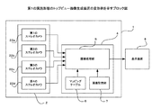
以下、本発明の第1の実施形態を図面に基づいて説明する。図1は、第1の実施形態によるトップビュー画像生成装置1の構成例を示すブロック図である。図1において、2は画像撮影部であり、自車両の周辺を撮影するための第1のカメラ2a、第2のカメラ2b、第3のカメラ2c、第4のカメラ2dにより構成されている。また、3はレーダー(特許請求の範囲の障害物検知部に該当する)であり、自車両の周辺の障害物を検知する。
(First embodiment)
DESCRIPTION OF EXEMPLARY EMBODIMENTS Hereinafter, a first embodiment of the invention will be described with reference to the drawings. FIG. 1 is a block diagram illustrating a configuration example of a top view image generation device 1 according to the first embodiment. In FIG. 1, reference numeral 2 denotes an image photographing unit, which includes a first camera 2a, a second camera 2b, a third camera 2c, and a fourth camera 2d for photographing the periphery of the host vehicle. Reference numeral 3 denotes a radar (corresponding to the obstacle detection unit in the claims), which detects an obstacle around the host vehicle.

図2は、第1の実施形態のトップビュー画像生成装置1による第1のカメラ2a〜第4のカメラ2d及びレーダー3の配置の例を示す図である。図2において、第1のカメラ2aは自車両12の前方に配置され、前方Aの範囲の画像を撮影する。第2のカメラ2bは自車両12の左側方に配置され、左方Bの範囲の画像を撮影する。第3のカメラ2cは自車両12の後方に配置され、後方Cの範囲の画像を撮影する。第4のカメラ2dは自車両12の右側方に配置され、右方Dの範囲の画像を撮影する。   FIG. 2 is a diagram illustrating an example of the arrangement of the first camera 2a to the fourth camera 2d and the radar 3 by the top view image generation device 1 according to the first embodiment. In FIG. 2, the first camera 2 a is disposed in front of the host vehicle 12 and captures an image in the range of the front A. The second camera 2b is disposed on the left side of the host vehicle 12 and captures an image in the range of the left B. The 3rd camera 2c is arrange | positioned at the back of the own vehicle 12, and image | photographs the image of the range of back C. FIG. The 4th camera 2d is arrange | positioned at the right side of the own vehicle 12, and image | photographs the image of the range of the right side D. FIG.

レーダー3は、自車両12の上部中央に設置されており、360°の指向性を持つ赤外線レーダーや超音波レーダーにより構成されている。ここで、赤外線レーダーや超音波レーダーを複数使用して360°の指向性を実現しても良い。また、レーダー3は、自車両12から障害物までの距離、自車両12から障害物の方向、障害物の大きさを検出し、障害物情報として出力する。   The radar 3 is installed in the upper center of the host vehicle 12 and is configured by an infrared radar or an ultrasonic radar having a directivity of 360 °. Here, 360 degree directivity may be realized by using a plurality of infrared radars and ultrasonic radars. The radar 3 detects the distance from the host vehicle 12 to the obstacle, the direction of the obstacle from the host vehicle 12, and the size of the obstacle, and outputs the detected obstacle information.

4は画像生成部であり、画像処理部5、マッピングテーブル6、画像記憶部7により構成されている。画像処理部5では、第1のカメラ2a〜第4のカメラ2dにて撮影された画像を入力し、マッピングテーブル6に記憶されている変換情報に従って、自車両12の周辺を上方から見たときの背景画像を生成する。この状態では、自車両12に設置された第1のカメラ2a〜第4のカメラ2dにて撮影された画像に基づいて背景画像を生成しているので、背景画像に表示されているのは、実際の背景及び背景に含まれる障害物のみとなり、自車両12の画像は表示されない。また、障害物は、背景画像の一部として表示されているので、障害物として認識されていない。   An image generation unit 4 includes an image processing unit 5, a mapping table 6, and an image storage unit 7. In the image processing unit 5, when images taken by the first camera 2 a to the fourth camera 2 d are input and the periphery of the host vehicle 12 is viewed from above according to the conversion information stored in the mapping table 6 Generate a background image. In this state, since the background image is generated based on the images captured by the first camera 2a to the fourth camera 2d installed in the host vehicle 12, what is displayed in the background image is Only the actual background and the obstacle included in the background are present, and the image of the host vehicle 12 is not displayed. Further, since the obstacle is displayed as a part of the background image, it is not recognized as an obstacle.

そこで、画像処理部5は、レーダー3から入力される障害物情報に基づいて、背景画像中の障害物の画像を特定する。具体的には、背景画像中における自車両12の位置、自車両12から障害物までの距離、自車両12から障害物の方向により背景画像中の障害物を特定する。また、画像処理部5は、自車両12から所定の距離内に障害物が存在するか否かを判断する。ここで、所定の距離とは、例えば自車両12に搭載した画像撮影部2の撮影可能範囲やレーダー3により障害物を検知可能な範囲、予め定めた範囲等である。そして、画像処理部5は、自車両12から障害物までの距離が所定の長さより短いか否かを判断する。所定の長さは、例えばトップビュー画像の中央に自車両12を配置したときの自車両12からトップビュー画像の端までの長さを実際の距離に換算したものである。   Therefore, the image processing unit 5 identifies an obstacle image in the background image based on the obstacle information input from the radar 3. Specifically, the obstacle in the background image is specified by the position of the own vehicle 12 in the background image, the distance from the own vehicle 12 to the obstacle, and the direction of the obstacle from the own vehicle 12. Further, the image processing unit 5 determines whether there is an obstacle within a predetermined distance from the host vehicle 12. Here, the predetermined distance is, for example, a shootable range of the image shooting unit 2 mounted on the host vehicle 12, a range in which an obstacle can be detected by the radar 3, a predetermined range, or the like. Then, the image processing unit 5 determines whether or not the distance from the host vehicle 12 to the obstacle is shorter than a predetermined length. The predetermined length is obtained by converting, for example, the length from the host vehicle 12 to the end of the top view image when the host vehicle 12 is arranged in the center of the top view image into an actual distance.

また、画像処理部5は、特定された障害物が所定の大きさ以上であるか否かを判断する。障害物が所定の大きさ以上であると、障害物より先の画像を画像撮影部2にて撮影し難くなる。ここで、所定の大きさ以上の障害物とは、例えば、第2のカメラ2bにより撮影された左側方の画像における障害物の画像の占める割合が所定の値以上の障害物であり、塀や建物の壁等の障害物を指すものである。   Further, the image processing unit 5 determines whether or not the specified obstacle is greater than or equal to a predetermined size. If the obstacle is larger than the predetermined size, it is difficult to take an image ahead of the obstacle by the image photographing unit 2. Here, the obstacle of a predetermined size or more is an obstacle in which the ratio of the obstacle image in the left image taken by the second camera 2b is a predetermined value or more, for example, It refers to an obstacle such as a building wall.

また、画像処理部5は、自車両12を上方から見た画像を示す自車両画像データを画像記憶部7から読み出し、背景画像の所定の位置(例えば背景画像における自車両12が存在する位置)に合成する。   Further, the image processing unit 5 reads out own vehicle image data indicating an image of the host vehicle 12 as viewed from above from the image storage unit 7, and a predetermined position of the background image (for example, a position where the host vehicle 12 exists in the background image). To synthesize.

マッピングテーブル6は、第1のカメラ2a〜第4のカメラ2dにより撮影される画像の画素データと自車両12の周辺を上方の仮想視点から見た背景画像の画素データとの対応関係を記載したテーブルであり、撮影された画像のある画素が背景画像のどの画素に対応するかを示す変換情報を記載している。画像記憶部7は、自車両12を上方から見た画像を示す自車両画像データを記憶しており、必要に応じて画像処理部5により読み出される。   The mapping table 6 describes the correspondence between the pixel data of the images photographed by the first camera 2a to the fourth camera 2d and the pixel data of the background image when the periphery of the host vehicle 12 is viewed from the upper virtual viewpoint. It is a table and describes conversion information indicating which pixel of a background image corresponds to a certain pixel of a photographed image. The image storage unit 7 stores host vehicle image data indicating an image of the host vehicle 12 as viewed from above, and is read out by the image processing unit 5 as necessary.

図3は、第1の実施形態のトップビュー画像生成装置1による合成画像16の例を示す図である。合成画像16は、前述した背景画像に自車両画像を合成した画像であり、その略中央に自車両12の画像を形成し、自車両12の進行方向と略平行に存在している障害物13の画像を自車両12の画像の左側に形成している。ここで、自車両12と障害物13との距離は所定の長さより短くなっている。また、合成画像16では、障害物13により遮られた部分を遮蔽部15の画像として形成しており、自車両12の周辺に存在する道路等の背景を示す背景部14の画像を形成している。   FIG. 3 is a diagram illustrating an example of the composite image 16 by the top view image generation device 1 according to the first embodiment. The composite image 16 is an image obtained by synthesizing the own vehicle image with the background image described above. The image of the own vehicle 12 is formed at the approximate center thereof, and the obstacle 13 exists substantially parallel to the traveling direction of the own vehicle 12. Is formed on the left side of the image of the host vehicle 12. Here, the distance between the host vehicle 12 and the obstacle 13 is shorter than a predetermined length. Further, in the composite image 16, a portion blocked by the obstacle 13 is formed as an image of the shielding portion 15, and an image of the background portion 14 indicating the background of a road or the like existing around the host vehicle 12 is formed. Yes.

画像処理部5では、自車両12の周辺に存在する障害物13と自車両12との距離が所定の長さより短いか否かを判断すると共に、障害物13が所定の大きさ以上であるか否かを判断する。そして、障害物13と自車両12との距離が所定の長さより短く、障害物13が所定の大きさ以上であると判断したときに、自車両12から見た障害物13の方向に応じて、その障害物13をトップビュー画像11の一辺として、前述した合成画像16からトップビュー画像11を切り出して出力する。例えば、自車両12から見た障害物13の方向が左側であるときには、障害物13が左端となるようにトップビュー画像11を切り出し、自車両12から見た障害物13の方向が右側であるときには、障害物13が右端となるようにトップビュー画像11を切り出す。   The image processing unit 5 determines whether or not the distance between the obstacle 13 around the host vehicle 12 and the host vehicle 12 is shorter than a predetermined length, and whether the obstacle 13 is greater than or equal to a predetermined size. Judge whether or not. Then, when it is determined that the distance between the obstacle 13 and the host vehicle 12 is shorter than a predetermined length and the obstacle 13 is greater than or equal to a predetermined size, depending on the direction of the obstacle 13 viewed from the host vehicle 12 Then, with the obstacle 13 as one side of the top view image 11, the top view image 11 is cut out from the composite image 16 and output. For example, when the direction of the obstacle 13 viewed from the host vehicle 12 is the left side, the top view image 11 is cut out so that the obstacle 13 is at the left end, and the direction of the obstacle 13 viewed from the host vehicle 12 is the right side. Sometimes, the top view image 11 is cut out so that the obstacle 13 is at the right end.

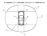
8は表示装置であり、画像処理部5により生成されたトップビュー画像11を表示する。図4は、第1の実施形態のトップビュー画像生成装置1によるトップビュー画像11の例を示す図であり、このトップビュー画像11では、自車両12に近接して存在する障害物13が左端に表示されているので、自車両12が左側に偏って、自車両12の右側のスペースが広く表示されている。ここで、合成画像16からトップビュー画像11を切り出す範囲については、トップビュー画像11を表示する表示装置8のアスペクト比と解像度とに応じて決められるが、合成画像16からトップビュー画像11を切り出す範囲を所定の解像度に固定して、表示装置8の解像度に合わせて画像を拡大又は縮小するようにしても良い。   Reference numeral 8 denotes a display device that displays the top view image 11 generated by the image processing unit 5. FIG. 4 is a diagram illustrating an example of the top view image 11 by the top view image generation device 1 according to the first embodiment. In the top view image 11, the obstacle 13 that exists in the vicinity of the host vehicle 12 is at the left end. Therefore, the host vehicle 12 is biased to the left side, and the space on the right side of the host vehicle 12 is widely displayed. Here, the range in which the top view image 11 is cut out from the composite image 16 is determined according to the aspect ratio and the resolution of the display device 8 that displays the top view image 11, but the top view image 11 is cut out from the composite image 16. The range may be fixed to a predetermined resolution, and the image may be enlarged or reduced in accordance with the resolution of the display device 8.

次に、第1の実施形態によるトップビュー画像生成装置1の動作及びトップビュー画像表示方法について説明する。図5は、第1の実施形態によるトップビュー画像生成装置1の動作及びトップビュー画像表示方法を示すフローチャートである。図5において、自車両12に設置された第1のカメラ2a〜第4のカメラ2dは、常に自車両12の周辺を撮影している。同様に、自車両12に設置されたレーダー3は、常に自車両12の周辺の障害物13を検知している。   Next, the operation of the top view image generation device 1 and the top view image display method according to the first embodiment will be described. FIG. 5 is a flowchart showing the operation of the top view image generation device 1 and the top view image display method according to the first embodiment. In FIG. 5, the first camera 2 a to the fourth camera 2 d installed in the host vehicle 12 always shoots the periphery of the host vehicle 12. Similarly, the radar 3 installed in the host vehicle 12 always detects an obstacle 13 around the host vehicle 12.

ここで、画像処理部5では、レーダー3からの障害物情報に基づいて、自車両12から所定の距離内に障害物13が存在するか否かを調べる(ステップS1)。画像処理部5にて、自車両12から所定の距離内に障害物13がないと判断された場合には(ステップS1にてNO)、画像処理部5では、第1のカメラ2a〜第4のカメラ2dにて撮影された画像を入力し、マッピングテーブル6に記憶されている変換情報に従って、背景画像を生成する。そして、画像記憶部7から自車両画像データを読み出して背景画像に合成することによって合成画像16を生成し、その合成画像16から自車両12を中央に配置したトップビュー画像11を切り出す(ステップS2)。   Here, the image processing unit 5 checks whether or not the obstacle 13 exists within a predetermined distance from the host vehicle 12 based on the obstacle information from the radar 3 (step S1). When the image processing unit 5 determines that there is no obstacle 13 within a predetermined distance from the host vehicle 12 (NO in step S1), the image processing unit 5 uses the first camera 2a to the fourth camera. An image captured by the camera 2d is input, and a background image is generated according to the conversion information stored in the mapping table 6. Then, the host vehicle image data is read from the image storage unit 7 and synthesized with the background image to generate a synthesized image 16, and the top view image 11 in which the host vehicle 12 is arranged at the center is cut out from the synthesized image 16 (step S <b> 2). ).

一方、画像処理部5にて、自車両12から所定の距離内に障害物13があると判断された場合には(ステップS1にてYES)、画像処理部5では、自車両12と自車両12の周辺に存在する障害物13との距離が所定の長さよりも短く、且つ、障害物13が所定の大きさ以上であるか否かを調べる(ステップS3)。   On the other hand, when the image processing unit 5 determines that there is an obstacle 13 within a predetermined distance from the host vehicle 12 (YES in step S1), the image processing unit 5 uses the host vehicle 12 and the host vehicle. It is checked whether the distance from the obstacle 13 around 12 is shorter than a predetermined length and the obstacle 13 is not less than a predetermined size (step S3).

自車両12と障害物13との距離が所定の長さ以上であると画像処理部5にて判断された場合、又は、障害物13が所定の大きさ以上ではないと画像処理部5にて判断された場合には(ステップS3にてNO)、画像処理部5では、第1のカメラ2a〜第4のカメラ2dにて撮影された画像を入力し、マッピングテーブル6に記憶されている変換情報に従って、背景画像を生成する。そして、画像記憶部7から自車両画像データを読み出して自車両12を背景画像に合成した合成画像16を生成し、自車両12を中央に配置したトップビュー画像11を合成画像16から切り出す(ステップS2)。   When the image processing unit 5 determines that the distance between the host vehicle 12 and the obstacle 13 is equal to or greater than a predetermined length, or when the obstacle 13 is not equal to or greater than the predetermined size, the image processing unit 5 If it is determined (NO in step S3), the image processing unit 5 inputs the images photographed by the first camera 2a to the fourth camera 2d, and the conversion stored in the mapping table 6 A background image is generated according to the information. Then, the host vehicle image data is read from the image storage unit 7 to generate a composite image 16 in which the host vehicle 12 is combined with the background image, and the top view image 11 with the host vehicle 12 placed at the center is cut out from the composite image 16 (step) S2).

一方、自車両12と障害物13との距離が所定の長さより短く、且つ、障害物13が所定の大きさ以上であると画像処理部5にて判断された場合には(ステップS3にてYES)、画像処理部5では、第1のカメラ2a〜第4のカメラ2dにて撮影された画像を入力し、マッピングテーブル6に記憶されている変換情報に従って、背景画像を生成する。そして、画像記憶部7から自車両画像データを読み出して自車両12を背景画像に合成した合成画像16を生成する。更に、画像処理部5では、自車両12との距離が所定の長さよりも短い障害物13を背景画像中で特定すると共に、自車両12から見た障害物13の方向に応じて、特定された障害物13を一辺とするトップビュー画像11を合成画像16から切り出す(ステップS4)。   On the other hand, when the image processing unit 5 determines that the distance between the host vehicle 12 and the obstacle 13 is shorter than a predetermined length and the obstacle 13 is not less than a predetermined size (in step S3). YES), the image processing unit 5 inputs images taken by the first camera 2a to the fourth camera 2d, and generates a background image according to the conversion information stored in the mapping table 6. And the own vehicle image data is read from the image memory | storage part 7, and the synthetic | combination image 16 which synthesize | combined the own vehicle 12 with the background image is produced | generated. Further, the image processing unit 5 specifies an obstacle 13 whose distance from the host vehicle 12 is shorter than a predetermined length in the background image, and is specified according to the direction of the obstacle 13 viewed from the host vehicle 12. The top view image 11 having the obstruction 13 as one side is cut out from the composite image 16 (step S4).

ここで、特定された障害物13が自車両12の左側にあるときには、特定された障害物13がトップビュー画像11の左端になるようにトップビュー画像11を切り出し、特定された障害物13が自車両12の右側にあるときには、特定された障害物13がトップビュー画像11の右端になるようにトップビュー画像11を切り出す。例えば、図3に示すような合成画像16では、特定された障害物13が自車両12の左側にあるため、特定された障害物13が左端になるようにトップビュー画像11が切り出される。   Here, when the specified obstacle 13 is on the left side of the host vehicle 12, the top view image 11 is cut out so that the specified obstacle 13 becomes the left end of the top view image 11, and the specified obstacle 13 is When the vehicle is on the right side of the host vehicle 12, the top view image 11 is cut out so that the specified obstacle 13 becomes the right end of the top view image 11. For example, in the composite image 16 as shown in FIG. 3, since the identified obstacle 13 is on the left side of the host vehicle 12, the top view image 11 is cut out so that the identified obstacle 13 is at the left end.

ステップS2又はステップS4の処理によりトップビュー画像11が生成されると、画像処理部5では、切り出されたトップビュー画像11を表示装置8に表示する(ステップS6)。そして、画像処理部5では、運転者等が図示しない操作部によりトップビュー画像11の表示を解除したか否かを調べる(ステップS6)。トップビュー画像11の表示が解除されなかった場合には(ステップS6にてNO)、ステップS1の処理に戻る。一方、トップビュー画像11の表示が解除された場合には(ステップS6にてYES)、処理を終了する。   When the top view image 11 is generated by the process of step S2 or step S4, the image processing unit 5 displays the clipped top view image 11 on the display device 8 (step S6). Then, the image processing unit 5 checks whether or not the driver or the like has canceled the display of the top view image 11 using an operation unit (not shown) (step S6). If display of top view image 11 has not been canceled (NO in step S6), the process returns to step S1. On the other hand, when display of top view image 11 is canceled (YES in step S6), the process ends.

以上詳しく説明したように、第1の実施形態では、自車両12及び自車両12の周辺を上方の仮想視点から見たトップビュー画像11を生成する際に、自車両12と自車両12の片側に存在する障害物13との距離が所定の長さより短く、且つ、障害物13が所定の大きさ以上である場合には、その障害物13がトップビュー画像11の一辺となるように合成画像16からトップビュー画像11を切り出している。これにより、障害物13によって遮られる遮蔽部15がトップビュー画像11中に表示されなくなり、遮蔽部15が存在しない側の画像を広く表示することができるので、トップビュー画像11の表示領域を有効に活用することができ、運転者にとって有効な情報を多く含むトップビュー画像11を表示することができる。   As described above in detail, in the first embodiment, when generating the top view image 11 in which the host vehicle 12 and the periphery of the host vehicle 12 are viewed from the upper virtual viewpoint, one side of the host vehicle 12 and the host vehicle 12 is generated. When the obstacle 13 is shorter than a predetermined length and the obstacle 13 is not less than a predetermined size, the composite image is formed so that the obstacle 13 is one side of the top view image 11. The top view image 11 is cut out from 16. As a result, the shielding part 15 that is blocked by the obstacle 13 is not displayed in the top view image 11, and the image on the side where the shielding part 15 is not present can be displayed widely, so that the display area of the top view image 11 is effective. The top view image 11 including a lot of information useful for the driver can be displayed.

(第2の実施形態)
以下、本発明の第2の実施形態を図面に基づいて説明する。なお、第2の実施形態によるトップビュー画像生成装置1の構成については、図1と同様であるから説明を省略する。ただし、表示装置8に表示されるトップビュー画像11は図7、図9、及び図11に示すような画像であり、画像処理部5は後述する処理を行う点で第1の実施形態と相違する。
(Second Embodiment)
Hereinafter, a second embodiment of the present invention will be described with reference to the drawings. The configuration of the top view image generation device 1 according to the second embodiment is the same as that in FIG. However, the top view image 11 displayed on the display device 8 is an image as shown in FIGS. 7, 9, and 11, and the image processing unit 5 is different from the first embodiment in that the processing described later is performed. To do.

画像処理部5では、第1のカメラ2a〜第4のカメラ2dにて撮影された画像を入力し、マッピングテーブル6に記憶されている変換情報に従って、自車両12の周辺を上方の仮想視点から見たときの背景画像を生成する。また、画像処理部5では、レーダー3から入力される障害物情報に基づいて、背景画像中の障害物13の画像を特定する。具体的には、背景画像中における自車両12の位置、自車両12から障害物13までの距離、自車両12から障害物13の方向により背景画像中の障害物13を特定する。   In the image processing unit 5, images taken by the first camera 2 a to the fourth camera 2 d are input, and the periphery of the host vehicle 12 is viewed from the upper virtual viewpoint according to the conversion information stored in the mapping table 6. Generate a background image when viewed. Further, the image processing unit 5 specifies an image of the obstacle 13 in the background image based on the obstacle information input from the radar 3. Specifically, the obstacle 13 in the background image is specified by the position of the own vehicle 12 in the background image, the distance from the own vehicle 12 to the obstacle 13, and the direction from the own vehicle 12 to the obstacle 13.

そして、画像処理部5は、自車両12から所定の距離内に、且つ、自車両12の両側に所定の大きさ以上の障害物13が存在するか否かを判断する。ここで、所定の距離とは、例えば自車両12に搭載した画像撮影部2の撮影可能範囲やレーダー3により障害物13を検知可能な範囲、予め定めた範囲等である。   Then, the image processing unit 5 determines whether or not an obstacle 13 having a predetermined size or more exists within a predetermined distance from the host vehicle 12 and on both sides of the host vehicle 12. Here, the predetermined distance is, for example, a shootable range of the image shooting unit 2 mounted on the host vehicle 12, a range where the obstacle 13 can be detected by the radar 3, a predetermined range, or the like.

また、画像処理部5は、特定された障害物13が所定の大きさ以上であるか否かを判断する。障害物13が所定の大きさ以上であると、障害物13より先の画像を画像撮影部2にて撮影し難くなる。また、画像処理部5は、自車両12を上方から見た画像を示す自車両画像データを画像記憶部7から読み出し、背景画像の所定の位置(例えば背景画像における自車両12が存在する位置)に合成する。   Further, the image processing unit 5 determines whether or not the specified obstacle 13 is greater than or equal to a predetermined size. If the obstacle 13 is larger than a predetermined size, it is difficult to take an image ahead of the obstacle 13 by the image photographing unit 2. Further, the image processing unit 5 reads out own vehicle image data indicating an image of the host vehicle 12 as viewed from above from the image storage unit 7, and a predetermined position of the background image (for example, a position where the host vehicle 12 exists in the background image). To synthesize.

また、画像処理部5では、自車両12から自車両12の片側の障害物13までの距離と自車両12から自車両12のもう一方の片側の障害物13までの距離との合計が所定の長さの二倍よりも短いか否かを判断する。所定の長さは、例えば縮尺を変更していないトップビュー画像11の中央に自車両12を配置したときの自車両12からトップビュー画像11の端までの長さを実際の距離に換算したものである。ここで、自車両12から自車両12の片側の障害物13までの距離と自車両12から自車両12のもう一方の片側の障害物13までの距離との合計が所定の長さの二倍よりも短い場合(例えば図6及び図8)と、自車両12から自車両12の片側の障害物13までの距離と自車両12から自車両12のもう一方の片側の障害物13までの距離との合計が所定の長さの二倍よりも長い場合(図10)とがある。   Further, in the image processing unit 5, the sum of the distance from the own vehicle 12 to the obstacle 13 on one side of the own vehicle 12 and the distance from the own vehicle 12 to the other obstacle 13 on the other side of the own vehicle 12 is a predetermined value. It is determined whether or not it is shorter than twice the length. The predetermined length is obtained by converting the length from the own vehicle 12 to the end of the top view image 11 when the own vehicle 12 is arranged at the center of the top view image 11 whose scale is not changed, for example, into an actual distance. It is. Here, the sum of the distance from the host vehicle 12 to the obstacle 13 on one side of the host vehicle 12 and the distance from the host vehicle 12 to the obstacle 13 on the other side of the host vehicle 12 is twice the predetermined length. When the distance is shorter (for example, FIGS. 6 and 8), the distance from the own vehicle 12 to the obstacle 13 on one side of the own vehicle 12 and the distance from the own vehicle 12 to the obstacle 13 on the other side of the own vehicle 12 Is longer than twice the predetermined length (FIG. 10).

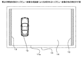
図6は、第2の実施形態のトップビュー画像生成装置1による合成画像16の例を示す図であり、自車両12から自車両12の片側の障害物13までの距離と自車両12から自車両12のもう一方の片側の障害物13までの距離との合計が所定の長さの二倍よりも短い場合の合成画像16の例を示す図である。また、図6に示す合成画像16は、自車両12から自車両12の両側に存在する障害物13までの距離が何れも所定の長さより短い場合の画像である。また、図7は、第2の実施形態のトップビュー画像生成装置1によって図6に示す合成画像16より生成されるトップビュー画像11の例を示す図である。   FIG. 6 is a diagram illustrating an example of the composite image 16 by the top view image generation device 1 according to the second embodiment. The distance from the own vehicle 12 to the obstacle 13 on one side of the own vehicle 12 and the own vehicle 12 from the own vehicle 12 are illustrated. It is a figure which shows the example of the synthetic | combination image 16 in case the sum total with the distance to the obstruction 13 of the other one side of the vehicle 12 is shorter than twice predetermined length. A composite image 16 shown in FIG. 6 is an image when the distance from the own vehicle 12 to the obstacle 13 existing on both sides of the own vehicle 12 is shorter than a predetermined length. FIG. 7 is a diagram illustrating an example of the top view image 11 generated from the composite image 16 illustrated in FIG. 6 by the top view image generation device 1 according to the second embodiment.

図6において、合成画像16は、背景画像に自車両画像を合成した画像であり、その略中央に自車両12の画像を形成し、自車両12の進行方向と略平行に存在している障害物13の画像を自車両12の画像の両側に形成している。また、合成画像16では、障害物13により遮られた部分を遮蔽部15の画像として形成しており、自車両12の周辺に存在する道路等の背景を示す背景部14の画像を形成している。   In FIG. 6, a synthesized image 16 is an image obtained by synthesizing the own vehicle image with the background image, and forms an image of the own vehicle 12 in the approximate center thereof, and is a fault that exists substantially parallel to the traveling direction of the own vehicle 12. The image of the object 13 is formed on both sides of the image of the host vehicle 12. Further, in the composite image 16, a portion blocked by the obstacle 13 is formed as an image of the shielding portion 15, and an image of the background portion 14 indicating the background of a road or the like existing around the host vehicle 12 is formed. Yes.

画像処理部5では、自車両12から所定の距離内に、且つ、自車両12の両側に障害物13が存在するか否かを判断すると共に、その障害物13が所定の大きさ以上であるか否かを調べる。そして、自車両12から所定の距離内に、且つ、自車両12の両側に所定の大きさ以上の障害物13が存在すると判断したときには、画像処理部5では、自車両12から自車両12の片側の障害物13までの距離と自車両12から自車両12のもう一方の片側の障害物13までの距離との合計が所定の長さの二倍よりも短いか否かを判断する。   The image processing unit 5 determines whether or not there is an obstacle 13 within a predetermined distance from the host vehicle 12 and on both sides of the host vehicle 12, and the obstacle 13 is greater than or equal to a predetermined size. Check whether or not. When it is determined that an obstacle 13 having a predetermined size or more exists within a predetermined distance from the own vehicle 12 and on both sides of the own vehicle 12, the image processing unit 5 It is determined whether or not the sum of the distance to the obstacle 13 on one side and the distance from the host vehicle 12 to the obstacle 13 on the other side of the host vehicle 12 is shorter than twice the predetermined length.

ここで、自車両12から自車両12の片側の障害物13までの距離と自車両12から自車両12のもう一方の片側の障害物13までの距離との合計が所定の長さの二倍よりも短い場合には、画像処理部5は、自車両12の左側に存在している障害物13の画像を左辺とし、自車両12の右側に存在している障害物13の画像を右辺として、前述した合成画像16からトップビュー予備画像11aを切り出して出力する。このとき、自車両12の左側に存在している障害物13と自車両12の右側に存在している障害物13との距離をトップビュー予備画像11aの横方向の長さとすると、表示装置8のアスペクト比に合わせてトップビュー予備画像11aの縦方向の長さが決まる。しかしながら、図6のように、自車両12の両側に存在する障害物13の距離が近付きすぎると、自車両12の画像がトップビュー予備画像11aに納まらなくなってしまうので、自車両12がトップビュー予備画像11aに納まるように縦方向の長さを伸ばしてトップビュー予備画像11aを切り出す。   Here, the sum of the distance from the host vehicle 12 to the obstacle 13 on one side of the host vehicle 12 and the distance from the host vehicle 12 to the obstacle 13 on the other side of the host vehicle 12 is twice the predetermined length. The image processing unit 5 uses the image of the obstacle 13 present on the left side of the host vehicle 12 as the left side and the image of the obstacle 13 present on the right side of the host vehicle 12 as the right side. The top-view preliminary image 11a is cut out from the composite image 16 and output. At this time, if the distance between the obstacle 13 existing on the left side of the host vehicle 12 and the obstacle 13 existing on the right side of the host vehicle 12 is the horizontal length of the top view preliminary image 11a, the display device 8 The vertical length of the top-view preliminary image 11a is determined in accordance with the aspect ratio. However, as shown in FIG. 6, if the distance between the obstacles 13 existing on both sides of the host vehicle 12 is too close, the image of the host vehicle 12 will not fit in the top view preliminary image 11a. The top view preliminary image 11a is cut out by extending the length in the vertical direction so as to fit in the preliminary image 11a.

そして、画像処理部5は、トップビュー予備画像11aをトップビュー画像11の表示領域に貼り付けてトップビュー画像11を生成する。このとき、画像処理部5は、図7に示すように、トップビュー予備画像11aの左辺とトップビュー画像11の表示領域の左辺との間、及び、トップビュー予備画像11aの右辺とトップビュー画像11の表示領域の右辺との間に存在する余白部17が最も少なくなり、且つ、自車両12の画像がトップビュー画像11に納まるように、トップビュー予備画像11aを拡大している。ここで、余白部17が最も少なくなることとは、換言すると、トップビュー予備画像11aの左右の辺とトップビュー画像11の表示領域の左右の辺との間隔が最も小さくなることを指す。ここで、図7の例では、トップビュー画像11の表示領域の左辺からトップビュー予備画像11aの左辺までの距離とトップビュー画像11の表示領域の右辺からトップビュー予備画像11aの右辺までの距離とが等距離となるようにトップビュー予備画像11aを貼り付けているが、必ずしも等距離とする必要はない。   Then, the image processing unit 5 generates the top view image 11 by pasting the top view preliminary image 11 a on the display area of the top view image 11. At this time, as shown in FIG. 7, the image processing unit 5 is located between the left side of the top view preliminary image 11a and the left side of the display area of the top view image 11, and the right side and top view image of the top view preliminary image 11a. The top view preliminary image 11a is enlarged so that the margin 17 existing between the right side of the display area 11 is minimized and the image of the host vehicle 12 is accommodated in the top view image 11. Here, the smallest margin portion 17 means that the distance between the left and right sides of the top view preliminary image 11a and the left and right sides of the display area of the top view image 11 is the smallest. In the example of FIG. 7, the distance from the left side of the display area of the top view image 11 to the left side of the top view preliminary image 11a and the distance from the right side of the display area of the top view image 11 to the right side of the top view preliminary image 11a. Although the top view preliminary image 11a is pasted so that the distances are equal to each other, they are not necessarily equal distances.

なお、図6の例において、自車両12の左側に存在している障害物13の画像を左辺とし、自車両12の右側に存在している障害物13の画像を右辺として、合成画像16からトップビュー予備画像11aを切り出しているが、これに限定されない。例えば、自車両12の画像がトップビュー画像11に納まり、余白部17が最小となるように、表示装置8と同じアスペクト比でトップビュー画像11を直接切り出すようにしても良い。   In the example of FIG. 6, from the composite image 16, the image of the obstacle 13 present on the left side of the host vehicle 12 is the left side, and the image of the obstacle 13 present on the right side of the host vehicle 12 is the right side. Although the top view preliminary image 11a is cut out, the present invention is not limited to this. For example, the top view image 11 may be directly cut out with the same aspect ratio as that of the display device 8 so that the image of the host vehicle 12 fits in the top view image 11 and the margin portion 17 is minimized.

また、トップビュー画像11の表示領域に自車両12の画像が納まれば、トップビュー画像11の表示領域の左辺からトップビュー予備画像11aの左辺までの距離及びトップビュー画像11の表示領域の右辺からトップビュー予備画像11aの右辺までの距離が0となるようにトップビュー画像11を生成しても良く、その場合、余白部17は存在しない。また、トップビュー画像11に自車両12の画像が納まるという条件については、例えば自車両12の画像の前方や後方にある程度のスペースを確保するようにしても良いし、自車両12の前方や後方に全くスペースを設けないようにしても良い。   If the image of the host vehicle 12 is stored in the display area of the top view image 11, the distance from the left side of the display area of the top view image 11 to the left side of the top view preliminary image 11a and the right side of the display area of the top view image 11 The top view image 11 may be generated such that the distance from the right side of the top view preliminary image 11a to 0 is zero, and in this case, the blank portion 17 does not exist. As for the condition that the image of the host vehicle 12 fits in the top view image 11, for example, a certain amount of space may be secured in front of or behind the image of the host vehicle 12, or the front or rear of the host vehicle 12. There may be no space at all.

図8は、第2の実施形態のトップビュー画像生成装置1による合成画像16の他の例を示す図であり、自車両12から自車両12の片側の障害物13までの距離と自車両12から自車両12のもう一方の片側の障害物13までの距離との合計が所定の長さの二倍よりも短い場合の合成画像16の例を示す図である。また、図8に示す合成画像16は、自車両12から自車両12の右側に存在する障害物13までの距離が所定の長さよりも長い場合の画像である。また、図9は、第2の実施形態のトップビュー画像生成装置1によって図8に示す合成画像16より生成されるトップビュー画像11の例を示す図である。   FIG. 8 is a diagram illustrating another example of the composite image 16 by the top view image generation device 1 according to the second embodiment. The distance from the host vehicle 12 to the obstacle 13 on one side of the host vehicle 12 and the host vehicle 12 are also illustrated. It is a figure which shows the example of the synthetic | combination image 16 in case the sum total with the distance to the obstacle 13 of the other side of the own vehicle 12 is shorter than twice predetermined length. 8 is an image in the case where the distance from the own vehicle 12 to the obstacle 13 existing on the right side of the own vehicle 12 is longer than a predetermined length. FIG. 9 is a diagram illustrating an example of the top view image 11 generated from the composite image 16 illustrated in FIG. 8 by the top view image generation device 1 according to the second embodiment.

画像処理部5では、自車両12から所定の距離内に、且つ、自車両12の両側に障害物13が存在するか否かを判断すると共に、その障害物13が所定の大きさ以上であるか否かを調べる。そして、自車両12から所定の距離内に、且つ、自車両12の両側に所定の大きさ以上の障害物13が存在すると判断したときには、画像処理部5では、自車両12から自車両12の片側の障害物13までの距離と自車両12から自車両12のもう一方の片側の障害物13までの距離との合計が所定の長さの二倍よりも短いか否かを判断する。   The image processing unit 5 determines whether or not there is an obstacle 13 within a predetermined distance from the host vehicle 12 and on both sides of the host vehicle 12, and the obstacle 13 is greater than or equal to a predetermined size. Check whether or not. When it is determined that an obstacle 13 having a predetermined size or more exists within a predetermined distance from the own vehicle 12 and on both sides of the own vehicle 12, the image processing unit 5 It is determined whether or not the sum of the distance to the obstacle 13 on one side and the distance from the host vehicle 12 to the obstacle 13 on the other side of the host vehicle 12 is shorter than twice the predetermined length.

ここで、自車両12から自車両12の片側の障害物13までの距離と自車両12から自車両12のもう一方の片側の障害物13までの距離との合計が所定の長さの二倍よりも短い場合には、画像処理部5は、自車両12の左側に存在している障害物13の画像を左辺とし、自車両12の右側に存在している障害物13の画像を右辺として、前述した合成画像16からトップビュー予備画像11aを切り出して出力する。このとき、自車両12の左側に存在している障害物13と自車両12の右側に存在している障害物13との距離をトップビュー予備画像11aの横方向の長さとすると、表示装置8のアスペクト比に合わせてトップビュー予備画像11aの縦方向の長さが決まる。図8の例では、自車両12の画像がトップビュー予備画像11aに納まるので、トップビュー予備画像11aを表示装置8のアスペクト比に合わせて切り出す。   Here, the sum of the distance from the host vehicle 12 to the obstacle 13 on one side of the host vehicle 12 and the distance from the host vehicle 12 to the obstacle 13 on the other side of the host vehicle 12 is twice the predetermined length. The image processing unit 5 uses the image of the obstacle 13 present on the left side of the host vehicle 12 as the left side and the image of the obstacle 13 present on the right side of the host vehicle 12 as the right side. The top-view preliminary image 11a is cut out from the composite image 16 and output. At this time, if the distance between the obstacle 13 existing on the left side of the host vehicle 12 and the obstacle 13 existing on the right side of the host vehicle 12 is the horizontal length of the top view preliminary image 11a, the display device 8 The vertical length of the top-view preliminary image 11a is determined in accordance with the aspect ratio. In the example of FIG. 8, since the image of the host vehicle 12 is stored in the top view preliminary image 11 a, the top view preliminary image 11 a is cut out in accordance with the aspect ratio of the display device 8.

そして、画像処理部5は、トップビュー予備画像11aを拡大してトップビュー画像11の表示領域に貼り付けてトップビュー画像11を生成する。このように、表示装置8のアスペクト比に合わせてトップビュー画像11よりも小さいトップビュー予備画像11aを切り出しているので、トップビュー画像11の表示領域の左辺からトップビュー予備画像11aの左辺までの距離及びトップビュー画像11の表示領域の右辺からトップビュー予備画像11aの右辺までの距離が0となるようにトップビュー予備画像11aを拡大することができる。   Then, the image processing unit 5 enlarges the top view preliminary image 11 a and pastes it on the display area of the top view image 11 to generate the top view image 11. Thus, since the top view preliminary image 11a smaller than the top view image 11 is cut out in accordance with the aspect ratio of the display device 8, from the left side of the display area of the top view image 11 to the left side of the top view preliminary image 11a. The top view preliminary image 11a can be enlarged so that the distance and the distance from the right side of the display area of the top view image 11 to the right side of the top view preliminary image 11a become zero.

また、図10は、第2の実施形態のトップビュー画像生成装置1による合成画像16の更に他の例を示す図であり、自車両12から自車両12の片側の障害物13までの距離と自車両12から自車両12のもう一方の片側の障害物13までの距離との合計が所定の長さの二倍よりも長い場合の合成画像16の例である。図11は、第2の実施形態のトップビュー画像生成装置1によって図10に示す合成画像16より生成されるトップビュー画像11の例を示す図である。   FIG. 10 is a diagram showing still another example of the composite image 16 by the top view image generation device 1 according to the second embodiment, and the distance from the own vehicle 12 to the obstacle 13 on one side of the own vehicle 12. It is an example of the composite image 16 when the sum of the distance from the host vehicle 12 to the obstacle 13 on the other side of the host vehicle 12 is longer than twice the predetermined length. FIG. 11 is a diagram illustrating an example of the top view image 11 generated from the composite image 16 illustrated in FIG. 10 by the top view image generation device 1 according to the second embodiment.

図10において、合成画像16は、背景画像に自車両画像を合成した画像であり、その略中央に自車両12の画像を形成し、自車両12の進行方向と略平行に存在している障害物13の画像を自車両12の画像の両側に形成している。また、合成画像16では、障害物13により遮られた部分を遮蔽部15の画像として形成しており、自車両12の周辺に存在する道路等の背景を示す背景部14の画像を形成している。   In FIG. 10, a composite image 16 is an image in which the host vehicle image is combined with the background image, and an image of the host vehicle 12 is formed in the approximate center of the background image, and the fault exists substantially parallel to the traveling direction of the host vehicle 12. The image of the object 13 is formed on both sides of the image of the host vehicle 12. Further, in the composite image 16, a portion blocked by the obstacle 13 is formed as an image of the shielding portion 15, and an image of the background portion 14 indicating the background of a road or the like existing around the host vehicle 12 is formed. Yes.

画像処理部5では、自車両12から所定の距離内に、且つ、自車両12の両側に障害物13が存在するか否かを判断すると共に、その障害物13が所定の大きさ以上であるか否かを調べる。そして、自車両12から所定の距離内に、且つ、自車両12の両側に所定の大きさ以上の障害物13が存在すると判断したときには、画像処理部5では、自車両12から自車両12の片側の障害物13までの距離と自車両12から自車両12のもう一方の片側の障害物13までの距離との合計が所定の長さの二倍よりも短いか否かを判断する。   The image processing unit 5 determines whether or not there is an obstacle 13 within a predetermined distance from the host vehicle 12 and on both sides of the host vehicle 12, and the obstacle 13 is greater than or equal to a predetermined size. Check whether or not. When it is determined that an obstacle 13 having a predetermined size or more exists within a predetermined distance from the own vehicle 12 and on both sides of the own vehicle 12, the image processing unit 5 It is determined whether or not the sum of the distance to the obstacle 13 on one side and the distance from the host vehicle 12 to the obstacle 13 on the other side of the host vehicle 12 is shorter than twice the predetermined length.

ここで、自車両12から自車両12の片側の障害物13までの距離と自車両12から自車両12のもう一方の片側の障害物13までの距離との合計が所定の長さの二倍よりも長い場合には、画像処理部5は、自車両12の左側に存在している障害物13の画像を左辺とし、自車両12の右側に存在している障害物13の画像を右辺として、前述した合成画像16からトップビュー予備画像11aを切り出して出力する。このとき、自車両12の左側に存在している障害物13と自車両12の右側に存在している障害物13との距離をトップビュー予備画像11aの横方向の長さとすると、表示装置8のアスペクト比に合わせてトップビュー予備画像11aの縦方向の長さが決まる。図10の例では、自車両12の画像がトップビュー予備画像11aに納まるので、トップビュー予備画像11aを表示装置8のアスペクト比に合わせて切り出す。   Here, the sum of the distance from the host vehicle 12 to the obstacle 13 on one side of the host vehicle 12 and the distance from the host vehicle 12 to the obstacle 13 on the other side of the host vehicle 12 is twice the predetermined length. The image of the obstacle 13 existing on the left side of the host vehicle 12 is the left side, and the image of the obstacle 13 existing on the right side of the host vehicle 12 is the right side. The top-view preliminary image 11a is cut out from the composite image 16 and output. At this time, if the distance between the obstacle 13 existing on the left side of the host vehicle 12 and the obstacle 13 existing on the right side of the host vehicle 12 is the horizontal length of the top view preliminary image 11a, the display device 8 The vertical length of the top-view preliminary image 11a is determined in accordance with the aspect ratio. In the example of FIG. 10, since the image of the host vehicle 12 is stored in the top view preliminary image 11 a, the top view preliminary image 11 a is cut out in accordance with the aspect ratio of the display device 8.

そして、画像処理部5は、トップビュー予備画像11aを縮小してトップビュー画像11の表示領域に貼り付けてトップビュー画像11を生成する。このとき、自車両12から自車両12の片側の障害物13までの距離と自車両12から自車両12のもう一方の片側の障害物13までの距離との合計が所定の長さの二倍よりも長いので、トップビュー予備画像11aは、自車両12の両側に存在する障害物13がトップビュー画像11の両端となるまで縮小されてトップビュー画像11の表示領域に貼り付けられる。この場合は、トップビュー画像11の表示領域の左辺からトップビュー予備画像11aの左辺までの距離及びトップビュー画像11の表示領域の右辺からトップビュー予備画像11aの右辺までの距離は0となり、余白部17は存在しなくなる。   Then, the image processing unit 5 generates the top view image 11 by reducing the top view preliminary image 11 a and pasting it on the display area of the top view image 11. At this time, the sum of the distance from the host vehicle 12 to the obstacle 13 on one side of the host vehicle 12 and the distance from the host vehicle 12 to the obstacle 13 on the other side of the host vehicle 12 is twice the predetermined length. Therefore, the top view preliminary image 11 a is reduced until the obstacle 13 existing on both sides of the host vehicle 12 reaches both ends of the top view image 11 and is pasted on the display area of the top view image 11. In this case, the distance from the left side of the display area of the top view image 11 to the left side of the top view preliminary image 11a and the distance from the right side of the display area of the top view image 11 to the right side of the top view preliminary image 11a are 0, and the margin The part 17 does not exist.

このように、表示装置8のアスペクト比に合わせてトップビュー画像11よりも大きいトップビュー予備画像11aを切り出しているので、トップビュー画像11の表示領域の左辺からトップビュー予備画像11aの左辺までの距離及びトップビュー画像11の表示領域の右辺からトップビュー予備画像11aの右辺までの距離が0となるようにトップビュー予備画像11aを縮小することができる。   As described above, the top view preliminary image 11a larger than the top view image 11 is cut out in accordance with the aspect ratio of the display device 8, and therefore, the left side of the display area of the top view image 11 to the left side of the top view preliminary image 11a. The top view preliminary image 11a can be reduced so that the distance and the distance from the right side of the display area of the top view image 11 to the right side of the top view preliminary image 11a become zero.

次に、第2の実施形態によるトップビュー画像生成装置1の動作及びトップビュー画像表示方法について説明する。図12は、第2の実施形態によるトップビュー画像生成装置1の動作及びトップビュー画像表示方法を示すフローチャートである。図12において、自車両12に設置された第1のカメラ2a〜第4のカメラ2dは、常に自車両12の周辺を撮影している。同様に、自車両12に設置されたレーダー3は、常に自車両12の周辺の障害物13を検知している。   Next, the operation of the top view image generation apparatus 1 and the top view image display method according to the second embodiment will be described. FIG. 12 is a flowchart illustrating the operation of the top view image generation apparatus 1 and the top view image display method according to the second embodiment. In FIG. 12, the first camera 2 a to the fourth camera 2 d installed in the host vehicle 12 always shoots the periphery of the host vehicle 12. Similarly, the radar 3 installed in the host vehicle 12 always detects an obstacle 13 around the host vehicle 12.

ここで、画像処理部5では、レーダー3からの障害物情報に基づいて、自車両12から所定の距離内に、且つ、自車両12の両側に所定の大きさ以上の障害物13が存在するか否かを調べる(ステップS11)。自車両12から所定の距離内に、且つ、自車両12の両側に所定の大きさ以上の障害物13が存在しないと画像処理部5にて判断された場合には(ステップS11にてNO)、画像処理部5では、第1のカメラ2a〜第4のカメラ2dにて撮影された画像を入力し、マッピングテーブル6に記憶されている変換情報に従って、背景画像を生成する。そして、画像記憶部7から自車両画像データを読み出して背景画像に合成することによって合成画像16を生成し、その合成画像16から自車両12を中央に配置したトップビュー画像11を切り出す(ステップS12)。   Here, in the image processing unit 5, an obstacle 13 having a predetermined size or more exists within a predetermined distance from the own vehicle 12 and on both sides of the own vehicle 12 based on the obstacle information from the radar 3. It is checked whether or not (step S11). When the image processing unit 5 determines that there is no obstacle 13 having a predetermined size or more within a predetermined distance from the host vehicle 12 and on both sides of the host vehicle 12 (NO in step S11). In the image processing unit 5, images taken by the first camera 2 a to the fourth camera 2 d are input, and a background image is generated according to the conversion information stored in the mapping table 6. Then, the host vehicle image data is read from the image storage unit 7 and synthesized with the background image to generate a synthesized image 16, and the top view image 11 with the host vehicle 12 placed at the center is cut out from the synthesized image 16 (step S 12). ).

一方、自車両12から所定の距離内に、且つ、自車両12の両側に所定の大きさ以上の障害物13が存在すると画像処理部5にて判断された場合には(ステップS11にてYES)、画像処理部5では、自車両12から自車両12の片側の障害物13までの距離と自車両12から自車両12のもう一方の片側の障害物13までの距離との合計が所定の長さの二倍よりも短いが否かを調べる(ステップS13)。   On the other hand, if the image processing unit 5 determines that an obstacle 13 having a predetermined size or more exists within a predetermined distance from the host vehicle 12 and on both sides of the host vehicle 12 (YES in step S11). ) In the image processing unit 5, the sum of the distance from the own vehicle 12 to the obstacle 13 on one side of the own vehicle 12 and the distance from the own vehicle 12 to the other obstacle 13 on the other side of the own vehicle 12 is a predetermined value. It is checked whether or not it is shorter than twice the length (step S13).

自車両12から自車両12の片側の障害物13までの距離と自車両12から自車両12のもう一方の片側の障害物13までの距離との合計が所定の長さの二倍よりも短い場合には(ステップS13にてYES)、画像処理部5では、第1のカメラ2a〜第4のカメラ2dにて撮影された画像を入力し、マッピングテーブル6に記憶されている変換情報に従って、背景画像を生成する。そして、画像記憶部7から自車両画像データを読み出して自車両12の画像を背景画像に合成した合成画像16を生成する。更に、画像処理部5では、自車両12の両側に存在する障害物13を背景画像中で特定する。そして、自車両12の両側にある障害物13を左右の辺として合成画像16からトップビュー予備画像11aを切り出し、トップビュー画像11の表示領域で余白部17が最も少なくなり、自車両12がトップビュー画像11に納まるように、トップビュー予備画像11aを拡大してトップビュー画像11を生成する(ステップS14)。   The sum of the distance from the host vehicle 12 to the obstacle 13 on one side of the host vehicle 12 and the distance from the host vehicle 12 to the obstacle 13 on the other side of the host vehicle 12 is shorter than twice the predetermined length. In this case (YES in step S13), the image processing unit 5 inputs images taken by the first camera 2a to the fourth camera 2d, and in accordance with the conversion information stored in the mapping table 6, Generate a background image. And the own vehicle image data is read from the image memory | storage part 7, and the synthesized image 16 which synthesize | combined the image of the own vehicle 12 with the background image is produced | generated. Further, the image processing unit 5 identifies the obstacle 13 existing on both sides of the host vehicle 12 in the background image. Then, the top view preliminary image 11a is cut out from the composite image 16 with the obstacles 13 on both sides of the own vehicle 12 as the left and right sides, and the margin portion 17 is the smallest in the display area of the top view image 11, so that the own vehicle 12 The top view preliminary image 11a is enlarged so as to fit in the view image 11, and the top view image 11 is generated (step S14).

一方、自車両12から自車両12の片側の障害物13までの距離と自車両12から自車両12のもう一方の片側の障害物13までの距離との合計が所定の長さの二倍よりも長い場合には(ステップS13にてNO)、画像処理部5では、第1のカメラ2a〜第4のカメラ2dにて撮影された画像を入力し、マッピングテーブル6に記憶されている変換情報に従って、背景画像を生成する。そして、画像記憶部7から自車両画像データを読み出して自車両12の画像を背景画像に合成した合成画像16を生成する。更に、画像処理部5では、自車両12の両側に存在する障害物13を背景画像中で特定する。そして、自車両12の両側にある障害物13を左右の辺として合成画像16からトップビュー予備画像11aを切り出し、トップビュー予備画像11aがトップビュー画像11の表示領域にちょうど納まるように、トップビュー予備画像11aを縮小してトップビュー画像11を生成する(ステップS15)。   On the other hand, the sum of the distance from the host vehicle 12 to the obstacle 13 on one side of the host vehicle 12 and the distance from the host vehicle 12 to the obstacle 13 on the other side of the host vehicle 12 is more than twice the predetermined length. If it is too long (NO in step S13), the image processing unit 5 inputs the images taken by the first camera 2a to the fourth camera 2d and stores the conversion information stored in the mapping table 6 A background image is generated according to And the own vehicle image data is read from the image memory | storage part 7, and the synthesized image 16 which synthesize | combined the image of the own vehicle 12 with the background image is produced | generated. Further, the image processing unit 5 identifies the obstacle 13 existing on both sides of the host vehicle 12 in the background image. Then, the top view preliminary image 11a is cut out from the composite image 16 with the obstacles 13 on both sides of the host vehicle 12 as the left and right sides, and the top view so that the top view preliminary image 11a fits in the display area of the top view image 11 is extracted. The preliminary image 11a is reduced to generate the top view image 11 (step S15).

ステップS12、ステップS14、ステップS15の処理によりトップビュー画像11が生成されると、画像処理部5では、切り出されたトップビュー画像11を表示装置8に表示する(ステップS16)。そして、画像処理部5では、運転者等が図示しない操作部によりトップビュー画像11の表示を解除したか否かを調べる(ステップS17)。トップビュー画像11の表示が解除されなかった場合には(ステップS17にてNO)、ステップS1の処理に戻る。一方、トップビュー画像11の表示が解除された場合には(ステップS17にてYES)、処理を終了する。   When the top view image 11 is generated by the processes of step S12, step S14, and step S15, the image processing unit 5 displays the clipped top view image 11 on the display device 8 (step S16). Then, the image processing unit 5 checks whether or not the driver or the like has canceled the display of the top view image 11 using an operation unit (not shown) (step S17). If the display of top view image 11 has not been canceled (NO in step S17), the process returns to step S1. On the other hand, when display of top view image 11 is canceled (YES in step S17), the process ends.

以上詳しく説明したように、第2の実施形態では、自車両12及び自車両12の周辺を上方の仮想視点から見たトップビュー画像11を生成する際に、自車両12から所定の距離内に、且つ、自車両12の両側に所定の大きさ以上の障害物13が存在する場合には、自車両12の両側にある障害物13を左右の辺としてトップビュー予備画像11aを合成画像16から切り出す。そして、切り出したトップビュー予備画像11aの左右の辺からトップビュー画像11の表示領域の左右の辺までの余白部17が最小となり、自車両12の画像がトップビュー画像11に納まるように、トップビュー予備画像11aの縮尺を変更してトップビュー画像11を生成している。これにより、障害物13によって遮られる遮蔽部15がトップビュー画像11中にほとんど表示されなくなり、自車両12の背景部14の画像を詳細に表示することができるので、トップビュー画像11の表示領域を有効に活用することができ、運転者にとって有効な情報を多く含むトップビュー画像11を表示することができる。   As described above in detail, in the second embodiment, when generating the top view image 11 in which the host vehicle 12 and the surroundings of the host vehicle 12 are viewed from the upper virtual viewpoint, they are within a predetermined distance from the host vehicle 12. When there are obstacles 13 of a predetermined size or more on both sides of the own vehicle 12, the top view preliminary image 11a is taken from the composite image 16 with the obstacles 13 on both sides of the own vehicle 12 as the left and right sides. cut. Then, the margins 17 from the left and right sides of the cut-out top view preliminary image 11 a to the left and right sides of the display area of the top view image 11 are minimized, and the top vehicle image 12 fits in the top view image 11. The top view image 11 is generated by changing the scale of the view preliminary image 11a. Thereby, the shielding part 15 blocked by the obstacle 13 is hardly displayed in the top view image 11, and the image of the background part 14 of the host vehicle 12 can be displayed in detail. Can be used effectively, and the top view image 11 including a lot of information effective for the driver can be displayed.

なお、第1の実施形態及び第2の実施形態では、レーダー3を用いて、自車両12から障害物13までの距離、自車両12から障害物13の方向、障害物13の大きさを検出し、障害物情報を生成しているが、これに限定されない。例えば、図13に示すように、画像撮影部2を第1のステレオカメラ22a、第2のステレオカメラ22b、第3のステレオカメラ22c、第4のステレオカメラ22dにより構成することで、自車両12から障害物13までの距離、自車両12から障害物13の方向、障害物13の大きさを検出し、障害物情報を生成しても良い。これにより、レーダー3が不要となる。   In the first and second embodiments, the radar 3 is used to detect the distance from the own vehicle 12 to the obstacle 13, the direction from the own vehicle 12 to the obstacle 13, and the size of the obstacle 13. Although the obstacle information is generated, the present invention is not limited to this. For example, as shown in FIG. 13, the image capturing unit 2 includes a first stereo camera 22a, a second stereo camera 22b, a third stereo camera 22c, and a fourth stereo camera 22d. The distance from the vehicle to the obstacle 13, the direction from the host vehicle 12 to the obstacle 13, and the size of the obstacle 13 may be detected to generate obstacle information. Thereby, the radar 3 becomes unnecessary.

また、トップビュー画像表示装置1をカーナビゲーション装置に搭載した場合に、画像処理部5は、自車両12の正確な位置情報及び地図データに含まれる障害物13の位置情報をカーナビゲーション装置から取得して、合成画像16を生成するようにしても良い。   In addition, when the top view image display device 1 is mounted on a car navigation device, the image processing unit 5 acquires the accurate location information of the host vehicle 12 and the location information of the obstacle 13 included in the map data from the car navigation device. Then, the composite image 16 may be generated.

また、第1の実施形態及び第2の実施形態では、画像撮影部2を4台のカメラにより構成しているが、これに限定されない。自車両12の左右を撮影する2台のカメラを使用しても良いし、それ以上の台数のカメラを使用しても良い。   In the first embodiment and the second embodiment, the image capturing unit 2 is configured by four cameras. However, the present invention is not limited to this. Two cameras that photograph the left and right of the host vehicle 12 may be used, or more cameras may be used.

また、第1の実施形態では、自車両12の左側に存在する障害物13又は右側に存在する障害物13を対象としてトップビュー画像11を合成画像16から切り出しているが、これに限定されない。例えば、自車両12の前方の障害物13又は自車両12の後方の障害物13を対象としてトップビュー画像11を合成画像16から切り出しても良い。   In the first embodiment, the top view image 11 is cut out from the composite image 16 for the obstacle 13 present on the left side of the host vehicle 12 or the obstacle 13 present on the right side, but the present invention is not limited to this. For example, the top view image 11 may be cut out from the composite image 16 for the obstacle 13 in front of the host vehicle 12 or the obstacle 13 behind the host vehicle 12.

また、第2の実施形態では、自車両12の左右に存在する障害物13を対象としてトップビュー予備画像11aを合成画像16から切り出しているが、これに限定されない。例えば、自車両12の前後又は前後左右の障害物13を対象としてトップビュー予備画像11aを合成画像16から切り出しても良い。   Moreover, in 2nd Embodiment, although the top view preliminary image 11a is cut out from the synthesized image 16 for the obstacle 13 which exists in the right and left of the own vehicle 12, it is not limited to this. For example, the top-view preliminary image 11a may be cut out from the composite image 16 with respect to the front and rear or front and rear, left and right obstacles 13 of the host vehicle 12.

また、第1の実施形態及び第2の実施形態では、自車両12の左右に存在する障害物13が所定の大きさ以上であるか否かを判断して、トップビュー画像11又はトップビュー予備画像11aを切り出すようにしているが、これに限定されない。例えば、自車両12の左右に存在する障害物13が所定の幅以上(トップビュー画像11における縦方向の長さが所定の長さ以上)であるか否かを判断してトップビュー画像11又はトップビュー予備画像11aを切り出すようにしても良い。このような障害物13としては、例えばガードレールや低い塀、自動車等がある。   In the first and second embodiments, the top view image 11 or the top view spare is determined by determining whether or not the obstacles 13 existing on the left and right of the host vehicle 12 are larger than a predetermined size. Although the image 11a is cut out, the present invention is not limited to this. For example, it is determined whether or not the obstacle 13 present on the left and right of the host vehicle 12 is greater than or equal to a predetermined width (the vertical length in the top view image 11 is greater than or equal to a predetermined length). The top-view preliminary image 11a may be cut out. Examples of such an obstacle 13 include a guardrail, a low fence, and an automobile.

また、第1の実施形態及び第2の実施形態では、トップビュー画像11において、障害物13の画像を表示するようにしているが、これに限定されない。例えば、障害物13の画像がトップビュー画像11の端に配置される場合、障害物13の画像の内側(自車両12側)を合成画像16から切り出すようにすることで障害物13の画像を非表示としても良い。   In the first embodiment and the second embodiment, the image of the obstacle 13 is displayed in the top view image 11, but the present invention is not limited to this. For example, when the image of the obstacle 13 is arranged at the end of the top view image 11, the image of the obstacle 13 is obtained by cutting out the inner side (the vehicle 12 side) of the image of the obstacle 13 from the composite image 16. It may be hidden.

また、第2の実施形態では、障害物13が自車両12から所定の距離内に、且つ、自車両12の両側に存在しないと画像処理部5にて判断された場合に、自車両12を中央に配置したトップビュー画像11を切り出しているが、これに限定されない。例えば、障害物13が自車両12から所定の距離内に、且つ、自車両12の片側に存在する場合に、第1の実施形態を利用してトップビュー画像11を生成するようにしても良い。   In the second embodiment, when the image processing unit 5 determines that the obstacle 13 does not exist within a predetermined distance from the host vehicle 12 and on both sides of the host vehicle 12, the host vehicle 12 is Although the top view image 11 arranged in the center is cut out, the present invention is not limited to this. For example, when the obstacle 13 exists within a predetermined distance from the host vehicle 12 and on one side of the host vehicle 12, the top view image 11 may be generated using the first embodiment. .

その他、上記第1の実施形態及び第2の実施形態は、何れも本発明を実施するにあたっての具体化の一例を示したものに過ぎず、これらによって本発明の技術的範囲が限定的に解釈されてはならないものである。すなわち、本発明はその精神、またはその主要な特徴から逸脱することなく、様々な形で実施することができる。   In addition, each of the first embodiment and the second embodiment described above is merely an example of a specific example for carrying out the present invention, and the technical scope of the present invention is limitedly interpreted by these. It must not be done. In other words, the present invention can be implemented in various forms without departing from the spirit or main features thereof.

本発明は、自車両の上方の仮想視点から見たトップビュー画像を生成するトップビュー画像生成装置に有用である。   The present invention is useful for a top view image generation device that generates a top view image viewed from a virtual viewpoint above the host vehicle.

第1の実施形態によるトップビュー画像生成装置の構成例を示すブロック図である。It is a block diagram which shows the structural example of the top view image generation apparatus by 1st Embodiment. 第1の実施形態のトップビュー画像生成装置によるカメラ及びレーダーの配置の例を示す図である。It is a figure which shows the example of arrangement | positioning of the camera and radar by the top view image generation apparatus of 1st Embodiment. 第1の実施形態のトップビュー画像生成装置により生成される合成画像の例を示す図である。It is a figure which shows the example of the synthesized image produced | generated by the top view image production | generation apparatus of 1st Embodiment. 第1の実施形態のトップビュー画像生成装置により生成されるトップビュー画像の例を示す図である。It is a figure which shows the example of the top view image produced | generated by the top view image production | generation apparatus of 1st Embodiment. 第1の実施形態によるトップビュー画像生成装置の動作及びトップビュー画像表示方法を示すフローチャートである。It is a flowchart which shows operation | movement of the top view image generation apparatus by 1st Embodiment, and a top view image display method. 第2の実施形態のトップビュー画像生成装置により生成される合成画像の例を示す図である。It is a figure which shows the example of the synthesized image produced | generated by the top view image production | generation apparatus of 2nd Embodiment. 第2の実施形態のトップビュー画像生成装置により生成されるトップビュー画像の例を示す図である。It is a figure which shows the example of the top view image produced | generated by the top view image production | generation apparatus of 2nd Embodiment. 第2の実施形態のトップビュー画像生成装置により生成される合成画像の他の例を示す図である。It is a figure which shows the other example of the synthesized image produced | generated by the top view image generation apparatus of 2nd Embodiment. 第2の実施形態のトップビュー画像生成装置により生成されるトップビュー画像の他の例を示す図である。It is a figure which shows the other example of the top view image produced | generated by the top view image production | generation apparatus of 2nd Embodiment. 第2の実施形態のトップビュー画像生成装置により生成される合成画像の更に他の例を示す図である。It is a figure which shows the further another example of the synthesized image produced | generated by the top view image production | generation apparatus of 2nd Embodiment. 第2の実施形態のトップビュー画像生成装置により生成されるトップビュー画像の更に他の例を示す図である。It is a figure which shows the further another example of the top view image produced | generated by the top view image production | generation apparatus of 2nd Embodiment. 第2の実施形態によるトップビュー画像生成装置の動作及びトップビュー画像表示方法を示すフローチャートである。It is a flowchart which shows the operation | movement of the top view image generation apparatus by 2nd Embodiment, and the top view image display method. 第1の実施形態のトップビュー画像生成装置の変形例を示すブロック図である。It is a block diagram which shows the modification of the top view image generation apparatus of 1st Embodiment. 従来の画像処理装置により生成されるトップビュー画像の例を示す図である。It is a figure which shows the example of the top view image produced | generated by the conventional image processing apparatus.

符号の説明Explanation of symbols

1 トップビュー画像生成装置
2 画像撮影部
2a〜2d カメラ
3 レーダー
4 画像生成部
5 画像処理部
6 マッピングテーブル
7 画像記憶部
8 表示装置
11 トップビュー画像
11a トップビュー予備画像
12 自車両
13 障害物
14 背景部
15 遮蔽部
16 合成画像
17 余白部
DESCRIPTION OF SYMBOLS 1 Top view image generation apparatus 2 Image photographing part 2a-2d Camera 3 Radar 4 Image generation part 5 Image processing part 6 Mapping table 7 Image storage part 8 Display apparatus 11 Top view image 11a Top view preliminary image 12 Own vehicle 13 Obstacle 14 Background part 15 Shield part 16 Composite image 17 Margin part

Claims (6)

自車両の周辺の画像を撮影する画像撮影部と、
前記自車両からその周辺の障害物までの距離及び方向を検知して障害物情報を生成する障害物検知部と、
前記画像撮影部により撮影された画像を入力し、この画像に基づいて前記自車両を上方の仮想視点から見た合成画像を生成すると共に、前記自車両から前記自車両のある一方向に存在する前記障害物までの距離が、前記合成画像の中央に前記自車両を配置したときの当該自車両から当該合成画像の端までの長さより短い場合に、前記合成画像のうち前記障害物情報により特定される前記障害物の画像を前記トップビュー画像の一辺とした範囲の画像を前記合成画像から切り出すことでトップビュー画像を生成する画像処理部とを備えたことを特徴とするトップビュー画像生成装置。
An image capturing unit that captures an image of the surroundings of the vehicle;
An obstacle detection unit that detects the distance and direction from the host vehicle to obstacles around the vehicle and generates obstacle information;
An image photographed by the image photographing unit is input, and based on this image, a composite image in which the host vehicle is viewed from an upper virtual viewpoint is generated, and exists in one direction from the host vehicle to the host vehicle. When the distance to the obstacle is shorter than the length from the host vehicle to the end of the composite image when the host vehicle is placed in the center of the composite image, the obstacle information is specified in the composite image. An image processing unit that generates a top view image by cutting out an image in a range where the obstacle image is one side of the top view image from the composite image .
自車両の周辺の画像を撮影する画像撮影部と、
前記自車両からその周辺の障害物までの距離及び方向を検知して障害物情報を生成する障害物検知部と、
前記画像撮影部により撮影された画像を入力し、この画像に基づいて前記自車両を上方の仮想視点から見た合成画像を生成すると共に、前記自車両の両側、かつ、前記画像撮影部の撮影可能範囲または前記障害物検知部により障害物を検知可能な範囲内に前記障害物が存在する場合に、前記合成画像のうち前記自車両の左側および右側にある前記障害物の画像をそれぞれ左辺および右辺とした範囲の画像を前記合成画像から切り出すことでトップビュー予備画像を生成し、前記トップビュー予備画像の左右の辺が前記トップビュー画像の表示領域内に入り、前記自車両の画像が前記トップビュー画像に納まる範囲内で、前記トップビュー予備画像の左右の辺と前記トップビュー画像の表示領域の左右の辺との間隔が最小となるように前記トップビュー予備画像の縮尺を変更することによって前記トップビュー画像を生成する画像処理部とを備えたことを特徴とするトップビュー画像生成装置。
An image capturing unit that captures an image of the surroundings of the vehicle;
An obstacle detection unit that detects the distance and direction from the host vehicle to obstacles around the vehicle and generates obstacle information;
An image captured by the image capturing unit is input, and based on this image, a composite image in which the host vehicle is viewed from an upper virtual viewpoint is generated, and both sides of the host vehicle and the image capturing unit are captured. When the obstacle exists within a possible range or a range where the obstacle detection unit can detect the obstacle, images of the obstacle on the left side and the right side of the host vehicle in the composite image are respectively shown on the left side and A top-view preliminary image is generated by cutting out an image of a range on the right side from the composite image, the left and right sides of the top-view preliminary image are within the display area of the top-view image, and the image of the host vehicle is the Within the range that fits in the top view image, the top view is such that the distance between the left and right sides of the top view preliminary image and the left and right sides of the display area of the top view image is minimized. Top-view image generation apparatus characterized by comprising an image processing unit for generating the top-view image by changing the scale of view preliminary image.
前記画像処理部は、前記自車両から前記自車両の両側に存在する前記障害物までの距離合計が、縮尺を変更していない前記合成画像の中央に前記自車両を配置したときの当該自車両から当該合成画像の端までの長さより短い場合には、前記トップビュー予備画像を拡大し、前記自車両から前記自車両の両側に存在する前記障害物までの距離合計が前記長さより長い場合には、前記トップビュー予備画像を縮小することを特徴とする請求項に記載のトップビュー画像生成装置。 The image processing unit includes the own vehicle when the own vehicle is arranged at the center of the composite image in which the total distance from the own vehicle to the obstacle existing on both sides of the own vehicle is not changed in scale. It is shorter than the length to the end of the composite image from enlarges the top-view pre-image, the sum of the distances from the vehicle to the obstacle existing on both sides of the vehicle is longer than the length 3. The top view image generation apparatus according to claim 2 , wherein the top view preliminary image is reduced. 前記画像処理部は、前記障害物の画像を非表示とすることを特徴とする請求項乃至請求項の何れか一項に記載のトップビュー画像生成装置。 Wherein the image processing unit, the top view image generating apparatus according to any one of claims 1 to 3, characterized in that a hidden image of the obstacle. 画像撮影部により撮影された自車両の周辺の画像を入力すると共に、この画像に基づいて前記自車両を上方の仮想視点から見た合成画像を生成する第1のステップと、
障害物検知部により前記自車両の周辺の障害物を検知することによって、前記自車両から前記障害物までの距離及び方向を示す障害物情報を生成する第2のステップと、
前記第2のステップにて生成された障害物情報により、前記自車両から前記自車両のある一方向に存在する前記障害物までの距離が、前記合成画像の中央に前記自車両を配置したときの当該自車両から当該合成画像の端までの長さより短いと判断された場合に、前記合成画像のうち前記障害物情報により特定される前記障害物の画像を前記トップビュー画像の一辺とした範囲を決める第3のステップと、
前記第3のステップにて決められた範囲の画像を前記第1のステップにて生成された合成画像から切り出してトップビュー画像を生成する第のステップと、
前記第のステップにて生成されたトップビュー画像を表示する第のステップとを備えたトップビュー画像表示方法。
A first step of inputting an image of the periphery of the host vehicle captured by the image capturing unit and generating a composite image of the host vehicle viewed from an upper virtual viewpoint based on the image;
A second step of generating obstacle information indicating a distance and a direction from the own vehicle to the obstacle by detecting an obstacle around the own vehicle by an obstacle detecting unit;
The distance from the own vehicle to the obstacle existing in one direction of the own vehicle is arranged in the center of the composite image by the obstacle information generated in the second step. A range in which the image of the obstacle specified by the obstacle information in the composite image is one side of the top view image when it is determined that the length is shorter than the length from the host vehicle to the end of the composite image The third step of determining
A fourth step of generating a top view image by cutting out the image in the range determined in the third step from the composite image generated in the first step;
A top view image display method comprising: a fifth step of displaying the top view image generated in the fourth step.
画像撮影部により撮影された自車両の周辺の画像を入力すると共に、この画像に基づいて前記自車両を上方の仮想視点から見た合成画像を生成する第1のステップと、
障害物検知部により前記自車両の周辺の障害物を検知することによって、前記自車両から前記障害物までの距離及び方向を示す障害物情報を生成する第2のステップと、
前記第2のステップにて生成された障害物情報により、前記自車両の両側、かつ、前記画像撮影部の撮影可能範囲または前記障害物検知部により障害物を検知可能な範囲内に前記障害物が存在すると判断された場合に、前記合成画像のうち前記自車両の左側および右側にある前記障害物の画像をそれぞれ左辺および右辺とした範囲の画像を切り出すことでトップビュー予備画像を生成する第のステップと、
前記第のステップにて生成した前記トップビュー予備画像の左右の辺が前記トップビュー画像の表示領域内に入り、前記自車両の画像が前記トップビュー画像に納まる範囲内で、前記トップビュー予備画像の左右の辺と前記トップビュー画像の表示領域の左右の辺との間隔が最小となるように前記トップビュー予備画像の縮尺を変更することによって前記トップビュー画像を生成する第のステップと、
前記第4のステップにて生成されたトップビュー画像を表示する第5のステップとを備えたトップビュー画像表示方法。
A first step of inputting an image of the periphery of the host vehicle captured by the image capturing unit and generating a composite image of the host vehicle viewed from an upper virtual viewpoint based on the image;
A second step of generating obstacle information indicating a distance and a direction from the own vehicle to the obstacle by detecting an obstacle around the own vehicle by an obstacle detecting unit;
Based on the obstacle information generated in the second step, the obstacles are located on both sides of the host vehicle and within a range that can be detected by the imaging unit or an obstacle that can be detected by the obstacle detection unit . A top-view preliminary image is generated by cutting out images in a range in which the obstacle images on the left side and the right side of the host vehicle are left and right sides, respectively , in the composite image . 3 steps,
The top-view spare image is generated within a range in which left and right sides of the top-view spare image generated in the third step fall within the display area of the top-view image and the image of the host vehicle falls within the top-view image. A fourth step of generating the top view image by changing the scale of the top view preliminary image so that the distance between the left and right sides of the image and the left and right sides of the display area of the top view image is minimized; ,
A top view image display method comprising: a fifth step of displaying the top view image generated in the fourth step .
JP2004142461A 2004-05-12 2004-05-12 Top-view image generation apparatus and top-view image display method Expired - Fee Related JP4526868B2 (en)

Priority Applications (1)

Application Number Priority Date Filing Date Title
JP2004142461A JP4526868B2 (en) 2004-05-12 2004-05-12 Top-view image generation apparatus and top-view image display method

Applications Claiming Priority (1)

Application Number Priority Date Filing Date Title
JP2004142461A JP4526868B2 (en) 2004-05-12 2004-05-12 Top-view image generation apparatus and top-view image display method

Publications (2)

Publication Number Publication Date
JP2005324593A JP2005324593A (en) 2005-11-24
JP4526868B2 true JP4526868B2 (en) 2010-08-18

Family

ID=35471294

Family Applications (1)

Application Number Title Priority Date Filing Date
JP2004142461A Expired - Fee Related JP4526868B2 (en) 2004-05-12 2004-05-12 Top-view image generation apparatus and top-view image display method

Country Status (1)

Country Link
JP (1) JP4526868B2 (en)

Cited By (1)

* Cited by examiner, † Cited by third party
Publication number Priority date Publication date Assignee Title
CN101998113A (en) * 2009-08-18 2011-03-30 东芝阿尔派·汽车技术有限公司 Image display apparatus for vehicle

Families Citing this family (3)

* Cited by examiner, † Cited by third party
Publication number Priority date Publication date Assignee Title
JP4823938B2 (en) * 2007-02-14 2011-11-24 アルパイン株式会社 Screen switching determination device, vehicle periphery monitoring device, and screen switching determination method
JP4980852B2 (en) * 2007-11-01 2012-07-18 アルパイン株式会社 Vehicle surrounding image providing device
DE112010005661B4 (en) 2010-06-15 2014-10-30 Mitsubishi Electric Corporation Vehicle environment monitoring device

Citations (3)

* Cited by examiner, † Cited by third party
Publication number Priority date Publication date Assignee Title
JP2002019556A (en) * 2000-07-04 2002-01-23 Matsushita Electric Ind Co Ltd Monitoring system
JP2003189293A (en) * 2001-09-07 2003-07-04 Matsushita Electric Ind Co Ltd Device for displaying state of surroundings of vehicle and image-providing system
JP2003212041A (en) * 2002-01-25 2003-07-30 Toyota Central Res & Dev Lab Inc Vehicle rear display device

Patent Citations (3)

* Cited by examiner, † Cited by third party
Publication number Priority date Publication date Assignee Title
JP2002019556A (en) * 2000-07-04 2002-01-23 Matsushita Electric Ind Co Ltd Monitoring system
JP2003189293A (en) * 2001-09-07 2003-07-04 Matsushita Electric Ind Co Ltd Device for displaying state of surroundings of vehicle and image-providing system
JP2003212041A (en) * 2002-01-25 2003-07-30 Toyota Central Res & Dev Lab Inc Vehicle rear display device

Cited By (3)

* Cited by examiner, † Cited by third party
Publication number Priority date Publication date Assignee Title
CN101998113A (en) * 2009-08-18 2011-03-30 东芝阿尔派·汽车技术有限公司 Image display apparatus for vehicle
US8400329B2 (en) 2009-08-18 2013-03-19 Toshiba Alpine Automotive Technology Corporation Image display apparatus for vehicle
CN101998113B (en) * 2009-08-18 2013-06-19 东芝阿尔派·汽车技术有限公司 Image display apparatus for vehicle

Also Published As

Publication number Publication date
JP2005324593A (en) 2005-11-24

Similar Documents

Publication Publication Date Title
JP5347257B2 (en) Vehicle periphery monitoring device and video display method
EP2763407B1 (en) Vehicle surroundings monitoring device
JP5922866B2 (en) System and method for providing guidance information to a vehicle driver
JP4863791B2 (en) Vehicle peripheral image generation apparatus and image switching method
JP4883977B2 (en) Image display device for vehicle
JP5523448B2 (en) Driving support system, information display device, and information display program
JP4961160B2 (en) Vehicle surroundings confirmation device
WO2016002163A1 (en) Image display device and image display method
US8553081B2 (en) Apparatus and method for displaying an image of vehicle surroundings
JP2009524171A (en) How to combine multiple images into a bird&#39;s eye view image
JP6425991B2 (en) Towing vehicle surrounding image generating apparatus and method for generating towing vehicle surrounding image
JP5213063B2 (en) Vehicle display device and display method
JP2000295604A (en) Rear and side monitoring device for vehicle
JP2005311868A (en) Vehicle periphery visually recognizing apparatus
US20130050490A1 (en) Drive assisting apparatus
JP4601505B2 (en) Top-view image generation apparatus and top-view image display method
JP2004240480A (en) Operation support device
JP2020068515A (en) Image processing apparatus
WO2015133072A1 (en) Vehicle peripheral image display device and method for displaying vehicle peripheral image
JP2006254318A (en) Vehicle-mounted camera, vehicle-mounted monitor and forward road area imaging method
WO2015122124A1 (en) Vehicle periphery image display apparatus and vehicle periphery image display method
JP2021013072A (en) Image processing device and image processing method
JP2015171106A (en) Vehicle peripheral image display device and vehicle peripheral image display method
JP6327115B2 (en) Vehicle periphery image display device and vehicle periphery image display method
JP5226621B2 (en) Image display device for vehicle

Legal Events

Date Code Title Description
A621 Written request for application examination

Free format text: JAPANESE INTERMEDIATE CODE: A621

Effective date: 20070227

A977 Report on retrieval

Free format text: JAPANESE INTERMEDIATE CODE: A971007

Effective date: 20091030

A131 Notification of reasons for refusal

Free format text: JAPANESE INTERMEDIATE CODE: A131

Effective date: 20091110

A521 Request for written amendment filed

Free format text: JAPANESE INTERMEDIATE CODE: A523

Effective date: 20091207

A131 Notification of reasons for refusal

Free format text: JAPANESE INTERMEDIATE CODE: A131

Effective date: 20100330

A521 Request for written amendment filed

Free format text: JAPANESE INTERMEDIATE CODE: A523

Effective date: 20100511

TRDD Decision of grant or rejection written
A01 Written decision to grant a patent or to grant a registration (utility model)

Free format text: JAPANESE INTERMEDIATE CODE: A01

Effective date: 20100601

A01 Written decision to grant a patent or to grant a registration (utility model)

Free format text: JAPANESE INTERMEDIATE CODE: A01

A61 First payment of annual fees (during grant procedure)

Free format text: JAPANESE INTERMEDIATE CODE: A61

Effective date: 20100602

FPAY Renewal fee payment (event date is renewal date of database)

Free format text: PAYMENT UNTIL: 20130611

Year of fee payment: 3

R150 Certificate of patent or registration of utility model

Ref document number: 4526868

Country of ref document: JP

Free format text: JAPANESE INTERMEDIATE CODE: R150

Free format text: JAPANESE INTERMEDIATE CODE: R150

FPAY Renewal fee payment (event date is renewal date of database)

Free format text: PAYMENT UNTIL: 20130611

Year of fee payment: 3

FPAY Renewal fee payment (event date is renewal date of database)

Free format text: PAYMENT UNTIL: 20140611

Year of fee payment: 4

LAPS Cancellation because of no payment of annual fees