JP2009049943A - Top view display unit using range image - Google Patents
Top view display unit using range image Download PDFInfo
- Publication number
- JP2009049943A JP2009049943A JP2007216542A JP2007216542A JP2009049943A JP 2009049943 A JP2009049943 A JP 2009049943A JP 2007216542 A JP2007216542 A JP 2007216542A JP 2007216542 A JP2007216542 A JP 2007216542A JP 2009049943 A JP2009049943 A JP 2009049943A
- Authority
- JP
- Japan
- Prior art keywords
- image
- vehicle
- dimensional object
- top view
- camera
- Prior art date
- Legal status (The legal status is an assumption and is not a legal conclusion. Google has not performed a legal analysis and makes no representation as to the accuracy of the status listed.)
- Withdrawn
Links
Images


Landscapes
- Closed-Circuit Television Systems (AREA)
- Image Analysis (AREA)
- Image Processing (AREA)
Abstract
Description
本発明は車両に設けたカメラによって外部を撮影して車両上部に仮想視点のある車両周囲の画像表示を行うトップビュー表示装置に関し、特に高さの高い障害物を距離画像によってわかり易く表示し、容易に障害物を識別することができるようにした距離画像によるトップビュー表示装置に関する。 The present invention relates to a top view display device that displays an image of the surroundings of a vehicle having a virtual viewpoint on the upper part of the vehicle by photographing the outside with a camera provided in the vehicle, and particularly displays a high obstacle in an easy-to-understand manner using a distance image. The present invention relates to a top view display device using a distance image that can identify an obstacle.
車両を狭い車庫や駐車場に入れるとき、運転者は細心の注意を必要とし、時には周囲の物体と自車両をこする等の事故を発生することもある。また、車両を車庫や駐車場から出すときも、周囲の物体や人間には十分注意する必要がある。更に、車庫や駐車場の出入り以外にも、極めて狭い道路の走行時や狭い道路での対向車とのすれ違いにおける周囲の物体との接触や、溝に車輪が落ちないようにする、等の車両の周囲に十分注意を要する場合も多い。 When putting a vehicle in a narrow garage or parking lot, the driver needs to be very careful and sometimes accidents such as rubbing the surrounding vehicle with the surrounding object may occur. Also, when taking a vehicle out of a garage or parking lot, it is necessary to pay close attention to surrounding objects and people. In addition to entering and exiting garages and parking lots, vehicles such as driving on extremely narrow roads or contacting with surrounding objects when passing on opposite roads on narrow roads, or preventing wheels from falling into grooves, etc. There are many cases where sufficient attention is required around the area.
その対策として、近年車両に広く搭載されるようになっている、車両の後方を撮影してモニタに表示し、車庫入れや駐車を容易にする後方撮影用カメラ、車両の前方両側を撮影して車両が見通しの悪い狭い道路から出るときに、先方の道路を走行する車両等を確認する車両側方撮影用カメラ等の、車外撮影カメラを利用し、車両周囲の状況を監視し、充分確認しながら運転することも行われている。 As countermeasures, the rear of the vehicle, which has been widely installed in vehicles in recent years, is photographed and displayed on a monitor, and a rear-facing camera that facilitates parking and parking, When a vehicle leaves a narrow road with poor visibility, use a camera outside the vehicle, such as a side-view camera, to check the vehicle traveling on the other road, and monitor the situation around the vehicle. Driving is also done.
しかしながら、このような車外撮影カメラとして超広角カメラを用いたとしても、例えば車両を後退させながら車庫入れ等を行うとき、車両後側方周囲に障害物があるときには、車両の後退とともに後方撮影用カメラの視界外になり、その障害物の状態を知ることができなくなる。その対策として、車両の両側にも超広角カメラを設け、前記のような後方撮影用カメラの視界外部分を側方撮影カメラによって見ることができるようにすることも考えられる。 However, even if an ultra-wide-angle camera is used as such a camera outside the vehicle, for example, when a vehicle is put in the garage while the vehicle is moved backwards, and there are obstacles around the rear side of the vehicle, the vehicle is used for backward shooting when the vehicle is moved backward. Being out of the camera's field of view, it becomes impossible to know the state of the obstacle. As a countermeasure, it is also conceivable to provide super wide-angle cameras on both sides of the vehicle so that the portion outside the field of view of the rear photographing camera can be seen by the side photographing camera.
しかし上記のような超広角カメラの画像では、撮影画像の中心部と周辺部とでは物体の見え方が大きく異なり、単に撮影画像を見ているだけでは、その物体と車両との位置関係が明確ではなく、予期しない衝突や接触事故を生じることがある。特に後方撮影用カメラでの画像から側方撮影用カメラの画像に切り換えたとしても、そのときに画面に表示される障害物等の物体の画像は大きく異なり、実際の物体の状態を把握することは容易ではない。 However, in the image of the ultra-wide-angle camera as described above, the appearance of the object is greatly different between the central part and the peripheral part of the photographed image, and the positional relationship between the object and the vehicle is clear just by looking at the photographed image. Instead, it may cause unexpected collisions and contact accidents. In particular, even if the image from the rear camera is switched to the image from the side camera, the image of the object such as an obstacle displayed on the screen at that time is very different, and the actual state of the object must be grasped. Is not easy.
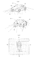
そのため、車両に複数の車外撮影用カメラを搭載し、それらのカメラで撮影した画像を合成し、あたかも車両の上方に設置したカメラから車両の周囲を撮影しているような画像を形成してモニタに表示することが提案されている。そのような複数のカメラを用いる際には例えば図7に示すように、車両11の右側を撮影する車両右側撮影用カメラ12、車両11の左側を撮影する車両左側撮影用カメラ13、車両11の後方を撮影する車両後方撮影用カメラ14、車両11の前側を撮影する車両前方撮影用カメラ15の合計4個のカメラを搭載して、これらのカメラの全ての画像を合成し、例えば図7(c)に略示するように、あたかも車両の真上に設けた1つのカメラにより車両11の全周囲を撮影しているような画像をモニタに表示することが提案されている。この方式はトップビューシステムともいわれ、車両の外部を撮影するカメラは必要に応じて2個、3個と適宜選択され、また設置位置も種々の位置に選択して設置される。
Therefore, a plurality of cameras for shooting outside the vehicle are mounted on the vehicle, the images shot by these cameras are combined, and an image is formed as if the surroundings of the vehicle were shot from the camera installed above the vehicle. It has been proposed to be displayed. When using such a plurality of cameras, for example, as shown in FIG. 7, a vehicle right
なお、車外監視カメラとして同方向を撮影する通常のカメラと赤外線カメラを用い、通常のカメラの撮影映像をモニタに表示すると共に、赤外線カメラにより危険物を監視し、危険物が存在するときにはその物体の位置を測定し、モニタに表示している通常のカメラ映像におけるその物体が存在する位置の映像部分の輝度を高める等により危険物を見やすく表示する技術は特許文献1に開示されている。また、奥行き位置の異なる複数の表示面にそれぞれ二次元像を表示し、各二次元像の輝度を変化させることにより立体画像を表示する技術は特許文献2に開示されている。
前記のようにトップビューによって車両周囲を画像表示すると、一般には周囲の状況を見やすく表示することができるが、立体物の表示に関しては、立体物が倒れ込んで表示されるため、それが立体物か平面状の物であるかの区別を直感的に認識することが困難であった。また、例えば道路や駐車場で周囲に縁石があり、その部分から高くなっているときも、周囲の物体が同色のため画面上からその状態を容易に把握することは困難であった。 When the image of the vehicle surroundings is displayed with the top view as described above, it is generally possible to display the surrounding situation in an easy-to-see manner. However, regarding the display of the three-dimensional object, the three-dimensional object is displayed in a collapsed state. It was difficult to intuitively recognize the distinction of a flat object. Also, for example, when there is a curb around the road or parking lot, and the height is high from that part, it is difficult to easily grasp the state from the screen because the surrounding objects are the same color.
したがって本発明は、車外を撮影するカメラで撮影した画像を合成することにより、車両の上方に仮想視点があるトップビュー画像を表示するに際して、車両周囲の立体物を容易に、且つ確実に認識することができるようにした距離画像によるトップビュー表示装置を提供することを主たる目的とする。 Therefore, the present invention recognizes a three-dimensional object around the vehicle easily and reliably when a top view image having a virtual viewpoint above the vehicle is displayed by synthesizing images taken by a camera that captures the outside of the vehicle. It is a main object of the present invention to provide a top view display device using a distance image that can be used.
本発明に係る距離画像によるトップビュー表示装置は、前記課題を解決するため、車外を撮影するカメラの撮影画像を取り込むカメラ画像取込部と、前記カメラ画像取込部の画像により、車両の上方に仮想視点がある車両周囲の画像を合成するトップビュー画像形成部と、前記カメラ画像取込部の画像により、立体物を検出する距離画像処理部と、前記距離画像処理部によって得られた立体物の高さ情報により、所定の高さ以上の立体物を他とは異なった態様で表示するトップビュー画像内立体物表示処理部とを備えたことを特徴とする。 In order to solve the above-described problem, a top view display device using a distance image according to the present invention has a camera image capturing unit that captures a captured image of a camera that captures the outside of the vehicle, and an image of the camera image capturing unit. A top view image forming unit that synthesizes an image around the vehicle with a virtual viewpoint, a distance image processing unit that detects a three-dimensional object based on an image of the camera image capturing unit, and a three-dimensional image obtained by the distance image processing unit A top-view three-dimensional object display processing unit for displaying a three-dimensional object having a predetermined height or more in a different manner from the others based on the object height information is provided.
また、本発明に係る他の距離画像によるトップビュー表示装置は、前記トップビュー表示装置において、前記所定の高さ以上の立体物を、高さが高い程輝度、または彩度、または色度を次第に変化させて表示することを特徴とするものである。また、前記所定の高さ以上の立体物を、同色で塗り潰して表示することを特徴とし、また、前記所定の高さ以上の立体物を、白色で表示することを特徴とし、更に、前記所定の高さ以上の立体物表示は、画面表示中で最も高い立体物を他とは異なった態様で表示することを特徴とする。 The top-view display device using another distance image according to the present invention may be configured such that, in the top-view display device, a three-dimensional object having a predetermined height or more has a higher brightness, saturation, or chromaticity. The display is characterized by being gradually changed. Further, the three-dimensional object having the predetermined height or higher is displayed by being filled with the same color, and the three-dimensional object having the predetermined height or higher is displayed in white, and the predetermined object is further displayed. The three-dimensional object display having a height equal to or higher than the height is characterized in that the highest three-dimensional object in the screen display is displayed in a mode different from the others.
本発明は上記のように構成したので、車外を撮影する複数のカメラで撮影した画像を合成することにより、車両の上方に仮想視点があるトップビュー画像を表示するに際して、車両にとって障害物となる車両周囲の立体物を容易に認識することができるようになる。 Since the present invention is configured as described above, it becomes an obstacle for a vehicle when displaying a top view image having a virtual viewpoint above the vehicle by combining images captured by a plurality of cameras that capture the outside of the vehicle. It becomes possible to easily recognize a three-dimensional object around the vehicle.
本発明は、トップビュー画像表示に際して、車両にとって障害物となる立体物を容易に認識することができるようにするという目的を、車外を撮影するカメラの撮影画像を取り込むカメラ画像取込部と、前記カメラ画像取込部の画像により、車両の上方に仮想視点がある車両周囲の画像を合成するトップビュー画像形成部と、前記カメラ画像取込部の画像により、立体物を検出する距離画像処理部と、前記距離画像処理部によって得られた立体物の高さ情報により、所定の高さ以上の立体物を他とは異なった態様で表示することにより実現した。 The present invention provides a camera image capturing unit that captures a captured image of a camera that captures the outside of a vehicle for the purpose of easily recognizing a three-dimensional object that becomes an obstacle for a vehicle when displaying a top view image. A top-view image forming unit that synthesizes an image around the vehicle with a virtual viewpoint above the vehicle from the image of the camera image capturing unit, and a distance image process that detects a three-dimensional object from the image of the camera image capturing unit This is realized by displaying a three-dimensional object having a predetermined height or higher in a different manner from the other, based on the height information of the three-dimensional object obtained by the unit and the distance image processing unit.
図1は本発明の実施例の機能ブロック図を示す。図1に示す実施例においては、前記図7に示すように、車外を撮影する複数のカメラの撮影画像を取り込むカメラ画像取込部1を備え、ここで取り込んだ画像は従来と同様に車両の上方に仮想視点のある画像を合成するトップビュー画像形成部2に入力するとともに、カメラ画像取込部1で取り込んだ複数のカメラ画像の内、例えば左右のカメラ等の複数のカメラの画像を選択して立体画像を形成する距離画像処理部3にも入力する。
FIG. 1 shows a functional block diagram of an embodiment of the present invention. In the embodiment shown in FIG. 1, as shown in FIG. 7, a camera
距離画像処理部3では、例えば図3に示すような従来から周知のエピポーラ幾何を用いたステレオ法により、距離画像を得ることができる。即ち、このステレオ法による距離画像処理においては、3次元空間上の注視点Pが2つの球面画像へP1、P2として射影されたとき、各点はエピポーラ線上に存在して、3次元空間上の注視点Pと射影された点P1、P2及びカメラの光学中心は一つの平面上に存在し、この平面はエピポーラ平面と呼ばれる。また、この幾何学的な光束はエピポーラ幾何と呼ばれ、エピポーラ方程式を満たす。その方程式に実測値を与えて解くことにより距離画像を得ることができる。
In the distance
距離画像を得る立体物画像処理としては、前記のようなエピポーラ幾何を用いたステレオ画像法以外にも、従来から用いられている例えば照度差ステレオ法やヘルムホルツステレオ法等、各種の立体物画像処理手法を用いることができる。また、その際には複数のカメラの画像により立体物の存在を知る以外に、1つのカメラによっても車両の移動により同じカメラが撮影した画像を分析することにより立体物の存在を知ることもでき、これらの手法を用いて立体物の高さを知るための距離画像処理を行うこともできる。 As the three-dimensional object image processing for obtaining the distance image, in addition to the stereo image method using the epipolar geometry as described above, various three-dimensional object image processing such as the illuminance difference stereo method and the Helmholtz stereo method conventionally used are used. Techniques can be used. In this case, in addition to knowing the existence of a three-dimensional object from images of a plurality of cameras, it is also possible to know the existence of a three-dimensional object by analyzing an image taken by the same camera by moving a vehicle with one camera. The distance image processing for knowing the height of the three-dimensional object can also be performed using these methods.
立体物画像表示処理部4では、このようなステレオ法により画像処理を行った画像データによって、後述するような種々の手法の内、例えば高さに応じて明るさを変える等の任意の手法によって立体物を表示する。トップビュー画像内立体物表示処理部5においては、前記のようにしてトップビュー画像形成部2で形成したトップビュー画像の中に、立体物画像表示処理部4で処理した立体物を表示するための処理を行う。それにより、従来は単にトップビュー画像しか形成されていない画像に対して、立体物が存在することを各種の手法により見やすく表示することができる。
The three-dimensional object image display processing unit 4 uses various methods such as changing the brightness according to the height, among various methods as will be described later, according to the image data subjected to the image processing by the stereo method. A solid object is displayed. In the top-view image three-dimensional object
前記のようにして得られた距離画像による立体物表示は、例えば図4に示すように高さによって輝度を変える手法採用する。同図においては周囲が壁に囲まれた車庫に車両を入れるとき、地面を含む平面を最も濃くし、高さ20cm、40cm、60cm、80cmと、立体物の高さが高い程その部分を明るく表示する。それにより平面と立体物の違いが明瞭に区別され、且つその高さの程度も容易に把握することができるようになる。このような高さによって異なった表示は、前記とは逆に立体物が高い程濃い色で表示し、或いは立体物が高い程青から赤に変化する画像にする等の、色の差によって表示する等々、種々の手法で表示することができる。即ち、立体物が高い程、輝度、彩度、色度のいずれかを次第に変化させることにより表示する。 The three-dimensional object display based on the distance image obtained as described above employs a method of changing the luminance depending on the height, for example, as shown in FIG. In this figure, when a vehicle is put into a garage surrounded by walls, the plane including the ground is darkest, and the height of the solid object becomes higher as the height of the solid object is 20cm, 40cm, 60cm, 80cm. indicate. Thereby, the difference between a plane and a three-dimensional object can be clearly distinguished, and the height can be easily grasped. Contrary to the above, the display different depending on the height is displayed by a color difference such that the higher the three-dimensional object is, the darker the color is displayed, or the higher the three-dimensional object is, the image changes from blue to red. It can be displayed by various methods. That is, as the three-dimensional object is higher, the display is performed by gradually changing any one of luminance, saturation, and chromaticity.
そのほか例えば図5(a)に示すように、立体物部分を同色の色で塗り潰しても良い。即ち、図示の車庫の場合は、平面Gは通常の画面とし、検出された立体物としての壁Wは例えば薄黄色のマスクをかけて、画面上では立体物を単に薄黄色に塗り潰した表示を行う。このように立体物を塗り潰すことにより、そこに立体物が存在することを示し、それが何であるかを示さないようにし、画像を見て立体物が何であるかの認識の誤りによってその立体物に衝突し、或いは立体物の認識により意識をし過ぎ、かえってその立体物に近づいてしまう心理による事故の発生の防止が可能となる。 In addition, for example, as shown in FIG. 5A, the three-dimensional object portion may be filled with the same color. That is, in the case of the illustrated garage, the plane G is a normal screen, and the detected wall W as a three-dimensional object is covered with a light yellow mask, for example, and the three-dimensional object is simply painted light yellow on the screen. Do. By painting a solid object in this way, it shows that there is a solid object there, does not indicate what it is, and sees the image by recognizing what the three-dimensional object is. It is possible to prevent the occurrence of an accident due to a psychology that collides with an object or becomes too conscious by recognizing a three-dimensional object and instead approaches the three-dimensional object.
また、図5(b)に示すように、地面Gは通常の撮影画像とし、立体物としての壁Wは全て白色として、平面状のものと立体物との区別をつけるようにしても良い。このように立体物を全て白色にすることによっても、立体物が何であるかを示さないようにし、運転者に立体物の誤認を与え、或いは過度の意識を持たせないようにすることができる。 Further, as shown in FIG. 5B, the ground G may be a normal photographed image, and the walls W as solid objects may be all white so as to distinguish between a planar object and a solid object. Even if the three-dimensional object is all white as described above, it is possible not to indicate what the three-dimensional object is, and to give the driver a misunderstanding of the three-dimensional object or not to give excessive consciousness. .
更に例えば図6(a)に示すように、屋外駐車場等における高さ15cm程度の車止めSについても、車両周囲全体の中で最も高い部分を計算し、その部分を濃く表示し、或いは赤く表示する等によってこれを強調表示することにより、本来は周囲と同色となって見にくい車止めSも、画面上では極めて明瞭に見ることができるようになる。その際には最初に表示画面内で例えば20cm以上高い特に重要な障害物の検出を行い、そのようなものが存在しないときには前記のように画面内で最も高いものの検出を行い、そのものが10〜20cmであるときにそのものを前記のように強調表示するようにしても良い。 Further, for example, as shown in FIG. 6 (a), for a car stop S having a height of about 15 cm in an outdoor parking lot or the like, the highest part of the entire vehicle periphery is calculated, and the part is displayed darkly or displayed in red. By highlighting this, for example, the car stop S that is originally the same color as the surroundings and is difficult to see can be seen very clearly on the screen. In that case, first, a particularly important obstacle higher than 20 cm, for example, is detected in the display screen, and when there is no such object, the highest one is detected in the screen as described above. When it is 20 cm, it may be highlighted as described above.
また、同図(b)のように、車の後の方に縁石Eがあるとき、前記の表示手法により、周囲において最も高くなっているこの部分を濃く、或いは赤い表示等によって明瞭に示すことができる。このように、表示画像の中で最も高い部分を選択して示すことにより、20cm程度の比較的低い物体であっても、車両にとって注意すべき物体として明瞭に示すことができるようになる。 Also, as shown in the figure (b), when there is a curbstone at the rear of the car, this part, which is the highest in the surroundings, should be clearly indicated by a dark or red display etc. Can do. Thus, by selecting and showing the highest part in the display image, even a relatively low object of about 20 cm can be clearly shown as an object to be noted for the vehicle.
図1に示すような機能ブロックからなり、前記のような種々の立体物表示を行う本発明においては、例えば図2に示す作動フローにしたがって順に作動を行うことにより実施することができる。即ち図2に示すトップビュー画像内への立体物表示処理においては、最初複数カメラからの画像の取り込みを行い(ステップS1)、その後そのカメラ画像を合成処理し、トップビュー画像を形成する(ステップS2)。この作動は図1のカメラ画像取込部1によって画像の取り込みを行い、トップビュー画像形成部2においてトップビュー画像を形成することにより行われる。
In the present invention, which is composed of functional blocks as shown in FIG. 1 and displays various three-dimensional objects as described above, for example, it can be implemented by sequentially operating according to the operation flow shown in FIG. That is, in the three-dimensional object display process in the top view image shown in FIG. 2, images are first captured from a plurality of cameras (step S1), and then the camera images are combined to form a top view image (step S1). S2). This operation is performed by capturing an image with the camera
次いで複数カメラ画像の中から、例えば左右のカメラ等の複数のカメラを選択してステレオ画像処理を行い(ステップS3)、その撮影画像から3次元座標を取得する(ステップS4)。この3次元座標により得られた高さ情報を含む立体物に対して、例えば高さが高い程明るく表示する等の、前記のような種々の態様の立体物画像表示処理を行う(ステップS5)。その後前記ステップS2で得られたトップビュー画像に対して、ステップS5で得られた立体物画像を合成処理し、前記図4〜6で示したような種々の態様で立体物の表示を行う。 Next, from a plurality of camera images, for example, a plurality of cameras such as left and right cameras are selected and stereo image processing is performed (step S3), and three-dimensional coordinates are acquired from the captured images (step S4). For the three-dimensional object including the height information obtained by the three-dimensional coordinates, for example, the three-dimensional object image display processing of various aspects as described above is performed (step S5). . Thereafter, the three-dimensional object image obtained in step S5 is combined with the top view image obtained in step S2, and the three-dimensional object is displayed in various modes as shown in FIGS.
1 カメラ画像取込部
2 トップビュー画像形成部
3 距離画像処理部
4 立体物画像表示処理部
5 トップビュー画像内立体物表示処理部
DESCRIPTION OF
Claims (5)
前記カメラ画像取込部の画像により、車両の上方に仮想視点がある車両周囲の画像を合成するトップビュー画像形成部と、
前記カメラ画像取込部の画像により、立体物を検出する距離画像処理部と、
前記距離画像処理部によって得られた立体物の高さ情報により、所定の高さ以上の立体物を他とは異なった態様で表示するトップビュー画像内立体物表示処理部とを備えたことを特徴とする距離画像によるトップビュー表示装置。 A camera image capturing unit that captures a captured image of a camera that captures the outside of the vehicle;
A top-view image forming unit that synthesizes an image around the vehicle with a virtual viewpoint above the vehicle, based on the image of the camera image capturing unit;
A distance image processing unit that detects a three-dimensional object from the image of the camera image capturing unit;
A solid object display processing unit in a top view image that displays a solid object of a predetermined height or higher in a different manner from the other, based on the height information of the solid object obtained by the distance image processing unit. A top view display device with a characteristic distance image.
Priority Applications (1)
| Application Number | Priority Date | Filing Date | Title |
|---|---|---|---|
| JP2007216542A JP2009049943A (en) | 2007-08-22 | 2007-08-22 | Top view display unit using range image |
Applications Claiming Priority (1)
| Application Number | Priority Date | Filing Date | Title |
|---|---|---|---|
| JP2007216542A JP2009049943A (en) | 2007-08-22 | 2007-08-22 | Top view display unit using range image |
Publications (1)
| Publication Number | Publication Date |
|---|---|
| JP2009049943A true JP2009049943A (en) | 2009-03-05 |
Family
ID=40501678
Family Applications (1)
| Application Number | Title | Priority Date | Filing Date |
|---|---|---|---|
| JP2007216542A Withdrawn JP2009049943A (en) | 2007-08-22 | 2007-08-22 | Top view display unit using range image |
Country Status (1)
| Country | Link |
|---|---|
| JP (1) | JP2009049943A (en) |
Cited By (11)
| Publication number | Priority date | Publication date | Assignee | Title |
|---|---|---|---|---|
| JP2013205402A (en) * | 2012-03-29 | 2013-10-07 | Sumitomo (Shi) Construction Machinery Co Ltd | Periphery monitoring apparatus for working machine |
| CN103770703A (en) * | 2012-10-19 | 2014-05-07 | 纳诺科技股份有限公司 | Driving image identification device and method thereof |
| KR101428281B1 (en) * | 2012-12-12 | 2014-08-07 | 현대자동차주식회사 | System for detecting road-kerb of veichle and method thereof |
| KR101491238B1 (en) * | 2013-02-27 | 2015-02-11 | 현대자동차주식회사 | System and method for detecting of speed bump |
| WO2015125544A1 (en) * | 2014-02-18 | 2015-08-27 | Nkワークス株式会社 | Information processing device, information processing method, and program |
| WO2015125545A1 (en) * | 2014-02-18 | 2015-08-27 | Nkワークス株式会社 | Information processing device, information processing method, and program |
| WO2015141268A1 (en) * | 2014-03-20 | 2015-09-24 | Nkワークス株式会社 | Information processing apparatus, information processing method, and program |
| JP2017200182A (en) * | 2011-09-06 | 2017-11-02 | ジャガー ランド ローバー リミテッドJaguar Land Rover Limited | Topographic visualization for vehicle and vehicle driver |
| US20180215413A1 (en) | 2017-02-02 | 2018-08-02 | Aisin Seiki Kabushiki Kaisha | Parking assist apparatus |
| US20180319337A1 (en) * | 2016-05-10 | 2018-11-08 | JVC Kenwood Corporation | Vehicle display device, vehicle display method, and recording medium for displaying images |
| JP2020161895A (en) * | 2019-03-25 | 2020-10-01 | 国立大学法人 東京大学 | Overlooking video presentation system |
-
2007
- 2007-08-22 JP JP2007216542A patent/JP2009049943A/en not_active Withdrawn
Cited By (20)
| Publication number | Priority date | Publication date | Assignee | Title |
|---|---|---|---|---|
| JP2017200182A (en) * | 2011-09-06 | 2017-11-02 | ジャガー ランド ローバー リミテッドJaguar Land Rover Limited | Topographic visualization for vehicle and vehicle driver |
| JP2013205402A (en) * | 2012-03-29 | 2013-10-07 | Sumitomo (Shi) Construction Machinery Co Ltd | Periphery monitoring apparatus for working machine |
| US9715015B2 (en) | 2012-03-29 | 2017-07-25 | Sumitomo(S.H.I.) Construction Machinery Co., Ltd. | Periphery-monitoring device for working machines |
| CN103770703A (en) * | 2012-10-19 | 2014-05-07 | 纳诺科技股份有限公司 | Driving image identification device and method thereof |
| KR101428281B1 (en) * | 2012-12-12 | 2014-08-07 | 현대자동차주식회사 | System for detecting road-kerb of veichle and method thereof |
| KR101491238B1 (en) * | 2013-02-27 | 2015-02-11 | 현대자동차주식회사 | System and method for detecting of speed bump |
| WO2015125544A1 (en) * | 2014-02-18 | 2015-08-27 | Nkワークス株式会社 | Information processing device, information processing method, and program |
| WO2015125545A1 (en) * | 2014-02-18 | 2015-08-27 | Nkワークス株式会社 | Information processing device, information processing method, and program |
| CN106415654A (en) * | 2014-02-18 | 2017-02-15 | 诺日士精密株式会社 | Information processing device, information processing method, and program |
| JPWO2015125544A1 (en) * | 2014-02-18 | 2017-03-30 | ノーリツプレシジョン株式会社 | Information processing apparatus, information processing method, and program |
| JPWO2015141268A1 (en) * | 2014-03-20 | 2017-04-06 | ノーリツプレシジョン株式会社 | Information processing apparatus, information processing method, and program |
| CN105940428A (en) * | 2014-03-20 | 2016-09-14 | 诺日士精密株式会社 | Information processing apparatus, information processing method, and program |
| WO2015141268A1 (en) * | 2014-03-20 | 2015-09-24 | Nkワークス株式会社 | Information processing apparatus, information processing method, and program |
| US20180319337A1 (en) * | 2016-05-10 | 2018-11-08 | JVC Kenwood Corporation | Vehicle display device, vehicle display method, and recording medium for displaying images |
| US10703271B2 (en) | 2016-05-10 | 2020-07-07 | JVC Kenwood Corporation | Vehicle display device, vehicle display method, and recording medium for displaying images |
| US20180215413A1 (en) | 2017-02-02 | 2018-08-02 | Aisin Seiki Kabushiki Kaisha | Parking assist apparatus |
| EP3357793A1 (en) | 2017-02-02 | 2018-08-08 | Aisin Seiki Kabushiki Kaisha | Parking assist apparatus |
| US10308283B2 (en) | 2017-02-02 | 2019-06-04 | Aisin Seiki Kabushiki Kaisha | Parking assist apparatus |
| JP2020161895A (en) * | 2019-03-25 | 2020-10-01 | 国立大学法人 東京大学 | Overlooking video presentation system |
| JP7162218B2 (en) | 2019-03-25 | 2022-10-28 | 国立大学法人 東京大学 | Bird's eye view presentation system |
Similar Documents
| Publication | Publication Date | Title |
|---|---|---|
| JP2009049943A (en) | Top view display unit using range image | |
| US10899277B2 (en) | Vehicular vision system with reduced distortion display | |
| JP4707109B2 (en) | Multi-camera image processing method and apparatus | |
| US11472338B2 (en) | Method for displaying reduced distortion video images via a vehicular vision system | |
| US8044781B2 (en) | System and method for displaying a 3D vehicle surrounding with adjustable point of view including a distance sensor | |
| JP5210994B2 (en) | Image display device for vehicle | |
| US20150042799A1 (en) | Object highlighting and sensing in vehicle image display systems | |
| US20090022423A1 (en) | Method for combining several images to a full image in the bird's eye view | |
| US8477191B2 (en) | On-vehicle image pickup apparatus | |
| KR20190047027A (en) | How to provide a rearview mirror view of the vehicle's surroundings in the vehicle | |
| JP5546321B2 (en) | In-vehicle display device using multiple camera images | |
| KR102045088B1 (en) | Image displaying Method and Apparatus therefor | |
| JPWO2014129026A1 (en) | Driving support device and image processing program | |
| JP4200343B2 (en) | Monitor device | |
| KR20180085718A (en) | METHOD AND APPARATUS FOR CALCULATING INTERACTIVE AREA IN VEHICLE AREA | |
| JP2010160606A (en) | Information presentation system for vehicle | |
| US9396401B2 (en) | Obstacle alarm device | |
| JP2010018102A (en) | Driving support device | |
| JP4600999B2 (en) | Vehicle perimeter monitoring device | |
| JP4614852B2 (en) | Vehicle surrounding monitoring method and apparatus | |
| JP4986070B2 (en) | Ambient monitoring device for vehicles | |
| JP5845909B2 (en) | Obstacle alarm device | |
| JP5974476B2 (en) | Obstacle alarm device | |
| JP5787168B2 (en) | Obstacle alarm device | |
| US9773172B2 (en) | Obstacle alert device |
Legal Events
| Date | Code | Title | Description |
|---|---|---|---|
| A300 | Application deemed to be withdrawn because no request for examination was validly filed |
Free format text: JAPANESE INTERMEDIATE CODE: A300 Effective date: 20101102 |