JP5192372B2 - X-ray CT system - Google Patents
X-ray CT system Download PDFInfo
- Publication number
- JP5192372B2 JP5192372B2 JP2008517885A JP2008517885A JP5192372B2 JP 5192372 B2 JP5192372 B2 JP 5192372B2 JP 2008517885 A JP2008517885 A JP 2008517885A JP 2008517885 A JP2008517885 A JP 2008517885A JP 5192372 B2 JP5192372 B2 JP 5192372B2
- Authority
- JP
- Japan
- Prior art keywords
- ray
- current time
- time product
- tube
- tube current
- Prior art date
- Legal status (The legal status is an assumption and is not a legal conclusion. Google has not performed a legal analysis and makes no representation as to the accuracy of the status listed.)
- Expired - Fee Related
Links
Images

Classifications
-
- A—HUMAN NECESSITIES
- A61—MEDICAL OR VETERINARY SCIENCE; HYGIENE
- A61B—DIAGNOSIS; SURGERY; IDENTIFICATION
- A61B6/00—Apparatus for radiation diagnosis, e.g. combined with radiation therapy equipment
- A61B6/02—Devices for diagnosis sequentially in different planes; Stereoscopic radiation diagnosis
- A61B6/03—Computerised tomographs
- A61B6/032—Transmission computed tomography [CT]
-
- A—HUMAN NECESSITIES
- A61—MEDICAL OR VETERINARY SCIENCE; HYGIENE
- A61B—DIAGNOSIS; SURGERY; IDENTIFICATION
- A61B6/00—Apparatus for radiation diagnosis, e.g. combined with radiation therapy equipment
- A61B6/54—Control of apparatus or devices for radiation diagnosis
- A61B6/542—Control of apparatus or devices for radiation diagnosis involving control of exposure
-
- A—HUMAN NECESSITIES
- A61—MEDICAL OR VETERINARY SCIENCE; HYGIENE
- A61B—DIAGNOSIS; SURGERY; IDENTIFICATION
- A61B6/00—Apparatus for radiation diagnosis, e.g. combined with radiation therapy equipment
- A61B6/54—Control of apparatus or devices for radiation diagnosis
- A61B6/545—Control of apparatus or devices for radiation diagnosis involving automatic set-up of acquisition parameters
Abstract
Description
本発明は、X線CT装置に係り、特に診断対象を識別するために適切なコントラストノイズ比を得るためのX線条件をスキャン開始前に予め決定する機能を有するX線CT装置に関する。 The present invention relates to an X-ray CT apparatus, and more particularly to an X-ray CT apparatus having a function of predetermining an X-ray condition for obtaining an appropriate contrast-to-noise ratio for identifying a diagnosis target before starting scanning.
X線CT装置には、1回のX線曝射で、一つの断層画像が得られるシングルスライス型X線CT装置と、同時に複数の断層画像が得られるマルチスライス型X線CT装置とがある。 X-ray CT apparatuses include a single slice type X-ray CT apparatus that can obtain one tomographic image by one X-ray exposure and a multi-slice type X-ray CT apparatus that can simultaneously obtain a plurality of tomographic images. .
前記シングルスライス型X線CT装置は、多数のX線検出素子を1列、すなわち一次元方向(チャネル方向)に配列したX線検出器を用い、被検体にファンビーム、すなわち扇形のX線ビームをX線管から照射し、前記被検体透過後のX線を計測して被検体の投影データを得る。 The single slice type X-ray CT apparatus uses an X-ray detector in which a large number of X-ray detection elements are arranged in one row, that is, in a one-dimensional direction (channel direction), and a fan beam, that is, a fan-shaped X-ray beam Is irradiated from an X-ray tube, and X-rays transmitted through the subject are measured to obtain projection data of the subject.
これに対して、前記マルチスライス型X線CT装置は、被検体にコーンビーム、すなわち円錐形もしくは角錐形のX線ビームをX線管から照射し、多数のX線検出素子を二次元方向(チャネル方向と列方向)に配列したX線検出器によって前記被検体透過後のX線を計測して被検体の投影データを得る。 On the other hand, the multi-slice X-ray CT apparatus irradiates a subject with a cone beam, that is, a cone-shaped or pyramid-shaped X-ray beam from an X-ray tube, and places a number of X-ray detection elements in a two-dimensional direction ( The projection data of the subject is obtained by measuring the X-rays transmitted through the subject with an X-ray detector arranged in the channel direction and the column direction).
いずれのX線CT装置においても、対向するX線管とX線検出器とを被検体の周囲に回転させて多方向からの投影データを収集し、この収集した投影データにぼけ補正のための再構成フィルタ処理を行った上で逆投影して被検体の断層像を再構成する。 In any X-ray CT apparatus, the opposing X-ray tube and the X-ray detector are rotated around the subject to collect projection data from multiple directions, and the collected projection data is used for blur correction. After performing the reconstruction filter processing, back projection is performed to reconstruct a tomographic image of the subject.
前記投影データは、離散的なX線管の位置(以下、「ビュー」と呼ぶ)において収集され、この収集された投影データを「該当ビューにおける投影データ」と呼び、前記被検体の周囲を回転するX線管とX線検出器の1回転あたりのビュー数は、通常、数百から数千にまでおよび、1枚のCT画像を再構成するために必要なビュー数の投影データを収集する動作を「スキャン」と呼ぶ。
また、1ビュー分の投影データは、前記X線検出器のチャネル数×列数分のデータから成る(シングルスライス型X線CT装置は前記のとおり列数=1の場合である)。The projection data is collected at discrete X-ray tube positions (hereinafter referred to as “views”). The collected projection data is referred to as “projection data in the corresponding view” and rotates around the subject. The number of views per rotation of the X-ray tube and the X-ray detector, which normally ranges from several hundred to several thousand, is collected for projection data of the number of views necessary to reconstruct one CT image The operation is called “scan”.
Further, projection data for one view consists of data for the number of channels of the X-ray detector × number of columns (in the case of the single slice X-ray CT apparatus, the number of columns = 1 as described above).
このようなX線CT装置において、得られた断層像内の診断対象を識別するために、診断対象とその周囲とのCT値差の絶対値を画像ノイズ標準偏差値(以下、「画像SD(Standard Deviation)値」と記載)で除した値、すなわちコントラストノイズ比(Contrast Noise Ratio、以下「CNR」と記載)が重要な画質指標である。 In such an X-ray CT apparatus, in order to identify the diagnostic object in the obtained tomographic image, the absolute value of the CT value difference between the diagnostic object and its surroundings is calculated as an image noise standard deviation value (hereinafter referred to as “image SD ( The value divided by “Standard Deviation”), that is, the contrast noise ratio (hereinafter referred to as “CNR”) is an important image quality index.
前記X線CT装置の画質指標において、一般的には被曝線量を増大させることによりCNRが向上し、診断用画像として良質な画像となるが、その一方で患者の被曝線量は極力少なく抑えることが望ましい。
そこで、被曝線量・画像SD値を増大させないようにしつつ従来より低い管電圧(X線管の陽極と陰極間に印加する電圧)を使用することで再構成画像におけるCNRを向上させる、あるいは再構成画像におけるCNRを減少させないようにしつつ従来より低い管電圧を使用することで被曝線量を低減するX線CT装置が特許文献1に開示されている。
Therefore, the CNR in the reconstructed image is improved or reconstructed by using a lower tube voltage (voltage applied between the anode and cathode of the X-ray tube) while not increasing the exposure dose and the image SD value.
しかしながら、上記特許文献1に開示されているX線CT装置は、実際には画像SD値に着目したX線条件最適化を行っているものであり、コントラスト(ここではCT値差の絶対値)もしくはCNRとX線条件との関係は十分に検討されていない。
例えば、臓器間のコントラストは必ずしも管電圧に大きく依存しないので、画像SD値が増大しないようにしつつ従来より低い管電圧を使用しても、CNRの向上には必ずしも有効ではない。However, the X-ray CT apparatus disclosed in
For example, since the contrast between organs does not necessarily depend greatly on the tube voltage, using a tube voltage lower than the conventional one while preventing the image SD value from increasing is not necessarily effective in improving the CNR.
また実際にCNRを保ちながら被曝線量を低減可能なプロセスがどのようなものになるかが明確ではない。
さらに診断対象のサイズによって実現すべきCNRが異なり、したがって設定すべきX線条件も異なるが、その点についても検討されてはいない。In addition, it is not clear what kind of process can reduce the exposure dose while maintaining the CNR.
Furthermore, the CNR to be realized differs depending on the size of the diagnosis target, and therefore the X-ray conditions to be set differ, but this point has not been studied.
そこで本発明は、診断対象を識別するために適切なCNRを達成し得るX線条件を決定する機能を有するX線CT装置を提供することを目的とする。 Accordingly, an object of the present invention is to provide an X-ray CT apparatus having a function of determining an X-ray condition that can achieve an appropriate CNR for identifying a diagnosis target.
上記の目的を達成するため、本発明のX線CT装置は以下のように構成される。
すなわち、被検体に照射するX線を発生するX線管と、前記被検体を挟み前記X線管と対向配置され被検体を透過したX線を検出するX線検出器と、前記X線管とX線検出器を搭載して前記被検体の周りを回転するスキャナ回転体と、スキャノグラム撮影及びスキャン撮影に必要な情報を入力及び設定して操作する操作手段と、前記X線検出器によって検出された被検体のスキャノグラム投影データに基づいてスキャン時の撮影条件を決定する撮影条件決定手段と、この撮影条件決定手段によって決定された撮影条件でスキャンするスキャン手段とを備え、このスキャン手段によってスキャンされ前記X線検出器で検出した透過X線量に基づいて前記被検体の断層像を再構成するX線CT装置において、前記撮影条件決定手段は、標準撮影条件を記憶する記憶手段と、前記スキャノグラム投影データを解析して前記被検体の3次元モデルを生成する被検体3次元モデル生成手段と、前記操作手段で前記被検体の診断対象サイズを設定する診断対象サイズ設定手段と、前記設定した診断対象サイズと前記被検体3次元モデルと前記標準撮影条件とから診断対象を識別するコントラストノイズ比を得るためのX線条件を算出するX線条件算出手段とを備える。In order to achieve the above object, the X-ray CT apparatus of the present invention is configured as follows.
That is, an X-ray tube that generates X-rays that irradiate the subject, an X-ray detector that sandwiches the subject and is opposed to the X-ray tube and detects the X-rays that have passed through the subject, and the X-ray tube And a scanner rotating body that rotates around the subject with an X-ray detector, operation means for inputting and setting information necessary for scanogram imaging and scan imaging, and detection by the X-ray detector An imaging condition determining unit that determines an imaging condition at the time of scanning based on the scanogram projection data of the subject, and a scanning unit that scans based on the imaging condition determined by the imaging condition determining unit. In the X-ray CT apparatus for reconstructing a tomographic image of the subject based on the transmitted X-ray dose detected by the X-ray detector, the imaging condition determining means includes a standard imaging condition. A storage means for storing the object, a subject three-dimensional model generation means for analyzing the scanogram projection data to generate a three-dimensional model of the subject, and a diagnosis target for setting the diagnosis target size of the subject by the operation means Size setting means, and X-ray condition calculation means for calculating an X-ray condition for obtaining a contrast noise ratio for identifying a diagnosis object from the set diagnosis object size, the subject three-dimensional model, and the standard imaging conditions Prepare.
本発明のX線CT装置は、さらに、X線条件算出手段が最終的に算出したX線条件(例えば管電圧及び管電流時間積)とこのX線条件とは異なるX線条件での撮影時における評価指標の予想値を表示する手段と、この表示手段に表示された評価指標の予想値に対応するX線条件を選択するX線条件選択手段とを備える。前記評価指標の予想値は、管電圧、管電流、被曝線量、診断対象の想定コントラスト値、コントラストノイズ比、画像ノイズ標準偏差値、診断対象の識別可能サイズ、消費X線管電力のうち少なくとも一つを含む。 The X-ray CT apparatus of the present invention further has an X-ray condition (for example, a tube voltage and a tube current time product) finally calculated by the X-ray condition calculation means and an X-ray condition different from the X-ray condition. Means for displaying the expected value of the evaluation index and X-ray condition selection means for selecting an X-ray condition corresponding to the predicted value of the evaluation index displayed on the display means. The expected value of the evaluation index is at least one of tube voltage, tube current, exposure dose, assumed contrast value of the diagnostic object, contrast noise ratio, image noise standard deviation value, identifiable size of the diagnostic object, and consumed X-ray tube power. Including one.
さらにまた、前記表示手段に表示された評価指標の予想値に対応するX線条件を選択するX線条件選択手段を備える。
本発明のX線CT装置において、前記X線条件算出手段は、以下、例示する種々の態様を採りえる。Furthermore, X-ray condition selection means for selecting an X-ray condition corresponding to the expected value of the evaluation index displayed on the display means is provided.
In the X-ray CT apparatus of the present invention, the X-ray condition calculating means can take various modes exemplified below.
前記X線条件算出手段は、前記標準撮影条件である標準管電圧および標準管電流時間積を用いた場合に、前記操作手段で設定した撮影範囲内の各スライス位置において実現される画像ノイズ標準偏差値の第1の予測値を算出する第1の画像ノイズ標準偏差予測値算出手段と、前記第1の画像ノイズ標準偏差予測値が前記撮影範囲内に設定した特定スライス位置範囲内において最大値となる参照スライス位置を算出する手段と、前記設定した診断対象のサイズから当該診断対象を識別するためのコントラストノイズ比を算出するコントラストノイズ比算出手段と、前記コントラストノイズ比算出手段が算出したコントラストノイズ比を用いて前記標準管電圧における第1の画像ノイズ標準偏差基準値を算出する手段と、前記第1の画像ノイズ標準偏差基準値を実現するための第1の管電流時間積を算出する第1の管電流時間積算出手段と、前記参照スライス位置において前記第1の管電流時間積を用いた場合の画像ノイズ標準偏差予測値が所定の上限値以下となる第1の管電圧を算出する手段と、前記参照スライス位置において前記第1の管電圧および前記第1の管電流時間積により実現される第2の画像ノイズ標準偏差基準値を算出する手段と、前記撮影範囲内の各スライス位置で前記第1の管電圧および前記第1の管電流時間積により実現される第2の画像ノイズ標準偏差値予測値を算出する手段と、前記第1の管電圧および前記第2の画像ノイズ標準偏差予測値と前記第2の画像ノイズ標準偏差基準値から前記撮影範囲内の各スライス位置において前記第2の画像ノイズ標準偏差基準値を実現するための第2の管電流時間積を算出する第2の管電流時間積算出手段とを備え、前記第1の管電圧および第2の管電流時間積をX線条件とする。 The X-ray condition calculating means uses the standard tube voltage and the standard tube current time product which are the standard imaging conditions, and the image noise standard deviation realized at each slice position within the imaging range set by the operation means. A first image noise standard deviation predicted value calculation means for calculating a first predicted value of the value, and the first image noise standard deviation predicted value is a maximum value within a specific slice position range set within the imaging range. Means for calculating a reference slice position, contrast noise ratio calculating means for calculating a contrast noise ratio for identifying the diagnosis object from the set size of the diagnosis object, and contrast noise calculated by the contrast noise ratio calculation means Means for calculating a first image noise standard deviation reference value at the standard tube voltage using a ratio; and the first image noise standard. A first tube current time product calculating means for calculating a first tube current time product for realizing the deviation reference value, and an image noise standard when the first tube current time product is used at the reference slice position. A second image realized by means for calculating a first tube voltage at which a deviation predicted value is less than or equal to a predetermined upper limit value, and the first tube voltage and the first tube current time product at the reference slice position Means for calculating a noise standard deviation reference value; and a second image noise standard deviation value predicted value realized by the first tube voltage and the first tube current time product at each slice position in the imaging range. Means for calculating, the second image noise standard at each slice position within the imaging range from the first tube voltage, the second image noise standard deviation predicted value, and the second image noise standard deviation reference value; side Second tube current time product calculating means for calculating a second tube current time product for realizing the reference value, wherein the first tube voltage and the second tube current time product are X-ray conditions. .
前記コントラストノイズ比算出手段、第1の画像SD基準値算出手段の具体的手段の一例は以下のとおりである。
(1)前記コントラストノイズ比算出手段は、前記コントラストノイズ比を、前記診断対象のサイズと識別可能なコントラストノイズ比との関係の関数より算出する手段である。An example of specific means of the contrast noise ratio calculating means and the first image SD reference value calculating means is as follows.
(1) The contrast noise ratio calculating means is a means for calculating the contrast noise ratio from a function of a relationship between the size of the diagnosis object and the distinguishable contrast noise ratio.
(2)前記第1の画像SD基準値算出手段は、前記第1の画像ノイズ標準偏差基準値を、前記記憶装置に記憶してある診断対象の標準管電圧における想定コントラスト値を前記コントラストノイズ比算出手段で算出したコントラストノイズで除算することにより算出する手段である。 (2) The first image SD reference value calculating means calculates the first image noise standard deviation reference value as an estimated contrast value in a standard tube voltage of a diagnosis target stored in the storage device, as the contrast noise ratio. It is a means for calculating by dividing by the contrast noise calculated by the calculating means.
また、前記X線条件算出手段は、前記診断対象サイズ設定手段で設定した前記被検体の診断対象における真陽性率と偽陽性率とを設定する真陽性率および偽陽性率設定手段と、前記設定した診断対象のサイズから当該診断対象を識別するためのコントラストノイズ比を算出するコントラストノイズ比算出手段と、前記被検体3次元モデルにおける同一撮影条件での画像ノイズ標準偏差値が最大になる参照スライス位置を算出するスライス位置算出手段と、想定コントラスト値と前記コントラストノイズ比算出手段で算出したコントラストノイズ比とから前記参照スライス位置における画像ノイズ標準偏差値を算出する画像ノイズ標準偏差値算出手段と、該画像ノイズ標準偏差値算出手段で算出した画像ノイズ標準偏差値を実現するための第1の管電流時間積を算出する管電流時間積算出手段と、前記第1の管電流時間積における、管電圧に依らずコントラストノイズ比を概一定にするための管電流時間積補正係数を算出する管電流時間積補正係数算出手段と、前記第1の管電流時間積を前記管電流時間積補正係数により補正する管電流時間積補正手段と、前記X線管で消費する電力が前記標準撮影条件であるX線管電力の基準値以下となる条件下で被曝線量を最小とする管電圧を算出する管電圧算出手段とを備え、前記管電圧算出手段が算出した管電圧および前記管電流時間積補正手段で補正した管電流時間積をX線条件とする。 In addition, the X-ray condition calculation unit includes a true positive rate and a false positive rate setting unit that sets a true positive rate and a false positive rate in the diagnosis target of the subject set by the diagnosis target size setting unit, and the setting A contrast noise ratio calculating means for calculating a contrast noise ratio for identifying the diagnosis object from the size of the diagnosis object, and a reference slice having a maximum image noise standard deviation value under the same imaging condition in the subject three-dimensional model Slice position calculating means for calculating a position; image noise standard deviation value calculating means for calculating an image noise standard deviation value at the reference slice position from an assumed contrast value and a contrast noise ratio calculated by the contrast noise ratio calculating means; First for realizing the image noise standard deviation value calculated by the image noise standard deviation value calculating means A tube current time product calculating means for calculating a tube current time product, and a tube for calculating a tube current time product correction coefficient for making the contrast noise ratio substantially constant regardless of the tube voltage in the first tube current time product. Current time product correction coefficient calculation means, tube current time product correction means for correcting the first tube current time product by the tube current time product correction coefficient, and power consumed by the X-ray tube in the standard imaging conditions Tube voltage calculation means for calculating a tube voltage that minimizes the exposure dose under a condition that is below a reference value of a certain X-ray tube power, and corrects the tube voltage calculated by the tube voltage calculation means and the tube current time product The tube current time product corrected by the means is taken as the X-ray condition.
前記コントラストノイズ比算出手段、前記想定コントラスト値、前記管電流時間積算出手段および前記管電流時間積補正係数算出手段の一例は以下のとおりである。 An example of the contrast noise ratio calculation means, the assumed contrast value, the tube current time product calculation means, and the tube current time product correction coefficient calculation means is as follows.
(3)前記コントラストノイズ比算出手段は、前記コントラストノイズ比を、前記診断対象サイズと識別可能なコントライスノイズ比との関係と、前記真陽性率と偽陽性率との関係と、前記識別可能なコントラストノイズ比と偽陽性率との関係とから算出する手段である。 (3) The contrast noise ratio calculating means can identify the contrast noise ratio, the relationship between the diagnostic object size and the distinguishable contrast noise ratio, the relationship between the true positive rate and the false positive rate, and the discrimination This is a means for calculating from the relationship between the contrast noise ratio and the false positive rate.
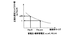
(4)前記想定コントラスト値は、前記標準撮影条件の標準管電圧における成人の平均被検体サイズとこの平均値で正規化した前記被検体の診断対象サイズに応じた造影効果との関係より求める。 (4) The assumed contrast value is obtained from the relationship between the average subject size of adults at the standard tube voltage under the standard imaging conditions and the contrast effect according to the size of the subject to be diagnosed normalized by this average value.
(5)前記管電流時間積算出手段は、前記第1の管電流時間積を、前記被検体サイズにおける画像ノイズ標準偏差値と管電流時間積の関係より求める手段である。 (5) The tube current time product calculating means is a means for obtaining the first tube current time product from the relationship between the image noise standard deviation value and the tube current time product at the subject size.
(6)前記管電流時間積補正係数算出手段は、前記補正係数を、前記被検体の所定のサイズにおける管電圧と正規化コントラストノイズ比の関係より求める手段である。 (6) The tube current time product correction coefficient calculating means is a means for obtaining the correction coefficient from a relationship between a tube voltage and a normalized contrast noise ratio at a predetermined size of the subject.
また、前記X線条件算出手段は、前記被検体3次元モデルにおける同一撮影条件での画像ノイズ標準偏差値が最大になる参照スライス位置を算出するスライス位置算出手段と、前記操作手段から目標の画像ノイズ標準偏差値を入力して設定する目標画像ノイズ標準偏差値設定手段と、前記参照スライス位置における想定コントラスト値と前記目標の画像ノイズ標準偏差値とから前記被検体の診断対象の識別可能なコントラストノイズ比を算出して診断対象サイズを算出する診断対象サイズ算出手段と、前記算出した診断対象サイズが現実の診断対象サイズとして適切か否かの判断を受け付ける診断対象サイズ判断入力手段と、前記算出した診断対象サイズが適切であると判断された場合に、前記参照スライス位置での前記診断対象サイズで前記目標の画像ノイズ標準偏差値を満たす第1の管電流時間積を算出する管電流時間積算出手段と、前記算出した診断対象サイズが適切でないと判断された場合に、前記診断対象サイズが妥当になるように目標の画像ノイズ標準偏差値を調整する画像ノイズ標準偏差値調整手段と、前記第1の管電流時間積における、管電圧に依らずコントラストノイズ比を概一定にするための前記管電流時間積補正係数を算出する管電流時間積補正係数算出手段と、前記第1の管電流時間積を前記管電流時間積補正係数により補正する管電流時間積補正手段と、前記X線管で消費する電力が前記標準撮影条件であるX線管電力の基準値以下となる条件下で被曝線量を最小とする管電圧を算出する管電圧算出手段とを備え、前記管電圧算出手段が算出した管電圧および前記管電流時間積補正手段で補正した管電流時間積をX線条件とする。 In addition, the X-ray condition calculation unit includes a slice position calculation unit that calculates a reference slice position that maximizes an image noise standard deviation value under the same imaging condition in the subject three-dimensional model, and a target image from the operation unit. Target image noise standard deviation value setting means for inputting and setting a noise standard deviation value, and an identifiable contrast of the object to be diagnosed from the assumed contrast value at the reference slice position and the target image noise standard deviation value A diagnostic target size calculating unit that calculates a noise target by calculating a noise ratio; a diagnostic target size determination input unit that receives a determination as to whether the calculated diagnostic target size is appropriate as an actual diagnostic target size; and the calculation If it is determined that the diagnosis target size is appropriate, the diagnosis target size at the reference slice position is A tube current time product calculating means for calculating a first tube current time product satisfying a target image noise standard deviation value, and when the calculated diagnosis object size is determined to be inappropriate, the diagnosis object size is appropriately determined Image noise standard deviation value adjusting means for adjusting a target image noise standard deviation value so that the tube current for making the contrast noise ratio substantially constant regardless of the tube voltage in the first tube current time product Tube current time product correction coefficient calculating means for calculating a time product correction coefficient, tube current time product correction means for correcting the first tube current time product by the tube current time product correction coefficient, and consumption by the X-ray tube Tube voltage calculating means for calculating a tube voltage that minimizes the exposure dose under the condition that the electric power to be performed is not more than the reference value of the X-ray tube power that is the standard imaging condition, and the tube calculated by the tube voltage calculating means Voltage The tube current time product corrected by the preliminary the tube current time product correction means are assumed as the X-ray condition.
前記想定コントラスト値、前記管電流時間積算出手段および前記管電流時間積補正係数算出手段の一例は以下のとおりである。 An example of the assumed contrast value, the tube current time product calculation means, and the tube current time product correction coefficient calculation means is as follows.
(7)前記想定コントラスト値は、前記診断対象サイズ算出手段で算出した診断対象サイズと前記参照スライス位置とに基づいて算出する。 (7) The assumed contrast value is calculated based on the diagnosis object size calculated by the diagnosis object size calculation means and the reference slice position.
(8)前記管電流時間積算出手段は、前記参照スライス位置および前記診断対象の所定のサイズにおける画像ノイズ標準偏差値と管電流時間積の関係より求める手段である。 (8) The tube current time product calculating means is a means for obtaining from the relationship between the reference slice position and the image noise standard deviation value at a predetermined size of the diagnosis target and the tube current time product.
(9)前記管電流時間積補正係数算出手段は、前記補正係数を、前記被検体の所定のサイズにおける管電圧と正規化コントラストノイズ比の関係より求める手段である。 (9) The tube current time product correction coefficient calculating means is a means for obtaining the correction coefficient from the relationship between the tube voltage and the normalized contrast noise ratio at a predetermined size of the subject.
また、前記X線条件算出手段は、前記操作手段で所望のスライス位置を指定する所望スライス位置指定手段と、前記診断対象サイズ設定手段で設定した前記被検体の診断対象における偽陽性率を設定する偽陽性率設定手段と、想定コントラスト値と前記所望スライス位置における前記被検体3次元モデルとから前記所望スライス位置の画像標準偏差予測値を算出する所望スライス位置画像ノイズ標準偏差値予測手段と、前記所望スライス位置の画像ノイズ標準偏差予測値と前記想定コントラスト値とから前記指定した所望のスライス位置における診断対象を識別するためのコントラストノイズ比を算出するコントラストノイズ比算出手段と、前記所望スライス位置の画像ノイズ標準偏差予測値が実現可能かを判断する画像ノイズ標準偏差予測値実現性判断手段と、前記所望スライス位置の画像ノイズ標準偏差予測値が実現不可能であると判断した場合に、前記画像ノイズ標準偏差予測値が実現できるように前記偽陽性率と前記診断対象サイズを調整する偽陽性率および診断対象サイズ調整手段と、前記画像ノイズ標準偏差予測値が実現可能であると判断した場合に、前記コントラストノイズ比算出手段で算出したコントラストノイズ比が全スライス位置に適用可能かを判断するコントラストノイズ比判断手段とを備え、前記コントラストノイズ比が全スライス位置に適用可能であると判断した場合は、前記所望スライス位置の画像ノイズ標準偏差予測値を実現するための第1の管電流時間積を算出する管電流時間積算出手段と、前記第1の管電流時間積における、管電圧に依らずコントラストノイズ比を概一定にするための管電流時間積補正係数を算出する管電流時間積補正係数算出手段と、前記第1の管電流時間積を前記管電流時間積補正係数により補正する管電流時間積補正手段と、前記X線管で消費する電力が前記標準撮影条件であるX線管電力の基準値以下となる条件下で被曝線量を最小とする管電圧を算出する管電圧算出手段とを備え、前記管電圧算出手段が算出した管電圧および前記管電流時間積補正手段で補正した管電流時間積をX線条件とする。 The X-ray condition calculating unit sets a desired slice position specifying unit that specifies a desired slice position by the operation unit and a false positive rate in the diagnosis target of the subject set by the diagnostic target size setting unit. A false positive rate setting means; a desired slice position image noise standard deviation value prediction means for calculating an image standard deviation prediction value of the desired slice position from an assumed contrast value and the subject three-dimensional model at the desired slice position; A contrast noise ratio calculating means for calculating a contrast noise ratio for identifying a diagnosis target at the designated desired slice position from the predicted image noise standard deviation value at the desired slice position and the assumed contrast value; Image noise standard deviation prediction to determine whether image noise standard deviation prediction value is feasible The false positive rate and the diagnostic object size so that the image noise standard deviation prediction value can be realized when it is determined that the image noise standard deviation prediction value at the desired slice position is not realizable by a feasibility determination unit. And the contrast noise ratio calculated by the contrast noise ratio calculating means is applied to all slice positions when it is determined that the image noise standard deviation prediction value is feasible. Contrast noise ratio determining means for determining whether or not the contrast noise ratio is applicable to all slice positions, and a first method for realizing a predicted image noise standard deviation value at the desired slice position. A tube current time product calculating means for calculating a tube current time product of 1 and a first current time product of the first tube current time product regardless of a tube voltage. A tube current time product correction coefficient calculating means for calculating a tube current time product correction coefficient for making the trust noise ratio substantially constant, and a tube current for correcting the first tube current time product by the tube current time product correction coefficient. Time product correction means, and tube voltage calculation means for calculating a tube voltage that minimizes the exposure dose under the condition that the power consumed by the X-ray tube is equal to or less than the reference value of the X-ray tube power that is the standard imaging condition; The tube voltage calculated by the tube voltage calculation means and the tube current time product corrected by the tube current time product correction means are defined as X-ray conditions.
前記管電流時間積算出手段および前記管電流時間積補正係数算出手段の一例は以下のとおりである。 An example of the tube current time product calculation means and the tube current time product correction coefficient calculation means is as follows.
(10)前記管電流時間積算出手段は、前記第1の管電流時間積を、前記所望のスライス位置および前記被検体の所定のサイズにおける画像ノイズ標準偏差値と管電流時間積の関係より求める手段である。 (10) The tube current time product calculating means obtains the first tube current time product from the relationship between the desired slice position and the image noise standard deviation value at a predetermined size of the subject and the tube current time product. Means.
(11)前記管電流時間積補正係数算出手段は、前記補正係数を、前記被検体の所定のサイズにおける管電圧と正規化コントラストノイズ比の関係より求める手段である。 (11) The tube current time product correction coefficient calculating means is a means for obtaining the correction coefficient from a relationship between a tube voltage and a normalized contrast noise ratio in a predetermined size of the subject.
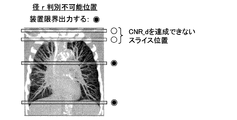
さらに、前記コントラストノイズ比算出手段で算出したコントラストノイズ比を実現できないスライス位置を前記表示手段に強調表示する。 Further, a slice position where the contrast noise ratio calculated by the contrast noise ratio calculating means cannot be realized is highlighted on the display means.
前記コントラストノイズ比判断手段において前記コントラストノイズ比算出手段で算出したコントラストノイズ比が全スライス位置に適用不可能と判断した場合に、前記指定したスライス位置の画像ノイズ標準偏差予測値が全スライス位置に適用可能かの判断をする全スライス位置適用判断手段と、この手段で全スライス位置に適用可能と判断した場合に、スライス位置に依らず前記所望スライス位置における画像ノイズ標準偏差予測値を満たす第2の管電流時間積を算出する第2の管電流時間積算出手段と、前記被検体のスライス位置毎のサイズと前記指定した所望スライス位置における被検体サイズとを比較する被検体サイズ比較手段とを備え、前記管電流時間積補正係数算出手段および前記管電流時間積補正手段は、前記被検体サイズ比較手段において、指定した所望スライス位置における被検体サイズがスキャン位置における被検体サイズと同等以下と判断された場合は、前記第2の管電流時間積における、管電圧に依らずコントラストノイズ比を概一定にするための管電流時間積補正係数を算出し、前記第2の管電流時間積を前記補正係数により補正し、前記管電圧算出手段が算出した管電圧および前記管電流時間積補正手段で補正した管電流時間積をX線条件とする。 When it is determined that the contrast noise ratio calculated by the contrast noise ratio calculating unit is not applicable to all slice positions in the contrast noise ratio determining unit, the predicted image noise standard deviation value at the specified slice position is set to all slice positions. All slice position application determining means for determining whether or not it is applicable, and when this means determines that it can be applied to all slice positions, the second satisfying the image noise standard deviation prediction value at the desired slice position regardless of the slice position Second tube current time product calculating means for calculating the tube current time product of the subject, and subject size comparing means for comparing the size of each slice position of the subject with the subject size at the designated desired slice position. The tube current time product correction coefficient calculation means and the tube current time product correction means comprise the object size When the comparing means determines that the object size at the designated desired slice position is equal to or smaller than the object size at the scan position, the contrast noise ratio is approximated regardless of the tube voltage in the second tube current time product. A tube current time product correction coefficient for making it constant is calculated, the second tube current time product is corrected by the correction coefficient, and the tube voltage calculated by the tube voltage calculation means and the tube current time product correction means The corrected tube current time product is taken as the X-ray condition.
前記第2の管電流時間積算出手段および前記管電流時間積補正係数算出手段の一例は以下のとおりである。 An example of the second tube current time product calculation means and the tube current time product correction coefficient calculation means is as follows.
(12)前記第2の管電流時間積算出手段は、第2の管電流時間積を、前記所望のスライス位置および前記診断対象の所定のサイズにおける画像ノイズ標準偏差値と管電流時間積の関係より求める手段である。 (12) The second tube current time product calculating means calculates the second tube current time product as a relationship between the desired slice position and the image noise standard deviation value at a predetermined size of the diagnosis target and the tube current time product. It is a means to seek more.
(13)前記管電流時間積補正係数算出手段は、前記補正係数を、前記診断対象の所定のサイズにおける管電圧と正規化コントラストノイズ比の関係より求める手段である。 (13) The tube current time product correction coefficient calculation means is a means for obtaining the correction coefficient from a relationship between a tube voltage and a normalized contrast noise ratio at a predetermined size of the diagnosis target.
前記被検体サイズ比較手段において、当該スライス位置における被検体サイズが前記指定したスライス位置における被検体サイズより大きいと判断された場合に、前記管電圧算出手段が算出した管電圧の条件下でスライス位置毎に前記所望スライス位置における画像ノイズ標準偏差予測値を満たす第3の管電流時間積を算出する第3の管電流時間積算出手段と、前記管電流時間積補正係数算出手段および前記管電流時間積補正手段は、前記第3の管電流時間積における、管電圧に依らずコントラストノイズ比を概一定にするための管電流時間積補正係数を算出し、前記第3の管電流時間積を前記補正係数により補正し、前記管電圧算出手段が算出した管電圧および前記管電流時間積補正手段で補正した管電流時間積をX線条件とする。 When the object size comparing means determines that the object size at the slice position is larger than the object size at the designated slice position, the slice position under the tube voltage condition calculated by the tube voltage calculating means Third tube current time product calculating means for calculating a third tube current time product satisfying the predicted image noise standard deviation value at the desired slice position, tube current time product correction coefficient calculating means, and tube current time The product correcting means calculates a tube current time product correction coefficient for making the contrast noise ratio substantially constant regardless of the tube voltage in the third tube current time product, and the third tube current time product is calculated as the third tube current time product. The tube voltage calculated by the tube voltage calculation means and the tube current time product corrected by the tube current time product correction means are set as the X-ray condition.
前記第3の管電流時間積算出手段および前記管電流時間積補正係数算出手段の一例は以下のとおりである。 An example of the third tube current time product calculating means and the tube current time product correction coefficient calculating means is as follows.
(14)前記第3の管電流時間積算出手段は、前記第3の管電流時間積を、前記所望のスライス位置および前記被検体のサイズにおける画像ノイズ標準偏差値と管電流時間積の関係より求める手段である。 (14) The third tube current time product calculating means calculates the third tube current time product from the relationship between the image slice standard deviation value and the tube current time product at the desired slice position and the size of the subject. It is a means to seek.
(15)前記管電流時間積補正係数算出手段は、前記被検体のサイズにおける管電圧と正規化コントラストノイズ比の関係より求める手段である。 (15) The tube current time product correction coefficient calculating means is a means for obtaining from a relationship between a tube voltage and a normalized contrast noise ratio in the size of the subject.
前記指定したスライス位置の画像標準偏差予測値が全スライス位置に適用できない場合に、前記指定したスライス位置における画像ノイズ標準偏差値を満たす第4の管電流時間積を算出する第4の管電流時間積算出手段と、該第4の管電流時間積を用いて前記指定したスライス位置における被曝線量とX線管電力を算出する指定スライス位置の被曝線量およびX線管電力算出手段と、この手段で算出したX線管電力が前記標準撮影条件であるX線管電力の基準値以下となる条件下で被曝線量を最小とする第2の管電圧を算出する第2の管電圧算出手段とを備え、前記第2の管電圧および前記第4の管電流時間積をX線条件とする。 Fourth tube current time for calculating a fourth tube current time product satisfying the image noise standard deviation value at the specified slice position when the image standard deviation prediction value at the specified slice position cannot be applied to all slice positions. A product calculating unit, a dose and X-ray tube power calculating unit for calculating a dose and an X-ray tube power at the specified slice position using the fourth tube current time product, Second tube voltage calculation means for calculating a second tube voltage that minimizes the exposure dose under the condition that the calculated X-ray tube power is not more than the reference value of the X-ray tube power that is the standard imaging condition. The second tube voltage and the fourth tube current time product are X-ray conditions.
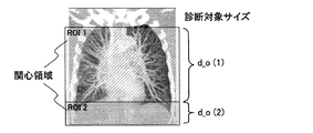
また、前記X線条件算出手段は、前記操作手段でスキャン領域を設定し、この領域内で複数の関心領域を設定する複数関心領域設定手段と、前記複数関心領域設定手段で設定した複数の関心領域毎に前記診断対象サイズ設定手段で診断対象サイズを設定し、かつ前記複数の診断対象サイズ内に存在する疾病の偽陽性率を設定する複数偽陽性率設定手段と、前記設定した複数の関心領域の診断対象サイズから当該診断対象を識別するためのコントラストノイズ比を算出するコントラストノイズ比算出手段と、前記被検体3次元モデルで前記設定した関心領域毎に画像ノイズ標準偏差値が最大になるスライス位置を算出するスライス位置算出手段と、想定コントラスト値と前記コントラストノイズ比算出手段で算出したコントラストノイズ比とから前記スライス位置算出手段で算出したスライス位置における画像ノイズ標準偏差値を算出する画像ノイズ標準偏差値算出手段と、該画像ノイズ標準偏差値算出手段で算出した画像ノイズ標準偏差値を実現するための管電流時間積を算出する管電流時間積算出手段と、該管電流時間積算出手段で算出した管電流時間積における管電圧に依らずコントラストノイズ比を概一定にするための管電流時間積補正係数を算出する管電流時間積補正係数算出手段と、前記管電流時間積算出手段で算出した管電流時間積を前記管電流時間積補正係数により補正する管電流時間積補正手段と、前記X線管で消費する電力が前記標準撮影条件であるX線管電力の基準値以下となる条件下で被曝線量を最小とする管電圧を算出する管電圧算出手段とを備え、前記管電圧算出手段が算出した管電圧および前記管電流時間積補正手段で補正した管電流時間積をX線条件とする。 The X-ray condition calculating means sets a scan region by the operation means, sets a plurality of regions of interest within the region, and a plurality of interests set by the plurality of region of interest setting means. A plurality of false positive rate setting means for setting a diagnostic target size for each region by the diagnostic target size setting means and setting a false positive rate for a disease existing in the plurality of diagnostic target sizes; and the plurality of set interests A contrast noise ratio calculating means for calculating a contrast noise ratio for identifying the diagnostic object from the diagnostic object size of the area, and the image noise standard deviation value is maximized for each region of interest set in the subject three-dimensional model. Slice position calculation means for calculating a slice position, an assumed contrast value, and a contrast noise ratio calculated by the contrast noise ratio calculation means. Image noise standard deviation value calculating means for calculating the image noise standard deviation value at the slice position calculated by the slice position calculating means, and a tube for realizing the image noise standard deviation value calculated by the image noise standard deviation value calculating means. Tube current time product calculating means for calculating the current time product, and a tube current time product correction coefficient for making the contrast noise ratio substantially constant regardless of the tube voltage in the tube current time product calculated by the tube current time product calculating means. Tube current time product correction coefficient calculation means for calculating the tube current time product correction means for correcting the tube current time product calculated by the tube current time product calculation means by the tube current time product correction coefficient, and the X-ray tube Tube voltage calculation means for calculating a tube voltage that minimizes the exposure dose under the condition that the power consumed in is less than the standard value of the X-ray tube power that is the standard imaging condition, The tube current time product corrected by the tube voltage voltage calculating means to calculate and the tube current time product correction means are assumed as the X-ray condition.
前記管電流時間積算出手段および前記管電流時間積補正係数算出手段の一例は以下のとおりである。 An example of the tube current time product calculation means and the tube current time product correction coefficient calculation means is as follows.
(16)前記管電流時間積算出手段は、前記被検体サイズにおける画像ノイズ標準偏差値と管電流時間積の関係より求める手段である。 (16) The tube current time product calculating means is a means for obtaining the relationship between the image noise standard deviation value and the tube current time product in the subject size.
(17)前記管電流時間積補正係数算出手段は、前記被検体サイズにおける管電圧と正規化コントラストノイズ比の関係より求める手段である。 (17) The tube current time product correction coefficient calculating means is a means for obtaining from the relationship between the tube voltage and the normalized contrast noise ratio in the subject size.
また、前記X線条件算出手段は、前記診断対象サイズ設定手段で設定した前記被検体の診断対象における真陽性率と偽陽性率とを設定する真陽性率および偽陽性率設定手段と、前記設定した診断対象のサイズから当該診断対象を識別するためのコントラストノイズ比を算出するコントラストノイズ比算出手段と、想定コントラスト値と前記コントラストノイズ比算出手段で算出したコントラストノイズ比とを満たす画像ノイズ標準偏差値を、特定スライス位置範囲内にあるスライス面毎に算出する画像ノイズ標準偏差値算出手段と、前記標準撮影条件として設定された管電圧において、スライス面毎の診断対象サイズで前記画像ノイズ標準偏差値を満たす管電流時間積を算出する管電流時間積算出手段とを備え、前記設定された管電圧および前記管電流時間積算出手段で算出された管電流時間積をX線条件とする。 In addition, the X-ray condition calculation unit includes a true positive rate and a false positive rate setting unit that sets a true positive rate and a false positive rate in the diagnosis target of the subject set by the diagnosis target size setting unit, and the setting A contrast noise ratio calculating means for calculating a contrast noise ratio for identifying the diagnosis object from the size of the diagnosis object, and an image noise standard deviation satisfying the assumed contrast value and the contrast noise ratio calculated by the contrast noise ratio calculation means Image noise standard deviation value calculation means for calculating a value for each slice plane within a specific slice position range, and the image noise standard deviation at a diagnosis target size for each slice plane in the tube voltage set as the standard imaging condition Tube current time product calculating means for calculating a tube current time product satisfying the value, and the set tube voltage and The tube current time product calculated by the serial tube current time product calculating means are assumed as the X-ray condition.
本発明によれば、被検体のスキャノグラム投影データを解析して被検体の3次元モデルを生成し、被検体の診断対象のサイズと被検体3次元モデルと予め設定してある標準撮影条件とから診断対象を識別するコントラストノイズ比を得るためのX線条件を算出し、この算出したX線条件でスキャンする構成としたので、診断対象を識別するために適切なCNRを達成し得るX線条件を決定できる。その結果、診断に必要十分な画質の断層画像を得るX線CT装置を提供することができる。 According to the present invention, the scanogram projection data of the subject is analyzed to generate a three-dimensional model of the subject, and the diagnosis target size of the subject, the three-dimensional model of the subject, and standard imaging conditions set in advance are determined. Since the X-ray condition for obtaining the contrast noise ratio for identifying the diagnosis object is calculated and scanning is performed under this calculated X-ray condition, the X-ray condition that can achieve an appropriate CNR for identifying the diagnosis object Can be determined. As a result, it is possible to provide an X-ray CT apparatus that obtains a tomographic image with sufficient image quality necessary for diagnosis.
以下、添付図面に従って本発明のX線CT装置の好ましい実施の形態について詳細に説明する。
なお、本発明は、診断対象を識別するために適切なコントラストノイズ比を得るためのX線条件をスキャン開始前に予め決定し、この決定したX線条件でスキャンするものであり、スキャン方式(アキシャルスキャン、螺旋スキャン)及びスライス型(シングルスライス、マルチスライス)のいずれにも適用可能であるが、ここでは、マルチスライス型螺旋スキャン方式のX線CT装置に適用した場合を例として説明する。Hereinafter, preferred embodiments of the X-ray CT apparatus of the present invention will be described in detail with reference to the accompanying drawings.
In the present invention, an X-ray condition for obtaining an appropriate contrast-to-noise ratio for identifying an object to be diagnosed is determined in advance before the start of scanning, and scanning is performed under this determined X-ray condition. The present invention can be applied to any of an axial scan, a spiral scan), and a slice type (single slice, multi-slice), but here, a case where it is applied to an X-ray CT apparatus of a multi-slice type spiral scan method will be described as an example.
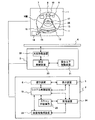
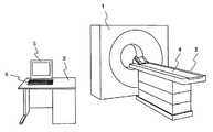
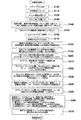
図2に本発明が適用されるX線CT装置の全体概観図、図1にその全体構成図を示す。
図2に示すX線CT装置は、被検体にX線を照射して前記被検体の透過X線データを収集し、この収集したX線データを再構成演算して断層像を得るもので、被検体にX線を照射して被検体を透過したX線データを収集するスキャナガントリ1と、被検体を載置する移動可能な天板4を備えた寝台2と、各種動作設定を行うと共に収集したX線データに基づいてX線断層像を再構成し表示する操作装置6と表示装置5等を備えた操作卓3とにより構成される。FIG. 2 is an overall overview diagram of an X-ray CT apparatus to which the present invention is applied, and FIG.
The X-ray CT apparatus shown in FIG. 2 collects transmission X-ray data of the subject by irradiating the subject with X-rays, and obtains a tomographic image by reconstructing the collected X-ray data. A
スキャナガントリ1は、図1に示すように、X線制御装置7によって制御されるX線を発生するX線管8を有し、該X線管8から放射されたX線はコリメータ制御装置9によって制御されるコリメータ10により、例えば角錐形のX線ビーム、すなわちコーンビームX線が被検体17に照射されて該被検体17を透過したX線はX線検出器11に入射する。
As shown in FIG. 1, the
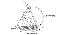
X線検出器11は、図3に示すようにチャネル方向と列方向に二次元的に配列された複数のX線検出素子18を有する。
このX線検出素子18は、例えばシンチレータとフォトダイオードとの組み合わせによって構成され、全体として円筒面状若しくはチャネル方向に関して折れ線状に湾曲したX線入射面を構成しており、例えばチャネル番号iは1〜1000程度、列番号jは1〜1000程度である。
X線検出器11におけるチャネルの配列方向に一致するコーンビームX線のチャネル方向の広がり角度、すなわちファン角度はαであり、またX線検出器11における列の配列方向に一致するコーンビームX線の列方向広がりの角度、すなわちコーン角度はγである。
X線検出器11にはデータ収集装置12が接続され、このデータ収集装置12はX線検出器11の個々のX線検出素子18の検出データを収集する。As shown in FIG. 3, the
The
The cone beam X-ray spread angle in the channel direction corresponding to the channel arrangement direction in the
A
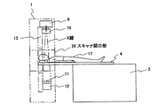
上記のX線制御装置7からデータ収集装置12までの構成要素はスキャナガントリ1の回転板13に搭載され、この回転板13は回転制御装置14によって制御される回転板駆動装置15からの駆動力が駆動力伝達系16により伝達されて被検体17の周囲を回転する。
The components from the
図1に示す被検体17を載置する移動可能な天板4を備えた寝台2は、寝台制御装置20によって寝台上下移動装置21を制御して適切な寝台高さにすると共に、前記寝台制御装置20によって天板移動装置22を制御して天板4を前後に移動させ、被検体17をスキャナガントリ1のX線照射空間(開口部)26に搬入および搬出するように構成されている。
The
このように構成されたスキャナガントリ1において、図4に示すように、寝台2の天板4に載置された被検体17がスキャナガントリ1の開口部26に搬入された後、コリメータ10の開口幅によりコーン角度γを調整したコーンビームX線を被検体17に照射すると、コーンビームX線を照射された被検体17のX線像はX線検出器11に投影され、X線検出器11によって被検体17を透過したX線が検出される。
In the
図1に示す前記操作卓3は、本発明によるX線CT装置のシステム全体を制御するシステム制御装置19を備え、このシステム制御装置19には、スキャナガントリ1と寝台2が接続されている。
すなわち、このシステム制御装置19により、スキャナガントリ1内のX線制御装置7、コリメータ制御装置9、データ収集装置12、回転制御装置14及び寝台2内の寝台制御装置20が制御される。The
That is, the
データ収集装置12で収集されたデータは、システム制御装置19の制御によって画像再構成装置23に入力される。
この画像再構成装置23は、スキャノグラム撮影時にはデータ収集装置12が収集したスキャノグラム投影データ(被検体透視データ)を用いてスキャノグラム画像を作成し、スキャン時にはデータ収集装置12が収集した複数ビューの投影データを用いてCT画像再構成を行う。The data collected by the
This
画像再構成装置23で作成されたスキャノグラム画像及び再構成されたCT画像や、各種データ、及びX線CT装置の機能を実現するためのプログラム等は、システム制御装置19に接続されている記憶装置24に格納されている。
記憶装置24には、標準撮影条件も記憶される。標準撮影条件とは、被検体17の体格や撮影部位で推奨される撮影条件を意味する。さらに後述するスキャン計画装置25の計算に必要なデータ等も保存される。
また、システム制御装置19には、表示装置5と操作装置6がそれぞれ接続され、表示装置5は、画像再構成装置23から出力される再構成画像やシステム制御装置19が取り扱う種々の情報を表示する。A storage device connected to the
The
Further, the
前記操作装置6は、操作者によって操作され、各種の指示や情報等をシステム制御装置19に入力する入力手段を備えている。
そして、操作者は、前記表示装置5および操作装置6を使用して対話的に本発明によるX線CT装置を操作する。The
The operator interactively operates the X-ray CT apparatus according to the present invention using the
さらに、システム制御装置19には、本発明の要部であるスキャン計画装置25が接続されており、このスキャン計画装置25は、操作者が前記操作装置6を使用して入力した指示と前記記憶装置24から読み出したスキャノグラム画像を用いて撮影条件をスキャン開始前に予め決定するものである。
すなわち、記憶装置24から読み出されたスキャノグラム画像が表示装置5に表示され、操作者は表示された被検体スキャノグラム画像上で操作装置6を用いてCT画像再構成位置(以下、スライス位置という)の座標を指定することにより、スライス位置を設定することができ、ここで設定したスライス位置の情報は記憶装置24に保存されると共にX線量制御条件等を設定するために用いられる。Further, the
That is, the scanogram image read from the
本発明によるX線CT装置は、被検体のCT画像を取得するスキャンの前に、撮影条件を決定するために種々の準備操作を行う。
この準備操作は、被検体の撮影位置を設定するためのスキャノグラム画像の撮影と、この撮影で得られたスキャノグラムデータの解析と、それに基づく撮影条件としての最適な照射X線条件の決定などで、これらはシステム制御装置19の制御の下で行われる。The X-ray CT apparatus according to the present invention performs various preparatory operations for determining imaging conditions before a scan for acquiring a CT image of a subject.
This preparatory operation includes scanning of a scanogram image for setting the imaging position of the subject, analysis of scanogram data obtained by this imaging, and determination of optimal irradiation X-ray conditions as imaging conditions based thereon, etc. Thus, these are performed under the control of the
この準備操作に関与する主な構成要素としては、図1中のシステム制御装置19と、スキャン計画装置25と、操作装置6と、表示装置5と、X線管8と、X線検出器11等で、特に、スキャノグラムデータの解析、それに基づく撮影条件としての最適な照射X線条件の決定は、システム制御装置19に接続されたスキャン計画装置25の重要な機能である(撮影条件決定手段)。
The main components involved in this preparatory operation are the
この準備操作において、先ずスキャノグラム画像(スキャン範囲の計画を立てるために一方向から透視して得られる画像)を得るために操作装置6は、主としてX線管電圧(X線管8の陽極と陰極間に印加する電圧)、X線管電流(X線管8の陽極と陰極間に流れる電流)の設定値等のX線条件をシステム制御装置19に入力する。
そして、回転板13を回転させずに被検体17を載置した天板4と回転板13を前記被検体17の体軸に沿って相対移動させて、スキャノグラム画像の撮影を行い、スキャノグラム投影データ及びスキャノグラム画像データを記憶装置24に保存する。
スキャノグラム画像データは、画像再構成装置23の機能の一部を使用して、スキャノグラム投影データにチャネル方向およびビュー方向の2次元フィルタ処理を行って作成する。In this preparatory operation, first, in order to obtain a scanogram image (an image obtained by seeing through from one direction in order to plan a scan range), the
Then, the top plate 4 on which the subject 17 is placed without rotating the
The scanogram image data is created by performing a two-dimensional filter process in the channel direction and the view direction on the scanogram projection data using a part of the function of the
スキャン計画装置25は、スキャノグラム投影データを解析し、被検体の体軸に沿った任意の位置における推定断面を、例えば水に等価なX線吸収係数を持つ楕円断面としてモデル化する。
このモデルは、被検体の体軸に沿った位置(以下、z位置と記載)に依存して楕円断面の長軸長・短軸長が変化する3次元的なモデルとなる(以下、被検体3次元モデルと記載)。
この被検体3次元モデルのデータは記憶装置24に保存される。The
This model is a three-dimensional model in which the major axis length and minor axis length of the elliptical cross section change depending on the position along the body axis of the subject (hereinafter referred to as the z position) (hereinafter referred to as the subject). Described as a three-dimensional model).
The data of the subject three-dimensional model is stored in the
そして、スキャン計画装置25は、操作装置6から入力された診断対象サイズ、管電圧及び管電流設定値、X線コリメーション条件、スキャナ1回転あたりの時間(以下、スキャン時間と記載)、及びスキャン計画装置25が作成した被検体3次元モデルのデータを基にして、推奨する管電圧及び該管電圧でのスキャン中に被検体断面形状の変化に応じて経時的に変化する一連の管電流値、すなわち管電流の変化パターンを算出する。
上記機能を持つスキャン計画装置25は、本発明の重要な構成要素で、これらによりスキャン時の最適なX線条件を決定するものである(X線条件算出手段)。Then, the
The
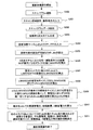
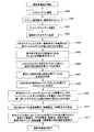
図5は上記最適なX線条件を決定するためのスキャン前に行なう準備操作の一連の動作フロー図で、以下、この動作フロー図を用いてX線条件を決定する工程について詳細に説明する。 FIG. 5 is a series of operation flow charts of the preparatory operations performed before scanning for determining the optimum X-ray condition. Hereinafter, the process of determining the X-ray conditions will be described in detail with reference to this operation flow chart.
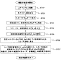
(1)スキャノグラム撮影(ステップS100)
被検体17のスキャノグラム画像を撮影する。被検体17のスキャノグラム画像を撮影する手順とスキャンにおいてCT画像を撮影する手順とは基本的には同じである。
このスキャノグラム投影データは、スキャナガントリ1の回転板13を回転させずに被検体17に対して一定方向、例えば被検体17の背面方向からX線を照射して、X線検出器11によって被検体17を透過したX線を検出し、この検出データを取り込むことによって得られる。(1) Scanogram photography (Step S100)
A scanogram image of the subject 17 is taken. The procedure for capturing a scanogram image of the subject 17 and the procedure for capturing a CT image in scanning are basically the same.
The scanogram projection data is obtained by irradiating the subject 17 with X-rays from a certain direction, for example, the back direction of the subject 17 without rotating the
X線検出器11で検出した検出データをデータ収集装置12で収集したスキャノグラム投影データは、このデータ収集装置12からシステム制御装置19を介して画像再構成装置23に送られ、該画像再構成装置23でスキャノグラム画像が作成され、表示装置5に表示される。
このとき得られるスキャノグラム画像は一定方向、例えば背面から正面へ透過するX線による像を正面方向から見たもので、このスキャノグラム画像は、スキャン時の被検体17のスライス位置(CT画像再構成位置)設定のために利用される。
スキャノグラム投影データは、スキャノグラム画像作成に用いられるだけでなく、本発明の特徴であるスキャンにおける最適なX線照射撮影条件決定のために利用される。Scanogram projection data obtained by collecting data detected by the
The scanogram image obtained at this time is an X-ray image transmitted from the back side to the front side, for example, from the front side. This scanogram image is the slice position of the subject 17 at the time of scanning (the CT image reconstruction position). ) Used for setting.
The scanogram projection data is used not only for creating a scanogram image but also for determining an optimum X-ray irradiation imaging condition in a scan that is a feature of the present invention.
(2)撮影条件の入力(ステップS110、S120、S130)
操作者が表示装置5に表示されたスキャノグラム画像を参照して操作装置6から撮影条件としての天板移動ピッチ、スキャン開始位置zs、スキャン終了位置zeを入力する。ここでzs≦zeと仮定して一般性を失わないので、以下においてzs≦zeとする。
これらの入力データを用いてスキャン計画装置25により、被検体17のCT画像撮影範囲とスライス位置zとX線管8の位相角(回転板13の位相角)βが決定される。
ここで、スキャン開始位置zs、スキャン終了位置zeは一連のスキャンで得られる最初のCT画像のz位置、最後のCT画像のz位置を各々意味している。(2) Input of shooting conditions (Steps S110, S120, S130)
The operator refers to the scanogram image displayed on the
By using these input data, the
Here, the scan start position zs and the scan end position ze mean the z position of the first CT image and the z position of the last CT image obtained by a series of scans, respectively.
(3)その他の撮影条件の入力(ステップS140)
操作者が操作装置6から撮影条件としての標準管電圧、標準管電流、スキャン時間、X線コリメーション条件、再構成フィルタ関数の種類、視野サイズ、スライス厚、ウィンドウ条件等を入力する。(3) Enter other shooting conditions (Step S140)
The operator inputs standard tube voltage, standard tube current, scan time, X-ray collimation condition, reconstruction filter function type, field size, slice thickness, window condition and the like as imaging conditions from the
(4)特定スライス位置範囲、診断対象サイズの入力(ステップS150)
操作者が操作装置6から、特に着目する撮影範囲の開始位置zssおよび終了位置zse、診断対象(例えば、造影した肝細胞がん)のサイズd_0を入力する。
ここで、zs≦zss≦zse≦zeである。zssの入力を省略した場合はzss=zs、zseの入力を省略した場合はzse=zeが自動設定される。また、診断対象のサイズd_0としては、例えば診断対象と等しい面積を持つ円の直径(等価直径)を入力する。(4) Input of specific slice position range and diagnosis target size (Step S150)
The operator inputs the start position zss and end position zse of the imaging range of particular interest and the size d_0 of the diagnosis target (eg, contrasted hepatocellular carcinoma) from the
Here, zs ≦ zss ≦ zse ≦ ze. If zss input is omitted, zss = zs is automatically set. If zse input is omitted, zse = ze is automatically set. For example, the diameter (equivalent diameter) of a circle having the same area as the diagnosis target is input as the size d_0 of the diagnosis target.
(5)スキャノグラムデータの解析及び被検体3次元モデルの生成(ステップS160、S170)
スキャン計画装置25でスキャノグラム投影データを解析して被検体17の被検体3次元モデルを生成する。
この被検体3次元モデルは、z位置に対応する被検体17の各断面を水に等価なX線吸収係数を持つ楕円断面として近似したもので、その近似方法については特許文献1や特開2001-276040号公報に開示されているので、ここではその説明を省略する。(5) Scanogram data analysis and object 3D model generation (steps S160 and S170)
The
This subject three-dimensional model is obtained by approximating each cross section of the subject 17 corresponding to the z position as an elliptical cross section having an X-ray absorption coefficient equivalent to water. -276040, the description thereof is omitted here.
(6)標準管電圧、標準管電流における画像SD予測値の算出(ステップS180)
標準管電圧xv_ref、標準管電流時間積(管電流値とスキャン時間との積)i_refを用いた場合に、スキャン開始位置zsからスキャン終了位置zeの範囲内の任意のスライス位置zにおいて得られるCT画像の画像SD値の予測値SD_ref(z,xv_ref,i_ref)を算出する(第1の画像SD予測値算出手段)。
この予測算出方法についても、特許文献1や特開2001-276040号公報に開示されている方法を各スライス位置zにおける断面モデル、標準管電圧xv_ref、標準管電流時間積i_refに対して用いればよいので、ここでは説明を省略する。(6) Calculation of predicted image SD value at standard tube voltage and standard tube current (step S180)
CT obtained at any slice position z within the range from the scan start position zs to the scan end position ze when using standard tube voltage xv_ref and standard tube current time product (product of tube current value and scan time) i_ref A predicted value SD_ref (z, xv_ref, i_ref) of the image SD value of the image is calculated (first image SD predicted value calculating means).
Also for this prediction calculation method, the method disclosed in
(7)特定スライス位置範囲における画像SD予測値の最大値及び当該スライス位置の算出(ステップS190)
前記ステップS180で予測したSD_ref(z,xv_ref,i_ref)の特定スライス位置範囲(zss≦z≦zse)における最大値MAX_SD_refと、画像SD値がMAX_SD_refとなるスライス位置(参照スライス位置)z_MAXSDを求める(画像SD予測値の最大値におけるスライス位置算出手段)。(7) Calculation of maximum value of predicted image SD in specific slice position range and corresponding slice position (step S190)
The maximum value MAX_SD_ref in the specific slice position range (zss ≦ z ≦ zse) of SD_ref (z, xv_ref, i_ref) predicted in step S180 and the slice position (reference slice position) z_MAXSD at which the image SD value becomes MAX_SD_ref are obtained ( (Slice position calculation means for the maximum image SD predicted value).
(8)診断対象識別可能なCNRの算出(ステップS200)
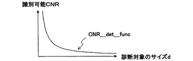
ステップS150で入力した診断対象サイズd_oから診断対象を識別可能なCNRを求める(コントラストノイズ比算出手段)。
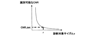
これは図6に示す診断対象サイズdと識別可能CNRとの関係の関数CNR_det_funcを予め実験により求めておき、次式により目的とする識別可能コントラストノイズ比CNR_detを求めることによって成される。
CNR_det=CNR_det_func(d_o) (式1)
ここで、関数CNR_det_funcは典型的には次式のように表される
CNR_det_func(x)≡a×x-b (式2)
ただし、a、bは実数であり、a>0、b>0である。(8) Calculation of CNR that can identify the diagnosis target (step S200)
A CNR capable of identifying the diagnosis target is obtained from the diagnosis target size d_o input in step S150 (contrast noise ratio calculation means).
This is achieved by obtaining a function CNR_det_func of the relationship between the diagnostic object size d and the identifiable CNR shown in FIG. 6 in advance by experiment, and obtaining the target identifiable contrast noise ratio CNR_det by the following equation.
CNR_det = CNR_det_func (d_o) (Formula 1)
Here, the function CNR_det_func is typically expressed as:
CNR_det_func (x) ≡a × xb (Formula 2)
However, a and b are real numbers, and a> 0 and b> 0.
なお、式2は多項式による表現も可能とする。
この場合、
CNR_det_func=a+b*x+c*x2+・・・+n*xn (式2’)
のように表される。
ただし、a, b, c, nは実数である。
in this case,
CNR_det_func = a + b * x + c * x 2 + ... + n * x n (Formula 2 ')
It is expressed as
However, a, b, c, and n are real numbers.
また診断対象サイズd_oと識別可能なCNRの関係は、表1のようにデータテーブルとして記憶装置に保持していても良いものとする。このデータテーブルを操作者に開示し、操作者が所望の変更を加えることも可能である。この場合、変更されたデータに基づき、離散的なデータをスプライン補間する等によって、最適な近似曲線が自動的に作成されるようにするのが望ましい。 Further, the relationship between the diagnosis target size d_o and the identifiable CNR may be held in the storage device as a data table as shown in Table 1. The data table can be disclosed to the operator, and the operator can make a desired change. In this case, it is desirable to automatically create an optimal approximate curve by spline interpolation of discrete data based on the changed data.

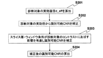
(9)識別可能なCNRをスライス厚およびウィンドウ条件に基づいて補正(ステップS201〜S204)
ここでは、ステップS200で算出した識別可能CNRを、ステップS140で設定したスライス厚およびウィンドウ条件の情報を基に補正する。具体的には、図7に示す手順により補正処理を行う。(9) Correct identifiable CNR based on slice thickness and window conditions (steps S201 to S204)
Here, the identifiable CNR calculated in step S200 is corrected based on the slice thickness and window condition information set in step S140. Specifically, the correction process is performed according to the procedure shown in FIG.
(9-1)ステップS201
スライス厚と診断対象サイズdとから診断対象実効径d_effを算出する。
これは診断対象を球とした場合にスライス厚が厚くなることにより、球の見かけ上のサイズが小さく見えるため、ここではその実効的なサイズを求める。典型的には以下の式により表される。スライス厚をSthickとすると、
A diagnosis target effective diameter d_eff is calculated from the slice thickness and the diagnosis target size d.
This is because, when the diagnosis target is a sphere, the apparent size of the sphere appears to be small due to an increase in the slice thickness, so the effective size is obtained here. Typically, it is represented by the following formula. If the slice thickness is Stick,
(9-2)ステップS202
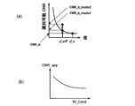
診断対象の実効径d_effに基づき、スライス厚による実効径の変化が識別可能CNRに及ぼす影響を補正する。図8(a)に示すように、識別可能CNRと診断対象のサイズ(径)との関係を示すグラフにおいて、診断対象のサイズがd_oからd_effに変わる、識別可能CNRも変わり、この時点での補正後の識別可能CNRは、CNR_d_modu1となる。(9-2) Step S202
Based on the effective diameter d_eff of the diagnosis target, the influence of the change in the effective diameter due to the slice thickness on the identifiable CNR is corrected. As shown in FIG. 8 (a), in the graph showing the relationship between the identifiable CNR and the size (diameter) of the diagnosis object, the size of the diagnosis object changes from d_o to d_eff, and the identifiable CNR also changes. The identifiable CNR after correction is CNR_d_modu1.
(9-3)ステップS203
スライス厚、ウィンドウ条件(ウィンドウ幅、ウィンドウレベル)が診断対象のコントラストに及ぼす影響を補正する。
これはスライス厚およびウィンドウ条件が変化した場合、診断対象の見かけ上のコントラストが変化し、識別可能CNRを適切に補正する必要があるためである。(9-3) Step S203
The influence of the slice thickness and window conditions (window width, window level) on the contrast of the diagnosis target is corrected.
This is because when the slice thickness and the window condition change, the apparent contrast of the diagnosis target changes, and the identifiable CNR needs to be appropriately corrected.
ウィンドウ条件(ウィンドウ幅、ウィンドウレベル:W_Cond)の変化に対応する「診断対象を識別可能な見かけ上のCNRの変化割合(CNR_app)」の関係の概略図を、図8(b)に示す。
典型的には式2および式2’において、CNR_det_funcをCNR_appに、xをW_Condに置き換えた式により表される。よって、ウィンドウ条件を考慮した場合、補正後の識別可能CNRをCNR_d_modu2とすると、
CNR_d_modu2=CNR_d_modu1*CNR_app
となる。
Window condition (window width, window level: W_Cond) a schematic diagram of a relationship corresponding to changes in the "rate of change of CNR on identifiable diagnostic object appearance (CNR_app)", shown in Figure 8 (b).
Typically, in
CNR_d_modu2 = CNR_d_modu1 * CNR_app
It becomes.
(9-4)ステップS204
以上、ステップS201〜S203の手順を踏むことにより、スライス厚やウィンドウ条件の影響を考慮した補正後の識別可能CNR(CNR_d_modu2)を得ることができる。
なお、上記ステップS201〜S204による識別可能CNRの補正は、本実施の形態において必須ではないが、スライス厚およびウィンドウ条件を考慮した補正を行なうことにより、より精度の高いX線条件設定を行なうことができる。以下、参照する識別可能コントラストノイズ比CNR_detは、上述した補正後の識別可能コントラストノイズ比を含む。(9-4) Step S204
As described above, the identifiable CNR (CNR_d_modu2) after correction in consideration of the influence of the slice thickness and the window condition can be obtained by following the procedure of steps S201 to S203.
Note that correction of the identifiable CNR in steps S201 to S204 is not essential in the present embodiment, but more accurate X-ray condition setting is performed by performing correction in consideration of slice thickness and window conditions. Can do. Hereinafter, the identifiable contrast noise ratio CNR_det to be referred to includes the identifiable contrast noise ratio after correction described above.
(10)標準管電圧で実現すべき画像SD基準値の算出(ステップS210)
予め記憶装置24に格納してある診断対象の標準管電圧xv_refにおける想定コントラスト値C_oとステップS200で求めたCNR_detとから、標準管電圧で実現すべき画像SD値の基準値であるSD_xv_refを次式により求める(第1の画像SD基準値算出手段)。
SD_xv_ref=C_o/CNR_det (式3)(10) Calculation of image SD reference value to be realized with standard tube voltage (step S210)
SD_xv_ref, which is a reference value of the image SD value to be realized with the standard tube voltage, is calculated from the assumed contrast value C_o in the standard tube voltage xv_ref to be diagnosed stored in the
SD_xv_ref = C_o / CNR_det (Formula 3)
(11)SD_xv_refを実現する管電流時間積i_ta(z_MAXSD)の算出(ステップS220)
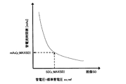
参照スライス位置z_MAXSDにおける標準管電圧xv_refのもとでの画像SD値であるSD_xv_refを実現するための管電流時間積i_ta(z_MAXSD)を次式によって求める(第1の管電流時間積算出手段)。
i_ta(z_MAXSD)=i_ref×(MAX_SD_ref/SD_xv_ref)2 (式4)(11) Calculation of tube current time product i_ta (z_MAXSD) that realizes SD_xv_ref (step S220)
A tube current time product i_ta (z_MAXSD) for realizing SD_xv_ref which is an image SD value under the standard tube voltage xv_ref at the reference slice position z_MAXSD is obtained by the following equation (first tube current time product calculating means).
i_ta (z_MAXSD) = i_ref × (MAX_SD_ref / SD_xv_ref) 2 (Formula 4)
(12)画像SD≦上限値SD_ULIMとなる管電圧xv_a及びスライス位置z_MAXSDにおける予測画像SD値SD_xv_aの算出(ステップS230)
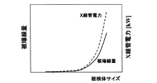
識別対象以外の部分の画質を考慮し、(式4)で算出した管電流時間積i_ta(z_MAXSD)での画像SDが上限値SD_ULIM以下となるような管電圧xv_aを求める。画像SDの上限値SD_ULIMは、適切な値を予め操作装置から入力しておく。或いは推奨される値をデフォルトで記憶装置24に設定しておいてもよい。
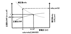
ここで、管電流一定のもとでは管電圧によらず造影対象のCNRが略一定に保たれることがわかっているため、管電圧の変更は造影対象の診断に悪影響を与えない。
そこで、管電圧xv_aの算出は、画像SD値の予測機能を用い、実験データ他に基づいて求めた図9に示すスライス位置z_MAXSD、管電流時間積i_ta(z_MAXSD)のもとでの管電圧と画像SDとの関係を用いて、次式を満たす最低の管電圧xv_aを求める。(第1の管電圧を算出する手段)。
SD_ULIM≧SD_func(xv_a) (式5)
この時、スライス位置z_MAXSDにおいて予測される画像SD値をSD_xv_aとする。なお管電圧と画像SDとの関係は典型的には次式のように表される。
SD_func(x)≡c×x-g (式6)
ただし、c、gは実数であり、c>0、g>0である。(12) Calculation of predicted image SD value SD_xv_a at tube voltage xv_a and slice position z_MAXSD satisfying image SD ≦ upper limit value SD_ULIM (step S230)
The tube voltage xv_a is determined such that the image SD at the tube current time product i_ta (z_MAXSD) calculated by (Equation 4) is not more than the upper limit value SD_ULIM in consideration of the image quality of the portion other than the identification target. For the upper limit value SD_ULIM of the image SD, an appropriate value is input in advance from the operation device. Alternatively, recommended values may be set in the
Here, since it is known that the CNR of the contrast target is kept substantially constant regardless of the tube voltage under a constant tube current, the change of the tube voltage does not adversely affect the diagnosis of the contrast target.
Therefore, the calculation of the tube voltage xv_a uses the prediction function of the image SD value, and the tube voltage based on the slice position z_MAXSD and the tube current time product i_ta (z_MAXSD) shown in FIG. Using the relationship with the image SD, the lowest tube voltage xv_a that satisfies the following equation is obtained. (Means for calculating the first tube voltage).
SD_ULIM ≧ SD_func (xv_a) (Formula 5)
At this time, the image SD value predicted at the slice position z_MAXSD is defined as SD_xv_a. The relationship between the tube voltage and the image SD is typically expressed as the following equation.
SD_func (x) ≡c × x -g (Formula 6)
However, c and g are real numbers, and c> 0 and g> 0.
(13)管電圧xv_a、管電流時間積i_ta(z_MAXSD)時の画像SD予測値の算出(ステップS240)
画像SD予測機能により、各スライス位置zにおいて管電圧xv_a、管電流時間積i_ta(z_MAXSD)を用いた場合に得られるCT画像の画像SD値、SD_ref(z,xv_a,i_ta(z_MAXSD))を予測する(第2の画像SD予測値算出手段)。(13) Calculation of predicted image SD value at tube voltage xv_a and tube current time product i_ta (z_MAXSD) (step S240)
Image SD prediction function predicts the image SD value, SD_ref (z, xv_a, i_ta (z_MAXSD)) of the CT image obtained when the tube voltage xv_a and tube current time product i_ta (z_MAXSD) are used at each slice position z (Second image SD predicted value calculation means).
(14)スライス位置zにおける画像SD値SD_xv_aを実現するための管電流時間積i_r(z)の算出(ステップS250)
各スライス位置zにおける管電圧xv_aのもとでスライス位置z_MAXSDにおいて予測される画像SD値SD_xv_aとするための管電流時間積i_r(z)を次式によって求める(第2の管電流時間積算出手段)。
i_r(z)=i_ta(z_MAXSD)×(SD_ref(z,xv_a,i_ta(z_MAXSD))/SD_xv_a)2
こうして求めた管電流時間積i_r(z)および管電圧xv_aが、スキャン計画装置25で算出された管電流時間積および管電圧の推奨条件となる。(14) Calculation of tube current time product i_r (z) for realizing image SD value SD_xv_a at slice position z (step S250)
A tube current time product i_r (z) for obtaining an image SD value SD_xv_a predicted at the slice position z_MAXSD under the tube voltage xv_a at each slice position z is obtained by the following equation (second tube current time product calculating means: ).
i_r (z) = i_ta (z_MAXSD) × (SD_ref (z, xv_a, i_ta (z_MAXSD)) / SD_xv_a) 2
The tube current time product i_r (z) and the tube voltage xv_a thus obtained are the recommended conditions for the tube current time product and the tube voltage calculated by the
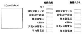
(15)管電圧、管電流と被曝線量、画像SD予測値との関係の表示(ステップS260)
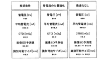
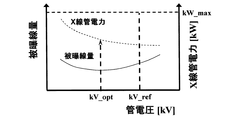
上記推奨条件およびそれ以外の条件で撮影した場合の、被曝線量(CTDI)、画像SD値、診断対象の識別可能サイズ等の予想値を計算し、それを操作者に対する選択肢として表示する。例えば、以下の選択肢<1>〜<3>の各々につき、図10に示すように、管電圧、平均管電流(管電流時間積をスキャン時間で除した値)、被曝線量(CTDI)、画像SD値、診断対象の識別可能サイズ等の予想値を表示し(評価指標の予想値表示手段)、この中で選択肢<1>が推奨条件であることを明示する。
なお診断対象の識別可能サイズについては、(式1)に記載した関数CNR_det_funcの逆関数を用いて算出することができる。
<1>管電圧xv_a、管電流時間積i_r(z)を使用する場合(推奨条件)
<2>標準管電圧xv_ref、管電流時間積i_r(z)を使用する場合(管電流のみ最適化)
<3>標準管電圧xv_ref、標準管電流時間積i_refを使用する場合(最適化なし)(15) Display of relationship between tube voltage, tube current and exposure dose, image SD predicted value (step S260)
Estimated values such as exposure dose (CTDI), image SD value, and identifiable size of the diagnostic target when the image is taken under the above recommended conditions and other conditions are calculated and displayed as options for the operator. For example, for each of the following options <1> to <3>, as shown in FIG. 10, the tube voltage, the average tube current (the value obtained by dividing the tube current time product by the scan time), the exposure dose (CTDI), the image Display expected values such as the SD value and the identifiable size of the diagnosis target (predicted value display means of evaluation index), and clearly indicate that option <1> is the recommended condition.
The identifiable size of the diagnosis target can be calculated using the inverse function of the function CNR_det_func described in (Equation 1).
<1> When using tube voltage xv_a and tube current time product i_r (z) (recommended condition)
<2> When using standard tube voltage xv_ref and tube current time product i_r (z) (only tube current is optimized)
<3> When using standard tube voltage xv_ref and standard tube current time product i_ref (no optimization)
上記<1>、<2>、<3>の選択肢において、<1>は管電圧、管電流ともに最適化した場合、<2>は管電流のみ最適化し、管電圧は標準的な値を使用する場合、<3>は管電圧及び管電流も最適化せずに、標準的な撮影条件を使用する場合である。 In the above options <1>, <2>, and <3>, <1> optimizes both the tube voltage and tube current, <2> optimizes only the tube current, and uses standard values for the tube voltage When <3> is selected, standard tube conditions and tube currents are not optimized and standard imaging conditions are used.
上記のように表示することによって、各々のメリットとデメリットが良く分かるようになり、操作者は前記メリットとデメリットを考慮して撮影条件を選択することができる。
通常は、本発明の目的である診断対象を識別するために適切なCNRを達成するためのX線条件を求めて、このX線条件でスキャンする場合は<1>が最適であるが、読影医等の判断で<1>以外を選ぶこともあり、そのような場合でも、その結果得られる画質等について予測値を示しておく方が判断の一助となる。By displaying as described above, the respective merits and demerits can be well understood, and the operator can select the photographing conditions in consideration of the merits and demerits.
Normally, when obtaining an X-ray condition for achieving an appropriate CNR for identifying a diagnostic object, which is the object of the present invention, and scanning under this X-ray condition, <1> is optimal. In some cases, doctors may select something other than <1>. Even in such a case, it is helpful to indicate the predicted value for the image quality obtained as a result.
(16)撮影条件の選択(ステップS270)
操作者が前記ステップS260で示された選択肢から最も適切な条件を選択する。
前記条件の選択は、例えば図10に示す条件を表示装置5に表示し、この表示された条件の中から使用する条件を操作装置6の入力装置、例えばマウスでクリックして選択する(X線条件選択手段)。(16) Selecting shooting conditions (Step S270)
The operator selects the most appropriate condition from the options shown in step S260.
For the selection of the conditions, for example, the conditions shown in FIG. 10 are displayed on the
以上のようにして、診断対象を識別するために適切なCNRを達成し得る撮影条件を決定することができる。
なお、診断対象を最小限の被曝線量で識別可能とするには<1>が最適であるが、若干被曝線量が増大しても<1>より画像SD値が小さい画像にしたい場合は<2>を選択し、あるいは経験的に慣れている標準条件でスキャンするのが最も適切と考える場合は<3>を選択することになる。
ただし、<3>は適切なCNRを達成できない場合が考えられるので、表示された識別可能サイズが入力した診断対象サイズより大きくなってしまう場合は、改めて<1>や<2>を選択すれば良い。As described above, imaging conditions that can achieve an appropriate CNR for identifying a diagnosis target can be determined.
Note that <1> is optimal for identifying the diagnosis target with the minimum exposure dose, but <2> if you want an image with a smaller SD value than <1> even if the exposure dose increases slightly. Select <3> if you think that it is most appropriate to select> or scan using standard conditions that you are familiar with.
However, since <3> may not be able to achieve an appropriate CNR, if the displayed identifiable size is larger than the entered diagnostic target size, you can select <1> or <2> again. good.
このように、実際に撮影条件を決定するには読影医の経験等に基づいて決定する場合もあるので、これを考慮して上記のように使用目的に応じて撮影条件を選択できるように配慮することにより柔軟なシステムにすることができる。 In this way, the actual imaging conditions may be determined based on the interpretation doctor's experience, etc., so that it is possible to select the imaging conditions according to the purpose of use as described above. By doing so, a flexible system can be obtained.
以上のようにして決定された撮影条件は記憶装置24に保存され、スキャン時に被検体17の撮影部位に応じてシステム制御装置19によって順次読み出されて、X線制御装置7を介してスキャン中の撮影条件(管電圧、管電流)を制御する。
The imaging conditions determined as described above are stored in the
上記機能及び処理を実行するシステム制御装置19、スキャン計画装置25、操作装置6等の装置は、プロセッサ、コンピュータ、メモリ、記憶装置、レジスタ、タイミング制御、割り込み、通信インタフェイス、及び入力/出力信号インタフェイス等の組み合わせによりコンピュータ・プログラムに応じて動作する構成とすることにより具現化可能である。
The
以上、実施形態例を参照して本発明について説明したが、本発明は上記実施形態に限定されるものではなく、本発明の主旨を逸脱しない範囲で種々変更可能であることは言うまでもない。 The present invention has been described with reference to the exemplary embodiments. However, the present invention is not limited to the above-described embodiments, and needless to say, various modifications can be made without departing from the gist of the present invention.
上記に説明した如く、本発明のX線CT装置は、スキャン計画装置25により、被検体17のスキャノグラム投影データから被検体17の3次元モデルを生成するスキャノグラム解析及び被検体3次元モデル生成機能や、識別対象のサイズから診断に必要なCNRを算出し、被検体17の3次元モデルから被検体の撮影部位に応じた適切な撮影条件を算出して設定する最適撮影条件設定機能を備えているので、適切な画質の被検体画像を得るためのX線CT検査を容易に提供することが可能となる。
As described above, the X-ray CT apparatus of the present invention uses the
次に、別の好ましい5つの実施形態について図11以降の図面を用いて説明する。なお、前記別の好ましい5つの実施形態と図5の動作フローにより説明した実施形態とを区別するために、上記図5を第1の実施形態とし、別の好ましい5つの実施形態を説明順にそれぞれ第2の実施形態、第3の実施形態、第4の実施形態、第5の実施形態、第6の実施形態とする。 Next, five other preferred embodiments will be described with reference to FIG. 11 and subsequent drawings. In order to distinguish the other five preferred embodiments from the embodiment described with reference to the operation flow of FIG. 5, FIG. 5 is referred to as the first embodiment, and the other five preferred embodiments are described in the order of explanation. The second embodiment, the third embodiment, the fourth embodiment, the fifth embodiment, and the sixth embodiment are used.
《第2の実施形態》
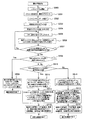
図11は、第2の実施形態における上記最適なX線条件を決定するためのスキャン前に行なう準備操作の一連の動作フロー図で、以下、この動作フロー図を用いてX線条件を決定する工程について詳細に説明する。
本実施形態は、(a)識別可能CNRの算出に際し、診断対象のサイズに加えて、真陽性率および偽陽性率を用いる点、および(b)予め求めておいた画像SDと管電流時間積mAsの関係を用いて識別可能CNRを実現する管電流時間積mAsを求める点、および(c)求めた管電流時間積mAsを管電圧に依らずCNRを概一定にするように補正する点が、主として第1の実施形態と異なっている。(a)を採用することにより、読影医の読影能力を考慮した識別可能CNRに基づき推奨撮影条件を算出することができる。<< Second Embodiment >>
FIG. 11 is a series of operation flowcharts of preparatory operations performed before scanning for determining the optimum X-ray condition in the second embodiment. Hereinafter, the X-ray conditions are determined using this operation flowchart. The process will be described in detail.
In this embodiment, in calculating (a) the identifiable CNR, in addition to the size of the diagnosis object, the true positive rate and the false positive rate are used, and (b) the image SD and the tube current time product obtained in advance. The point of calculating tube current time product mAs that realizes identifiable CNR using the relationship of mAs, and (c) the point of correcting the calculated tube current time product mAs so that CNR is almost constant regardless of tube voltage. This is mainly different from the first embodiment. By adopting (a), it is possible to calculate the recommended imaging condition based on the identifiable CNR considering the interpretation ability of the interpretation doctor.
(1)スキャノグラム撮影(ステップS300)
被検体17のスキャノグラム画像を撮影する。このスキャノグラム画像の撮影は第1の実施形態と同様であるので、その詳細については省略する。(1) Scanogram photography (Step S300)
A scanogram image of the subject 17 is taken. Since the scanogram image is taken in the same manner as in the first embodiment, the details thereof are omitted.
(2)スキャン領域設定、撮影条件の入力(ステップS301)
この処理は、第1の実施形態のステップS110、S120、S130およびS140と同じで、操作者がスキャノグラム画像を参照して操作装置6から診断対象を含んだ撮影領域(スキャン開始位置zs、スキャン終了位置ze)を設定する。
ここで、スライス位置の撮影条件として、スライス厚、天板移動ピッチ、スキャン時間、標準管電圧、標準管電流、X線コリメーション条件、再構成フィルタ関数の種類、視野サイズ、ウィンドウ条件等を入力する。(2) Scan area setting and shooting condition input (step S301)
This process is the same as steps S110, S120, S130, and S140 of the first embodiment, in which the operator refers to the scanogram image and includes an imaging region (scan start position zs, scan end) that includes a diagnosis target from the
Here, the slice thickness, the top plate movement pitch, the scan time, the standard tube voltage, the standard tube current, the X-ray collimation condition, the type of reconstruction filter function, the field size, the window condition, etc. are input as the imaging conditions for the slice position. .
(3)スキャノグラムデータ解析(ステップS302)および被検体3次元モデル生成(ステップS303)
第1の実施形態のS160、S170と同様に、スキャン計画装置25でスキャノグラム投影データを解析して被検体17の被検体3次元モデルを生成する。(3) Scanogram data analysis (step S302) and subject three-dimensional model generation (step S303)
Similarly to S160 and S170 of the first embodiment, the
(4)診断対象サイズd_oおよびTPF、FPFの入力(ステップS304)
操作装置6の入力装置から診断対象となるもののサイズ(例えば造影された肝細胞ガン)d_oを入力して設定する。
さらに、操作装置6の入力装置から操作者が診断の際の目安となる真陽性率(診断対象に存在する疾病が正しいと判断する確率:True Positive Fraction、以下「TPF」と記す)と偽陽性率(診断対象に疾病が存在しないにもかかわらず誤って存在すると判断する確率:False Positive Fraction、以下「FPF」と記す)とを操作装置6の入力装置から入力して設定する(真陽性率および偽陽性率設定手段)。
診断対象のサイズは、例えば診断対象と等しい面積を持った円の直径r(円等価直径)とする。(4) Input of diagnosis target size d_o, TPF, FPF (step S304)
The size (for example, contrasted hepatocellular carcinoma) d_o of an object to be diagnosed is input and set from the input device of the
In addition, the true positive rate (probability to determine that the disease existing in the diagnosis target is correct: True Positive Fraction, hereinafter referred to as “TPF”) is a false positive, which is a guideline for the diagnosis from the input device of the
The size of the diagnosis target is, for example, the diameter r (circle equivalent diameter) of a circle having the same area as the diagnosis target.
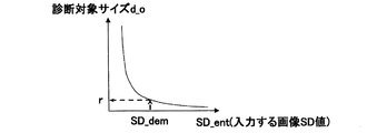
(5)診断対象の識別が可能なCNR_detの算出(ステップS305)
ステップS304で操作者が入力した診断対象のサイズd_oから診断対象を識別可能なCNR_detを求める(コントラストノイズ比算出手段)。
識別可能なCNR_detは、図12に示す診断対象サイズd_oと識別可能なCNRとの関係図(診断対象サイズと識別可能なコントラストノイズ比との関係)と、図13(a)に示すFPFとTPFとの関係図(真陽性率と偽陽性率との関係)および図13(b)に示す識別可能なCNRとFPFとの関係図(識別可能なコントラストノイズ比と偽陽性率との関係)を用いて算出する。(5) Calculation of CNR_det that can identify the diagnosis target (step S305)
In step S304, CNR_det that can identify the diagnosis target is obtained from the size d_o of the diagnosis target input by the operator (contrast noise ratio calculation means).
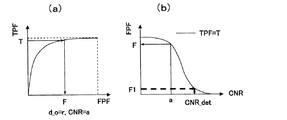
The identifiable CNR_det is a relationship diagram between the diagnosis target size d_o and the identifiable CNR shown in FIG. 12 (relationship between the diagnosis target size and the identifiable contrast noise ratio), and the FPF and TPF shown in FIG. And the relationship between the identifiable CNR and FPF shown in FIG. 13B (the relationship between the identifiable contrast noise ratio and the false positive rate). Use to calculate.
先ず、図12に示す診断対象サイズd_oと識別可能なCNRとの関係を得るためには、例えば操作者がTPF、FPF、d_oなどを入力することによって、後述の図13(a)に示すFPFとTPFとの関係および図13(b)に示す識別可能なCNRとFPFとの関係図を求める必要がある。 First, in order to obtain the relationship between the diagnostic object size d_o shown in FIG. 12 and the identifiable CNR, for example, when the operator inputs TPF, FPF, d_o, etc., the FPF shown in FIG. And the relationship between the identifiable CNR and the FPF shown in FIG.
図13(a)に示すFPFとTPFとの関係を表すROC曲線(receiver operating characteristic curve)は、診断対象サイズ毎にCNRを変化させた場合について、CNRが既知の画像を用いて予めROC解析を行って算出し、この結果を記憶装置24に格納しておく。
そして、図13(a)のROC曲線上で操作者がステップS304で入力したTPFの値がTである場合、例えば、d_o=r、CNR=aのROC曲線上からTPF=Tに対応するFPF=Fをスキャン計画装置25で算出する。同様にして異なるCNR毎のROC曲線で、TPF=Tに対するFPFを求め、図13(b)に示すCNR-FPF曲線を作成する。
その後、CNR−FPF曲線において、例えばFPF=F1におけるCNR_detが診断対象サイズrにおける識別可能なCNRとして算出される(図12に参照)。The ROC curve (receiver operating characteristic curve) representing the relationship between FPF and TPF shown in FIG. 13 (a) is obtained by performing ROC analysis in advance using an image with a known CNR when the CNR is changed for each diagnosis target size. The calculation is performed and the result is stored in the
If the TPF value input by the operator in step S304 on the ROC curve in FIG. 13A is T, for example, the FPF corresponding to TPF = T from the ROC curve with d_o = r and CNR = a. = F is calculated by the
Thereafter, in the CNR-FPF curve, for example, CNR_det at FPF = F1 is calculated as an identifiable CNR at the diagnosis object size r (see FIG. 12).
CNR−FPF曲線は、操作者がTPFを入力した時点で様々な診断対象サイズで作成されて記憶装置24に格納される。
ここで、さらにFPFの値を定めることによって、図12に示す様な診断対象サイズd_oと識別可能CNRとの関係図が作成される。
この図12の関係図を基に、操作者は該当する検査に対応する診断対象サイズd_oを入力することで、該診断対象サイズd_oに対応する識別可能なCNR_detを算出することができる。The CNR-FPF curve is created in various sizes to be diagnosed when the operator inputs the TPF and stored in the
Here, by further determining the FPF value, a relationship diagram between the diagnosis target size d_o and the identifiable CNR as shown in FIG. 12 is created.
Based on the relationship diagram of FIG. 12, the operator can calculate the identifiable CNR_det corresponding to the diagnosis target size d_o by inputting the diagnosis target size d_o corresponding to the corresponding examination.
なお、記憶装置24に格納してあるCNR毎のROC曲線は、読影者に応じて改変することも可能である。
このように、読影者に応じて改変する場合は、ROC解析を行うためのデータセットを記憶装置24に格納しておいても良いし、操作者が用意したものを使用しても良い。Note that the ROC curve for each CNR stored in the
As described above, when the modification is performed according to the interpreter, a data set for performing the ROC analysis may be stored in the
またステップS304において、TPFやFPFの入力は省略し、デフォルト値として、例えばTPF=0.95、FPF=0.05のような値を予め記憶装置24に格納しておいても良い。
さらにまた、診断対象サイズd_oの入力も省略可能である。この場合は、診断対象部位や撮影部位に応じて、例えば肝臓領域であればd_o=10mmという値を予め記憶装置24に格納しておき、読影者に応じて改変することも可能である。
なお、診断対象サイズd_oと識別可能CNRの関係は、典型的には上記(式2)と同様である。In step S304, input of TPF or FPF may be omitted, and values such as TPF = 0.95 and FPF = 0.05 may be stored in the
Furthermore, the input of the diagnostic object size d_o can be omitted. In this case, a value of d_o = 10 mm may be stored in advance in the
Note that the relationship between the diagnosis target size d_o and the identifiable CNR is typically the same as that in the above (Formula 2).
ここで、読影医が予め決まっている場合には、記憶装置24に格納してあるデータセットをステップS304以前に呼び出しておき、読影医のROC解析結果と(式2)を用いて、読影医が設定した診断対象サイズから導き出された識別可能なCNRを求める。
この結果、算出した(式2)の曲線と読影医の読影能力が完全に一致することで、より最適な識別可能なCNRの設定が可能になる。
この方法による識別可能なCNRの設定は、以下の実施形態(第3の実施形態、第4の実施形態および第5の実施形態)でも同様に適用可能である。
また上述のようにステップS305で算出した識別可能なCNRは、第1の実施形態のステップS201〜S204(図7)と同様に、ステップS301で入力されたスライス厚やウィンドウ条件を考慮して補正してもよい。Here, if the interpreting doctor is determined in advance, the data set stored in the
As a result, since the calculated curve of (Equation 2) and the interpretation ability of the interpreting physician completely coincide, it becomes possible to set a more optimal discriminable CNR.
The identifiable CNR setting by this method can be similarly applied to the following embodiments (third embodiment, fourth embodiment, and fifth embodiment).
Further, as described above, the identifiable CNR calculated in step S305 is corrected in consideration of the slice thickness and window conditions input in step S301, as in steps S201 to S204 (FIG. 7) of the first embodiment. May be.
(6)作成した3次元モデルにおける同一撮影条件での画像SDが最大になるスライス位置z_MAXSD2の算出(ステップS306)
ステップS303で作成した被検体17の3次元モデルからスキャン範囲内における同一撮影条件での画像SDが最大になる参照スライス位置z_MAXSD2を算出する(スライス位置算出手段)。
このz_MAXSD2は、スキャノグラムの投影高さ(スライス毎のX線減衰量に対応し、投影高さが大きいとX線減衰が大きいことを意味し、画像SDは大きくなる)を解析することによって算出される。(6) Calculation of slice position z_MAXSD2 that maximizes image SD under the same shooting conditions in the created three-dimensional model (step S306)
A reference slice position z_MAXSD2 that maximizes the image SD under the same imaging conditions within the scan range is calculated from the three-dimensional model of the subject 17 created in step S303 (slice position calculation means).
This z_MAXSD2 is calculated by analyzing the projected height of the scanogram (corresponding to the amount of X-ray attenuation for each slice, meaning that if the projection height is large, the X-ray attenuation is large and the image SD becomes large). The
(7)想定コントラスト値とCNR_detより、参照スライス位置z_MAXSD2での画像SD(z_MAXSD2)の算出(ステップS307)
この工程では、撮影部位および被検体のサイズ等を考慮した想定コントラスト値C_dと、ステップS305で算出したCNR_detより、参照スライス位置z_MAXSD2での画像SDであるSD(z_MAXSD2)を以下の(式7)により算出する(画像ノイズ標準偏差値算出手段)。
SD(z_MAXSD2)=C_d/CNR_det (式7)(7) Calculation of the image SD (z_MAXSD2) at the reference slice position z_MAXSD2 from the assumed contrast value and CNR_det (step S307)
In this process, SD (z_MAXSD2), which is an image SD at the reference slice position z_MAXSD2, is calculated from the assumed contrast value C_d considering the imaging region and the size of the subject and the CNR_det calculated in step S305 (Formula 7) (Image noise standard deviation value calculation means).
SD (z_MAXSD2) = C_d / CNR_det (Formula 7)
上記想定コントラスト値C_dは、例えば肝臓領域の造影を想定すると、診断対象としての肝細胞ガンと肝実質とのCT値差の絶対値を意味する。ここで、肝臓における想定コントラスト値は、患者に投与する造影剤濃度に比例して大きくなる。また、被検体サイズが大きいほど想定コントラスト値は小さくなる。
図14は、標準管電圧xv_refにおいて成人の平均被検体サイズをPat_aveとし、このPat_aveで正規化した被検体サイズに応じた想定コントラスト値を示す模式図である。スキャノグラム解析データを基にz_MAXSD2における被検体サイズがPat_Rと算出できる時、正規化想定コントラスト値がc(R)であることを意味する。
実際の想定コントラスト値ΔHU_refの算出は、例えば(式8)のようになる。
ΔHU_ref=(HU_dia/HU_init)×c(R) (式8)
ただし、HU_initは正規化造影効果を算出する際に使用した造影剤濃度、HU_diaは実際に臨床で使用される造影剤濃度を表す。
このΔHU_refを、上記式7の想定造影効果C_dに用いる。The assumed contrast value C_d means the absolute value of the CT value difference between the hepatocellular carcinoma as a diagnosis target and the liver parenchyma, assuming, for example, the contrast of the liver region. Here, the assumed contrast value in the liver increases in proportion to the contrast medium concentration administered to the patient. Also, the larger the subject size, the smaller the assumed contrast value.
FIG. 14 is a schematic diagram showing an assumed contrast value according to the subject size normalized by Pat_ave, where the average adult subject size is Pat_ave at the standard tube voltage xv_ref. When the object size in z_MAXSD2 can be calculated as Pat_R based on the scanogram analysis data, it means that the normalized assumed contrast value is c (R).
The actual assumed contrast value ΔHU_ref is calculated, for example, as in (Equation 8).
ΔHU_ref = (HU_dia / HU_init) × c (R) (Formula 8)
However, HU_init represents the contrast agent concentration used when calculating the normalized contrast effect, and HU_dia represents the contrast agent concentration actually used in the clinic.
This ΔHU_ref is used for the assumed contrast effect C_d of
上記想定コントラスト値は診断対象部位や撮影部位、被検者の体格等に応じて予め記憶装置24に格納しておく。
The assumed contrast value is stored in advance in the
(8)参照スライス位置z_MAXSD2の被検体サイズLでSD(z_MAXSD2)を満たすmAs(z_MAXSD2)の算出(ステップS308)
図15に示す被検体サイズLにおける画像SDと管電流時間積mAsの関係より、画像SD=SD(z_MAXSD2)に対応する管電流時間積mAs(z_MAXSD2)を算出する(管電流時間積算出手段)。ここで、画像SD-管電流時間積mAs曲線の管電圧条件は、例えば120kV(以降、標準管電圧xv_ref)とする。(8) Calculation of mAs (z_MAXSD2) satisfying SD (z_MAXSD2) with the subject size L at the reference slice position z_MAXSD2 (step S308)
The tube current time product mAs (z_MAXSD2) corresponding to the image SD = SD (z_MAXSD2) is calculated from the relationship between the image SD and the tube current time product mAs in the subject size L shown in FIG. 15 (tube current time product calculation means). . Here, the tube voltage condition of the image SD-tube current time product mAs curve is, for example, 120 kV (hereinafter, standard tube voltage xv_ref).
図15の画像SDと管電流時間積mAsの関係図は、被検体サイズ毎に予め記憶装置24に格納してあるものを用いる。関係図の作成に必要なデータは、例えば使用するX線CT装置を用いて様々なサイズの水ファントムで撮影して得られたデータ、若しくはシミュレーションデータに基づいて作成したデータを用いる。
The relationship diagram between the image SD and the tube current time product mAs in FIG. 15 is stored in advance in the
(9)mAs(z_MAXSD2)の条件での被写体サイズLにおける管電圧と正規化CNRとの関係を基にして、管電圧に依らずCNRを概一定にするためのmAs補正係数の算出とmAsの補正(ステップS309)。
ステップS308で算出した管電流時間積mAs(z_MAXSD2)の条件において、図16に示す被写体サイズLにおける管電圧と正規化CNRとの関係図を基にして、管電圧に依らずCNRを概一定にするためのmAs補正係数λを算出する(管電流時間積補正係数を算出手段)。
これは、図16に実線のグラフで示すように、CNRは管電圧が小さくなるにつれてが減少傾向にあることを考慮するためである。例えば、管電圧がb(<標準管電圧xv_ref)の時、正規化CNRがc(b)であるとすると、mAs補正係数λ(b)および補正後のmAs値であるmAs_corr(b)は以下の(式9)で算出される(管電流時間積補正手段)。
mAs_corr(b)=λ(b)×mAs(z_MAXSD2) (式9)
ただし、λ(b)=1/c(b)2 (9) Based on the relationship between the tube voltage and the normalized CNR at the subject size L under the condition of mAs (z_MAXSD2), the calculation of the mAs correction coefficient to make the CNR roughly constant regardless of the tube voltage and the mAs Correction (step S309).
Under the condition of the tube current time product mAs (z_MAXSD2) calculated in step S308, based on the relationship between the tube voltage at the subject size L and the normalized CNR shown in FIG. To calculate the mAs correction coefficient λ for calculating (tube current time product correction coefficient calculating means).
This is because the CNR tends to decrease as the tube voltage decreases, as shown by the solid line graph in FIG. For example, when the tube voltage is b (<standard tube voltage xv_ref) and the normalized CNR is c (b), the mAs correction coefficient λ (b) and the corrected mAs value mAs_corr (b) are as follows: (Tube current time product correcting means).
mAs_corr (b) = λ (b) × mAs (z_MAXSD2) (Formula 9)
However, λ (b) = 1 / c (b) 2
上記図16の管電圧と正規化CNRとの関係図の作成に使用するデータは、使用するX線CT装置を用いて様々なサイズの水ファントムで撮影して得られたデータが望ましいがシミュレーションデータに基づいて作成したデータを用いても良い。 The data used to create the relationship diagram between the tube voltage and the normalized CNR in FIG. 16 is preferably data obtained by photographing with various sizes of water phantoms using the X-ray CT apparatus to be used. You may use the data created based on.
(10)補正後mAsでの最適管電圧、被曝線量、X線管電力の算出(ステップS310)
使用するX線CT装置もしくはシミュレーションにおいて様々な条件から算出された被曝線量およびX線管電力の基礎データは、予め記憶装置24に記憶されており、ステップS309で算出した管電圧毎の補正後管電流時間積mAs_corrで、z_MAXSD2のスライス位置における被曝線量(例えばCTDIw)、X線管電力を算出する。
この時の管電圧、被曝線量、X線管電力の関係は、図17に示すようになり、管電圧の最適値であるkV_optは、X線管電力kWがkW≦kW_max(定格X線管電力)となる条件下で被曝線量が最小となる最適管電圧である(管電圧算出手段)。(10) Calculation of optimum tube voltage, exposure dose, and X-ray tube power in corrected mAs (step S310)
The X-ray CT apparatus to be used or the basic data of the X-ray tube power calculated from various conditions in the simulation is stored in the
The relationship between the tube voltage, the exposure dose, and the X-ray tube power at this time is as shown in FIG. 17. The optimum value of the tube voltage, kV_opt, is the X-ray tube power kW is kW ≦ kW_max (rated X-ray tube power ) Is the optimum tube voltage that minimizes the exposure dose (tube voltage calculation means).
上記図17は、使用するX線CT装置、もしくはシミュレーションによって算出したファントムサイズ、管電圧毎の被曝線量を基にし(単位はmGy/mAsであるので、mAsが算出されていれば被曝線量は求まる)、管電圧毎に当該撮影条件に応じて算出した補正後の管電流mAs_corrを前記mAs値に乗算することにより管電圧と被曝線量の関係が作成でき、X線管電力は管電圧毎に管電圧×管電流により算出できる。これらを用いることにより管電圧とX線管電力の関係を作成することができる。 FIG. 17 is based on the X-ray CT apparatus to be used or the exposure dose for each phantom size and tube voltage calculated by simulation (the unit is mGy / mAs, so if mAs is calculated, the exposure dose can be obtained. ), By multiplying the above-mentioned mAs value by the corrected tube current mAs_corr calculated according to the imaging conditions for each tube voltage, the relationship between the tube voltage and the exposure dose can be created. It can be calculated by voltage x tube current. By using these, the relationship between the tube voltage and the X-ray tube power can be created.
上記X線管電力を算出するのは、算出したX線条件がX線CT装置の使用範囲内であるかをチェックするためと、当該撮影条件において撮影待ち時間がどれくらいになるかを知るために必要である。
また、被曝線量(例えばCTDIw)は、IECから勧告されている測定法CTDIwの国際基準に準じて測定し、“スキャン範囲内で変動するmAs値の平均を単位質量あたりに放射線によって吸収されるエネルギーとしCTDIwに換算”して求める。The X-ray tube power is calculated in order to check whether the calculated X-ray condition is within the use range of the X-ray CT apparatus and to know how long the imaging waiting time is in the imaging condition. is necessary.
In addition, the exposure dose (eg CTDIw) is measured according to the international standard of the CTDIw measurement method recommended by the IEC. “The average of mAs values that fluctuate within the scan range is the energy absorbed by the radiation per unit mass. And “converted to CTDIw”.
(11)他のスライス面zにおけるCNR_detを満たすmAs値の算出および画像SD、推奨管電圧、被曝線量等の撮影情報表示(ステップS311)
ステップS310で求めた最適管電圧kV_optの条件下で、他のスライス面zでCNR_detを満たすmAs値であるmAs(z)を被写体サイズL(z)毎の図16に示す管電圧-正規化CNR曲線から(式9)によりに算出し、xv_opt、mAs(z)における被曝線量(例えばCTDIw)、X線管電力を算出する。(11) Calculation of mAs value satisfying CNR_det in other slice plane z and display of imaging information such as image SD, recommended tube voltage, exposure dose (step S311)
Under the condition of the optimum tube voltage kV_opt obtained in step S310, mAs (z), which is the mAs value satisfying CNR_det on the other slice plane z, is obtained as the tube voltage-normalized CNR shown in FIG. 16 for each subject size L (z). Calculate from the curve by (Equation 9), and calculate the exposure dose (for example, CTDIw) and X-ray tube power at xv_opt, mAs (z).
そして、以上により求めた診断対象の想定コントラスト値、コントラストノイズ比、画像SD、診断対象の識別可能サイズd_o、被曝線量(CTDIw)、最適管電圧、平均管電流(mAs値をスキャン時間で除算した値)X線管電力(kW)等の撮影情報を表示装置5に表示する。
これらの表示の一例を図18に示す。この例でも、上記ステップにより最適化した推奨撮影条件と、最適化しない場合の撮影条件を表示して操作者に示している。Then, the estimated contrast value, contrast noise ratio, image SD, diagnostic object identifiable size d_o, exposure dose (CTDIw), optimum tube voltage, average tube current (mAs value divided by scan time) Value) Display radiographic information such as X-ray tube power (kW) on the
An example of these displays is shown in FIG. Also in this example, the recommended shooting conditions optimized by the above steps and the shooting conditions when not optimized are displayed and shown to the operator.
このように、最適化した推奨撮影条件と最適化しない従来の撮影条件を踏襲した場合を並べて表示してことにより、本実施形態によって最適化したX線推奨条件との差を明確に提示することができる。 In this way, by clearly displaying the optimized recommended imaging conditions and the conventional imaging conditions that are not optimized side by side, the difference between the X-ray recommended conditions optimized according to the present embodiment is clearly presented. Can do.
以上の様にして、診断対象を識別するために適切なCNRを達成し得る撮影条件を決定することができる。この様にして決定された撮影条件は、記憶装置24に格納され、スキャン時に被検体17の撮影部位に応じてシステム制御装置19によって順次呼び出されながら各スライス位置に対応して算出されたmAs値に従い、X線制御装置7によってmAs値をスキャン時間で除した管電流を用いてスキャンする。
As described above, imaging conditions that can achieve an appropriate CNR for identifying a diagnosis target can be determined. The imaging conditions determined in this manner are stored in the
《第3の実施形態》
図19は、第3の実施形態における上記最適なX線条件を決定するためのスキャン前に行なう準備操作の一連の動作フロー図で、以下、この動作フロー図を用いてX線条件を決定する工程について詳細に説明する。
本実施形態は、第2の実施形態のように、診断対象サイズとCNRとの関係からCNRを求めて、CNRから参照スライス位置におけるSDを求めるのではなく、操作者が目標とする目標SDを設定し、診断対象サイズとCNRとの関係から識別可能な診断対象サイズを算出する点が異なる。本実施形態は、従来から用いてきた画像SDを入力して撮影条件を設定する方式と同様の入力によりCNRに基く撮影条件を設定できるという利点がある。<< Third Embodiment >>
FIG. 19 is a series of operation flowcharts of preparatory operations performed before scanning for determining the optimum X-ray condition in the third embodiment. Hereinafter, the X-ray conditions are determined using this operation flowchart. The process will be described in detail.
In this embodiment, unlike the second embodiment, the CNR is obtained from the relationship between the diagnosis target size and the CNR, and the SD at the reference slice position is not obtained from the CNR. The difference is that the diagnostic target size that can be identified is calculated from the relationship between the diagnostic target size and the CNR. The present embodiment has an advantage that the shooting condition based on the CNR can be set by the same input as the method of inputting the image SD that has been used conventionally and setting the shooting condition.
(1)スキャノグラム撮影(S400)、スキャン領域設定、撮影条件入力(S401)、スキャノグ
ラムデータ解析(S402)および被検体の3次元モデル生成(S403)までの処理は、上記第2の実施形態のステップS300〜ステップS303の処理と同様であるので、各工程の説明は省略する。(1) Scanogram imaging (S400), scan area setting, imaging condition input (S401), scanogram data analysis (S402), and processing up to three-dimensional model generation (S403) of the subject are performed in the second embodiment. Since this is the same as the processing in steps S300 to S303, description of each step is omitted.
(2)3次元モデルにおける同一撮影条件での画像SDが最大になるスライス位置z_MAXSD3の算出(ステップS404)
ステップS403で作成した被検体17の3次元モデルからスキャン範囲内における同一撮影条件での画像SDが最大になるスライス位置z_MAXSD3を算出する(スライス位置算出手段)。
このz_MAXSD3は、スキャノグラムの投影高さ(スライス毎のX線減衰量に対応し、投影高さが大きいとX線減衰が大きいことを意味し、画像SDは大きくなる)を解析することによって算出される。これは第2の実施形態と同じである。(2) Calculation of the slice position z_MAXSD3 that maximizes the image SD under the same shooting conditions in the three-dimensional model (step S404)
A slice position z_MAXSD3 that maximizes the image SD under the same imaging conditions within the scan range is calculated from the three-dimensional model of the subject 17 created in step S403 (slice position calculation means).
This z_MAXSD3 is calculated by analyzing the projected height of the scanogram (corresponding to the amount of X-ray attenuation for each slice, meaning that if the projection height is large, the X-ray attenuation is large and the image SD becomes large). The This is the same as in the second embodiment.
(3)目標の画像ノイズ標準偏差値SD_demの入力(ステップS405)
操作者が要求する画像SDであるSD_dem(目標画像SD)を操作装置6の入力手段から入力して設定する(目標画像ノイズ標準偏差値設定手段)。
本スキャン時には前記SD_demに基づいて、全スライス位置でSD_demが実現できるようにX線制御装置7によってX線量が制御される。(3) Input the target image noise standard deviation value SD_dem (step S405)
SD_dem (target image SD), which is the image SD requested by the operator, is set by inputting from the input means of the controller device 6 (target image noise standard deviation value setting means).
During the main scan, the X-ray dose is controlled by the
(4)z_MAXSD3における想定コントラスト値から識別可能な診断対象サイズdの算出(ステップS406)
この工程では、撮影部位および被検体のサイズ等を考慮した想定コントラスト値と前記ステップS405で入力されたSD_demから識別可能なCNRが算出され、識別可能なCNRと診断対象サイズとの関係を表す(式2)の概念から診断で識別可能な対象物のサイズdが逆算されて(診断対象サイズ算出手段)表示装置5に表示される。想定コントラスト値は、第2の実施形態のステップS307で説明したものと同じであり、診断対象部位や撮影部位、被検者の体格等に応じて予め記憶装置24に格納されている。(4) Calculation of diagnostic object size d that can be identified from the assumed contrast value in z_MAXSD3 (step S406)
In this step, an identifiable CNR is calculated from the assumed contrast value considering the imaging region and the size of the subject and the SD_dem input in step S405, and represents the relationship between the identifiable CNR and the diagnostic object size ( The size d of the object identifiable by diagnosis from the concept of equation 2) is calculated backward (diagnosis object size calculation means) and displayed on the
表示される対象物のサイズdは、例えば同一撮影条件で画像SDが最大になるスライス位置z_MAXSD3を基準に考えれば良い。CNRの定義、および(式2)からz_MAXSD3における想定コントラスト値をC_z_MAXSD3とすると、以下の(式10)が成り立つ(想定コントラスト値算出手段)。
上記(式10)を模式的に表したものを図20に示す。この図20において、SD_entは操作者が入力する画像SD値で、SD_demは実際に入力した値を示す。
操作者は、表示装置5に表示された図20のグラフ上で、マウス等を用いて視覚的にSD_demを入力することもできる。A schematic representation of the above (Formula 10) is shown in FIG. In FIG. 20, SD_ent is an image SD value input by the operator, and SD_dem indicates a value actually input.
The operator can visually input SD_dem on the graph of FIG. 20 displayed on the
この場合、診断対象サイズと画像SDとの関係が明確になるので、より簡便にSD_demを設定することが可能となる。
また、想定コントラスト値やSD_demは撮影部位もしくは診断対象毎に予め記憶装置24に格納されているものをデフォルトとして用いても良いし、操作者自らが操作装置6の入力手段から入力しても良い。この入力した想定コントラスト値は(式10)に反映される。In this case, since the relationship between the diagnosis target size and the image SD becomes clear, it is possible to set SD_dem more easily.
Further, the assumed contrast value and SD_dem may be used as defaults stored in the
(5)算出した識別可能な診断対象サイズdの妥当性の判断(ステップS407)
この工程では、操作者が前記ステップS406で表示された識別可能なサイズd(診断対象と等しい面積を持つ円の直径r)が診断部位や疾病の程度などから適切かどうかを判断する(診断対象サイズ判断手段)。
適切であると判断された場合、ステップS408へ進み、適切でないと判断された場合は操作者が画像SDを調整しながら(画像ノイズ標準偏差値調整手段)ステップS405およびステップS406の工程を踏む。ステップS408以降の手順は、基準とするSDが目標SD値であるSD_demであることを除き、第2の実施の形態と同様である。(5) Determining the appropriateness of the calculated identifiable diagnosis target size d (step S407)
In this step, the operator determines whether or not the identifiable size d (diameter r of a circle having the same area as the diagnosis object) displayed in step S406 is appropriate based on the diagnosis site, the degree of disease, etc. Size judgment means).
If it is determined that it is appropriate, the process proceeds to step S408. If it is determined that it is not appropriate, the operator performs steps S405 and S406 while adjusting the image SD (image noise standard deviation value adjusting means). The procedure after step S408 is the same as that in the second embodiment except that the reference SD is the target SD value SD_dem.
(6)z_MAXSD3の被写体サイズLでSD_demを満たすmAs(SD_dem)の算出(ステップS408)
この工程では、スライス位置z_MAXSD3における被検体サイズLの図15に示す画像SD−管電流時間積mAs曲線上でSD_demを満たす管電流時間積であるmAs(SD_dem)を算出する(管電流時間積算出手段)。
この場合の管電圧条件は、標準管電圧xv_refである。(6) Calculation of mAs (SD_dem) satisfying SD_dem with subject size L of z_MAXSD3 (step S408)
In this step, mAs (SD_dem), which is a tube current time product satisfying SD_dem on the image SD-tube current time product mAs curve of the subject size L at slice position z_MAXSD3 shown in FIG. 15, is calculated (tube current time product calculation). means).
The tube voltage condition in this case is the standard tube voltage xv_ref.
(7)被検体サイズL、mAs(SD_dem)における管電圧とCNRとの関係から管電圧に依らずにCNRを一定にするためのmAs補正係数の算出とmAsの補正(ステップS409)
被写体サイズL、mAs(SD_dem)において図16に示す管電圧―正規化CNR曲線から、管電圧に依らずCNRを一定にするためのmAs補正係数を算出する(管電流時間積補正係数算出手段)。
より具体的には、前記ステップS408で算出したmAs(SD_dem)の条件において、被写体サイズLの管電圧-正規化CNR曲線を基に、管電圧に依らずにCNRを概一定にするためのmAs補正係数λを(式9)により算出する。(7) Calculation of mAs correction coefficient and correction of mAs to keep CNR constant regardless of tube voltage from the relationship between tube voltage and CNR at subject size L, mAs (SD_dem) (step S409)
In the subject size L, mAs (SD_dem), the mAs correction coefficient for making CNR constant regardless of the tube voltage is calculated from the tube voltage-normalized CNR curve shown in FIG. 16 (tube current time product correction coefficient calculation means) .
More specifically, in the condition of mAs (SD_dem) calculated in step S408, based on the tube voltage-normalized CNR curve of the subject size L, mAs for making the CNR almost constant regardless of the tube voltage The correction coefficient λ is calculated by (Equation 9).
そして、mAs補正係数によりmAs(SD_dem)を補正して補正後のmAsを算出する(管電流時間積補正手段)。 Then, the corrected mAs is calculated by correcting mAs (SD_dem) with the mAs correction coefficient (tube current time product correcting means).
(8)補正後mAsでの最適管電圧、被曝線量、X線管電力の算出(ステップS410)
ステップS409で算出した管電圧毎の補正後mAsで、z_MAXSD3のスライス位置における被曝線量(例えばCTDIw)、X線管電力を算出する。算出方法は第2の実施形態のステップS310と同じである。
また、管電圧の最適値kV_optは、X線管電力kWがkW≦kW_maxとなる条件下で被曝線量を最小とする管電圧である(管電圧算出手段)。(8) Calculation of optimum tube voltage, exposure dose, and X-ray tube power in corrected mAs (step S410)
Based on the corrected mAs for each tube voltage calculated in step S409, the exposure dose (for example, CTDIw) and the X-ray tube power at the slice position of z_MAXSD3 are calculated. The calculation method is the same as that in step S310 in the second embodiment.
The optimum tube voltage value kV_opt is a tube voltage that minimizes the exposure dose under the condition that the X-ray tube power kW is kW ≦ kW_max (tube voltage calculation means).
(9)他のスライス面zにおけるSD_demを満たすmAs値の算出と画像SD、推奨管電圧、被曝線量等の表示(ステップS411)
ステップS410で求めた最適管電圧kV_optの条件下で、他のスライス面zにおけるSD_demを満たすmAs値であるmAs(z)を図16に示す被写体サイズL(z)毎の管電圧−正規化CNR曲線から(式9)によりに算出し、kV_opt、mAs(z)における被曝線量(例えばCTDIw)、X線管電力を算出する。(9) Calculation of mAs value satisfying SD_dem in other slice plane z and display of image SD, recommended tube voltage, exposure dose, etc. (step S411)
Under the condition of the optimum tube voltage kV_opt obtained in step S410, mAs (z), which is the mAs value satisfying SD_dem in the other slice plane z, is the tube voltage-normalized CNR for each subject size L (z) shown in FIG. Calculate from the curve according to (Equation 9), and calculate the exposure dose (for example, CTDIw) and X-ray tube power at kV_opt, mAs (z).
そして、以上により求めた診断対象の想定コントラスト値、コントラストノイズ比、画像SD、診断対象の識別可能サイズd、被曝線量(CTDIw)、X線管電力(kW)等の撮影条件情報を表示装置5に表示する。
この表示においても第2の実施形態の表示例(図18)と同様に、本実施形態によって最適化した推奨撮影条件と最適化しない従来の撮影条件を踏襲した場合を並べて表示して操作者に示すことにより、本実施形態によって最適化したX線推奨条件との差を明確に提示することができる。Then, the
In this display as well, as in the display example of the second embodiment (FIG. 18), the recommended shooting conditions optimized by this embodiment and the conventional shooting conditions not optimized are displayed side by side and displayed to the operator. By showing, the difference with the X-ray recommendation conditions optimized by this embodiment can be presented clearly.
このように、第3の実施形態によれば、診断対象を識別するために適切なCNRを達成し得る撮影条件を決定することができる。また従来から用いてきた自動露出機構のような画像SDを入力する方式に慣れた操作者によっては、本実施形態を適用するに当たりほとんど抵抗なく簡便に撮影条件を決定することが可能になる。このようにして決定された撮影条件は、記憶装置24に格納され、スキャン時に被検体17の撮影部位に応じてシステム制御装置19によって順次呼び出されながら各スライス位置に対応して算出されたmAs値に従い、X線制御装置7によってmAs値をスキャン時間で除した平均管電流を制御してスキャンする。
Thus, according to the third embodiment, it is possible to determine imaging conditions that can achieve an appropriate CNR for identifying a diagnosis target. In addition, depending on the operator who is accustomed to the conventional method of inputting the image SD such as the automatic exposure mechanism, it is possible to determine the photographing condition simply and with little resistance when applying this embodiment. The imaging conditions determined in this way are stored in the
《第4の実施形態》
図21は、第4の実施形態における上記最適なX線条件を決定するためのスキャン前に行なう準備操作の一連の動作フロー図で、以下、この動作フロー図を用いてX線条件を決定する工程について詳細に説明する。
第1〜第3の実施形態では、最初に特定スライス範囲のうちSD値が最大となるスライス位置(参照スライス位置)において管電圧および管電流(もしくは管電流時間積)を算出したが、本実施形態では、SD値が最大となるスライス位置を基準とするのではなく、操作者が所望のスライス位置を指定する点が上記実施形態と異なる。このため本実施形態では、算出されたCNRが全スライスに適用可能か否かに応じて処理を異ならせる。<< Fourth Embodiment >>
FIG. 21 is a series of operational flowcharts of preparatory operations performed before scanning for determining the optimum X-ray condition in the fourth embodiment. Hereinafter, the X-ray conditions are determined using this operational flowchart. The process will be described in detail.
In the first to third embodiments, the tube voltage and the tube current (or the tube current time product) are first calculated at the slice position (reference slice position) where the SD value is maximum in the specific slice range. The embodiment is different from the above-described embodiment in that the operator designates a desired slice position instead of using the slice position where the SD value is maximized. For this reason, in the present embodiment, processing is varied depending on whether or not the calculated CNR is applicable to all slices.
(1)スキャノグラム撮影(S500)、スキャン領域設定、撮影条件入力(S501)、スキャノグ
ラムデータ解析(S502)および被検体の3次元モデル生成(S503)までの処理は、上記第2の実施形態のステップS300〜ステップS303の処理および第3の実施形態のステップS400〜ステップS403の処理と同様であるので、各工程の説明は省略する。(1) Scanogram imaging (S500), scan area setting, imaging condition input (S501), scanogram data analysis (S502) and processing up to three-dimensional model generation (S503) of the second embodiment Since the processing in steps S300 to S303 and the processing in steps S400 to S403 in the third embodiment are the same, description of each step is omitted.
(2)スライス位置z_defの指定(ステップS504)、FPF、診断対象サイズd_oの入力(ステップS505)
これらの工程では、操作者が所望のスライス位置z_defを指定し(所望スライス位置指定手段)、FPF、診断対象サイズd_oを入力して設定する(偽陽性率設定手段、診断対象サイズ設定手段)。スライス位置は断面指定でも良いし、あるいはボリュームで指定しても良い。(2) Specify slice position z_def (step S504), input FPF, diagnosis target size d_o (step S505)
In these steps, the operator designates a desired slice position z_def (desired slice position designation means) and inputs and sets the FPF and the diagnosis target size d_o (false positive rate setting means, diagnosis target size setting means). The slice position may be specified by a cross section or may be specified by a volume.
(3)想定コントラスト値と所望スライス位置z_defにおける画像SD(z_def)とから診断対象を識別可能なCNR_dの算出(ステップS506)
撮影部位および被検体のサイズ等を考慮した想定コントラスト値と前記ステップS504で指定した所望スライス位置z_defにおいて、ステップS503で算出された被検体の3次元モデルから画像SD予測機能を用いて、所望スライス位置z_defにおける画像ノイズ標準偏差値SD(z_def)を求める(所望スライス位置画像ノイズ標準偏差値予測手段)。(3) Calculation of CNR_d that can identify the diagnosis target from the assumed contrast value and the image SD (z_def) at the desired slice position z_def (step S506)
Using the image SD prediction function from the three-dimensional model of the subject calculated in step S503, using the image SD prediction function at the assumed contrast value taking into consideration the imaging region and the size of the subject and the desired slice position z_def specified in step S504 An image noise standard deviation value SD (z_def) at the position z_def is obtained (desired slice position image noise standard deviation value prediction means).
このSD(z_def)は、例えば様々なサイズの水ファントムを、使用するX線CT装置で撮影して画像SDを解析したデータ、もしくはシミュレーションデータに基づいて作成されたものを使用する。これらのデータを記憶装置24に格納しておき、スライス位置z_defにおいて被検体の3次元モデルを構築して、このデータと記憶装置24に格納されたデータとを比較することによって画像SDを予測する。
As this SD (z_def), for example, water phantoms of various sizes, which are taken with an X-ray CT apparatus to be used and the image SD is analyzed, or those created based on simulation data are used. These data are stored in the
このようにして予測した画像SD(z_def)と指定したスライス位置z_defにおける診断対象領域で識別可能なコントラストノイズ比CNR_dを下式の(式11)により算出することができる(第3のコントラストノイズ比算出手段)。
CNR_d=想定コントラスト値/SD(z_def) (式11)The contrast noise ratio CNR_d that can be identified in the diagnosis target region at the image SD (z_def) thus predicted and the specified slice position z_def can be calculated by the following expression (Expression 11) (third contrast noise ratio). Calculation means).
CNR_d = Assumed contrast value / SD (z_def) (Formula 11)
(4)所望スライス位置z_defでの画像SD(z_def)は装置の限界性能範囲内かの判断(ステップS507)
この工程では、ステップS506で算出した被検体の3次元モデル上での画像SD(z_def)が、使用しているX線CT装置で実現可能かどうかを判断する(画像ノイズ標準偏差予測値実現性判断手段)。
これには算出した被検体の3次元モデル条件下における図15のような画像SDと管電流時間積mAsの関係を用いれば良い。SD(z_def)を満たすmAsについて、ソフトウェアがX線CT装置のコンフィグファイルを参照することによって、X線CT装置の限界性能範囲内にあるかどうかを判断する。なお、コンフィグファイルとは、各種撮影条件の組合せ、CTシステムとしての動作条件等が記載されたパラメータ設定ファイルである。(4) Judgment whether the image SD (z_def) at the desired slice position z_def is within the limit performance range of the apparatus (step S507)
In this process, it is determined whether or not the image SD (z_def) on the three-dimensional model of the subject calculated in step S506 is realizable with the X-ray CT apparatus being used (image noise standard deviation prediction value feasibility Judgment means).
For this purpose, the relationship between the image SD and the tube current time product mAs as shown in FIG. 15 under the calculated three-dimensional model condition of the subject may be used. For mAs satisfying SD (z_def), the software refers to the configuration file of the X-ray CT apparatus to determine whether it is within the limit performance range of the X-ray CT apparatus. The configuration file is a parameter setting file in which combinations of various imaging conditions, operation conditions as a CT system, and the like are described.
この判断において、X線CT装置で実現可能である場合は、ステップS508へ移行し、実現不可能である場合は、操作者はパラメータを変更しながらステップS505〜S507の手順を繰り返す(偽陽性率および診断対象サイズ調整手段)。 In this determination, if it is feasible with the X-ray CT apparatus, the process proceeds to step S508. If not feasible, the operator repeats the steps S505 to S507 while changing the parameters (false positive rate). And diagnostic object size adjustment means).
(5)CNR_dを全スライス位置に適用可能かの判断(ステップS508)
さらに、ステップS506で算出したCNR_dをステップS501で設定したスキャン領域全域に適用可能かを判断する(コントラストノイズ比判断手段)。
全スライス位置に適用可能な場合はS509へ移行し、適用できない場合はS510へ移行する。(5) Determination of whether CNR_d can be applied to all slice positions (step S508)
Further, it is determined whether CNR_d calculated in step S506 can be applied to the entire scan area set in step S501 (contrast noise ratio determination means).
If applicable to all slice positions, the process proceeds to S509, and if not applicable, the process proceeds to S510.
(6)mAs補正係数算出、最適管電圧kV_opt、補正後のmAsの算出と撮影条件の表示(ステップS509)
この工程は、第2の実施形態におけるステップS308〜S311と同様である。ただし、第2の実施形態における表記z_MAXSD2、SD(z_MAXSD2)はそれぞれz_def、SD(z_def)に置き換える(管電流時間積算出手段、管電流時間積補正係数算出手段、管電流時間積補正手段、管電圧算出手段)。(6) mAs correction coefficient calculation, optimum tube voltage kV_opt, corrected mAs calculation and display of shooting conditions (Step S509)
This process is the same as steps S308 to S311 in the second embodiment. However, the notations z_MAXSD2 and SD (z_MAXSD2) in the second embodiment are replaced with z_def and SD (z_def), respectively (tube current time product calculation means, tube current time product correction coefficient calculation means, tube current time product correction means, Voltage calculation means).
ここで、スライス位置に応じた被検体サイズ(径r)によっては、CNR_dを達成するためのmAs値がX線CT装置の限界性能範囲を超えることが予想されるが、この場合は、可能な限りCNR_dに近付くように修正して装置許容性能範囲内の限界値でスキャンする。
この場合、操作者に対しては、図22に「○」で示すようにCNR_dを達成できないスライス位置を表示装置5に強調表示して明示するようにしても良い。
また、操作者が指定した重点スライス位置以外においては、図22に「装置限界出力する」と示したように、装置限界性能を要求しないようにすることも可能である。Here, depending on the object size (diameter r) according to the slice position, the mAs value for achieving CNR_d is expected to exceed the limit performance range of the X-ray CT apparatus. Scan as long as the limit value is within the permissible performance range of the equipment with correction as close as possible to CNR_d.
In this case, the slice position where CNR_d cannot be achieved may be highlighted on the
In addition, it is possible not to request the device limit performance except for the priority slice position designated by the operator, as shown in FIG. 22 “output device limit”.
本実施形態においては、当該スライス位置に対応した位置を示すためのラジオボタンを設け、装置限界出力撮影をするスライス位置をチェックできる構成としたが、マウスでスライス位置をクリックする方法など、その実現方法はここで示した限りでない。 In this embodiment, a radio button for indicating a position corresponding to the slice position is provided so that the slice position for apparatus limit output shooting can be checked. However, such as a method of clicking the slice position with a mouse is realized. The method is not limited to that shown here.
上記の方法を用いることにより、操作者は表示された画像から予めCNR_dが確保されない位置を確認できるようになると共にスライス位置によって装置限界性能を要求しない設定とすることで不要な被曝が抑えられ、さらなる被曝低減が可能となる。 By using the above method, the operator can confirm the position where CNR_d is not secured in advance from the displayed image, and the unnecessary exposure is suppressed by setting the apparatus limit performance not to be required depending on the slice position. Further exposure reduction is possible.
(7)SD(z_def)を全スライス位置に適用可能かの判断(ステップS510)
この工程は、ステップS508において、ステップS506で算出したCNR_dがスキャン領域全域に適用可能ではないと判断された場合に、さらに、SD(z_def)が全スライス位置で満足するかどうかを当該検査内容および診断領域に応じて判断する(全スライス位置適用判断手段)。
このステップS510(全スライス位置適用判断手段)でSD(z_ref)を全スライス位置で満足すると判断した場合はステップS511へ移行し、SD(z_ref)を全スライス位置に適用できないと判断した場合はステップS514へ移行する。(7) Judgment whether SD (z_def) can be applied to all slice positions (step S510)
In step S508, when it is determined in step S508 that CNR_d calculated in step S506 is not applicable to the entire scan region, whether or not SD (z_def) is satisfied at all slice positions is further determined. Judgment is made according to the diagnosis area (all slice position application judging means).
If it is determined in step S510 (all slice position application determination means) that SD (z_ref) is satisfied at all slice positions, the process proceeds to step S511. If it is determined that SD (z_ref) cannot be applied to all slice positions, step S511 is performed. Move to S514.
(8)SD_defを満たすmAs(z)の算出(ステップS511)
スライス位置に依らず画像SD_defを満たすような撮影条件の制御を行い、被検体サイズL(z)毎に画像SD予測機能を用いてSD_defになるmAs(z)を図15を用いて算出する(第2の管電流時間積算出手段)。
図15は、z_MAXSD2における被検体サイズLの画像SD-管電流時間積mAs曲線なので、スライス位置zに応じた被検体サイズL(z)毎の曲線からmAs(z)を算出することができる。
この方法は、画像SDが指定したスライス位置と同等に保たれるので、MPR(multi planar reconstruction、多断面再構成法)による画像作成などで有効な手段となる。(8) Calculation of mAs (z) satisfying SD_def (Step S511)
The imaging conditions are controlled so as to satisfy the image SD_def regardless of the slice position, and mAs (z) that becomes SD_def is calculated for each subject size L (z) using the image SD prediction function using FIG. Second tube current time product calculation means).
FIG. 15 is an image SD-tube current time product mAs curve of the subject size L at z_MAXSD2. Therefore, mAs (z) can be calculated from a curve for each subject size L (z) corresponding to the slice position z.
This method is an effective means for image creation by MPR (multi-planar reconstruction) because the image SD is kept equal to the designated slice position.
(9)最適管電圧xv_optでスライス位置毎にSD_defを満たすmAs(z)の条件における被曝線量、X線管電力の算出(ステップS512)
この工程では、被検体の診断対象サイズL(z)と前記指定したスライス位置z_defにおける被検体サイズL(z_def)とを比較して(被検体サイズ比較手段)以下の処理を行う。(9) Calculation of exposure dose and X-ray tube power under the condition of mAs (z) satisfying SD_def for each slice position with the optimum tube voltage xv_opt (step S512)
In this step, the size of the subject to be diagnosed L (z) is compared with the subject size L (z_def) at the designated slice position z_def (subject size comparing means), and the following processing is performed.
先ず、L(z)≦L(z_def)の場合、ステップS509と同様の処理を行う(第3の管電流時間積算出手段、管電流時間積補正係数算出手段、管電流時間積補正手段、管電圧算出手段)。 First, if L (z) ≦ L (z_def), the same processing as in step S509 is performed (third tube current time product calculation means, tube current time product correction coefficient calculation means, tube current time product correction means, Voltage calculation means).
一方、L(z)>L(z_def)の時は、L(z)≦L(z_def)で算出した最適管電圧kV_optを用いて、スライス位置z毎にmAs(z)の条件における被曝線量(例えばCTDIw)、X線管電力を算出する。
前記L(z)>L(z_def)の場合のmAs(z)は、前記最適管電圧xv_optにおける図15に示す画像SD-管電流時間積mAs曲線から、SD_defを満たすmAs値を算出し、L(z)≦L(z_def)の場合と同様に前記算出したmAs値を補正するための係数を算出して前記mAs値を補正する。
この時の管電圧の最適値は、X線管電力kWがkW≦kW_ref(X線管電力の基準値)となる条件下で被曝線量が最小となる最適管電圧である(管電圧算出手段)。On the other hand, when L (z)> L (z_def), using the optimum tube voltage kV_opt calculated by L (z) ≦ L (z_def), the exposure dose under the condition of mAs (z) for each slice position z ( For example, CTDIw) and X-ray tube power are calculated.
MAs (z) in the case of L (z)> L (z_def) is calculated from the image SD-tube current time product mAs curve shown in FIG. 15 at the optimum tube voltage xv_opt. Similarly to the case of (z) ≦ L (z_def), a coefficient for correcting the calculated mAs value is calculated to correct the mAs value.
The optimum value of the tube voltage at this time is the optimum tube voltage at which the exposure dose is minimized under the condition that the X-ray tube power kW is kW ≦ kW_ref (reference value of the X-ray tube power) (tube voltage calculation means). .
また、被検体の診断対象サイズL(z)によっては、画像SD_defを満たすmAs値がX線CT装置の限界性能を超えるスライス位置が生じることが予想される。
この場合は、可能な限りSD_defに近付くよう撮影パラメータを調整してX線CT装置の限界性能でスキャンする。
そして、操作者に対しては、図22に示す様にSD_defを達成できないスライス位置を表示装置5に強調表示して操作者に明示するようにしても良い。
また、操作者が指定した重点スライス位置以外においては、X線CT装置の限界性能を要求しないようにすることも可能である。Further, depending on the diagnosis target size L (z) of the subject, it is expected that a slice position where the mAs value satisfying the image SD_def exceeds the limit performance of the X-ray CT apparatus is generated.
In this case, the scanning parameters are adjusted as close to SD_def as possible, and scanning is performed with the limit performance of the X-ray CT apparatus.
Then, for the operator, as shown in FIG. 22, a slice position where SD_def cannot be achieved may be highlighted on the
Further, it is possible not to require the limit performance of the X-ray CT apparatus except for the important slice position designated by the operator.
本実施形態においても、当該スライス位置に対応した位置を示すためのラジオボタンを設け、装置限界出力撮影をするスライス位置をチェックできる構成の代わりに、マウスでスライス位置をクリックする方法など、その実現方法はここで示した限りでない。 Also in this embodiment, a radio button for indicating a position corresponding to the slice position is provided, and a method of clicking a slice position with a mouse instead of a configuration in which a slice position for apparatus limit output shooting can be checked is realized. The method is not limited to that shown here.
以上の方法を用いることにより、操作者は表示された画像から予めSD_defが確保されない位置を確認できると共にスライス位置によってX線CT装置の限界性能を要求しない設定とすることで不要な被曝が抑えられ、さらなる被曝低減が可能となる。 By using the above method, the operator can confirm the position where the SD_def is not secured in advance from the displayed image, and unnecessary exposure can be suppressed by setting so as not to require the limit performance of the X-ray CT apparatus depending on the slice position. Further exposure reduction is possible.
(10)画像SD、診断対象の識別可能サイズ、被曝線量、X線管電力等の情報表示(ステップS513)
前記ステップS512で決定した管電圧、管電流(mAsをスキャン時間で除算した平均管電流)画像SD、診断対象の識別可能サイズ、被曝線量、X線管電力等の情報を表示装置5に表示した後に撮影を開始する。(10) Information display such as image SD, identifiable size of diagnosis object, exposure dose, X-ray tube power (step S513)
Information such as tube voltage, tube current (average tube current obtained by dividing mAs by scan time) image SD, size to be diagnosed, exposure dose, X-ray tube power, and the like are displayed on the
(11)z_defでSD(z_def)を満たすmAs(z_def)を画像SD予測機能を用いて算出(ステップS514)
ステップS510で、SD(z_def)を全スライスに適用しないと判断された場合は、スライス位置z_defにおいてCNR_dを満たすような管電流時間積mAs(z_def)で全スライス位置の撮影を行う。
mAs(z_def)は、被検体サイズL(z_def)における画像SD予測機能を用いて算出する(第4の管電流時間積算出手段)。
この方法は、全スライス位置で同一mAsを用いることができるので、管電流制御が非常に簡便になるというメリットがある。
(11) mAs (z_def) satisfying SD (z_def) with z_def is calculated using the image SD prediction function (step S514)
If it is determined in step S510 that SD (z_def) is not applied to all slices, imaging at all slice positions is performed with a tube current time product mAs (z_def) that satisfies CNR_d at slice position z_def.
mAs (z_def) is calculated using the image SD prediction function at the subject size L (z_def) (fourth tube current time product calculating means).
This method has an advantage that the tube current control becomes very simple because the same mAs can be used at all slice positions.
(12)mAs(z_def)でスライス位置毎の被曝線量、X線管電力を使用可能な管電圧の全てにおいて算出(ステップS515)
ステップS514で算出した管電流時間積mAs(z_def)を用いてスライス位置z_defにおける被曝線量(例えばCTDIw)とX線管電力を使用可能な管電圧の全てにおいて算出する(指定スライス位置の被曝線量およびX線管電力算出手段)。
この場合の管電圧の最適値kV_optは、X線管電力kWがkW≦kW_maxとなる条件下で被曝線量を最小とする管電圧である(管電圧算出手段)。(12) Calculate the exposure dose for each slice position and the X-ray tube power for all usable tube voltages with mAs (z_def) (step S515)
Using the tube current time product mAs (z_def) calculated in step S514, the exposure dose at the slice position z_def (e.g. CTDIw) and the X-ray tube power are calculated for all usable tube voltages (the exposure dose at the specified slice position and X-ray tube power calculation means).
The optimum value kV_opt of the tube voltage in this case is the tube voltage that minimizes the exposure dose under the condition that the X-ray tube power kW is kW ≦ kW_max (tube voltage calculation means).
(13)画像SD、診断対象の識別可能サイズ、被曝線量、X線管電力等の情報表示(ステップS516)
ステップS515で決定した管電圧、管電流(mAsをスキャン時間で除算した平均管電流)画像SD、診断対象の識別可能サイズ、被曝線量、X線管電力等の情報を表示装置5に表示した後に撮影を開始する。(13) Information display such as image SD, identifiable size of diagnosis object, exposure dose, X-ray tube power (step S516)
After displaying information such as tube voltage, tube current (average tube current obtained by dividing mAs by scan time) image SD, diagnosis target identifiable size, exposure dose, X-ray tube power, etc., on
上記では、ステップS511およびステップS514への移行の際、SD(z_def)が全スライス位置で満足するかどうかを当該検査内容および診断領域に応じて判断するとしたが、ステップS510を経ることなく、ステップS511以降およびS514以降を実施し、ステップS513およびステップS516で決定した画像SD、診断対象の識別可能サイズ、被曝線量、X線管電力等の情報を表示した後に操作者が該当する検査に最も適切と考える撮影条件を選択するようにしても良い。 In the above, when transitioning to step S511 and step S514, it was determined whether SD (z_def) is satisfied at all slice positions according to the examination content and diagnostic region, but without passing through step S510, step After S511 and later and S514 and later, and displaying information such as the image SD determined in step S513 and step S516, the identifiable size of the object to be diagnosed, exposure dose, and X-ray tube power, the operator is most appropriate for the applicable examination. You may make it select the imaging condition considered.
このように第4の実施形態によれば、操作者が所望の診断領域を指定することで、診断対象を識別するために適切なCNRを達成し得る撮影条件を決定することができ、上記第3の実施形態とほぼ同程度の被曝低減が可能となる。 As described above, according to the fourth embodiment, it is possible to determine an imaging condition that can achieve an appropriate CNR for identifying a diagnosis target by designating a desired diagnosis region by the operator. It is possible to reduce exposure to about the same level as in the third embodiment.
このようにして決定された撮影条件は、記憶装置24に格納され、スキャン時に被検体17の撮影部位に応じてシステム制御装置19によって順次呼び出されながら各スライス位置に対応して算出されたmAs値に従い、X線制御装置7によってmAs値をスキャン時間で除した平均管電流を制御してスキャンする。
The imaging conditions determined in this way are stored in the
《第5の実施形態》
図23は、第5の実施形態における上記最適なX線条件を決定するためのスキャン前に行なう準備操作の一連の動作フロー図で、以下、この動作フロー図を用いてX線条件を決定する工程について詳細に説明する。本実施形態は、関心領域を複数設定可能し、各関心領域毎に推奨撮影条件を算定する。それ以外は、第2の実施形態とほぼ同様である。<< Fifth Embodiment >>
FIG. 23 is a series of operational flowcharts of preparatory operations performed before scanning for determining the optimum X-ray condition in the fifth embodiment. Hereinafter, the X-ray conditions are determined using this operational flowchart. The process will be described in detail. In the present embodiment, a plurality of regions of interest can be set, and recommended imaging conditions are calculated for each region of interest. Other than that, it is almost the same as the second embodiment.
(1)スキャノグラム撮影(S600)、本スキャン領域設定、撮影条件入力(S601)、スキャノグラムデータ解析(S602)および被検体の3次元モデル生成(603)までの処理は、第2の実施形態のステップS300〜ステップS303の処理、第3の実施形態のステップS400〜ステップS403の処理および第4の実施形態のステップS500〜ステップS503の処理と同様であるので、各工程の説明は省略する。 (1) Scanogram imaging (S600), main scan area setting, imaging condition input (S601), scanogram data analysis (S602), and processing up to three-dimensional model generation (603) of the subject are the second embodiment. Since the processing in steps S300 to S303, the processing in steps S400 to S403 in the third embodiment, and the processing in steps S500 to S503 in the fourth embodiment are the same, description of each step is omitted.
(2)関心領域の複数設定(ステップS604)
前記ステップS601で設定した本スキャン領域内で、操作者が条件を変えて撮影したい関心領域を複数設定する(複数関心領域設定手段)。
以降の説明では、設定した複数の領域番号をnとする。(2) Setting multiple regions of interest (step S604)
Within the main scan region set in step S601, the operator sets a plurality of regions of interest to be photographed under different conditions (multiple regions of interest setting means).
In the following description, the plurality of set area numbers are assumed to be n.
(3)FPF(n)、診断対象サイズd_0を領域毎に入力(ステップS605)
操作者が診断の際の目安となるFPF(n)、および診断対象となるもののサイズ(例えば造影された肝細胞ガン)d_0を設定した領域毎に入力する(診断対象サイズ設定手段、複数偽陽性率設定手段)。
前記診断対象サイズd_0は、例えば診断対象と等しい面積を持った円の直径r(円等価直径)とする。(3) FPF (n) and diagnosis target size d_0 are input for each region (step S605)
The operator inputs FPF (n) as a guideline for diagnosis and the size of the object to be diagnosed (e.g., contrasted hepatocellular carcinoma) d_0 for each set area (diagnosis object size setting means, multiple false positives Rate setting means).
The diagnosis object size d_0 is, for example, a diameter r (circle equivalent diameter) of a circle having the same area as the diagnosis object.
図24は関心領域が2つの場合の模式図で、例えば関心領域1(Region of Interest 1:ROI 1)として肺野領域を、関心領域2(Region of Interest 2:ROI 2)として肝臓領域を設定し、それぞれの領域における診断対象サイズをd_0(1)、d_0(2)とした場合である。 FIG. 24 is a schematic diagram when there are two regions of interest. For example, a lung region is set as a region of interest 1 (ROI 1), and a liver region is set as a region of interest 2 (ROI 2). In this case, the diagnosis target size in each region is d_0 (1) and d_0 (2).
(4)設定した関心領域毎に診断対象識別可能なCNR_d(n)を算出(Sステップ606)
前記ステップS605で操作者が入力した診断対象のサイズに基づき、達成すべきCNR_d(n)を算出する(第4のコントラストノイズ比算出手段)。
達成すべきCNRの算出には、第2の実施形態と同様に、図12および図13に示す識別可能CNRと診断対象サイズとの関係、FPFとTPFとの関係図および識別可能CNRとFPFとの関係図を用いる。識別可能なCNRは、第1の実施形態と同様にスライス厚およびウィンドウ条件をもとに補正される。(4) Calculate CNR_d (n) that can be diagnosed for each set region of interest (S step 606)
Based on the size of the diagnosis target input by the operator in step S605, CNR_d (n) to be achieved is calculated (fourth contrast noise ratio calculating means).
For the calculation of the CNR to be achieved, as in the second embodiment, the relationship between the identifiable CNR and the diagnostic object size shown in FIGS. 12 and 13, the relationship diagram between the FPF and the TPF, and the identifiable CNR and FPF The relationship diagram is used. The identifiable CNR is corrected based on the slice thickness and the window condition as in the first embodiment.
(5)被検体3次元モデルで設定した関心領域毎に画像SDが最大になるスライス位置z_ref(n)の算出(ステップS607)
ステップS603で作成した被検体3次元モデルから前記ステップS604で設定した関心領域(ROI)毎に同一撮影条件での画像SDが最大になるスライス位置z_ref(n)を算出する(スライス位置算出手段)。(5) Calculation of slice position z_ref (n) at which image SD is maximized for each region of interest set in the subject three-dimensional model (step S607)
A slice position z_ref (n) at which the image SD under the same imaging condition is maximized is calculated for each region of interest (ROI) set in step S604 from the subject three-dimensional model created in step S603 (slice position calculation means). .
(6)想定コントラスト値とCNR_d(n)より、スライス位置z_ref(n)での画像SD(z_ref(n))の算出(ステップS608)
この工程では、撮影部位および被検体のサイズ等を考慮した想定コントラスト値と、ステップS606で算出したCNR_d(n)より、ステップS607で求めたスライス位置z_ref(n)での画像SD(z_ref(n))を算出する(画像ノイズ標準偏差値算出手段)。(6) Calculation of the image SD (z_ref (n)) at the slice position z_ref (n) from the assumed contrast value and CNR_d (n) (step S608)
In this process, the image SD (z_ref (n) at the slice position z_ref (n) obtained in step S607 is calculated from the assumed contrast value in consideration of the imaging region and the size of the subject and the CNR_d (n) calculated in step S606. )) Is calculated (image noise standard deviation value calculating means).
(7)スライス位置z_ref(n)における被検体サイズL(z_ref(n))のSD(z_ref(n))を満たすmAs(z_ref(n))を算出(ステップS609)
この工程では、z_ref(n)における被検体サイズL(z_ref(n))のSD(z_ref(n))を満たすmAs(z_ref(n))を図15に示す画像SD-管電流時間積mAs曲線上で算出する(管電流時間積算出手段)。
画像SD−管電流時間積mAs曲線の管電圧条件は、例えば120kV(以降、標準管電圧xv_ref)とする。(7) Calculate mAs (z_ref (n)) that satisfies SD (z_ref (n)) of the subject size L (z_ref (n)) at the slice position z_ref (n) (step S609)
In this step, mAs (z_ref (n)) satisfying SD (z_ref (n)) of the subject size L (z_ref (n)) in z_ref (n) is an image SD-tube current time product mAs curve shown in FIG. Calculated above (tube current time product calculation means).
The tube voltage condition of the image SD-tube current time product mAs curve is, for example, 120 kV (hereinafter, standard tube voltage xv_ref).
(8)被検体サイズL(z_ref(n))およびmAs(z_ref(n))の条件で管電圧に依らずにCNRを概一定にするためのmAs補正係数の算出とmAsの補正(ステップS610)
前記ステップS609で算出したmAs(z_ref(n))の条件において、被検体サイズL(z_ref(n))の図16に示す管電圧-正規化CNR曲線を基に、管電圧に依らずCNRを概一定にするためのmAs補正係数を算出する(管電流時間積補正係数算出手段)。
このmAs補正係数の算出方法は、第2の実施形態と同様である。(8) Calculation of mAs correction coefficient and correction of mAs to make CNR roughly constant regardless of tube voltage under the condition of subject size L (z_ref (n)) and mAs (z_ref (n)) (Step S610 )
Based on the tube voltage-normalized CNR curve shown in FIG. 16 for the subject size L (z_ref (n)) under the condition of mAs (z_ref (n)) calculated in step S609, the CNR is not dependent on the tube voltage. The mAs correction coefficient for making it approximately constant is calculated (tube current time product correction coefficient calculation means).
The method for calculating the mAs correction coefficient is the same as in the second embodiment.
mAs補正係数を用いて前記算出したmAs(z_ref(n))を(式9)によりmAsを補正する(管電流時間積補正手段)。以下、この補正後mAsをmAs_corr(n)と記す。 Using the mAs correction coefficient, the calculated mAs (z_ref (n)) is corrected for mAs by (Equation 9) (tube current time product correcting means). Hereinafter, this corrected mAs is referred to as mAs_corr (n).
(9)補正後mAs_corr(n)でz_ref(n)のスライス位置における被曝線量、X線管電力の算出(ステップS611)
ステップS610で算出した管電圧ごとの補正後管電流時間積mAs_corr(n)で、スライス位置z_ref(n)における被曝線量(例えばCTDIw)、X線管電力を算出する。前記被曝線量のデータは予め記憶装置24に格納されており、管電圧の最適値であるkV_opt(n)は、X線管電力kWがkW≦kW_max(n)となる条件下で被曝線量を最小とする管電圧である(管電圧算出手段)。(9) Calculation of exposure dose and X-ray tube power at z_ref (n) slice position with corrected mAs_corr (n) (step S611)
Based on the corrected tube current time product mAs_corr (n) for each tube voltage calculated in step S610, the exposure dose (for example, CTDIw) and the X-ray tube power at the slice position z_ref (n) are calculated. The exposure dose data is stored in the
(10)最適管電圧kV_opt(n)を用いて他のスライス面でSD(z_ref(n))を満たすmAsの算出と画像SD、診断対象の識別可能サイズ、被曝線量、X線管電力等の情報表示(ステップS612)
ステップS611で選択した最適管電圧xv_opt(n)の条件で、他のスライス面でSD(z_ref(n))を満たすmAs値を画像SD予測機能より算出する。算出されたmAs値におけるスライス面毎の管電圧−正規化CNR曲線(図16)からmAs_corr(z(n))を算出し、ステップS611で選択した撮影条件における被曝線量(例えばCTDIw)、X線管電力を算出する。
このようにして算出されたmAs値は、X線制御装置7における管電流制御に用いられる。(10) Using the optimum tube voltage kV_opt (n) to calculate mAs satisfying SD (z_ref (n)) on other slice planes, image SD, identifiable size of diagnostic object, exposure dose, X-ray tube power, etc. Information display (step S612)
Under the condition of the optimum tube voltage xv_opt (n) selected in step S611, the mAs value satisfying SD (z_ref (n)) on the other slice plane is calculated from the image SD prediction function. MAs_corr (z (n)) is calculated from the tube voltage-normalized CNR curve (FIG. 16) for each slice plane at the calculated mAs value, and the exposure dose (for example, CTDIw) under the imaging conditions selected in step S611, X-ray Calculate the tube power.
The mAs value calculated in this way is used for tube current control in the
その後、診断対象の想定コントラスト値、コントラストノイズ比、最適管電圧、平均管電流、画像SD、診断対象の識別可能サイズ、被曝線量、X線管電力等の情報を表示装置に表示する。これらの表示例は、例えば図18と同様になる。 Thereafter, information such as an assumed contrast value of a diagnosis target, a contrast noise ratio, an optimum tube voltage, an average tube current, an image SD, an identifiable size of the diagnosis target, an exposure dose, and an X-ray tube power are displayed on the display device. These display examples are the same as those shown in FIG. 18, for example.
上記第5の実施形態において、診断領域を複数設定した場合には、それぞれの撮影領域において画像SDが異なる。このため、三次元再構築した場合などは画像SDが急激に変化するスライス面が存在することになる。そこで画像SDが急激に変化する前後のスライス面においては、画像SDの変化を滑らかにするような撮影線量の制御を行うようにする方式が望ましい。 In the fifth embodiment, when a plurality of diagnosis areas are set, the image SD is different in each imaging area. For this reason, when three-dimensional reconstruction is performed, a slice plane in which the image SD changes rapidly exists. In view of this, it is desirable that the imaging dose be controlled so as to smooth the change in the image SD on the slice plane before and after the image SD changes rapidly.
以上の様にして、診断対象を識別するために適切なCNRを達成し得る撮影条件を決定することができる。領域ごとに診断の対象となる病変は当然異なることが予想されるため、それぞれの撮影領域で適切な撮影条件を設定することが可能となる。
これにより、無用な被曝を低減することが可能となり、決定された撮影条件は、記憶装置24に格納され、スキャン時に被検体17の撮影部位に応じてシステム制御装置19によって順次呼び出されながらX線量の制御が行われる。As described above, imaging conditions that can achieve an appropriate CNR for identifying a diagnosis target can be determined. Since lesions to be diagnosed are naturally expected to be different for each region, it is possible to set appropriate imaging conditions for each imaging region.
This makes it possible to reduce unnecessary exposure, and the determined imaging conditions are stored in the
なお、上記別の好ましい第2〜第5の4つの実施形態についても第1の実施形態と同様に、推奨する撮影条件と他の撮影条件の中から任意の撮影条件を選択する手段(X線条件選択手段)を備えておき、この選択手段により読影医が使用目的に応じて撮影条件を選択できる構成とすることにより柔軟なシステムにすることができる。 As in the first embodiment, the other preferable second to fifth embodiments described above are means (X-rays) for selecting an arbitrary imaging condition from the recommended imaging conditions and other imaging conditions. (Condition selection means) is provided, and by using this selection means, an interpretation doctor can select an imaging condition according to the purpose of use, so that a flexible system can be obtained.
以上のようにして決定された撮影条件は記憶装置24に保存され、スキャン時に被検体17の撮影部位に応じてシステム制御装置19によって順次読み出されて、X線制御装置7を介してスキャン中の撮影条件(管電圧、管電流)を制御する。
The imaging conditions determined as described above are stored in the
《第6の実施形態》
上記第2〜5の実施形態では、管電流および管電圧をともに最適化した場合について示したが、本実施形態では、スライス位置に依らず所望のCNRになるよう、管電圧はユーザ設定値から変化させず、管電流のみ最適化する。本実施形態の利点としては、
(1)管電圧をユーザ設定値と異なる最適管電圧へと変化させると、X線スペクトルが変化し各組織のCT値が変化する。臨床では、組織のCT値に応じて診断を下す場合があるため、これを防止する。
(2)同一患者で過去画像との比較を行う場合には、同一管電圧で撮影を行うことで画像の印象を変化させない方が好ましい場合がある。
が挙げられる。
図25は、第6の実施形態における上記最適なX線条件を決定するためのスキャン前に行なう準備操作の一連の動作フロー図で、以下、この動作フロー図を用いてX線条件を決定する工程について詳細に説明する。<< Sixth Embodiment >>
In the above second to fifth embodiments, the case where both the tube current and the tube voltage are optimized is shown. However, in this embodiment, the tube voltage is determined from the user set value so that the desired CNR is obtained regardless of the slice position. Only the tube current is optimized without change. As an advantage of this embodiment,
(1) When the tube voltage is changed to an optimum tube voltage different from the user set value, the X-ray spectrum changes and the CT value of each tissue changes. In clinical practice, diagnosis may be made according to the CT value of the tissue, so this is prevented.
(2) When comparing with a past image in the same patient, it may be preferable not to change the impression of the image by photographing with the same tube voltage.
Is mentioned.
FIG. 25 is a series of operation flowcharts of preparatory operations performed before scanning for determining the optimum X-ray condition in the sixth embodiment. Hereinafter, the X-ray conditions are determined using this operation flowchart. The process will be described in detail.
スキャノグラム撮影(ステップS700)
被検体17のスキャノグラム画像を撮影する。このスキャノグラム画像の撮影は第1の実施形態のステップS100と同様であるので、その詳細については省略する。Scanogram shooting (Step S700)
A scanogram image of the subject 17 is taken. Since the scanogram image is captured in the same manner as step S100 of the first embodiment, the details thereof are omitted.
スキャン領域設定、撮影条件の入力(ステップS701)
この処理は、第1の実施形態のステップS110、S120、S130およびS140と同じで、操作者がスキャノグラム画像を参照して操作装置6から診断対象を含んだ撮影領域(スキャン開始位置zs、スキャン終了位置ze)を設定する。
ここで、スライス位置の撮影条件として、スライス厚、天板移動ピッチ、スキャン時間、標準管電圧、標準管電流、X線コリメーション条件、再構成フィルタ関数の種類、視野サイズ、ウィンドウ条件等を入力する。Scan area setting, shooting condition input (step S701)
This process is the same as steps S110, S120, S130, and S140 of the first embodiment, in which the operator refers to the scanogram image and includes an imaging region (scan start position zs, scan end) that includes a diagnosis target from the
Here, the slice thickness, the top plate movement pitch, the scan time, the standard tube voltage, the standard tube current, the X-ray collimation condition, the type of reconstruction filter function, the field size, the window condition, etc. are input as the imaging conditions for the slice position .
スキャノグラムデータ解析(ステップS702)および被検体3次元モデル生成(ステップS703)
第1の実施形態のステップS160、S170と同様に、スキャン計画装置25でスキャノグラム投影データを解析して被検体17の被検体3次元モデルを生成する。Scanogram data analysis (step S702) and object three-dimensional model generation (step S703)
As in steps S160 and S170 of the first embodiment, the
診断対象サイズd_oおよびTPF、FPFの入力(ステップS704)
操作装置6の入力装置から診断対象となるもののサイズ(例えば造影された肝細胞ガン)d_oを入力して設定する。
さらに、操作装置6の入力装置から操作者が診断の際の目安となるTPF、FPFとを操作装置6の入力装置から入力して設定する(真陽性率および偽陽性率設定手段)。
診断対象のサイズは、例えば診断対象と等しい面積を持った円の直径r(円等価直径)とする。Input diagnosis target size d_o, TPF, FPF (Step S704)
The size (for example, contrasted hepatocellular carcinoma) d_o of an object to be diagnosed is input and set from the input device of the
Further, the operator inputs TPF and FPF, which are guides for diagnosis, from the input device of the
The size of the diagnosis target is, for example, the diameter r (circle equivalent diameter) of a circle having the same area as the diagnosis target.
診断対象の識別が可能なCNR_detの算出(ステップS705)
ステップS704で操作者が入力した診断対象のサイズd_oから診断対象を識別可能なCNR_detを求める(第2のコントラストノイズ比算出手段)。
識別可能CNR_detは、第2の実施形態で示した図12および図13の関係を用いて第2の実施形態と同様に算出する。また第1の実施形態で示した図7の手順と同じ手順により、スライス厚およびウィンドウ条件をもとに補正された識別可能なCNR_detを得る。Calculation of CNR_det that can identify the diagnosis target (step S705)
In step S704, CNR_det that can identify the diagnosis target is obtained from the size d_o of the diagnosis target input by the operator (second contrast noise ratio calculating means).
The identifiable CNR_det is calculated in the same manner as in the second embodiment, using the relationship of FIG. 12 and FIG. 13 shown in the second embodiment. Further, an identifiable CNR_det corrected based on the slice thickness and the window condition is obtained by the same procedure as the procedure of FIG. 7 shown in the first embodiment.
作成した3次元モデルにおいて、想定コントラスト値とCNR_detを満たすべき画像SD(Z)を、スライス面毎に算出(ステップS706)
この工程では、撮影部位および被検体のサイズ等を考慮した想定コントラスト値C_dと、ステップS705で算出した識別可能CNR_detより、各スライス位置での画像SDであるSD(Z)を、(式7)を用いて第2の実施形態と同様にして算出する(画像ノイズ標準偏差値算出手段)。
In the created three-dimensional model, an image SD (Z) that should satisfy the assumed contrast value and CNR_det is calculated for each slice plane (step S706).
In this process, SD (Z), which is an image SD at each slice position, from the assumed contrast value C_d considering the imaging region and the size of the subject and the identifiable CNR_det calculated in step S705 , (Equation 7) Is calculated in the same manner as in the second embodiment (image noise standard deviation value calculation means).
上記想定コントラスト値C_dは、例えば肝臓領域の造影を想定すると、診断対象としての肝細胞ガンと肝実質とのCT値差の絶対値を意味する。ここで、肝臓における想定コントラスト値は、患者に投与する造影剤濃度に比例して大きくなる。また、被検体サイズが大きいほど想定コントラスト値は小さくなる。想定コントラスト値の算出は、第2の実施形態で示した(式8)を用いて算出できる。 The assumed contrast value C_d means the absolute value of the CT value difference between the hepatocellular carcinoma as a diagnosis target and the liver parenchyma, assuming, for example, the contrast of the liver region. Here, the assumed contrast value in the liver increases in proportion to the contrast medium concentration administered to the patient. Also, the larger the subject size, the smaller the assumed contrast value. The assumed contrast value can be calculated using (Equation 8) shown in the second embodiment.
上記想定コントラスト値は診断対象部位や撮影部位、被検者の体格等に応じて予め記憶装置24に格納しておく。
The assumed contrast value is stored in advance in the
ユーザ設定管電圧(kV_usrset)条件にて、スライス面毎の被検体サイズL(Z)でSD(Z)を満たすmAs(Z)を算出し、画像SD、診断対象識別可能サイズ、被曝線量、X線管電力等表示(ステップS707)。
mAs(Z)の算出は、図15に示す被検体サイズLにおける画像SDと管電流時間積mAsの関係より、求めることができる。
ここで、スライス位置に応じた被検体サイズによっては、CNR_dを達成するためのmAs値がX線CT装置の限界性能範囲を超えることが予想されるが、この場合は、可能な限り識別可能CNR_dに近付くように修正して装置許容性能範囲内の限界値でスキャンする。
この場合、操作者に対しては、図22に示したように識別可能CNR_dを達成できないスライス位置を表示装置5に強調表示して明示するようにしても良い。また、操作者が指定した重点スライス位置以外においては、装置限界性能を要求しないようにすることも可能である。Under the user-set tube voltage (kV_usrset) condition, calculate mAs (Z) that satisfies SD (Z) with the subject size L (Z) for each slice plane, and image SD, diagnostic object identifiable size, exposure dose, X Display of tube power etc. (step S707).
The calculation of mAs (Z) can be obtained from the relationship between the image SD and the tube current time product mAs at the subject size L shown in FIG.
Here, depending on the object size according to the slice position, the mAs value for achieving CNR_d is expected to exceed the limit performance range of the X-ray CT apparatus, but in this case, the CNR_d can be identified as much as possible. Scan to the limit value within the permissible device performance range.
In this case, the slice position where the identifiable CNR_d cannot be achieved as shown in FIG. 22 may be highlighted on the
上記の方法を用いることにより、操作者は表示された画像から予めCNR_dが確保されない位置を確認できるようになると共にスライス位置によって装置限界性能を要求しない設定とすることで不要な被曝が抑えられ、さらなる被曝低減が可能となる。 By using the above method, the operator can confirm the position where CNR_d is not secured in advance from the displayed image, and the unnecessary exposure is suppressed by setting the apparatus limit performance not to be required depending on the slice position. Further exposure reduction is possible.
そして、以上により求めた診断対象の想定コントラスト値、コントラストノイズ比、画像SD、診断対象の識別可能サイズd_o、被曝線量(CTDIw)、管電圧、平均管電流(mAs値をスキャン時間で除算した値)、X線管電力(kW)等の撮影情報を表示装置5に表示する。
この時の被曝線量、X線管電力の関係は、図26に示すようになり、被検体サイズが小さくなるスライス位置ほど被曝線量、X線管電力ともに小さくなる。And the estimated contrast value, contrast noise ratio, image SD, diagnostic object identifiable size d_o, exposure dose (CTDIw), tube voltage, average tube current (mAs value divided by scan time) ), Radiographic information such as X-ray tube power (kW) is displayed on the
The relationship between the exposure dose and the X-ray tube power at this time is as shown in FIG. 26, and the exposure dose and the X-ray tube power both decrease as the slice size decreases.
このように、本実施形態によって最適化した推奨撮影条件と最適化しない従来の撮影条件を踏襲した場合を並べて表示して操作者に示すことにより、本実施形態によって最適化したX線推奨条件との差を明確に提示することができる。 As described above, the recommended imaging conditions optimized according to the present embodiment and the conventional imaging conditions that are not optimized are displayed side by side and shown to the operator. The difference can be clearly presented.
本実施形態では、診断対象を識別するために適切なCNRを達成し得る撮影条件をユーザ設定の管電圧条件で設定することができる。このようにして決定された撮影条件は、記憶装置24に格納され、スキャン時に被検体17の撮影部位に応じてシステム制御装置19によって順次呼び出されながら各スライス位置に対応して算出されたmAs値に従い、X線制御装置7によってmAs値をスキャン時間で除した管電流を用いてスキャンする。
In the present embodiment, imaging conditions that can achieve an appropriate CNR for identifying a diagnosis target can be set as a user-set tube voltage condition. The imaging conditions determined in this way are stored in the
上記別の好ましい第2〜第6の5つの実施形態についても第1の実施形態と同様に、上記機能及び処理を実行するシステム制御装置19、スキャン計画装置25、操作装置6等の装置は、プロセッサ、コンピュータ、メモリ、記憶装置、レジスタ、タイミング制御、割り込み、通信インタフェイス、及び入力/出力信号インタフェイス等の組み合わせによりコンピュータ・プログラムに応じて動作する構成とすることにより具現化可能である。
また、本発明は、上記別の好ましい第2〜第6の5つの実施形態に限定されるものではなく、本発明の主旨を逸脱しない範囲で種々変更可能であることは言うまでもない。As in the first embodiment, the other preferred second to sixth embodiments are also the
Further, the present invention is not limited to the above-described other preferable second to sixth embodiments, and it goes without saying that various modifications can be made without departing from the gist of the present invention.
1
スキャナガントリ、2 寝台、3 操作卓、4 天板、5 表示装置、6 操作装置、7 X線制御装置、8 X線管、9 コリメータ制御装置、10 コリメータ、11 X線検出器、12 データ収集装置、13 回転板、14 回転制御装置、15 回転板駆動装置、16 駆動力伝達系、17 被検体、18 X線検出素子、19 システム制御装置、20 寝台制御装置、21寝台上下移動装置、22 天板移動装置、23 画像再構成装置、24 記憶装置、25 スキャン計画装置、26 スキャナガントリの開口部、TPF 真陽性率、FPF 偽陽性率、ROI1、ROI2 関心領域1
Scanner gantry, 2 bed, 3 console, 4 top panel, 5 display device, 6 operation device, 7 X-ray control device, 8 X-ray tube, 9 collimator control device, 10 collimator, 11 X-ray detector, 12 data acquisition Device, 13 Rotating plate, 14 Rotating control device, 15 Rotating plate driving device, 16 Driving force transmission system, 17 Subject, 18 X-ray detection element, 19 System control device, 20 Sleeper control device, 21 Sleeper vertical movement device, 22 Top plate moving device, 23 image reconstruction device, 24 storage device, 25 scan planning device, 26 scanner gantry opening, TPF true positive rate, FPF false positive rate, ROI1, ROI2 region of interest
Claims (20)
前記被検体を挟み前記X線管と対向配置され被検体を透過したX線を検出するX線検出器と、
前記X線管とX線検出器を搭載して前記被検体の周りを回転するスキャナ回転体と、
スキャノグラム撮影及びスキャン撮影に必要な情報を入力及び設定して操作する操作手段と、
前記X線検出器によって検出された被検体のスキャノグラム投影データに基づいてスキャン時の撮影条件を決定する撮影条件決定手段と、
この撮影条件決定手段によって決定された撮影条件でスキャンするスキャン手段とを備え、
このスキャン手段によってスキャンされ前記X線検出器で検出した透過X線量に基づいて前記被検体の断層像を再構成するX線CT装置において、
前記撮影条件決定手段は、標準撮影条件を記憶する記憶手段と、
前記スキャノグラム投影データを解析して前記被検体の3次元モデルを生成する被検体3次元モデル生成手段と、
前記操作手段で前記被検体の診断対象サイズを設定する診断対象サイズ設定手段と、
前記設定した診断対象サイズと前記被検体3次元モデルと前記標準撮影条件とから診断対象を識別するコントラストノイズ比を得るためのX線条件を算出するX線条件算出手段と、
を備えたことを特徴とするX線CT装置。An X-ray tube for generating X-rays for irradiating the subject;
An X-ray detector that detects X-rays that are disposed opposite to the X-ray tube with the subject interposed therebetween and transmitted through the subject;
A scanner rotator that mounts the X-ray tube and the X-ray detector and rotates around the subject;
Operation means for inputting and setting information necessary for scanogram photography and scan photography;
Imaging condition determining means for determining imaging conditions during scanning based on scanogram projection data of the object detected by the X-ray detector;
Scanning means for scanning under the photographing condition determined by the photographing condition determining means,
In the X-ray CT apparatus for reconstructing the tomographic image of the subject based on the transmitted X-ray dose scanned by the scanning means and detected by the X-ray detector,
The photographing condition determining means includes storage means for storing standard photographing conditions;
A subject 3D model generating means for analyzing the scanogram projection data and generating a 3D model of the subject;
Diagnostic object size setting means for setting the diagnostic object size of the subject with the operation means;
X-ray condition calculating means for calculating an X-ray condition for obtaining a contrast noise ratio for identifying a diagnosis object from the set diagnosis object size, the subject three-dimensional model, and the standard imaging conditions;
An X-ray CT apparatus comprising:
前記X線条件算出手段は、前記記憶手段に格納された前記被検体の診断対象サイズと、診断対象を識別するコントラストノイズ比との関係を表す関数をもとに、診断対象を識別するコントラストノイズ比を算出するコントラストノイズ比算出手段を備え、
前記コントラストノイズ比算出手段が算出したコントラストノイズ比を用いてX線条件を算出することを特徴とするX線CT装置。The X-ray CT apparatus according to claim 1,
The X-ray condition calculating unit is configured to detect contrast object for identifying a diagnosis object based on a function representing a relationship between a diagnosis object size of the subject stored in the storage unit and a contrast noise ratio for identifying the diagnosis object. A contrast noise ratio calculating means for calculating the ratio;
An X-ray CT apparatus, wherein an X-ray condition is calculated using the contrast noise ratio calculated by the contrast noise ratio calculating means.
前記コントラストノイズ比算出手段は、前記関数をもとに算出したコントラストノイズ比を、前記操作手段を介して入力されたスライス厚およびウィンドウ条件を用いて補正するコントラストノイズ比補正手段を備えたことを特徴とするX線CT装置。The X-ray CT apparatus according to claim 2,
The contrast noise ratio calculating means includes a contrast noise ratio correcting means for correcting the contrast noise ratio calculated based on the function using a slice thickness and a window condition input via the operation means. X-ray CT apparatus that is characterized.
前記X線条件算出手段は、前記診断対象サイズ設定手段で設定した前記被検体の診断対象における真陽性率と偽陽性率とを設定する真陽性率および偽陽性率設定手段を備え、
前記コントラストノイズ比算出手段は、設定された真陽性率、偽陽性率および診断対象サイズをもとに、前記被検体の診断対象サイズと、診断対象を識別するコントラストノイズ比との関係を表す関数を作成することを特徴とするX線CT装置。The X-ray CT apparatus according to claim 2,
The X-ray condition calculation means includes a true positive rate and a false positive rate setting means for setting a true positive rate and a false positive rate in the diagnosis target of the subject set by the diagnosis target size setting unit,
The contrast noise ratio calculating means is a function that represents the relationship between the diagnostic object size of the subject and the contrast noise ratio for identifying the diagnostic object based on the set true positive rate, false positive rate, and diagnostic object size. X-ray CT apparatus characterized by producing
前記X線条件算出手段は、
前記標準撮影条件である標準管電圧および標準管電流時間積を用いた場合に、前記操作手段で設定した撮影範囲内の各スライス位置において実現される画像ノイズ標準偏差値の第1の予測値を算出する第1の画像ノイズ標準偏差予測値算出手段と、
前記第1の画像ノイズ標準偏差予測値が前記撮影範囲内に設定した特定スライス位置範囲内において最大値となる参照スライス位置を算出する手段と、
前記設定した診断対象のサイズから当該診断対象を識別するためのコントラストノイズ比を算出するコントラストノイズ比算出手段と、
前記コントラストノイズ比算出手段が算出したコントラストノイズ比を用いて前記標準管電圧における第1の画像ノイズ標準偏差基準値を算出する手段と、
前記第1の画像ノイズ標準偏差基準値を実現するための第1の管電流時間積を算出する第1の管電流時間積算出手段と、
前記参照スライス位置において前記第1の管電流時間積を用いた場合の画像ノイズ標準偏差予測値が所定の上限値以下となる第1の管電圧を算出する手段と、
前記参照スライス位置において前記第1の管電圧および前記第1の管電流時間積により実現される第2の画像ノイズ標準偏差基準値を算出する手段と、
前記撮影範囲内の各スライス位置で前記第1の管電圧および前記第1の管電流時間積により実現される第2の画像ノイズ標準偏差値予測値を算出する手段と、
前記第1の管電圧および前記第2の画像ノイズ標準偏差予測値と前記第2の画像ノイズ標準偏差基準値から前記撮影範囲内の各スライス位置において前記第2の画像ノイズ標準偏差基準値を実現するための第2の管電流時間積を算出する第2の管電流時間積算出手段とを備え、
前記第1の管電圧および第2の管電流時間積をX線条件とすることを特徴とする請求項1に記載のX線CT装置。The X-ray CT apparatus according to claim 1,
The X-ray condition calculating means includes
When the standard tube voltage and the standard tube current time product, which are the standard imaging conditions, are used, the first predicted value of the image noise standard deviation value realized at each slice position within the imaging range set by the operation means is First image noise standard deviation predicted value calculating means for calculating;
Means for calculating a reference slice position in which the first image noise standard deviation prediction value is a maximum value within a specific slice position range set within the imaging range;
Contrast noise ratio calculating means for calculating a contrast noise ratio for identifying the diagnostic object from the set size of the diagnostic object;
Means for calculating a first image noise standard deviation reference value at the standard tube voltage using the contrast noise ratio calculated by the contrast noise ratio calculating means;
First tube current time product calculating means for calculating a first tube current time product for realizing the first image noise standard deviation reference value;
Means for calculating a first tube voltage at which an image noise standard deviation predicted value when the first tube current time product is used at the reference slice position is a predetermined upper limit value or less;
Means for calculating a second image noise standard deviation reference value realized by the first tube voltage and the first tube current time product at the reference slice position;
Means for calculating a second image noise standard deviation value prediction value realized by the first tube voltage and the first tube current time product at each slice position in the imaging range;
The second image noise standard deviation reference value is realized at each slice position within the imaging range from the first tube voltage, the second image noise standard deviation predicted value, and the second image noise standard deviation reference value. Second tube current time product calculating means for calculating a second tube current time product for performing,
The X-ray CT apparatus according to claim 1, wherein the first tube voltage and the second tube current time product are X-ray conditions.
前記コントラストノイズ比算出手段は、前記診断対象のサイズと識別可能なコントラストノイズ比との関係の関数より算出する手段を備えたことを特徴とするX線CT装置。The X-ray CT apparatus according to claim 5,
The X-ray CT apparatus, wherein the contrast noise ratio calculating means includes means for calculating from a function of a relationship between the size of the diagnosis object and an identifiable contrast noise ratio.
前記第1の画像ノイズ標準偏差基準値算出手段は、前記記憶装置に記憶してある診断対象の標準管電圧における想定コントラスト値を前記コントラストノイズ比算出手段で算出したコントラストノイズ比で除算することにより算出する手段を備えたことを特徴とするX線CT装置。The X-ray CT apparatus according to claim 5,
The first image noise standard deviation reference value calculation means divides the assumed contrast value in the standard tube voltage of the diagnosis target stored in the storage device by the contrast noise ratio calculated by the contrast noise ratio calculation means. An X-ray CT apparatus comprising means for calculating.
さらに、前記第1の管電圧及び第2の管電流時間積によるX線条件とこのX線条件とは異なるX線条件での撮影時における評価指標の予想値を表示する手段と、この表示手段に表示された評価指標の予想値に対応するX線条件を選択するX線条件選択手段とを備えたことを特徴とするX線CT装置。The X-ray CT apparatus according to any one of claims 1 to 7 ,
Further, means for displaying an X-ray condition based on the first tube voltage and the second tube current time product, and an estimated value of an evaluation index at the time of imaging under an X-ray condition different from the X-ray condition, and this display means An X-ray CT apparatus comprising: X-ray condition selection means for selecting an X-ray condition corresponding to an expected value of the evaluation index displayed on the screen.
前記評価指標の予想値は、管電圧、管電流、被曝線量、診断対象の想定コントラスト値、コントラストノイズ比、画像ノイズ標準偏差値、診断対象の識別可能サイズ、消費X線管電力のうち少なくとも一つを含むことを特徴とするX線CT装置。The X-ray CT apparatus according to claim 8,
The expected value of the evaluation index is at least one of tube voltage, tube current, exposure dose, assumed contrast value of the diagnostic object, contrast noise ratio, image noise standard deviation value, identifiable size of the diagnostic object, and consumed X-ray tube power. X-ray CT apparatus characterized by including one.
前記X線条件算出手段は、前記診断対象サイズ設定手段で設定した前記被検体の診断対象における真陽性率と偽陽性率とを設定する真陽性率および偽陽性率設定手段と、
前記設定した診断対象のサイズから当該診断対象を識別するためのコントラストノイズ比を算出するコントラストノイズ比算出手段と、
前記被検体3次元モデルにおける同一撮影条件での画像ノイズ標準偏差値が最大になる参照スライス位置を算出するスライス位置算出手段と、
想定コントラスト値と前記コントラストノイズ比算出手段で算出したコントラストノイズ比とから前記参照スライス位置における画像ノイズ標準偏差値を算出する画像ノイズ標準偏差値算出手段と、
該画像ノイズ標準偏差値算出手段で算出した画像ノイズ標準偏差値を実現するための第1の管電流時間積を算出する管電流時間積算出手段と、
前記第1の管電流時間積における、管電圧に依らずコントラストノイズ比を概一定にするための管電流時間積補正係数を算出する管電流時間積補正係数算出手段と、
前記第1の管電流時間積を前記管電流時間積補正係数により補正する管電流時間積補正手段と、
前記X線管で消費する電力が前記標準撮影条件であるX線管電力の基準値以下となる条件下で被曝線量を最小とする管電圧を算出する管電圧算出手段とを備え、
前記管電圧算出手段が算出した管電圧および前記管電流時間積補正手段で補正した管電流時間積をX線条件とすることを特徴とするX線CT装置。The X-ray CT apparatus according to claim 1,
The X-ray condition calculation means includes a true positive rate and a false positive rate setting means for setting a true positive rate and a false positive rate in the diagnosis target of the subject set by the diagnosis target size setting means,
Contrast noise ratio calculating means for calculating a contrast noise ratio for identifying the diagnostic object from the set size of the diagnostic object;
Slice position calculating means for calculating a reference slice position at which an image noise standard deviation value is maximized under the same imaging condition in the subject three-dimensional model;
Image noise standard deviation value calculating means for calculating an image noise standard deviation value at the reference slice position from the assumed contrast value and the contrast noise ratio calculated by the contrast noise ratio calculating means;
Tube current time product calculating means for calculating a first tube current time product for realizing the image noise standard deviation value calculated by the image noise standard deviation value calculating means;
A tube current time product correction coefficient calculating means for calculating a tube current time product correction coefficient for making the contrast noise ratio substantially constant regardless of the tube voltage in the first tube current time product;
Tube current time product correction means for correcting the first tube current time product by the tube current time product correction coefficient;
Tube voltage calculation means for calculating a tube voltage that minimizes the exposure dose under the condition that the power consumed by the X-ray tube is equal to or less than a reference value of the X-ray tube power that is the standard imaging condition,
An X-ray CT apparatus characterized in that the tube voltage calculated by the tube voltage calculation means and the tube current time product corrected by the tube current time product correction means are used as an X-ray condition.
前記X線条件算出手段は、前記被検体3次元モデルにおける同一撮影条件での画像ノイズ標準偏差値が最大になる参照スライス位置を算出するスライス位置算出手段と、
前記操作手段から目標の画像ノイズ標準偏差値を入力して設定する目標画像ノイズ標準偏差値設定手段と、
前記参照スライス位置における想定コントラスト値と前記目標の画像ノイズ標準偏差値とから前記被検体の診断対象の識別可能なコントラストノイズ比を算出して診断対象サイズを算出する診断対象サイズ算出手段と、
前記算出した診断対象サイズが現実の診断対象サイズとして適切か否かの判断を受け付ける診断対象サイズ判断入力手段と、
前記算出した診断対象サイズが適切であると判断された場合に、前記参照スライス位置での前記診断対象サイズで前記目標の画像ノイズ標準偏差値を満たす第1の管電流時間積を算出する管電流時間積算出手段と、
前記算出した診断対象サイズが適切でないと判断された場合に、前記診断対象サイズが妥当になるように目標の画像ノイズ標準偏差値を調整する画像ノイズ標準偏差値調整手段と、
前記第1の管電流時間積における、管電圧に依らずコントラストノイズ比を概一定にするための前記管電流時間積補正係数を算出する管電流時間積補正係数算出手段と、
前記第1の管電流時間積を前記管電流時間積補正係数により補正する管電流時間積補正手段と、
前記X線管で消費する電力が前記標準撮影条件であるX線管電力の基準値以下となる条件下で被曝線量を最小とする管電圧を算出する管電圧算出手段とを備え、
前記管電圧算出手段が算出した管電圧および前記管電流時間積補正手段で補正した管電流時間積をX線条件とすることを特徴とする請求項1に記載のX線CT装置。The X-ray CT apparatus according to claim 1,
The X-ray condition calculation means; a slice position calculation means for calculating a reference slice position at which an image noise standard deviation value under the same imaging condition in the subject three-dimensional model is maximized;
Target image noise standard deviation value setting means for inputting and setting a target image noise standard deviation value from the operation means;
A diagnostic target size calculating means for calculating a diagnostic target size by calculating a contrast noise ratio that can be used to identify the diagnostic target of the subject from the assumed contrast value at the reference slice position and the target image noise standard deviation value;
Diagnostic target size determination input means for receiving a determination as to whether or not the calculated diagnostic target size is appropriate as an actual diagnostic target size;
Tube current for calculating a first tube current time product satisfying the target image noise standard deviation value at the diagnosis object size at the reference slice position when it is determined that the calculated diagnosis object size is appropriate Time product calculation means;
An image noise standard deviation value adjusting means for adjusting a target image noise standard deviation value so that the diagnostic object size is appropriate when it is determined that the calculated diagnosis object size is not appropriate;
Tube current time product correction coefficient calculating means for calculating the tube current time product correction coefficient for making the contrast noise ratio substantially constant regardless of the tube voltage in the first tube current time product;
Tube current time product correction means for correcting the first tube current time product by the tube current time product correction coefficient;
Tube voltage calculation means for calculating a tube voltage that minimizes the exposure dose under the condition that the power consumed by the X-ray tube is equal to or less than a reference value of the X-ray tube power that is the standard imaging condition,
2. The X-ray CT apparatus according to claim 1, wherein the tube voltage calculated by the tube voltage calculating means and the tube current time product corrected by the tube current time product correcting means are used as an X-ray condition.
前記X線条件算出手段は、前記操作手段で所望のスライス位置を指定する所望スライス位置指定手段と、
前記診断対象サイズ設定手段で設定した前記被検体の診断対象における偽陽性率を設定する偽陽性率設定手段と、
想定コントラスト値と前記所望スライス位置における前記被検体3次元モデルとから前記所望スライス位置の画像標準偏差予測値を算出する所望スライス位置画像ノイズ標準偏差値予測手段と、
前記所望スライス位置の画像ノイズ標準偏差予測値と前記想定コントラスト値とから前記指定した所望のスライス位置における診断対象を識別するためのコントラストノイズ比を算出するコントラストノイズ比算出手段と、
前記所望スライス位置の画像ノイズ標準偏差予測値が実現可能かを判断する画像ノイズ標準偏差予測値実現性判断手段と、
前記所望スライス位置の画像ノイズ標準偏差予測値が実現不可能であると判断した場合に、前記画像ノイズ標準偏差予測値が実現できるように前記偽陽性率と前記診断対象サイズを調整する偽陽性率および診断対象サイズ調整手段と、
前記画像ノイズ標準偏差予測値が実現可能であると判断した場合に、前記コントラストノイズ比算出手段で算出したコントラストノイズ比が全スライス位置に適用可能かを判断するコントラストノイズ比判断手段とを備え、
前記コントラストノイズ比が全スライス位置に適用可能であると判断した場合は、前記所望スライス位置の画像ノイズ標準偏差予測値を実現するための第1の管電流時間積を算出する管電流時間積算出手段と、
前記第1の管電流時間積における、管電圧に依らずコントラストノイズ比を概一定にするための管電流時間積補正係数を算出する管電流時間積補正係数算出手段と、
前記第1の管電流時間積を前記管電流時間積補正係数により補正する管電流時間積補正手段と、
前記X線管で消費する電力が前記標準撮影条件であるX線管電力の基準値以下となる条件下で被曝線量を最小とする管電圧を算出する管電圧算出手段とを備え、
前記管電圧算出手段が算出した管電圧および前記管電流時間積補正手段で補正した管電流時間積をX線条件とすることを特徴とするX線CT装置。The X-ray CT apparatus according to claim 1,
The X-ray condition calculating means includes a desired slice position specifying means for specifying a desired slice position with the operation means,
A false positive rate setting means for setting a false positive rate in the diagnostic target of the subject set by the diagnostic target size setting means;
Desired slice position image noise standard deviation value prediction means for calculating an image standard deviation predicted value of the desired slice position from the assumed contrast value and the three-dimensional model of the subject at the desired slice position;
Contrast noise ratio calculating means for calculating a contrast noise ratio for identifying a diagnosis target at the specified desired slice position from the image noise standard deviation predicted value of the desired slice position and the assumed contrast value;
Image noise standard deviation predicted value feasibility determining means for determining whether the image noise standard deviation predicted value of the desired slice position is realizable;
A false positive rate that adjusts the false positive rate and the diagnostic object size so that the predicted image noise standard deviation value can be realized when it is determined that the predicted image noise standard deviation value at the desired slice position cannot be realized. And diagnostic object size adjustment means,
A contrast noise ratio determining unit that determines whether the contrast noise ratio calculated by the contrast noise ratio calculating unit is applicable to all slice positions when the image noise standard deviation prediction value is determined to be realizable;
When it is determined that the contrast noise ratio is applicable to all slice positions, a tube current time product calculation is performed to calculate a first tube current time product for realizing an image noise standard deviation prediction value at the desired slice position. Means,
A tube current time product correction coefficient calculating means for calculating a tube current time product correction coefficient for making the contrast noise ratio substantially constant regardless of the tube voltage in the first tube current time product;
Tube current time product correction means for correcting the first tube current time product by the tube current time product correction coefficient;
Tube voltage calculation means for calculating a tube voltage that minimizes the exposure dose under the condition that the power consumed by the X-ray tube is equal to or less than a reference value of the X-ray tube power that is the standard imaging condition,
An X-ray CT apparatus characterized in that the tube voltage calculated by the tube voltage calculation means and the tube current time product corrected by the tube current time product correction means are used as an X-ray condition.
前記コントラストノイズ比判断手段で前記コントラストノイズ比算出手段で算出したコントラストノイズ比が全スライス位置に適用不可能と判断した場合に、前記指定したスライス位置の画像ノイズ標準偏差予測値が全スライス位置に適用可能かの判断をする全スライス位置適用判断手段と、
この手段で全スライス位置に適用可能と判断した場合に、スライス位置に依らず前記所望スライス位置における画像ノイズ標準偏差予測値を満たす第2の管電流時間積を算出する第2の管電流時間積算出手段と、
前記被検体のスライス位置毎のサイズと前記指定した所望スライス位置における被検体サイズとを比較する被検体サイズ比較手段とを備え、
前記管電流時間積補正係数算出手段および前記管電流時間積補正手段は、前記被検体サイズ比較手段において、指定した所望スライス位置における被検体サイズがスキャン位置における被検体サイズと同等以下と判断された場合は、前記第2の管電流時間積における、管電圧に依らずコントラストノイズ比を概一定にするための管電流時間積補正係数を算出し、前記第2の管電流時間積を前記補正係数により補正し、
前記管電圧算出手段が算出した管電圧および前記管電流時間積補正手段で補正した管電流時間積をX線条件とすることを特徴とするX線CT装置。The X-ray CT apparatus according to claim 12,
When it is determined by the contrast noise ratio determining means that the contrast noise ratio calculated by the contrast noise ratio calculating means is not applicable to all slice positions, the predicted image noise standard deviation value at the designated slice position is set to all slice positions. All slice position application determination means for determining whether it is applicable;
A second tube current time integration for calculating a second tube current time product that satisfies the image noise standard deviation prediction value at the desired slice position regardless of the slice position when it is determined that this means is applicable to all slice positions. Means of exiting,
A subject size comparison means for comparing the size of each slice position of the subject with the subject size at the designated desired slice position;
The tube current time product correction coefficient calculation means and the tube current time product correction means determine that the object size at the specified desired slice position is equal to or less than the object size at the scan position in the object size comparison means. In this case, a tube current time product correction coefficient for making the contrast noise ratio substantially constant regardless of the tube voltage in the second tube current time product is calculated, and the second tube current time product is calculated as the correction coefficient. Corrected by
An X-ray CT apparatus characterized in that the tube voltage calculated by the tube voltage calculation means and the tube current time product corrected by the tube current time product correction means are used as an X-ray condition.
前記被検体サイズ比較手段において、当該スライス位置における被検体サイズが前記指定したスライス位置における被検体サイズより大きいと判断された場合に、前記管電圧算出手段が算出した管電圧の条件下でスライス位置毎に前記所望スライス位置における画像ノイズ標準偏差予測値を満たす第3の管電流時間積を算出する第3の管電流時間積算出手段と、
前記管電流時間積補正係数算出手段および前記管電流時間積補正手段は、前記第3の管電流時間積における、管電圧に依らずコントラストノイズ比を概一定にするための管電流時間積補正係数を算出し、前記第3の管電流時間積を前記補正係数により補正し、
前記管電圧算出手段が算出した管電圧および前記管電流時間積補正手段で補正した管電流時間積をX線条件とすることを特徴とするX線CT装置。The X-ray CT apparatus according to claim 13,
When the object size comparing means determines that the object size at the slice position is larger than the object size at the designated slice position, the slice position under the tube voltage condition calculated by the tube voltage calculating means Third tube current time product calculating means for calculating a third tube current time product satisfying the image noise standard deviation prediction value at the desired slice position every time;
The tube current time product correction coefficient calculating means and the tube current time product correction means are adapted to provide a tube current time product correction coefficient for making the contrast noise ratio substantially constant regardless of the tube voltage in the third tube current time product. And the third tube current time product is corrected by the correction coefficient,
An X-ray CT apparatus characterized in that the tube voltage calculated by the tube voltage calculation means and the tube current time product corrected by the tube current time product correction means are used as an X-ray condition.
前記指定したスライス位置の画像標準偏差予測値が全スライス位置に適用できない場合に、前記指定したスライス位置における画像ノイズ標準偏差値を満たす第4の管電流時間積を算出する第4の管電流時間積算出手段と、
該第4の管電流時間積を用いて前記指定したスライス位置における被曝線量とX線管電力を算出する指定スライス位置の被曝線量およびX線管電力算出手段と、
この手段で算出したX線管電力が前記標準撮影条件であるX線管電力の基準値以下となる条件下で被曝線量を最小とする第2の管電圧を算出する第2の管電圧算出手段とを備え、
前記第2の管電圧および前記第4の管電流時間積をX線条件とすることを特徴とするX線CT装置。The X-ray CT apparatus according to claim 13,
Fourth tube current time for calculating a fourth tube current time product satisfying the image noise standard deviation value at the specified slice position when the image standard deviation prediction value at the specified slice position cannot be applied to all slice positions. Product calculating means;
A dose and X-ray tube power calculating means for calculating a dose and an X-ray tube power at the specified slice position using the fourth tube current time product;
Second tube voltage calculation means for calculating a second tube voltage that minimizes the exposure dose under the condition that the X-ray tube power calculated by this means is not more than the reference value of the X-ray tube power that is the standard imaging condition. And
An X-ray CT apparatus characterized in that the second tube voltage and the fourth tube current time product are X-ray conditions.
前記X線条件算出手段は、前記操作手段でスキャン領域を設定し、この領域内で複数の関心領域を設定する複数関心領域設定手段と、
前記複数関心領域設定手段で設定した複数の関心領域毎に前記診断対象サイズ設定手段で診断対象サイズを設定し、かつ前記複数の診断対象サイズ内に存在する疾病の偽陽性率を設定する複数偽陽性率設定手段と、
前記設定した複数の関心領域の診断対象サイズから当該診断対象を識別するためのコントラストノイズ比を算出するコントラストノイズ比算出手段と、
前記被検体3次元モデルで前記設定した関心領域毎に画像ノイズ標準偏差値が最大になるスライス位置を算出するスライス位置算出手段と、
想定コントラスト値と前記コントラストノイズ比算出手段で算出したコントラストノイズ比とから前記スライス位置算出手段で算出したスライス位置における画像ノイズ標準偏差値を算出する画像ノイズ標準偏差値算出手段と、
該画像ノイズ標準偏差値算出手段で算出した画像ノイズ標準偏差値を実現するための管電流時間積を算出する管電流時間積算出手段と、
該管電流時間積算出手段で算出した管電流時間積における管電圧に依らずコントラストノイズ比を概一定にするための管電流時間積補正係数を算出する管電流時間積補正係数算出手段と、
前記管電流時間積算出手段で算出した管電流時間積を前記管電流時間積補正係数により補正する管電流時間積補正手段と、
前記X線管で消費する電力が前記標準撮影条件であるX線管電力の基準値以下となる条件下で被曝線量を最小とする管電圧を算出する管電圧算出手段とを備え、
前記管電圧算出手段が算出した管電圧および前記管電流時間積補正手段で補正した管電流時間積をX線条件とすることを特徴とするX線CT装置。The X-ray CT apparatus according to claim 1,
The X-ray condition calculation means sets a scan area with the operation means, and sets a plurality of regions of interest within the area;
A plurality of false values for setting a diagnosis object size by the diagnosis object size setting means for each of a plurality of regions of interest set by the plurality of region of interest setting means and setting a false positive rate of a disease existing in the plurality of diagnosis object sizes A positive rate setting means;
Contrast noise ratio calculating means for calculating a contrast noise ratio for identifying the diagnostic object from the diagnostic object sizes of the plurality of set regions of interest;
Slice position calculating means for calculating a slice position at which an image noise standard deviation value becomes maximum for each of the set regions of interest in the subject three-dimensional model;
Image noise standard deviation value calculating means for calculating an image noise standard deviation value at a slice position calculated by the slice position calculating means from an assumed contrast value and a contrast noise ratio calculated by the contrast noise ratio calculating means;
Tube current time product calculating means for calculating a tube current time product for realizing the image noise standard deviation value calculated by the image noise standard deviation value calculating means;
Tube current time product correction coefficient calculating means for calculating a tube current time product correction coefficient for making the contrast noise ratio substantially constant regardless of the tube voltage in the tube current time product calculated by the tube current time product calculating means;
Tube current time product correction means for correcting the tube current time product calculated by the tube current time product calculation means by the tube current time product correction coefficient;
Tube voltage calculation means for calculating a tube voltage that minimizes the exposure dose under the condition that the power consumed by the X-ray tube is equal to or less than a reference value of the X-ray tube power that is the standard imaging condition,
An X-ray CT apparatus characterized in that the tube voltage calculated by the tube voltage calculation means and the tube current time product corrected by the tube current time product correction means are used as an X-ray condition.
前記X線条件算出手段は、前記診断対象サイズ設定手段で設定した前記被検体の診断対象における真陽性率と偽陽性率とを設定する真陽性率および偽陽性率設定手段と、
前記設定した診断対象のサイズから当該診断対象を識別するためのコントラストノイズ比を算出するコントラストノイズ比算出手段と、
想定コントラスト値と前記コントラストノイズ比算出手段で算出したコントラストノイズ比とを満たす画像ノイズ標準偏差値を、特定スライス位置範囲内にあるスライス面毎に算出する画像ノイズ標準偏差値算出手段と、
前記標準撮影条件として設定された管電圧において、スライス面毎の診断対象サイズで前記画像ノイズ標準偏差値を満たす管電流時間積を算出する管電流時間積算出手段とを備え、
前記設定された管電圧および前記管電流時間積算出手段で算出された管電流時間積をX線条件とすることを特徴とするX線CT装置。The X-ray CT apparatus according to claim 1 or 2,
The X-ray condition calculation means includes a true positive rate and a false positive rate setting means for setting a true positive rate and a false positive rate in the diagnosis target of the subject set by the diagnosis target size setting means,
Contrast noise ratio calculating means for calculating a contrast noise ratio for identifying the diagnostic object from the set size of the diagnostic object;
Image noise standard deviation value calculating means for calculating an image noise standard deviation value that satisfies the assumed contrast value and the contrast noise ratio calculated by the contrast noise ratio calculating means for each slice plane within the specific slice position range;
In the tube voltage set as the standard imaging conditions, comprising a tube current time product calculating means for calculating a tube current time product satisfying the image noise standard deviation value at the diagnostic object size for each slice plane,
An X-ray CT apparatus characterized in that the set tube voltage and the tube current time product calculated by the tube current time product calculating means are used as an X-ray condition.
さらに、前記X線条件算出手段で算出した管電圧および管電流時間積をスキャン時間で除算して得た平均管電流によるX線条件とこれらのX線条件とは異なるX線条件での撮影時における評価指標の予想値を表示する手段を備えたことを特徴とするX線CT装置。The X-ray CT apparatus according to any one of claims 10 to 17,
Further, the X-ray condition based on the average tube current obtained by dividing the tube voltage and tube current time product calculated by the X-ray condition calculating means by the scan time, and an X-ray condition different from these X-ray conditions An X-ray CT apparatus comprising means for displaying an expected value of an evaluation index in
前記評価指標の予想値は、前記管電圧である推奨管電圧、平均管電流、偽陽性率、診断対象の識別可能サイズ、画像ノイズ標準偏差値、被曝線量、消費X線管電力のうち少なくも一つを含むことを特徴とするX線CT装置。The X-ray CT apparatus according to claim 18,
The expected value of the evaluation index is at least one of the recommended tube voltage, the average tube current, the false positive rate, the identifiable size of the diagnostic object, the image noise standard deviation value, the exposure dose, and the consumed X-ray tube power. An X-ray CT apparatus including one.
さらに、前記表示手段に表示された評価指標の予想値に対応するX線条件を選択するX線条件選択手段を備えたことを特徴とするX線CT装置。The X-ray CT apparatus according to claim 18,
The X-ray CT apparatus further comprises X-ray condition selection means for selecting an X-ray condition corresponding to an expected value of the evaluation index displayed on the display means.
Priority Applications (1)
| Application Number | Priority Date | Filing Date | Title |
|---|---|---|---|
| JP2008517885A JP5192372B2 (en) | 2006-05-25 | 2007-05-24 | X-ray CT system |
Applications Claiming Priority (6)
| Application Number | Priority Date | Filing Date | Title |
|---|---|---|---|
| JP2006144901 | 2006-05-25 | ||
| JP2006144901 | 2006-05-25 | ||
| JP2006277699 | 2006-10-11 | ||
| JP2006277699 | 2006-10-11 | ||
| PCT/JP2007/060621 WO2007138979A1 (en) | 2006-05-25 | 2007-05-24 | X-ray ct apparatus |
| JP2008517885A JP5192372B2 (en) | 2006-05-25 | 2007-05-24 | X-ray CT system |
Publications (2)
| Publication Number | Publication Date |
|---|---|
| JPWO2007138979A1 JPWO2007138979A1 (en) | 2009-10-08 |
| JP5192372B2 true JP5192372B2 (en) | 2013-05-08 |
Family
ID=38778499
Family Applications (1)
| Application Number | Title | Priority Date | Filing Date |
|---|---|---|---|
| JP2008517885A Expired - Fee Related JP5192372B2 (en) | 2006-05-25 | 2007-05-24 | X-ray CT system |
Country Status (5)
| Country | Link |
|---|---|
| US (1) | US7813471B2 (en) |
| EP (1) | EP2022402A1 (en) |
| JP (1) | JP5192372B2 (en) |
| CN (1) | CN101453952B (en) |
| WO (1) | WO2007138979A1 (en) |
Families Citing this family (53)
| Publication number | Priority date | Publication date | Assignee | Title |
|---|---|---|---|---|
| DE102008014737A1 (en) * | 2008-03-18 | 2009-10-22 | Siemens Aktiengesellschaft | Method and apparatus for planning medical imaging |
| JP5523726B2 (en) * | 2008-04-04 | 2014-06-18 | 株式会社東芝 | X-ray CT system |
| JP5606667B2 (en) * | 2008-05-26 | 2014-10-15 | ジーイー・メディカル・システムズ・グローバル・テクノロジー・カンパニー・エルエルシー | X-ray CT system |
| JP2010273782A (en) * | 2009-05-27 | 2010-12-09 | Ge Medical Systems Global Technology Co Llc | X-ray ct system |
| JP5535528B2 (en) * | 2009-06-12 | 2014-07-02 | ジーイー・メディカル・システムズ・グローバル・テクノロジー・カンパニー・エルエルシー | X-ray CT system |
| EP2454925B1 (en) * | 2009-07-15 | 2022-10-05 | Mayo Foundation For Medical Education And Research | System and method for automatic tube potential selection for radiation dose reduction in ct |
| EP2454634A4 (en) * | 2009-07-17 | 2014-03-12 | David P Rohler | Extended low contrast detectability for radiographic imaging systems |
| US20140072108A1 (en) * | 2010-07-16 | 2014-03-13 | David P. Rohler | Methods and apparatus for extended low contrast detectability for radiographic imaging systems |
| CN102573639A (en) * | 2009-10-22 | 2012-07-11 | 皇家飞利浦电子股份有限公司 | Acquisition protocol assessment apparatus |
| JP5591555B2 (en) * | 2010-02-12 | 2014-09-17 | 株式会社東芝 | X-ray diagnostic apparatus, image processing apparatus, and X-ray diagnostic system |
| WO2012033028A1 (en) * | 2010-09-07 | 2012-03-15 | 株式会社 日立メディコ | X-ray ct equipment and tube current-determining method |
| US9119560B2 (en) * | 2010-09-07 | 2015-09-01 | Hitachi Medical Corporation | X-ray CT apparatus |
| US8325873B2 (en) * | 2010-10-20 | 2012-12-04 | Medtronic Navigation, Inc. | Selected image acquisition technique to optimize patient model construction |
| US8768029B2 (en) * | 2010-10-20 | 2014-07-01 | Medtronic Navigation, Inc. | Selected image acquisition technique to optimize patient model construction |
| JP5648842B2 (en) * | 2010-10-28 | 2015-01-07 | ジーイー・メディカル・システムズ・グローバル・テクノロジー・カンパニー・エルエルシー | X-ray CT system |
| DE102010043712B4 (en) * | 2010-11-10 | 2021-03-18 | Siemens Healthcare Gmbh | Method for determining the value of a tube voltage, X-ray device, computer program and data carrier |
| EP2685900B1 (en) * | 2011-03-15 | 2022-12-21 | Koninklijke Philips N.V. | Medical imaging device for providing an image representation supporting in positioning an intervention device |
| US20120236995A1 (en) * | 2011-03-17 | 2012-09-20 | Christian Eusemann | Automated Imaging Contrast Agent Determination System |
| JP2013005896A (en) * | 2011-06-23 | 2013-01-10 | Ge Medical Systems Global Technology Co Llc | X-ray ct device |
| US9129389B2 (en) * | 2011-09-27 | 2015-09-08 | Hitachi Medical Corporation | X-ray CT apparatus and image correction method |
| JP5774447B2 (en) * | 2011-10-28 | 2015-09-09 | ジーイー・メディカル・システムズ・グローバル・テクノロジー・カンパニー・エルエルシー | X-ray CT apparatus, dose calculation method and program |
| DE102011087127B4 (en) * | 2011-11-25 | 2015-11-19 | Siemens Aktiengesellschaft | Determination of acquisition parameters in a dual-energy tomosynthesis |
| US9492136B2 (en) | 2012-01-06 | 2016-11-15 | Indiana University Research And Technology Corporation | Method and apparatus that automates tube current and voltage selection for CT scans |
| JP6176821B2 (en) * | 2012-02-01 | 2017-08-09 | 東芝メディカルシステムズ株式会社 | Medical diagnostic imaging equipment |
| US9168010B2 (en) | 2012-04-11 | 2015-10-27 | Kabushiki Kaisha Toshiba | X-ray imaging apparatus and medical image processing apparatus |
| JP6009799B2 (en) * | 2012-04-11 | 2016-10-19 | 東芝メディカルシステムズ株式会社 | X-ray imaging device |
| WO2013183775A1 (en) * | 2012-06-07 | 2013-12-12 | 株式会社東芝 | Image processing device and x-ray diagnostic device |
| DE102012216850B3 (en) * | 2012-09-20 | 2014-02-13 | Siemens Aktiengesellschaft | Method for planning support and computed tomography device |
| US9468409B2 (en) | 2012-11-30 | 2016-10-18 | General Electric Company | Systems and methods for imaging dynamic processes |
| US9008274B2 (en) | 2012-12-24 | 2015-04-14 | General Electric Company | Systems and methods for selecting image display parameters |
| US9968307B2 (en) | 2012-12-24 | 2018-05-15 | General Electric Company | Systems and methods for selecting parameters using contrast and noise |
| WO2014199995A1 (en) * | 2013-06-11 | 2014-12-18 | 株式会社 東芝 | X-ray computed tomography device and method for determining scan start timing |
| US20170055935A1 (en) * | 2014-04-11 | 2017-03-02 | Hitachi, Ltd. | Medical image scanning apparatus and medical image scanning method |
| CN104997528B (en) * | 2014-04-21 | 2018-03-27 | 东芝医疗系统株式会社 | X ray computer tomos filming apparatus and shooting condition device for assisting in setting |
| CN104644203B (en) * | 2014-09-02 | 2018-01-23 | 沈阳东软医疗系统有限公司 | A kind of dose-modulated scan method and device |
| CN104287768A (en) * | 2014-09-30 | 2015-01-21 | 沈阳东软医疗系统有限公司 | Method and system for controlling CT scan dose |
| US9848847B2 (en) * | 2015-04-07 | 2017-12-26 | Toshiba Medical Systems Corporation | Using detectability index to determine X-ray tube current |
| US9741104B2 (en) * | 2015-05-18 | 2017-08-22 | Toshiba Medical Systems Corporation | Apparatus, method, and computer-readable medium for quad reconstruction using hybrid filter convolution and high dynamic range tone-mapping |
| KR101886235B1 (en) * | 2015-10-14 | 2018-08-08 | 서울대학교산학협력단 | Apparatus and method for providing of body size specific dose and image quality based on ct image |
| CN105631882A (en) * | 2015-12-30 | 2016-06-01 | 沈阳东软医疗系统有限公司 | Method and apparatus for setting scanning parameter |
| US10085698B2 (en) * | 2016-01-26 | 2018-10-02 | Genereal Electric Company | Methods and systems for automated tube current modulation |
| JP6125126B1 (en) | 2017-01-18 | 2017-05-10 | 典人 畠山 | X-ray imaging condition correction method, program, and X-ray system |
| US10182771B2 (en) | 2017-02-10 | 2019-01-22 | Siemens Healthcare Gmbh | Method and system for dose-optimized computed tomography scanning of a target organ |
| KR101942377B1 (en) * | 2017-04-20 | 2019-01-29 | 현대일렉트릭앤에너지시스템(주) | Jig for supporting insulator of apparatus for detecting defects of insulator |
| JP2019004920A (en) * | 2017-06-20 | 2019-01-17 | 株式会社日立製作所 | X-ray CT apparatus and X-ray irradiation condition setting method |
| CN110432917B (en) * | 2018-05-04 | 2023-07-25 | 上海西门子医疗器械有限公司 | Exposure dose correction method and apparatus, storage medium, and X-ray medical system |
| EP3597106A1 (en) * | 2018-07-19 | 2020-01-22 | Koninklijke Philips N.V. | Ct scan parameter optimization |
| CN109358279B (en) * | 2018-11-07 | 2021-02-09 | 苏州博思得电气有限公司 | Power detection method of ray tube, power detection method of ray machine and device |
| CN110987980B (en) * | 2019-10-30 | 2022-08-12 | 四川航天川南火工技术有限公司 | High-definition high-latitude transillumination method for complex-structure initiating explosive device |
| JP2021137189A (en) * | 2020-03-03 | 2021-09-16 | キヤノンメディカルシステムズ株式会社 | Medical information processing device, medical image diagnostic device, and medical information processing method |
| JP7462433B2 (en) * | 2020-03-04 | 2024-04-05 | キヤノンメディカルシステムズ株式会社 | Medical diagnostic system, medical diagnostic device, and medical information processing device |
| US11212195B1 (en) * | 2020-09-11 | 2021-12-28 | Microsoft Technology Licensing, Llc | IT monitoring recommendation service |
| CN113721283A (en) * | 2021-09-10 | 2021-11-30 | 东软医疗系统股份有限公司 | Method and device for determining radiation dose |
Citations (2)
| Publication number | Priority date | Publication date | Assignee | Title |
|---|---|---|---|---|
| JPH11299765A (en) * | 1998-04-17 | 1999-11-02 | Hitachi Medical Corp | X-ray device |
| JP2006116137A (en) * | 2004-10-22 | 2006-05-11 | Hitachi Medical Corp | Method for deciding x-ray tube current, and x-ray ct apparatus |
Family Cites Families (10)
| Publication number | Priority date | Publication date | Assignee | Title |
|---|---|---|---|---|
| US5241576A (en) * | 1991-12-23 | 1993-08-31 | General Electric Company | Segmented detector containing sub-elements for separate measuring of a fan beam |
| JP2003116137A (en) * | 1992-12-25 | 2003-04-18 | Mitsubishi Electric Corp | Inter-frame coding system and method |
| JP4519254B2 (en) | 2000-04-03 | 2010-08-04 | 株式会社日立メディコ | X-ray CT system |
| US6501819B2 (en) * | 2000-12-18 | 2002-12-31 | Ge Medical Systems Global Technology Company, Llc | Medical diagnostic method and apparatus to control dual energy exposure techniques based on image information |
| JP4532005B2 (en) * | 2001-03-09 | 2010-08-25 | 株式会社日立メディコ | X-ray CT apparatus and image display method thereof |
| JP4387638B2 (en) * | 2001-07-04 | 2009-12-16 | 株式会社東芝 | X-ray computed tomography diagnostic equipment |
| US6775352B2 (en) | 2002-08-16 | 2004-08-10 | Ge Medical Systems Global Technology Company, Llc | Method and system for implementing variable x-ray intensity modulation schemes for imaging systems |
| JP4439202B2 (en) * | 2003-05-09 | 2010-03-24 | 株式会社東芝 | X-ray computed tomography apparatus and image noise simulation apparatus |
| US7317189B2 (en) * | 2004-05-11 | 2008-01-08 | Kabushiki Kaisha Toshiba | X-ray CT apparatus, radiation detector and method for reading out electric signals of a radiation detector |
| US7215733B2 (en) * | 2004-07-23 | 2007-05-08 | Kabushiki Kaisha Toshiba | X-ray computed tomography apparatus |
-
2007
- 2007-05-24 JP JP2008517885A patent/JP5192372B2/en not_active Expired - Fee Related
- 2007-05-24 EP EP07744055A patent/EP2022402A1/en not_active Withdrawn
- 2007-05-24 WO PCT/JP2007/060621 patent/WO2007138979A1/en active Application Filing
- 2007-05-24 US US12/301,713 patent/US7813471B2/en not_active Expired - Fee Related
- 2007-05-24 CN CN200780019232XA patent/CN101453952B/en not_active Expired - Fee Related
Patent Citations (2)
| Publication number | Priority date | Publication date | Assignee | Title |
|---|---|---|---|---|
| JPH11299765A (en) * | 1998-04-17 | 1999-11-02 | Hitachi Medical Corp | X-ray device |
| JP2006116137A (en) * | 2004-10-22 | 2006-05-11 | Hitachi Medical Corp | Method for deciding x-ray tube current, and x-ray ct apparatus |
Also Published As
| Publication number | Publication date |
|---|---|
| CN101453952A (en) | 2009-06-10 |
| US20090141854A1 (en) | 2009-06-04 |
| US7813471B2 (en) | 2010-10-12 |
| JPWO2007138979A1 (en) | 2009-10-08 |
| WO2007138979A1 (en) | 2007-12-06 |
| CN101453952B (en) | 2011-01-12 |
| EP2022402A1 (en) | 2009-02-11 |
Similar Documents
| Publication | Publication Date | Title |
|---|---|---|
| JP5192372B2 (en) | X-ray CT system | |
| JP5942266B2 (en) | X-ray CT apparatus and tube current determination method | |
| US6445761B1 (en) | X-ray computerized tomograph including collimator that restricts irradiation range of X-ray fan beam | |
| JP4822478B2 (en) | X-ray CT system | |
| EP2490593B1 (en) | Acquisition protocol assessment apparatus | |
| JP6218334B2 (en) | X-ray CT apparatus and tomographic imaging method thereof | |
| EP2428163A2 (en) | Methods and systems for dynamically modifying acquisition parameter during image acquisition | |
| EP1314397A2 (en) | System and method of medical imaging having override capability | |
| WO2018034881A1 (en) | Methods and systems for computed tomography | |
| JP5728304B2 (en) | X-ray CT apparatus and image reconstruction method | |
| JP2009125250A (en) | X-ray ct equipment | |
| JP2001043993A (en) | Tube current adjusting method and device and x-ray ct device | |
| JP4429694B2 (en) | X-ray CT system | |
| JP4731151B2 (en) | X-ray tube current determination method and X-ray CT apparatus | |
| JP5697422B2 (en) | X-ray diagnostic equipment | |
| EP1486168A1 (en) | Radiation imaging apparatus | |
| JP2005143948A (en) | X-ray ct device | |
| JP4316335B2 (en) | X-ray scattered ray component correction method and program, and X-ray CT apparatus | |
| JPH1119078A (en) | X-ray ct device | |
| JP2012148028A (en) | X-ray ct apparatus | |
| JP4679951B2 (en) | X-ray CT system | |
| WO2017130657A1 (en) | X-ray ct device, method for setting imaging condition, and program for setting imaging condition | |
| JP6873831B2 (en) | Medical image diagnostic equipment, medical image processing equipment and medical image processing program | |
| JP2021137259A (en) | Medical diagnostic system, medical diagnostic apparatus, and medical information processing apparatus | |
| JP2006218327A (en) | Radiation imaging apparatus |
Legal Events
| Date | Code | Title | Description |
|---|---|---|---|
| A521 | Written amendment |
Free format text: JAPANESE INTERMEDIATE CODE: A523 Effective date: 20100405 |
|
| A621 | Written request for application examination |
Free format text: JAPANESE INTERMEDIATE CODE: A621 Effective date: 20100405 |
|
| A131 | Notification of reasons for refusal |
Free format text: JAPANESE INTERMEDIATE CODE: A131 Effective date: 20120626 |
|
| A521 | Written amendment |
Free format text: JAPANESE INTERMEDIATE CODE: A523 Effective date: 20120807 |
|
| TRDD | Decision of grant or rejection written | ||
| A01 | Written decision to grant a patent or to grant a registration (utility model) |
Free format text: JAPANESE INTERMEDIATE CODE: A01 Effective date: 20130122 |
|
| A61 | First payment of annual fees (during grant procedure) |
Free format text: JAPANESE INTERMEDIATE CODE: A61 Effective date: 20130131 |
|
| R150 | Certificate of patent or registration of utility model |
Ref document number: 5192372 Country of ref document: JP Free format text: JAPANESE INTERMEDIATE CODE: R150 Free format text: JAPANESE INTERMEDIATE CODE: R150 |
|
| FPAY | Renewal fee payment (event date is renewal date of database) |
Free format text: PAYMENT UNTIL: 20160208 Year of fee payment: 3 |
|
| S111 | Request for change of ownership or part of ownership |
Free format text: JAPANESE INTERMEDIATE CODE: R313111 |
|
| S533 | Written request for registration of change of name |
Free format text: JAPANESE INTERMEDIATE CODE: R313533 |
|
| R350 | Written notification of registration of transfer |
Free format text: JAPANESE INTERMEDIATE CODE: R350 |
|
| LAPS | Cancellation because of no payment of annual fees |