EP2685900B1 - Medical imaging device for providing an image representation supporting in positioning an intervention device - Google Patents
Medical imaging device for providing an image representation supporting in positioning an intervention device Download PDFInfo
- Publication number
- EP2685900B1 EP2685900B1 EP12710348.9A EP12710348A EP2685900B1 EP 2685900 B1 EP2685900 B1 EP 2685900B1 EP 12710348 A EP12710348 A EP 12710348A EP 2685900 B1 EP2685900 B1 EP 2685900B1
- Authority
- EP
- European Patent Office
- Prior art keywords
- image
- live
- intervention
- anatomy
- location
- Prior art date
- Legal status (The legal status is an assumption and is not a legal conclusion. Google has not performed a legal analysis and makes no representation as to the accuracy of the status listed.)
- Active
Links
- 238000002059 diagnostic imaging Methods 0.000 title claims description 34
- 210000003484 anatomy Anatomy 0.000 claims description 135
- 238000000034 method Methods 0.000 claims description 43
- 238000003384 imaging method Methods 0.000 claims description 12
- 238000002594 fluoroscopy Methods 0.000 claims description 11
- 238000004590 computer program Methods 0.000 claims description 9
- 230000033001 locomotion Effects 0.000 claims description 8
- 238000002583 angiography Methods 0.000 claims description 3
- 230000009466 transformation Effects 0.000 claims 2
- 230000000747 cardiac effect Effects 0.000 description 7
- 239000002872 contrast media Substances 0.000 description 6
- 238000001514 detection method Methods 0.000 description 6
- 230000005855 radiation Effects 0.000 description 6
- 238000002591 computed tomography Methods 0.000 description 5
- 230000011218 segmentation Effects 0.000 description 5
- 238000002347 injection Methods 0.000 description 4
- 239000007924 injection Substances 0.000 description 4
- 210000000056 organ Anatomy 0.000 description 4
- 238000004458 analytical method Methods 0.000 description 3
- 238000009416 shuttering Methods 0.000 description 3
- 238000002001 electrophysiology Methods 0.000 description 2
- 230000007831 electrophysiology Effects 0.000 description 2
- 210000005246 left atrium Anatomy 0.000 description 2
- 238000013507 mapping Methods 0.000 description 2
- 238000009877 rendering Methods 0.000 description 2
- 230000029058 respiratory gaseous exchange Effects 0.000 description 2
- 230000000007 visual effect Effects 0.000 description 2
- 208000036829 Device dislocation Diseases 0.000 description 1
- 206010073306 Exposure to radiation Diseases 0.000 description 1
- 230000006978 adaptation Effects 0.000 description 1
- 210000001765 aortic valve Anatomy 0.000 description 1
- 230000001746 atrial effect Effects 0.000 description 1
- 230000009286 beneficial effect Effects 0.000 description 1
- 239000002131 composite material Substances 0.000 description 1
- 230000007812 deficiency Effects 0.000 description 1
- 230000001419 dependent effect Effects 0.000 description 1
- 230000000694 effects Effects 0.000 description 1
- 230000007717 exclusion Effects 0.000 description 1
- 238000001914 filtration Methods 0.000 description 1
- 239000000463 material Substances 0.000 description 1
- 238000012544 monitoring process Methods 0.000 description 1
- 230000000241 respiratory effect Effects 0.000 description 1
- 230000000717 retained effect Effects 0.000 description 1
- 239000000523 sample Substances 0.000 description 1
- 230000002123 temporal effect Effects 0.000 description 1
- 238000002604 ultrasonography Methods 0.000 description 1
- 230000002792 vascular Effects 0.000 description 1
- 230000016776 visual perception Effects 0.000 description 1
- 230000003936 working memory Effects 0.000 description 1
Images
Classifications
-
- A—HUMAN NECESSITIES
- A61—MEDICAL OR VETERINARY SCIENCE; HYGIENE
- A61B—DIAGNOSIS; SURGERY; IDENTIFICATION
- A61B5/00—Measuring for diagnostic purposes; Identification of persons
- A61B5/0033—Features or image-related aspects of imaging apparatus classified in A61B5/00, e.g. for MRI, optical tomography or impedance tomography apparatus; arrangements of imaging apparatus in a room
- A61B5/0037—Performing a preliminary scan, e.g. a prescan for identifying a region of interest
-
- A—HUMAN NECESSITIES
- A61—MEDICAL OR VETERINARY SCIENCE; HYGIENE
- A61B—DIAGNOSIS; SURGERY; IDENTIFICATION
- A61B6/00—Apparatus for radiation diagnosis, e.g. combined with radiation therapy equipment
- A61B6/06—Diaphragms
-
- A—HUMAN NECESSITIES
- A61—MEDICAL OR VETERINARY SCIENCE; HYGIENE
- A61B—DIAGNOSIS; SURGERY; IDENTIFICATION
- A61B6/00—Apparatus for radiation diagnosis, e.g. combined with radiation therapy equipment
- A61B6/12—Devices for detecting or locating foreign bodies
-
- A—HUMAN NECESSITIES
- A61—MEDICAL OR VETERINARY SCIENCE; HYGIENE
- A61B—DIAGNOSIS; SURGERY; IDENTIFICATION
- A61B6/00—Apparatus for radiation diagnosis, e.g. combined with radiation therapy equipment
- A61B6/48—Diagnostic techniques
- A61B6/486—Diagnostic techniques involving generating temporal series of image data
- A61B6/487—Diagnostic techniques involving generating temporal series of image data involving fluoroscopy
-
- A—HUMAN NECESSITIES
- A61—MEDICAL OR VETERINARY SCIENCE; HYGIENE
- A61B—DIAGNOSIS; SURGERY; IDENTIFICATION
- A61B6/00—Apparatus for radiation diagnosis, e.g. combined with radiation therapy equipment
- A61B6/52—Devices using data or image processing specially adapted for radiation diagnosis
- A61B6/5211—Devices using data or image processing specially adapted for radiation diagnosis involving processing of medical diagnostic data
- A61B6/5229—Devices using data or image processing specially adapted for radiation diagnosis involving processing of medical diagnostic data combining image data of a patient, e.g. combining a functional image with an anatomical image
-
- A—HUMAN NECESSITIES
- A61—MEDICAL OR VETERINARY SCIENCE; HYGIENE
- A61B—DIAGNOSIS; SURGERY; IDENTIFICATION
- A61B90/00—Instruments, implements or accessories specially adapted for surgery or diagnosis and not covered by any of the groups A61B1/00 - A61B50/00, e.g. for luxation treatment or for protecting wound edges
- A61B90/36—Image-producing devices or illumination devices not otherwise provided for
- A61B90/37—Surgical systems with images on a monitor during operation
-
- A—HUMAN NECESSITIES
- A61—MEDICAL OR VETERINARY SCIENCE; HYGIENE
- A61B—DIAGNOSIS; SURGERY; IDENTIFICATION
- A61B6/00—Apparatus for radiation diagnosis, e.g. combined with radiation therapy equipment
- A61B6/44—Constructional features of apparatus for radiation diagnosis
- A61B6/4429—Constructional features of apparatus for radiation diagnosis related to the mounting of source units and detector units
- A61B6/4435—Constructional features of apparatus for radiation diagnosis related to the mounting of source units and detector units the source unit and the detector unit being coupled by a rigid structure
- A61B6/4441—Constructional features of apparatus for radiation diagnosis related to the mounting of source units and detector units the source unit and the detector unit being coupled by a rigid structure the rigid structure being a C-arm or U-arm
-
- A—HUMAN NECESSITIES
- A61—MEDICAL OR VETERINARY SCIENCE; HYGIENE
- A61B—DIAGNOSIS; SURGERY; IDENTIFICATION
- A61B6/00—Apparatus for radiation diagnosis, e.g. combined with radiation therapy equipment
- A61B6/48—Diagnostic techniques
- A61B6/481—Diagnostic techniques involving the use of contrast agents
-
- A—HUMAN NECESSITIES
- A61—MEDICAL OR VETERINARY SCIENCE; HYGIENE
- A61B—DIAGNOSIS; SURGERY; IDENTIFICATION
- A61B6/00—Apparatus for radiation diagnosis, e.g. combined with radiation therapy equipment
- A61B6/50—Clinical applications
- A61B6/503—Clinical applications involving diagnosis of heart
-
- A—HUMAN NECESSITIES
- A61—MEDICAL OR VETERINARY SCIENCE; HYGIENE
- A61B—DIAGNOSIS; SURGERY; IDENTIFICATION
- A61B6/00—Apparatus for radiation diagnosis, e.g. combined with radiation therapy equipment
- A61B6/50—Clinical applications
- A61B6/504—Clinical applications involving diagnosis of blood vessels, e.g. by angiography
-
- A—HUMAN NECESSITIES
- A61—MEDICAL OR VETERINARY SCIENCE; HYGIENE
- A61B—DIAGNOSIS; SURGERY; IDENTIFICATION
- A61B6/00—Apparatus for radiation diagnosis, e.g. combined with radiation therapy equipment
- A61B6/54—Control of apparatus or devices for radiation diagnosis
- A61B6/542—Control of apparatus or devices for radiation diagnosis involving control of exposure
Definitions
- the present invention relates to a medical imaging device which may be used for providing an image representation supporting in positioning of an intervention device in a region of interest during a medical intervention procedure. Furthermore, the present invention relates to a medical imaging system, a computer program and a computer-readable medium, all of which are adapted for providing an image representation which may be used in supporting for example a surgeon during positioning of a medical intervention device.
- one or more intervention devices may have to be accurately positioned within a region of interest within a patient.
- a wire tip may have to be positioned at a precise location within a vessel system.
- medical imaging devices are typically provided for displaying an image representation from which the physician may derive information about both the patient's anatomy within a region of interest and the current position of the intervention device.
- X-ray imaging devices are used to provide a fluoroscopy image or a sequence of fluoroscopy images during the intervention procedure.
- the physician may observe the actual position of the intervention device as such intervention device typically comprises X-ray opaque portions.
- US 7,340,033 B2 proposes to use an X-ray image acquisition device comprising an adjustable collimator, to determine a region of interest from an acquired X-ray picture and to adjust the collimator thereon.
- the region of interest can be chosen to be large enough for the irradiation field to cover all those positions of an organ of interest that occur as a result of heartbeat and/or respiration.
- X-ray fluoroscopy images may suffer from a poor contrast such that the patient's anatomy may be difficult to observe in such fluoroscopy images and it may be difficult to determine where the intervention device is positioned relative to the patient's anatomy.
- US 2007/0183569 A1 discloses a method for graphically following a movement of a medical instrument introduced into an object under examination.
- US 7,340,033 B2 discloses an X-ray unit having an automatically adjustable collimator.
- a medical imaging device which may at least partly overcome the above-mentioned deficiencies. Particularly, there may be a need for a medical imaging device which enables reducing an X-ray exposure to the patient during positioning of an intervention device in a region of interest during a medical intervention procedure. Furthermore, there may be a need for a medical imaging device providing a detailed image representation indicating a position of the intervention device within the patient's anatomy. Furthermore, there may be a need for a corresponding medical imaging system, a medical imaging method, a computer program and a computer-readable medium adapted for providing such advantageous image representation.
- a medical imaging device for providing an image representation supporting in positioning an intervention device according to claim 1 is disclosed.
- the steps in claim 1 may be performed in the indicated order.
- the one or more pre-live anatomy images and live anatomy images may represent a same region of interest within the patient wherein the pre-live anatomy image(s) may be acquired prior to starting the actual intervention procedure whereas the live anatomy images are acquired during the intervention procedure.
- the pre-live anatomy image(s) may be angiogram images whereas the live anatomy images may be fluoroscopy images.
- a plurality of live anatomy images may be acquired wherein the above-mentioned steps (ii) to (v) are continuously repeated such that a sequence of image representations may be provided by merging information from each of the plurality of live anatomy images with a corresponding pre-live anatomy image.
- a second aspect of the present invention relates to a medical imaging system comprising a pre-live image acquisition device for acquiring high contrast images; a live image acquisition device for acquiring low contrast images, the live image acquisition device comprising an adjustable collimator device; the above-mentioned medical imaging device; and a display for displaying the image representation provided by the medical imaging device.
- Another aspect of the invention relates to a computer program adapted for performing a corresponding medical imaging method when executed on a computing device.
- a further aspect of the invention relates to a computer-readable medium such as a CD-ROM is presented wherein the computer-readable medium has a computer program as described in the preceding section stored thereon.
- the computer program may also be presented over a network and may be downloaded into the working memory of a data processor from such network.
- the computer-readable medium may be a medium for making a computer program available for downloading to a computer-readable medium comprising stored thereon such computer program.
- a gist of the present invention may be seen as based on the following ideas:
- the proposed medical imaging device combines two main features for providing an informative image representation indicating the location of an intervention device within a region of interest and thereby helping a surgeon to correctly position the intervention device:
- the pre-live anatomy image(s) may be acquired with a higher image contrast than in the live anatomy images.
- the pre-live anatomy image may be an angiography image which is acquired with a relatively high X-ray dose and while an X-ray absorbing contrast medium is present within the region of interest.
- the live anatomy images may be acquired as fluoroscopy images during the intervention procedure without the presence of contrast medium.
- an overall X-ray dose may be significantly reduced due to continuous tracking of the current location of the intervention device and adjusting settings of the collimator device such that the live images are acquired only in a restricted area adjacent to such current location of the intervention device.
- a final image representation to be presented e.g. to a surgeon for supporting in positioning of the intervention device in the region of interest may then be provided by merging a live anatomy image and a pre-live anatomy image such that in the provided image representation a region adjacent to the location of the identified intervention device is represented mainly based on the live anatomy image whereas a region distant to the location of the identified intervention device is represented mainly based on the pre-live anatomy image.
- the location of the intervention device is visualized based mainly on the current live anatomy image whereas the information about the patient's anatomy within the region of interest is provided based mainly on the previously acquired pre-live anatomy image usually having a higher contrast than the live images.
- an overall radiation dose may be reduced by limiting the live image acquisition to the actual area surrounding the intervention device while restoring the occluded anatomy background with pre-live, possibly richer content previously acquired and possibly acquired in diagnostic conditions.
- Fig. 1 schematically shows an X-ray medical imaging system 10 which may be used during an intervention procedure to provide an image representation thereby supporting a surgeon in positioning an intervention device within a patient in accordance with an embodiment of the present invention.
- the imaging system 10 comprises an X-ray image acquisition device with an X-ray source 12 provided to generate X-ray radiation.
- the X-ray source 12 comprises a collimator 13 including shutters and wedges (not shown) in order to collimate the X-radiation onto a region of interest.
- a table 14 is provided to receive a patient to be examined.
- an X-ray image detection module 16 is located opposite to the X-ray source 12. During an imaging procedure, the patient is located on the table 14, i.e. between the X-ray source 12 and the detection module 16. X-rays are emitted by the X-ray source 12 and transmitted through the patient before being detected by the detection module 16.
- the detection module 16 is sending data to a data processing unit 18 which is connected to both the X-ray source 12 and the detection module 16.
- the data processing unit 18 is adapted to acquire anatomy images and processing same in accordance with the processing steps outlined above and hereinafter.
- the data processing unit 18 comprises data interfaces to acquire pre-live and live anatomy images and is adapted to detect the location of an intervention device in a live anatomy image in order to thereupon control the collimator 13 of the X-ray source 12 to focus onto such location.
- the data processing unit 18 is adapted for merging of pre-live and live anatomy images. Accordingly, the data processing unit 18 may serve as a medical imaging device 19 according to an embodiment of the present invention.
- the data processing unit 18 is connected to a display device 20 for displaying information to a person operating the X-ray imaging system, i.e. a clinician such as a cardiologist or a cardiac surgeon.
- a clinician such as a cardiologist or a cardiac surgeon.
- image representations indicating a current location of an intervention device within the patient may be displayed on the display device 20.
- the display device may also be used to display two images such as e.g. both the image representation indicating a current location of an intervention device as provided by the medical imaging device 19 as well as a live image which has not been further processed and which provides a good live information on the operation site.
- an interface unit 22 is provided in order to enable an information input by the operating person.
- Fig. 1 is of a so-called C-type X-ray image acquisition device.
- the invention may also relate to other types of medical imaging systems.
- two data inputs are performed as follows.
- a pre-live anatomy image 1 or a sequence of pre-live anatomy images is acquired (step (S1)).
- a pre-live anatomy image represents a region of interest within a patient.
- the pre-live anatomy image is typically acquired prior to or in the periphery of an intervention procedure, i.e. at pre-interventional or peri-interventional phases, in which an intervention device such as e.g. a guide-wire is to be positioned within the region of interest.
- the pre-live anatomy image can be an angiography image.
- a sequence of angiographic images forming a pre-live anatomy image sequence is acquired. In general this sequence does not contain any intervention devices that will be manoeuvred during the actual intervention procedure such as e.g. a wire tip, but it may contain devices that will not be manoeuvred during the intervention procedure such as e.g. a catheter injection tip.
- the pre-live anatomy image or pre-live anatomy image sequence features the same region of interest as subsequently featured during the intervention procedure with the live anatomy images.
- features may possibly be enhanced by an increased contrast as such images may be acquired with a higher X-ray dose than used in subsequent live anatomy image acquisition.
- a contrast medium may be present within the region of interest.
- a contrast medium may be injected into the patient's vessels. Thereby, exposure conditions may be enhanced thereby enabling better image contrast compared to subsequently acquired live anatomy image acquisition.
- the pre-live anatomy image(s) may be acquired with the same imaging system 10 as used subsequently for acquiring the live anatomy images during the intervention procedure.
- a DRR (digitally reconstructed radiograph) sequence or a projection sequence from a 3D volume acquired on the same or another X-ray medical imaging system or even from another modality such as CT (computer tomography) or MR (magnetic resonance) may be used for acquiring the pre-live anatomy image(s).
- CT computer tomography
- MR magnetic resonance
- the pre-live anatomy image may be 2D, 3D, 4D or even more dimensional.
- E Electro-Physiology
- AF Atrial Fibrilation
- a pre-live segmentation of part of the heart in a CT volume typically the left atrium, which might be used as a source for pre-live anatomy image generation.
- the pre-live anatomy image can therefore be constituted from segmentation or modelling data, as opposed to direct acquisition data.
- pre-live anatomy image In AF, typically the segmented left atrium from a CT volume, can be projected and variously rendered onto a 2D plane compatible with the live image plane.
- image in the expression "pre-live anatomy image” should therefore be understood in a broad way, as a data source representing the anatomy and compatible with a subsequent merging with the live images.
- PVR Percutaneous aortic Valve Replacement
- a first live anatomy image 2 of the region of interest is acquired (step (S2)).
- an image acquisition device comprising an adjustable collimator device is used.
- an X-ray fluoroscopy imaging device is used, such fluoroscopy imaging device comprising a collimator device which includes at least one of an X-ray absorbing shutter device and an X-ray attenuating wedge device.
- the collimator device may also include other types of controllable X-ray absorbing or X-ray attenuating devices which may be controlled such that their X-ray absorbing or X-ray attenuating properties may be locally varied.
- X-ray absorbing may mean that no X-rays are transmitted through the X-ray absorbing devices
- X-ray attenuating may mean that X-rays are partially transmitted through the X-ray absorbing devices.
- a collimator having a shutter and/or wedge device by introducing the shutter and/or wedge into an X-ray beam emitted by the X-ray source, such X-ray beam may be collimated, i.e. its lateral dimensions may be restricted such that the imaging area from which the live anatomy image is acquired may be limited.
- the collimator device While for acquiring the first live anatomy image, the collimator device may be in its fully opened state such that the entire area of the region of interest is imaged, subsequent live anatomy images may be acquired with a restricted setting of the collimator device such that only a partial area of the region of interest adjacent to a previously identified location of an intervention device is imaged.
- the live anatomy image(s) is typically acquired with the intervention device being present within the region of interest.
- this intervention device can be a catheter injection tip 3 and a wire tip 4.
- the intervention device In AF procedures, the intervention device may be in fact multiple, and constituted by a certain number of electrodes and catheters.
- the device In PVR interventions, the device is typically constituted by the artificial valve to be deployed. However, the device can also include a monitoring ultrasound probe.
- the term device can therefore refer to several separated entities which are manoeuvred during the intervention, and within the region of interest. These entities might be prosthesis, delivery tools, measuring tools, etc.
- a location of the intervention device(s) of interest such as of the wire tip 3 and/or the injection tip 4 is identified within the live anatomy image (step (S3)).
- the intervention device(s) may be tracked within a sequence of live anatomy images.
- the location of the intervention device(s) may be determined based on analyzing location information, shape information and/or radiometric content comprised in the first live anatomy image.
- segmentation tools may be used for identifying the current location of the intervention device(s.
- Such segmentation tools preferably allow real-time identification of the intervention device(s).
- the determination of the device(s) location might also be determined by non-imaging material, such as through active localiser, typically Electro-Magnetic trackers (EM trackers). When used, those trackers are directly mounted on the device(s) of interest.
- EM trackers Electro-Magnetic trackers
- location should be understood in a broad sense. It might refer to the location of a precise point of the device, but it also might refer to several points on the device, or even to all the pixels of the live image corresponding to the device. When several devices are involved, each individual device might be located, or conversely, a global representative location of all these devices might be sufficient, typically a barycentre location.
- a prediction on a future location of the intervention device(s) based on current location parameters or motion parameters may be involved. For this purpose, a trajectory of the intervention device(s) may be analyzed and a probability map of their predicted future locations may be built. This may allow anticipating the devices movements such that it may be possible to predict the future location 5 of the intervention device(s). Usual temporal filtering methods may be used to generate such predictions.
- settings of the collimator device comprised in the live image acquisition device are adjusted based on such identified location (step S4).
- the collimator device comprises at least one of a shutter 7 and a wedge 6 device for locally reducing an X-radiation flow from the X-ray source through the patient towards the X-ray detector
- such settings of the collimator device may indicate a positioning of the shutter 7 or wedge 6 device.
- continuous shuttering or wedging i.e. repositioning of the shutter 7 or wedge 6 may be applied so as to keep the intervention device visible within a live anatomy image to be subsequently acquired while occluding out the field of view as much as possible.
- a safety margin may be defined around the predicted locations 5 and the setting of the collimator device may be adjusted such that wedges 6 and shutters 7 of the collimator device are repositioned in order to keep the non-occluded areas 8 as small as possible.
- the wedges 6 and shutters 7 may be positioned such that a risk that the intervention devices 3, 4 move out of the non-occluded areas before a next live anatomy image is acquired is minimized.
- safety margins to be considered for the shutter/wedge placement may be directly related to iso-contours of such probability maps.
- the collimator may be completely opened such that the intervention device may be found within the entire live image and the shutter or wedge may then be repositioned.
- the entire process including steps (S2) to (S4) may be repeated such that a subsequent live anatomy image of a non-occluded area 8 may be acquired with the collimator device of the live image acquisition device being in the adjusted settings.
- predicted locations of the intervention devices 3, 4 which are acquired based on a previous live anatomy image at a point in time (t-1) may be used to accurately and efficiently place the shutters/wedges of the collimator device for subsequent live anatomy image acquisition at a point in time (t).
- Information comprised in the live anatomy image may then be merged into the pre-live anatomy image in order to provide an image representation 9 in which both the information about the current position of the intervention devices 3, 4 as well as the information about the background anatomy in the region of interest are clearly visible (step (S5)).
- a spatio-temporal transform linking the pre-live anatomy image(s) and the live anatomy image(s) may be determined.
- such spatio-temporal transform may be acquired depending on motion analysis of an organ comprised in the region of interest, and/or a geometry.
- the organ may be a patient's heart and the motion analysis may include a breathing and cardiac phase analysis.
- the geometry taken into account for generating the spatio-temporal transform may relate to a position of the patient table, the X-ray source and/or the X-ray detector.
- the involvement of the tracking of the intervention devices in this process may be more or less pronounced.
- active tracking methods using for example electromagnetic sensors may also be applied.
- the spatio-temporal transform may be applied to a region adjacent to the tracked intervention devices that are not present in the pre-live anatomy image(s), i.e. typically those intervention devices which are maneuverer in the live anatomy images, e.g. the wire tip 4.
- a portion of the second live anatomy image in a region adjacent to the location of the identified intervention device 4 is represented in the final image representation.
- a region adjacent to the location of the identified intervention device 4 is represented mainly based on the live anatomy image.
- a region further distant to the location of the identified intervention device 4 is represented mainly based on the pre-live anatomy image.
- a transparency level may be determined below which only the background anatomy from the pre-live anatomy image is shown and above which the intervention device shown in the live anatomy image and the anatomy background shown in the pre-live anatomy image are nicely blended together.
- information about the identified location of the intervention device may be used in order to visualize a model of the intervention device or any location identifier at the corresponding position within the finally provided image representation.
- a plurality of live anatomy images may be acquired during the intervention procedure by continuously repeating the process steps of identifying the location of the intervention device, adjusting the settings of the collimator device and acquiring a subsequent live anatomy image using the adjusted collimator settings.
- a sequence of image representations may be provided.
- the motion of the intervention device may be clearly represented as the intervention device is continuously tracked and the live anatomy images focused on the tracked intervention device are then superimposed to a respective pre-live anatomy image possibly having a higher image contrast than the live anatomy images due to the possible use of a higher X-ray dose and/or a contrast medium.
- the proposed medical imaging device may also include a device-based automatic exposure control (AEC), indicated in Fig. 2 as (S6).
- AEC device-based automatic exposure control
- S6 device-based automatic exposure control
- the AEC may be adapted to the proposed imaging method in accordance with embodiments of the present invention. This means that both a total image rendering as well as an intervention device detection and tracking process may be optimized through an appropriate control of radiation exposures.
- obvious real-time exclusion of collimated areas, i.e. areas shaded by wedging or shuttering, from a measuring field taken into account by the AEC may be performed.
- a fine adaptation of the AEC may be performed so that the total rendered scene, i.e.
- the background anatomy provided by the pre-live anatomy image together with image information on the intervention device provided by the live anatomy image may be optimized from a visual perception point of view.
- the AEC may be adapted in real-time so as to reach a compromise between an optimal rendering of the resulting composite scene, i.e. background anatomy information plus intervention device information, and a detectability of the intervention devices. All such possible controls may be of course dynamic, i.e. continuously updated with real-time information coming from both the pre-live and live anatomy images 1, 2 and the intervention device tracking/prediction module.
- device tracking is used to determine and predict locations of intervention devices of interest; image-level control is involved to apply dynamic tight collimation, concentrating radiation on an intervention focal point only that is around the tracked intervention devices; only live image data in a close vicinity of those tracked intervention devices are retained; they are projected and superimposed to a pre-live background anatomy image sequence which might constitute a richer background setting because it may be acquired with more doses and potentially with contrast medium.
- a live radiation toll may be optimized to the visibility of the intervention devices only, while restoring an occluded background with pre-live anatomy image content, possibly richer in contrast information and possibly being acquired in diagnostic conditions.
- the proposed invention may be used in a variety of X-ray intervention applications.
- it may be used in complex cardiac percutaneous catheterization procedures where a surgeon has to deal with both strong respiratory and cardiac motions.
- it may also be applied in many less demanding applications such as vascular or possibly neuro interventions.
Description
- The present invention relates to a medical imaging device which may be used for providing an image representation supporting in positioning of an intervention device in a region of interest during a medical intervention procedure. Furthermore, the present invention relates to a medical imaging system, a computer program and a computer-readable medium, all of which are adapted for providing an image representation which may be used in supporting for example a surgeon during positioning of a medical intervention device.
- During medical intervention procedures one or more intervention devices may have to be accurately positioned within a region of interest within a patient. For example e.g. during a cardiac catheterization a wire tip may have to be positioned at a precise location within a vessel system. In order to help a physician in such positioning, medical imaging devices are typically provided for displaying an image representation from which the physician may derive information about both the patient's anatomy within a region of interest and the current position of the intervention device.
- Conventionally, X-ray imaging devices are used to provide a fluoroscopy image or a sequence of fluoroscopy images during the intervention procedure. In the fluoroscopy image(s), the physician may observe the actual position of the intervention device as such intervention device typically comprises X-ray opaque portions.
- The acquisition of a plurality of X-ray fluoroscopy images implies that the patient is subject to an essential X-ray exposure. However, an X-ray dose transmitted through the patient's body should be as low as possible. In order to reduce the X-ray exposure,
US 7,340,033 B2 proposes to use an X-ray image acquisition device comprising an adjustable collimator, to determine a region of interest from an acquired X-ray picture and to adjust the collimator thereon. Therein, the region of interest can be chosen to be large enough for the irradiation field to cover all those positions of an organ of interest that occur as a result of heartbeat and/or respiration. - Furthermore, X-ray fluoroscopy images may suffer from a poor contrast such that the patient's anatomy may be difficult to observe in such fluoroscopy images and it may be difficult to determine where the intervention device is positioned relative to the patient's anatomy.
-
US 2007/0183569 A1 discloses a method for graphically following a movement of a medical instrument introduced into an object under examination.US 7,340,033 B2 discloses an X-ray unit having an automatically adjustable collimator. - There may be a need for a medical imaging device which may at least partly overcome the above-mentioned deficiencies. Particularly, there may be a need for a medical imaging device which enables reducing an X-ray exposure to the patient during positioning of an intervention device in a region of interest during a medical intervention procedure. Furthermore, there may be a need for a medical imaging device providing a detailed image representation indicating a position of the intervention device within the patient's anatomy. Furthermore, there may be a need for a corresponding medical imaging system, a medical imaging method, a computer program and a computer-readable medium adapted for providing such advantageous image representation.
- Such needs may be met by the subject-matter of the independent claims. Advantageous embodiments are defined in the dependent claims.
- According to a first aspect of the present invention, a medical imaging device for providing an image representation supporting in positioning an intervention device according to
claim 1 is disclosed. - It may be noted that the steps in
claim 1 may be performed in the indicated order. Particularly, the one or more pre-live anatomy images and live anatomy images may represent a same region of interest within the patient wherein the pre-live anatomy image(s) may be acquired prior to starting the actual intervention procedure whereas the live anatomy images are acquired during the intervention procedure. For example, the pre-live anatomy image(s) may be angiogram images whereas the live anatomy images may be fluoroscopy images. Particularly, a plurality of live anatomy images may be acquired wherein the above-mentioned steps (ii) to (v) are continuously repeated such that a sequence of image representations may be provided by merging information from each of the plurality of live anatomy images with a corresponding pre-live anatomy image. - A second aspect of the present invention relates to a medical imaging system comprising a pre-live image acquisition device for acquiring high contrast images; a live image acquisition device for acquiring low contrast images, the live image acquisition device comprising an adjustable collimator device; the above-mentioned medical imaging device; and a display for displaying the image representation provided by the medical imaging device.
- Another aspect of the invention relates to a computer program adapted for performing a corresponding medical imaging method when executed on a computing device.
- A further aspect of the invention relates to a computer-readable medium such as a CD-ROM is presented wherein the computer-readable medium has a computer program as described in the preceding section stored thereon. However, the computer program may also be presented over a network and may be downloaded into the working memory of a data processor from such network. Accordingly, the computer-readable medium may be a medium for making a computer program available for downloading to a computer-readable medium comprising stored thereon such computer program.
- A gist of the present invention may be seen as based on the following ideas:
The proposed medical imaging device combines two main features for providing an informative image representation indicating the location of an intervention device within a region of interest and thereby helping a surgeon to correctly position the intervention device: - (a) the location of the intervention device may be continuously tracked and an X-ray image acquiring mode may be adapted depending on the current location of the intervention device. Therein, live anatomy images are acquired and a location of the intervention device within a respective live image is determined. Based on such determined location of the intervention device, the settings of a collimator device such as an X-ray absorbing shutter or an X-ray attenuating wedge arrangement may be adjusted. In other words, for example the position of a shutter or of wedges of the collimator device may be set such that an acquisition of a subsequent live anatomy image is restricted to a partial area of the region of interest adjacent to the determined location of the intervention device. In accordance with such restriction, only a partial area of the region of interest is subjected to X-rays for acquiring the subsequent live images. Accordingly, an overall X-ray dose transmitted through the patient may be significantly reduced.
- (b) However, it has been realized that the continuous adjusting of collimator settings, i.e. the continuous repositioning of shutters or wedges for example, may result in a troublesome visual impression of the acquired live images. Therefore, it is proposed to additionally acquire one or more pre-live anatomy images of the region of interest and to merge a respective pre-live anatomy image with a corresponding live anatomy image to finally provide an image representation in which details of the surrounding anatomy may be represented mainly based on the pre-live anatomy image whereas details on the current position of the intervention device may be represented based on the current live image.
- Therein, it may be beneficial that the pre-live anatomy image(s) may be acquired with a higher image contrast than in the live anatomy images. For example, the pre-live anatomy image may be an angiography image which is acquired with a relatively high X-ray dose and while an X-ray absorbing contrast medium is present within the region of interest. The live anatomy images may be acquired as fluoroscopy images during the intervention procedure without the presence of contrast medium. Therein, an overall X-ray dose may be significantly reduced due to continuous tracking of the current location of the intervention device and adjusting settings of the collimator device such that the live images are acquired only in a restricted area adjacent to such current location of the intervention device.
- A final image representation to be presented e.g. to a surgeon for supporting in positioning of the intervention device in the region of interest may then be provided by merging a live anatomy image and a pre-live anatomy image such that in the provided image representation a region adjacent to the location of the identified intervention device is represented mainly based on the live anatomy image whereas a region distant to the location of the identified intervention device is represented mainly based on the pre-live anatomy image. In other words, the location of the intervention device is visualized based mainly on the current live anatomy image whereas the information about the patient's anatomy within the region of interest is provided based mainly on the previously acquired pre-live anatomy image usually having a higher contrast than the live images.
- With such technique, an overall radiation dose may be reduced by limiting the live image acquisition to the actual area surrounding the intervention device while restoring the occluded anatomy background with pre-live, possibly richer content previously acquired and possibly acquired in diagnostic conditions.
- It has to be noted that features and advantages of embodiments of the invention are described herein with reference to different subject-matters. In particular, some embodiments are described with respect to method type features whereas other embodiments are described with respect to device type features. However, a person skilled in the art will gather from the above and the following description that, unless otherwise notified, in addition to any combination of features belonging to one type of subject-matter also any combination of features relating to different subject-matters is considered to be disclosed with this application. Particularly, features can be combined providing synergy effects that are more than the simple sum of the features.
- Features and embodiments defined above and further features and advantages of the present invention can also be derived from the examples of embodiments to be described hereinafter and are explained with reference to embodiments, but to which the invention is not limited. The invention will be described in more detail hereinafter with reference to the drawings.
- Fig. 1
- shows an X-ray imaging system which may use a medical imaging device or a medical imaging method according to an embodiment of the present invention.
- Fig. 2
- shows a chart describing method steps performed by a medical imaging device according to an embodiment of the present invention.
- The figures are only schematically and not to scale.
-
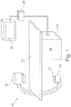
Fig. 1 schematically shows an X-raymedical imaging system 10 which may be used during an intervention procedure to provide an image representation thereby supporting a surgeon in positioning an intervention device within a patient in accordance with an embodiment of the present invention. - The
imaging system 10 comprises an X-ray image acquisition device with anX-ray source 12 provided to generate X-ray radiation. TheX-ray source 12 comprises acollimator 13 including shutters and wedges (not shown) in order to collimate the X-radiation onto a region of interest. A table 14 is provided to receive a patient to be examined. Furthermore, an X-rayimage detection module 16 is located opposite to theX-ray source 12. During an imaging procedure, the patient is located on the table 14, i.e. between theX-ray source 12 and thedetection module 16. X-rays are emitted by theX-ray source 12 and transmitted through the patient before being detected by thedetection module 16. - The
detection module 16 is sending data to adata processing unit 18 which is connected to both theX-ray source 12 and thedetection module 16. Thedata processing unit 18 is adapted to acquire anatomy images and processing same in accordance with the processing steps outlined above and hereinafter. Thus, thedata processing unit 18 comprises data interfaces to acquire pre-live and live anatomy images and is adapted to detect the location of an intervention device in a live anatomy image in order to thereupon control thecollimator 13 of theX-ray source 12 to focus onto such location. Furthermore, thedata processing unit 18 is adapted for merging of pre-live and live anatomy images. Accordingly, thedata processing unit 18 may serve as amedical imaging device 19 according to an embodiment of the present invention. - Furthermore, the
data processing unit 18 is connected to adisplay device 20 for displaying information to a person operating the X-ray imaging system, i.e. a clinician such as a cardiologist or a cardiac surgeon. For example, image representations indicating a current location of an intervention device within the patient may be displayed on thedisplay device 20. The display device may also be used to display two images such as e.g. both the image representation indicating a current location of an intervention device as provided by themedical imaging device 19 as well as a live image which has not been further processed and which provides a good live information on the operation site. Furthermore, aninterface unit 22 is provided in order to enable an information input by the operating person. - It is noted that the example shown in
Fig. 1 is of a so-called C-type X-ray image acquisition device. Of course, the invention may also relate to other types of medical imaging systems. - In the following, an operation mode and process steps to be performed by the medical imaging system in accordance with an embodiment of the present invention shall be described with reference to the chart shown in
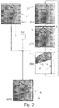
Fig. 2 . - In order to perform a medical imaging method in accordance with embodiments of the present invention, two data inputs are performed as follows.
- First, a
pre-live anatomy image 1 or a sequence of pre-live anatomy images is acquired (step (S1)). Therein, a pre-live anatomy image represents a region of interest within a patient. For example, a cardiac vessel region is represented. The pre-live anatomy image is typically acquired prior to or in the periphery of an intervention procedure, i.e. at pre-interventional or peri-interventional phases, in which an intervention device such as e.g. a guide-wire is to be positioned within the region of interest. Typically, the pre-live anatomy image can be an angiography image. Preferably, a sequence of angiographic images forming a pre-live anatomy image sequence is acquired. In general this sequence does not contain any intervention devices that will be manoeuvred during the actual intervention procedure such as e.g. a wire tip, but it may contain devices that will not be manoeuvred during the intervention procedure such as e.g. a catheter injection tip. - Generally, the pre-live anatomy image or pre-live anatomy image sequence features the same region of interest as subsequently featured during the intervention procedure with the live anatomy images. However, in the pre-live anatomy image(s) features may possibly be enhanced by an increased contrast as such images may be acquired with a higher X-ray dose than used in subsequent live anatomy image acquisition. Furthermore, during acquisition of the pre-live anatomy image(s) a contrast medium may be present within the region of interest. For example, in a preceding step, a contrast medium may be injected into the patient's vessels. Thereby, exposure conditions may be enhanced thereby enabling better image contrast compared to subsequently acquired live anatomy image acquisition.
- The pre-live anatomy image(s) may be acquired with the
same imaging system 10 as used subsequently for acquiring the live anatomy images during the intervention procedure. Alternatively a DRR (digitally reconstructed radiograph) sequence or a projection sequence from a 3D volume acquired on the same or another X-ray medical imaging system or even from another modality such as CT (computer tomography) or MR (magnetic resonance) may be used for acquiring the pre-live anatomy image(s). In case of MR the reconstruction of an "X-ray-like pre-live image sequence" may require some extra computations. Alternatively, an "MR-like" background may also be sufficient for guidance during an X-ray intervention. In case of a DRR, it may not be necessary to calculate a full DRR as background image, but only a vessel or organ that is relevant as a road map to guide the intervention device. The pre-live anatomy image may be 2D, 3D, 4D or even more dimensional. Typically in Electro-Physiology (EP) procedures such as Atrial Fibrilation (AF) procedures, one often resorts to a pre-live segmentation of part of the heart in a CT volume, typically the left atrium, which might be used as a source for pre-live anatomy image generation. The pre-live anatomy image can therefore be constituted from segmentation or modelling data, as opposed to direct acquisition data. In AF, typically the segmented left atrium from a CT volume, can be projected and variously rendered onto a 2D plane compatible with the live image plane. The term image in the expression "pre-live anatomy image" should therefore be understood in a broad way, as a data source representing the anatomy and compatible with a subsequent merging with the live images. - Another typical intervention is Percutaneous aortic Valve Replacement (PVR). In this kind of procedures, the aortic cross and aortic root are typically segmented from a CT volume. This segmentation can also serve to produce a pre-live anatomy image.
- As a second data input, a first live anatomy image 2 of the region of interest is acquired (step (S2)). For this image acquisition, an image acquisition device comprising an adjustable collimator device is used. Typically, an X-ray fluoroscopy imaging device is used, such fluoroscopy imaging device comprising a collimator device which includes at least one of an X-ray absorbing shutter device and an X-ray attenuating wedge device. However, the collimator device may also include other types of controllable X-ray absorbing or X-ray attenuating devices which may be controlled such that their X-ray absorbing or X-ray attenuating properties may be locally varied. Herein, X-ray absorbing may mean that no X-rays are transmitted through the X-ray absorbing devices; X-ray attenuating may mean that X-rays are partially transmitted through the X-ray absorbing devices. Using the example of a collimator having a shutter and/or wedge device, by introducing the shutter and/or wedge into an X-ray beam emitted by the X-ray source, such X-ray beam may be collimated, i.e. its lateral dimensions may be restricted such that the imaging area from which the live anatomy image is acquired may be limited. While for acquiring the first live anatomy image, the collimator device may be in its fully opened state such that the entire area of the region of interest is imaged, subsequent live anatomy images may be acquired with a restricted setting of the collimator device such that only a partial area of the region of interest adjacent to a previously identified location of an intervention device is imaged. The live anatomy image(s) is typically acquired with the intervention device being present within the region of interest. For example, in cardiac catheterization, this intervention device can be a
catheter injection tip 3 and awire tip 4. In AF procedures, the intervention device may be in fact multiple, and constituted by a certain number of electrodes and catheters. In PVR interventions, the device is typically constituted by the artificial valve to be deployed. However, the device can also include a monitoring ultrasound probe. Generally speaking, the term device can therefore refer to several separated entities which are manoeuvred during the intervention, and within the region of interest. These entities might be prosthesis, delivery tools, measuring tools, etc. - Subsequent to acquiring a first live anatomy image, a location of the intervention device(s) of interest such as of the
wire tip 3 and/or theinjection tip 4 is identified within the live anatomy image (step (S3)). In other words, the intervention device(s) may be tracked within a sequence of live anatomy images. The location of the intervention device(s) may be determined based on analyzing location information, shape information and/or radiometric content comprised in the first live anatomy image. For identifying the current location of the intervention device(s), conventional segmentation tools may be used. Such segmentation tools preferably allow real-time identification of the intervention device(s). However, the determination of the device(s) location might also be determined by non-imaging material, such as through active localiser, typically Electro-Magnetic trackers (EM trackers). When used, those trackers are directly mounted on the device(s) of interest. - The term location should be understood in a broad sense. It might refer to the location of a precise point of the device, but it also might refer to several points on the device, or even to all the pixels of the live image corresponding to the device. When several devices are involved, each individual device might be located, or conversely, a global representative location of all these devices might be sufficient, typically a barycentre location.
- Furthermore, in identifying the location of the intervention device(s), a prediction on a future location of the intervention device(s) based on current location parameters or motion parameters may be involved. For this purpose, a trajectory of the intervention device(s) may be analyzed and a probability map of their predicted future locations may be built. This may allow anticipating the devices movements such that it may be possible to predict the
future location 5 of the intervention device(s). Usual temporal filtering methods may be used to generate such predictions. - After having identified the current location of an intervention device and, optionally, a predicted location of the intervention device, settings of the collimator device comprised in the live image acquisition device are adjusted based on such identified location (step S4). When the collimator device comprises at least one of a shutter 7 and a
wedge 6 device for locally reducing an X-radiation flow from the X-ray source through the patient towards the X-ray detector, such settings of the collimator device may indicate a positioning of the shutter 7 orwedge 6 device. In other words, by adjusting the settings of the collimator device, continuous shuttering or wedging, i.e. repositioning of the shutter 7 orwedge 6, may be applied so as to keep the intervention device visible within a live anatomy image to be subsequently acquired while occluding out the field of view as much as possible. - Once, the predicted
locations 5 of theintervention devices locations 5 and the setting of the collimator device may be adjusted such thatwedges 6 and shutters 7 of the collimator device are repositioned in order to keep the non-occluded areas 8 as small as possible. At the same time, thewedges 6 and shutters 7 may be positioned such that a risk that theintervention devices intervention devices - In case it is detected that in a subsequent image acquisition the intervention device moved out of the collimated, non-occluded area 8, the collimator may be completely opened such that the intervention device may be found within the entire live image and the shutter or wedge may then be repositioned.
- After having adjusted the settings of the collimator device, the entire process including steps (S2) to (S4) may be repeated such that a subsequent live anatomy image of a non-occluded area 8 may be acquired with the collimator device of the live image acquisition device being in the adjusted settings. In other words, predicted locations of the
intervention devices - Information comprised in the live anatomy image may then be merged into the pre-live anatomy image in order to provide an image representation 9 in which both the information about the current position of the
intervention devices - Merging of the two anatomy images may require complex computations which however are generally known as so-called inverse-road mapping techniques as for example described in PCT application number
PCT/IB2010/054208 - Once the spatio-temporal transform is known, it may be applied to a region adjacent to the tracked intervention devices that are not present in the pre-live anatomy image(s), i.e. typically those intervention devices which are maneuverer in the live anatomy images, e.g. the
wire tip 4. Thereby, a portion of the second live anatomy image in a region adjacent to the location of the identifiedintervention device 4 is represented in the final image representation. In other words, in the final image representation provided by merging the live anatomy image and the pre-live anatomy image, a region adjacent to the location of the identifiedintervention device 4 is represented mainly based on the live anatomy image. A region further distant to the location of the identifiedintervention device 4 is represented mainly based on the pre-live anatomy image. Typically, a transparency level may be determined below which only the background anatomy from the pre-live anatomy image is shown and above which the intervention device shown in the live anatomy image and the anatomy background shown in the pre-live anatomy image are nicely blended together. - Alternatively, information about the identified location of the intervention device may be used in order to visualize a model of the intervention device or any location identifier at the corresponding position within the finally provided image representation.
- While the process steps to be performed by the medical imaging device according to an embodiment of the present invention are described above with respect to a first and subsequent live anatomy image only, a plurality of live anatomy images may be acquired during the intervention procedure by continuously repeating the process steps of identifying the location of the intervention device, adjusting the settings of the collimator device and acquiring a subsequent live anatomy image using the adjusted collimator settings. By merging each of the live anatomy images with the pre-live anatomy image or a selected image out of a sequence of pre-live anatomy images, a sequence of image representations may be provided. In such sequence, the motion of the intervention device may be clearly represented as the intervention device is continuously tracked and the live anatomy images focused on the tracked intervention device are then superimposed to a respective pre-live anatomy image possibly having a higher image contrast than the live anatomy images due to the possible use of a higher X-ray dose and/or a contrast medium.
- As an option, the proposed medical imaging device may also include a device-based automatic exposure control (AEC), indicated in
Fig. 2 as (S6). The AEC may be adapted to the proposed imaging method in accordance with embodiments of the present invention. This means that both a total image rendering as well as an intervention device detection and tracking process may be optimized through an appropriate control of radiation exposures. Several possibilities can be considered. For example, obvious real-time exclusion of collimated areas, i.e. areas shaded by wedging or shuttering, from a measuring field taken into account by the AEC may be performed. Additionally or alternatively, a fine adaptation of the AEC may be performed so that the total rendered scene, i.e. the background anatomy provided by the pre-live anatomy image together with image information on the intervention device provided by the live anatomy image, may be optimized from a visual perception point of view. Furthermore, the AEC may be adapted in real-time so as to reach a compromise between an optimal rendering of the resulting composite scene, i.e. background anatomy information plus intervention device information, and a detectability of the intervention devices. All such possible controls may be of course dynamic, i.e. continuously updated with real-time information coming from both the pre-live andlive anatomy images 1, 2 and the intervention device tracking/prediction module. - Finally, important aspects and features of embodiments of the present invention shall be summarized in an alternative wording. Aspects of the invention rely on two main features:
- a) On the one hand, it is proposed to track intervention devices of interest during a targeted intervention and to adapt a radiation limitation on an image basis to locations or predicted locations of those intervention devices. Such adaption may be as tight as possible, optimizing both radiation reduction and a probability of keeping the intervention devices within a continuously adapted non-occluded field of view;
- b) On the other hand, to suppress a troublesome visual impression undoubtedly created by continuously moving shutters or wedges of a collimator device, it is proposed to resort to a generalization of an inverse road mapping technique. Thereby, only surroundings of the intervention devices are taken from live anatomy images and are shown over pre-live non-tightly-shuttered background anatomy images, typically but not necessarily contrast-filled angiogram images.
- In other words, device tracking is used to determine and predict locations of intervention devices of interest; image-level control is involved to apply dynamic tight collimation, concentrating radiation on an intervention focal point only that is around the tracked intervention devices; only live image data in a close vicinity of those tracked intervention devices are retained; they are projected and superimposed to a pre-live background anatomy image sequence which might constitute a richer background setting because it may be acquired with more doses and potentially with contrast medium.
- With the proposed technique, a live radiation toll may be optimized to the visibility of the intervention devices only, while restoring an occluded background with pre-live anatomy image content, possibly richer in contrast information and possibly being acquired in diagnostic conditions.
- The proposed invention may be used in a variety of X-ray intervention applications. In particular, it may be used in complex cardiac percutaneous catheterization procedures where a surgeon has to deal with both strong respiratory and cardiac motions. However, it may also be applied in many less demanding applications such as vascular or possibly neuro interventions.
- Finally, it has to be noted that herein the word "comprising" does not exclude other elements or steps and that the indefinite article "a" or "an" does not exclude a plurality. Reference signs in the claims should not be construed as limiting the scope.
-
- 1
- Pre-live anatomy image
- 2
- Live anatomy image
- 3
- Intervention device/injection tip
- 4
- Intervention device/wire tip
- 5
- Predicted location
- 6
- Wedge
- 7
- Shutter
- 8
- Non-occluded area
- 9
- image representation
Claims (12)
- An X-ray medical imaging device (19) for providing an image representation (9) supporting positioning of an intervention device (3, 4) in a region of interest during an intervention procedure, the medical imaging device being adapted for performing the following steps:(i) acquiring (S1) a sequence of pre-live anatomy images (1) including the region of interest;(ii) acquiring (S2) a live anatomy image (2) including the region of interest using a live image acquisition device (10) comprising an adjustable collimator device (13) with the collimator device being in previously set settings;(iii) identifying (S3) a location (5) of the intervention device within the live anatomy image;(iv) adjusting (S4) settings of the collimator device based on the identified location of the intervention device for subsequently acquiring a further live anatomy image including the region of interest using the live image acquisition device with the collimator device being in the adjusted settings;(v) providing (S5) the image representation by merging information from the live anatomy image into one of the pre-live anatomy images, wherein a spatio-temporal transformation linking a selected one of the pre-live anatomy images and the live anatomy image is performed before the merging,wherein the live anatomy image and the selected one of the pre-live anatomy images are merged such that in the provided image representation a region adjacent to the location of the identified intervention device is represented mainly based on the live anatomy image and a region distant to the location of the identified intervention device is represented mainly based on the selected one of the pre-live anatomy images.
- Device of claim 1, wherein steps (ii) to (v) are continuously repeated for providing a sequential image representation.
- Device of claim 2, wherein in a repeated acquiring of the live anatomy image, the settings of the collimator are adjusted such that the acquiring of the live anatomy image is restricted to a partial non-occluded area (8) of the region of interest adjacent to the location of the identified intervention device.
- Device of one of claims 1 to 3, wherein the live image acquisition device comprises an X-ray imaging device, wherein the collimator device comprises at least one of an X-ray absorbing device (7) and an X-ray attenuating device (6) for locally reducing X-radiation flow and wherein the settings of the collimator device relate to a positioning of the at least one of the X-ray absorbing device (7) and an X-ray attenuating device (6).
- Device of one of claims 1 to 4, wherein, in step (iii), the identifying a location of the intervention device involves a prediction on a future location (5) of the intervention device based on current location parameters and motion parameters.
- Device of one of claims 1 to 5, wherein the pre-live image is acquired with a higher image contrast than the live image.
- Device of one of claims 1 to 6, wherein the pre-live image is an angiography image.
- Device of one of claims 1 to 7, wherein the live image is a fluoroscopy image.
- Device of one of claims 1 to 8, wherein in step (iii) a location of the intervention device is determined based on analyzing location information, shape information and radiometric content comprised in the live anatomy image.
- An X-ray medical imaging system comprising:a pre-live image acquisition device (10) for acquiring high-contrast images;a live image acquisition device (10) for acquiring low-contrast images, the live image acquisition device comprising an adjustable collimator device (13);a medical imaging device (19) according to any of claims 1 to 9; anda display device (20) for displaying the image representation (9) provided by the medical imaging device.
- Computer program adapted for, when executed on a computing device, performing an X-ray medical imaging method for providing an image representation supporting positioning of an intervention device in a region of interest during an intervention procedure, the medical imaging method including the following steps:(i) acquiring (S1) a sequence of pre-live anatomy images representing the region of interest;(ii) acquiring (S2) a live anatomy image representing the region of interest using a live image acquisition device comprising an adjustable collimator device;(iii) identifying (S3) a location of the intervention device within the live image with the collimator device being in previously set settings;(iv) adjusting (S4) settings of the collimator device based on the identified location of the intervention device for subsequently acquiring a further live anatomy image representing the region of interest using the live image acquisition device with the collimator device being in the adjusted settings;(v) providing (S5) the image representation by merging information from the live anatomy image into one of the pre-live anatomy images wherein a spatio-temporal transformation of a selected one of the pre-live image and the live image is performed before the merging,wherein the live anatomy image and the selected one of the pre-live anatomy images are merged such that in the provided image representation a region adjacent to the location of the identified intervention device is represented mainly based on the live anatomy image and a region distant to the location of the identified intervention device is represented mainly based on the selected one of the pre-live anatomy images.
- Computer readable medium comprising stored thereon the computer program of claim 11.
Priority Applications (1)
| Application Number | Priority Date | Filing Date | Title |
|---|---|---|---|
| EP12710348.9A EP2685900B1 (en) | 2011-03-15 | 2012-03-05 | Medical imaging device for providing an image representation supporting in positioning an intervention device |
Applications Claiming Priority (3)
| Application Number | Priority Date | Filing Date | Title |
|---|---|---|---|
| EP11305285 | 2011-03-15 | ||
| EP12710348.9A EP2685900B1 (en) | 2011-03-15 | 2012-03-05 | Medical imaging device for providing an image representation supporting in positioning an intervention device |
| PCT/IB2012/051021 WO2012123850A1 (en) | 2011-03-15 | 2012-03-05 | Medical imaging device for providing an image representation supporting in positioning an intervention device |
Publications (2)
| Publication Number | Publication Date |
|---|---|
| EP2685900A1 EP2685900A1 (en) | 2014-01-22 |
| EP2685900B1 true EP2685900B1 (en) | 2022-12-21 |
Family
ID=45876823
Family Applications (1)
| Application Number | Title | Priority Date | Filing Date |
|---|---|---|---|
| EP12710348.9A Active EP2685900B1 (en) | 2011-03-15 | 2012-03-05 | Medical imaging device for providing an image representation supporting in positioning an intervention device |
Country Status (5)
| Country | Link |
|---|---|
| US (1) | US9700209B2 (en) |
| EP (1) | EP2685900B1 (en) |
| JP (1) | JP6108474B2 (en) |
| CN (1) | CN103429158B (en) |
| WO (1) | WO2012123850A1 (en) |
Families Citing this family (38)
| Publication number | Priority date | Publication date | Assignee | Title |
|---|---|---|---|---|
| WO2012123850A1 (en) * | 2011-03-15 | 2012-09-20 | Koninklijke Philips Electronics N.V. | Medical imaging device for providing an image representation supporting in positioning an intervention device |
| JP5954762B2 (en) * | 2011-11-29 | 2016-07-20 | 東芝メディカルシステムズ株式会社 | X-ray diagnostic imaging equipment |
| RU2015111008A (en) | 2012-08-27 | 2016-10-20 | Конинклейке Филипс Н.В. | AUTOMATIC COLLIMATION WITH A DOCTOR AWARENESS |
| BR112015007350A2 (en) * | 2012-10-05 | 2017-07-04 | Koninklijke Philips Nv | apparatus for controlling x-ray beam collimation, method for controlling x-ray beam collimation, x-ray beam collimator, x-ray imaging system, computer program element for controlling an apparatus and readable medium computer |
| WO2014091380A1 (en) * | 2012-12-13 | 2014-06-19 | Koninklijke Philips N.V. | Interventional system |
| WO2014097086A1 (en) * | 2012-12-21 | 2014-06-26 | Koninklijke Philips N.V. | Interventional x-ray system with automatic centration of roi in centre of image |
| US9050056B2 (en) * | 2012-12-26 | 2015-06-09 | Biosense Webster (Israel) Ltd. | Reduced X-ray exposure by simulating images |
| JP6104611B2 (en) * | 2013-01-16 | 2017-03-29 | 東芝メディカルシステムズ株式会社 | X-ray diagnostic equipment |
| EP2760028B1 (en) * | 2013-01-23 | 2018-12-12 | Samsung Electronics Co., Ltd | Radiation generator |
| WO2014155280A1 (en) | 2013-03-25 | 2014-10-02 | Koninklijke Philips N.V. | Interventionist hand radiation protection |
| CN105246411B (en) | 2013-04-03 | 2019-10-18 | 皇家飞利浦有限公司 | Intervene x-ray system |
| CN104436450B (en) * | 2013-09-25 | 2018-07-31 | 苏州雷泰医疗科技有限公司 | Radiotherapy unit light limiting means and radiotherapy unit |
| KR102201407B1 (en) | 2013-11-18 | 2021-01-12 | 삼성전자주식회사 | X-ray imaging apparatus and control method thereof |
| KR102233319B1 (en) * | 2014-01-20 | 2021-03-29 | 삼성전자주식회사 | A method for tracing a region of interest, a radiation imaging apparatus, a method for controlling the radiation imaging apparatus and a radiographic method |
| JP6357805B2 (en) * | 2014-03-05 | 2018-07-18 | 株式会社島津製作所 | X-ray equipment |
| WO2015162101A1 (en) * | 2014-04-24 | 2015-10-29 | Koninklijke Philips N.V. | Recognizer of staff or patient body parts using markers to prevent or reduce unwanted irradiation |
| JP6566714B2 (en) * | 2014-05-19 | 2019-08-28 | キヤノンメディカルシステムズ株式会社 | X-ray computed tomography apparatus, image display apparatus and image display method |
| JP6794361B2 (en) * | 2015-01-22 | 2020-12-02 | コーニンクレッカ フィリップス エヌ ヴェKoninklijke Philips N.V. | Visualization of end grafts by optical shape detection |
| WO2016146380A1 (en) * | 2015-03-16 | 2016-09-22 | Koninklijke Philips N.V. | Automatic movement detection |
| DE102015205955A1 (en) * | 2015-04-01 | 2016-10-06 | Siemens Healthcare Gmbh | Method and device for the automated navigation support of a medical instrument that can be inserted into an examination object |
| WO2016200370A1 (en) * | 2015-06-09 | 2016-12-15 | Siemens Healthcare Gmbh | Real-time collimation and roi-filter positioning in x-ray imaging via automatic detection of the landmarks of interest |
| JP7103790B2 (en) * | 2015-06-25 | 2022-07-20 | コーニンクレッカ フィリップス エヌ ヴェ | Medical interventional imaging device |
| WO2017055380A2 (en) * | 2015-09-30 | 2017-04-06 | Koninklijke Philips N.V. | A method for device localization using magnetic resonance imaging |
| US10342505B2 (en) * | 2016-03-31 | 2019-07-09 | General Electric Company | System and method for adjusting a radiation dose during imaging of an object within a subject |
| EP3457935B1 (en) * | 2016-05-16 | 2023-07-05 | TRACKX Technology, LLC | System for image localization of effecters during a medical procedure |
| JP7049325B6 (en) * | 2016-09-23 | 2022-06-01 | コーニンクレッカ フィリップス エヌ ヴェ | Visualization of image objects related to instruments in in-vitro images |
| JP2018114203A (en) * | 2017-01-20 | 2018-07-26 | 株式会社島津製作所 | X-ray fluoroscopic imaging apparatus |
| CN108937975A (en) * | 2017-05-19 | 2018-12-07 | 上海西门子医疗器械有限公司 | X-ray exposure area adjusting method, storage medium and X-ray system |
| EP3658032A4 (en) * | 2017-07-26 | 2021-03-03 | Shenzhen Xpectvision Technology Co., Ltd. | X-ray imaging system and method of x-ray image tracking |
| EP3456266A1 (en) * | 2017-09-14 | 2019-03-20 | Koninklijke Philips N.V. | Ultrasound image processing |
| EP3459463A1 (en) | 2017-09-26 | 2019-03-27 | Koninklijke Philips N.V. | Device and method for determining a volume of projection of a dual-axis computed tomography system |
| US10849711B2 (en) * | 2018-07-11 | 2020-12-01 | DePuy Synthes Products, Inc. | Surgical instrument mounted display system |
| CN109620275B (en) * | 2019-01-17 | 2023-02-28 | 深圳市安健科技股份有限公司 | Imaging method and terminal for medical image |
| CN109820528A (en) * | 2019-03-08 | 2019-05-31 | 江苏霆升科技有限公司 | A kind of X-ray machine focus method, device and equipment based on picture recognition |
| JP2022526527A (en) * | 2019-03-26 | 2022-05-25 | コーニンクレッカ フィリップス エヌ ヴェ | Persistent guidewire identification |
| JP2020185145A (en) * | 2019-05-14 | 2020-11-19 | 株式会社島津製作所 | X-ray imaging apparatus |
| US11241295B2 (en) * | 2020-04-24 | 2022-02-08 | Terry L Ancar | System and method for automatic adjustment of fluoroscopic imaging using a motorized collimator |
| KR102305965B1 (en) | 2021-05-25 | 2021-09-29 | 재단법인 아산사회복지재단 | Device and method for detecting guidewire |
Family Cites Families (33)
| Publication number | Priority date | Publication date | Assignee | Title |
|---|---|---|---|---|
| US5253169A (en) * | 1991-11-29 | 1993-10-12 | General Electric Company | Method and apparatus for reducing x-ray dosage during fluoroscopic examinations |
| US5282254A (en) * | 1992-06-29 | 1994-01-25 | Siemens Corporate Research, Inc. | Method for locating an edge portion of an aperture in a filter member in X-ray fluoroscopy apparatus |
| US6470207B1 (en) | 1999-03-23 | 2002-10-22 | Surgical Navigation Technologies, Inc. | Navigational guidance via computer-assisted fluoroscopic imaging |
| DE10020258A1 (en) * | 2000-04-25 | 2001-11-08 | Siemens Ag | Method for operating a CT device |
| US6359956B1 (en) * | 2000-12-15 | 2002-03-19 | Ge Medical Systems Global Technology Company, Llc | Reconstruction in helical computed tomography using asymmetric modeling of detector sensitivity |
| US6836570B2 (en) * | 2001-11-14 | 2004-12-28 | Eastman Kodak Company | Method for contrast-enhancement of digital portal images |
| JP4070493B2 (en) * | 2002-04-03 | 2008-04-02 | 株式会社東芝 | X-ray diagnostic apparatus and medical image analysis apparatus |
| DE10240727A1 (en) | 2002-09-04 | 2004-03-18 | Philips Intellectual Property & Standards Gmbh | Imaging system and method for optimizing an x-ray image |
| EP1651112B1 (en) * | 2003-07-30 | 2010-10-27 | Philips Intellectual Property & Standards GmbH | X-ray unit having an automatically adjustable collimator |
| US20050053267A1 (en) * | 2003-09-05 | 2005-03-10 | Varian Medical Systems Technologies, Inc. | Systems and methods for tracking moving targets and monitoring object positions |
| US7453983B2 (en) * | 2005-01-20 | 2008-11-18 | Carestream Health, Inc. | Radiation therapy method with target detection |
| EP1864112B1 (en) * | 2005-03-25 | 2015-05-06 | Massachusetts Institute of Technology | Device and method for hilbert phase imaging |
| WO2006123581A1 (en) * | 2005-05-18 | 2006-11-23 | Hitachi Medical Corporation | Radiograph and image processing program |
| DE102006006038B4 (en) * | 2006-02-09 | 2011-02-17 | Siemens Ag | System for illustrated tracking of an at least partially introduced into a study object, moving medical instrument |
| WO2007138979A1 (en) * | 2006-05-25 | 2007-12-06 | Hitachi Medical Corporation | X-ray ct apparatus |
| US7869637B2 (en) * | 2006-07-31 | 2011-01-11 | Siemens Medical Solutions Usa, Inc. | Histogram calculation for auto-windowing of collimated X-ray image |
| FR2904750B1 (en) * | 2006-08-03 | 2008-10-17 | Gen Electric | METHOD FOR THREE-DIMENSIONAL RECONSTRUCTION OF AN OUTER ENVELOPE OF A BODY OF AN X-RAY APPARATUS |
| US7853063B2 (en) * | 2006-08-04 | 2010-12-14 | Carestream Health, Inc. | Method for producing a cropped medical image |
| US7831096B2 (en) | 2006-11-17 | 2010-11-09 | General Electric Company | Medical navigation system with tool and/or implant integration into fluoroscopic image projections and method of use |
| US8005284B2 (en) * | 2006-12-07 | 2011-08-23 | Kabushiki Kaisha Toshiba | Three dimensional image processing apparatus and x-ray diagnosis apparatus |
| JP5084291B2 (en) * | 2007-02-06 | 2012-11-28 | キヤノン株式会社 | Image processing apparatus and method |
| WO2009008070A1 (en) * | 2007-07-11 | 2009-01-15 | Shimadzu Corporation | Radiation image picking-up device |
| US20100174120A1 (en) | 2007-09-05 | 2010-07-08 | E.I. Du Pont De Nemours And Company | Processes for making dibutyl ethers from isobutanol |
| WO2009124130A1 (en) * | 2008-04-01 | 2009-10-08 | Infimed, Inc. | Multi-pass edge detection of collimator blades in digital radiography images |
| JP2010075245A (en) * | 2008-09-24 | 2010-04-08 | Fujifilm Corp | Radiographic imaging apparatus |
| CN102202576B (en) | 2008-10-10 | 2015-04-08 | 皇家飞利浦电子股份有限公司 | Angiographic image acquisition system and method with automatic shutter adaptation for yielding a reduced field of view covering a segmented target structure or lesion for decreasing x-radiation dose in minimally invasive x-ray-guided interventions |
| DE102009015830B4 (en) * | 2009-04-01 | 2017-11-23 | Siemens Healthcare Gmbh | A method of controlling an X-ray device while capturing a sequence of two-dimensional images for tracking a medical instrument used in a minimally invasive procedure |
| US9095308B2 (en) | 2009-09-29 | 2015-08-04 | Koninklijke Philips N.V. | Vascular roadmapping |
| US8467584B2 (en) * | 2009-10-22 | 2013-06-18 | Siemens Medical Solutions Usa, Inc. | Use of multifocal collimators in both organ-specific and non-specific SPECT acquisitions |
| JP5537262B2 (en) * | 2010-05-28 | 2014-07-02 | 株式会社東芝 | X-ray diagnostic imaging equipment |
| US8238518B2 (en) * | 2010-06-23 | 2012-08-07 | The Institute Of Cancer Research | Radiotherapy system |
| US9295435B2 (en) * | 2011-02-07 | 2016-03-29 | Koninklijke Philips N.V. | Image representation supporting the accurate positioning of an intervention device in vessel intervention procedures |
| WO2012123850A1 (en) * | 2011-03-15 | 2012-09-20 | Koninklijke Philips Electronics N.V. | Medical imaging device for providing an image representation supporting in positioning an intervention device |
-
2012
- 2012-03-05 WO PCT/IB2012/051021 patent/WO2012123850A1/en active Application Filing
- 2012-03-05 EP EP12710348.9A patent/EP2685900B1/en active Active
- 2012-03-05 CN CN201280013012.7A patent/CN103429158B/en active Active
- 2012-03-05 JP JP2013558537A patent/JP6108474B2/en active Active
- 2012-03-05 US US14/003,486 patent/US9700209B2/en active Active
Also Published As
| Publication number | Publication date |
|---|---|
| JP6108474B2 (en) | 2017-04-05 |
| US9700209B2 (en) | 2017-07-11 |
| EP2685900A1 (en) | 2014-01-22 |
| CN103429158B (en) | 2017-12-26 |
| CN103429158A (en) | 2013-12-04 |
| US20130343631A1 (en) | 2013-12-26 |
| WO2012123850A1 (en) | 2012-09-20 |
| JP2014508020A (en) | 2014-04-03 |
Similar Documents
| Publication | Publication Date | Title |
|---|---|---|
| EP2685900B1 (en) | Medical imaging device for providing an image representation supporting in positioning an intervention device | |
| US7761136B2 (en) | Medical image processing apparatus for scanning based on a set three-dimensional region of interest | |
| US9280837B2 (en) | Angiographic image acquisition system and method with automatic shutter adaptation for yielding a reduced field of view covering a segmented target structure or lesion for decreasing X-radiation dose in minimally invasive X-ray-guided interventions | |
| EP1865850B1 (en) | Method and apparatus for the observation of a catheter in a vessel system | |
| EP2800516B1 (en) | Real-time display of vasculature views for optimal device navigation | |
| US9042628B2 (en) | 3D-originated cardiac roadmapping | |
| EP3227857B1 (en) | Device-based motion-compensated digital subtraction angiography | |
| EP2863799B1 (en) | Temporal anatomical target tagging in angiograms | |
| JP2009022754A (en) | Method for correcting registration of radiography images | |
| CN108430376B (en) | Providing a projection data set | |
| EP2931127B1 (en) | Interventional system | |
| US11723616B2 (en) | Method of verifying a position of an interventional device | |
| US20240099674A1 (en) | Computer-implemented method for operating an x-ray facility, x-ray facility, computer program, and electronically readable data carrier | |
| EP4062835A1 (en) | Subtraction imaging | |
| JP2022147619A (en) | Image display device and image display program |
Legal Events
| Date | Code | Title | Description |
|---|---|---|---|
| PUAI | Public reference made under article 153(3) epc to a published international application that has entered the european phase |
Free format text: ORIGINAL CODE: 0009012 |
|
| 17P | Request for examination filed |
Effective date: 20131015 |
|
| AK | Designated contracting states |
Kind code of ref document: A1 Designated state(s): AL AT BE BG CH CY CZ DE DK EE ES FI FR GB GR HR HU IE IS IT LI LT LU LV MC MK MT NL NO PL PT RO RS SE SI SK SM TR |
|
| DAX | Request for extension of the european patent (deleted) | ||
| STAA | Information on the status of an ep patent application or granted ep patent |
Free format text: STATUS: EXAMINATION IS IN PROGRESS |
|
| 17Q | First examination report despatched |
Effective date: 20170404 |
|
| RAP1 | Party data changed (applicant data changed or rights of an application transferred) |
Owner name: KONINKLIJKE PHILIPS N.V. |
|
| STAA | Information on the status of an ep patent application or granted ep patent |
Free format text: STATUS: EXAMINATION IS IN PROGRESS |
|
| STAA | Information on the status of an ep patent application or granted ep patent |
Free format text: STATUS: EXAMINATION IS IN PROGRESS |
|
| REG | Reference to a national code |
Ref country code: DE Ref legal event code: R079 Ref document number: 602012079132 Country of ref document: DE Free format text: PREVIOUS MAIN CLASS: A61B0006060000 Ipc: A61B0006120000 |
|
| GRAP | Despatch of communication of intention to grant a patent |
Free format text: ORIGINAL CODE: EPIDOSNIGR1 |
|
| STAA | Information on the status of an ep patent application or granted ep patent |
Free format text: STATUS: GRANT OF PATENT IS INTENDED |
|
| RIC1 | Information provided on ipc code assigned before grant |
Ipc: A61B 90/00 20160101ALI20220622BHEP Ipc: A61B 6/00 20060101ALI20220622BHEP Ipc: A61B 6/06 20060101ALI20220622BHEP Ipc: A61B 6/12 20060101AFI20220622BHEP |
|
| INTG | Intention to grant announced |
Effective date: 20220720 |
|
| RIN1 | Information on inventor provided before grant (corrected) |
Inventor name: STEGEHUIS, HERMAN Inventor name: HOORNAERT, BART PIERRE ANTOINE JOZEF Inventor name: FLORENT, RAOUL |
|
| GRAS | Grant fee paid |
Free format text: ORIGINAL CODE: EPIDOSNIGR3 |
|
| GRAA | (expected) grant |
Free format text: ORIGINAL CODE: 0009210 |
|
| STAA | Information on the status of an ep patent application or granted ep patent |
Free format text: STATUS: THE PATENT HAS BEEN GRANTED |
|
| AK | Designated contracting states |
Kind code of ref document: B1 Designated state(s): AL AT BE BG CH CY CZ DE DK EE ES FI FR GB GR HR HU IE IS IT LI LT LU LV MC MK MT NL NO PL PT RO RS SE SI SK SM TR |
|
| REG | Reference to a national code |
Ref country code: GB Ref legal event code: FG4D |
|
| REG | Reference to a national code |
Ref country code: CH Ref legal event code: EP |
|
| REG | Reference to a national code |
Ref country code: DE Ref legal event code: R096 Ref document number: 602012079132 Country of ref document: DE |
|
| REG | Reference to a national code |
Ref country code: AT Ref legal event code: REF Ref document number: 1538551 Country of ref document: AT Kind code of ref document: T Effective date: 20230115 |
|
| REG | Reference to a national code |
Ref country code: IE Ref legal event code: FG4D |
|
| REG | Reference to a national code |
Ref country code: LT Ref legal event code: MG9D |
|
| REG | Reference to a national code |
Ref country code: NL Ref legal event code: MP Effective date: 20221221 |
|
| PG25 | Lapsed in a contracting state [announced via postgrant information from national office to epo] |
Ref country code: SE Free format text: LAPSE BECAUSE OF FAILURE TO SUBMIT A TRANSLATION OF THE DESCRIPTION OR TO PAY THE FEE WITHIN THE PRESCRIBED TIME-LIMIT Effective date: 20221221 Ref country code: NO Free format text: LAPSE BECAUSE OF FAILURE TO SUBMIT A TRANSLATION OF THE DESCRIPTION OR TO PAY THE FEE WITHIN THE PRESCRIBED TIME-LIMIT Effective date: 20230321 Ref country code: LT Free format text: LAPSE BECAUSE OF FAILURE TO SUBMIT A TRANSLATION OF THE DESCRIPTION OR TO PAY THE FEE WITHIN THE PRESCRIBED TIME-LIMIT Effective date: 20221221 Ref country code: FI Free format text: LAPSE BECAUSE OF FAILURE TO SUBMIT A TRANSLATION OF THE DESCRIPTION OR TO PAY THE FEE WITHIN THE PRESCRIBED TIME-LIMIT Effective date: 20221221 |
|
| REG | Reference to a national code |
Ref country code: AT Ref legal event code: MK05 Ref document number: 1538551 Country of ref document: AT Kind code of ref document: T Effective date: 20221221 |
|
| PG25 | Lapsed in a contracting state [announced via postgrant information from national office to epo] |
Ref country code: RS Free format text: LAPSE BECAUSE OF FAILURE TO SUBMIT A TRANSLATION OF THE DESCRIPTION OR TO PAY THE FEE WITHIN THE PRESCRIBED TIME-LIMIT Effective date: 20221221 Ref country code: LV Free format text: LAPSE BECAUSE OF FAILURE TO SUBMIT A TRANSLATION OF THE DESCRIPTION OR TO PAY THE FEE WITHIN THE PRESCRIBED TIME-LIMIT Effective date: 20221221 Ref country code: HR Free format text: LAPSE BECAUSE OF FAILURE TO SUBMIT A TRANSLATION OF THE DESCRIPTION OR TO PAY THE FEE WITHIN THE PRESCRIBED TIME-LIMIT Effective date: 20221221 Ref country code: GR Free format text: LAPSE BECAUSE OF FAILURE TO SUBMIT A TRANSLATION OF THE DESCRIPTION OR TO PAY THE FEE WITHIN THE PRESCRIBED TIME-LIMIT Effective date: 20230322 |
|
| PGFP | Annual fee paid to national office [announced via postgrant information from national office to epo] |
Ref country code: GB Payment date: 20230321 Year of fee payment: 12 Ref country code: DE Payment date: 20230328 Year of fee payment: 12 |
|
| PG25 | Lapsed in a contracting state [announced via postgrant information from national office to epo] |
Ref country code: NL Free format text: LAPSE BECAUSE OF FAILURE TO SUBMIT A TRANSLATION OF THE DESCRIPTION OR TO PAY THE FEE WITHIN THE PRESCRIBED TIME-LIMIT Effective date: 20221221 |
|
| PG25 | Lapsed in a contracting state [announced via postgrant information from national office to epo] |
Ref country code: SM Free format text: LAPSE BECAUSE OF FAILURE TO SUBMIT A TRANSLATION OF THE DESCRIPTION OR TO PAY THE FEE WITHIN THE PRESCRIBED TIME-LIMIT Effective date: 20221221 Ref country code: RO Free format text: LAPSE BECAUSE OF FAILURE TO SUBMIT A TRANSLATION OF THE DESCRIPTION OR TO PAY THE FEE WITHIN THE PRESCRIBED TIME-LIMIT Effective date: 20221221 Ref country code: PT Free format text: LAPSE BECAUSE OF FAILURE TO SUBMIT A TRANSLATION OF THE DESCRIPTION OR TO PAY THE FEE WITHIN THE PRESCRIBED TIME-LIMIT Effective date: 20230421 Ref country code: ES Free format text: LAPSE BECAUSE OF FAILURE TO SUBMIT A TRANSLATION OF THE DESCRIPTION OR TO PAY THE FEE WITHIN THE PRESCRIBED TIME-LIMIT Effective date: 20221221 Ref country code: EE Free format text: LAPSE BECAUSE OF FAILURE TO SUBMIT A TRANSLATION OF THE DESCRIPTION OR TO PAY THE FEE WITHIN THE PRESCRIBED TIME-LIMIT Effective date: 20221221 Ref country code: CZ Free format text: LAPSE BECAUSE OF FAILURE TO SUBMIT A TRANSLATION OF THE DESCRIPTION OR TO PAY THE FEE WITHIN THE PRESCRIBED TIME-LIMIT Effective date: 20221221 Ref country code: AT Free format text: LAPSE BECAUSE OF FAILURE TO SUBMIT A TRANSLATION OF THE DESCRIPTION OR TO PAY THE FEE WITHIN THE PRESCRIBED TIME-LIMIT Effective date: 20221221 |
|
| PG25 | Lapsed in a contracting state [announced via postgrant information from national office to epo] |
Ref country code: SK Free format text: LAPSE BECAUSE OF FAILURE TO SUBMIT A TRANSLATION OF THE DESCRIPTION OR TO PAY THE FEE WITHIN THE PRESCRIBED TIME-LIMIT Effective date: 20221221 Ref country code: PL Free format text: LAPSE BECAUSE OF FAILURE TO SUBMIT A TRANSLATION OF THE DESCRIPTION OR TO PAY THE FEE WITHIN THE PRESCRIBED TIME-LIMIT Effective date: 20221221 Ref country code: IS Free format text: LAPSE BECAUSE OF FAILURE TO SUBMIT A TRANSLATION OF THE DESCRIPTION OR TO PAY THE FEE WITHIN THE PRESCRIBED TIME-LIMIT Effective date: 20230421 Ref country code: AL Free format text: LAPSE BECAUSE OF FAILURE TO SUBMIT A TRANSLATION OF THE DESCRIPTION OR TO PAY THE FEE WITHIN THE PRESCRIBED TIME-LIMIT Effective date: 20221221 |
|
| REG | Reference to a national code |
Ref country code: DE Ref legal event code: R097 Ref document number: 602012079132 Country of ref document: DE |
|
| PLBE | No opposition filed within time limit |
Free format text: ORIGINAL CODE: 0009261 |
|
| STAA | Information on the status of an ep patent application or granted ep patent |
Free format text: STATUS: NO OPPOSITION FILED WITHIN TIME LIMIT |
|
| PG25 | Lapsed in a contracting state [announced via postgrant information from national office to epo] |
Ref country code: MC Free format text: LAPSE BECAUSE OF FAILURE TO SUBMIT A TRANSLATION OF THE DESCRIPTION OR TO PAY THE FEE WITHIN THE PRESCRIBED TIME-LIMIT Effective date: 20221221 Ref country code: DK Free format text: LAPSE BECAUSE OF FAILURE TO SUBMIT A TRANSLATION OF THE DESCRIPTION OR TO PAY THE FEE WITHIN THE PRESCRIBED TIME-LIMIT Effective date: 20221221 |
|
| REG | Reference to a national code |
Ref country code: CH Ref legal event code: PL |
|
| 26N | No opposition filed |
Effective date: 20230922 |
|
| REG | Reference to a national code |
Ref country code: BE Ref legal event code: MM Effective date: 20230331 |
|
| PG25 | Lapsed in a contracting state [announced via postgrant information from national office to epo] |
Ref country code: LU Free format text: LAPSE BECAUSE OF NON-PAYMENT OF DUE FEES Effective date: 20230305 |
|
| REG | Reference to a national code |
Ref country code: IE Ref legal event code: MM4A |
|
| PG25 | Lapsed in a contracting state [announced via postgrant information from national office to epo] |
Ref country code: SI Free format text: LAPSE BECAUSE OF FAILURE TO SUBMIT A TRANSLATION OF THE DESCRIPTION OR TO PAY THE FEE WITHIN THE PRESCRIBED TIME-LIMIT Effective date: 20221221 Ref country code: LI Free format text: LAPSE BECAUSE OF NON-PAYMENT OF DUE FEES Effective date: 20230331 Ref country code: IE Free format text: LAPSE BECAUSE OF NON-PAYMENT OF DUE FEES Effective date: 20230305 Ref country code: FR Free format text: LAPSE BECAUSE OF NON-PAYMENT OF DUE FEES Effective date: 20230331 Ref country code: CH Free format text: LAPSE BECAUSE OF NON-PAYMENT OF DUE FEES Effective date: 20230331 |
|
| PG25 | Lapsed in a contracting state [announced via postgrant information from national office to epo] |
Ref country code: BE Free format text: LAPSE BECAUSE OF NON-PAYMENT OF DUE FEES Effective date: 20230331 |