JP2012148028A - X-ray ct apparatus - Google Patents
X-ray ct apparatus Download PDFInfo
- Publication number
- JP2012148028A JP2012148028A JP2011010874A JP2011010874A JP2012148028A JP 2012148028 A JP2012148028 A JP 2012148028A JP 2011010874 A JP2011010874 A JP 2011010874A JP 2011010874 A JP2011010874 A JP 2011010874A JP 2012148028 A JP2012148028 A JP 2012148028A
- Authority
- JP
- Japan
- Prior art keywords
- subject
- image
- ray
- exposure dose
- phantom
- Prior art date
- Legal status (The legal status is an assumption and is not a legal conclusion. Google has not performed a legal analysis and makes no representation as to the accuracy of the status listed.)
- Pending
Links
- 238000005259 measurement Methods 0.000 claims description 23
- 238000003384 imaging method Methods 0.000 claims description 21
- 230000001678 irradiating effect Effects 0.000 claims description 3
- 238000000034 method Methods 0.000 description 31
- 238000012545 processing Methods 0.000 description 12
- 238000013480 data collection Methods 0.000 description 9
- 238000001514 detection method Methods 0.000 description 9
- NIXOWILDQLNWCW-UHFFFAOYSA-N acrylic acid group Chemical group C(C=C)(=O)O NIXOWILDQLNWCW-UHFFFAOYSA-N 0.000 description 8
- 238000010521 absorption reaction Methods 0.000 description 7
- 238000012937 correction Methods 0.000 description 5
- 230000005540 biological transmission Effects 0.000 description 4
- 238000012986 modification Methods 0.000 description 4
- 230000004048 modification Effects 0.000 description 4
- 230000005855 radiation Effects 0.000 description 4
- 238000006243 chemical reaction Methods 0.000 description 3
- 238000010586 diagram Methods 0.000 description 3
- 238000001914 filtration Methods 0.000 description 2
- 230000035945 sensitivity Effects 0.000 description 2
- 210000001015 abdomen Anatomy 0.000 description 1
- 230000037237 body shape Effects 0.000 description 1
- 230000007423 decrease Effects 0.000 description 1
- 238000011156 evaluation Methods 0.000 description 1
- 238000002594 fluoroscopy Methods 0.000 description 1
Images


Abstract
Description
本発明は、被検体にX線を照射して医用画像を得るX線CT装置に関する。詳細には、被検体の被曝線量の評価技術に関する。 The present invention relates to an X-ray CT apparatus that obtains a medical image by irradiating a subject with X-rays. In detail, it is related with the evaluation technique of the exposure dose of a subject.
近年、医療被曝への関心が高まり、検査における被曝履歴を各医療機関または被検体個人が管理したいという要望が高まっている。従来のX線CT装置においては、IEC60601−2−44に定められたCTDI(CT DoSe IndeX)を、スキャン時の被曝線量として、スキャンを行う前に操作卓の表示装置に表示するように構成されている。しかし、IEC規格に従って操作卓の表示装置に表示される被曝線量は、頭部用、腹部用として各々1種類ずつ、基準ファントムにおいて予め測定される被曝線量を、実際に適用するスキャン条件を考慮して換算したものに過ぎず、被検体の実際の体格を考慮した被曝線量とは異なる。 In recent years, interest in medical exposure has increased, and there has been an increasing demand for each medical institution or individual to manage the exposure history of examinations. A conventional X-ray CT apparatus is configured to display CTDI (CT DoSe IndeX) defined in IEC 60601-2-44 as an exposure dose at the time of scanning on a display device of a console. ing. However, the exposure dose displayed on the display device of the console in accordance with the IEC standard is one for each of the head and the abdomen, taking into consideration the scanning conditions for actually applying the exposure dose measured in advance in the reference phantom. However, it is different from the exposure dose considering the actual physique of the subject.
このような誤差を改善する技術として、特許文献1には、X線CT装置によって取得されるCT値分布から、X線吸収係数の分布を算出し、実際に被検体が受けた被曝線量を算出することが提案されている。
また、特許文献2には、X線CT装置によって生成される再構成画像から各組織をセグメントし(領域分けをし)、その目的領域の大きさに対応した被曝線量を算出することが提案されている。
As a technique for improving such an error,
Further,
更に、特許文献3には、被検体を少なくとも1方向からスカウトスキャン(「スキャノグラム撮影」とも言う。)して得た各チャネルの投影データに基づき該被検体体軸に垂直な断面のサイズ情報を求めて、サイズ対線量の関係を規定した情報を参照して、被曝線量を算出することが提案されている。
具体的には、まず、スカウトスキャンして得た各チャネルの投影データに基づいて、高さtjの系列で表される被検体断面のプロフィールを得る。次に、被検体断面のプロフィールに基づいて、被検体断面の最大の高さa=max(tj)を求める。次に、X線検出器のチャネルピッチΔCPに基づいて、被検体断面の最大の幅b=(m−1)×ΔCPを求める。次に、a<bの場合は、被検体断面の楕円率γをγ=b/aにより求め、a>bの場合は、γ=a/bにより求める。被曝線量は、被検体断面の楕円率γに基づいて補正された正規化線量nCTDIw’に基づいて算出される。
Further,
Specifically, first, based on the projection data of each channel obtained by scout scan to obtain a profile of the object cross-section represented by the sequence of height t j. Next, the maximum height a = max (t j ) of the subject cross section is obtained based on the profile of the subject cross section. Next, the maximum width b = (m−1) × ΔCP of the cross section of the subject is obtained based on the channel pitch ΔCP of the X-ray detector. Next, when a <b, the ellipticity γ of the cross section of the subject is obtained by γ = b / a, and when a> b, it is obtained by γ = a / b. The exposure dose is calculated based on the normalized dose nCTDIw ′ corrected based on the ellipticity γ of the subject cross section.
しかしながら、特許文献1から3に提案された手法では、いずれも、実際の被曝線量を精度良く算出することができていない。
However, none of the methods proposed in
特許文献1の手法では、X線CT装置によって取得されるCT値分布から、X線吸収係数の分布を算出しているところ、X線吸収係数は、直接X線の減弱率を示す指標であり、被検体内における散乱X線を算出するための指標ではない。そのため、特許文献1の手法では、散乱線の影響が考慮されていないことになる。
In the method of
特許文献1の手法における問題点に対して、特許文献2の手法では、散乱線の影響を考慮し、各組織・各部位・体格を円筒形に見立て被曝線量を求めている。しかしながら、実際の体格は円筒形になっていないため、特許文献2の手法でも、被検体の体軸方向のサイズ変化を考慮した被曝線量が算出されるとは言えない。
In contrast to the problem in the method of
特許文献2の手法における問題点に対して、特許文献3の手法では、被検体の体軸方向のサイズ変化を考慮し、スカウトスキャンして得た投影データに基づいて算出された被検体断面の楕円率γを用いて、被曝線量を求めている。しかしながら、スカウトスキャンは、本スキャンの撮影計画(例えば、位置決めなど)の為に行なうものであり、本スキャンとX線の照射態様が異なる(例えば、スカウトスキャンは、ガントリが回転せずに撮影されるが、本スキャンは、一般にガントリが回転して撮影される。)。従って、スカウトスキャンして得た投影データを用いる限り、本スキャンにおける撮影態様が正確に考慮されたものとは言えない。
In contrast to the problem in the method of
本発明は、前述した問題点に鑑みてなされたものであり、その目的とすることは、被検体の体軸方向のサイズ変化、かつ、本スキャンにおける撮影態様を考慮し、実際の被曝線量を精度良く算出することが可能なX線CT装置を提供することである。 The present invention has been made in view of the above-described problems, and its purpose is to determine the actual exposure dose in consideration of the size change of the subject in the body axis direction and the imaging mode in the main scan. An X-ray CT apparatus capable of calculating with high accuracy is provided.
前述した目的を達成するために本発明は、被検体にX線を照射するX線源と、前記X線源に対向配置され前記被検体を透過したX線を検出するX線検出器と、前記X線源と前記X線検出器を搭載し前記被検体の周囲を回転するスキャナと、前記X線検出器によって検出される計測データを取得し、前記被検体の断層像を再構成する画像再構成装置と、前記画像再構成装置で再構成した断層像を表示する画像表示装置と、を備えるX線CT装置であって、ファントムサイズ情報及び画像スライス厚情報ごとに、ファントムに対する被曝線量の測定結果に基づいて算出される単位被曝線量を記憶する記憶手段と、前記計測データに基づいて、前記被検体の体軸に垂直な断面の2次元画像を、撮影範囲全体に亘って所定間隔ごとに作成する画像作成手段と、前記2次元画像ごとに、被検体のCT値を有する画素の集合である被検体領域を検出し、前記被検体領域のサイズ情報を算出するサイズ情報算出手段と、前記2次元画像ごとに、前記被検体領域のサイズ情報に対応する前記ファントムサイズ情報、及び、前記所定間隔に対応する前記画像スライス厚情報を検索することによって前記単位被曝線量を特定し、更に、全ての前記2次元画像に対する前記単位被曝線量を合算することによって、前記被検体の総被曝線量を算出する被曝量算出手段と、を具備することを特徴とするX線CT装置である。 In order to achieve the above-described object, the present invention includes an X-ray source that irradiates a subject with X-rays, an X-ray detector that is disposed opposite to the X-ray source and detects X-rays transmitted through the subject, An image on which the X-ray source and the X-ray detector are mounted, a scanner that rotates around the subject, measurement data detected by the X-ray detector is acquired, and a tomographic image of the subject is reconstructed An X-ray CT apparatus comprising: a reconstruction device; and an image display device that displays a tomogram reconstructed by the image reconstruction device, wherein the exposure dose of the phantom is determined for each phantom size information and image slice thickness information. Storage means for storing a unit exposure dose calculated based on a measurement result, and a two-dimensional image of a cross section perpendicular to the body axis of the subject at predetermined intervals over the entire imaging range based on the measurement data Create images to create A size information calculating means for detecting a subject area that is a set of pixels having a CT value of the subject for each two-dimensional image and calculating size information of the subject area; and for each two-dimensional image In addition, the unit dose is specified by searching the phantom size information corresponding to the size information of the subject region and the image slice thickness information corresponding to the predetermined interval. An X-ray CT apparatus comprising: an exposure dose calculating unit that calculates the total exposure dose of the subject by adding the unit exposure doses to an image.
本発明により、被検体の体軸方向のサイズ変化、かつ、本スキャンにおける撮影態様を考慮し、実際の被曝線量を精度良く算出することが可能なX線CT装置を提供することができる。 According to the present invention, it is possible to provide an X-ray CT apparatus capable of accurately calculating an actual exposure dose in consideration of a change in the size of the subject in the body axis direction and an imaging mode in the main scan.
以下図面に基づいて、本発明の実施形態を詳細に説明する。
最初に、図1から図4を参照しながら、本発明の実施形態に係るX線CT装置について説明する。
Hereinafter, embodiments of the present invention will be described in detail with reference to the drawings.
First, an X-ray CT apparatus according to an embodiment of the present invention will be described with reference to FIGS.
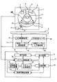
図1に示すように、X線CT装置は、主として、スキャナ1、患者(被検体)テーブル2、操作卓3、患者テーブル2に設けられている天板4、表示装置5、操作装置6等によって構成される。
スキャナ1は、図2に示すように、主として、X線管制御装置7、X線管8(X線源)、コリメータ制御装置9、コリメータ10、X線検出器11、データ収集装置12、回転板13、回転制御装置14、回転板駆動装置15、駆動力伝達系16等によって構成される。
As shown in FIG. 1, the X-ray CT apparatus mainly includes a
As shown in FIG. 2, the
X線管8は、被検体17にX線を照射するものであり、X線を照射するためにX線管8に供給される管電圧・管電流は、X線管制御装置7によって制御される。
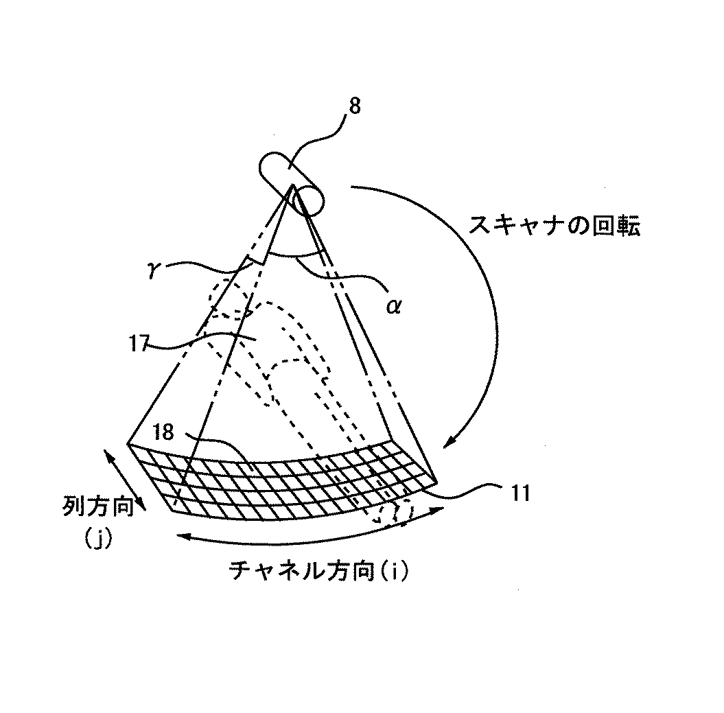
コリメータ10は、X線管8から照射されたX線を、例えば、角錐形のX線ビームすなわちコーンビームX線として被検体17に照射するためにX線照射野を調整するものであり、コリメータ制御装置9によって制御される。
X線検出器11は、図3に示すように、チャネル方向と列方向とに二次元的に設けられた複数のX線検出素子18を備え、X線管8と対向する位置に配置される。X線管8から放射されたX線は、被検体17を透過してX線検出器11に入射する。なお、X線検出器11の構成については、後に詳述する。
データ収集装置12は、X線検出器11に接続されており、X線検出器11の個々のX線検出素子18の検出データを収集するものである。
The
The
As shown in FIG. 3, the
The
回転板13には、上述のX線管制御装置7、X線管8、コリメータ制御装置9、コリメータ10、X線検出器11、データ収集装置12が搭載されている。回転板13は、回転制御装置14によって制御される回転板駆動装置15から、駆動力伝達系16を通じて伝達される駆動力によって回転される。
患者テーブル2は、図2に示すように、主として、天板4、患者テーブル制御装置19、患者テーブル上下動装置20、天板駆動装置21、天板位置センサ25によって構成される。
患者テーブル制御装置19は、天板位置センサ25からの情報を基に患者テーブル上下動装置20を制御して、天板4を適切なテーブル高さに制御する。また、患者テーブル制御装置19は、天板駆動装置21を制御して天板4を前後動させる。これにより、被検体17がスキャナ1のX線照射空間に搬入および搬出される。
On the rotating
As shown in FIG. 2, the patient table 2 mainly includes a top plate 4, a patient
The patient
操作卓3は、図2に示すように、主として、表示装置5、操作装置6、画像再構成装置22、記憶装置23、スキャン計画装置24、システム制御装置26、被曝線量算出装置27によって構成される。
表示装置5は、システム制御装置26に接続されており、画像再構成装置22から出力される再構成画像やシステム制御装置26が取り扱う種々の情報を表示するものである。
操作装置6は、システム制御装置26に接続されており、操作者によって各種の指示、情報等をシステム制御装置26に入力するものである。
操作者は、表示装置5及び操作装置6を使用して、対話的にX線CT装置を操作することができる。
As shown in FIG. 2, the
The
The
The operator can interactively operate the X-ray CT apparatus using the
画像再構成装置22は、システム制御装置26の制御によってスキャナ1内のデータ収集装置12によって収集されたデータが入力され、スキャノグラム撮影時には、データ収集装置12が収集したスキャノグラム投影データ(被検体透視データ)を用いてスキャノグラム画像を作成し、スキャン時には、データ収集装置12が収集した複数ビューの投影データを用いてCT画像(断層像)を再構成するものである。
記憶装置23は、システム制御装置26に接続されており、画像再構成装置22において作成されたスキャノグラム画像、再構成されたCT画像、各種データ、およびX線CT装置の機能を実現するためのプログラム等を格納するものである。
The
The
スキャン計画装置24は、システム制御装置26に接続されており、操作装置6から入力された指示と記憶装置23から読み出されたスキャノグラム画像を用いて、操作者がスキャンの事前計画を作成するものである。すなわち、記憶装置23から読み出されたスキャノグラム画像が表示装置5に表示され、操作者は表示された被検体スキャノグラム画像上で操作装置6を用いてCT画像の再構成位置(以下、「スライス位置」という。)の座標を指定することにより、スライス位置の計画を立てることができる。更に、ここで計画したスライス位置の情報は記憶装置23に保存され、スキャン計画装置24によってX線制御条件等の計画を立てるためにも用いられる。
The
システム制御装置26は、スキャナ1と患者テーブル2とに接続されており、スキャナ1内のX線管制御装置7、コリメータ制御装置9、データ収集装置12、および回転制御装置14を制御し、また、患者テーブル2内の患者テーブル制御装置19を制御するものである。
The
被曝線量算出装置27は、システム制御装置26に接続されており、X線検出器11において検出された被検体17の計測データから、被検体17の被曝線量を算出するものである。被検体17の被曝線量を算出する方法については、後に詳述する。
The exposure
ここで、X線検出器11について詳細に説明する。図3に示すように、X線検出器11は、例えばシンチレータとフォトダイオードとの組み合わせによって構成される複数のX線検出素子18をチャネル方向と列方向(スライス方向)とに二次元的に配列した構成となっている。
X線検出素子18は、全体として円筒面状もしくはチャンネル方向に関して折れ線状に湾曲したX線入射面を構成しており、チャネル番号iは例えば1〜1000程度(すなわち、X線検出素子18がチャネル方向に1〜1000程度配設されている。)、列番号jは例えば1〜320程度(すなわち、X線検出素子18が列方向に1〜320程度配設されている。)である。
図3、図4に示すように、コリメータ10の開口幅によりファン角度αとコーン角度γを調整したコーンビームX線が、患者テーブル2の天板4に載せられてスキャナ1の開口部に搬入された被検体17に照射される。これに対して、X線検出器11は被検体17を透過したX線を検出する。
Here, the
The
As shown in FIGS. 3 and 4, the cone beam X-ray adjusted in the fan angle α and the cone angle γ by the opening width of the
次に、図5を参照しながら、X線CT装置の処理の流れについて説明する。以下の処理は、システム制御装置26の制御下で行われる。なお、ここでは非らせんスキャンを想定して説明を行うが、本発明の実施の形態は、非らせんスキャンに限られるものでなく、らせんスキャンについても適用可能である。らせんスキャンに適用する場合の特別な処理については、後に詳述する。
Next, a processing flow of the X-ray CT apparatus will be described with reference to FIG. The following processing is performed under the control of the
まず、操作者が操作装置6を操作することによって、スキャノグラムの撮影を実施するか否かをシステム制御装置26に対して指示し、その指示に基づいて以下の処理が決定される(ステップS10)。
First, the operator operates the
スキャノグラムの撮影を実施する場合(ステップS10のYES)、スキャノグラムデータを用いてスキャン条件を設定する処理(ステップS11〜S12)に進む。すなわち、システム制御装置26の制御の下、被検体のスキャノグラム撮影が行われ(ステップS11)、撮影されたスキャノグラム像を利用して、スキャン計画装置24によってスキャン計画の設定が行われる(ステップS12)。
ここで設定されるスキャン計画とは、例えば、先頭CT画像・末尾CT画像の体軸方向位置、体軸方向におけるCT画像再構成間隔、X線管電圧、X線管電流、スキャン時間(1回転に要する時間)、X線コリメーション条件、再構成フィルター関数の種類、視野サイズ、等の諸条件を指す。
When scanning a scanogram (YES in step S10), the process proceeds to a process of setting scan conditions using scanogram data (steps S11 to S12). That is, scanogram imaging of the subject is performed under the control of the system control device 26 (step S11), and a scan plan is set by the
The scan plan set here is, for example, the position of the head CT image / end CT image in the body axis direction, the CT image reconstruction interval in the body axis direction, the X-ray tube voltage, the X-ray tube current, the scan time (one rotation). Time), X-ray collimation conditions, types of reconstruction filter functions, field size, and the like.
スキャノグラムの撮影を実施しない場合 (ステップS10のNO)、スキャノグラム像が無い状態で、スキャン計画装置24によってスキャン計画の設定が行われる(ステップS13)。
ここで設定されるスキャン計画は、ステップS12で述べたものと同様であるが、それらのうち先頭CT画像・末尾CT画像の体軸方向位置については、図示しない位置決め用の投光器によって基準位置を定めて、基準位置との相対位置によって定めることができるようになっている。
When scanogram imaging is not performed (NO in step S10), a scan plan is set by the
The scan plan set here is the same as that described in step S12, but the position of the head CT image and the tail CT image in the body axis direction is determined by a positioning projector (not shown). Thus, it can be determined by the relative position to the reference position.
スキャン計画の設定がなされたら、スキャンが行われる(ステップS14〜S23)。
まず、患者テーブル制御装置19が、所定の体軸方向初期位置に天板4を移動させる(ステップS14)。
次に、システム制御装置26の制御の下、所定の体軸方向位置において、スキャンが行われる(ステップS15)。
When the scan plan is set, scanning is performed (steps S14 to S23).
First, the patient
Next, a scan is performed at a predetermined position in the body axis direction under the control of the system control device 26 (step S15).
次に、各種の補正・変換処理(ステップS16〜S18)について説明する。
スキャンで得られた被検体17の計測データに対し、画像再構成装置22が、X線無照射時のデータ収集装置12からの出力(オフセット出力)を、被検体計測時のデータ収集装置12からの出力から差し引くオフセット補正処理を行い(ステップS16)、X線検出器素子18の感度ばらつきを補正する感度ばらつき補正処理を行い(ステップS17)、補正後の計測データをX線透過経路におけるX線吸収係数積分値に比例した投影データに変換するLog変換処理を行う(ステップS18)。
なお、被検体17の投影データを作成するための計測データに対する各種の補正・変換処理(ステップS16〜S18)によって作成されたデータは、CT画像の再構成処理(ステップS19〜S20)のために用いられる。その後、その再構成データは、被曝線量算出装置27による被曝線量算出処理(ステップS21)に利用される。
Next, various correction / conversion processes (steps S16 to S18) will be described.
For the measurement data of the subject 17 obtained by scanning, the
The data created by various correction / conversion processes (steps S16 to S18) for the measurement data for creating the projection data of the subject 17 is used for the CT image reconstruction process (steps S19 to S20). Used. Thereafter, the reconstructed data is used for the dose calculation processing (step S21) by the
次に、CT画像の再構成処理(ステップS19〜S20)について説明する。
ステップS18において作成された被検体17の投影データに対し、画像再構成装置22が、ぼけ補正のための再構成フィルタリング処理を行なう(ステップS19)。そして、画像再構成装置22が、再構成フィルタリング処理後の投影データを逆投影することにより、被検体17の体軸方向所定位置におけるCT画像を再構成する(ステップS20)。
Next, CT image reconstruction processing (steps S19 to S20) will be described.
The
次に、被曝線量算出装置27が、画像データの再構成処理(ステップS19〜S20)によって作成されたデータを解析し、被曝線量の算出処理を行なう(ステップS21)。なお、被曝線量の算出処理については、後に詳述する。
次に、ステップS20において再構成されたCT画像が、ステップS21において算出された被曝線量や、他のスキャン条件等の付帯情報と共に記憶装置24に格納されるとともに、表示装置5に表示される(ステップS22)。表示例については、後に詳述する。
Next, the exposure
Next, the CT image reconstructed in step S20 is stored in the
次に、システム制御装置26によって、全スキャン終了したか否かが判断される(ステップS23)。
全スキャン終了している場合(ステップS23のYES)、一連の処理を終了する。
全スキャン終了していない場合(ステップS23のNO)、患者テーブル制御装置19が、体軸方向の次の天板位置へ天板4を移動させる(ステップS24)。その後、再度スキャンを実行する(ステップS15)。このように、必要な分だけスキャンが繰り返され、一連の処理が終了する。
Next, the
If all scans have been completed (YES in step S23), a series of processing is terminated.
If all scans have not been completed (NO in step S23), the patient
以下、図6〜図12を参照しながら、被曝線量算出処理について、詳細に説明する。
被曝線量算出装置27は、予め、少なくとも、ファントム半径rn(ファントムサイズ情報)、及び、コリメーション幅(最小画像スライス厚M(mm)×列数R:画像スライス厚情報)ごとに、ファントムに対する被曝線量の測定結果に基づいて画像1枚あたりのCTDI(単位被曝線量)を算出し、記憶装置23に単位被曝線量テーブルとして記憶しておく。
Hereinafter, the exposure dose calculation processing will be described in detail with reference to FIGS.
The exposure
そして、スキャンの実行後、被曝線量算出装置27は、計測データに基づいて、被検体17の体軸に垂直な断面の2次元画像を、撮影範囲全体に亘って所定間隔ごとに作成する。例えば、被曝線量算出装置27は、N枚の最小画像スライス厚の2次元画像群を作成する。
次に、被曝線量算出装置27は、2次元画像ごとに、被検体17のCT値を有する画素の集合である被検体領域を検出し、被検体領域の面積を算出し、被検体領域を円形近似した場合の半径(被検体領域のサイズ情報)を求める。
次に、被曝線量算出装置27は、2次元画像ごとに、被検体領域のサイズ情報に対応するファントムサイズ情報、及び、所定間隔に対応する画像スライス厚情報を検索することによって単位被曝線量を特定し、更に、全ての2次元画像に対する単位被曝線量を合算することによって、被検体17の総被曝線量を算出する。
尚、らせんスキャンの場合は、計測データを得るための撮影条件として設定された画像スライス厚と同じ間隔にて作成された2次元画像群を使用する。
After execution of the scan, the exposure
Next, the exposure
Next, the exposure
In the case of spiral scanning, a two-dimensional image group created at the same interval as the image slice thickness set as the imaging condition for obtaining measurement data is used.
図6に示す処理は、被曝線量算出装置27によって行われる。
まず、被曝線量算出装置27は、ステップS20において作成されたN枚の最小画像スライス厚の2次元画像群から各画像において被検体領域を検出する(ステップS31)。被検体領域は、CT値の閾値を定めて検出する。
The process shown in FIG. 6 is performed by the exposure
First, the exposure
ここで、閾値の説明を行う。X線照射経路には、大きく分けると、空気、被検体17が存在する。X線は被検体17を透過する際に吸収されるが、空気では吸収されない。ステップS20において作成される画像データは、CT値として、空気と被検体17の差がはっきりと表されている。そこで、2次元画像に含まれる空気のCT値(-1000HU付近)から閾値Aを設定する。例えば、閾値Aを-800HU程度とする。そして、閾値Aよりも高いCT値の領域は、X線吸収を行うと判断して「1」、閾値Aよりも低いCT値の領域はX線吸収が無いと判断して「0」というように2値化することによって、被検体領域を検出する。 Here, the threshold value will be described. The X-ray irradiation path roughly includes air and the subject 17. X-rays are absorbed when passing through the subject 17 but are not absorbed by air. In the image data created in step S20, the difference between air and the subject 17 is clearly expressed as a CT value. Therefore, the threshold value A is set from the CT value of air included in the two-dimensional image (around −1000 HU). For example, the threshold A is set to about −800 HU. A region having a CT value higher than the threshold value A is determined to perform X-ray absorption, and “1” is determined. A region having a CT value lower than the threshold value A is determined to have no X-ray absorption, and is set to “0”. By subjecting to binarization, the subject region is detected.
また、X線照射経路には、天板4も存在する。そこで、天板4の影響を除くために、天板4のCT値に基づいて閾値を設けても良い。天板4は、人を支えるためのものであるから、空気のCT値に近い(X線吸収量の小さい)材料を使用している。一方、天板4を除去するための閾値は、被検体17において最もCT値が小さい脂肪のCT値(-100HU付近)よりも小さいCT値とする必要がある。そこで、天板4を除去するための閾値は、−1000<天板CT値<−100の範囲とすれば良い。
また、被検体領域を検出する為の手法は、様々な文献において報告されており(例えば、特開2007-181623号公報)、本手法に限らず既知の手法を利用しても構わない。
Moreover, the top plate 4 also exists in the X-ray irradiation path. Therefore, a threshold value may be provided based on the CT value of the top plate 4 in order to eliminate the influence of the top plate 4. Since the top plate 4 is for supporting a person, a material close to the CT value of air (small X-ray absorption amount) is used. On the other hand, the threshold value for removing the top 4 needs to be a CT value smaller than the CT value of fat having the smallest CT value in the subject 17 (near -100HU). Therefore, the threshold value for removing the top 4 may be in the range of −1000 <top CT value <−100.
In addition, methods for detecting a subject region have been reported in various documents (for example, Japanese Patent Application Laid-Open No. 2007-181623), and not only this method but also a known method may be used.
次に、被曝線量算出装置27は、2次元画像群の各々から検出した被検体領域の面積Snを算出する(ステップS32)。
2次元画像群中のn枚目の画像における被検体領域の面積算出処理について、図7を用いて説明する。図7では、n枚目の2次元画像30をピクセルごとに簡易的に図示している。2次元画像30は、X方向とY方向それぞれに、例えば512×512ピクセル表示しており、空気領域32には「0」、被検体領域31には「1」のピクセル値となっている。
例えば、被曝線量算出装置27は、2次元画像30のFOVサイズD[mm]から1ピクセルあたりの面積を算出し、「1」のピクセル値を持つ総ピクセル数Tnを乗算することによって(次式参照)、被検体領域31の面積を求める。
Next, the exposure
The area calculation process of the subject region in the nth image in the two-dimensional image group will be described with reference to FIG. In FIG. 7, the n-th two-dimensional image 30 is simply illustrated for each pixel. The two-dimensional image 30 displays, for example, 512 × 512 pixels in each of the X direction and the Y direction, and has a pixel value of “0” in the air region 32 and “1” in the
For example, the exposure
尚、ここでは、512×512ピクセル表示として説明したが、これに限定されるものではない。
次に、被曝線量算出装置27は、求めたSnから被検体17の断層像を円形に近似し、次式によって半径rnを求める(ステップS33)。
In addition, although it demonstrated as a 512x512 pixel display here, it is not limited to this.
Next, the exposure
尚、2次元画像30における被検体領域31の面積を求める手法は、様々な文献において報告されており(例えば2007-181623号公報)、本手法に限らず既知の手法を利用しても構わない。
A method for obtaining the area of the
次に、被曝線量算出装置27は、単位被曝線量テーブルから、ステップS33において求められる半径rnに相当する単位被曝線量を選択する(ステップS34)。
Next, the
ここで、単位被曝線量テーブルについて説明する。単位被曝線量テーブルは、数種類の異なる半径のアクリルファントムを用いて計測したCTDI値から、画像単位のCTDI値に換算したテーブルである。本発明のX線CT装置の記憶装置23には、予め半径の異なる複数のアクリルファントムを用いたCTDI値が記憶されているものとする。
Here, the unit dose table will be described. The unit dose table is a table in which CTDI values measured using acrylic phantoms having several different radii are converted into CTDI values in image units. It is assumed that the
以下では、説明を簡略化する為に、半径r1mm、r2mm、・・・、r8mmの8つのアクリルファントムを使用した場合を記述する。当然ながら、ファントムの大きさ及び数は、適宜変更可能である。
また、単位被曝線量テーブルに登録されるCTDI値は、コリメーション幅別に計測したCTDI値を最小画像スライス厚M[mm]相当になるように、そのコリメーション幅における最大列数Rによって除算した値を用いている。
ここで、最小画像スライス厚Mとは、X線CT装置において撮影可能な最小の画像スライス厚、すなち、撮影条件の画像スライス厚として設定可能な最小値である。コリメーション幅とは、コリメータ10の列方向(図3参照)の開口幅のことである。コリメーション幅における最大列数Rとは、コーン角度γ(図3参照)を調整したコーンビームX線を検出するX線検出素子18の列方向の最大個数のことである。
例えば、X線CT装置が64列装置(X線検出素子18が列方向に64個配列される装置)であって、コリメーション幅が、最小画像スライス厚M[mm]×列数64個の場合、画像1枚あたりのCTDI値=計測されたCTDI値/64と算出される。
Hereinafter, in order to simplify the description, a case where eight acrylic phantoms having radii r1 mm, r2 mm,..., R8 mm are used will be described. Of course, the size and number of phantoms can be changed as appropriate.
The CTDI value registered in the unit dose table uses a value obtained by dividing the CTDI value measured for each collimation width by the maximum number of columns R in the collimation width so as to correspond to the minimum image slice thickness M [mm]. ing.
Here, the minimum image slice thickness M is the minimum image slice thickness that can be imaged by the X-ray CT apparatus, that is, the minimum value that can be set as the image slice thickness of the imaging conditions. The collimation width is the opening width of the
For example, when the X-ray CT apparatus is a 64 column apparatus (an apparatus in which 64
図8に示す単位被曝線量テーブル40では、管電圧、コリメーション幅(最小画像スライス厚M×列数R)、及び、ファントム半径ごとに、画像1枚あたりのCTDI値が登録されている。
例えば、左から1番目の表には、管電圧41aが「○○KV」、及び、コリメーション幅42aが「最小画像スライス厚M(mm)×R1」の撮影条件によって、ファントムの半径44が「r1〜r8」(ファントム名43が「円形ファントム1〜円形ファントム8」)を用いて計測した8個のCTDI値「CTDI−a1〜CTDI−a8」を列数R1によって除した値が、それぞれ、ファントムの半径44に対応付けられて、画像1枚あたりのCTDI45「CTDI−a1/R1〜CTDI−a8/R1」として登録されている。
また、例えば、左から2番目の表には、管電圧41aが「○○KV」、及び、コリメーション幅42bが「最小画像スライス厚M(mm)×R2」の撮影条件によって、ファントムの半径44が「r1〜r8」を用いて計測した8個のCTDI値「CTDI−a9〜CTDI−a16」を列数R2によって除した値が、それぞれ、ファントムの半径44に対応付けられて、画像1枚あたりのCTDI45「CTDI−a9/R2〜CTDI−a16/R2」として登録されている。
また、例えば、左から3番目の表には、管電圧41bが「△△KV」、及び、コリメーション幅42aが「最小画像スライス厚M(mm)×R1」の撮影条件によって、ファントムの半径44が「r1〜r8」を用いて計測した8個のCTDI値「CTDI−b1〜CTDI−b8」を列数R1によって除した値が、それぞれ、ファントムの半径44に対応付けられて、画像1枚あたりのCTDI45「CTDI−b1/R1〜CTDI−b8/R1」として登録されている。
In the unit dose table 40 shown in FIG. 8, CTDI values per image are registered for each tube voltage, collimation width (minimum image slice thickness M × number of columns R), and phantom radius.
For example, in the first table from the left, the
Further, for example, in the second table from the left, the
Further, for example, in the third table from the left, the
尚、単位被曝線量テーブル40は、少なくとも、ファントムの半径(ファントムサイズ情報)及びコリメーション幅(最小画像スライス厚M(mm)×列数R:画像スライス厚情報)ごとに、画像1枚あたりのCTDIが登録されていれば良い。更に、図8に示すように、管電圧やその他の線質を変化させるパラメータごとに、画像1枚あたりのCTDIが登録されていることによって、被検体の実被曝線量を高精度に算出することができる。 The unit dose table 40 includes a CTDI per image at least for each phantom radius (phantom size information) and collimation width (minimum image slice thickness M (mm) × number of columns R: image slice thickness information). As long as is registered. Furthermore, as shown in FIG. 8, the CTDI per image is registered for each parameter that changes the tube voltage and other radiation qualities, so that the actual exposure dose of the subject can be calculated with high accuracy. Can do.
ステップS33において求められる半径rnと、単位被曝線量テーブル40に登録されているファントムの半径44との対応付けは、図9の判定式52によって定める。
例えば、rn≦(r1+r2)/2の場合、使用ファントム径51がr1となる。また、例えば、(r1+r2)/2<rn≦(r2+r3)/2の場合、使用ファントム径51がr2となる。以下、同様である。
被曝線量算出装置27は、このように使用ファントム径51を定めて、単位被曝線量テーブル40から、画像1枚あたりのCTDI45を特定し、n枚目の画像の被曝線量CTDInとする。
The correspondence between the radius rn obtained in step S33 and the
For example, when rn ≦ (r1 + r2) / 2, the used
The exposure
被曝線量算出装置27は、ステップS35において被曝線量CTDInを加算し、全ての画像に対してステップS31〜ステップS35を繰り返す(ステップS36)。
すなわち、被曝線量算出装置27は、次式の通り、総被曝線量を算出する(ステップS37)。
The exposure
That is, the exposure
図10では、被曝線量の表示例を示している。図10(a)は、被検体17の上面図、図10(b)は、被検体17の側面図、図10(c)は、領域ごとの被曝線量(CTDI値)、図10(d)は、体軸方向の形状変化に伴う使用ファントム径(mm)の変化を図示している。 FIG. 10 shows a display example of the exposure dose. 10A is a top view of the subject 17, FIG. 10B is a side view of the subject 17, FIG. 10C is an exposure dose (CTDI value) for each region, and FIG. 10D. These show the change of the use phantom diameter (mm) accompanying the shape change of a body-axis direction.
被曝線量算出装置27は、2次元画像ごとに被曝線量を算出していることから、図10(c)に示すように、体軸方向の任意の領域ごとに被曝線量を計算し、表示することができる。
Since the exposure
図10(d)のグラフは、被検体17の体軸方向の位置を横軸、被曝線量算出装置27によって特定される使用ファントム径(ファントムのサイズ情報)を縦軸としている。
これまでIEC60601-2-44によって規定される基準のファントムは、図10(d)に示すように、頭部領域(半径80mm)と体幹部領域(半径160mm)の2種類のみ使用しており、体軸方向の形状変化を考慮することができなかった。一方、本発明では、図10(d)に示すように、被曝線量を求める際に体軸方向の画像毎に被検体の面積をアクリルファントム半径相当に換算して体軸方向の被検体の形状変化を考慮した被曝線量を表現することができる。
In the graph of FIG. 10D, the horizontal axis indicates the position of the subject 17 in the body axis direction, and the phantom diameter (phantom size information) specified by the exposure
Up to now, the reference phantom defined by IEC 60601-2-44 has used only two types of head region (radius 80 mm) and trunk region (radius 160 mm) as shown in FIG. The shape change in the body axis direction could not be considered. On the other hand, in the present invention, as shown in FIG. 10 (d), when determining the exposure dose, the area of the subject is converted into an acrylic phantom radius equivalent for each image in the body axis direction, and the shape of the subject in the body axis direction is calculated. It is possible to express the exposure dose considering changes.
従来、肥満体の患者に対して、読影に適した画像を撮影するための撮影条件を決定することが非常に困難であった。これに対して、図10(d)に示す縦軸を使用ファントム径としたグラフは、次回の撮影において撮影条件を決定する際に参考となる情報である。なぜなら、ファントムによる計測結果は、撮影条件及び画質の良否が予め分かっていることから、被検体の体型をファントムに近似して考えることができれば、読影に適した画像を撮影するための撮影条件も容易に判断できるからである。 Conventionally, it has been very difficult to determine photographing conditions for photographing an image suitable for interpretation in obese patients. On the other hand, the graph with the phantom diameter used as the vertical axis shown in FIG. 10D is information that is helpful when determining the shooting conditions in the next shooting. Because the measurement results by the phantom are known in advance as to the imaging conditions and the quality of the image quality, if the body shape of the subject can be approximated to a phantom, the imaging conditions for capturing an image suitable for interpretation are also available. This is because it can be easily judged.
尚、図10(d)のグラフでは、縦軸を使用ファントム径としたが、縦軸を被曝線量算出装置27によって特定される画像1枚あたりのCTDI(単位被曝線量)としても良い。縦軸を単位被曝線量とすることによって、画像単位の詳細な被曝状況が分かる。
In the graph of FIG. 10D, the phantom diameter is the vertical axis, but the vertical axis may be CTDI (unit dose) per image specified by the
本発明の実施の形態によれば、体軸方向の被検体の形状変化を考慮した被曝線量を求めることが可能であることから、被曝線量を精度良く算出することが可能となる。更に、スキャノグラム撮影の計測データではなく、本スキャンの計測データに基づいて被検体領域のサイズ情報を算出し、その被検体領域のサイズ情報に基づいて被曝線量を求めていることから、本スキャンにおける撮影態様が正確に考慮されたものとなっている。 According to the embodiment of the present invention, since it is possible to obtain the exposure dose in consideration of the shape change of the subject in the body axis direction, the exposure dose can be calculated with high accuracy. Further, since the size information of the subject region is calculated based on the measurement data of the main scan, not the measurement data of the scanogram imaging, and the exposure dose is obtained based on the size information of the subject region, The photographing mode is accurately taken into consideration.
尚、前述の説明では、体軸方向の被曝線量計算をより精度良く算出するために、単位被曝線量テーブルには、最小画像スライス厚に基づく単位被曝線量を登録するものとしたが、最小画像スライス厚を数枚加算したような厚い画像スライス厚に基づく単位被曝線量を登録するものとしても良い。
また、前述の説明では、円形ファントムを前提として、被検体17の断層像を円形に近似し、半径rnを求めることとしたが、楕円形ファントムを前提として、被検体17の断層像を楕円形に近似しても良い。
In the above description, in order to calculate the dose calculation in the body axis direction with higher accuracy, the unit dose based on the minimum image slice thickness is registered in the unit dose table. The unit exposure dose based on a thick image slice thickness obtained by adding several thicknesses may be registered.
In the above description, the tomographic image of the subject 17 is approximated to be circular and the radius rn is obtained on the premise of the circular phantom. However, on the premise of the elliptical phantom, the tomographic image of the subject 17 is elliptical. May be approximated.
<変形例1>
らせんスキャンに適用する場合の特別な処理について説明する。
らせんスキャンでは長いらせん状の軌跡の何処からでも画像再構成が可能であり、多くの画像を再構成することができる。ただし、この場合、一枚一枚の持つスライス厚はコリメーション、ヘリカルピッチによるものであり、画像再構成間隔を細かくすることによりオーバーラップした画像が得られる。
<
A special process when applied to the helical scan will be described.
In the helical scan, image reconstruction can be performed from anywhere in a long spiral locus, and many images can be reconstructed. However, in this case, the slice thickness of each sheet is due to collimation and helical pitch, and overlapping images can be obtained by reducing the image reconstruction interval.
図11に示すように、らせんスキャンによって取得される計測データに基づく2次元画像(らせんスキャン画像)は、画像スライス厚と同じ画像再構成間隔にて作成した画像であれば、互いにオーバーラップした領域がない。
一方、画像スライス厚よりも画像再構成間隔を細かくすることによって、らせんスキャン画像は、互いにオーバーラップした画像となる。
従って、画像再構成間隔が画像スライス厚よりも細かくして2次元画像を作成する場合、被曝線量算出装置27によって算出される総被曝線量は、実際の被曝線量よりもかさ増しして計算することになってしまう。
そこで、らせんスキャンの場合は、被曝線量算出装置27は、計測データを得るための撮影条件として設定された画像スライス厚と同じ間隔にて作成された2次元画像群を使用し、被曝線量を算出する。
As shown in FIG. 11, if a two-dimensional image (helical scan image) based on measurement data acquired by a helical scan is an image created at the same image reconstruction interval as the image slice thickness, the regions overlap each other. There is no.
On the other hand, by making the image reconstruction interval finer than the image slice thickness, the spiral scan images become images that overlap each other.
Therefore, when a two-dimensional image is created with the image reconstruction interval being smaller than the image slice thickness, the total exposure dose calculated by the exposure
Therefore, in the case of a spiral scan, the
<変形例2>
前述の説明では、図9の判定式52を用いて、単位被曝線量を特定したが、本発明の実施の形態はこの例に限定されない。
変形例2では、予め半径の異なる複数のアクリルファントムから、アクリルファントムの半径とCTDIの相関式を算出し、その相関式から被検体の総被曝線量を算出するものである。
<
In the above description, the unit exposure dose is specified using the
In the second modification, a correlation formula between the acrylic phantom radius and CTDI is calculated from a plurality of acrylic phantoms having different radii in advance, and the total exposure dose of the subject is calculated from the correlation formula.
図11には、ファントム半径とCTDIの関係式60が示されている。図11に示すように、ファントム半径が大きくなると被曝線量が小さくなることがわかる。そこで、この時のファントム半径と被曝線量の相関式を作ることにより、測定したファントム半径に捉われず、被曝線量を求めることができる。この時の相関式は次式によって表せる。 FIG. 11 shows a relational expression 60 between the phantom radius and CTDI. As shown in FIG. 11, it can be seen that the exposure dose decreases as the phantom radius increases. Therefore, by creating a correlation formula between the phantom radius and the exposure dose at this time, the exposure dose can be obtained without being caught by the measured phantom radius. The correlation equation at this time can be expressed by the following equation.
但し、Z:係数、r:アクリル半径、k:測定ファントム数(k≧2)である。
この時の測定ファントム数は、数が多いほど望ましい。また、相関式は、少なくとも2つ以上のファントムの測定を必要とする。
単位被曝線量算出装置27は、ここで求めた相関式に基づいて使用ファントム径、画像1枚あたりCTDI(単位被曝線量)を算出する。
この例では、最小画像スライス厚の画像1枚あたりのCTDI値がアクリルファントム数に限定されずに算出できるため、前述の例よりも正確な総被曝線量を求めることができる。
However, Z: coefficient, r: acrylic radius, k: number of measurement phantoms (k ≧ 2).
At this time, the larger the number of measurement phantoms, the better. The correlation equation also requires measurement of at least two or more phantoms.
The unit
In this example, since the CTDI value per image having the minimum image slice thickness can be calculated without being limited to the number of acrylic phantoms, the total exposure dose can be determined more accurately than in the above example.
以上、添付図面を参照しながら、本発明に係るX線CT装置等の好適な実施形態について説明したが、本発明はかかる例に限定されない。当業者であれば、本願で開示した技術的思想の範疇内において、各種の変更例又は修正例に想到し得ることは明らかであり、それらについても当然に本発明の技術的範囲に属するものと了解される。 The preferred embodiments of the X-ray CT apparatus and the like according to the present invention have been described above with reference to the accompanying drawings, but the present invention is not limited to such examples. It will be apparent to those skilled in the art that various changes or modifications can be conceived within the scope of the technical idea disclosed in the present application, and these naturally belong to the technical scope of the present invention. Understood.
1………スキャナ
2………患者テーブル
3………操作卓
4………天板
6………表示装置
6………操作装置
7………X線管制御装置
8………X線管
9………コリメータ制御装置
10………コリメータ
11………X線検出器
12………データ収集装置
13………回転板
14………回転制御装置
16………回転板駆動装置
16………駆動力伝達系
17………被検体
18………X線検出素子
19………患者テーブル制御装置
20………患者テーブル上下動装置
21………天板駆動装置
22………画像再構成装置
23………記憶装置
24………スキャン計画装置
26………天板位置センサ
26………システム制御装置
27………被曝線量算出装置
DESCRIPTION OF
Claims (3)
ファントムサイズ情報及び画像スライス厚情報ごとに、ファントムに対する被曝線量の測定結果に基づいて算出される単位被曝線量を記憶する記憶手段と、
前記計測データに基づいて、前記被検体の体軸に垂直な断面の2次元画像を、撮影範囲全体に亘って所定間隔ごとに作成する画像作成手段と、
前記2次元画像ごとに、被検体のCT値を有する画素の集合である被検体領域を検出し、前記被検体領域のサイズ情報を算出するサイズ情報算出手段と、
前記2次元画像ごとに、前記被検体領域のサイズ情報に対応する前記ファントムサイズ情報、及び、前記所定間隔に対応する前記画像スライス厚情報を検索することによって前記単位被曝線量を特定し、更に、全ての前記2次元画像に対する前記単位被曝線量を合算することによって、前記被検体の総被曝線量を算出する被曝量算出手段と、
を具備することを特徴とするX線CT装置。 Equipped with an X-ray source for irradiating a subject with X-rays, an X-ray detector arranged to face the X-ray source and detecting X-rays transmitted through the subject, and the X-ray source and the X-ray detector An image reconstructing device that acquires measurement data detected by the scanner that rotates around the subject and the X-ray detector and reconstructs a tomographic image of the subject, and is reconstructed by the image reconstructing device. An X-ray CT apparatus comprising an image display device for displaying a configured tomogram,
Storage means for storing a unit dose calculated based on a measurement result of the dose to the phantom for each phantom size information and image slice thickness information;
An image creating means for creating a two-dimensional image of a cross section perpendicular to the body axis of the subject at predetermined intervals over the entire imaging range based on the measurement data;
Size information calculation means for detecting a subject region that is a set of pixels having a CT value of the subject for each of the two-dimensional images and calculating size information of the subject region;
For each of the two-dimensional images, the unit dose is specified by searching the phantom size information corresponding to the size information of the subject region and the image slice thickness information corresponding to the predetermined interval, A dose calculation means for calculating a total dose of the subject by adding up the unit doses for all the two-dimensional images;
An X-ray CT apparatus comprising:
を更に具備することを特徴とする請求項1又は請求項2に記載のX線CT装置。 A graph with the horizontal axis representing the position of the subject in the body axis direction and the vertical axis representing the unit dose and / or phantom size information identified by the dose calculation means is displayed on the image display device. Display means,
The X-ray CT apparatus according to claim 1, further comprising:
Priority Applications (1)
| Application Number | Priority Date | Filing Date | Title |
|---|---|---|---|
| JP2011010874A JP2012148028A (en) | 2011-01-21 | 2011-01-21 | X-ray ct apparatus |
Applications Claiming Priority (1)
| Application Number | Priority Date | Filing Date | Title |
|---|---|---|---|
| JP2011010874A JP2012148028A (en) | 2011-01-21 | 2011-01-21 | X-ray ct apparatus |
Publications (1)
| Publication Number | Publication Date |
|---|---|
| JP2012148028A true JP2012148028A (en) | 2012-08-09 |
Family
ID=46790907
Family Applications (1)
| Application Number | Title | Priority Date | Filing Date |
|---|---|---|---|
| JP2011010874A Pending JP2012148028A (en) | 2011-01-21 | 2011-01-21 | X-ray ct apparatus |
Country Status (1)
| Country | Link |
|---|---|
| JP (1) | JP2012148028A (en) |
Cited By (5)
| Publication number | Priority date | Publication date | Assignee | Title |
|---|---|---|---|---|
| JP2016202329A (en) * | 2015-04-16 | 2016-12-08 | キヤノンマーケティングジャパン株式会社 | Exposure dose calculation device, exposure dose management system, and control method and program thereof |
| WO2017002571A1 (en) * | 2015-07-02 | 2017-01-05 | 株式会社日立製作所 | X-ray ct device and method for controlling same |
| CN106901768A (en) * | 2017-02-23 | 2017-06-30 | 门阔 | Reduce the self-adaptive modulation method of conical beam CT exposure dose |
| JP2020163062A (en) * | 2019-03-29 | 2020-10-08 | 大日本印刷株式会社 | Mask generation device, three-dimensional re-construction image generation device, mask generation method and program |
| CN116035611A (en) * | 2023-03-27 | 2023-05-02 | 湖南省计量检测研究院 | Novel CT detection method, system and readable storage medium special for coronavirus infection |
Citations (7)
| Publication number | Priority date | Publication date | Assignee | Title |
|---|---|---|---|---|
| JPH11332848A (en) * | 1998-05-25 | 1999-12-07 | Ge Yokogawa Medical Systems Ltd | Slicing position identification method and medical image diagnostic apparatus |
| JP2004073397A (en) * | 2002-08-14 | 2004-03-11 | Ge Medical Systems Global Technology Co Llc | X-ray ct apparatus |
| JP2005058653A (en) * | 2003-08-20 | 2005-03-10 | Ge Medical Systems Global Technology Co Llc | X-ray ct apparatus, information processing method, storage medium and program |
| JP2008113960A (en) * | 2006-11-07 | 2008-05-22 | Ge Medical Systems Global Technology Co Llc | Radiographic apparatus |
| JP2008284021A (en) * | 2007-05-15 | 2008-11-27 | Fujifilm Corp | Method of obtaining body fat percentage |
| JP2010022692A (en) * | 2008-07-23 | 2010-02-04 | Ge Medical Systems Global Technology Co Llc | X-ray ct apparatus |
| JP2010167188A (en) * | 2009-01-26 | 2010-08-05 | Toshiba Corp | Medical image diagnostic apparatus, image data output device, and control program for outputting image data |
-
2011
- 2011-01-21 JP JP2011010874A patent/JP2012148028A/en active Pending
Patent Citations (7)
| Publication number | Priority date | Publication date | Assignee | Title |
|---|---|---|---|---|
| JPH11332848A (en) * | 1998-05-25 | 1999-12-07 | Ge Yokogawa Medical Systems Ltd | Slicing position identification method and medical image diagnostic apparatus |
| JP2004073397A (en) * | 2002-08-14 | 2004-03-11 | Ge Medical Systems Global Technology Co Llc | X-ray ct apparatus |
| JP2005058653A (en) * | 2003-08-20 | 2005-03-10 | Ge Medical Systems Global Technology Co Llc | X-ray ct apparatus, information processing method, storage medium and program |
| JP2008113960A (en) * | 2006-11-07 | 2008-05-22 | Ge Medical Systems Global Technology Co Llc | Radiographic apparatus |
| JP2008284021A (en) * | 2007-05-15 | 2008-11-27 | Fujifilm Corp | Method of obtaining body fat percentage |
| JP2010022692A (en) * | 2008-07-23 | 2010-02-04 | Ge Medical Systems Global Technology Co Llc | X-ray ct apparatus |
| JP2010167188A (en) * | 2009-01-26 | 2010-08-05 | Toshiba Corp | Medical image diagnostic apparatus, image data output device, and control program for outputting image data |
Cited By (8)
| Publication number | Priority date | Publication date | Assignee | Title |
|---|---|---|---|---|
| JP2016202329A (en) * | 2015-04-16 | 2016-12-08 | キヤノンマーケティングジャパン株式会社 | Exposure dose calculation device, exposure dose management system, and control method and program thereof |
| WO2017002571A1 (en) * | 2015-07-02 | 2017-01-05 | 株式会社日立製作所 | X-ray ct device and method for controlling same |
| JPWO2017002571A1 (en) * | 2015-07-02 | 2018-04-05 | 株式会社日立製作所 | X-ray CT apparatus and control method thereof |
| CN106901768A (en) * | 2017-02-23 | 2017-06-30 | 门阔 | Reduce the self-adaptive modulation method of conical beam CT exposure dose |
| JP2020163062A (en) * | 2019-03-29 | 2020-10-08 | 大日本印刷株式会社 | Mask generation device, three-dimensional re-construction image generation device, mask generation method and program |
| JP7230645B2 (en) | 2019-03-29 | 2023-03-01 | 大日本印刷株式会社 | Mask generation device, three-dimensional reconstruction image generation device, mask generation method, and program |
| CN116035611A (en) * | 2023-03-27 | 2023-05-02 | 湖南省计量检测研究院 | Novel CT detection method, system and readable storage medium special for coronavirus infection |
| CN116035611B (en) * | 2023-03-27 | 2023-06-23 | 湖南省计量检测研究院 | Novel CT detection method, system and readable storage medium special for coronavirus infection |
Similar Documents
| Publication | Publication Date | Title |
|---|---|---|
| US7813471B2 (en) | X-ray CT apparatus | |
| JP4822478B2 (en) | X-ray CT system | |
| EP2331945B1 (en) | Method and apparatus to improve ct image acquisition using a displaced geometry | |
| JP5942266B2 (en) | X-ray CT apparatus and tube current determination method | |
| JP5191908B2 (en) | X-ray CT system | |
| JP5455935B2 (en) | X-ray CT apparatus and method | |
| JP4159188B2 (en) | Tube current adjusting method and apparatus, and X-ray CT apparatus | |
| JP2007021217A (en) | Method for generating image in body range of moving living body and x-ray diagnostic equipment | |
| JP2007181623A (en) | X-ray ct apparatus | |
| JP2007054372A (en) | X-ray ct apparatus | |
| JP5406047B2 (en) | X-ray CT system | |
| JP6509198B2 (en) | X-ray CT system | |
| JP2009125250A (en) | X-ray ct equipment | |
| JP2012148028A (en) | X-ray ct apparatus | |
| JP4920256B2 (en) | X-ray CT system | |
| JP5697422B2 (en) | X-ray diagnostic equipment | |
| JP5022690B2 (en) | Radiography equipment | |
| JP4679951B2 (en) | X-ray CT system | |
| JP2008017964A (en) | X-ray ct apparatus | |
| JP2007044496A (en) | X-ray ct apparatus | |
| JP2017131496A (en) | X-ray ct apparatus, photographing condition setup method, and photographing condition setup program | |
| JP2016106814A (en) | Medical image diagnostic apparatus and imaging range display method | |
| JP4648355B2 (en) | Tube current adjusting method and apparatus, and X-ray CT apparatus | |
| JP2006218327A (en) | Radiation imaging apparatus | |
| JP2019004920A (en) | X-ray CT apparatus and X-ray irradiation condition setting method |
Legal Events
| Date | Code | Title | Description |
|---|---|---|---|
| A621 | Written request for application examination |
Free format text: JAPANESE INTERMEDIATE CODE: A621 Effective date: 20131219 |
|
| A977 | Report on retrieval |
Free format text: JAPANESE INTERMEDIATE CODE: A971007 Effective date: 20140819 |
|
| A131 | Notification of reasons for refusal |
Free format text: JAPANESE INTERMEDIATE CODE: A131 Effective date: 20150106 |
|
| A131 | Notification of reasons for refusal |
Free format text: JAPANESE INTERMEDIATE CODE: A131 Effective date: 20150707 |
|
| A02 | Decision of refusal |
Free format text: JAPANESE INTERMEDIATE CODE: A02 Effective date: 20151110 |