JP5183998B2 - Tapered roller bearing - Google Patents
Tapered roller bearing Download PDFInfo
- Publication number
- JP5183998B2 JP5183998B2 JP2007202084A JP2007202084A JP5183998B2 JP 5183998 B2 JP5183998 B2 JP 5183998B2 JP 2007202084 A JP2007202084 A JP 2007202084A JP 2007202084 A JP2007202084 A JP 2007202084A JP 5183998 B2 JP5183998 B2 JP 5183998B2
- Authority
- JP
- Japan
- Prior art keywords
- tapered roller
- diameter
- inner ring
- cage
- hook
- Prior art date
- Legal status (The legal status is an assumption and is not a legal conclusion. Google has not performed a legal analysis and makes no representation as to the accuracy of the status listed.)
- Expired - Fee Related
Links
- 229920005989 resin Polymers 0.000 claims description 17
- 239000011347 resin Substances 0.000 claims description 17
- 230000005540 biological transmission Effects 0.000 claims description 9
- 230000007935 neutral effect Effects 0.000 claims description 7
- 239000002184 metal Substances 0.000 claims description 3
- 229910052751 metal Inorganic materials 0.000 claims description 3
- 239000004734 Polyphenylene sulfide Substances 0.000 description 13
- 229920000069 polyphenylene sulfide Polymers 0.000 description 13
- 239000000463 material Substances 0.000 description 11
- 229920006351 engineering plastic Polymers 0.000 description 10
- XEEYBQQBJWHFJM-UHFFFAOYSA-N Iron Chemical compound [Fe] XEEYBQQBJWHFJM-UHFFFAOYSA-N 0.000 description 8
- 230000004323 axial length Effects 0.000 description 7
- 238000005242 forging Methods 0.000 description 7
- UHOVQNZJYSORNB-UHFFFAOYSA-N Benzene Chemical group C1=CC=CC=C1 UHOVQNZJYSORNB-UHFFFAOYSA-N 0.000 description 6
- 229910000831 Steel Inorganic materials 0.000 description 5
- -1 high temperature Substances 0.000 description 5
- 239000003921 oil Substances 0.000 description 5
- 239000010959 steel Substances 0.000 description 5
- 238000004132 cross linking Methods 0.000 description 4
- 229910052742 iron Inorganic materials 0.000 description 4
- 238000000465 moulding Methods 0.000 description 4
- 238000010348 incorporation Methods 0.000 description 3
- 238000004904 shortening Methods 0.000 description 3
- 239000000126 substance Substances 0.000 description 3
- 229920003002 synthetic resin Polymers 0.000 description 3
- 239000000057 synthetic resin Substances 0.000 description 3
- 229920000106 Liquid crystal polymer Polymers 0.000 description 2
- 239000004977 Liquid-crystal polymers (LCPs) Substances 0.000 description 2
- 239000004696 Poly ether ether ketone Substances 0.000 description 2
- 239000004693 Polybenzimidazole Substances 0.000 description 2
- 239000004697 Polyetherimide Substances 0.000 description 2
- 239000004954 Polyphthalamide Substances 0.000 description 2
- NINIDFKCEFEMDL-UHFFFAOYSA-N Sulfur Chemical compound [S] NINIDFKCEFEMDL-UHFFFAOYSA-N 0.000 description 2
- 239000004699 Ultra-high molecular weight polyethylene Substances 0.000 description 2
- 238000005452 bending Methods 0.000 description 2
- 239000010960 cold rolled steel Substances 0.000 description 2
- 230000006866 deterioration Effects 0.000 description 2
- 230000000694 effects Effects 0.000 description 2
- 239000003365 glass fiber Substances 0.000 description 2
- 238000007654 immersion Methods 0.000 description 2
- 239000010687 lubricating oil Substances 0.000 description 2
- 238000000034 method Methods 0.000 description 2
- 230000002093 peripheral effect Effects 0.000 description 2
- 125000001997 phenyl group Chemical group [H]C1=C([H])C([H])=C(*)C([H])=C1[H] 0.000 description 2
- 229920006111 poly(hexamethylene terephthalamide) Polymers 0.000 description 2
- 229920002492 poly(sulfone) Polymers 0.000 description 2
- 229920001230 polyarylate Polymers 0.000 description 2
- 229920002480 polybenzimidazole Polymers 0.000 description 2
- 229920001707 polybutylene terephthalate Polymers 0.000 description 2
- 229920002530 polyetherether ketone Polymers 0.000 description 2
- 229920001601 polyetherimide Polymers 0.000 description 2
- 229920000139 polyethylene terephthalate Polymers 0.000 description 2
- 239000005020 polyethylene terephthalate Substances 0.000 description 2
- 229920000642 polymer Polymers 0.000 description 2
- 238000006116 polymerization reaction Methods 0.000 description 2
- 229920006324 polyoxymethylene Polymers 0.000 description 2
- 229920006375 polyphtalamide Polymers 0.000 description 2
- 229910052717 sulfur Inorganic materials 0.000 description 2
- 239000011593 sulfur Substances 0.000 description 2
- 229920006259 thermoplastic polyimide Polymers 0.000 description 2
- 229920000785 ultra high molecular weight polyethylene Polymers 0.000 description 2
- 229920003189 Nylon 4,6 Polymers 0.000 description 1
- 229920002292 Nylon 6 Polymers 0.000 description 1
- 229920002302 Nylon 6,6 Polymers 0.000 description 1
- 229920012266 Poly(ether sulfone) PES Polymers 0.000 description 1
- 229930182556 Polyacetal Natural products 0.000 description 1
- 239000004952 Polyamide Substances 0.000 description 1
- 229920012310 Polyamide 9T (PA9T) Polymers 0.000 description 1
- 101100304647 Saccharomyces cerevisiae (strain ATCC 204508 / S288c) RPL39 gene Proteins 0.000 description 1
- JUPQTSLXMOCDHR-UHFFFAOYSA-N benzene-1,4-diol;bis(4-fluorophenyl)methanone Chemical compound OC1=CC=C(O)C=C1.C1=CC(F)=CC=C1C(=O)C1=CC=C(F)C=C1 JUPQTSLXMOCDHR-UHFFFAOYSA-N 0.000 description 1
- 230000003247 decreasing effect Effects 0.000 description 1
- 239000000446 fuel Substances 0.000 description 1
- 238000012986 modification Methods 0.000 description 1
- 230000004048 modification Effects 0.000 description 1
- 229920002647 polyamide Polymers 0.000 description 1
- 229920002312 polyamide-imide Polymers 0.000 description 1
- 239000004417 polycarbonate Substances 0.000 description 1
- 229920000515 polycarbonate Polymers 0.000 description 1
- 229920001955 polyphenylene ether Polymers 0.000 description 1
- 238000003825 pressing Methods 0.000 description 1
- 230000000717 retained effect Effects 0.000 description 1
- 230000001568 sexual effect Effects 0.000 description 1
- 238000007493 shaping process Methods 0.000 description 1
- KKEYFWRCBNTPAC-UHFFFAOYSA-L terephthalate(2-) Chemical compound [O-]C(=O)C1=CC=C(C([O-])=O)C=C1 KKEYFWRCBNTPAC-UHFFFAOYSA-L 0.000 description 1
- 239000013585 weight reducing agent Substances 0.000 description 1
Images


Classifications
-
- F—MECHANICAL ENGINEERING; LIGHTING; HEATING; WEAPONS; BLASTING
- F16—ENGINEERING ELEMENTS AND UNITS; GENERAL MEASURES FOR PRODUCING AND MAINTAINING EFFECTIVE FUNCTIONING OF MACHINES OR INSTALLATIONS; THERMAL INSULATION IN GENERAL
- F16C—SHAFTS; FLEXIBLE SHAFTS; ELEMENTS OR CRANKSHAFT MECHANISMS; ROTARY BODIES OTHER THAN GEARING ELEMENTS; BEARINGS
- F16C33/00—Parts of bearings; Special methods for making bearings or parts thereof
- F16C33/30—Parts of ball or roller bearings
- F16C33/46—Cages for rollers or needles
- F16C33/4605—Details of interaction of cage and race, e.g. retention or centring
-
- F—MECHANICAL ENGINEERING; LIGHTING; HEATING; WEAPONS; BLASTING
- F16—ENGINEERING ELEMENTS AND UNITS; GENERAL MEASURES FOR PRODUCING AND MAINTAINING EFFECTIVE FUNCTIONING OF MACHINES OR INSTALLATIONS; THERMAL INSULATION IN GENERAL
- F16C—SHAFTS; FLEXIBLE SHAFTS; ELEMENTS OR CRANKSHAFT MECHANISMS; ROTARY BODIES OTHER THAN GEARING ELEMENTS; BEARINGS
- F16C19/00—Bearings with rolling contact, for exclusively rotary movement
- F16C19/22—Bearings with rolling contact, for exclusively rotary movement with bearing rollers essentially of the same size in one or more circular rows, e.g. needle bearings
- F16C19/34—Bearings with rolling contact, for exclusively rotary movement with bearing rollers essentially of the same size in one or more circular rows, e.g. needle bearings for both radial and axial load
- F16C19/36—Bearings with rolling contact, for exclusively rotary movement with bearing rollers essentially of the same size in one or more circular rows, e.g. needle bearings for both radial and axial load with a single row of rollers
- F16C19/364—Bearings with rolling contact, for exclusively rotary movement with bearing rollers essentially of the same size in one or more circular rows, e.g. needle bearings for both radial and axial load with a single row of rollers with tapered rollers, i.e. rollers having essentially the shape of a truncated cone
-
- F—MECHANICAL ENGINEERING; LIGHTING; HEATING; WEAPONS; BLASTING
- F16—ENGINEERING ELEMENTS AND UNITS; GENERAL MEASURES FOR PRODUCING AND MAINTAINING EFFECTIVE FUNCTIONING OF MACHINES OR INSTALLATIONS; THERMAL INSULATION IN GENERAL
- F16C—SHAFTS; FLEXIBLE SHAFTS; ELEMENTS OR CRANKSHAFT MECHANISMS; ROTARY BODIES OTHER THAN GEARING ELEMENTS; BEARINGS
- F16C33/00—Parts of bearings; Special methods for making bearings or parts thereof
- F16C33/30—Parts of ball or roller bearings
- F16C33/46—Cages for rollers or needles
- F16C33/4617—Massive or moulded cages having cage pockets surrounding the rollers, e.g. machined window cages
- F16C33/4623—Massive or moulded cages having cage pockets surrounding the rollers, e.g. machined window cages formed as one-piece cages, i.e. monoblock cages
- F16C33/4635—Massive or moulded cages having cage pockets surrounding the rollers, e.g. machined window cages formed as one-piece cages, i.e. monoblock cages made from plastic, e.g. injection moulded window cages
-
- F—MECHANICAL ENGINEERING; LIGHTING; HEATING; WEAPONS; BLASTING
- F16—ENGINEERING ELEMENTS AND UNITS; GENERAL MEASURES FOR PRODUCING AND MAINTAINING EFFECTIVE FUNCTIONING OF MACHINES OR INSTALLATIONS; THERMAL INSULATION IN GENERAL
- F16C—SHAFTS; FLEXIBLE SHAFTS; ELEMENTS OR CRANKSHAFT MECHANISMS; ROTARY BODIES OTHER THAN GEARING ELEMENTS; BEARINGS
- F16C33/00—Parts of bearings; Special methods for making bearings or parts thereof
- F16C33/30—Parts of ball or roller bearings
- F16C33/46—Cages for rollers or needles
- F16C33/54—Cages for rollers or needles made from wire, strips, or sheet metal
- F16C33/542—Cages for rollers or needles made from wire, strips, or sheet metal made from sheet metal
- F16C33/543—Cages for rollers or needles made from wire, strips, or sheet metal made from sheet metal from a single part
-
- F—MECHANICAL ENGINEERING; LIGHTING; HEATING; WEAPONS; BLASTING
- F16—ENGINEERING ELEMENTS AND UNITS; GENERAL MEASURES FOR PRODUCING AND MAINTAINING EFFECTIVE FUNCTIONING OF MACHINES OR INSTALLATIONS; THERMAL INSULATION IN GENERAL
- F16C—SHAFTS; FLEXIBLE SHAFTS; ELEMENTS OR CRANKSHAFT MECHANISMS; ROTARY BODIES OTHER THAN GEARING ELEMENTS; BEARINGS
- F16C33/00—Parts of bearings; Special methods for making bearings or parts thereof
- F16C33/30—Parts of ball or roller bearings
- F16C33/58—Raceways; Race rings
- F16C33/583—Details of specific parts of races
-
- F—MECHANICAL ENGINEERING; LIGHTING; HEATING; WEAPONS; BLASTING
- F16—ENGINEERING ELEMENTS AND UNITS; GENERAL MEASURES FOR PRODUCING AND MAINTAINING EFFECTIVE FUNCTIONING OF MACHINES OR INSTALLATIONS; THERMAL INSULATION IN GENERAL
- F16C—SHAFTS; FLEXIBLE SHAFTS; ELEMENTS OR CRANKSHAFT MECHANISMS; ROTARY BODIES OTHER THAN GEARING ELEMENTS; BEARINGS
- F16C2208/00—Plastics; Synthetic resins, e.g. rubbers
- F16C2208/20—Thermoplastic resins
- F16C2208/52—Polyphenylene sulphide [PPS]
-
- F—MECHANICAL ENGINEERING; LIGHTING; HEATING; WEAPONS; BLASTING
- F16—ENGINEERING ELEMENTS AND UNITS; GENERAL MEASURES FOR PRODUCING AND MAINTAINING EFFECTIVE FUNCTIONING OF MACHINES OR INSTALLATIONS; THERMAL INSULATION IN GENERAL
- F16C—SHAFTS; FLEXIBLE SHAFTS; ELEMENTS OR CRANKSHAFT MECHANISMS; ROTARY BODIES OTHER THAN GEARING ELEMENTS; BEARINGS
- F16C2361/00—Apparatus or articles in engineering in general
- F16C2361/61—Toothed gear systems, e.g. support of pinion shafts
Description
本発明は、円すいころ軸受に関するものである。 The present invention relates to a tapered roller bearing.
自動車におけるエンジンの駆動力は、トランスミッション、プロペラシャフト、デファレンシャル、ドライブシャフトの何れか又は全てを含む動力伝達系を介して車輪に伝達される。 The driving force of the engine in the automobile is transmitted to the wheels via a power transmission system including any or all of a transmission, a propeller shaft, a differential, and a drive shaft.
この動力伝達系では、シャフトを支持する軸受として、ラジアル荷重及びアキシアル荷重に対する負荷能力が高く、耐衝撃性にも優れ軸受剛性も高い円すいころ軸受を使用する場合が多い。円すいころ軸受は、一般的には、図6に示すように、外周側に円すい状の軌道面1を有する内輪2と、内周側に円すい状の軌道面3を有する外輪4と、内輪2と外輪4との間に転動自在に配された複数の円すいころ5と、円すいころ5を円周所定間隔に保持する保持器6とを備える。
In this power transmission system, a tapered roller bearing is often used as a bearing for supporting a shaft, which has a high load capacity against radial loads and axial loads, has excellent impact resistance, and has high bearing rigidity. As shown in FIG. 6, the tapered roller bearing generally has an inner ring 2 having a
保持器6は、図7に示すように、一対の環状部6a、6bと、環状部6a、6bを連結する柱部6cとを備え、周方向に沿って隣合う柱部6c間に形成されるポケット6dに前記円すいころ5が収容される。
As shown in FIG. 7, the
この円すいころ軸受では、円すいころ5と内外輪2,4の軌道面1、3とが線接触しており、内・外輪軌道面1、3およびころ中心Oが軸心P(図6参照)上の一点(図示せず)に一致するよう設計される。
In this tapered roller bearing, the
このため、荷重が作用した場合には、円すいころ5がその大端側に押圧される。この荷重を受けるべく、内輪2の大径側には外径側へ突出する鍔部7が設けられている。また、この軸受を機械等に組込むまでの間に円すいころ5が小端側へ脱落しないようにするために、内輪2の小端側にも突出する鍔部8が設けられる。
For this reason, when a load acts, the
近年、車内空間の拡大化に伴いエンジンルームの縮小化、エンジンの高出力化、燃費向上のためのトランスミッションの多段化などが進む中、そこに使用される円錐ころ軸受の使用環境は年々厳しくなってきている。その使用環境の中で軸受の寿命を満足する為には、軸受の長寿命化が必要であった。 In recent years, with the expansion of the interior space of vehicles, the engine room has been reduced, the engine output has been increased, and the transmission has been increased in stages to improve fuel efficiency. It is coming. In order to satisfy the life of the bearing in the usage environment, it was necessary to extend the life of the bearing.
上記背景に対して、ころ本数を増やすかころ長さを長くすることによって、同一寸法で負荷容量を現状よりも上げて、軸受の長寿命化を図ることを提案できる。しかしながら、現在の構造では、前記したように、軸受組立上の理由により内輪2にはその軌道面の小径側に鍔部(小鍔)8を設けていた。このため、円すいころ5の長さ寸法を大きくすることに対してこの鍔部8による規制がある。また、各円すいころ5は前記したように保持器6にて支持されて、周方向に沿って隣合う円すいころ5間に保持器6の柱部6cが介在されることになる。このため、ころ本数を増加されるころに対しても柱部6cによる規制がある。このように、従来においては負荷容量を上げるのに限界があった。
Against the above background, it can be proposed to increase the load capacity with the same dimensions and increase the life of the bearing by increasing the number of rollers or increasing the roller length. However, in the current structure, as described above, the inner ring 2 is provided with the flange portion (small rod) 8 on the small diameter side of the raceway surface for the reasons of bearing assembly. For this reason, there is a restriction by the
ところで、従来には、内輪において小径側の鍔部(小鍔)を省略したものがある(特許文献1)。内輪において小径側の鍔部を省略すれば、その省略した分だけ円すいころの軸方向長さを大きくとることができ、負荷容量の増加を図ることができる。ところが、内輪において小径側の鍔部を省略すれば、機械等に組込むまでの間に円すいころ5が小端側へ脱落する。そこで、内輪において小径側の鍔部(小鍔)を省略したものは、図4に示すように、円すいころが落下しないように、大径側の鍔部7に係合する引っ掛け部を保持器に設けている。
By the way, conventionally, there is an inner ring in which a small-diameter side collar (small collar) is omitted (Patent Document 1). If the collar portion on the small diameter side in the inner ring is omitted, the length of the tapered roller in the axial direction can be increased by that amount, and the load capacity can be increased. However, if the collar portion on the small diameter side is omitted in the inner ring, the
すなわち、図4に示す円すいころ軸受は、内輪21と、外輪22と、内輪21と外輪22との間に転動自在に配された複数の円すいころ23と、円すいころ23を円周所定間隔に保持する保持器24とを備える。
That is, the tapered roller bearing shown in FIG. 4 includes an
保持器24は、前記図7に示す保持器6と同様、大径側環状部25と、小径側環状部26と、大径側環状部25と小径側環状部26とを連結する柱部27とを備える。そして、周方向隣り合う柱部27間にポケット28が形成され、各ポケット28に円すいころ23が保持されている。
As in the
大径側環状部25に周方向に沿って所定ピッチで配設される引っ掛け部30が形成されている。この場合、引っ掛け部30は大径側環状部25の外端縁部から内径方向へと突出する扁平の矩形片からなる。また、図5に示すように、内輪21の鍔部31には、内輪21の鍔部31の外径面31aの大径側に切欠部32を形成し、この切欠部32に前記引っ掛け部30を係合させる。この際、引っ掛け部30と切欠部32との間には軸方向および半径方向に僅かな隙間があり、これより保持器24は軸方向および半径方向に僅かに移動可能である。ここで、引っ掛け部30は、運転中(軸受組立状態)において保持器が軸中心に対し中立状態では内輪21の鍔部31に接触せずこの鍔部31に非接触となる場合と、内輪21の鍔部31の底面32aと引っ掛け部30の内面30a(内径面)が接触状態となる場合があり、非運転中では内輪21と円すいころ23と保持器24が組立状態を保てるような引っ掛かりがある。
前記図4に示すような円すいころ軸受では、引っ掛け部30を、運転中に鍔部31の切欠部32の径方向切欠面32bと、引っ掛け部30の内面33を接触させないために、運転中における引っ掛け部30の動き量を考慮して、切欠部32の大きさを設定する必要がある。具体的には、図5に示すように、切欠部32の切欠寸法は、引っ掛け部30の内径端30aと切欠部32の底面32aとの許容されるべき相対的接近量と、引っ掛け部30の内面33と切欠部32の径方向切欠面32bとの許容されるべき相互接近量とによって設定される。このため、切欠部32を形成することによって、円すいころ23を受ける鍔部31が強度的に劣るようになり、長期にわたって安定した回転(運転)が行えないおそれがある。
In the tapered roller bearing as shown in FIG. 4, the
また、鍔部31の強度確保のために、鍔部31の厚さ(軸方向長さ)を大きく設定すれば、内輪21の軌道面35の軸方向長さを長く設定することができず、小径側の鍔部(小鍔)を省略しても定格加重の向上を達成できない。
Further, in order to ensure the strength of the
本発明は、上記課題に鑑みて、円すいころの大端面を受ける鍔部の強度を確保でき、しかも、ころ軸方向長さの延長が可能となって、定格荷重のアップを図ることができる円すいころ軸受を提供する。 In view of the above problems, the present invention can ensure the strength of the flange portion that receives the large end surface of the tapered roller, and can extend the axial length of the roller, thereby increasing the rated load. Provide roller bearings.
本発明の車輪用軸受装置は、内輪と、外輪と、内輪と外輪との間に転動自在に配された複数の円すいころと、円すいころを円周所定間隔に保持する保持器とを備え、内輪の外径面の大径側にのみ前記円すいころを案内する鍔部を設けるとともに、外輪の最小内径寸法を、内輪の鍔部の最大外径寸法よりも大きくし、保持器として金属製保持器と樹脂製保持器とを含み、樹脂製保持器ではPPSとして、自走車両の動力伝達軸を支持する円すいころ軸受であって、前記保持器は、大径側環状部と、小径側環状部と、大径側環状部と小径側環状部とを連結する柱部とを備え、前記大径側環状部に、引っ掛け部を設け、前記内輪の鍔部の最大高さ寸法を、円すいころの大端面の直径の30%以上とするともに、引っ掛け部は、内径側から円すいころの大端面に対して離間しつつ径方向外方へ延在した矩形平板形状であって、前記鍔部は、円すいころの大端面と接触する内径側内面と、この内径側内面から外径側に円すいころの大端面から離間するように延びる延長面と、外径面と、外径面と延長面との間のチャンファとを備え、かつ、前記引っ掛け部は、内輪と円すいころと保持器が組立状態を保てるような引っ掛かりが内輪の鍔部に対してあり、保持器が軸中心に対し中立状態では鍔部に非接触であり、運転中には鍔部に非接触もしくは、鍔部に接触する場合は、引っ掛け部内面と鍔部の切欠部の底面が接触状態となるように設定するとともに、前記中立状態において、内径側内面と延長面との境よりも前記引っ掛け部の内径面を半径方向外方に位置させ、引っ掛け部は組み立て時には弾性変形が許容されるものである。 A wheel bearing device according to the present invention includes an inner ring, an outer ring, a plurality of tapered rollers arranged to roll between the inner ring and the outer ring, and a cage that holds the tapered rollers at a predetermined circumferential interval. , Rutotomoni provided a flange portion for guiding the tapered rollers only in the large diameter side of the inner ring outer diametric surface, the minimum inner diameter dimension of the outer ring, is larger than the maximum outer diameter dimension of the inner ring of the flange portion, the metal as the cage A tapered roller bearing that supports a power transmission shaft of a self-propelled vehicle as a PPS, including a cage made of resin and a cage made of resin, and the cage includes a large-diameter-side annular portion, a small-diameter portion, A side annular part, a column part connecting the large diameter side annular part and the small diameter side annular part, a hook part is provided in the large diameter side annular part, and the maximum height dimension of the flange part of the inner ring is more than 30% of the diameter of the large end face of the tapered roller and the result Moni, the hook portion, the tapered rollers from the inner diameter side It is a rectangular flat plate shape that extends radially outward while being spaced apart from the large end surface, and the flange portion is on the inner diameter side inner surface that contacts the large end surface of the tapered roller, and from the inner diameter side inner surface to the outer diameter side. An extension surface extending away from the large end surface of the tapered roller, an outer diameter surface, and a chamfer between the outer diameter surface and the extension surface, and the hook portion includes an inner ring, a tapered roller, and a cage. There is a hook that can keep the assembled state against the collar part of the inner ring. When the cage is in the neutral state with respect to the shaft center, it is not in contact with the collar part. In the neutral state, the inner diameter surface of the hook portion is set to be more radiused than the boundary between the inner diameter side inner surface and the extension surface in the neutral state. Position the outside of the direction, the hook part when assembling In which sexual deformation is allowed.
本発明の円すいころ軸受によれば、内輪の軌道面が、鍔部から小径端に達するものであって、従来において存在していた内輪の小径側の鍔部およびぬすみ部を省略したものである。このため、この省略する鍔部およびぬすみ部分だけ、軌道面を大きくとることができる。また、保持器に内輪の鍔部に係合する引っ掛け部を設けたので、円すいころが小端側へ脱落するのを防止できる。 According to the tapered roller bearing of the present invention, the raceway surface of the inner ring reaches the small diameter end from the collar part, and the collar part and the thinning part on the small diameter side of the inner ring that existed in the prior art are omitted. . For this reason, the raceway surface can be made large only in this omitted collar portion and fillet portion. Further, since the hook is provided on the cage to engage with the flange portion of the inner ring, it is possible to prevent the tapered roller from falling off to the small end side.
内輪の鍔部の最大高さ寸法を、円すいころの大端面の直径の30%以上としたので、内輪の軌道面の軸方向長さを短くすることなく、鍔部の強度を確保できる。 Since the maximum height dimension of the collar portion of the inner ring is 30% or more of the diameter of the large end surface of the tapered roller, the strength of the collar portion can be ensured without shortening the axial length of the raceway surface of the inner ring.
外輪の最小内径寸法を、内輪の鍔部の最大外径寸法よりも大きくするのが好ましい。これによって、外輪形成素材と内輪形成素材とを一体とする親子鍛造により、外輪と内輪とを成形することができる。 The minimum inner diameter of the outer ring is preferably larger than the maximum outer diameter of the flange of the inner ring. Thereby, the outer ring and the inner ring can be formed by parent-child forging in which the outer ring forming material and the inner ring forming material are integrated.
保持器としては、金属製であっても、樹脂製であってもよい。樹脂製とする場合、PPS(ポリフェニレンサルファイド樹脂)とするのが好ましい。PPSとは、フェニル基(ベンゼン環)とイオウ(S)が交互に繰り返される分子構造を持った高性能エンジニアリング・プラスチックである。結晶性で,連続使用温度は200℃〜220℃,高荷重(1.82MPa)での荷重たわみ温度が260℃以上と耐熱性に優れ,しかも引っ張り強さや曲げ強さが大きい。成形時の収縮率は0.3〜0.5%と小さいので寸法安定性が良い。難燃性や耐薬品性の点でも優れている。PPSは,架橋型,直鎖型,半架橋型の3種に大別できる。架橋型は低分子量ポリマーを架橋して高分子量化したもので,脆く,ガラス繊維で強化したグレードが中心である。直鎖型は重合段階で架橋工程がなしに高分子量化したもので,靭性が高い。半架橋型は,架橋型と直鎖型の特性を併せ持つ特徴を持っている。 The cage may be made of metal or resin. When using resin, it is preferable to use PPS (polyphenylene sulfide resin). PPS is a high-performance engineering plastic having a molecular structure in which phenyl groups (benzene rings) and sulfur (S) are alternately repeated. It is crystalline and has a continuous use temperature of 200 ° C. to 220 ° C., a high deflection temperature under a high load (1.82 MPa) of 260 ° C. and excellent heat resistance, and has a high tensile strength and bending strength. Since the shrinkage rate during molding is as small as 0.3 to 0.5%, the dimensional stability is good. Excellent in flame retardancy and chemical resistance. PPS can be broadly classified into three types: cross-linked, linear, and semi-cross-linked. The cross-linked type is a high molecular weight product obtained by cross-linking a low molecular weight polymer, and is mainly brittle and reinforced with glass fiber. The straight-chain type has a high toughness and has a high molecular weight without a crosslinking step in the polymerization stage. The semi-cross-linked type has the characteristics of both the cross-linked type and the straight chain type.
本発明の円すいころ軸受では、従来において存在していた内輪の小径側の鍔部を省略したものである。このため、この省略する鍔部分、軽量化を図ることができる。さらに、省略した小径側の鍔部及びぬすみ部分だけ、軌道面が大きくなり、これによって円すいころの軸心長さを長くでき、負荷容量を向上させることができ、長寿命化を達成することができる。引っ掛け部にて、内輪からのころの離脱を安定して防止できる。これによって、内輪・ころ・保持器をアッシー状態とすることができ、軸受の取扱いに変更はない。 In the tapered roller bearing of the present invention, the flange portion on the small diameter side of the inner ring, which has existed in the prior art, is omitted. For this reason, this omission part and weight reduction can be achieved. In addition, the raceway surface is enlarged only in the small diameter side flange portion and the omitted portion which are omitted, whereby the axial center length of the tapered roller can be increased, the load capacity can be improved, and a longer life can be achieved. it can. The hook can stably prevent the roller from separating from the inner ring. As a result, the inner ring, the rollers, and the cage can be brought into the assembly state, and the handling of the bearing is not changed.
引っ掛け部にて、内輪からのころの離脱を安定して防止できる。これによって、組み込み性の向上を図ることできる。また、運転中においては引っ掛け部は回転の妨げにならず、円滑な回転が可能となる。 The hook can stably prevent the roller from separating from the inner ring. As a result, the incorporation can be improved. In addition, during operation, the hooking portion does not hinder rotation, and smooth rotation is possible.
内輪の軌道面の軸方向長さを短くすることなく、鍔部の強度を確保できる。このため、十分に軌道面の軸方向長さを確保できて、負荷容量の向上を達成でき、しかも、安定して円すいころを受けることがきる。また、引っ掛け部にて、内輪からのころの離脱を安定して防止できる。これによって、組み込み性の向上を図ることができる。 The strength of the collar portion can be secured without shortening the axial length of the raceway surface of the inner ring. For this reason, the axial length of the raceway surface can be sufficiently secured, the load capacity can be improved, and the tapered roller can be stably received. In addition, it is possible to stably prevent the roller from separating from the inner ring at the hook portion. As a result, the ease of incorporation can be improved.
外輪の最小内径寸法を内輪の鍔部の最大外径寸法よりも大きく設定したことによって、外輪と内輪との同時鍛造(親子鍛造)が可能となって、材料の歩留まりを高めることができて、生産性に優れたものとなる。 By setting the minimum inner diameter of the outer ring larger than the maximum outer diameter of the inner ring collar, simultaneous forging of the outer ring and the inner ring (parent-child forging) is possible, and the yield of the material can be increased. Productivity will be excellent.
保持器を鉄板製とすることによって、保持器の剛性を高めることができ、長期に亘って安定して円すいころを保持することができる。しかも、耐油性に優れ、油への浸漬による材質劣化を防止できる。 By making the cage made of iron plate, the rigidity of the cage can be increased, and the tapered roller can be stably held over a long period of time. Moreover, it is excellent in oil resistance and can prevent material deterioration due to immersion in oil.
保持器を樹脂製とすれば、鉄板製に比べ保持器重量が軽く、自己潤滑性があり、摩擦係数が小さいという特徴があるため、軸受内に介在する潤滑油の効果と相俟って、外輪との接触による摩耗の発生を抑えることが可能になる。また、樹脂製保持器は重量が軽く摩擦係数が小さいため、軸受起動時のトルク損失や保持器摩耗の低減に好適である。特に、油や高温,薬品に対して耐性が高いPPS(ポリフェニレンサルファイド樹脂)を保持器に採用することで、寿命を大幅に伸ばすことができる。 If the cage is made of resin, the cage weight is lighter than that made of iron plate, it is self-lubricating, and the friction coefficient is small, combined with the effect of the lubricating oil interposed in the bearing, It is possible to suppress the occurrence of wear due to contact with the outer ring. Further, since the resin cage is light and has a small coefficient of friction, it is suitable for reducing torque loss and cage wear at the time of starting the bearing. In particular, the use of PPS (polyphenylene sulfide resin), which is highly resistant to oil, high temperature, and chemicals, in the cage can greatly extend the life.
このため、本円すいころ軸受は自走車両の動力伝達軸を支持する軸受に最適となる。 For this reason, this tapered roller bearing is optimal for a bearing that supports the power transmission shaft of a self-propelled vehicle.
以下本発明の実施の形態を図1〜図3に基づいて説明する。 Embodiments of the present invention will be described below with reference to FIGS.
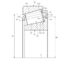
図1は本発明に係る円すいころ軸受を示し、この円すいころ軸受は、内輪51と、外輪52と、内輪51と外輪52との間に転動自在に配された複数の円すいころ53と、円すいころ53を円周所定間隔に保持する保持器54とを備える。
FIG. 1 shows a tapered roller bearing according to the present invention. The tapered roller bearing includes an
内輪51はその外径面に円すい状の軌道面55を有し、軌道面55の大径側に外径側へ突出する鍔部56が形成されている。すなわち、軌道面55は鍔部56から小径端まで形成され、従来の円すいころ軸受の内輪のように小径側に鍔部を有さない。軌道面55と鍔部56との間のコーナ部にはぬすみ部57を形成している。また、図2に示すように、鍔部56の内面(つまり小径側の端面)56bは、軸受軸心Pと直交する平面に対して所定角度αだけ傾斜している。
The
鍔部56はその内面56bにて円すいころ53の大端面53aを受け、円すいころ53を通じてかかるアキシャル荷重を受けて、円すいころ53を回転案内する大鍔である。なお、従来において設けられている小鍔は、軸受回転中には特別な役割を果たすものでなく、このようなものを本発明では省略していることになる。
The
外輪52はその内径面に円すい状の軌道面60を有し、この軌道面60と内輪51の軌道面55とを、保持器54で保持された複数の円すいころ53が転動することになる。
The
この円すいころ軸受では、円すいころ53と内外輪51、52の軌道面55、60とが線接触しており、内・外輪軌道面55、60およびころ中心Oが軸心P上の一点(図示せず)に一致するよう設計される。
In this tapered roller bearing, the tapered
また、保持器54は、図1と図2に示すように、一対の環状部54a、54bと、円周等配位置でころ中心O方向に延びて環状部54a、54bを連結する柱部54cとを備える。そして、周方向に沿って隣合う柱部54c、54cで仕切られたポケット54dに円すいころ53が回転自在に収容される。
As shown in FIGS. 1 and 2, the retainer 54 includes a pair of
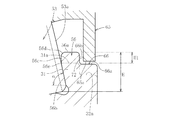
大径側環状部54aは、外端面には、内径方向へ突出する矩形平板状の平板引っ掛け部65が周方向に沿って所定ピッチで複数個が配置されている。この引っ掛け部65が内輪51の鍔部56に係合する。すなわち、図2に示すように、内輪51の鍔部56の外径面56aの大径側に切欠部66を形成し、この切欠部66に前記引っ掛け部65を係合させる。この際、引っ掛け部65と切欠部66との間には軸方向および半径方向に僅かな隙間があり、これより保持器54は軸方向および半径方向に僅かに移動可能である。すなわち、この引っ掛け部65は、運転中(軸受組立状態)において保持器が軸中心に対し中立状態では内輪51の鍔部56に接触せずこの鍔部56に非接触となる場合と、内輪54の鍔部56の底面66aと引っ掛け部65の内面65a(内径面)が接触状態となる場合があり、非運転中では内輪51と円すいころ53と保持器54が組立状態を保てるような引っ掛かりがある。このため、切欠部66の切欠寸法は、引っ掛け部65の内径端65aと切欠部66の底面66aとの許容されるべき相対的接近量と、引っ掛け部65の内面72と切欠部66の径方向切欠面66bとの許容されるべき相互接近量とによって設定される。
The large-diameter-side
内輪51の鍔部56の最大高さ寸法Hを、円すいころ53の大端面53aの直径D(図1参照)の30%以上としている。これは、図4に示す従来品では、鍔部の最大高さ寸法Hは、円すいころ53の大端面53aの直径Dの20%以上30%未満であり、図2に示すように、H1程度、すなわち、切欠部66の径方向端面66aの高さ位置を、従来品の鍔部の最大外径面程度に上げることができる。なお、図2における仮想線は従来品を示している。この場合、鍔部56は、円すいころ53の大端面53aと接触する内径側内面56bと、この内径側内面56bから外径側に円すいころ53の大端面53aから離間するように延びる延長面56cと、外径面56aと、外径面56aと延長面56cとの間のチャンファ56dとを備える。また、内径側内面56bと延長面56cとの境57eよりも前記引っ掛け部の内径面を半径方向外方に位置させている。
The maximum height dimension H of the
ところで、保持器54は、鋼板をプレス加工して製作したものであっても、合成樹脂材を成型したものであってもよい。鋼鈑としては、SPHC等の熱間圧延鋼、SPCC等の冷間圧延鋼、SPB2等の冷間圧延鋼や軸受用みがき帯鋼等を使用することができる。また、合成樹脂材としてはエンジニアリングプラスチック製とするのが好ましい。鉄板製保持器は耐油性(油への浸漬による材質劣化)を気にせず使用できるというメリットがある。また、樹脂製すなわちエンジニアリングプラスチック製とすれば、樹脂製保持器は軸受の組立において底広げ、かしめといった作業が不要となるため、所要の寸法精度を確保することが容易である。また、樹脂製保持器は鉄板製に比べ保持器重量が軽く、自己潤滑性があり、摩擦係数が小さいという特徴があるため、軸受内に介在する潤滑油の効果と相俟って、外輪との接触による摩耗の発生を抑えることが可能になる。また、樹脂製保持器は重量が軽く摩擦係数が小さいため、軸受起動時のトルク損失や保持器摩耗の低減に好適である。なお、エンジニアリングプラスチック(エンプラ)とは、合成樹脂のなかで主に耐熱性が優れており、強度が必要とされる分野に使うことのできるものをいう。さらに耐熱性・強度を増した樹脂をスーパーエンプラと呼び、このスーパーエンプラを使用してもよい。 By the way, the retainer 54 may be manufactured by pressing a steel plate or may be formed by molding a synthetic resin material. As the steel plate, hot rolled steel such as SPHC, cold rolled steel such as SPCC, cold rolled steel such as SPB2, or a rolled steel strip for bearings can be used. The synthetic resin material is preferably made of engineering plastic. An iron plate cage has the merit that it can be used without worrying about oil resistance (material deterioration due to immersion in oil). Further, if the resin cage is made of resin, that is, made of engineering plastic, it is not necessary to perform operations such as bottom expansion and caulking in the assembly of the bearing, so that it is easy to ensure the required dimensional accuracy. In addition, the cage made of resin is lighter than the steel plate, is self-lubricating, and has a small coefficient of friction. Therefore, combined with the effect of the lubricating oil in the bearing, It is possible to suppress the occurrence of wear due to the contact of. Further, since the resin cage is light and has a small coefficient of friction, it is suitable for reducing torque loss and cage wear at the time of starting the bearing. The engineering plastic (engineering plastic) is a synthetic resin that is mainly excellent in heat resistance and can be used in fields where strength is required. Further, a resin having increased heat resistance and strength is called a super engineering plastic, and this super engineering plastic may be used.
エンジニアリングプラスチックには、ポリカーボネート(PC)、ポリアミド6(PA6)、ポリアミド66(PA66)、ポリアセタール(POM)、変性ポリフェニレンエーテル(m−PPE)、ポリブチレンテレフタレート(PBT)、GF強化ポリエチレンテレフタレート(GF−PET)、超高分子量ポリエチレン(UHMW−PE)等がある。また、スーパーエンジニアリングプラスチックには、ポリサルホン(PSF)、ポリエーテルサルホン(PES)、ポリフェニレンサルファイド(PPS)、ポリアリレート(PAR)、ポリアミドイミド(PAI)、ポリエーテルイミド(PEI)、ポリエーテルエーテルケトン(PEEK)、液晶ポリマー(LCP)、熱可塑性ポリイミド(TPI)、ポリベンズイミダゾール(PBI)、ポリメチルベンテン(TPX)、ポリ1,4−シクロヘキサンジメチレンテレフタレート(PCT)、ポリアミド46(PA46)、ポリアミド6T(PA6T)、ポリアミド9T(PA9T)、ポリアミド11,12 (PA11,12)、フッ素樹脂、ポリフタルアミド(PPA)等がある。
Engineering plastics include polycarbonate (PC), polyamide 6 (PA6), polyamide 66 (PA66), polyacetal (POM), modified polyphenylene ether (m-PPE), polybutylene terephthalate (PBT), GF reinforced polyethylene terephthalate (GF- PET) and ultra high molecular weight polyethylene (UHMW-PE). Super engineering plastics include polysulfone (PSF), polyethersulfone (PES), polyphenylene sulfide (PPS), polyarylate (PAR), polyamideimide (PAI), polyetherimide (PEI), and polyetheretherketone. (PEEK), liquid crystal polymer (LCP), thermoplastic polyimide (TPI), polybenzimidazole (PBI), polymethylbenten (TPX),
特に、PPS(ポリフェニレンサルファイド樹脂)が好ましい。PPSとは、フェニル基(ベンゼン環)とイオウ(S)が交互に繰り返される分子構造を持った高性能エンジニアリングプラスチックである。結晶性で,連続使用温度は200℃〜220℃、高荷重(1.82MPa)での荷重たわみ温度が260℃以上と耐熱性に優れ,しかも引っ張り強さや曲げ強さが大きい。成形時の収縮率は0.3〜0.5%と小さいので寸法安定性が良い。難燃性や耐薬品性の点でも優れている。PPSは,架橋型,直鎖型,半架橋型の3種に大別できる。架橋型は低分子量ポリマーを架橋して高分子量化したもので,脆く,ガラス繊維で強化したグレードが中心である。直鎖型は重合段階で架橋工程がなしに高分子量化したもので,靭性が高い。半架橋型は,架橋型と直鎖型の特性を併せ持つ特徴を持っている。 In particular, PPS (polyphenylene sulfide resin) is preferable. PPS is a high-performance engineering plastic having a molecular structure in which phenyl groups (benzene rings) and sulfur (S) are alternately repeated. It is crystalline, has a continuous use temperature of 200 ° C. to 220 ° C., a deflection temperature under a high load (1.82 MPa) of 260 ° C. or more, and is excellent in heat resistance, and has high tensile strength and bending strength. Since the shrinkage rate during molding is as small as 0.3 to 0.5%, the dimensional stability is good. Excellent in flame retardancy and chemical resistance. PPS can be broadly classified into three types: cross-linked, linear, and semi-cross-linked. The cross-linked type is a high molecular weight product obtained by cross-linking a low molecular weight polymer, and is mainly brittle and reinforced with glass fiber. The straight-chain type has a high toughness and has a high molecular weight without a crosslinking step in the polymerization stage. The semi-cross-linked type has the characteristics of both the cross-linked type and the straight chain type.
ところで、この円すいころ軸受では、外輪52の最小内径寸法D1を、内輪51の鍔部56の最大外径寸法D2よりも大きくしている。これは、外輪形成素材と内輪形成素材とを一体とする親子鍛造により、外輪52と内輪51とを成形することができるようにするためである。すなわち、親子鍛造では、図3に示すような、外輪形成部80と内輪形成部81とが一体の筒状素材82を鍛造成形し、その後、外輪形成部80と内輪形成部81を分離し、外輪形成部80から外輪52を成形するとともに、内輪形成部81から内輪51を成形する。
By the way, in this tapered roller bearing, the minimum inner diameter dimension D1 of the
このため、外輪52の最小内径寸法D1が、内輪51の鍔部56の最大外径寸法D2よりも大きく設定しなければ、このような親子鍛造を達成することができないからである。
For this reason, unless the minimum inner diameter dimension D1 of the
次にこの円すいころ軸受の組立方法を説明する。まず、各保持器54のポケット54dに円すいころ53を収容する。その後、この保持器54と円すいころ53との組合体に、内輪51を内嵌する。逆に言えば、保持器54と円すいころ53との組合体を内輪51に外嵌する。この際、引っ掛け部65を内輪51の切欠部66に嵌合させる必要がある。嵌合させるには、樹脂保持器の場合は引っ掛け部65を弾性変形させて嵌合させればよい。鉄板保持器の場合は、引っ掛け部65を内輪鍔部56の最大外径寸法D2より拡げた寸法で製作し、保持器54と円すいころ53との組合体に内輪51を内嵌した後、引っ掛け部65の加締めを行えばよい。
Next, a method for assembling the tapered roller bearing will be described. First, the tapered
その後、内輪51と円すいころ53と保持器54との組合体を一対形成し、各組合体を、外輪52に挿入することによって、内輪51と円すいころ53と保持器54と外輪52とが一体化された円すいころ軸受を組み立てることができる。
Thereafter, a pair of combinations of the
本発明の円すいころ軸受では、内輪51の軌道面55が、鍔部56から小径端に達するものであって、従来において存在していた内輪51の小径側の鍔部およびぬすみ部を省略したものである。このため、この省略する鍔部およびぬすみ部分だけ、軌道面55を大きくとることができる。また、非運転中において保持器54に内輪の鍔部に係合する引っ掛け部65を設けたので、円すいころ53が小端側へ脱落するのを防止できる。
In the tapered roller bearing of the present invention, the
内輪51の鍔部56の最大高さ寸法Hを、円すいころ53の大端面53aの直径の30%以上としたので、内輪51の軌道面55の軸方向長さを短くすることなく、鍔部56の強度を確保できる。すなわち、内輪51の軌道面55は、鍔部56側から反鍔部側に向かって縮径しているので、鍔部56の内面(ころ大端面対応面)56bは、この軌道面55と直交する方向に立ち上がることになり、鍔部56の高さ寸法を大きくすれば、それに対応して、鍔部56は外径側に向かって軸方向長さが大となるからである。
Since the maximum height dimension H of the
引っ掛け部にて、内輪からのころの離脱を安定して防止できる。これによって、組み込み性の向上を図ることできる。また、運転中においては引っ掛け部は回転の妨げにならず、円滑な回転が可能となる。 The hook can stably prevent the roller from separating from the inner ring. As a result, the incorporation can be improved. In addition, during operation, the hooking portion does not hinder rotation, and smooth rotation is possible.
外輪52の最小内径寸法を内輪51の鍔部56の最大外径寸法よりも大きく設定したことによって、外輪52と内輪51との同時鍛造(親子鍛造)が可能となって、材料の歩留まりを高めることができて、生産性に優れたものとなる。
By setting the minimum inner diameter dimension of the
このように、本円すいころ軸受は自走車両の動力伝達軸を支持する軸受に最適となる。 Thus, the tapered roller bearing is optimal for a bearing that supports the power transmission shaft of the self-propelled vehicle.
以上、本発明の実施形態につき説明したが、本発明は前記実施形態に限定されることなく種々の変形が可能であって、例えば、引っ掛け部65の数としては、その増減は任意であるが、安定して円すいころ23の落下を防止する上で、少なくとも1個あればよく、強度および組み込み性を考慮すれば、周方向に沿って定ピッチで4〜8個程度配置するのが好ましい。また、引っ掛け部65をリング部にて構成してもよい。切欠部66として、実施形態では、内輪51の大径側の端面69に開口しているが、この端面69に開口させずに、鍔部56の外径面56aに形成される環状の凹溝にて構成してもよい。
As described above, the embodiment of the present invention has been described. However, the present invention is not limited to the above-described embodiment, and various modifications can be made. For example, the number of the
この円すいころ軸受は、自動車のデファレンシャルやトランスミッションに用いることができる他、従来から円すいころ軸受を用いることができる種々の部位に用いることができる。なお、この円すいころ軸受として、図1に示すように単列で使用しても、一対を突き合わせて複列で使用してもよい。 This tapered roller bearing can be used for a differential or a transmission of an automobile, and can be used for various parts where a tapered roller bearing can be conventionally used. The tapered roller bearing may be used in a single row as shown in FIG. 1 or may be used in a double row by abutting a pair.
51 内輪
52 外輪
54a 大径側環状部
54b 小径側環状部
65 引っ掛け部
66 切欠部
51
Claims (1)
前記保持器は、大径側環状部と、小径側環状部と、大径側環状部と小径側環状部とを連結する柱部とを備え、前記大径側環状部に、引っ掛け部を設け、前記内輪の鍔部の最大高さ寸法を、円すいころの大端面の直径の30%以上とするともに、引っ掛け部は、内径側から円すいころの大端面に対して離間しつつ径方向外方へ延在した矩形平板形状であって、前記鍔部は、円すいころの大端面と接触する内径側内面と、この内径側内面から外径側に円すいころの大端面から離間するように延びる延長面と、外径面と、外径面と延長面との間のチャンファとを備え、かつ、前記引っ掛け部は、内輪と円すいころと保持器が組立状態を保てるような引っ掛かりが内輪の鍔部に対してあり、保持器が軸中心に対し中立状態では鍔部に非接触であり、運転中には鍔部に非接触もしくは、鍔部に接触する場合は、引っ掛け部内面と鍔部の切欠部の底面が接触状態となるように設定するとともに、前記中立状態において、内径側内面と延長面との境よりも前記引っ掛け部の内径面を半径方向外方に位置させ、引っ掛け部は組み立て時には弾性変形が許容されることを特徴とする円すいころ軸受。 The inner ring includes an inner ring, an outer ring, a plurality of tapered rollers arranged to roll between the inner ring and the outer ring, and a retainer that holds the tapered rollers at a predetermined circumferential interval. Rutotomoni provided a flange portion only on the side for guiding the tapered rollers, the minimum inner diameter dimension of the outer ring, is larger than the maximum outer diameter dimension of the inner ring of the flange portion, and the metal cage and the resin cage as the cage A tapered roller bearing that supports a power transmission shaft of a self-propelled vehicle as a PPS in a resin cage ,
The cage includes a large-diameter-side annular portion, a small-diameter-side annular portion, and a column portion that connects the large-diameter-side annular portion and the small-diameter-side annular portion, and a hook portion is provided in the large-diameter-side annular portion. The maximum height dimension of the flange portion of the inner ring is 30% or more of the diameter of the large end surface of the tapered roller, and the hooking portion is radially outward while being spaced from the large end surface of the tapered roller from the inner diameter side. The flange has a rectangular flat plate shape, and the flange portion extends from the inner diameter side inner surface in contact with the large end surface of the tapered roller, and extends from the inner diameter side inner surface to the outer diameter side so as to be separated from the large end surface of the tapered roller. A hook portion between the inner ring, the tapered roller, and the retainer in an assembled state, and a hook portion between the outer ring surface and the extension surface. When the cage is in a neutral state with respect to the shaft center, the When not in contact with the collar part or in contact with the collar part, set the hook part inner surface and the bottom surface of the notch part of the collar part to be in contact with each other, and in the neutral state, extend with the inner diameter side inner surface. A tapered roller bearing, wherein an inner diameter surface of the hook portion is positioned radially outward from a boundary with the surface, and the hook portion is allowed to be elastically deformed when assembled .
Priority Applications (4)
| Application Number | Priority Date | Filing Date | Title |
|---|---|---|---|
| JP2007202084A JP5183998B2 (en) | 2007-08-02 | 2007-08-02 | Tapered roller bearing |
| PCT/JP2008/063674 WO2009017159A1 (en) | 2007-08-02 | 2008-07-30 | Tapered roller bearing |
| US12/670,719 US20100209036A1 (en) | 2007-08-02 | 2008-07-30 | Tapered roller bearing |
| EP08791905.6A EP2182231B1 (en) | 2007-08-02 | 2008-07-30 | Tapered roller bearing |
Applications Claiming Priority (1)
| Application Number | Priority Date | Filing Date | Title |
|---|---|---|---|
| JP2007202084A JP5183998B2 (en) | 2007-08-02 | 2007-08-02 | Tapered roller bearing |
Publications (2)
| Publication Number | Publication Date |
|---|---|
| JP2009036327A JP2009036327A (en) | 2009-02-19 |
| JP5183998B2 true JP5183998B2 (en) | 2013-04-17 |
Family
ID=40304389
Family Applications (1)
| Application Number | Title | Priority Date | Filing Date |
|---|---|---|---|
| JP2007202084A Expired - Fee Related JP5183998B2 (en) | 2007-08-02 | 2007-08-02 | Tapered roller bearing |
Country Status (4)
| Country | Link |
|---|---|
| US (1) | US20100209036A1 (en) |
| EP (1) | EP2182231B1 (en) |
| JP (1) | JP5183998B2 (en) |
| WO (1) | WO2009017159A1 (en) |
Families Citing this family (20)
| Publication number | Priority date | Publication date | Assignee | Title |
|---|---|---|---|---|
| JP2011226495A (en) * | 2010-04-15 | 2011-11-10 | Ntn Corp | Retainer for conical bearing, retainer manufacturing method, and conical bearing |
| DE102011004200A1 (en) * | 2011-02-16 | 2012-08-16 | Schaeffler Technologies Gmbh & Co. Kg | Needle bearing with bordlosem inner ring |
| WO2013162436A1 (en) * | 2012-04-23 | 2013-10-31 | Aktiebolaget Skf | Bearing arrangement |
| JP2015514949A (en) * | 2012-04-23 | 2015-05-21 | アクティエボラゲット・エスコーエッフ | Toroidal roller bearing |
| JP2013238295A (en) * | 2012-05-16 | 2013-11-28 | Jtekt Corp | Rolling bearing |
| DE102012217506B4 (en) * | 2012-09-27 | 2014-07-10 | Schaeffler Technologies Gmbh & Co. Kg | Bearing arrangement for a transmission |
| JP6458459B2 (en) * | 2013-12-25 | 2019-01-30 | 株式会社ジェイテクト | Tapered roller bearing |
| JP6520061B2 (en) | 2013-12-25 | 2019-05-29 | 株式会社ジェイテクト | Ball bearing |
| JP6459396B2 (en) * | 2014-10-29 | 2019-01-30 | 株式会社ジェイテクト | Tapered roller bearing |
| JP6459395B2 (en) * | 2014-10-29 | 2019-01-30 | 株式会社ジェイテクト | Tapered roller bearing |
| JP6565164B2 (en) | 2014-10-29 | 2019-08-28 | 株式会社ジェイテクト | Cage and tapered roller bearing for tapered roller bearing |
| JP6492540B2 (en) | 2014-10-29 | 2019-04-03 | 株式会社ジェイテクト | Tapered roller bearing |
| JP6565163B2 (en) | 2014-10-29 | 2019-08-28 | 株式会社ジェイテクト | Tapered roller bearing |
| JP6458447B2 (en) | 2014-10-29 | 2019-01-30 | 株式会社ジェイテクト | Tapered roller bearing |
| JP6776536B2 (en) * | 2016-01-14 | 2020-10-28 | 株式会社ジェイテクト | Tapered roller bearing |
| JP6694288B2 (en) | 2016-02-05 | 2020-05-13 | ナブテスコ株式会社 | Roller bearing |
| JP6790517B2 (en) | 2016-07-06 | 2020-11-25 | 株式会社ジェイテクト | Tapered roller bearing |
| JP2021004659A (en) * | 2019-06-27 | 2021-01-14 | ナブテスコ株式会社 | Rolling mechanism, reduction gear and method for manufacturing rolling mechanism |
| JP2021179252A (en) | 2020-05-08 | 2021-11-18 | ナブテスコ株式会社 | Inner race of bearing, rotary machine, and speed reducer |
| JP2023103773A (en) * | 2022-01-14 | 2023-07-27 | 日本精工株式会社 | tapered roller bearing |
Family Cites Families (43)
| Publication number | Priority date | Publication date | Assignee | Title |
|---|---|---|---|---|
| US956588A (en) * | 1910-05-03 | Hyatt Roller Bearing Co | Combined roll and ball bearing. | |
| US991218A (en) * | 1910-04-28 | 1911-05-02 | Hyatt Roller Bearing Co | Roller-bearing with resilient cage. |
| US1057861A (en) * | 1912-09-06 | 1913-04-01 | Hyatt Roller Bearing Co | Casing-lock for roller-bearings. |
| US1093795A (en) * | 1913-08-16 | 1914-04-21 | Onesime E Michaud | Roller-bearing. |
| US1231752A (en) * | 1914-03-07 | 1917-07-03 | Arthur M Laycock | Ball-bearing. |
| US1188712A (en) * | 1915-06-04 | 1916-06-27 | George Avrunin | Bearing. |
| US1230145A (en) * | 1917-04-06 | 1917-06-19 | Edward S Folk | Roller-bearing. |
| US1349307A (en) * | 1917-10-22 | 1920-08-10 | Chicago Bearings Company | Roller-bearing |
| US1795471A (en) * | 1929-04-03 | 1931-03-10 | Timken Roller Bearing Co | Self-aligning bearing |
| US1862641A (en) * | 1930-08-01 | 1932-06-14 | Timken Roller Bearing Co | Roller bearing |
| US1909617A (en) * | 1930-08-01 | 1933-05-16 | Timken Roller Bearing Co | Roller bearing and cage |
| US1941460A (en) * | 1932-11-14 | 1934-01-02 | Timken Roller Bearing Co | Double row roller bearing |
| US2218985A (en) * | 1938-09-09 | 1940-10-22 | Gen Motors Corp | Roller bearing |
| US2435839A (en) * | 1945-12-24 | 1948-02-10 | Timken Roller Bearing Co | Taper roller bearing and cage |
| US2897581A (en) * | 1955-08-26 | 1959-08-04 | Torrington Co | Method of making roller bearings |
| US3004809A (en) * | 1957-12-19 | 1961-10-17 | Skf Svenska Kullagerfab Ab | Thrust roller bearings |
| US3028658A (en) * | 1959-08-17 | 1962-04-10 | Federal Mogul Bower Bearings | Retainer ring and roller bearing assembly and method and machine for assembling roller bearings |
| SE338907B (en) * | 1970-05-08 | 1971-09-20 | Skfind Handel En Ontwikkeling | |
| DE2219327B2 (en) * | 1972-04-20 | 1974-08-29 | Daimler-Benz Ag, 7000 Stuttgart | Tapered roller bearings for wheel bearings in motor vehicles |
| US4601592A (en) * | 1982-03-17 | 1986-07-22 | The Timken Company | Tapered roller bearing capable of sustained operation without lubricant replenishment |
| JPS58165324A (en) | 1982-03-25 | 1983-09-30 | Nec Corp | Measurement of integrated exposure of mask aliner |
| US4523862A (en) * | 1983-06-07 | 1985-06-18 | Koyo Seiko Company Limited | Tapered roller bearing |
| JPS607423U (en) * | 1983-06-28 | 1985-01-19 | 光洋精工株式会社 | tapered roller bearing |
| DE3527033A1 (en) * | 1985-07-27 | 1987-02-05 | Skf Gmbh | RADIAL ROLLER BEARING |
| US5009523A (en) * | 1989-07-20 | 1991-04-23 | The Timken Company | Double row bearing assembly |
| JP2871752B2 (en) * | 1989-10-27 | 1999-03-17 | 三井化学株式会社 | Cage for rolling bearing |
| US5236264A (en) * | 1991-06-10 | 1993-08-17 | Nsk Ltd. | Linear bearing |
| US5401105A (en) * | 1992-12-28 | 1995-03-28 | Nsk Ltd. | Ball bearing and method for producing a cage of the ball bearing |
| JP3011093B2 (en) * | 1996-04-05 | 2000-02-21 | 日本精工株式会社 | Tapered roller bearings for automobiles |
| JP3699249B2 (en) * | 1997-07-28 | 2005-09-28 | Ntn株式会社 | Hub unit bearing and manufacturing method thereof |
| JPH11236920A (en) * | 1998-02-24 | 1999-08-31 | Nippon Seiko Kk | Rolling bearing |
| US6328477B1 (en) * | 1998-11-27 | 2001-12-11 | Ntn Corporation | Tapered roller bearings and gear shaft support devices |
| JP2002054638A (en) * | 2000-08-07 | 2002-02-20 | Ntn Corp | Tapered roller bearing |
| US6547443B2 (en) * | 2000-10-17 | 2003-04-15 | Ntn Corporation | Tapered roller bearing |
| JP2005016656A (en) * | 2003-06-27 | 2005-01-20 | Ntn Corp | Tapered roller bearing |
| JP2005098412A (en) * | 2003-09-25 | 2005-04-14 | Koyo Seiko Co Ltd | Tapered roller bearing |
| JP2005265126A (en) * | 2004-03-19 | 2005-09-29 | Ntn Corp | Full roller type tapered roller bearing |
| JP2005273796A (en) * | 2004-03-25 | 2005-10-06 | Koyo Seiko Co Ltd | Bearing device for supporting pinion shaft |
| EP1746297B1 (en) * | 2004-04-14 | 2018-11-14 | Jtekt Corporation | Tapered roller bearing, tapered roller bearing assembly, and pinion shaft supporting device with the tapered roller bearing assembly for a vehicle |
| DE102004018188A1 (en) * | 2004-04-14 | 2005-11-10 | Fag Kugelfischer Ag & Co. Ohg | Double row angular contact bearing |
| JP2006022935A (en) * | 2004-07-05 | 2006-01-26 | Ntn Corp | Tapered roller bearing |
| DE602006018399D1 (en) * | 2005-08-25 | 2011-01-05 | Ntn Toyo Bearing Co Ltd | Tapered roller bearings |
| JP2008304003A (en) * | 2007-06-08 | 2008-12-18 | Ntn Corp | Tapered roller bearing |
-
2007
- 2007-08-02 JP JP2007202084A patent/JP5183998B2/en not_active Expired - Fee Related
-
2008
- 2008-07-30 EP EP08791905.6A patent/EP2182231B1/en not_active Not-in-force
- 2008-07-30 US US12/670,719 patent/US20100209036A1/en not_active Abandoned
- 2008-07-30 WO PCT/JP2008/063674 patent/WO2009017159A1/en active Application Filing
Also Published As
| Publication number | Publication date |
|---|---|
| JP2009036327A (en) | 2009-02-19 |
| WO2009017159A1 (en) | 2009-02-05 |
| EP2182231A4 (en) | 2012-01-11 |
| EP2182231B1 (en) | 2014-03-12 |
| US20100209036A1 (en) | 2010-08-19 |
| EP2182231A1 (en) | 2010-05-05 |
Similar Documents
| Publication | Publication Date | Title |
|---|---|---|
| JP5183998B2 (en) | Tapered roller bearing | |
| WO2008056562A1 (en) | Tapered roller bearing | |
| JP6047999B2 (en) | Rotating support device | |
| JP2008304003A (en) | Tapered roller bearing | |
| JP2009250412A (en) | Cylindrical roller bearing | |
| JP4722822B2 (en) | Tandem type double row angular contact ball bearing | |
| US8123414B2 (en) | Tapered roller bearing | |
| JP6324692B2 (en) | Tapered roller bearing | |
| WO2003058083A1 (en) | Roller bearing | |
| JP2008281139A (en) | Conical roller bearing | |
| JP5128112B2 (en) | Tapered roller bearing | |
| JP5602803B2 (en) | Tapered roller bearing | |
| JP2015010715A (en) | Cage for bearing, in particular for bearing of electrical steering system of motor vehicle | |
| JP4964696B2 (en) | Double row tapered roller bearing | |
| JP5982753B2 (en) | Tapered roller bearing assembly method | |
| JP5289796B2 (en) | Tapered roller bearing retainer manufacturing method and tapered roller bearing | |
| JP5553958B2 (en) | Tapered roller bearing | |
| JP4912950B2 (en) | Tapered roller bearing | |
| JP5476593B2 (en) | Shell needle bearing | |
| JP6137348B2 (en) | Tapered roller bearing | |
| JP2008281036A (en) | Conical roller bearing and its manufacturing method | |
| JP2008196544A (en) | Conical roller bearing | |
| WO2021235022A1 (en) | Self-aligning roller bearing retainer | |
| JP2009052578A (en) | Conical roller bearing | |
| JP4563884B2 (en) | Needle roller bearing |
Legal Events
| Date | Code | Title | Description |
|---|---|---|---|
| RD04 | Notification of resignation of power of attorney |
Free format text: JAPANESE INTERMEDIATE CODE: A7424 Effective date: 20091104 |
|
| A621 | Written request for application examination |
Free format text: JAPANESE INTERMEDIATE CODE: A621 Effective date: 20100705 |
|
| A131 | Notification of reasons for refusal |
Free format text: JAPANESE INTERMEDIATE CODE: A131 Effective date: 20120926 |
|
| A521 | Request for written amendment filed |
Free format text: JAPANESE INTERMEDIATE CODE: A523 Effective date: 20121116 |
|
| TRDD | Decision of grant or rejection written | ||
| A01 | Written decision to grant a patent or to grant a registration (utility model) |
Free format text: JAPANESE INTERMEDIATE CODE: A01 Effective date: 20121226 |
|
| A61 | First payment of annual fees (during grant procedure) |
Free format text: JAPANESE INTERMEDIATE CODE: A61 Effective date: 20130116 |
|
| R150 | Certificate of patent or registration of utility model |
Ref document number: 5183998 Country of ref document: JP Free format text: JAPANESE INTERMEDIATE CODE: R150 Free format text: JAPANESE INTERMEDIATE CODE: R150 |
|
| FPAY | Renewal fee payment (event date is renewal date of database) |
Free format text: PAYMENT UNTIL: 20160125 Year of fee payment: 3 |
|
| R250 | Receipt of annual fees |
Free format text: JAPANESE INTERMEDIATE CODE: R250 |
|
| R250 | Receipt of annual fees |
Free format text: JAPANESE INTERMEDIATE CODE: R250 |
|
| R250 | Receipt of annual fees |
Free format text: JAPANESE INTERMEDIATE CODE: R250 |
|
| R250 | Receipt of annual fees |
Free format text: JAPANESE INTERMEDIATE CODE: R250 |
|
| R250 | Receipt of annual fees |
Free format text: JAPANESE INTERMEDIATE CODE: R250 |
|
| LAPS | Cancellation because of no payment of annual fees |