JP2008281036A - Conical roller bearing and its manufacturing method - Google Patents
Conical roller bearing and its manufacturing method Download PDFInfo
- Publication number
- JP2008281036A JP2008281036A JP2007123651A JP2007123651A JP2008281036A JP 2008281036 A JP2008281036 A JP 2008281036A JP 2007123651 A JP2007123651 A JP 2007123651A JP 2007123651 A JP2007123651 A JP 2007123651A JP 2008281036 A JP2008281036 A JP 2008281036A
- Authority
- JP
- Japan
- Prior art keywords
- tapered roller
- roller bearing
- ring
- hook member
- inner ring
- Prior art date
- Legal status (The legal status is an assumption and is not a legal conclusion. Google has not performed a legal analysis and makes no representation as to the accuracy of the status listed.)
- Withdrawn
Links
- 238000004519 manufacturing process Methods 0.000 title claims abstract description 14
- 229920005989 resin Polymers 0.000 claims abstract description 14
- 239000011347 resin Substances 0.000 claims abstract description 14
- 230000002093 peripheral effect Effects 0.000 claims description 32
- 239000002184 metal Substances 0.000 claims description 9
- 229910052751 metal Inorganic materials 0.000 claims description 9
- 239000004734 Polyphenylene sulfide Substances 0.000 description 8
- 239000000463 material Substances 0.000 description 8
- 229920000069 polyphenylene sulfide Polymers 0.000 description 8
- 230000005540 biological transmission Effects 0.000 description 5
- 238000004080 punching Methods 0.000 description 5
- XEEYBQQBJWHFJM-UHFFFAOYSA-N Iron Chemical compound [Fe] XEEYBQQBJWHFJM-UHFFFAOYSA-N 0.000 description 4
- 238000000465 moulding Methods 0.000 description 4
- 238000010348 incorporation Methods 0.000 description 3
- 238000000034 method Methods 0.000 description 3
- 239000002699 waste material Substances 0.000 description 3
- 229910000831 Steel Inorganic materials 0.000 description 2
- 239000010960 cold rolled steel Substances 0.000 description 2
- 229920006351 engineering plastic Polymers 0.000 description 2
- 229910052742 iron Inorganic materials 0.000 description 2
- 238000002844 melting Methods 0.000 description 2
- 230000008018 melting Effects 0.000 description 2
- 229920000642 polymer Polymers 0.000 description 2
- 239000010959 steel Substances 0.000 description 2
- 229920003002 synthetic resin Polymers 0.000 description 2
- 239000000057 synthetic resin Substances 0.000 description 2
- 229920005992 thermoplastic resin Polymers 0.000 description 2
- 239000013585 weight reducing agent Substances 0.000 description 2
- 101100304647 Saccharomyces cerevisiae (strain ATCC 204508 / S288c) RPL39 gene Proteins 0.000 description 1
- 230000004323 axial length Effects 0.000 description 1
- 230000003247 decreasing effect Effects 0.000 description 1
- 239000000446 fuel Substances 0.000 description 1
- 230000006872 improvement Effects 0.000 description 1
- 238000012986 modification Methods 0.000 description 1
- 230000004048 modification Effects 0.000 description 1
- 238000003825 pressing Methods 0.000 description 1
- 230000009467 reduction Effects 0.000 description 1
Images




Classifications
-
- F—MECHANICAL ENGINEERING; LIGHTING; HEATING; WEAPONS; BLASTING
- F16—ENGINEERING ELEMENTS AND UNITS; GENERAL MEASURES FOR PRODUCING AND MAINTAINING EFFECTIVE FUNCTIONING OF MACHINES OR INSTALLATIONS; THERMAL INSULATION IN GENERAL
- F16C—SHAFTS; FLEXIBLE SHAFTS; ELEMENTS OR CRANKSHAFT MECHANISMS; ROTARY BODIES OTHER THAN GEARING ELEMENTS; BEARINGS
- F16C19/00—Bearings with rolling contact, for exclusively rotary movement
- F16C19/22—Bearings with rolling contact, for exclusively rotary movement with bearing rollers essentially of the same size in one or more circular rows, e.g. needle bearings
- F16C19/34—Bearings with rolling contact, for exclusively rotary movement with bearing rollers essentially of the same size in one or more circular rows, e.g. needle bearings for both radial and axial load
- F16C19/36—Bearings with rolling contact, for exclusively rotary movement with bearing rollers essentially of the same size in one or more circular rows, e.g. needle bearings for both radial and axial load with a single row of rollers
- F16C19/364—Bearings with rolling contact, for exclusively rotary movement with bearing rollers essentially of the same size in one or more circular rows, e.g. needle bearings for both radial and axial load with a single row of rollers with tapered rollers, i.e. rollers having essentially the shape of a truncated cone
-
- F—MECHANICAL ENGINEERING; LIGHTING; HEATING; WEAPONS; BLASTING
- F16—ENGINEERING ELEMENTS AND UNITS; GENERAL MEASURES FOR PRODUCING AND MAINTAINING EFFECTIVE FUNCTIONING OF MACHINES OR INSTALLATIONS; THERMAL INSULATION IN GENERAL
- F16C—SHAFTS; FLEXIBLE SHAFTS; ELEMENTS OR CRANKSHAFT MECHANISMS; ROTARY BODIES OTHER THAN GEARING ELEMENTS; BEARINGS
- F16C33/00—Parts of bearings; Special methods for making bearings or parts thereof
- F16C33/30—Parts of ball or roller bearings
- F16C33/46—Cages for rollers or needles
- F16C33/4617—Massive or moulded cages having cage pockets surrounding the rollers, e.g. machined window cages
- F16C33/4623—Massive or moulded cages having cage pockets surrounding the rollers, e.g. machined window cages formed as one-piece cages, i.e. monoblock cages
- F16C33/4635—Massive or moulded cages having cage pockets surrounding the rollers, e.g. machined window cages formed as one-piece cages, i.e. monoblock cages made from plastic, e.g. injection moulded window cages
Landscapes
- Engineering & Computer Science (AREA)
- General Engineering & Computer Science (AREA)
- Mechanical Engineering (AREA)
- Rolling Contact Bearings (AREA)
Abstract
Description
本発明は、円すいころ軸受及びその製造方法に関するものである。 The present invention relates to a tapered roller bearing and a manufacturing method thereof.
自動車におけるエンジンの駆動力は、トランスミッション、プロペラシャフト、デファレンシャル、ドライブシャフトの何れか又は全てを含む動力伝達系を介して車輪に伝達される。 The driving force of the engine in the automobile is transmitted to the wheels via a power transmission system including any or all of a transmission, a propeller shaft, a differential, and a drive shaft.
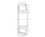
この動力伝達系では、シャフトを支持する軸受として、ラジアル荷重に対する負荷能力が高く、耐衝撃性にも優れる円すいころ軸受を使用する場合が多い。円すいころ軸受は、一般的には、図5に示すように、外周側に円すい状の軌道面1を有する内輪2と、内周側に円すい状の軌道面3を有する外輪4と、内輪2と外輪4との間に転動自在に配された複数の円すいころ5と、円すいころ5を円周所定間隔に保持する保持器6とを備える。
In this power transmission system, a tapered roller bearing having a high load capacity against a radial load and excellent in impact resistance is often used as a bearing for supporting the shaft. As shown in FIG. 5, the tapered roller bearing generally has an
保持器6は、図6に示すように、一対の環状部6a、6bと、環状部6a、6bを相互に連結する柱部6cとを備え、周方向に沿って隣合う柱部6c間に形成されるポケット6dに前記円すいころ5が収容される。
As shown in FIG. 6, the
この円すいころ軸受では、円すいころ5と内外輪2,4の軌道面1、3とが線接触しており、内・外輪軌道面1、3およびころ中心線Oの延長線が軸心P(図5参照)上の一点(図示せず)に一致するよう設計される。
In this tapered roller bearing, the
このため、荷重が作用すると、円すいころ5がその大端側に押圧される。この荷重を受けるべく、内輪2の大径側には外径側へ突出する鍔部7が設けられている。また、この軸受を機械等に組込むまでの間に円すいころ5が小端側へ脱落しないようにするために、内輪2の小端側にも突出する鍔部8が設けられる。
For this reason, when a load acts, the
近年、車内空間の拡大化に伴いエンジンルームの縮小化、エンジンの高出力化、燃費向上のためのトランスミッションの多段化などが進む中、そこに使用される円錐ころ軸受の使用環境は年々厳しくなってきている。このような厳しい使用環境の中では、軸受のさらなる長寿命化が求められる。 In recent years, with the expansion of the interior space of vehicles, the engine room has been reduced, the engine output has been increased, and the transmission has been increased in stages to improve fuel efficiency. It is coming. In such a severe use environment, it is required to further extend the life of the bearing.
軸受の長寿命化の方策として、ころ本数を増やすかころ長さを長くすることによって、同一寸法で負荷容量を現状よりも上げることが考えられる。しかしながら、現在の軸受構造では、前記したように、内輪2の小径側に鍔部(小鍔)8を設けているので、円すいころ5の長さ寸法を大きくするのに限界がある。また、ころ本数を増加することに対しても強度上の理由から、柱部6cの本数と幅の制約がある。このため、従来の軸受構造では負荷容量を上げるのに限界があった。
As a measure for extending the service life of the bearing, it is conceivable to increase the load capacity with the same dimensions from the current state by increasing the number of rollers or increasing the roller length. However, in the current bearing structure, as described above, since the flange portion (small rod) 8 is provided on the small diameter side of the
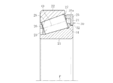
一方、従来の円すいころ軸受の中には、内輪において小径側の鍔部(小鍔)を省略したものがある(特許文献1)。内輪において小径側の鍔部を省略すれば、その省略した分だけ円すいころの軸方向長さを大きくとることができ、負荷容量の増加を図ることができる。この型式の軸受では、図7や図8に示すように、円すいころの組立中に、円すいころが脱落しないように、大径側の鍔部31に係合する引っ掛け部30を保持器24に設けている。この引っ掛け部30は、扁平な矩形片からなり、円周方向等間隔に複数設けられる。なお、図7において、21は内輪、22は外輪、23は円すいころ、24は保持器、25は、大径側環状部、26は小径側環状部、27は柱部である。
On the other hand, in some conventional tapered roller bearings, a small diameter side flange (small flange) is omitted from the inner ring (Patent Document 1). If the collar portion on the small diameter side in the inner ring is omitted, the length of the tapered roller in the axial direction can be increased by that amount, and the load capacity can be increased. In this type of bearing, as shown in FIGS. 7 and 8, the
引っ掛け部30と切欠部32との間には軸方向および半径方向に僅かな隙間があり、これより保持器24は軸方向および半径方向に僅かに移動可能である。すなわち、運転中においては保持器24が内輪21の鍔部31に非接触状態となり非運転中においては保持器24が鍔部31に引っ掛かる。
ところで、引っ掛け部30を設けた保持器24は、形状が複雑であり、樹脂保持器の場合では、成形しにくく、成形金型によって引っ掛け部30の大きさ、位置等が制限される。このため、引っ掛け部30として機能する保持器24の一体成形が困難であった。また、金属製保持器でも、同様に成形性に劣るとともに、引っ掛け部30の成形のための打ち抜きによる材料の無駄等が生じていた。
By the way, the
また、図7に示す円すいころ軸受の組立ては、次に記載する方法で行われる。まず、各保持器24のポケット28に円すいころ23を収納する。その後、この保持器24と円すいころ23の組合体に、内輪21を内嵌する。換言すると、保持器24と円すいころ23との組合体を内輪21に外嵌する。このため、図7のように引っ掛け部30を設けたものでは、保持器24に円すいころ23を並べる際、引っ掛け部30が邪魔となって、従来機での組立性が悪くなるという課題がある。
Further, the tapered roller bearing shown in FIG. 7 is assembled by the method described below. First, the
本発明は、上記課題に鑑みて、引っ掛け部として機能するものを確実に成形でき、また円すいころの組込性の向上を図ることができ、しかも、ころ軸方向長さの延長が可能となって、定格荷重のアップを図ることができる円すいころ軸受及びその製造方法を提供する。 In view of the above-mentioned problems, the present invention can reliably mold what functions as a hook portion, can improve the assemblability of a tapered roller, and can extend the axial length of the roller. Thus, a tapered roller bearing capable of increasing the rated load and a method for manufacturing the same are provided.
本発明の円すいころ軸受は、内輪と、外輪と、内輪と外輪との間に転動自在に配された複数の円すいころと、円すいころを円周所定間隔に保持する保持器とを備え、内輪の外径面の大径側にのみ前記円すいころを案内する鍔部を設けた円すいころ軸受であって、前記保持器は、大径側環状部と、小径側環状部と、大径側環状部と小径側環状部とを連結する柱部とからなる樹脂製の保持器本体と、前記内輪の鍔部に係合する引っ掛け部材とを備え、保持器本体の大径側環状部に周方向溝を設けるとともに、周方向溝に嵌合されるはめ込み部を引っ掛け部材に設けたものである。 The tapered roller bearing of the present invention includes an inner ring, an outer ring, a plurality of tapered rollers arranged to roll between the inner ring and the outer ring, and a cage that holds the tapered rollers at a predetermined circumferential interval. A tapered roller bearing provided with a flange for guiding the tapered roller only on the large diameter side of the outer diameter surface of the inner ring, wherein the cage includes a large diameter annular portion, a small diameter annular portion, and a large diameter side. A retainer body made of resin composed of a pillar portion connecting the annular portion and the small-diameter-side annular portion; and a hook member that engages with the flange portion of the inner ring, and is arranged around the large-diameter-side annular portion of the retainer body. A directional groove is provided, and a fitting portion fitted into the circumferential groove is provided on the hook member.
本発明の円すいころ軸受によれば、従来において存在していた内輪の小径側の鍔部およびぬすみ部を省略したものである。このため、この省略する鍔部およびぬすみ部分だけ、軌道面を大きくとることができる。また、保持器に内輪の鍔部に係合する引っ掛け部材を設けたので、円すいころが小端側へ脱落するのを防止できる。 According to the tapered roller bearing of the present invention, the flange portion and the fillet portion on the small diameter side of the inner ring that existed in the prior art are omitted. For this reason, the raceway surface can be made large only in this omitted collar portion and fillet portion. In addition, since the hook is provided on the cage to engage with the flange portion of the inner ring, it is possible to prevent the tapered roller from falling off to the small end side.
また、保持器本体と引っ掛け部材とを別に成形することができる。これによって、種々の大きさの引っ掛け部を成形することができ、引っ掛け部の位置としても周方向に任意の位置に設けることができる。 Further, the cage body and the hook member can be formed separately. As a result, hooks of various sizes can be formed, and the positions of the hooks can be provided at arbitrary positions in the circumferential direction.
前記引っ掛け部材は、リング部と、このリング部から内径方向へ突出する突出片とからなり、前記はめ込み部がリング部の外周縁部で構成されるとともに、この外周縁部が保持器本体の大径側環状部に設けられた周方向溝に嵌合するものである。このため、周方向の位置あわせを行うことなく、リング部の外周縁部であるはめ込み部を周方向溝に嵌合させることができる。 The hook member includes a ring portion and a protruding piece protruding from the ring portion in the inner diameter direction. The fitting portion is formed by an outer peripheral edge portion of the ring portion, and the outer peripheral edge portion is a large portion of the cage body. It fits into a circumferential groove provided in the radial side annular portion. For this reason, the fitting part which is an outer peripheral part of a ring part can be fitted to a circumferential groove | channel, without performing alignment of the circumferential direction.
前記引っ掛け部材はリング体からなり、前記はめ込み部がリング体の外周縁部で構成されるとともに、この外周縁部が保持器本体の大径側環状部の内径面に設けられた周方向溝に嵌合するものである。この場合も、周方向の位置合わせを行うことなく、リング体の外周縁部であるはめ込み部を周方向溝に嵌合させることができる。 The hook member comprises a ring body, and the fitting portion is constituted by an outer peripheral edge portion of the ring body, and the outer peripheral edge portion is formed in a circumferential groove provided on an inner diameter surface of the large-diameter side annular portion of the cage body. To be fitted. Also in this case, the fitting portion which is the outer peripheral edge portion of the ring body can be fitted into the circumferential groove without performing alignment in the circumferential direction.
前記周方向溝は、底壁と、軸方向内方側の内側周壁と、軸方向外方側の外側周壁とから構成できる。また、周方向溝としては、底壁と、軸方向内方側の内側周壁とから構成して、底壁の反内側周方向壁側の端縁部に、前記外周縁部が係合する突隆部を設けたものであってもよい。 The circumferential groove can be composed of a bottom wall, an inner peripheral wall on the inner side in the axial direction, and an outer peripheral wall on the outer side in the axial direction. Further, the circumferential groove is composed of a bottom wall and an inner circumferential wall on the inner side in the axial direction, and the outer peripheral edge engages with an end edge on the side opposite to the inner circumferential wall of the bottom wall. A ridge may be provided.
引っ掛け部材が矩形平板体からなり、この矩形平板体が前記保持器本体に設けられた嵌合部に嵌合するものとすることができる。これにより、引っ掛け部材を構成するための材料を少なくすることができる。 The hook member may be formed of a rectangular flat plate, and the rectangular flat plate may be fitted into a fitting portion provided in the retainer body. Thereby, the material for comprising a hook member can be decreased.
前記引っ掛け部材を金属製としたり、樹脂製としたりすることができる。特に、樹脂製とした場合、用いる樹脂をPPSとすることができる。PPS(ポリフェニレンスルフィド)は、約280℃の融点を有する結晶性ポリマーで極めて高い耐熱性、強度、剛性、優れた寸法安定性が得られ、同時に熱可塑性樹脂としての優れた成形加工性を備えた耐熱エンジニアリングプラスチックである。 The hook member can be made of metal or resin. In particular, when the resin is used, the resin used can be PPS. PPS (polyphenylene sulfide) is a crystalline polymer having a melting point of about 280 ° C., which has extremely high heat resistance, strength, rigidity, and excellent dimensional stability, and at the same time has excellent molding processability as a thermoplastic resin. Heat resistant engineering plastic.
本発明の円すいころ軸受の製造方法では、内輪と、外輪と、内輪と外輪との間に転動自在に配された複数の円すいころと、円すいころを円周所定間隔に保持する保持器とを備え、内輪の外径面の大径側にのみ前記円すいころを案内する鍔部を設けた円すいころ軸受の製造方法であって、円すいころを収納するポケットを有し、かつ大径側に周方向溝を有する保持器本体と、内輪の鍔部の外側面に係合する引っ掛け部材とを別々に形成した後、内輪の鍔部の外側面に係合する引っ掛け部材を前記周方向溝に嵌合するものである。 In the method of manufacturing a tapered roller bearing according to the present invention, an inner ring, an outer ring, a plurality of tapered rollers arranged to roll between the inner ring and the outer ring, and a cage that holds the tapered rollers at a predetermined circumferential interval. A tapered roller bearing having a flange that guides the tapered roller only on the large diameter side of the outer diameter surface of the inner ring, having a pocket for storing the tapered roller, and on the large diameter side. A cage body having a circumferential groove and a hook member that engages with the outer surface of the inner ring flange are formed separately, and then the hook member that engages with the outer surface of the inner ring flange is formed in the circumferential groove. To be fitted.
内輪の鍔部の外側面に係合する引っ掛け部材を保持器本体に嵌合する前に、保持器本体のポケットに円すいころを収納することができる。 The tapered roller can be stored in the pocket of the cage main body before the hook member that engages with the outer surface of the collar portion of the inner ring is fitted to the cage main body.
本発明の円すいころ軸受の製造方法によれば、軸受組立の際、まず、保持器本体に円すいころを収納した後、引っ掛け部材を保持器本体に大径側から嵌合させることができるため、円すいころを保持器本体に収納する際、引っ掛け部材が邪魔になることがない。しかも、引っ掛け部材を保持器本体に大径側外方から嵌合させることができるので、円すいころの収納作業後には、引っ掛け部材を保持器本体に組付けることができる。なお、引っ掛け部材のはめ込み部を保持器本体の周方向溝に嵌合した後、ころを保持器本体のポケットに収納してもよい。 According to the tapered roller bearing manufacturing method of the present invention, when the bearing is assembled, after the tapered roller is first stored in the cage body, the hook member can be fitted to the cage body from the large diameter side. When the tapered roller is stored in the cage body, the hook member does not get in the way. In addition, since the hook member can be fitted to the cage main body from the outside on the large diameter side, the hook member can be assembled to the cage main body after the tapered roller is stored. In addition, after fitting the fitting part of a hooking member into the circumferential groove | channel of a holder main body, you may accommodate a roller in the pocket of a holder main body.
本発明の円すいころ軸受は、従来において存在していた内輪の小径側の鍔部を省略したものである。このため、この省略する鍔部分の軽量化を図ることができる。さらに、省略した小径側の鍔部及びぬすみ部分だけ、軌道面が大きくなり、これによって円すいころの軸心長さを長くでき、負荷容量を向上させることができて、長寿命化を達成することができる。 In the tapered roller bearing of the present invention, the flange portion on the small diameter side of the inner ring, which has existed in the past, is omitted. For this reason, it is possible to reduce the weight of the omitted flange portion. Furthermore, the raceway surface is enlarged only in the omitted small-diameter side flange and fillet portion, thereby the axial center length of the tapered roller can be increased, the load capacity can be improved, and a longer life can be achieved. Can do.
特に、保持器本体と引っ掛け部材とを別に成形することができて、種々の大きさの引っ掛け部材を成形することができ、引っ掛け部材の位置としても周方向に任意の位置に設けることができる。このため、引っ掛け部材として機能する保持器を確実に成形することができる。しかも、任意の位置に引っ掛け部材を設けることができ、油の循環性向上や強度向上を図ったりすることができる。 In particular, the cage body and the hook member can be formed separately, hook members of various sizes can be formed, and the position of the hook member can be provided at any position in the circumferential direction. For this reason, the cage functioning as a hooking member can be reliably molded. In addition, the hook member can be provided at an arbitrary position, and the oil circulation property and strength can be improved.
前記はめ込み部がリング部やリング体の外周縁部で構成されるとともに、この外周縁部が保持器本体の大径側環状部に設けられた周方向溝に嵌合するものである。このため、引っ掛け部材を容易に保持器本体に接合することができて組込性の向上を図ることができ、しかも、引っ掛け部材のはめ込み部を周方向溝に嵌合させる際、位置合わせが不要となって、一層組込性の向上を図ることができる。 The fitting portion is configured by a ring portion or an outer peripheral edge portion of the ring body, and the outer peripheral edge portion is fitted into a circumferential groove provided in the large-diameter side annular portion of the cage body. For this reason, it is possible to easily join the hook member to the cage body and improve the assemblability, and no alignment is required when fitting the fitting portion of the hook member into the circumferential groove. Thus, it is possible to further improve the incorporation property.
前記周方向溝を、底壁と、軸方向内方側の内側周壁と、軸方向外方側の外側周壁とから構成した場合、はめ込み部の嵌合状態、及び内輪の鍔部への係合状態が安定して、外輪への組立性の向上を図ることができる。また、底壁の反内側周方向壁側の端縁部に、前記外周縁部が係合する突隆部を設けたものでは、引っ掛け部材の保持器本体へのはめ込み力が小さくて済み、引っ掛け部材の組み込み性の向上を図ることができる。 When the circumferential groove is composed of a bottom wall, an inner circumferential wall on the inner side in the axial direction, and an outer peripheral wall on the outer side in the axial direction, the fitting state of the fitting portion and the engagement with the flange portion of the inner ring The state is stable and the assemblability to the outer ring can be improved. In addition, in the case where the protruding portion that engages with the outer peripheral edge portion is provided at the end edge of the bottom wall on the side opposite to the inner circumferential wall, the engaging force of the hooking member to the cage body is small, and the hook is hooked. It is possible to improve the assemblability of the member.
引っ掛け部材が矩形平板体であれば、引っ掛け部材を構成するための材料を少なくすることができ、軽量化を図るとともに、コスト低減に寄与する。 If the hook member is a rectangular flat plate, the material for forming the hook member can be reduced, which contributes to weight reduction and cost reduction.
前記引っ掛け部材を金属製とすることができる。これにより、引っ掛け部材の強度が大となる。さらに、引っ掛け部材が矩形平板体である場合に、保持器の製造工程により生じるブランク(鉄板を打抜いた屑)を引っ掛け部材に利用することができる。このため、歩留まりの向上を図ることができるとともに、製造コストの低減を図ることができる。しかも、保持器本体の形状も複雑なものではないので、成形性に優れるとともに、打ち抜きによる材料の無駄を無くすことができる。 The hook member can be made of metal. Thereby, the intensity | strength of a hook member becomes large. Furthermore, when the hook member is a rectangular flat plate, a blank (debris obtained by punching an iron plate) generated by the manufacturing process of the cage can be used as the hook member. For this reason, the yield can be improved and the manufacturing cost can be reduced. In addition, since the shape of the cage body is not complicated, it is excellent in moldability and waste of material due to punching can be eliminated.
また、前記引っ掛け部材を樹脂製とすることができる。樹脂製保持器は金属製に比べ保持器重量が軽く、自己潤滑性があり、摩擦係数が小さいという特徴があるため、軸受内に介在する潤滑油の効果と相俟って、保持器の摩耗の発生を抑えることが可能になる。また、軸受起動時のトルク損失の低減に好適である。特に、PPS製の保持器とした場合には、耐熱性、剛性等に優れたものとなる。 Further, the hook member can be made of resin. Resin cages are lighter in weight, self-lubricating, and have a smaller coefficient of friction than metal cages. Can be suppressed. It is also suitable for reducing torque loss when starting the bearing. In particular, when a cage made of PPS is used, it is excellent in heat resistance, rigidity, and the like.
本発明の円すいころ軸受の製造方法によれば、円すいころを保持器本体に収納する際に、引っ掛け部材がないので、引っ掛け部材による円すいころの収納作業の妨げがなく、組込性の向上を図ることができる。また、円すいころの収納作業終了後に、引っ掛け部材を保持器本体に組み付けて保持器が内輪から外れるのを防止して、円すいころの離脱を防止できる。これによって、内輪ところと保持器との組付体の外輪への組み込み性の向上を図ることができる。 According to the method of manufacturing a tapered roller bearing of the present invention, there is no hook member when the tapered roller is stored in the cage body, so that the operation of storing the tapered roller by the hook member is not hindered and the assembling property is improved. Can be planned. In addition, after the operation of storing the tapered roller is completed, the hook member is assembled to the cage body to prevent the cage from being detached from the inner ring, thereby preventing the tapered roller from being detached. As a result, it is possible to improve the assemblability of the assembly of the inner ring portion and the cage into the outer ring.
以下本発明の実施の形態を図1〜図4に基づいて説明する。 Hereinafter, embodiments of the present invention will be described with reference to FIGS.
図1は、本発明にかかる円すいころ軸受の実施形態を示し、この円すいころ軸受は、内輪51と、外輪52と、内輪51と外輪52との間に転動自在に配された複数の円すいころ53と、円すいころ53を円周所定間隔に保持する保持器54とを備える。
FIG. 1 shows an embodiment of a tapered roller bearing according to the present invention. This tapered roller bearing has a plurality of tapered rollers arranged between an
内輪51はその外径面に円すい状の軌道面55を有し、軌道面55の大径側に外径側へ突出する鍔部56が形成され、この鍔部56の外径面に切欠部63を設けている。軌道面55と鍔部56との間のコーナ部にはぬすみ部57を形成している。また、鍔部56の内面(つまり小径側の側面)56aは、軸受軸心Pと直交する平面に対して所定角度だけ傾斜している。すなわち、図1に示すように、円すいころ53を内輪51の軌道面55に嵌合させた場合、ころ53の周壁53aが軌道面55に接触(当接)するとともに、円すいころ53の大端面53bが鍔部56の内面56aに接触(当接)するように、軌道面55と鍔部56の内面56aとが成す角度を、ころ53の周壁53aが成す角度に合わせている。このため、鍔部56は、円すいころ53を通じてかかるアキシャル荷重を受けて、円すいころ53を回転案内する。
The
外輪52はその内径面に円すい状の軌道面58を有し、この軌道面58と内輪51の軌道面55との間を、保持器54で保持された複数の円すいころ53が転動することになる。
The
この円すいころ軸受では、円すいころ53と内外輪51、52の軌道面55、58とが線接触しており、内・外輪軌道面55、58およびころ中心線Oの延長線が軸心P上の一点(図示せず)に一致するよう設計される。
In this tapered roller bearing, the tapered
保持器54は、図1と図2に示すように、樹脂製の保持器本体61と、引っ掛け部材62とを備える。保持器本体61は、大径側環状部54aと、小径側環状部54bと、大径側環状部54aと小径側環状部54bとを連結する柱部54cとからなる。柱部54cの相互間に円すいころ53を保持するポケット54dが形成されている。保持器本体61の大径側環状部54aの先端部には、周方向溝64が形成されている。すなわち、この周方向溝64は、底壁65と、軸方向内方側の内側周壁66と、軸方向外方側の外側周壁67とからなる。
As shown in FIGS. 1 and 2, the
また、引っ掛け部材62は、図3に示すように、リング部69と、このリング部69から内径方向へ突出して周方向に沿って所定ピッチ(例えば、60°ピッチ)で配設された突出片70とからなる。そして、図2において、はめ込み部68をリング部69の外周縁部で構成するとともに、この外周縁部が保持器本体61の大径側環状部54aに設けられた周方向溝64に嵌合している。
Further, as shown in FIG. 3, the
そして、前記突出片70が、内輪51の鍔部56の切欠部63に係合している。この際、突出片70と切欠部63との間には軸方向および半径方向に僅かな隙間があり、これにより保持器54は軸方向および半径方向に僅かに移動可能である。すなわち、この引っ掛け部材62は、運転中においては内輪51の鍔部56に非接触状態となり非運転中においては内輪51の鍔部56に引っ掛かる。
The protruding
また、突出片70の外端面70aを、内輪51の大径側の端面51aと同一面上に配置するか、内輪51の大径側の端面51aよりも軸方向内方に位置させる。なお、外輪52のころ53の大端面53b側の端面52aを、内輪51の端面51aよりも軸方向内方に位置させる。
Further, the
ところで、引っ掛け部材62は、金属板をプレス加工して製作したものであっても、合成樹脂材を成型したものであってもよい。金属板としては、SPHC等の熱間圧延鋼、SPCC等の冷間圧延鋼、SPB2等の冷間圧延鋼や軸受用みがき帯鋼等を使用することができる。また、合成樹脂材としてはPPS製とするのが好ましい。なお、PPS(ポリフェニレンスルフィド)は、約280℃の融点を有する結晶性ポリマーで極めて高い耐熱性、強度、剛性、優れた寸法安定性が得られ、同時に熱可塑性樹脂としての優れた成形加工性を備えた耐熱エンジニアリングプラスチックである。
By the way, the
次に、この円すいころ軸受の組立方法を説明する。まず、保持器54の各ポケット54dに円すいころ53を収納する。各円すいころ53を保持器54のポケット54dに収納した後、図2に示すように、引っ掛け部材62のはめ込み部68を、保持器本体61の大径側環状部54aの周方向溝64へ大径側から嵌合させて係合する。
Next, a method for assembling the tapered roller bearing will be described. First, the tapered
そして、この保持器54と円すいころ53との組合体に、内輪51を内嵌する。換言すると、保持器54と円すいころ53との組合体を内輪51に外嵌する。この際、突出片70を内輪51の切欠部63に嵌合させる必要がある。
Then, the
その後、内輪51と円すいころ53と保持器54との組合体に外輪52を組合せることによって、内輪51と円すいころ53と保持器54と外輪52とが一体化された円すいころ軸受を組み立てることができる。
Thereafter, the
このように、本発明では、従来において存在していた内輪51の小径側の鍔部およびぬすみ部を省略したものである。このため、この省略する鍔部分、軽量化を図ることができる。また、この省略する鍔部およびぬすみ部分だけ、軌道面55を大きくとることができて、円すいころ53の軸心長さを長くでき、負荷容量を向上させることができ、長寿命化を達成することができる。さらに、保持器54に内輪51の鍔部56に係合する引っ掛け部材62を設けたので、円すいころ53が小端側へ脱落するのを防止できる。
As described above, in the present invention, the small-diameter side flange portion and the loose portion of the
保持器本体61と引っ掛け部材62とを別に成形することができて、種々の大きさの引っ掛け部材62を成形することができ、引っ掛け部材62の位置としても周方向に任意の位置に設けることができる。このため、引っ掛け部材62として機能する保持器54を確実に成形することができる。しかも、任意の位置に引っ掛け部材62を設けることができ、油の循環性向上や強度向上を図ったりすることができる。また、保持器本体61の形状も複雑なものではないので、保持器本体61が樹脂製であれば、成形金型の形状は比較的簡単な形状でよく、低コストで製造することができる。
The
軸受組立の際、まず、保持器本体61に円すいころ53を収納した後、引っ掛け部材62を保持器本体61に大径側から嵌合させることができ、円すいころ53を保持器本体61に収納する際、引っ掛け部材62が邪魔になることがない。すなわち、円すいころ53を保持器本体61に収納する際に、引っ掛け部材62がないので、引っ掛け部材62による円すいころ53の収納作業の妨げがなく、組込性の向上を図ることができる。また、円すいころ53の収納作業終了後に、引っ掛け部材62を保持器本体61に大径側外方から嵌合させるので、保持器54が内輪51から外れるのを防止して、ころ53の離脱を確実に防止できる。これによって、内輪51ところ53と保持器54との組付体の外輪52への組込性の向上を図ることができる。
When assembling the bearing, first, the tapered
前記引っ掛け部材62は、リング部69と、このリング部69から内径方向へ突出する突出片70とからなり、前記はめ込み部68がリング部69の外周縁部で構成されるとともに、この外周縁部が保持器本体61の大径側環状部に設けられた周方向溝64に嵌合するものである。このため、周方向の位置あわせを行うことなく、リング部69の外周縁部であるはめ込み部68を周方向溝64に嵌合させることができる。これにより、引っ掛け部材62を容易に保持器本体61に接合することができて組込性の向上を図ることができ、しかも、引っ掛け部材62のはめ込み部68を周方向溝64に嵌合させる際、位置合わせが不要となって、一層組込性の向上を図ることができる。
The
前記周方向溝64は、底壁65と、軸方向内方側の内側周壁66と、軸方向外方側の外側周壁67とから構成できる。この場合、はめ込み部68の嵌合状態、及び内輪51の鍔部56への係合状態が安定して、外輪52への組立性の向上を図ることができる。
The
引っ掛け部材62が矩形平板体からなり、この矩形平板体が前記保持器本体61に設けられた嵌合部に嵌合するものとすることができる。これにより、引っ掛け部材62を構成するための材料を少なくすることができ、軽量化を図るとともに、コスト低減に寄与する。
The
前記引っ掛け部材62を金属製とすることができる。これにより、引っ掛け部材62の強度が大となる。さらに、引っ掛け部材62が矩形平板体である場合に、保持器54の製造工程により生じるブランク(鉄板を打抜いた屑)を引っ掛け部材に利用することができる。このため、歩留まりの向上を図ることができるとともに、製造コストの低減を図ることができる。しかも、保持器本体61の形状も複雑なものではないので、成形性に優れるとともに、打ち抜きによる材料の無駄を無くすことができる。
The
前記引っ掛け部材62を樹脂製とすることができる。樹脂製保持器は金属製に比べ保持器重量が軽く、自己潤滑性があり、摩擦係数が小さいという特徴があるため、軸受内に介在する潤滑油の効果と相俟って、保持器の摩耗の発生を抑えることが可能になる。また、軸受起動時のトルク損失の低減に好適である。特に、PPS製の保持器とした場合には、引っ掛け部材62は耐熱性、剛性等に優れたものとなる。
The
なお、前記引っ掛け部材62はリング体からなり、前記はめ込み部68をリング体の外周縁部で構成することができる。この場合、外周縁部が保持器本体61の大径側環状部54aの内径面に設けられた周方向溝64に嵌合するものである。この場合も、周方向の位置合わせを行うことなく、リング体の外周縁部であるはめ込み部68を周方向溝64に嵌合させることができる。このため、引っ掛け部材62を容易に保持器本体61に接合することができて組込性の向上を図ることができ、しかも、引っ掛け部材62のはめ込み部68を周方向溝64に嵌合させる際、位置合わせが不要となるため、一層組込性の向上を図ることができる。
In addition, the said
また、周方向溝68としては、図2と図4に示すように、底壁65と、軸方向内方側の内側周壁66とから構成して、底壁65の反内側壁側の端縁部に、前記外周縁部が係合する突隆部80を設けたものであってもよい。この場合、引っ掛け部材62の保持器本体61へのはめ込み力が小さくて済み、引っ掛け部材62の組み込み性の向上を図ることができる。
As shown in FIGS. 2 and 4, the circumferential groove 68 includes a
以上、本発明の実施形態につき説明したが、本発明は前記実施形態に限定されることなく種々の変形が可能であって、例えば、突出片70の数としては、1箇所以上有していれば、6箇所に限られるものではない。引っ掛け部材62の形状としては、長方形、正方形、三角形、扇形、半円形等種々の形状を採用することができる。また、引っ掛け部材62の位置として、油の流動性を考慮するとポケット54dの位置と一致しているものが望ましいが、ポケット54dの位置とずれているものであってもよく、複数の柱部54cに跨った大きさのものであってもよい。切欠部63として、実施形態では、内輪51の大径側の端面に開口しているが、この端面に開口させずに、鍔部56の外径面に形成される環状の凹溝にて構成してもよい。
As described above, the embodiment of the present invention has been described. However, the present invention is not limited to the above-described embodiment, and various modifications are possible. For example, the number of protruding
また、保持器本体61に円すいころ53を収納して、内輪51に組み込んだ後、引っ掛け部材62を組み込んでもよい。また、保持器64のポケット54dの数は、保持される円すいころ53の数に応じて種々変更できる。また、柱部54cの長さや肉厚寸法等も、円すいころ53を保持することが可能な限り種々変更できる。
Further, after the tapered
この円すいころ軸受は、自動車のデファレンシャルやトランスミッションに用いることができる他、従来から円すいころ軸受を用いることができる種々の部位に用いることができる。なお、この円すいころ軸受として、単列のものであっても複列のものであってもよい。 This tapered roller bearing can be used for a differential or a transmission of an automobile, and can be used for various parts where a tapered roller bearing can be conventionally used. The tapered roller bearing may be a single row or a double row.
51 内輪
52 外輪
53 円すいころ
54 保持器
54a 大径側環状部
54b 小径側環状部
54c 柱部
56 鍔部
61 保持器本体
62 引っ掛け部材
69 リング部
73 切欠部
71 係止片部
72 嵌合片部
75 係合構造
79 凹部
80 薄肉部
51
Claims (11)
前記保持器は、大径側環状部と、小径側環状部と、大径側環状部と小径側環状部とを連結する柱部とからなる樹脂製の保持器本体と、前記内輪の鍔部に係合する引っ掛け部材とを備え、
保持器本体の大径側環状部に周方向溝を設けるとともに、前記周方向溝に嵌合されるはめ込み部を引っ掛け部材に設けたことを特徴とする円すいころ軸受。 The inner ring includes an inner ring, an outer ring, a plurality of tapered rollers arranged to roll between the inner ring and the outer ring, and a retainer that holds the tapered rollers at a predetermined circumferential interval. A tapered roller bearing provided with a flange portion that guides the tapered roller only on the side,
The cage includes a resin-made cage body including a large-diameter-side annular portion, a small-diameter-side annular portion, and a pillar portion connecting the large-diameter-side annular portion and the small-diameter-side annular portion, and a flange portion of the inner ring And a hook member engaged with
A tapered roller bearing characterized in that a circumferential groove is provided in a large-diameter side annular portion of a cage body, and a fitting portion fitted in the circumferential groove is provided in a hook member.
円すいころを収納するポケットを有し、かつ大径側に周方向溝を有する保持器本体と、内輪の鍔部の外側面に係合する引っ掛け部材とを別々に形成した後、前記引っ掛け部材を前記周方向溝に嵌合することを特徴とする円すいころ軸受の製造方法。 The inner ring includes an inner ring, an outer ring, a plurality of tapered rollers arranged to roll between the inner ring and the outer ring, and a retainer that holds the tapered rollers at a predetermined circumferential interval. A method of manufacturing a tapered roller bearing provided with a flange portion that guides the tapered roller only on the side,
A cage body having a pocket for storing a tapered roller and having a circumferential groove on the large diameter side and a hook member that engages with the outer surface of the flange portion of the inner ring are separately formed, and then the hook member is A tapered roller bearing manufacturing method, wherein the tapered groove bearing is fitted in the circumferential groove.
Priority Applications (1)
| Application Number | Priority Date | Filing Date | Title |
|---|---|---|---|
| JP2007123651A JP2008281036A (en) | 2007-05-08 | 2007-05-08 | Conical roller bearing and its manufacturing method |
Applications Claiming Priority (1)
| Application Number | Priority Date | Filing Date | Title |
|---|---|---|---|
| JP2007123651A JP2008281036A (en) | 2007-05-08 | 2007-05-08 | Conical roller bearing and its manufacturing method |
Publications (1)
| Publication Number | Publication Date |
|---|---|
| JP2008281036A true JP2008281036A (en) | 2008-11-20 |
Family
ID=40142034
Family Applications (1)
| Application Number | Title | Priority Date | Filing Date |
|---|---|---|---|
| JP2007123651A Withdrawn JP2008281036A (en) | 2007-05-08 | 2007-05-08 | Conical roller bearing and its manufacturing method |
Country Status (1)
| Country | Link |
|---|---|
| JP (1) | JP2008281036A (en) |
Cited By (2)
| Publication number | Priority date | Publication date | Assignee | Title |
|---|---|---|---|---|
| WO2017047727A1 (en) * | 2015-09-18 | 2017-03-23 | 日本精工株式会社 | Tapered roller bearing and manufacturing method for tapered roller bearing |
| JP2018080769A (en) * | 2016-11-17 | 2018-05-24 | 株式会社ジェイテクト | Tapered roller bearing |
-
2007
- 2007-05-08 JP JP2007123651A patent/JP2008281036A/en not_active Withdrawn
Cited By (6)
| Publication number | Priority date | Publication date | Assignee | Title |
|---|---|---|---|---|
| WO2017047727A1 (en) * | 2015-09-18 | 2017-03-23 | 日本精工株式会社 | Tapered roller bearing and manufacturing method for tapered roller bearing |
| KR20180041185A (en) * | 2015-09-18 | 2018-04-23 | 닛본 세이고 가부시끼가이샤 | Manufacturing Method of Conical Roller Bearing and Conical Roller Bearing |
| CN108026970A (en) * | 2015-09-18 | 2018-05-11 | 日本精工株式会社 | Tapered roller bearing and method of manufacturing tapered roller bearing |
| KR102013084B1 (en) * | 2015-09-18 | 2019-08-21 | 닛본 세이고 가부시끼가이샤 | Method of manufacturing conical roller bearings and conical roller bearings |
| US10634192B2 (en) | 2015-09-18 | 2020-04-28 | Nsk Ltd. | Tapered roller bearing and manufacturing method for tapered roller bearing |
| JP2018080769A (en) * | 2016-11-17 | 2018-05-24 | 株式会社ジェイテクト | Tapered roller bearing |
Similar Documents
| Publication | Publication Date | Title |
|---|---|---|
| JP5183998B2 (en) | Tapered roller bearing | |
| WO2008056562A1 (en) | Tapered roller bearing | |
| JP4545557B2 (en) | Roller bearing cage | |
| JP2008180246A (en) | Tapered roller bearing | |
| EP1857693B1 (en) | Drawn cup roller bearing | |
| JP2008304003A (en) | Tapered roller bearing | |
| JP2008281139A (en) | Conical roller bearing | |
| JP5296503B2 (en) | Roller with cage | |
| JP2009052579A (en) | Conical roller bearing | |
| US20180135693A1 (en) | Tapered roller bearing | |
| JP5476593B2 (en) | Shell needle bearing | |
| JP2010169140A (en) | Thrust roller bearing | |
| JP2008281177A (en) | Conical roller bearing and its manufacturing method | |
| JP2006057707A (en) | Roller bearing with outer ring | |
| JP2008196544A (en) | Conical roller bearing | |
| JP5128112B2 (en) | Tapered roller bearing | |
| JP2021134890A (en) | Cylindrical roller bearing with outer ring | |
| JP2012167707A (en) | Ball bearing | |
| JP6307861B2 (en) | Resin cage | |
| JP4817985B2 (en) | Thrust roller bearing | |
| JP5899759B2 (en) | Tapered roller bearing | |
| JP2009074587A (en) | Cage and roller and rolling bearing | |
| JP5329313B2 (en) | Roller with cage | |
| JP2008121767A (en) | Conical bearing | |
| JP4912950B2 (en) | Tapered roller bearing |
Legal Events
| Date | Code | Title | Description |
|---|---|---|---|
| RD04 | Notification of resignation of power of attorney |
Free format text: JAPANESE INTERMEDIATE CODE: A7424 Effective date: 20091104 |
|
| A300 | Withdrawal of application because of no request for examination |
Free format text: JAPANESE INTERMEDIATE CODE: A300 Effective date: 20100803 |