JP5181594B2 - Misalignment correction apparatus and image forming apparatus - Google Patents
Misalignment correction apparatus and image forming apparatus Download PDFInfo
- Publication number
- JP5181594B2 JP5181594B2 JP2007240830A JP2007240830A JP5181594B2 JP 5181594 B2 JP5181594 B2 JP 5181594B2 JP 2007240830 A JP2007240830 A JP 2007240830A JP 2007240830 A JP2007240830 A JP 2007240830A JP 5181594 B2 JP5181594 B2 JP 5181594B2
- Authority
- JP
- Japan
- Prior art keywords
- pattern
- correction
- image
- transfer body
- tmn
- Prior art date
- Legal status (The legal status is an assumption and is not a legal conclusion. Google has not performed a legal analysis and makes no representation as to the accuracy of the status listed.)
- Expired - Fee Related
Links
Images


Classifications
-
- G—PHYSICS
- G03—PHOTOGRAPHY; CINEMATOGRAPHY; ANALOGOUS TECHNIQUES USING WAVES OTHER THAN OPTICAL WAVES; ELECTROGRAPHY; HOLOGRAPHY
- G03G—ELECTROGRAPHY; ELECTROPHOTOGRAPHY; MAGNETOGRAPHY
- G03G15/00—Apparatus for electrographic processes using a charge pattern
- G03G15/01—Apparatus for electrographic processes using a charge pattern for producing multicoloured copies
- G03G15/0142—Structure of complete machines
- G03G15/0178—Structure of complete machines using more than one reusable electrographic recording member, e.g. one for every monocolour image
- G03G15/0194—Structure of complete machines using more than one reusable electrographic recording member, e.g. one for every monocolour image primary transfer to the final recording medium
-
- G—PHYSICS
- G03—PHOTOGRAPHY; CINEMATOGRAPHY; ANALOGOUS TECHNIQUES USING WAVES OTHER THAN OPTICAL WAVES; ELECTROGRAPHY; HOLOGRAPHY
- G03G—ELECTROGRAPHY; ELECTROPHOTOGRAPHY; MAGNETOGRAPHY
- G03G2215/00—Apparatus for electrophotographic processes
- G03G2215/01—Apparatus for electrophotographic processes for producing multicoloured copies
- G03G2215/0151—Apparatus for electrophotographic processes for producing multicoloured copies characterised by the technical problem
- G03G2215/0158—Colour registration
- G03G2215/0161—Generation of registration marks
Description
本発明は、静電写真方式の画像形成に際し、転写体に形成される複数色の現像剤像同士の位置ずれを補正する位置ずれ補正装置、画像形成装置に関するものである。 The present invention, when the image formation of electrostatographic, positional deviation correction equipment to correct the positional deviation between the developer images of a plurality of colors formed on the transfer member and at about the images formed equipment.
カラー複写機やカラーレーザプリンタに代表される画像形成装置のうち、特にタンデム方式の画像形成装置においては、イエロー、シアン、マゼンタ、黒の4色の現像剤たるトナーによるトナー画像を転写体(転写ベルト又は転写紙)に順次重ねて転写するため、各色のトナー画像の位置が相対的にずれる虞があり、このような各色のトナー画像の位置ずれが色ずれを引き起こすことになる。かかる色ずれは各色のトナー画像を転写紙に定着して形成されるカラー画像の品質に大きく影響するものであるから、この種の画像形成装置では色ずれ(位置ずれ)を抑制することが重要な技術課題となっている。 Among image forming apparatuses represented by color copiers and color laser printers, in particular, in tandem image forming apparatuses, a toner image with toner as developer of four colors of yellow, cyan, magenta, and black is transferred onto a transfer body (transferred). Since the toner images of the respective colors are relatively transferred, the positional shift of the toner images of the respective colors causes color misregistration. Since such color misregistration greatly affects the quality of the color image formed by fixing the toner images of the respective colors on the transfer paper, it is important to suppress color misregistration (position misregistration) in this type of image forming apparatus. Technical issues.
例えば、特許文献1には、基準色パターンと補正対象色パターン(補正用トナー画像)を重畳して中間転写体上に形成された複数のパッチからなる位置ずれ補正パターンを光学的に読取り、この読取り結果に基づいて各色の位置ずれを補正する位置ずれ補正装置において、前記位置ずれ補正パターンを反射型フォトセンサによって光学的に読み取ったときの正反射成分および/または拡散反射成分を検出する検出手段と、前記検出された正反射成分および/または拡散反射成分に基づいて位置ずれを補正する補正手段とを備え、前記位置ずれ補正パターンを反射型フォトセンサによって光学的に読み取ったときの正反射成分の出力に基づいて中間転写体の光沢度を設定し、拡散反射成分の出力に基づいて明度を設定するようにしたものが記載されている。また、特許文献2には、像担持体若しくは転写材担持体上に色トナーの基準画像(補正用トナー画像)を形成し、基準画像からの反射光を拡散反射型と正反射型の濃度検知手段により検知し、その時の正反射型濃度検知手段の出力値と拡散反射型濃度検知手段の出力値に基づいて拡散反射型濃度検知手段の出力値の補正を行うようにした画像形成方法(装置)が記載されている。
ところで、特許文献1や2に記載されているような従来技術では、1つの発光素子に対して正反射光成分を受光するための受光素子と拡散反射光成分を受光するための受光素子とを具備した検出器で補正用トナー画像を検出しているが、受光素子を1つしか具備しない検出器を用いれば、当該1つの受光素子によって受光する正反射光成分のみに基づいて補正用トナー画像を検出することで検出器の小型化とコストダウンを図ることができる。
By the way, in the prior art as described in
ここで、転写体の法線方向と平行な平面内で発光素子の光軸と受光素子の光軸とが転写体表面で交差し且つ両光軸と転写体の法線とのなす角が一致するように上記検出器を配設すれば、受光素子で受光する反射光の大半が正反射光成分となって拡散反射光成分の影響を実質的に無視することができる。しかしながら、検出器の製造ばらつきなどが原因で発光素子の光軸と受光素子の光軸がずれてしまった場合、受光素子で受光する反射光における拡散反射光成分の影響が無視できなくなって検出器の検出精度が低下してしまう虞があった。 Here, the optical axis of the light emitting element and the optical axis of the light receiving element intersect at the surface of the transfer body in a plane parallel to the normal direction of the transfer body, and the angles formed by both optical axes and the normal line of the transfer body are the same. If the detector is arranged as described above, most of the reflected light received by the light receiving element becomes a regular reflected light component, and the influence of the diffuse reflected light component can be substantially ignored. However, if the optical axis of the light emitting element and the optical axis of the light receiving element are shifted due to manufacturing variations of the detector, the influence of the diffuse reflected light component in the reflected light received by the light receiving element cannot be ignored. There was a risk that the detection accuracy of the would decrease.
本発明は上記事情に鑑みて為されたものであり、その目的は、安価な構成でありながら補正用トナー画像を精度よく検出できる位置ずれ補正装置、画像形成装置を提供することにある。 The present invention has been made in view of the above circumstances, and its object is misalignment correction equipment that can accurately detect the correcting toner image yet inexpensive structure, to provide a picture image forming equipment is there.
請求項1の発明は、上記目的を達成するために、転写体の搬送方向に沿って一列に配置された複数の像担持体と、帯電された各像担持体を露光することで静電潜像を形成する露光手段と、各像担持体毎に互いに異なる色の現像剤で静電潜像を現像する複数の現像手段と、転写体を搬送する搬送手段と、像担持体上で静電潜像を現像した各色の現像剤を転写体に転写して現像剤像を形成する転写手段とを備えた画像形成装置に用いられ、露光手段、現像手段、転写手段によって転写体に形成される各色毎の現像剤像からなる位置ずれ補正用パターンを光学的に検出するとともに、検出された各色の位置ずれ補正用パターンの相対的な位置関係に基づいて露光手段を制御することにより転写体に転写される各色の現像剤像同士の位置ずれを補正する位置ずれ補正装置において、転写体に向けて光を出射する発光素子及び当該光が転写体並びに位置ずれ補正用パターンに反射した反射光を受光する単一の受光素子を有する検出手段と、転写体の搬送方向に沿って並ぶ複数の位置ずれ補正用パターンを画像形成装置に形成させるパターン形成手段とを備え、パターン形成手段は、転写体上における発光素子の照射範囲を検出する第1の位置ずれ補正用パターンを画像形成装置に形成させ、検出手段の検出結果に基づいて第1の位置ずれ補正用パターンの当該搬送方向に直交する方向における位置を求めるとともに当該位置に基づいて、前記直交方向に沿った位置ずれ補正用パターンの形成領域が、転写体上における受光素子の受光領域内となるように、第1の位置ずれ補正用パターンの後の第2の位置ずれ補正用パターンを画像形成装置に形成させることを特徴とする。
In order to achieve the above object, the invention according to
請求項2の発明は、請求項1の発明において、第1の位置ずれ補正用パターンは、前記直交方向に平行な帯状の第1パターンと、転写体の搬送方向に対して0度より大きく且つ90度より小さい所定の傾斜角で傾斜する帯状の第2パターンとからなり、パターン形成手段は、検出手段による第1パターン及び第2パターンの検出結果に基づいて第1の位置ずれ補正用パターンの直交方向における位置を求めることを特徴とする。 According to a second aspect of the present invention, in the first aspect of the invention, the first misregistration correction pattern is greater than 0 degree with respect to the belt-shaped first pattern parallel to the orthogonal direction and the transfer body conveyance direction, and The pattern forming means includes a first pattern of the first misalignment correction pattern based on the detection result of the first pattern and the second pattern by the detection means. It is characterized in that the position in the orthogonal direction is obtained.
請求項3の発明は、請求項1又は2の発明において、第2の位置ずれ補正用パターンは、前記直交方向に平行な帯状の第1パターンと、転写体の搬送方向に対して0度より大きく且つ90度より小さい所定の傾斜角で傾斜する帯状の第2パターンとからなることを特徴とする。 According to a third aspect of the present invention, in the first or second aspect of the invention, the second misalignment correction pattern includes a belt-shaped first pattern parallel to the orthogonal direction and a transfer body conveyance direction of 0 degrees. It consists of a strip-shaped second pattern that is large and tilts at a predetermined tilt angle smaller than 90 degrees.
請求項4の発明は、請求項2又は3の発明において、前記傾斜角が45度であることを特徴とする。
The invention of
請求項5の発明は、請求項1〜4の何れか1項の発明において、パターン形成手段は、前記直交方向に沿った第1の位置ずれ補正用パターンの形成領域が、転写体上における受光素子の受光領域を含むように画像形成装置に形成させることを特徴とする。 According to a fifth aspect of the present invention, in the invention according to any one of the first to fourth aspects of the present invention, the pattern forming means is configured such that the first misregistration correction pattern forming region along the orthogonal direction receives light on the transfer body. The image forming apparatus is formed so as to include a light receiving region of the element.
請求項6の発明は、請求項5の発明において、パターン形成手段は、前記搬送方向に沿って複数の第1の位置ずれ補正用パターンを画像形成装置に形成させるとともに当該複数の第1の位置ずれ補正用パターンの検出手段による検出結果に基づいて第1の位置ずれ補正用パターンの前記直交方向における位置を求めることを特徴とする。 According to a sixth aspect of the invention, in the fifth aspect of the invention, the pattern forming unit causes the image forming apparatus to form a plurality of first misalignment correction patterns along the transport direction, and the plurality of first positions. The position of the first misalignment correction pattern in the orthogonal direction is obtained based on the detection result of the misalignment correction pattern detection means.
請求項7の発明は、請求項1〜6の何れか1項の発明において、パターン形成手段は、前記検出結果に代えて、予め設定された設定値に基づいて第1の位置ずれ補正用パターンの前記直交方向における位置を求めることを特徴とする。 According to a seventh aspect of the present invention, in the invention according to any one of the first to sixth aspects, the pattern forming means includes a first misalignment correction pattern based on a preset set value instead of the detection result. Is obtained in the orthogonal direction.
請求項8の発明は、請求項1〜7の何れか1項の発明において、パターン形成手段は、前記搬送方向に沿った形成領域若しくは前記直交方向に沿った形成領域、前記傾斜角に直交する方向に沿った形成領域の少なくとも何れか一つの形成領域が発光素子から出射される光ビームの転写体上における照射範囲以上且つ転写体上における受光素子の受光領域未満となるように第2の位置ずれ補正用パターンを画像形成装置に形成させることを特徴とする。
The invention according to
請求項9の発明は、請求項1〜8の何れか1項の発明において、パターン形成手段は、前記直交方向に沿った形成領域の中心と発光素子から出射される光ビームの転写体上における照射範囲の中心とが一致し且つ搬送方向に沿って隣接する位置ずれ補正用パターンの最短の間隔が転写体上における受光素子の受光領域以上となるように第2の位置ずれ補正用パターンを画像形成装置に形成させることを特徴とする。 According to a ninth aspect of the present invention, in the invention according to any one of the first to eighth aspects, the pattern forming means includes a center of the formation region along the orthogonal direction and a light beam emitted from the light emitting element on the transfer body. The second misalignment correction pattern is imaged so that the shortest interval between misalignment correction patterns that coincide with the center of the irradiation range and that is adjacent in the transport direction is equal to or greater than the light receiving area of the light receiving element on the transfer body. It is formed in a forming apparatus.
請求項10の発明は、請求項1〜9の何れか1項の発明において、パターン形成手段は、発光素子から出射される光ビームの転写体上における照射範囲並びに転写体上における受光素子の受光領域として予め設定される値を使用することを特徴とする。 According to a tenth aspect of the present invention, in the invention according to any one of the first to ninth aspects, the pattern forming means includes an irradiation range of the light beam emitted from the light emitting element on the transfer body and reception of the light receiving element on the transfer body. A value set in advance is used as the area.
請求項1の発明は、請求項3の発明において、第2の位置ずれ補正用パターンにおける第1パターンを正方形状としたことを特徴とする。
The invention of
請求項12の発明は、請求項1〜11の何れか1項の発明において、現像手段は、黒色の現像剤を使用するものと、黒色以外の現像剤を使用するものとを含み、パターン形成手段は、少なくとも黒色以外の現像剤像によって第2の位置ずれ補正用パターンを画像形成装置に形成させることを特徴とする。 A twelfth aspect of the invention is the invention according to any one of the first to eleventh aspects, wherein the developing means includes a developer using a black developer and a developer using a developer other than black. The means is characterized in that at least a second misregistration correction pattern is formed on the image forming apparatus by a developer image other than black.
請求項13の発明は、上記目的を達成するために、転写体の搬送方向に沿って一列に配置された複数の像担持体と、帯電された各像担持体を露光することで静電潜像を形成する露光手段と、各像担持体毎に互いに異なる色の現像剤で静電潜像を現像する複数の現像手段と、転写体を搬送する搬送手段と、像担持体上で静電潜像を現像した各色の現像剤を転写体に転写して現像剤像を形成する転写手段と、請求項1〜12の何れか1項の位置ずれ補正装置とを備えたことを特徴とする。
According to a thirteenth aspect of the present invention, in order to achieve the above object, an electrostatic latent image is exposed by exposing a plurality of image carriers arranged in a line along the transfer direction of the transfer member and each charged image carrier. An exposure unit for forming an image, a plurality of developing units for developing an electrostatic latent image with developers of different colors for each image carrier, a transport unit for transporting a transfer member, and an electrostatic on the image carrier. 13. A transfer unit that forms a developer image by transferring a developer of each color obtained by developing a latent image to a transfer member, and the misregistration correction device according to
本発明によれば、一つの受光素子のみで検出する安価な構成でありながら位置ずれ補正用パターンを精度よく検出することができる。 According to the present invention, it is possible to accurately detect a misregistration correction pattern while having an inexpensive configuration that detects only with one light receiving element.
以下、本発明の技術思想をタンデム方式のカラーレーザビームプリンタからなる画像形成装置並びに位置ずれ補正装置に適用した実施形態について、図面を参照して詳細に説明する。但し、本発明の技術思想が適用可能な画像形成装置並びに位置ずれ補正装置はカラーレーザビームプリンタに限定されるものではなく、カラー複写機やファクシミリなどの静電写真方式を採用する画像形成装置並びに位置ずれ補正装置全般に適用可能である。 DETAILED DESCRIPTION OF THE PREFERRED EMBODIMENTS Embodiments in which the technical idea of the present invention is applied to an image forming apparatus and a misregistration correction apparatus composed of a tandem color laser beam printer will be described in detail below with reference to the drawings. However, the image forming apparatus and the misregistration correction apparatus to which the technical idea of the present invention can be applied are not limited to the color laser beam printer, and the image forming apparatus adopting an electrophotographic system such as a color copying machine or a facsimile, and the like. The present invention can be applied to all misalignment correction apparatuses.
図2は本実施形態の画像形成装置における要部の概略構成図、図3は要部のブロック図である。 FIG. 2 is a schematic configuration diagram of a main part of the image forming apparatus according to the present embodiment, and FIG. 3 is a block diagram of the main part.
各々異なる色(イエロー:Y、シアン:C、マゼンタ:M、黒:K)の画像(トナー画像)を形成する第1〜第4の画像プロセス部6Y,6C,6M,6Kが、転写体としての転写紙4を搬送する転写ベルト5に沿って一列に配置されている。転写ベルト5は、図示しないモータに駆動されて回転する駆動ローラ8と従動回転する従動ローラ7との間に架設されており、駆動ローラ8の回転によって図2中の矢印方向に回転駆動される。転写ベルト5の下部には、転写紙4が収納された給紙トレイ1が設けられている。給紙トレイ1に収納された転写紙4のうちで最上位置にある転写紙4が画像形成時に転写ベルト5に向けて給紙ローラ2によって給紙され、静電吸着によって転写ベルト5上に吸着される。吸着された転写紙4は、第1の画像プロセス部6Yに搬送されてイエローのトナーによる画像形成が行われる。第1〜第4の画像プロセス部6Y,6C,6M,6Kは、円筒状に形成された像担持体たる感光体9Y,9C,9M,9Kと、感光体9Y,9C,9M,9Kの周囲に配置された帯電器10Y,10C,10M,10K、露光器11、現像器12Y,12C,12M,12K及び感光体クリーナ13Y,13C,13M,13Kで構成されている。
First to fourth
露光器11は、図4に示すように各感光体9Y,9C,9M,9Kと一対一に対応する合計4つのレーザ光源LD1〜LD4と、レーザ光源LD1〜LD4から出射されたレーザ光を反射させる複数の反射面を有したポリゴンミラー20と、ポリゴンミラー20で反射された反射光を感光体9Y,9C,9M,9Kの表面に集光するfθレンズ21等の光学系とを具備しており、ポリゴンミラー20を回転させることで円筒形状の各感光体9Y,9C,9M,9Kの表面を軸方向に沿って露光するとともに、感光体9Y,9C,9M,9Kが軸回りに回転することで周方向(転写紙4の搬送方向)に沿って露光する。図4に示す露光器11においては、イエロー用の感光体9Yとシアン用の感光体9Cをそれぞれ露光するためにレーザ光源LD1,LD2から出射されるレーザ光がポリゴンミラー20の一の反射面で同時に反射され、同じくマゼンタ用の感光体9Mと黒用の感光体9Kをそれぞれ露光するためにレーザ光源LD3,LD4から出射されるレーザ光がポリゴンミラー20の他の反射面(前記一の反射面の正反対の反射面)で同時に反射されるようになっている。
As shown in FIG. 4, the
カラー画像の形成に際しては、あらかじめ、カラー画像読み取り装置やパーソナルコンピュータのプリンタドライバなどから与えられた色分解画像信号が、その強度レベルをもとにしてCPU40で色変換処理を受け、黒(K),マゼンタ(M),イエロー(Y),シアン(C)のカラー画像データに変換され、露光器11の書込制御部22に出力される。
In forming a color image, a color separation image signal given in advance from a color image reading device or a printer driver of a personal computer is subjected to color conversion processing by the
画像形成が開始されると、まず、各感光体9Y,9C,9M,9Kの表面が暗中にて帯電器10Y,10C,10M,10Kにより一様に帯電された後、書込制御部22がCPU40から受け取った各色のカラー画像データに基づいてレーザダイオード制御部23を介してレーザ光源LD1〜LD4から変調されたレーザビームを出射させるとともに、ポリゴンミラー制御部24を介してポリゴンミラー20を回転させることで各感光体9Y,9C,9M,9Kの表面にカラー画像データに対応したパターンが露光されて静電潜像が形成される。なお、ポリゴンミラー20によるレーザビームの主走査と転写紙4の搬送方向に対するレーザビームの副走査とは、fθレンズ21を通過したレーザビームを折り返しミラー25a,25bで反射した反射光をフォトダイオードのような受光素子26a,26bで検出し、受光素子26a,26bの出力に基づいて同期検知制御部27から書込制御部22に同期信号を出力することで同期が取られる。この他、露光器11には基準クロック信号を発生する発振器28、発振器28から出力される基準クロックを1/Mに分周する分周器29、PLL(Phase Locked Loop)回路30、PLL回路30の出力信号を1/Nに分周する分周器31で構成される従来周知のクロックジェネレータが設けられている。このクロックジェネレータは、書込制御部22によって2つの分周器29,31の分周数M,Nが任意に設定され、基準クロックの周波数をN÷Mの分周数で分周してレーザダイオード制御部23に出力する。従って、書込制御部22が設定する分周数M,Nに応じてレーザダイオード制御部23によるレーザ光源LDの発光タイミングを調整することが可能となっている。
When image formation is started, first, after the surfaces of the photoconductors 9Y, 9C, 9M, and 9K are uniformly charged by the
各感光体9Y,9C,9M,9K上に形成された静電潜像が、各現像器12Y,12C,12M,12Kにより現像されることによって各色のトナー画像が形成され、これらのトナー画像が、各色用の感光体9Y,9C,9M,9Kと転写器14Y,14C,14M,14Kの対向部である各色の転写位置において、転写ベルト5によって順次搬送される転写紙4上に重ねる形で転写されてカラー画像が得られる。そして、転写後の転写紙4は転写ベルト5から分離されて定着器15に送り出され、定着器15でカラー画像が定着された後、図示しない排紙部に排紙される。また、転写紙4にトナー画像を転写した後、各感光体9Y,9C,9M,9K上に残ったトナーは各感光体9Y,9C,9M,9Kに対応して設けられた感光体クリーナ13Y,13C,13M,13Kにより除去されて次の画像形成を行う準備が整えられる。
The electrostatic latent images formed on the photoconductors 9Y, 9C, 9M, and 9K are developed by the developing
ここで、各色のトナー画像を転写紙4上で重ね合わせる際の位置合わせは、給紙トレイ1から給紙されて転写ベルト5で搬送される転写紙4が各色の転写位置に搬送されるタイミングと、各感光体9Y,9C,9M,9K上のトナー画像が転写位置に移動させられるタイミングとが各色のトナー画像について全て一致するように、露光器11による各色の露光開始時間を設定することで行われる。
Here, the alignment when the toner images of the respective colors are superimposed on the
しかしながら、4つの感光体9Y,9C,9M,9K同士の軸間距離の誤差、感光体9Y,9C,9M,9Kの平行度誤差、折り返しミラーなどの光学系の設置誤差、書き込みタイミング誤差等に起因して、本来重ならなければならない位置で各色のトナー画像が重ならず、各色のトナー画像間で位置がずれた画像が形成される虞がある。これらの誤差は初期的に調整を行っても、感光体9や現像器12を含む作像ユニットの交換、メンテナンス、製品の運搬等によって誤差が生じるばかりか、複数枚の画像形成後の機構の温度膨張によっても経時的に誤差が変動するため、より短いレンジで調整を行う必要が出てくる。
However, due to an error in the interaxial distance between the four
上述のような誤差が原因で各色のトナー画像間に生じる位置ずれ(色ずれ)には、以下の5種類があることが従来より知られている(例えば、特開平11−65208号公報、特開2002−244393号公報等参照)。 Conventionally, it is known that there are the following five types of misregistration (color misregistration) caused between the toner images of the respective colors due to the error as described above (for example, JP-A-11-65208, No. 2002-244393).
・スキュー
・副走査方向のレジストずれ
・副走査方向のピッチムラ
・主走査方向のレジストずれ
・主走査方向の倍率誤差
そこで、本実施形態の画像形成装置では、上記公報に記載されている従来例と同様に、転写紙4に対して実際のカラー画像形成を行うに先立ち、各色の位置ずれ補正を行っている。すなわち、転写ベルト5上に図6に示すような各色の補正用トナー画像TMnY,TMnC,TMnM,TMnK(n=1,2)からなる位置ずれ補正用パターンを形成し、当該位置ずれ補正用パターンにおける補正用トナー画像TMnY,TMnC,TMnM,TMnKを検出手段で検出し、CPU40にて検出手段による検出結果から各色のトナー画像間に生じている位置ずれ量を求め、露光器11における露光開始時間の設定を変更する等の方法で位置ずれ(色ずれ)を補正している。ここで、補正用トナー画像のパターンは、主走査方向に平行な直線部を有した短冊状のもの(以下、第1の補正用トナー画像TM1Y,TM1C,TM1M,TM1Kと呼ぶ。)と、主走査方向及び副走査方向と各々45度の角度で交差する直線部を有した短冊状のもの(以下、第2の補正用トナー画像TM2Y,TM2C,TM2M,TM2Kと呼ぶ。)とが所定の間隔を開けて副走査方向に一列に並べて形成されている(図6参照)。
-Skew-Registration deviation in the sub-scanning direction-Pitch unevenness in the sub-scanning direction-Registration deviation in the main scanning direction-Magnification error in the main scanning direction Therefore, in the image forming apparatus of this embodiment, the conventional example described in the above publication Similarly, prior to the actual color image formation on the
検出手段は、転写ベルト5に対して主走査方向の両端並びに中央に対向して設置された3つ(図3では2つのみ図示)の検出器16と、これら3つの検出器16を制御する検出器制御部17とで構成される(図3参照)。図5に示すように、検出器16は転写ベルト5に対向配置された発光素子16a並びに受光素子16bで構成され、検出器制御部17で発光制御された発光素子16aの出射する光が、各色のトナーよりも反射率の高い転写ベルト5の表面で反射して受光素子16bで受光されるようになっており、受光素子16bにおける受光光量に対応したレベルを有する検出信号がA/D変換器54でA/D変換されてCPU40に入力されている。つまり、転写ベルト5上に形成された補正用トナー画像TMnY,TMnC,TMnM,TMnKによって反射光の光量が減少する分だけ受光素子16bの受光光量が減少するため、補正用トナー画像TMnY,TMnC,TMnM,TMnKが検出器16を通過するタイミングを検出することができる。
The detection means controls three detectors 16 (only two are shown in FIG. 3) disposed opposite to the both ends and the center of the
本発明の要旨である位置ずれ補正装置は、上記検出手段、CPU40、位置ずれ補正処理用のプログラムやその他の処理用のプログラムを格納したROM41、かかるプログラムをCPU40で実行する際に必要となる作業領域を提供するRAM42などで構成されている(図3参照)。そして、ROM41に格納されている位置ずれ補正処理用のプログラムをCPU40で実行することにより位置ずれ補正が行われる。
The misalignment correction apparatus which is the gist of the present invention is the above-described detection means,
検出器16は、理想的には転写ベルト5の法線方向と平行な平面内で発光素子16aの光軸と受光素子16bの光軸とが転写ベルト5表面で交差し且つ両光軸と転写ベルト5の法線とのなす角が一致するように設置されており、受光素子16bで受光した光量にほぼ比例した電圧レベルを有する信号を出力する。ここで、検出器16が設計通りに構成、配置されて発光素子16aの光軸と受光素子16bの光軸が上記条件からずれていなければ、図8(a)に示すように受光素子16bの受光領域(転写ベルト5上において受光素子16bが同時に受光可能な領域をいう。以下同じ)Wにおける中心において、発光素子16aの照射範囲(発光素子16aから出射された光が転写ベルト5上に照射される範囲をいう。以下同じ)Pで正反射した光(正反射光成分)が受光されるはずであるが、製造ばらつき等の要因で検出器16が設計通りに構成、配置されずに発光素子16aの光軸と受光素子16bの光軸が上記条件からずれてしまった場合、図8(b)に示すように受光素子16bの受光領域Wにおける中心Oと発光素子16aの照射範囲Pとがずれてしまうことになる。
The
また、転写ベルト5表面の反射率に比較してトナーの反射率が低くなっているので、検出器16が出力する検出信号は、転写ベルト5表面で反射した反射光のみが受光素子16bに入射している場合と比較して、転写ベルト5の回動に伴って転写ベルト5表面で反射する反射光の割合が減り且つトナー表面で反射する反射光の割合が増えるにつれてレベルが低下することになる。図7(c),(f)は、転写ベルト5表面の反射光のみが受光されているときの出力レベルで正規化した検出信号の値を縦軸とし、転写ベルト5の回動によって搬送される補正用トナー画像TMnY,TMnC,TMnM,TMnKが光軸の交差点に到達した時間で正規化した時間を横軸とした検出信号の波形を表している。なお、図7(a)は黒の補正用トナー画像TMnKで反射した反射光のうちの正反射光成分のみの検出信号波形を示し、同図(b)は黒の補正用トナー画像TMnKで反射した反射光のうちの拡散反射光成分のみの検出信号波形を示し、同図(c)は正反射光成分と拡散反射光成分の両方を含む実際の黒の補正用トナー画像TMnKの検出信号波形を示している。また、黒のトナーに対して黒以外のトナー(イエロー,マゼンタ,シアン)は反射率が相対的に高いため、イエロー,シアン,マゼンタの各色の補正用トナー画像TMnY,TMnC,TMnMで反射された反射光の正反射光成分のみの検出信号波形、拡散反射光成分のみの検出信号波形、両方を含む実際の検出信号波形は、それぞれ図7(d),(e),(f)に示すように絶対値も相対的に大きくなる。
Further, since the reflectance of the toner is lower than the reflectance of the surface of the
而して、副走査方向に移動する補正用トナー画像TMnY,TMnC,TMnM,TMnKの中心が発光素子16aと受光素子16bの光軸の交差点を通過するときに検出信号のレベルが最も低くなるから(図7(c),(f)参照)、検出信号のマイナス側(第1の領域)のピークを検出することで補正用トナー画像TMnY,TMnC,TMnM,TMnKを検出することができる。具体的には、検出信号のレベルをマイナス側に設定されたしきい値(図7(c)(f)では「−0.5」)と比較し、かかるしきい値を下回っている区間X(補正用トナー画像の幅方向の両縁部間)の中央が検出信号のマイナス側のピーク(以下、「第1ピーク」と呼ぶ。)になるとみなして補正用トナー画像TMnY,TMnC,TMnM,TMnKを検出している。なお、本実施形態においては、上記補正用トナー画像TMnY,…の検出処理をCPU40で行っている。また、CPU40においては、検出器16,16から出力されるアナログの出力信号をA/D変換器54でディジタル信号に変換して処理している。
Thus, when the correction toner images TMn Y , TMn C , TMn M , and TMn K moving in the sub-scanning direction pass through the intersection of the optical axes of the
CPU40では、検出器16で検出された黒の補正用トナー画像TMnKの検出位置と、他の補正用トナー画像(本実施形態ではイエロー,シアン,マゼンタの補正用トナー画像TMnY,TMnC,TMnM)の検出位置との相対的な差(時間差)と転写ベルト5の搬送速度の設計値とから、上述した5種類の位置ずれの位置ずれ量をそれぞれ求めるとともに、求めた位置ずれ量をなくすように、以下のような補正を行う(特開2002−244393号公報等参照)。但し、各位置ずれ量の算出方法については、特開平11−65208号公報等に記載されているように従来周知であるから詳細な説明は省略する。
The
まず、スキューずれの補正について説明する。スキューずれの補正は、露光器11の折り返しミラー25a,25bの傾きを変更することによってなされる。折り返しミラー25a,25bの傾き変更は、図示しないステッピングモータで折り返しミラー25a,25bの傾き角を調整可能な機構部を駆動することで実現できる。
First, correction of skew deviation will be described. The skew deviation is corrected by changing the inclination of the folding mirrors 25a and 25b of the
また、副走査方向並びに主走査方向のレジストずれ、副走査方向のピッチムラの補正は、それぞれの位置ずれ量に応じて、同期検知制御部27から出力される同期信号に対し、レーザダイオード制御部23がレーザ光源LDからレーザ光を出射させるタイミング(書き出しタイミング)を早める若しくは遅らせるように、CPU40から書込制御部22に指示することで実現できる。
Further, correction of registration deviation in the sub-scanning direction and main scanning direction and pitch unevenness in the sub-scanning direction are performed on the laser
さらに、主走査方向の倍率誤差の補正は、倍率誤差のずれ量に応じて露光器11におけるクロックジェネレータから出力するクロック信号を調整させるように、CPU40から書込制御部22に指示することで実現できる。
Further, the correction of the magnification error in the main scanning direction is realized by instructing the
次に、本発明の要旨である位置ずれ補正用パターンの形成方法について説明する。なお、図9(a)〜(c)並びに(d)〜(f)は、図7と同様に転写ベルト5表面の反射光のみが受光されているときの出力レベルを基準レベル(=0)とした検出信号の値を縦軸とし、転写ベルト5の回動によって搬送される補正用トナー画像TMnY,TMnC,TMnM,TMnKが光軸の交差点に到達した時間で正規化した時間を横軸とした黒の補正用トナー画像TMnK並びに黒以外の補正用トナー画像TMnY,TMnC,TMnMの検出信号の波形をそれぞれ表している。
Next, a method for forming a misregistration correction pattern, which is the gist of the present invention, will be described. 9A to 9C and 9D to 9F, the output level when only the reflected light from the surface of the
既に説明したように、本実施形態における検出器16は発光素子16aと受光素子16bを具備し、発光素子16aから出射される光が転写ベルト5並びに補正用トナー画像TMnY,…で反射された反射光を受光素子16bで受光し、マイナス側のピーク(第1ピーク)を弁別することで補正用トナー画像TMnY,…を検出している。ところが、製造ばらつき等の要因で検出器16が設計通りに構成、配置されずに発光素子16aの光軸と受光素子16bの光軸がずれてしまい、図8(b)に示すように正反射光成分の受光位置(発光素子16aの照射範囲P)が受光領域Wにおける中心Oからずれることがある(以下、このような現象を「スポットずれ」と呼ぶ。)。かかるスポットずれが発生すると、図9(c),(f)に示すように検出信号の第1ピークが本来検出されるべきタイミング(図9(c),(f)における横軸の原点)からずれてしまうことになる。
As already described, the
ここで、受光素子16bで受光する反射光を正反射光成分と拡散反射光成分に分けて考察すると、図9(a),(d)に示すように正反射光成分のマイナス側のピークはスポットずれの影響を受けて横軸(時間軸)方向に大きくずれているが、同図(b),(e)に示すように拡散反射光成分のプラス側(第2の領域)のピークはスポットずれの影響をあまり受けずに横軸(時間軸)方向にほとんどずれていない。したがって、正反射光成分と拡散反射光成分を合わせた実際の検出信号においては、拡散反射光成分の大きさによってスポットずれによる第1ピークのずれ量に差が生じることになる。そして、そのずれ量が各色の補正用トナー画像TMnY,…で全て同一であれば色ずれ補正に支障はないが、実際には各色の補正用トナー画像TMnY,…における拡散反射光成分が異なるためにずれ量も同一とはならず、色ずれ補正に支障を来すことになる。特に、図9(b)と図9(e)を比べれば明らかであるが、黒のトナーの反射率が黒以外のトナー(イエロー,シアン,マゼンタ)の反射率よりもかなり低いために黒のトナーの拡散反射光成分に比べて黒以外のトナーの拡散反射光成分が大きくなっており、その結果、黒の補正用トナー画像TMnKの第1ピークのずれ量Z1と、黒以外の補正用トナー画像TMnY,TMnC,TMnMの第1ピークのずれ量Z2との間に顕著な差が生じてしまう(図9(c),(f)参照)。
Here, when the reflected light received by the
既に説明した位置ずれ補正処理においては、何れかの基準とする補正用トナー画像(本実施形態では黒の補正用トナー画像TMnK)の検出タイミングと、他の補正用トナー画像(本実施形態ではイエロー,シアン,マゼンタの補正用トナー画像TMnY,TMnC,TMnM)の検出タイミングとの相対的な差(時間差)に基づいて位置ずれ量を求めているので、上述のように基準とする黒の補正用トナー画像TMnKの第1ピークのずれ量と、黒以外の補正用トナー画像TMnY,TMnC,TMnMの第1ピークのずれ量、さらには黒以外の補正用トナー画像TMnY,TMnC,TMnM相互の第1ピークのずれ量に差が生じると、位置ずれ量を求めるための上記時間差に誤差が生じ、このような誤差を含んだ時間差に基づいて位置ずれ量を算出し且つ補正した場合、位置ずれ補正の精度が低下してしまうことになる。 In the misregistration correction processing already described, the detection timing of any reference correction toner image (black correction toner image TMn K in this embodiment) and other correction toner images (in this embodiment). Since the misregistration amount is obtained based on the relative difference (time difference) from the detection timing of the yellow, cyan, and magenta correction toner images TMn Y , TMn C , and TMn M ), it is used as a reference as described above. The first peak shift amount of the black correction toner image TMn K , the first peak shift amount of the non-black correction toner images TMn Y , TMn C and TMn M , and the non-black correction toner image TMn. Y, when TMn C, a difference in displacement amount of the first peak of TMn M mutually occurs, an error occurs in the time difference for determining the positional deviation amount, not a position based on the time difference including such error When corrected to calculate the amount and, so that the accuracy of the positional deviation correction decreases.
ここで、拡散反射光成分によるプラス側の検出信号レベルは、受光素子16bの受光領域Wに対して位置ずれ補正用パターン(補正用トナー画像TMnK,…)の面積が小さくなるにつれて減少する。従って、図10(a)に示すように補正用トナー画像TMnY,TMnC,TMnM)の形成領域を転写ベルト5上における受光素子16bの受光領域W内(受光領域W以下)となる大きさにすれば、図10(b)に実線イで示すように、補正用トナー画像TMnY,TMnC,TMnM)の形成領域が受光領域Wよりも大きい場合の検出信号(破線ロ)と比較して拡散反射光成分が低減されるために各色の補正用トナー画像TMnK,TMnY,TMnC,TMnMの検出誤差を抑制することができる。その結果、位置ずれ補正装置における位置ずれ量の算出にスポットずれの影響が及ばず、位置ずれ補正の精度低下を防ぐことができる。但し、補正用トナー画像TMnY,TMnC,TMnMの形成領域を上述のような大きさにするに当たっては、転写ベルト5上の主走査方向における発光素子16aの照射範囲Pを予め検出しておき、主走査方向において発光素子16aの照射範囲Pと重なる位置に補正用トナー画像TMnY,TMnC,TMnMを形成する必要がある(図10(a)参照)。
Here, the detection signal level on the plus side due to the diffusely reflected light component decreases as the area of the positional deviation correction pattern (correction toner image TMn K ,...) Decreases with respect to the light receiving region W of the
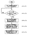
以下、転写ベルト5上の主走査方向における発光素子16aの照射範囲Pを予め検出し、その後、主走査方向において発光素子16aの照射範囲Pと重なる位置に補正用トナー画像TMnY,TMnC,TMnMを形成する方法(本発明に係る位置ずれ補正方法)について、図1のフローチャートを参照して説明する。
Hereinafter, the irradiation range P of the
位置ずれ補正処理を開始したCPU40は、第1の補正用トナー画像TM1Y,TM1C,TM1M,TM1Kと第2の補正用トナー画像TM2Y,TM2C,TM2M,TM2Kとを1組(1セット)とする最初の位置ずれ補正用パターン(第1の位置ずれ補正用パターン)を形成する(ステップ1)。但し、第1の位置ずれ補正用パターンは転写ベルト5上の主走査方向における発光素子16aの照射範囲Pを検出するためのものであるから、従来通りに主走査方向における受光素子16bの受光領域Wよりも大きい領域に形成される。第1の位置ずれ補正用パターンが検出手段によって検出され(ステップ2)、その検出結果がCPU40に入力されると、CPU40が検出手段の検出結果から求めた第1の位置ずれ補正用パターン(補正用トナー画像TMnY,TMnC,TMnM,TMnK)の主走査方向における位置と設計的に求め得る理想的な位置との差を算出することで発光素子16aの照射範囲Pを検出する(ステップ3)。そして、パターン形成手段たるCPU40は、図11に示すように検出した照射範囲Pと主走査方向において重なる位置に後続の位置ずれ補正用パターン(第2の位置ずれ補正用パターン)を複数セット連続して形成する(ステップ4)。そして、CPU40では、後続の複数の第2の位置補正用パターンを検出手段で検出した検出結果に基づいて既に説明した位置ずれ補正処理を行う(ステップ5)。尚、発光素子16aの照射範囲Pを求めるに当たって第1の位置ずれ補正用パターンを複数形成し、それら複数の第1の位置ずれ補正用パターンの検出結果を平均化して当該第1の位置ずれ補正用パターンの位置を求めるようにしても構わない。
The
上述のように転写ベルト5上の主走査方向における発光素子16aの照射範囲Pを予め検出し、その後、主走査方向において発光素子16aの照射範囲Pと重なる位置に、受光素子16bの受光領域W内の大きさで補正用トナー画像TMnY,TMnC,TMnM,TMnK(第2の位置補正用パターン)を形成すれば、拡散反射光成分が低減されるために各色の補正用トナー画像TMnK,TMnY,TMnC,TMnMの検出誤差を抑制することができ、その結果、位置ずれ補正装置における位置ずれ量の算出にスポットずれの影響が及ばず、位置ずれ補正の精度低下を防ぐことができる。しかも、第1の位置ずれ補正用パターンに比較して第2の位置補正用パターンの形成領域が小さいから、位置ずれ補正用パターンの形成に要するトナーの使用量を削減することができる。なお、上述したように黒の補正用トナー画像TMnKについては拡散反射光成分の影響を殆ど受けないので、第2の位置補正用パターンにおいては少なくとも黒以外の補正用トナー画像TMnY,TMnC,TMnMを受光素子16bの受光領域W内の大きさに形成すればよいが、トナー消費量を低減するという観点からは黒の補正用トナー画像TMnKについても受光素子16bの受光領域W内の大きさに形成することが望ましい。また、第2の位置補正用パターンの形状は図10(a)に示すような正方形状に限定されるものではない。
As described above, the irradiation range P of the
ところで、補正用トナー画像TMnY,…(n=1,2)は主走査方向の両端に配置されるために露光器11における光学系のずれ等の影響が大きく現れ、特に、ポリゴンミラー20の一の反射面で反射される光で露光されることにより形成される第2の補正用トナー画像TM2Y又はTM2Cと、ポリゴンミラー20の他の反射面で反射される光で露光されることにより形成される第2の補正用トナー画像TM2M又はTM2Kとが主走査方向に移動し、例えば、シアン用の第2の補正用トナー画像TM2Cと黒用の第2の補正用トナー画像TM2Kとが重なって正常に検出できなくなることが起こり得る。
By the way, since the correction toner images TMn Y ,... (N = 1, 2) are arranged at both ends in the main scanning direction, the influence of the deviation of the optical system in the
このように第2の補正用トナー画像TM2Yが正常に検出できない事態を回避するためには、各色毎の第2の補正用トナー画像TM2Y,TM2C,TM2M,TM2Kのうちでポリゴンミラー20の異なる反射面で同時に反射される光で露光されることにより形成される複数の補正用トナー画像同士、すなわち、ポリゴンミラー20の一の反射面で反射される光で露光されることにより形成されるイエロー用並びにシアン用の第2の補正用トナー画像TM2Y,TM2Cと、ポリゴンミラー20の他の反射面で反射される光で露光されることにより形成されるマゼンタ用並びに黒用の第2の補正用トナー画像TM2M,TM2Kとが主走査方向に沿って平行移動しても重ならない位置に配置すればよい。例えば、各色毎に第1及び第2の補正用トナー画像TMnY,TMnC,TMnM,TMnKを副走査方向に隣接して形成すれば、上述のようにポリゴンミラー20の一の反射面で反射される光で露光されることにより形成される第2の補正用トナー画像TM2Y又はTM2Cと、ポリゴンミラー20の他の反射面で反射される光で露光されることにより形成される第2の補正用トナー画像TM2M又はTM2Kとが主走査方向に移動しても、シアン用の第2の補正用トナー画像TM2Cと黒用の第2の補正用トナー画像TM2Kとが重なって正常に検出できなくなるのを防ぐことができる。さらに、第1及び第2の補正用トナー画像TMnY,TMnC,TMnM,TMnKの2種類で位置補正用パターンを形成するのではなく、図12に示すように三角形状(例えば、直角二等辺三角形状)の補正用トナー画像TMY,TMC,TMM,TMKが副走査方向に沿って一列に配置されたパターンとしても構わない。かかる補正用トナー画像TMY,TMC,TMM,TMKでは、主走査方向に平行な直線部と、主走査方向及び副走査方向と各々45度の角度で交差する直線部との間がトナーで埋められているので、例えば、転写ベルト5に付いた傷の影響を無くすことができるという利点がある。但し、第2の位置補正用パターンについては三角形状ではなく台形形状の補正用トナー画像TMY,TMC,TMM,TMKで構成する。なお、補正用トナー画像のパターンは、感光体9Y,9C,9M,9Kの半周期毎に1組の割合で各々偶数組(例えば、16組)が、主走査方向における両端と中央に副走査方向に沿って一列に並べて形成されている。このように感光体9Y,9C,9M,9Kの半周期の間隔を開けて形成する理由は、感光体9Y,9C,9M,9Kの1周期の位置ずれ量の変動が正弦波を描くとみなすと、半周期間隔の対の補正用トナー画像TMnY,TMnC,TMnM,TMnKを検出して平均化すれば、理論上常にずれ変動の中央値を検出できる(変動分がキャンセルされる)からである(例えば、特開平11−65208号公報参照)。
In order to avoid the situation in which the second correction toner image TM2 Y cannot be normally detected in this way, the polygon among the second correction toner images TM2 Y , TM2 C , TM2 M , and TM2 K for each color is used. A plurality of correction toner images formed by being exposed to light reflected simultaneously from different reflecting surfaces of the
ところで、位置ずれ補正処理は印刷時に毎回行うのではなく、画像形成装置(カラーレーザビームプリンタ)の電源投入時や数百回の印刷毎に1回というような割合で行うのが一般的である。そして、上述のように転写ベルト5上の主走査方向における発光素子16aの照射範囲Pを検出する処理についても、毎回の位置ずれ補正処理時に行うのではなく、前回の検出結果を利用することで数回の位置ずれ補正処理に1回というような割合で行うようにしてもよい。また、画像形成装置の製造段階で転写ベルト5上の主走査方向における発光素子16aの照射範囲Pを予め検出するとともに当該検出結果をメモリに記憶させておき、位置ずれ補正処理時にはメモリに記憶されている検出結果を利用するようにしても構わない。何れの場合においても、転写ベルト5上の主走査方向における発光素子16aの照射範囲Pを検出する必要がないから、第1の位置ずれ補正用パターンを形成せずに第2の位置ずれ補正用パターンのみを形成すればよい。
By the way, the misregistration correction processing is generally not performed every time printing is performed, but is performed at a rate of once every time the image forming apparatus (color laser beam printer) is turned on or every several hundreds of times of printing. . As described above, the process of detecting the irradiation range P of the
なお、本実施形態では画像プロセス部6から転写紙4に直接トナー画像を転写する方式の画像形成装置を例示したが、これに限定する趣旨ではなく、図13に示すように全てのトナー画像を一旦中間転写ベルト5’に転写した後、中間転写ベルト5’から転写紙4に2次転写する方式の画像形成装置にも本発明の技術思想が適用可能であることは説明するまでもない。
In the present embodiment, the image forming apparatus of the type that directly transfers the toner image from the image processing unit 6 to the
5 転写ベルト
11 露光器
16 検出器
40 CPU
5
Claims (13)
露光手段、現像手段、転写手段によって転写体に形成される各色毎の現像剤像からなる位置ずれ補正用パターンを光学的に検出するとともに、検出された各色の位置ずれ補正用パターンの相対的な位置関係に基づいて露光手段を制御することにより転写体に転写される各色の現像剤像同士の位置ずれを補正する位置ずれ補正装置において、
転写体に向けて光を出射する発光素子及び当該光が転写体並びに位置ずれ補正用パターンに反射した反射光を受光する単一の受光素子を有する検出手段と、転写体の搬送方向に沿って並ぶ複数の位置ずれ補正用パターンを画像形成装置に形成させるパターン形成手段とを備え、
パターン形成手段は、転写体上における前記発光素子の照射範囲を検出する第1の位置ずれ補正用パターンを画像形成装置に形成させ、検出手段の検出結果に基づいて前記第1の位置ずれ補正用パターンの当該搬送方向に直交する方向における位置を求めるとともに当該位置に基づいて、前記直交方向に沿った位置ずれ補正用パターンの形成領域が、転写体上における受光素子の受光領域内となるように、前記第1の位置ずれ補正用パターンの後の第2の位置ずれ補正用パターンを画像形成装置に形成させることを特徴とする位置ずれ補正装置。 A plurality of image carriers arranged in a line along the transfer direction of the transfer member, an exposure unit that forms an electrostatic latent image by exposing each charged image carrier, and each image carrier A plurality of developing means for developing the electrostatic latent image with different color developers, a conveying means for conveying the transfer body, and a developer for each color that has developed the electrostatic latent image on the image carrier are transferred to the transfer body. And an image forming apparatus having a transfer means for forming a developer image.
A positional deviation correction pattern composed of a developer image for each color formed on the transfer body by the exposure means, the developing means, and the transfer means is optically detected, and the detected positional deviation correction pattern for each color is relatively detected. In a misregistration correction apparatus that corrects misregistration between developer images of respective colors transferred to a transfer body by controlling an exposure unit based on a positional relationship.
A light-emitting element that emits light toward the transfer body, a detection unit that includes a single light-receiving element that receives reflected light reflected by the transfer body and the positional deviation correction pattern, and a transfer body along the transfer direction of the transfer body A pattern forming unit that causes the image forming apparatus to form a plurality of aligned misalignment correction patterns
The pattern forming unit causes the image forming apparatus to form a first misregistration correction pattern for detecting the irradiation range of the light emitting element on the transfer body, and based on the detection result of the detection unit, the first misregistration correction The position of the pattern in the direction orthogonal to the conveyance direction is obtained, and based on the position, the misalignment correction pattern forming area along the orthogonal direction is within the light receiving area of the light receiving element on the transfer body. A misregistration correction apparatus that causes the image forming apparatus to form a second misregistration correction pattern after the first misregistration correction pattern.
パターン形成手段は、検出手段による第1パターン及び第2パターンの検出結果に基づいて第1の位置ずれ補正用パターンの直交方向における位置を求めることを特徴とする請求項1記載の位置ずれ補正装置。 The first misregistration correction pattern includes a belt-like first pattern parallel to the orthogonal direction and a belt-like first pattern that is inclined at a predetermined inclination angle that is greater than 0 degree and less than 90 degrees with respect to the transfer body conveyance direction. It consists of two patterns,
2. The positional deviation correction apparatus according to claim 1, wherein the pattern forming means obtains the position in the orthogonal direction of the first positional deviation correction pattern based on the detection result of the first pattern and the second pattern by the detection means. .
パターン形成手段は、少なくとも黒色以外の現像剤像によって第2の位置ずれ補正用パターンを画像形成装置に形成させることを特徴とする請求項1〜11の何れか1項に記載の位置ずれ補正装置。 Developing means includes those using a black developer and those using a developer other than black,
12. The positional deviation correction apparatus according to claim 1, wherein the pattern forming unit causes the image forming apparatus to form a second positional deviation correction pattern using at least a developer image other than black. .
Priority Applications (2)
| Application Number | Priority Date | Filing Date | Title |
|---|---|---|---|
| JP2007240830A JP5181594B2 (en) | 2007-09-18 | 2007-09-18 | Misalignment correction apparatus and image forming apparatus |
| US12/210,491 US7986907B2 (en) | 2007-09-18 | 2008-09-15 | Positional misalignment correcting device and image forming apparatus |
Applications Claiming Priority (1)
| Application Number | Priority Date | Filing Date | Title |
|---|---|---|---|
| JP2007240830A JP5181594B2 (en) | 2007-09-18 | 2007-09-18 | Misalignment correction apparatus and image forming apparatus |
Publications (3)
| Publication Number | Publication Date |
|---|---|
| JP2009069767A JP2009069767A (en) | 2009-04-02 |
| JP2009069767A5 JP2009069767A5 (en) | 2010-07-29 |
| JP5181594B2 true JP5181594B2 (en) | 2013-04-10 |
Family
ID=40454617
Family Applications (1)
| Application Number | Title | Priority Date | Filing Date |
|---|---|---|---|
| JP2007240830A Expired - Fee Related JP5181594B2 (en) | 2007-09-18 | 2007-09-18 | Misalignment correction apparatus and image forming apparatus |
Country Status (2)
| Country | Link |
|---|---|
| US (1) | US7986907B2 (en) |
| JP (1) | JP5181594B2 (en) |
Families Citing this family (28)
| Publication number | Priority date | Publication date | Assignee | Title |
|---|---|---|---|---|
| JP5206339B2 (en) * | 2007-12-19 | 2013-06-12 | 株式会社リコー | Position shift amount detection device, position shift amount detection method, position shift amount detection program |
| JP5061044B2 (en) * | 2008-06-25 | 2012-10-31 | 株式会社リコー | Image forming apparatus |
| JP4873265B2 (en) * | 2008-09-29 | 2012-02-08 | ブラザー工業株式会社 | Image forming apparatus |
| JP5381187B2 (en) | 2009-03-13 | 2014-01-08 | 株式会社リコー | Image forming apparatus |
| JP5434694B2 (en) * | 2009-03-18 | 2014-03-05 | 株式会社リコー | Misalignment correction method, misalignment correction apparatus, and image forming apparatus using the same |
| JP2010250088A (en) * | 2009-04-16 | 2010-11-04 | Konica Minolta Business Technologies Inc | Intermediate transfer member, method for manufacturing intermediate transfer member, and image forming apparatus |
| JP5598154B2 (en) * | 2009-08-27 | 2014-10-01 | 株式会社リコー | Image forming apparatus and density correction method thereof |
| JP5397282B2 (en) | 2010-03-17 | 2014-01-22 | 株式会社リコー | Misalignment correction apparatus and image forming apparatus having the same |
| JP5246289B2 (en) * | 2011-03-31 | 2013-07-24 | ブラザー工業株式会社 | Image forming apparatus and image adjusting method |
| US20120275811A1 (en) * | 2011-04-26 | 2012-11-01 | Toshiba Tec Kabushiki Kaisha | Color image forming apparatus including function of correcting color drift of image and color image forming method |
| JP6041518B2 (en) * | 2012-04-13 | 2016-12-07 | キヤノン株式会社 | Image forming apparatus |
| JP6015311B2 (en) * | 2012-09-28 | 2016-10-26 | 富士ゼロックス株式会社 | Image forming apparatus and program |
| JP6191126B2 (en) | 2012-11-30 | 2017-09-06 | 株式会社リコー | Optical writing control apparatus, image forming apparatus, and optical writing apparatus control method |
| JP6079178B2 (en) * | 2012-12-03 | 2017-02-15 | 株式会社リコー | Optical writing control apparatus, image forming apparatus, and optical writing apparatus control method |
| JP6130659B2 (en) * | 2012-12-19 | 2017-05-17 | キヤノン株式会社 | Image forming apparatus and detection apparatus |
| JP2014119731A (en) * | 2012-12-19 | 2014-06-30 | Canon Inc | Image forming apparatus and detecting device |
| US9576229B2 (en) * | 2012-12-19 | 2017-02-21 | Canon Kabushiki Kaisha | Image forming apparatus and detection apparatus |
| US9885990B2 (en) | 2012-12-19 | 2018-02-06 | Canon Kabushiki Kaisha | Image forming apparatus and detection apparatus for detecting position or density information of detection image |
| JP2014140972A (en) | 2013-01-22 | 2014-08-07 | Ricoh Co Ltd | Image formation control device, image formation device, and image formation control method |
| JP6135186B2 (en) * | 2013-02-28 | 2017-05-31 | 株式会社リコー | Optical writing control apparatus, image forming apparatus, and optical writing apparatus control method |
| KR102144316B1 (en) * | 2013-07-18 | 2020-08-13 | 휴렛-팩커드 디벨롭먼트 컴퍼니, 엘.피. | Image forming apparatus and method for color registration correction |
| JP2015034884A (en) | 2013-08-08 | 2015-02-19 | 株式会社リコー | Optical writing control device, image forming apparatus, and control method of optical writing device |
| JP6171772B2 (en) * | 2013-09-17 | 2017-08-02 | 株式会社リコー | Optical writing control apparatus, image forming apparatus, and optical writing apparatus control method |
| JP6232959B2 (en) | 2013-11-18 | 2017-11-22 | 株式会社リコー | Optical writing control apparatus, image forming apparatus, and optical writing apparatus control method |
| JP6428084B2 (en) | 2014-09-17 | 2018-11-28 | 株式会社リコー | Write control apparatus, image forming apparatus, write control method, and program |
| JP2016061896A (en) | 2014-09-17 | 2016-04-25 | 株式会社リコー | Writing control device, image forming apparatus, writing control method, and program |
| US9817350B2 (en) | 2014-12-15 | 2017-11-14 | Ricoh Company, Limited | Positional deviation correction pattern, method of forming positional deviation correction pattern, and image forming apparatus |
| US10761467B1 (en) * | 2019-08-27 | 2020-09-01 | Toshiba Tec Kabushiki Kaisha | Image forming apparatus and image position adjustment method |
Family Cites Families (27)
| Publication number | Priority date | Publication date | Assignee | Title |
|---|---|---|---|---|
| JPH0296774A (en) * | 1988-10-04 | 1990-04-09 | Canon Inc | Image forming device |
| JP3275434B2 (en) * | 1993-03-29 | 2002-04-15 | 富士ゼロックス株式会社 | Color registration error correction device |
| JP3616295B2 (en) * | 2000-01-18 | 2005-02-02 | シャープ株式会社 | Image forming apparatus |
| JP2002202651A (en) * | 2000-12-28 | 2002-07-19 | Casio Electronics Co Ltd | Device and method for adjusting color image forming position and recording medium recording its program |
| JP4745512B2 (en) | 2001-02-09 | 2011-08-10 | キヤノン株式会社 | Color image forming apparatus |
| US20050104950A1 (en) * | 2001-09-04 | 2005-05-19 | Samsung Electronics Co., Ltd. | Apparatus to control color registration and image density using a single mark and method using the same |
| JP3604683B2 (en) * | 2002-09-24 | 2004-12-22 | 株式会社リコー | Color image forming apparatus, tandem drum type color image forming apparatus, and process cartridge used in color image forming apparatus |
| DE60323454D1 (en) * | 2002-11-29 | 2008-10-23 | Ricoh Kk | Method for determining the minimum usable measuring surface of a sensor for alignment patterns in an image forming apparatus |
| JP2004347999A (en) * | 2003-05-23 | 2004-12-09 | Konica Minolta Business Technologies Inc | Image forming apparatus and image forming method |
| JP2005031227A (en) | 2003-07-09 | 2005-02-03 | Ricoh Co Ltd | Misregistration correcting pattern formation method, misregistration correcting device, image forming apparatus, misregistration correction method, computer program and recording medium |
| US7162171B2 (en) * | 2003-08-22 | 2007-01-09 | Ricoh Company, Ltd. | Method, system and software program for correcting positional color misalignment |
| JP4269914B2 (en) * | 2003-12-03 | 2009-05-27 | 富士ゼロックス株式会社 | Image forming apparatus |
| JP2005233983A (en) * | 2004-02-17 | 2005-09-02 | Fuji Xerox Co Ltd | Image forming apparatus and the method |
| JP4515831B2 (en) * | 2004-06-14 | 2010-08-04 | 株式会社リコー | Development density control method and image forming apparatus |
| JP4745723B2 (en) * | 2005-06-06 | 2011-08-10 | キヤノン株式会社 | Image forming apparatus |
| JP2007003986A (en) | 2005-06-27 | 2007-01-11 | Ricoh Co Ltd | Color image forming device |
| JP2007078778A (en) * | 2005-09-12 | 2007-03-29 | Matsushita Electric Ind Co Ltd | Image forming apparatus and method for forming color deviation detection pattern for image forming apparatus |
| JP2007140135A (en) * | 2005-11-18 | 2007-06-07 | Matsushita Electric Ind Co Ltd | Color image forming apparatus |
| JP2007316237A (en) * | 2006-05-24 | 2007-12-06 | Fuji Xerox Co Ltd | Image forming apparatus and density correction method |
| JP2007322772A (en) * | 2006-06-01 | 2007-12-13 | Fuji Xerox Co Ltd | Image forming apparatus |
| JP5062808B2 (en) * | 2006-08-08 | 2012-10-31 | 株式会社リコー | Misalignment correction apparatus and method, and image forming apparatus |
| JP4963390B2 (en) * | 2006-09-19 | 2012-06-27 | 株式会社リコー | Misalignment correction apparatus and color image forming apparatus |
| JP4966026B2 (en) * | 2007-01-11 | 2012-07-04 | 株式会社リコー | Image forming method, image forming apparatus, and correction toner image pattern |
| JP4966025B2 (en) * | 2007-01-11 | 2012-07-04 | 株式会社リコー | Image forming method and image forming apparatus |
| JP2008180946A (en) * | 2007-01-25 | 2008-08-07 | Ricoh Co Ltd | Image forming method, image forming apparatus, and program for image forming apparatus |
| JP4058648B1 (en) * | 2007-03-30 | 2008-03-12 | 富士ゼロックス株式会社 | Color image forming apparatus |
| JP4501082B2 (en) * | 2007-05-25 | 2010-07-14 | ブラザー工業株式会社 | Image forming apparatus |
-
2007
- 2007-09-18 JP JP2007240830A patent/JP5181594B2/en not_active Expired - Fee Related
-
2008
- 2008-09-15 US US12/210,491 patent/US7986907B2/en not_active Expired - Fee Related
Also Published As
| Publication number | Publication date |
|---|---|
| JP2009069767A (en) | 2009-04-02 |
| US20090074476A1 (en) | 2009-03-19 |
| US7986907B2 (en) | 2011-07-26 |
Similar Documents
| Publication | Publication Date | Title |
|---|---|---|
| JP5181594B2 (en) | Misalignment correction apparatus and image forming apparatus | |
| JP4966025B2 (en) | Image forming method and image forming apparatus | |
| JP4966026B2 (en) | Image forming method, image forming apparatus, and correction toner image pattern | |
| JP2008180946A (en) | Image forming method, image forming apparatus, and program for image forming apparatus | |
| US7917045B2 (en) | Image forming apparatus and image forming method | |
| JP4710702B2 (en) | Color image forming apparatus | |
| JP5434694B2 (en) | Misalignment correction method, misalignment correction apparatus, and image forming apparatus using the same | |
| JP5807345B2 (en) | Image forming apparatus | |
| JP5400920B2 (en) | Image forming apparatus | |
| JP2010217325A (en) | Image forming device and positional deviation correction method | |
| JP2011191336A (en) | Image forming apparatus and program for cleaning time optimization control | |
| JP2007293047A (en) | Color image forming apparatus and color image forming method | |
| JP5397282B2 (en) | Misalignment correction apparatus and image forming apparatus having the same | |
| KR101678260B1 (en) | Image forming apparatus | |
| JP4950799B2 (en) | Image forming apparatus | |
| JP7433985B2 (en) | Image forming device | |
| JP2014021242A (en) | Image forming apparatus and image forming method | |
| JP5636780B2 (en) | Image forming apparatus | |
| JP4738002B2 (en) | Image forming apparatus | |
| JP2006130740A (en) | Image forming apparatus and method of forming image | |
| JP5321370B2 (en) | Optical writing apparatus, image forming apparatus, and positional deviation correction method for optical writing apparatus | |
| JP6834806B2 (en) | Image forming device | |
| JP2010217728A (en) | Optical scanner and image forming apparatus | |
| JP2006137132A (en) | Image forming apparatus including correcting method of scanning line positional deviation | |
| JP2014048338A (en) | Image forming device and image forming method |
Legal Events
| Date | Code | Title | Description |
|---|---|---|---|
| A521 | Request for written amendment filed |
Free format text: JAPANESE INTERMEDIATE CODE: A523 Effective date: 20100609 |
|
| A621 | Written request for application examination |
Free format text: JAPANESE INTERMEDIATE CODE: A621 Effective date: 20100609 |
|
| RD02 | Notification of acceptance of power of attorney |
Free format text: JAPANESE INTERMEDIATE CODE: A7422 Effective date: 20100609 |
|
| A977 | Report on retrieval |
Free format text: JAPANESE INTERMEDIATE CODE: A971007 Effective date: 20120307 |
|
| A131 | Notification of reasons for refusal |
Free format text: JAPANESE INTERMEDIATE CODE: A131 Effective date: 20120313 |
|
| A521 | Request for written amendment filed |
Free format text: JAPANESE INTERMEDIATE CODE: A523 Effective date: 20120514 |
|
| A131 | Notification of reasons for refusal |
Free format text: JAPANESE INTERMEDIATE CODE: A131 Effective date: 20121002 |
|
| A521 | Request for written amendment filed |
Free format text: JAPANESE INTERMEDIATE CODE: A523 Effective date: 20121127 |
|
| TRDD | Decision of grant or rejection written | ||
| A01 | Written decision to grant a patent or to grant a registration (utility model) |
Free format text: JAPANESE INTERMEDIATE CODE: A01 Effective date: 20121218 |
|
| A61 | First payment of annual fees (during grant procedure) |
Free format text: JAPANESE INTERMEDIATE CODE: A61 Effective date: 20121231 |
|
| R151 | Written notification of patent or utility model registration |
Ref document number: 5181594 Country of ref document: JP Free format text: JAPANESE INTERMEDIATE CODE: R151 |
|
| FPAY | Renewal fee payment (event date is renewal date of database) |
Free format text: PAYMENT UNTIL: 20160125 Year of fee payment: 3 |
|
| LAPS | Cancellation because of no payment of annual fees |