JP4966025B2 - Image forming method and image forming apparatus - Google Patents
Image forming method and image forming apparatus Download PDFInfo
- Publication number
- JP4966025B2 JP4966025B2 JP2007003913A JP2007003913A JP4966025B2 JP 4966025 B2 JP4966025 B2 JP 4966025B2 JP 2007003913 A JP2007003913 A JP 2007003913A JP 2007003913 A JP2007003913 A JP 2007003913A JP 4966025 B2 JP4966025 B2 JP 4966025B2
- Authority
- JP
- Japan
- Prior art keywords
- color
- correction
- transfer medium
- image forming
- image
- Prior art date
- Legal status (The legal status is an assumption and is not a legal conclusion. Google has not performed a legal analysis and makes no representation as to the accuracy of the status listed.)
- Expired - Fee Related
Links
Images


Classifications
-
- G—PHYSICS
- G03—PHOTOGRAPHY; CINEMATOGRAPHY; ANALOGOUS TECHNIQUES USING WAVES OTHER THAN OPTICAL WAVES; ELECTROGRAPHY; HOLOGRAPHY
- G03G—ELECTROGRAPHY; ELECTROPHOTOGRAPHY; MAGNETOGRAPHY
- G03G15/00—Apparatus for electrographic processes using a charge pattern
- G03G15/01—Apparatus for electrographic processes using a charge pattern for producing multicoloured copies
- G03G15/0142—Structure of complete machines
- G03G15/0178—Structure of complete machines using more than one reusable electrographic recording member, e.g. one for every monocolour image
- G03G15/0194—Structure of complete machines using more than one reusable electrographic recording member, e.g. one for every monocolour image primary transfer to the final recording medium
-
- G—PHYSICS
- G03—PHOTOGRAPHY; CINEMATOGRAPHY; ANALOGOUS TECHNIQUES USING WAVES OTHER THAN OPTICAL WAVES; ELECTROGRAPHY; HOLOGRAPHY
- G03G—ELECTROGRAPHY; ELECTROPHOTOGRAPHY; MAGNETOGRAPHY
- G03G15/00—Apparatus for electrographic processes using a charge pattern
- G03G15/01—Apparatus for electrographic processes using a charge pattern for producing multicoloured copies
- G03G15/0142—Structure of complete machines
- G03G15/0178—Structure of complete machines using more than one reusable electrographic recording member, e.g. one for every monocolour image
- G03G15/0189—Structure of complete machines using more than one reusable electrographic recording member, e.g. one for every monocolour image primary transfer to an intermediate transfer belt
-
- G—PHYSICS
- G03—PHOTOGRAPHY; CINEMATOGRAPHY; ANALOGOUS TECHNIQUES USING WAVES OTHER THAN OPTICAL WAVES; ELECTROGRAPHY; HOLOGRAPHY
- G03G—ELECTROGRAPHY; ELECTROPHOTOGRAPHY; MAGNETOGRAPHY
- G03G2215/00—Apparatus for electrophotographic processes
- G03G2215/01—Apparatus for electrophotographic processes for producing multicoloured copies
- G03G2215/0103—Plural electrographic recording members
- G03G2215/0119—Linear arrangement adjacent plural transfer points
- G03G2215/0122—Linear arrangement adjacent plural transfer points primary transfer to an intermediate transfer belt
- G03G2215/0125—Linear arrangement adjacent plural transfer points primary transfer to an intermediate transfer belt the linear arrangement being horizontal or slanted
- G03G2215/0132—Linear arrangement adjacent plural transfer points primary transfer to an intermediate transfer belt the linear arrangement being horizontal or slanted vertical medium transport path at the secondary transfer
-
- G—PHYSICS
- G03—PHOTOGRAPHY; CINEMATOGRAPHY; ANALOGOUS TECHNIQUES USING WAVES OTHER THAN OPTICAL WAVES; ELECTROGRAPHY; HOLOGRAPHY
- G03G—ELECTROGRAPHY; ELECTROPHOTOGRAPHY; MAGNETOGRAPHY
- G03G2215/00—Apparatus for electrophotographic processes
- G03G2215/01—Apparatus for electrophotographic processes for producing multicoloured copies
- G03G2215/0151—Apparatus for electrophotographic processes for producing multicoloured copies characterised by the technical problem
- G03G2215/0158—Colour registration
- G03G2215/0161—Generation of registration marks
Description
本発明は、静電写真方式の画像形成方法並びに画像形成装置、補正用トナー画像のパターンに関し、特に、転写体に形成される複数色のトナー画像同士の位置ずれに起因した色ずれを補正するようにした画像形成方法並びに画像形成装置に関するものである。 The present invention relates to an electrophotographic image forming method, an image forming apparatus, and a correction toner image pattern. In particular, the present invention corrects color misregistration caused by misregistration between a plurality of color toner images formed on a transfer body. those related as the image forming method and image forming equipment was.
カラー複写機やカラーレーザプリンタに代表される画像形成装置のうち、特にタンデム方式の画像形成装置においては、イエロー、シアン、マゼンタ、黒の4色のトナーによるトナー画像を各色用の感光体から転写体(転写ベルト又は転写紙)に順次重ねて転写するため、各色のトナー画像の位置が相対的にずれることで色ずれの発生する虞がある。かかる色ずれは各色のトナー画像を転写紙に定着して形成されるカラー画像の品質に大きく影響するものであるから、この種の画像形成装置では色ずれを抑制することが重要な技術課題となっている。 Among image forming apparatuses represented by color copiers and color laser printers, in particular, in tandem image forming apparatuses, toner images of four colors of yellow, cyan, magenta, and black are transferred from a photoconductor for each color. Since the images are sequentially superimposed and transferred onto the body (transfer belt or transfer paper), there is a risk that color misregistration may occur due to the relative displacement of the positions of the toner images of the respective colors. Since such color misregistration greatly affects the quality of the color image formed by fixing the toner images of the respective colors on the transfer paper, it is an important technical problem to suppress the color misregistration in this type of image forming apparatus. It has become.
そこで従来は、転写紙4を搬送する搬送ベルト上に図12(a)に示すような各色(イエロー、シアン、マゼンタ、黒)の補正用トナー画像TMnY,TMnC,TMnM,TMnKを形成し(n=1,2)、これらの補正用トナー画像TMnY,TMnC,TMnM,TMnKを光学的な検出手段で検出するとともに、検出手段による検出結果から各色のトナー画像間に生じている位置ずれ量を求め、露光器における露光開始時間の設定を変更する等の方法で位置ずれ(色ずれ)を補正している(例えば、特許文献1等参照)。
ところで、各色用の感光体を露光する露光器では、図4に示すようにレーザ光源LD1〜LD4から出射されたレーザ光を多面体鏡(ポリゴンミラー)20の反射面で反射させる際、ポリゴンミラー20を回転させることで円筒形状の各感光体の表面を軸方向に沿って露光する主走査を行うとともに、感光体が軸回りに回転することで周方向(転写体の搬送方向)に沿って露光する副走査が行われる。ここで、図4に示す露光器11においては、イエロー用の感光体9Yとシアン用の感光体9Cをそれぞれ露光するためにレーザ光源LD1,LD2から出射されるレーザ光がポリゴンミラー20の一の反射面で同時に反射され、同じくマゼンタ用の感光体9Mと黒用の感光体9Kをそれぞれ露光するためにレーザ光源LD3,LD4から出射されるレーザ光がポリゴンミラー20の他の反射面で同時に反射されるようになっている。
By the way, in the exposure device that exposes the photoconductors for the respective colors, when the laser light emitted from the laser light sources LD1 to LD4 is reflected by the reflecting surface of the polyhedral mirror (polygon mirror) 20, as shown in FIG. Rotate the main body to expose the surface of each cylindrical photoconductor along the axial direction, and rotate along the circumferential direction (transfer body conveyance direction) as the photoconductor rotates about the axis. Sub-scanning is performed. Here, in the
ここで、従来の補正用トナー画像のパターンは、主走査方向及び副走査方向と各々45度の角度で交差する直線部を有した短冊状のもの(以下、第1の補正用トナー画像TM1Y,TM1C,TM1M,TM1Kと呼ぶ。)と、主走査方向に平行な直線部を有した短冊状のもの(以下、第2の補正用トナー画像TM2Y,TM2C,TM2M,TM2Kと呼ぶ。)とが所定の間隔を開けて副走査方向に一列に並べて形成されている(図12(a)参照)。かかる従来例においては、補正用トナー画像のパターンが主走査方向の両端に配置されるために露光器における光学系のずれ等の影響が大きく現れ、特に、ポリゴンミラー20の一の反射面で反射される光で露光されることにより形成される第1の補正用トナー画像TM1Y又はTM1Cと、ポリゴンミラー20の他の反射面で反射される光で露光されることにより形成される第1の補正用トナー画像TM1M又はTM1Kとが主走査方向に移動し、例えば、図12(b)に示すようにシアン用の第1の補正用トナー画像TM1Cと黒用の第1の補正用トナー画像TM1Kとが重なって正常に検出できなくなる虞があった。
Here, the pattern of the conventional correction toner image has a strip shape having straight portions intersecting with the main scanning direction and the sub-scanning direction at an angle of 45 degrees (hereinafter, referred to as the first correction toner image TM1 Y). , TM1 C , TM1 M , TM1 K ) and a strip-like one having a linear portion parallel to the main scanning direction (hereinafter, second correction toner images TM2 Y , TM2 C , TM2 M , TM2). (Referred to as “ K” ) arranged in a line in the sub-scanning direction at a predetermined interval (see FIG. 12A). In such a conventional example, since the pattern of the correction toner image is arranged at both ends in the main scanning direction, the influence of the deviation of the optical system in the exposure device appears greatly. The first correction toner image TM1 Y or TM1 C formed by being exposed with the light to be applied and the first toner image formed by being exposed with the light reflected by the other reflecting surface of the
本発明は上記事情に鑑みて為されたものであり、その目的は、各色用の補正用トナー画像が重なって検出できなくなることを防止した画像形成方法並びに画像形成装置、補正用トナー画像のパターンを提供することにある。 The present invention has been made in view of the above circumstances, and an object of the present invention is to provide an image forming method, an image forming apparatus, and a correction toner image pattern that prevent correction toner images for each color from being overlapped and cannot be detected. Is to provide.
請求項1の発明は、上記目的を達成するために、複数の反射面を有する多面体鏡を一方向に回転させながら異なる反射面で同時に複数の光源の光を反射させて各色用の像担持体を露光し、それぞれに像担持体に担持された複数色のトナー画像を転写媒体に重ねて転写するとともに、転写媒体若しくは転写媒体を搬送する搬送手段に転写媒体の搬送方向に対して0度よりも大きく且つ90度よりも小さい角度で交差する第1の直線部を有した各色の補正用トナー画像からなるパターンを形成し、当該補正用トナー画像のパターンを光学的に検出することで各色のトナー画像が重なる位置を補正する画像形成方法において、前記各色の補正用トナー画像は、夫々各色で形成された斜線であり、各色毎の補正用トナー画像のうちで多面体鏡の異なる反射面にて同時に反射される光によって露光されることにより形成される複数の補正用トナー画像同士が、多面体鏡の回転によって走査される走査方向に沿って平行移動しても重ならない位置に配置されると共に、各色毎の補正用トナー画像のうちで多面体鏡の同一の反射面にて同時に反射される光によって露光されることにより形成される複数の補正用トナー画像同士が、多面体鏡の回転によって操作される操作方向に沿って平行移動すると重なる位置に配置されて補正用トナー画像のパターンが形成されることを特徴とする。 In order to achieve the above object, the invention according to claim 1, while rotating a polyhedral mirror having a plurality of reflecting surfaces in one direction, the light of a plurality of light sources is simultaneously reflected by different reflecting surfaces to thereby provide an image carrier for each color. And transferring a plurality of color toner images carried on the image carrier onto the transfer medium, and transferring the transfer medium or a transfer means for conveying the transfer medium from 0 degrees with respect to the conveyance direction of the transfer medium. And forming a pattern composed of a correction toner image of each color having a first linear portion intersecting at an angle smaller than 90 degrees and optically detecting the pattern of the correction toner image. an image forming method for correcting the position where the toner image overlap, each color correction toner images are shaded formed by the respective colors, different polygonal mirror out of the correcting toner image for each color A plurality of correction toner images formed by being exposed to light simultaneously reflected on the projection surface are arranged at positions that do not overlap even if they are translated along the scanning direction scanned by the rotation of the polyhedral mirror. is Rutotomoni, a plurality of correction toner images with each other is formed by being exposed by light reflected at the same time by the same reflecting surface of the polygonal mirror among the correcting toner image for each color, the rotation of the polyhedral mirror When a parallel movement is performed along the operation direction operated by the above, the correction toner image pattern is formed at the overlapping position .
請求項2の発明は、請求項1記載の発明において、各色毎の補正用トナー画像は、転写媒体の搬送方向に対して垂直であり且つ転写媒体の搬送方向に沿って同色の第1の直線部と異なる色の第1の直線部とに挟まれた第2の直線部を有することを特徴とする。 According to a second aspect of the present invention, in the first aspect of the invention, the correction toner image for each color is a first straight line that is perpendicular to the transfer medium conveyance direction and has the same color along the transfer medium conveyance direction. It has the 2nd straight part pinched | interposed into the 1st straight line part of a color different from a part, It is characterized by the above-mentioned.
請求項3の発明は、請求項2の発明において、第2の直線部は、転写媒体の搬送方向に対して第1の直線部よりも前方に配置されることを特徴とする。 According to a third aspect of the present invention, in the second aspect of the present invention, the second straight line portion is disposed in front of the first straight line portion in the transfer direction of the transfer medium.
請求項4の発明は、請求項2の発明において、第2の直線部は、転写媒体の搬送方向に対して第1の直線部よりも後方に配置されることを特徴とする。 According to a fourth aspect of the present invention, in the second aspect of the invention, the second straight line portion is arranged behind the first straight line portion in the transfer direction of the transfer medium.
請求項5の発明は、請求項2〜4の何れか1項の発明において、各色毎の補正用トナー画像は、三角形状に形成されることを特徴とする。 According to a fifth aspect of the invention, in the invention according to any one of the second to fourth aspects, the correction toner image for each color is formed in a triangular shape.
請求項6の発明は、請求項1〜5の何れか1項の発明において、複数の補正用トナー画像のパターンが転写媒体の搬送方向に沿って一列に配置されることを特徴とする。 According to a sixth aspect of the present invention, in any one of the first to fifth aspects, the plurality of correction toner image patterns are arranged in a line along a transfer medium conveyance direction.
請求項7の発明は、請求項6の発明において、複数のパターンを検出手段で検出した検出結果を平均して位置ずれを補正することを特徴とする。 A seventh aspect of the invention is characterized in that, in the sixth aspect of the invention, the positional deviation is corrected by averaging detection results obtained by detecting a plurality of patterns by the detecting means.
請求項8の発明は、上記目的を達成するために、複数の反射面を有する多面体鏡を一方向に回転させながら異なる反射面で同時に複数の光源の光を反射させて各色用の像担持体を露光し、それぞれに像担持体に担持された複数色のトナー画像を転写媒体に重ねて転写するとともに、転写媒体若しくは転写媒体を搬送する搬送手段に転写媒体の搬送方向に対して0度よりも大きく且つ90度よりも小さい角度で交差する第1の直線部を有した各色の補正用トナー画像からなるパターンを形成し、当該補正用トナー画像のパターンを光学的に検出することで各色のトナー画像が重なる位置を補正する画像形成装置において、前記各色の補正用トナー画像は、夫々各色で形成された斜線であり、各色毎の補正用トナー画像のうちで多面体鏡の異なる反射面にて同時に反射される光によって露光されることにより形成される複数の補正用トナー画像同士が、多面体鏡の回転によって走査される走査方向に沿って平行移動しても重ならない位置に配置されると共に、各色毎の補正用トナー画像のうちで多面体鏡の同一の反射面にて同時に反射される光によって露光されることにより形成される複数の補正用トナー画像同士が、多面体鏡の回転によって操作される操作方向に沿って平行移動すると重なる位置に配置されて補正用トナー画像のパターンが形成されることを特徴とする。 According to an eighth aspect of the present invention, in order to achieve the above object, the light of a plurality of light sources is simultaneously reflected by different reflecting surfaces while rotating a polyhedral mirror having a plurality of reflecting surfaces in one direction, and an image carrier for each color. And transferring a plurality of color toner images carried on the image carrier onto the transfer medium, and transferring the transfer medium or a transfer means for conveying the transfer medium from 0 degrees with respect to the conveyance direction of the transfer medium. And forming a pattern composed of a correction toner image of each color having a first linear portion intersecting at an angle smaller than 90 degrees and optically detecting the pattern of the correction toner image. in the image forming apparatus that corrects a position where the toner image overlap, each color correction toner images are shaded formed by the respective colors, different polygonal mirror out of the correcting toner image for each color A plurality of correction toner images formed by being exposed to light simultaneously reflected on the projection surface are arranged at positions that do not overlap even if they are translated along the scanning direction scanned by the rotation of the polyhedral mirror. is Rutotomoni, a plurality of correction toner images with each other is formed by being exposed by light reflected at the same time by the same reflecting surface of the polygonal mirror among the correcting toner image for each color, the rotation of the polyhedral mirror When a parallel movement is performed along the operation direction operated by the above, the correction toner image pattern is formed at the overlapping position .
請求項9の発明は、請求項8の発明において、各色毎の補正用トナー画像は、転写媒体の搬送方向に対して垂直であり且つ転写媒体の搬送方向に沿って同色の第1の直線部と異なる色の第1の直線部とに挟まれた第2の直線部を有することを特徴とする。 According to a ninth aspect of the present invention, in the eighth aspect of the invention, the correction toner image for each color is perpendicular to the transfer medium conveyance direction and has the same color along the transfer medium conveyance direction. And a second linear portion sandwiched between first linear portions of different colors.
請求項10の発明は、請求項9の発明において、第2の直線部は、転写媒体の搬送方向に対して第1の直線部よりも前方に配置されることを特徴とする。 According to a tenth aspect of the invention, in the ninth aspect of the invention, the second straight line portion is arranged in front of the first straight line portion with respect to the transfer medium transport direction.
請求項11の発明は、請求項9の発明において、第2の直線部は、転写媒体の搬送方向に対して第1の直線部よりも後方に配置されることを特徴とする。 According to an eleventh aspect of the invention, in the ninth aspect of the invention, the second straight line portion is arranged behind the first straight line portion in the transfer direction of the transfer medium.
請求項12の発明は、請求項9〜11の何れか1項の発明において、各色毎の補正用トナー画像は、三角形状に形成されることを特徴とする。 According to a twelfth aspect of the present invention, in the invention according to any one of the ninth to eleventh aspects, the correction toner image for each color is formed in a triangular shape.
請求項13の発明は、請求項8〜12の何れか1項の発明において、複数の補正用トナー画像のパターンが転写媒体の搬送方向に沿って一列に配置されることを特徴とする。 A thirteenth aspect of the invention is characterized in that, in the invention according to any one of the eighth to twelfth aspects, a plurality of correction toner image patterns are arranged in a line along a transfer medium conveyance direction.
請求項14の発明は、請求項13の発明において、複数のパターンを検出手段で検出した検出結果を平均して位置ずれを補正する色ずれ補正手段を備えたことを特徴とする。 A fourteenth aspect of the invention is characterized in that, in the thirteenth aspect of the invention, color misregistration correction means for correcting a positional deviation by averaging detection results obtained by detecting a plurality of patterns by the detection means.
本発明によれば、各色毎の補正用トナー画像のうちで多面体鏡の異なる反射面で同時に反射される光で露光されることにより形成される複数の補正用トナー画像同士が、多面体鏡の回転によって走査される走査方向に沿って平行移動しても重ならない位置に配置されるので、各色用の補正用トナー画像が重なって検出できなくなることを防止できる。 According to the present invention, among a plurality of correction toner images for each color, a plurality of correction toner images formed by exposure with light simultaneously reflected by different reflection surfaces of the polyhedral mirror are rotated by the polyhedral mirror. Therefore, the correction toner images for the respective colors can be prevented from being overlapped and cannot be detected because they are arranged at positions where they do not overlap even if they are translated along the scanning direction.
以下、本発明の技術思想をタンデム方式のカラーレーザビームプリンタからなる画像形成装置に適用した実施形態について、図面を参照して詳細に説明する。但し、本発明の技術思想が適用可能な画像形成装置はカラーレーザビームプリンタに限定されるものではなく、カラー複写機やファクシミリなどの静電写真方式を採用する画像形成装置全般に適用可能である。 Embodiments in which the technical idea of the present invention is applied to an image forming apparatus including a tandem color laser beam printer will be described below in detail with reference to the drawings. However, the image forming apparatus to which the technical idea of the present invention can be applied is not limited to a color laser beam printer, but can be applied to all image forming apparatuses adopting an electrophotographic system such as a color copying machine and a facsimile. .
図2は本実施形態の画像形成装置における要部の概略構成図、図3は要部のブロック図である。 FIG. 2 is a schematic configuration diagram of a main part of the image forming apparatus according to the present embodiment, and FIG. 3 is a block diagram of the main part.
各々異なる色(イエロー:Y、シアン:C、マゼンタ:M、黒:K)の画像(トナー画像)を形成する第1〜第4の画像プロセス部6Y,6C,6M,6Kが、転写体としての転写紙4を搬送する搬送ベルト5に沿って一列に配置されている。搬送ベルト5は、図示しないモータに駆動されて回転する駆動ローラ8と従動回転する従動ローラ7との間に架設されており、駆動ローラ8の回転によって図2中の矢印方向に回転駆動される。搬送ベルト5の下部には、転写紙4が収納された給紙トレイ1が設けられている。給紙トレイ1に収納された転写紙4のうちで最上位置にある転写紙4が画像形成時に搬送ベルト5に向けて給紙ローラ2によって給紙され、静電吸着によって搬送ベルト5上に吸着される。吸着された転写紙4は、第1の画像プロセス部6Yに搬送されてイエローのトナーによる画像形成が行われる。第1〜第4の画像プロセス部6Y,6C,6M,6Kは、円筒状に形成された像担持体たる感光体9Y,9C,9M,9Kと、感光体9Y,9C,9M,9Kの周囲に配置された帯電器10Y,10C,10M,10K、露光器11、現像器12Y,12C,12M,12K及び感光体クリーナ13Y,13C,13M,13Kで構成されている。
First to fourth
露光器11は、図4に示すように各感光体9Y,9C,9M,9Kと一対一に対応する合計4つのレーザ光源LD1〜LD4と、レーザ光源LD1〜LD4から出射されたレーザ光を反射させる複数の反射面を有したポリゴンミラー20と、ポリゴンミラー20で反射された反射光を感光体9Y,9C,9M,9Kの表面に集光するfθレンズ21等の光学系とを具備しており、ポリゴンミラー20を回転させることで円筒形状の各感光体9Y,9C,9M,9Kの表面を軸方向に沿って露光するとともに、感光体9Y,9C,9M,9Kが軸回りに回転することで周方向(転写紙4の搬送方向)に沿って露光する。既に説明したように、図4に示す露光器11においては、イエロー用の感光体9Yとシアン用の感光体9Cをそれぞれ露光するためにレーザ光源LD1,LD2から出射されるレーザ光がポリゴンミラー20の一の反射面で同時に反射され、同じくマゼンタ用の感光体9Mと黒用の感光体9Kをそれぞれ露光するためにレーザ光源LD3,LD4から出射されるレーザ光がポリゴンミラー20の他の反射面(前記一の反射面の正反対の反射面)で同時に反射されるようになっている。
As shown in FIG. 4, the
カラー画像の形成に際しては、あらかじめ、カラー画像読み取り装置やパーソナルコンピュータのプリンタドライバなどから与えられた色分解画像信号が、その強度レベルをもとにしてCPU40で色変換処理を受け、黒(K),マゼンタ(M),イエロー(Y),シアン(C)のカラー画像データに変換され、露光器11の書込制御部22に出力される。
In forming a color image, a color separation image signal given in advance from a color image reading device or a printer driver of a personal computer is subjected to color conversion processing by the
画像形成が開始されると、まず、各感光体9Y,9C,9M,9Kの表面が暗中にて帯電器10Y,10C,10M,10Kにより一様に帯電された後、書込制御部22がCPU40から受け取った各色のカラー画像データに基づいてレーザダイオード制御部23を介してレーザ光源LD1〜LD4から変調されたレーザビームを出射させるとともに、ポリゴンミラー制御部24を介してポリゴンミラー20を回転させることで各感光体9Y,9C,9M,9Kの表面にカラー画像データに対応したパターンが露光されて静電潜像が形成される。なお、ポリゴンミラー20によるレーザビームの主走査と転写紙4の搬送方向に対するレーザビームの副走査とは、fθレンズ21を通過したレーザビームを折り返しミラー25a,25bで反射した反射光をフォトダイオードのような受光素子26a,26bで検出し、受光素子26a,26bの出力に基づいて同期検知制御部27から書込制御部22に同期信号を出力することで同期が取られる。この他、露光器11には基準クロック信号を発生する発振器28、発振器28から出力される基準クロックを1/Mに分周する分周器29、PLL(Phase Locked Loop)回路30、PLL回路30の出力信号を1/Nに分周する分周器31で構成される従来周知のクロックジェネレータが設けられている。このクロックジェネレータは、書込制御部22によって2つの分周器29,31の分周数M,Nが任意に設定され、基準クロックの周波数をN÷Mの分周数で分周してレーザダイオード制御部23に出力する。従って、書込制御部22が設定する分周数M,Nに応じてレーザダイオード制御部23によるレーザ光源LDの発光タイミングを調整することが可能となっている。
When image formation is started, first, after the surfaces of the photoconductors 9Y, 9C, 9M, and 9K are uniformly charged by the
各感光体9Y,9C,9M,9K上に形成された静電潜像が、各現像器12Y,12C,12M,12Kにより現像されることによって各色のトナー画像が形成され、これらのトナー画像が、各色用の感光体9Y,9C,9M,9Kと転写器14Y,14C,14M,14Kの対向部である各色の転写位置において、搬送ベルト5によって順次搬送される転写紙4上に重ねる形で転写されてカラー画像が得られる。そして、転写後の転写紙4は搬送ベルト5から分離されて定着器15に送り出され、定着器15でカラー画像が定着された後、図示しない排紙部に排紙される。また、転写紙4にトナー画像を転写した後、各感光体9Y,9C,9M,9K上に残ったトナーは各感光体9Y,9C,9M,9Kに対応して設けられた感光体クリーナ13Y,13C,13M,13Kにより除去されて次の画像形成を行う準備が整えられる。
The electrostatic latent images formed on the photoconductors 9Y, 9C, 9M, and 9K are developed by the developing
ここで、各色のトナー画像を転写紙4上で重ね合わせる際の位置合わせは、給紙トレイ1から給紙されて搬送ベルト5で搬送される転写紙4が各色の転写位置に搬送されるタイミングと、各感光体9Y,9C,9M,9K上のトナー画像が転写位置に移動させられるタイミングとが各色のトナー画像について全て一致するように、露光器11による各色の露光開始時間を設定することで行われる。
Here, the alignment when the toner images of the respective colors are superimposed on the transfer paper 4 is the timing at which the transfer paper 4 fed from the paper feed tray 1 and transported by the
しかしながら、4つの感光体9Y,9C,9M,9K同士の軸間距離の誤差、感光体9Y,9C,9M,9Kの平行度誤差、折り返しミラー25a,25bなどの光学系の設置誤差、書き込みタイミング誤差等に起因して、本来重ならなければならない位置で各色のトナー画像が重ならず、各色のトナー画像間で位置がずれた画像が形成される虞がある。これらの誤差は初期的に調整を行っても、感光体9や現像器12を含む作像ユニットの交換、メンテナンス、製品の運搬等によって誤差が生じるばかりか、複数枚の画像形成後の機構の温度膨張によっても経時的に誤差が変動するため、より短いレンジで調整を行う必要が出てくる。
However, an error in the interaxial distance between the four
上述のような誤差が原因で各色のトナー画像間に生じる位置ずれ(色ずれ)には、以下の5種類があることが従来より知られている(例えば、特開平11−65208号公報、特開2002−244393号公報等参照)。 Conventionally, it is known that there are the following five types of misregistration (color misregistration) caused between the toner images of the respective colors due to the error as described above (for example, JP-A-11-65208, No. 2002-244393).
・スキュー
・副走査方向のレジストずれ
・副走査方向のピッチムラ
・主走査方向のレジストずれ
・主走査方向の倍率誤差
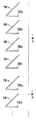
そこで、本実施形態の画像形成装置では、上記公報に記載されている従来例と同様に、転写紙4に対して実際のカラー画像形成を行うに先立ち、各色の位置ずれ補正を行っている。すなわち、搬送ベルト5上に図1に示すような各色の補正用トナー画像TMnY,TMnC,TMnM,TMnK(n=1,2)からなるパターンを形成し、当該パターンにおける補正用トナー画像TMnY,TMnC,TMnM,TMnKを検出手段で検出し、CPU40にて検出手段による検出結果から各色のトナー画像間に生じている位置ずれ量を求め、露光器11における露光開始時間の設定を変更する等の方法で位置ずれ(色ずれ)を補正している。検出手段は、搬送ベルト5に対して主走査方向の両端並びに中央に対向して設置された3つ(図3では2つのみ図示)の検出器16と、これら3つの検出器16を制御する検出器制御部17とで構成される(図3参照)。図5に示すように、検出器16は搬送ベルト5に対向配置された発光部16a並びに受光部16bで構成され、検出器制御部17で発光制御された発光部16aの出射する光が、各色のトナーよりも反射率の高い搬送ベルト5の表面で反射して受光部16bで受光されるようになっており、受光部16bにおける受光光量に対応したレベルを有する検出信号がA/D変換器54でA/D変換されてCPU40に入力されている。つまり、搬送ベルト5上に形成された補正用トナー画像TMnY,TMnC,TMnM,TMnKによって反射光の光量が減少する分だけ受光部16bの受光光量が減少するため、補正用トナー画像TMnY,TMnC,TMnM,TMnKが検出器16を通過するタイミングを検出することができる。
-Skew-Registration deviation in the sub-scanning direction-Pitch unevenness in the sub-scanning direction-Registration deviation in the main scanning direction-Magnification error in the main scanning direction Therefore, in the image forming apparatus of this embodiment, the conventional example described in the above publication Similarly, prior to the actual color image formation on the transfer paper 4, the misregistration correction of each color is performed. That is, a pattern composed of the correction toner images TMn Y , TMn C , TMn M , and TMn K (n = 1, 2) of each color as shown in FIG. 1 is formed on the
本発明の要旨である補正用トナー画像のパターンについては後に詳細に説明するので、従来周知である色ずれ補正手段による色ずれ補正について簡単に説明する。 Since the pattern of the correction toner image which is the gist of the present invention will be described in detail later, color misregistration correction by a conventionally known color misregistration correction means will be briefly described.
色ずれ補正手段は、CPU40、色ずれ補正処理用のプログラムやその他の処理用のプログラムを格納したROM41、かかるプログラムをCPU40で実行する際に必要となる作業領域を提供するRAM42などで構成されている(図3参照)。そして、ROM41に格納されている色ずれ補正処理用のプログラムをCPU40で実行することにより、色ずれ補正手段における色ずれ補正が行われる。
The color misregistration correction means includes a
CPU40では、検出器16で検出された黒の補正用トナー画像TMnKの検出位置と、他の補正用トナー画像(本実施形態ではイエロー,シアン,マゼンタの補正用トナー画像TMnY,TMnC,TMnM)の検出位置との相対的な差(時間差)と搬送ベルト5の搬送速度の設計値とから、上述した5種類の位置ずれの位置ずれ量をそれぞれ求めるとともに、求めた位置ずれ量をなくすように、以下のような補正を行う(特開2002−244393号公報等参照)。但し、各位置ずれ量の算出方法については、特開平11−65208号公報等に記載されているように従来周知であるから詳細な説明は省略する。
The
まず、スキューずれの補正について説明する。スキューずれの補正は、露光器11の折り返しミラー25a,25bの傾きを変更することによってなされる。折り返しミラー25a,25bの傾き変更は、図示しないステッピングモータで折り返しミラー25a,25bの傾き角を調整可能な機構部を駆動することで実現できる。
First, correction of skew deviation will be described. The skew deviation is corrected by changing the inclination of the folding mirrors 25a and 25b of the
また、副走査方向並びに主走査方向のレジストずれ、副走査方向のピッチムラの補正は、それぞれの位置ずれ量に応じて、同期検知制御部27から出力される同期信号に対し、レーザダイオード制御部23がレーザ光源LD1〜LD4からレーザ光を出射させるタイミング(書き出しタイミング)を早める若しくは遅らせるように、CPU40から書込制御部22に指示することで実現できる。
Further, correction of registration deviation in the sub-scanning direction and main scanning direction and pitch unevenness in the sub-scanning direction are performed on the laser
さらに、主走査方向の倍率誤差の補正は、倍率誤差のずれ量に応じて露光器11におけるクロックジェネレータから出力するクロック信号を調整させるように、CPU40から書込制御部22に指示することで実現できる。
Further, the correction of the magnification error in the main scanning direction is realized by instructing the
次に、本発明の要旨である補正用トナー画像のパターンについて説明する。 Next, a correction toner image pattern which is the gist of the present invention will be described.
既に説明したように、従来の補正用トナー画像のパターンは、主走査方向及び副走査方向と各々45度の角度で交差する直線部を有した短冊状の第1の補正用トナー画像TM1Y,TM1C,TM1M,TM1Kと、主走査方向に平行な直線部を有した短冊状の第2の補正用トナー画像TM2Y,TM2C,TM2M,TM2Kとが所定の間隔を開けて副走査方向に一列に並べて形成されている。かかる従来例においては、補正用トナー画像TMnY,…(n=1,2)が主走査方向の両端に配置されるために露光器11における光学系のずれ等の影響が大きく現れ、特に、ポリゴンミラー20の一の反射面で反射される光で露光されることにより形成される第1の補正用トナー画像TM1Y又はTM1Cと、ポリゴンミラー20の他の反射面で反射される光で露光されることにより形成される第1の補正用トナー画像TM1M又はTM1Kとが主走査方向に移動し、例えば、図12(b)に示すようにシアン用の第1の補正用トナー画像TM1Cと黒用の第1の補正用トナー画像TM1Kとが重なって正常に検出できなくなる虞があった。
As described above, the pattern of the conventional correction toner image is a strip-shaped first correction toner image TM1 Y having linear portions that intersect the main scanning direction and the sub-scanning direction at an angle of 45 degrees. TM1 C , TM1 M , TM1 K and a strip-shaped second correction toner image TM2 Y , TM2 C , TM2 M , TM2 K having a linear portion parallel to the main scanning direction are spaced apart from each other by a predetermined interval. They are arranged in a line in the sub-scanning direction. In such a conventional example, since the correction toner images TMn Y ,... (N = 1, 2) are arranged at both ends in the main scanning direction, the influence of the deviation of the optical system in the
そこで本実施形態では、図1に示すように各色毎の第1の補正用トナー画像TM1Y,TM1C,TM1M,TM1Kのうちでポリゴンミラー20の異なる反射面で同時に反射される光で露光されることにより形成される複数の補正用トナー画像同士、すなわち、ポリゴンミラー20の一の反射面で反射される光で露光されることにより形成されるイエロー用並びにシアン用の第1の補正用トナー画像TM1Y,TM1Cと、ポリゴンミラー20の他の反射面で反射される光で露光されることにより形成されるマゼンタ用並びに黒用の第1の補正用トナー画像TM1M,TM1Kとが主走査方向に沿って平行移動しても重ならない位置に配置されている。具体的には、黒用の第1の補正用トナー画像TM1Kの後端と、シアン用の第2の補正用トナー画像TM2Cの前端との間の副走査方向に沿った間隔が従来例に比較して拡がっている。従って、上述のようにポリゴンミラー20の一の反射面で反射される光で露光されることにより形成される第1の補正用トナー画像TM1Y又はTM1Cと、ポリゴンミラー20の他の反射面で反射される光で露光されることにより形成される第1の補正用トナー画像TM1M又はTM1Kとが主走査方向に移動しても、シアン用の第1の補正用トナー画像TM1Cと黒用の第1の補正用トナー画像TM1Kとが重なって正常に検出できなくなるのを防ぐことができる。なお、補正用トナー画像のパターンは、感光体9Y,9C,9M,9Kの半周期毎に1組の割合で各々偶数組(例えば、16組)が、主走査方向における両端と中央に副走査方向に沿って一列に並べて形成されている。このように感光体9Y,9C,9M,9Kの半周期の間隔を開けて形成する理由は、感光体9Y,9C,9M,9Kの1周期の位置ずれ量の変動が正弦波を描くとみなすと、半周期間隔の対の補正用トナー画像TMnY,TMnC,TMnM,TMnKを検出して平均化すれば、理論上常にずれ変動の中央値を検出できる(変動分がキャンセルされる)からである(例えば、特開平11−65208号公報参照)。
Therefore, in the present embodiment, as shown in FIG. 1, the first correction toner images TM1 Y , TM1 C , TM1 M , and TM1 K for each color are reflected simultaneously by different reflecting surfaces of the
ところで、補正用トナー画像のパターンは図1に示すものに限定されず、例えば、図6に示すようにポリゴンミラー20の一の反射面で反射される光で露光されることにより形成されるイエロー用並びにシアン用の第1及び第2の補正用トナー画像TMnY,TMnCが副走査方向に隣接して配置されるとともに、ポリゴンミラー20の他の反射面で反射される光で露光されることにより形成されるマゼンタ用並びに黒用の第1及び第2の補正用トナー画像TMnM,TMnKが副走査方向に隣接して配置されたパターンでも構わない。この場合も、黒用の第1の補正用トナー画像TM1Kの後端と、シアン用の第1の補正用トナー画像TM1Cの前端との間の副走査方向に沿った間隔が従来例に比較して拡がっているから、これらが主走査方向に平行移動しても重なることはない。
By the way, the pattern of the toner image for correction is not limited to that shown in FIG. 1, and, for example, yellow formed by exposure with light reflected by one reflecting surface of the
あるいは、図7又は図8に示すように同色用の第1及び第2の補正用トナー画像TMnY,TMnC,TMnM,TMnKが副走査方向に隣接して配置されたパターン、言い換えると、第1の補正用トナー画像TM1Y,TM1C,TM1M,TM1Kが同色の第2の補正用トナー画像TM2Y,TM2C,TM2M,TM2Kと異なる色の第2の補正用トナー画像TM2M,TM2K,TM2Y,TM2Cとに挟まれたパターンでも構わない。この場合も、黒用の第1の補正用トナー画像TM1Kの後端と、シアン用の第1の補正用トナー画像TM1Cの前端との間の副走査方向に沿った間隔が従来例に比較して拡がっているから、これらが主走査方向に平行移動しても重なることはない。 Alternatively, as shown in FIG. 7 or FIG. 8, a pattern in which the first and second correction toner images TMn Y , TMn C , TMn M , and TMn K for the same color are arranged adjacent to each other in the sub-scanning direction, in other words, The first correction toner images TM1 Y , TM1 C , TM1 M , TM1 K have the same color as the second correction toner images TM2 Y , TM2 C , TM2 M , TM2 K and the second correction toner having a different color. image TM2 M, TM2 K, TM2 Y , may be a pattern sandwiched between TM2 C. Again, the rear end of the first correction toner image TM1 K for black, the interval conventional example along the sub-scanning direction between the front end of the first correction toner image TM1 C for cyan Since they are expanded in comparison, they do not overlap even if they are translated in the main scanning direction.
また、第1及び第2の補正用トナー画像TMnY,TMnC,TMnM,TMnKの2種類でパターンを形成するのではなく、図9又は図10に示すように三角形状(例えば、直角二等辺三角形状)の補正用トナー画像TMY,TMC,TMM,TMKが副走査方向に沿って一列に配置されたパターンとしても構わない。かかる補正用トナー画像TMY,TMC,TMM,TMKでは、主走査方向に平行な直線部と、主走査方向及び副走査方向と各々45度の角度で交差する直線部との間がトナーで埋められているので、例えば、搬送ベルト5に付いた傷の影響を無くすことができるという利点がある。
Further, instead of forming a pattern with two types of first and second correction toner images TMn Y , TMn C , TMn M , and TMn K , as shown in FIG. 9 or FIG. correction toner image TM Y of isosceles triangle), TM C, TM M, TM K is may be a pattern arranged in a line along the sub-scanning direction. Such correction toner image TM Y, TM C, TM M , the TM K, a linear portion parallel to the main scanning direction, is between the linear portions which intersect at an angle in the main scanning direction and the sub scanning direction and each 45 degrees Since it is filled with toner, for example, there is an advantage that the influence of scratches on the
なお、本実施形態では画像プロセス部6から転写紙4に直接トナー画像を転写する方式の画像形成装置を例示したが、これに限定する趣旨ではなく、図11に示すように全てのトナー画像を一旦中間転写ベルト5’に転写した後、中間転写ベルト5’から転写紙4に2次転写する方式の画像形成装置にも本発明の技術思想が適用可能であることは説明するまでもない。
In the present embodiment, the image forming apparatus of the type in which the toner image is directly transferred from the image processing unit 6 to the transfer paper 4 is illustrated, but the present invention is not limited to this, and all the toner images are displayed as shown in FIG. Needless to say, the technical idea of the present invention can also be applied to an image forming apparatus in which the image is once transferred to the
TM1Y〜TM1K 第1の補正用トナー画像
TM2Y〜TM2K 第2の補正用トナー画像
TM1 Y to TM1 K first correction toner image TM2 Y to TM2 K second correction toner image
Claims (14)
前記各色の補正用トナー画像は、夫々各色で形成された斜線であり、
各色毎の補正用トナー画像のうちで多面体鏡の異なる反射面にて同時に反射される光によって露光されることにより形成される複数の補正用トナー画像同士が、多面体鏡の回転によって走査される走査方向に沿って平行移動しても重ならない位置に配置されると共に、各色毎の補正用トナー画像のうちで多面体鏡の同一の反射面にて同時に反射される光によって露光されることにより形成される複数の補正用トナー画像同士が、多面体鏡の回転によって操作される操作方向に沿って平行移動すると重なる位置に配置されて補正用トナー画像のパターンが形成されることを特徴とする画像形成方法。 While rotating a polyhedral mirror having a plurality of reflecting surfaces in one direction, the light of a plurality of light sources is simultaneously reflected by different reflecting surfaces to expose the image bearing members for each color, and the plurality of colors carried on the image bearing members respectively. The toner image is superimposed on the transfer medium and transferred to the transfer medium or the transfer means for transferring the transfer medium at a first angle that intersects the transfer direction of the transfer medium at an angle greater than 0 degrees and less than 90 degrees. In an image forming method for correcting a position where toner images of respective colors overlap by forming a pattern made of a correction toner image of each color having a linear portion and optically detecting the pattern of the correction toner image.
The correction toner images of the respective colors are hatched lines formed with the respective colors,
A scan in which a plurality of correction toner images formed by exposure by light simultaneously reflected by different reflecting surfaces of a polyhedral mirror among the correction toner images for each color are scanned by the rotation of the polyhedral mirror disposed in a position that does not overlap be moved parallel along the direction Rutotomoni is formed by being exposed by light reflected at the same time by the same reflecting surface of the polygonal mirror among the correcting toner image for each color Image forming method, wherein a plurality of correction toner images are arranged at overlapping positions when they are translated along an operation direction operated by rotation of a polyhedral mirror to form a correction toner image pattern .
前記各色の補正用トナー画像は、夫々各色で形成された斜線であり、
各色毎の補正用トナー画像のうちで多面体鏡の異なる反射面にて同時に反射される光によって露光されることにより形成される複数の補正用トナー画像同士が、多面体鏡の回転によって走査される走査方向に沿って平行移動しても重ならない位置に配置されると共に、各色毎の補正用トナー画像のうちで多面体鏡の同一の反射面にて同時に反射される光によって露光されることにより形成される複数の補正用トナー画像同士が、多面体鏡の回転によって操作される操作方向に沿って平行移動すると重なる位置に配置されて補正用トナー画像のパターンが形成されることを特徴とする画像形成装置。 While rotating a polyhedral mirror having a plurality of reflecting surfaces in one direction, the light of a plurality of light sources is simultaneously reflected by different reflecting surfaces to expose the image bearing members for each color, and the plurality of colors carried on the image bearing members respectively. The toner image is superimposed on the transfer medium and transferred to the transfer medium or the transfer means for transferring the transfer medium at a first angle that intersects the transfer direction of the transfer medium at an angle greater than 0 degrees and less than 90 degrees. In an image forming apparatus that corrects a position where toner images of respective colors overlap by forming a pattern of correction toner images of each color having a straight line portion and optically detecting the pattern of the correction toner image.
The correction toner images of the respective colors are hatched lines formed with the respective colors,
A scan in which a plurality of correction toner images formed by exposure by light simultaneously reflected by different reflecting surfaces of a polyhedral mirror among the correction toner images for each color are scanned by the rotation of the polyhedral mirror disposed in a position that does not overlap be moved parallel along the direction Rutotomoni is formed by being exposed by light reflected at the same time by the same reflecting surface of the polygonal mirror among the correcting toner image for each color An image forming apparatus, wherein a plurality of correction toner images are arranged at positions where they overlap when they are translated along an operation direction operated by rotation of a polyhedral mirror. .
Priority Applications (2)
| Application Number | Priority Date | Filing Date | Title |
|---|---|---|---|
| JP2007003913A JP4966025B2 (en) | 2007-01-11 | 2007-01-11 | Image forming method and image forming apparatus |
| US12/003,974 US8035667B2 (en) | 2007-01-11 | 2008-01-04 | Image forming method, image forming apparatus and toner image pattern |
Applications Claiming Priority (1)
| Application Number | Priority Date | Filing Date | Title |
|---|---|---|---|
| JP2007003913A JP4966025B2 (en) | 2007-01-11 | 2007-01-11 | Image forming method and image forming apparatus |
Publications (2)
| Publication Number | Publication Date |
|---|---|
| JP2008170736A JP2008170736A (en) | 2008-07-24 |
| JP4966025B2 true JP4966025B2 (en) | 2012-07-04 |
Family
ID=39617881
Family Applications (1)
| Application Number | Title | Priority Date | Filing Date |
|---|---|---|---|
| JP2007003913A Expired - Fee Related JP4966025B2 (en) | 2007-01-11 | 2007-01-11 | Image forming method and image forming apparatus |
Country Status (2)
| Country | Link |
|---|---|
| US (1) | US8035667B2 (en) |
| JP (1) | JP4966025B2 (en) |
Families Citing this family (18)
| Publication number | Priority date | Publication date | Assignee | Title |
|---|---|---|---|---|
| JP4966026B2 (en) * | 2007-01-11 | 2012-07-04 | 株式会社リコー | Image forming method, image forming apparatus, and correction toner image pattern |
| JP5181594B2 (en) * | 2007-09-18 | 2013-04-10 | 株式会社リコー | Misalignment correction apparatus and image forming apparatus |
| US8194266B2 (en) * | 2007-12-19 | 2012-06-05 | Ricoh Company, Ltd. | Positional error detection method and apparatus, and computer-readable storage medium |
| JP2009157056A (en) * | 2007-12-26 | 2009-07-16 | Ricoh Co Ltd | Position shifting detecting apparatus, position shifting detection method and position shifting detection program |
| US7791628B2 (en) * | 2008-01-18 | 2010-09-07 | Ricoh Company, Ltd. | Deviation amount detecting device, deviation amount detecting method, and computer-readable recording medium |
| JP5481863B2 (en) | 2008-01-28 | 2014-04-23 | 株式会社リコー | Position shift amount detection device, position shift amount detection method, and position shift amount detection program |
| JP5375127B2 (en) * | 2008-02-28 | 2013-12-25 | 株式会社リコー | Exposure apparatus, image forming apparatus, and image forming method |
| JP5061044B2 (en) * | 2008-06-25 | 2012-10-31 | 株式会社リコー | Image forming apparatus |
| JP5257602B2 (en) * | 2008-12-08 | 2013-08-07 | 株式会社リコー | Image forming apparatus, image forming method, program, and recording medium |
| JP5598154B2 (en) * | 2009-08-27 | 2014-10-01 | 株式会社リコー | Image forming apparatus and density correction method thereof |
| JP5397282B2 (en) | 2010-03-17 | 2014-01-22 | 株式会社リコー | Misalignment correction apparatus and image forming apparatus having the same |
| US20120162670A1 (en) * | 2010-12-27 | 2012-06-28 | Kyocera Mita Corporation | Multi-beam image forming apparatus and electrostatic latent image formation method |
| JP6079178B2 (en) | 2012-12-03 | 2017-02-15 | 株式会社リコー | Optical writing control apparatus, image forming apparatus, and optical writing apparatus control method |
| JP2014140972A (en) | 2013-01-22 | 2014-08-07 | Ricoh Co Ltd | Image formation control device, image formation device, and image formation control method |
| JP2015034884A (en) | 2013-08-08 | 2015-02-19 | 株式会社リコー | Optical writing control device, image forming apparatus, and control method of optical writing device |
| KR20150051788A (en) * | 2013-11-05 | 2015-05-13 | 삼성전자주식회사 | Image forming apparatus and the method of controlling the same |
| JP6428084B2 (en) | 2014-09-17 | 2018-11-28 | 株式会社リコー | Write control apparatus, image forming apparatus, write control method, and program |
| JP2016061896A (en) | 2014-09-17 | 2016-04-25 | 株式会社リコー | Writing control device, image forming apparatus, writing control method, and program |
Family Cites Families (19)
| Publication number | Priority date | Publication date | Assignee | Title |
|---|---|---|---|---|
| US5384592A (en) * | 1992-11-16 | 1995-01-24 | Xerox Corporation | Method and apparatus for tandem color registration control |
| JPH08278680A (en) * | 1995-04-05 | 1996-10-22 | Toshiba Corp | Image forming device and its control method |
| JPH10198110A (en) * | 1996-11-18 | 1998-07-31 | Ricoh Co Ltd | Color image forming method |
| JPH1165208A (en) * | 1997-08-20 | 1999-03-05 | Ricoh Co Ltd | Color image forming device |
| JPH11295037A (en) * | 1998-04-14 | 1999-10-29 | Minolta Co Ltd | Picture image forming apparatus |
| JP2000305340A (en) * | 1999-04-19 | 2000-11-02 | Ricoh Co Ltd | Color image forming device |
| JP2002244393A (en) * | 2001-02-19 | 2002-08-30 | Ricoh Co Ltd | Color image forming apparatus |
| JP2003295557A (en) | 2002-03-29 | 2003-10-15 | Canon Inc | Image forming apparatus |
| JP2004109475A (en) * | 2002-09-18 | 2004-04-08 | Fuji Xerox Co Ltd | Image forming apparatus |
| JP3947080B2 (en) * | 2002-10-10 | 2007-07-18 | 京セラミタ株式会社 | Image forming apparatus and color misregistration correction method thereof |
| JP4354693B2 (en) * | 2002-12-27 | 2009-10-28 | 株式会社リコー | Image forming apparatus |
| JP3891135B2 (en) * | 2003-03-27 | 2007-03-14 | コニカミノルタビジネステクノロジーズ株式会社 | Image forming apparatus |
| US7075561B2 (en) * | 2003-05-29 | 2006-07-11 | Konica Minolta Business Technologies, Inc. | Image printing apparatus and color misregistration correction method |
| DE602005018863D1 (en) * | 2004-08-18 | 2010-03-04 | Ricoh Kk | An image forming apparatus having a drive speed control of the photosensitive elements |
| JP2006058415A (en) | 2004-08-18 | 2006-03-02 | Ricoh Co Ltd | Printer engine and color image forming apparatus |
| JP2006058565A (en) * | 2004-08-19 | 2006-03-02 | Canon Inc | Image forming apparatus and correction method therefor |
| JP2006162884A (en) * | 2004-12-06 | 2006-06-22 | Canon Inc | Apparatus and method for image formation and program |
| JP2006171352A (en) | 2004-12-15 | 2006-06-29 | Ricoh Co Ltd | Color image forming apparatus |
| JP4728649B2 (en) * | 2005-01-07 | 2011-07-20 | 株式会社リコー | Image forming apparatus, printer apparatus, facsimile apparatus and copying machine |
-
2007
- 2007-01-11 JP JP2007003913A patent/JP4966025B2/en not_active Expired - Fee Related
-
2008
- 2008-01-04 US US12/003,974 patent/US8035667B2/en not_active Expired - Fee Related
Also Published As
| Publication number | Publication date |
|---|---|
| US8035667B2 (en) | 2011-10-11 |
| JP2008170736A (en) | 2008-07-24 |
| US20080170868A1 (en) | 2008-07-17 |
Similar Documents
| Publication | Publication Date | Title |
|---|---|---|
| JP4966025B2 (en) | Image forming method and image forming apparatus | |
| JP4966026B2 (en) | Image forming method, image forming apparatus, and correction toner image pattern | |
| JP5181594B2 (en) | Misalignment correction apparatus and image forming apparatus | |
| JP2008180946A (en) | Image forming method, image forming apparatus, and program for image forming apparatus | |
| JP2013240994A (en) | Image forming apparatus for correcting displacement between laser beams | |
| JP5397282B2 (en) | Misalignment correction apparatus and image forming apparatus having the same | |
| JP2011064765A (en) | Light beam scanning optical device | |
| JP2004004510A (en) | Optical scanning apparatus and image forming apparatus | |
| JP5151912B2 (en) | Image forming apparatus, image forming method, program, and recording medium | |
| JP5315804B2 (en) | Image forming apparatus | |
| JP2018008429A (en) | Image formation apparatus | |
| JP2008096807A (en) | Color image forming apparatus and method for correcting color drift | |
| JP4950799B2 (en) | Image forming apparatus | |
| JP2007199143A (en) | Optical scanner and image forming apparatus equipped with the same | |
| JP2014021242A (en) | Image forming apparatus and image forming method | |
| US8335457B2 (en) | Methods, systems and apparatus for synchronizing two photoreceptors without effecting image on image quality | |
| JP2006130740A (en) | Image forming apparatus and method of forming image | |
| JP2012194477A (en) | Image forming apparatus | |
| JP5429025B2 (en) | Optical beam scanning optical device | |
| JP5151956B2 (en) | Image forming apparatus | |
| JP2010217728A (en) | Optical scanner and image forming apparatus | |
| JP2006137132A (en) | Image forming apparatus including correcting method of scanning line positional deviation | |
| JP4150862B2 (en) | Image forming apparatus | |
| JP4713310B2 (en) | Control method of optical device | |
| JP2006198935A (en) | Image forming device |
Legal Events
| Date | Code | Title | Description |
|---|---|---|---|
| A711 | Notification of change in applicant |
Free format text: JAPANESE INTERMEDIATE CODE: A712 Effective date: 20081104 |
|
| A621 | Written request for application examination |
Free format text: JAPANESE INTERMEDIATE CODE: A621 Effective date: 20091027 |
|
| A521 | Request for written amendment filed |
Free format text: JAPANESE INTERMEDIATE CODE: A821 Effective date: 20091106 |
|
| RD02 | Notification of acceptance of power of attorney |
Free format text: JAPANESE INTERMEDIATE CODE: A7422 Effective date: 20091106 |
|
| A977 | Report on retrieval |
Free format text: JAPANESE INTERMEDIATE CODE: A971007 Effective date: 20110921 |
|
| A131 | Notification of reasons for refusal |
Free format text: JAPANESE INTERMEDIATE CODE: A131 Effective date: 20110927 |
|
| A521 | Request for written amendment filed |
Free format text: JAPANESE INTERMEDIATE CODE: A523 Effective date: 20111128 |
|
| TRDD | Decision of grant or rejection written | ||
| A01 | Written decision to grant a patent or to grant a registration (utility model) |
Free format text: JAPANESE INTERMEDIATE CODE: A01 Effective date: 20120321 |
|
| A01 | Written decision to grant a patent or to grant a registration (utility model) |
Free format text: JAPANESE INTERMEDIATE CODE: A01 |
|
| A61 | First payment of annual fees (during grant procedure) |
Free format text: JAPANESE INTERMEDIATE CODE: A61 Effective date: 20120330 |
|
| R151 | Written notification of patent or utility model registration |
Ref document number: 4966025 Country of ref document: JP Free format text: JAPANESE INTERMEDIATE CODE: R151 |
|
| FPAY | Renewal fee payment (event date is renewal date of database) |
Free format text: PAYMENT UNTIL: 20150406 Year of fee payment: 3 |
|
| LAPS | Cancellation because of no payment of annual fees |