JP5180228B2 - Inductive power supply apparatus having device identification function - Google Patents
Inductive power supply apparatus having device identification function Download PDFInfo
- Publication number
- JP5180228B2 JP5180228B2 JP2009544472A JP2009544472A JP5180228B2 JP 5180228 B2 JP5180228 B2 JP 5180228B2 JP 2009544472 A JP2009544472 A JP 2009544472A JP 2009544472 A JP2009544472 A JP 2009544472A JP 5180228 B2 JP5180228 B2 JP 5180228B2
- Authority
- JP
- Japan
- Prior art keywords
- remote device
- identification
- power supply
- circuit
- profile
- Prior art date
- Legal status (The legal status is an assumption and is not a legal conclusion. Google has not performed a legal analysis and makes no representation as to the accuracy of the status listed.)
- Active
Links
- 230000001939 inductive effect Effects 0.000 title claims description 69
- 239000003990 capacitor Substances 0.000 claims description 57
- 238000000034 method Methods 0.000 claims description 28
- 230000006698 induction Effects 0.000 claims description 13
- 238000001514 detection method Methods 0.000 claims 5
- 230000008878 coupling Effects 0.000 claims 1
- 238000010168 coupling process Methods 0.000 claims 1
- 238000005859 coupling reaction Methods 0.000 claims 1
- 230000008569 process Effects 0.000 description 8
- 238000010586 diagram Methods 0.000 description 6
- 230000003044 adaptive effect Effects 0.000 description 5
- 230000004044 response Effects 0.000 description 5
- HBBGRARXTFLTSG-UHFFFAOYSA-N Lithium ion Chemical compound [Li+] HBBGRARXTFLTSG-UHFFFAOYSA-N 0.000 description 4
- 238000004891 communication Methods 0.000 description 4
- 229910001416 lithium ion Inorganic materials 0.000 description 4
- 230000001914 calming effect Effects 0.000 description 2
- 230000003750 conditioning effect Effects 0.000 description 2
- 230000005674 electromagnetic induction Effects 0.000 description 2
- 238000000926 separation method Methods 0.000 description 2
- 230000005540 biological transmission Effects 0.000 description 1
- OJIJEKBXJYRIBZ-UHFFFAOYSA-N cadmium nickel Chemical compound [Ni].[Cd] OJIJEKBXJYRIBZ-UHFFFAOYSA-N 0.000 description 1
- 230000008859 change Effects 0.000 description 1
- 230000001351 cycling effect Effects 0.000 description 1
- 230000005684 electric field Effects 0.000 description 1
- 230000006870 function Effects 0.000 description 1
- 230000006872 improvement Effects 0.000 description 1
- 230000007246 mechanism Effects 0.000 description 1
- 238000012986 modification Methods 0.000 description 1
- 230000004048 modification Effects 0.000 description 1
- 238000010248 power generation Methods 0.000 description 1
Images


Classifications
-
- H—ELECTRICITY
- H02—GENERATION; CONVERSION OR DISTRIBUTION OF ELECTRIC POWER
- H02J—CIRCUIT ARRANGEMENTS OR SYSTEMS FOR SUPPLYING OR DISTRIBUTING ELECTRIC POWER; SYSTEMS FOR STORING ELECTRIC ENERGY
- H02J50/00—Circuit arrangements or systems for wireless supply or distribution of electric power
- H02J50/10—Circuit arrangements or systems for wireless supply or distribution of electric power using inductive coupling
- H02J50/12—Circuit arrangements or systems for wireless supply or distribution of electric power using inductive coupling of the resonant type
-
- G—PHYSICS
- G01—MEASURING; TESTING
- G01R—MEASURING ELECTRIC VARIABLES; MEASURING MAGNETIC VARIABLES
- G01R31/00—Arrangements for testing electric properties; Arrangements for locating electric faults; Arrangements for electrical testing characterised by what is being tested not provided for elsewhere
- G01R31/40—Testing power supplies
-
- H—ELECTRICITY
- H02—GENERATION; CONVERSION OR DISTRIBUTION OF ELECTRIC POWER
- H02J—CIRCUIT ARRANGEMENTS OR SYSTEMS FOR SUPPLYING OR DISTRIBUTING ELECTRIC POWER; SYSTEMS FOR STORING ELECTRIC ENERGY
- H02J13/00—Circuit arrangements for providing remote indication of network conditions, e.g. an instantaneous record of the open or closed condition of each circuitbreaker in the network; Circuit arrangements for providing remote control of switching means in a power distribution network, e.g. switching in and out of current consumers by using a pulse code signal carried by the network
- H02J13/00006—Circuit arrangements for providing remote indication of network conditions, e.g. an instantaneous record of the open or closed condition of each circuitbreaker in the network; Circuit arrangements for providing remote control of switching means in a power distribution network, e.g. switching in and out of current consumers by using a pulse code signal carried by the network characterised by information or instructions transport means between the monitoring, controlling or managing units and monitored, controlled or operated power network element or electrical equipment
- H02J13/00022—Circuit arrangements for providing remote indication of network conditions, e.g. an instantaneous record of the open or closed condition of each circuitbreaker in the network; Circuit arrangements for providing remote control of switching means in a power distribution network, e.g. switching in and out of current consumers by using a pulse code signal carried by the network characterised by information or instructions transport means between the monitoring, controlling or managing units and monitored, controlled or operated power network element or electrical equipment using wireless data transmission
-
- H—ELECTRICITY
- H02—GENERATION; CONVERSION OR DISTRIBUTION OF ELECTRIC POWER
- H02J—CIRCUIT ARRANGEMENTS OR SYSTEMS FOR SUPPLYING OR DISTRIBUTING ELECTRIC POWER; SYSTEMS FOR STORING ELECTRIC ENERGY
- H02J50/00—Circuit arrangements or systems for wireless supply or distribution of electric power
- H02J50/10—Circuit arrangements or systems for wireless supply or distribution of electric power using inductive coupling
-
- H—ELECTRICITY
- H02—GENERATION; CONVERSION OR DISTRIBUTION OF ELECTRIC POWER
- H02J—CIRCUIT ARRANGEMENTS OR SYSTEMS FOR SUPPLYING OR DISTRIBUTING ELECTRIC POWER; SYSTEMS FOR STORING ELECTRIC ENERGY
- H02J50/00—Circuit arrangements or systems for wireless supply or distribution of electric power
- H02J50/80—Circuit arrangements or systems for wireless supply or distribution of electric power involving the exchange of data, concerning supply or distribution of electric power, between transmitting devices and receiving devices
-
- H—ELECTRICITY
- H02—GENERATION; CONVERSION OR DISTRIBUTION OF ELECTRIC POWER
- H02J—CIRCUIT ARRANGEMENTS OR SYSTEMS FOR SUPPLYING OR DISTRIBUTING ELECTRIC POWER; SYSTEMS FOR STORING ELECTRIC ENERGY
- H02J50/00—Circuit arrangements or systems for wireless supply or distribution of electric power
- H02J50/90—Circuit arrangements or systems for wireless supply or distribution of electric power involving detection or optimisation of position, e.g. alignment
-
- H04B5/24—
-
- H04B5/79—
-
- H—ELECTRICITY
- H02—GENERATION; CONVERSION OR DISTRIBUTION OF ELECTRIC POWER
- H02J—CIRCUIT ARRANGEMENTS OR SYSTEMS FOR SUPPLYING OR DISTRIBUTING ELECTRIC POWER; SYSTEMS FOR STORING ELECTRIC ENERGY
- H02J7/00—Circuit arrangements for charging or depolarising batteries or for supplying loads from batteries
- H02J7/00032—Circuit arrangements for charging or depolarising batteries or for supplying loads from batteries characterised by data exchange
- H02J7/00045—Authentication, i.e. circuits for checking compatibility between one component, e.g. a battery or a battery charger, and another component, e.g. a power source
-
- Y—GENERAL TAGGING OF NEW TECHNOLOGICAL DEVELOPMENTS; GENERAL TAGGING OF CROSS-SECTIONAL TECHNOLOGIES SPANNING OVER SEVERAL SECTIONS OF THE IPC; TECHNICAL SUBJECTS COVERED BY FORMER USPC CROSS-REFERENCE ART COLLECTIONS [XRACs] AND DIGESTS
- Y02—TECHNOLOGIES OR APPLICATIONS FOR MITIGATION OR ADAPTATION AGAINST CLIMATE CHANGE
- Y02E—REDUCTION OF GREENHOUSE GAS [GHG] EMISSIONS, RELATED TO ENERGY GENERATION, TRANSMISSION OR DISTRIBUTION
- Y02E60/00—Enabling technologies; Technologies with a potential or indirect contribution to GHG emissions mitigation
-
- Y—GENERAL TAGGING OF NEW TECHNOLOGICAL DEVELOPMENTS; GENERAL TAGGING OF CROSS-SECTIONAL TECHNOLOGIES SPANNING OVER SEVERAL SECTIONS OF THE IPC; TECHNICAL SUBJECTS COVERED BY FORMER USPC CROSS-REFERENCE ART COLLECTIONS [XRACs] AND DIGESTS
- Y04—INFORMATION OR COMMUNICATION TECHNOLOGIES HAVING AN IMPACT ON OTHER TECHNOLOGY AREAS
- Y04S—SYSTEMS INTEGRATING TECHNOLOGIES RELATED TO POWER NETWORK OPERATION, COMMUNICATION OR INFORMATION TECHNOLOGIES FOR IMPROVING THE ELECTRICAL POWER GENERATION, TRANSMISSION, DISTRIBUTION, MANAGEMENT OR USAGE, i.e. SMART GRIDS
- Y04S40/00—Systems for electrical power generation, transmission, distribution or end-user application management characterised by the use of communication or information technologies, or communication or information technology specific aspects supporting them
- Y04S40/12—Systems for electrical power generation, transmission, distribution or end-user application management characterised by the use of communication or information technologies, or communication or information technology specific aspects supporting them characterised by data transport means between the monitoring, controlling or managing units and monitored, controlled or operated electrical equipment
- Y04S40/121—Systems for electrical power generation, transmission, distribution or end-user application management characterised by the use of communication or information technologies, or communication or information technology specific aspects supporting them characterised by data transport means between the monitoring, controlling or managing units and monitored, controlled or operated electrical equipment using the power network as support for the transmission
-
- Y—GENERAL TAGGING OF NEW TECHNOLOGICAL DEVELOPMENTS; GENERAL TAGGING OF CROSS-SECTIONAL TECHNOLOGIES SPANNING OVER SEVERAL SECTIONS OF THE IPC; TECHNICAL SUBJECTS COVERED BY FORMER USPC CROSS-REFERENCE ART COLLECTIONS [XRACs] AND DIGESTS
- Y04—INFORMATION OR COMMUNICATION TECHNOLOGIES HAVING AN IMPACT ON OTHER TECHNOLOGY AREAS
- Y04S—SYSTEMS INTEGRATING TECHNOLOGIES RELATED TO POWER NETWORK OPERATION, COMMUNICATION OR INFORMATION TECHNOLOGIES FOR IMPROVING THE ELECTRICAL POWER GENERATION, TRANSMISSION, DISTRIBUTION, MANAGEMENT OR USAGE, i.e. SMART GRIDS
- Y04S40/00—Systems for electrical power generation, transmission, distribution or end-user application management characterised by the use of communication or information technologies, or communication or information technology specific aspects supporting them
- Y04S40/12—Systems for electrical power generation, transmission, distribution or end-user application management characterised by the use of communication or information technologies, or communication or information technology specific aspects supporting them characterised by data transport means between the monitoring, controlling or managing units and monitored, controlled or operated electrical equipment
- Y04S40/126—Systems for electrical power generation, transmission, distribution or end-user application management characterised by the use of communication or information technologies, or communication or information technology specific aspects supporting them characterised by data transport means between the monitoring, controlling or managing units and monitored, controlled or operated electrical equipment using wireless data transmission
Description
本発明は誘導電力供給システムに関し,より詳細には種々の遠隔デバイスに誘導電力供給を行う装置及び方法に関する。 The present invention relates to an inductive power supply system, and more particularly to an apparatus and method for inductive power supply to various remote devices.
携帯電話機,音楽再生機,パーソナルデジタルアシスタント,その他遠隔デバイスのような家庭用電子製品及び業務用電子製品の分野では特に,無線電力供給システムに関する関心が大きく,また増加し続けている。無線電力供給システムは,既存の有線接続に対して種々の利点を有する。最も顕著なのは,種々の充電用コードを不要にし,かつ再充電のために電子デバイスを繰り返し接続したり切り離したりすることが不要になることであり,それによってコストが減少し,利用の容易性及び利便性が向上する。 There is a great and growing interest in wireless power supply systems, especially in the field of consumer and commercial electronic products such as mobile phones, music players, personal digital assistants, and other remote devices. The wireless power supply system has various advantages over existing wired connections. Most notably, it eliminates the need for various charging cords and eliminates the need to repeatedly connect and disconnect electronic devices for recharging, thereby reducing costs, ease of use and Convenience is improved.
電磁誘導原理を利用して無線で電力を供給するシステムは,古くから利用可能であった。しかし,既存の誘導技術に関する実用上の制約のために,従来のシステムは限定的にしか成功していない。例えばほどほどに効率的な運用のためには,従来の誘導システムは通常,1次コイルと2次コイルとの近接かつ正確な位置合わせが必要であり,同時に誘導電力供給装置の電子回路と遠隔デバイスの電子回路との同調を高度に調整する必要がある。異なる遠隔デバイスは通常異なるパラメータで動作するため,これらの問題は複雑である。例えば,ある携帯電話機モデルは,別の携帯電話機モデルとは異なる動作パラメータ集合を有する可能性があり,携帯電話機と音楽再生機とのような異なる種類の遠隔デバイスの間には,より大きな差異がある可能性がある。 Systems that supply power wirelessly using the electromagnetic induction principle have been available for a long time. However, due to practical restrictions on existing guidance techniques, conventional systems have been limited to a limited success. For example, for moderately efficient operation, conventional induction systems typically require close and accurate alignment of the primary and secondary coils, while at the same time the inductive power supply electronics and remote devices. It is necessary to highly adjust the tuning with the electronic circuit. These problems are complex because different remote devices usually operate with different parameters. For example, one mobile phone model may have a different set of operating parameters than another mobile phone model, and there is a greater difference between different types of remote devices such as mobile phones and music players. There is a possibility.
Kuennenほかの米国特許第6,825,620号は,種々の負荷を有する動作パラメータに対応するように,動作を調整できる誘導電力供給システムを開示している。Kuennenほかの米国特許第6,825,620号は,"Inductively Coupled Ballast Circuit"(誘導結合バラスト回路)という題名で2004年11月30日に発行されており,ここに参照する。この誘導電力供給システムは,広い範囲の負荷に効率的に電力を供給することができる。これは既存システムに対しては顕著な改善ではあるが,いくつかの応用では,単一誘導電力供給システムを用いた広範な製品により高い効率が要望されている。いくつかの応用では,負荷に関する種々の動作パラメータによって,種々の負荷を区別できる単一誘導電力供給への要望がある。別の応用では,広範な遠隔デバイスについて障害状態をより容易に認識できる単一誘導電力供給システムも要望されている。 Kuennen et al., US Pat. No. 6,825,620, discloses an inductive power supply system whose operation can be adjusted to accommodate operating parameters having various loads. Kuenen et al., US Pat. No. 6,825,620, issued on Nov. 30, 2004 under the title “Inductively Coupled Ballast Circuit”, is incorporated herein by reference. This inductive power supply system can efficiently supply power to a wide range of loads. While this is a significant improvement over existing systems, in some applications a higher efficiency is desired by a wide range of products using a single induction power supply system. In some applications, there is a need for a single inductive power supply that can distinguish different loads by different operating parameters related to the load. In another application, there is a need for a single inductive power supply system that can more easily recognize fault conditions for a wide range of remote devices.
本発明は,誘導電力供給システムと,適応誘導電力供給装置(AIPS)が反射インピーダンスによって遠隔デバイスを識別し,その遠隔デバイスの識別情報によって動作を制御する関連の方法と,を提供する。また本発明は,AIPSが識別されたデバイスの正常動作条件外で2次回路が稼動していることを認識して,障害状態を評価できるようにする。 The present invention provides an inductive power supply system and an associated method in which an adaptive inductive power supply (AIPS) identifies a remote device by reflected impedance and controls operation by the remote device identification information. The present invention also recognizes that the secondary circuit is operating outside the normal operating condition of the device for which the AIPS is identified, and enables the failure state to be evaluated.
一実施例において,本発明は,種々の周波数で2次回路に電力を供給できる制御器と,タンク回路の電流を直接又は間接に検出することができる電流検出器と,を備えたAIPSを含む。この実施例において,各遠隔デバイス又は遠隔デバイスの一種は,その遠隔デバイス又は遠隔デバイスの種類に関する一意の署名を個別又は集合的に提供する1又は複数の共振周波数を含む。例えばこの識別周波数は,特定モデルの携帯電話機又は特定モデルのパーソナルデジタルアシスタントを一意に識別することができる。また本システムは,1又は複数の認識可能な遠隔デバイスの動作情報を含む参照(look−up)テーブル又は別のデータ集合を含んでもよい。この情報は,動作パラメータを設定し,障害状態を認識するために用いることができる。 In one embodiment, the present invention includes an AIPS comprising a controller capable of supplying power to the secondary circuit at various frequencies and a current detector capable of directly or indirectly detecting the tank circuit current. . In this embodiment, each remote device or type of remote device includes one or more resonant frequencies that individually or collectively provide a unique signature for that remote device or type of remote device. For example, this identification frequency can uniquely identify a specific model mobile phone or a specific model personal digital assistant. The system may also include a look-up table or another data set that includes operational information for one or more recognizable remote devices. This information can be used to set operating parameters and recognize fault conditions.
AIPSは,特定の遠隔デバイスに一意に関係する周波数の短パルス電力を2次回路に供給する。上記遠隔デバイスが上記パルスの周波数に共振周波数を有するとき,遠隔デバイスはかなりの量の電流を発生し,その電流は反射インピーダンスによってタンク回路に戻される。制御器は,電流検出器からの入力が電力発生の増加を示したとき,遠隔デバイスが存在することを認識する。これによってAIPSは特定の遠隔デバイスが存在することを認識し,参照テーブルからその動作パラメータを取得することができる。動作パラメータが取得されると,APISは取得した動作パラメータを用いてより効率的に遠隔デバイスへ電力を供給でき,実際の稼動状態が取得した動作パラメータ外になったとき,障害状態が生じたことを認識することができる。 AIPS supplies the secondary circuit with short pulse power at a frequency uniquely associated with a particular remote device. When the remote device has a resonant frequency at the frequency of the pulse, the remote device generates a significant amount of current that is returned to the tank circuit by the reflected impedance. The controller recognizes that a remote device is present when the input from the current detector indicates an increase in power generation. This allows AIPS to recognize that a specific remote device exists and to obtain its operating parameters from a lookup table. Once the operating parameters are acquired, APIS can more efficiently supply power to the remote device using the acquired operating parameters, and a fault condition has occurred when the actual operating state is outside the acquired operating parameters. Can be recognized.
いくつかの応用では,遠隔デバイスは,識別周波数として機能させるために十分に一意の共振周波数(又は多数の共振周波数)を本質的に含んでもよい。このような応用において,遠隔デバイスは対応する識別周波数が印加されたとき,共振を起こし,それによって遠隔デバイスを一意に識別できる。 In some applications, the remote device may inherently include a sufficiently unique resonant frequency (or multiple resonant frequencies) to function as an identification frequency. In such an application, the remote device will resonate when a corresponding identification frequency is applied, thereby uniquely identifying the remote device.
別の応用では,遠隔デバイスは,該遠隔デバイスを一意に識別する周波数の共振周波数を本質的に有しなくてもよい。この種の遠隔デバイスについては,識別コンデンサを備えてもよい。識別コンデンサは,識別ピン信号(ping)を用いて識別できる一意の共振周波数(又は周波数パターン)を遠隔デバイスに与えるように選ばれる。いくつかの応用では,遠隔デバイスの主回路は識別コンデンサを隠ぺいしてもよい。したがっていくつかの応用では,遠隔デバイスの主回路を2次コイルから切り離す負荷遅延回路と,識別コンデンサによって共振が起こり,タンク回路に反映させる十分な時間を得るための識別コンデンサとを遠隔デバイスが含んでもよい。 In another application, the remote device may have essentially no resonant frequency at a frequency that uniquely identifies the remote device. An identification capacitor may be provided for this type of remote device. The identification capacitor is selected to provide the remote device with a unique resonant frequency (or frequency pattern) that can be identified using an identification pin signal (ping). In some applications, the main circuit of the remote device may hide the identification capacitor. Thus, in some applications, the remote device includes a load delay circuit that decouples the main circuit of the remote device from the secondary coil, and an identification capacitor that causes resonance by the identification capacitor to obtain sufficient time to be reflected in the tank circuit. But you can.
選択可能な遠隔デバイス数が多い応用においては,多数のコンデンサを用いて遠隔デバイスに多数の共振周波数を与えてもよく,該共振周波数は種々の周波数のピン信号に応答して一意の共振「署名」を各遠隔デバイスに集合的に与えるものである。例えば二つの異なるコンデンサを用いて,三つの別個の共振周波数を得ることができる。すなわち,各コンデンサに対してそれぞれ一つと,二つのコンデンサの組合せに対して三番目の周波数が得られる。一実施例においては,選択された周波数で共振があるか,ないかを2進符号のビットとして用いてもよく,該2進符号は限られた数の周波数だけで多数の遠隔デバイスを一意に識別することができる。 In applications where the number of remote devices that can be selected is large, multiple capacitors may be used to provide multiple resonant frequencies to the remote device, the resonant frequencies being unique resonant “signatures” in response to various frequency pin signals. Is collectively given to each remote device. For example, three different resonant frequencies can be obtained using two different capacitors. That is, one for each capacitor and a third frequency for the combination of two capacitors. In one embodiment, the presence or absence of resonance at a selected frequency may be used as a binary code bit, which uniquely identifies a number of remote devices with only a limited number of frequencies. Can be identified.
一実施例において,本方法は識別周波数の短パルス電力を2次回路に供給するステップと,一定時間待機するステップと,タンク回路の電流を検出して上記短パルス電力の周波数に共振周波数を有する遠隔デバイスが存在するかどうか判定するステップと,を一般に含む。短パルス電力の周波数に共振周波数を有する遠隔デバイスが存在するときは,遠隔デバイスが識別され,参照テーブル又は別のメモリデバイスから動作パラメータが取得される。短パルス電力の周波数に共振周波数を有する遠隔デバイスが存在しないときは,AIPSは次の識別周波数に移動してこの処理を繰り返す。いくつかの応用では,ある識別ピン信号の残留エネルギが次の識別ピン信号に対する遠隔デバイスの応答に影響を与えないように,各識別ピン信号の間に小さな遅延を設けて回路が沈静化するようにしてもよい。このシステムは,遠隔デバイスが明確に識別されるまで選択可能な識別周波数のすべてを繰り返し巡回する。 In one embodiment, the method includes supplying a short pulse power having an identification frequency to the secondary circuit, waiting for a predetermined time, and detecting a current of the tank circuit to have a resonance frequency at the frequency of the short pulse power. Generally determining whether a remote device is present. When there is a remote device having a resonant frequency at the frequency of the short pulse power, the remote device is identified and operating parameters are obtained from a look-up table or another memory device. When there is no remote device having a resonance frequency at the frequency of the short pulse power, AIPS moves to the next identification frequency and repeats this process. In some applications, a small delay is provided between each identification pin signal so that the residual energy of one identification pin signal does not affect the response of the remote device to the next identification pin signal so that the circuit is quiet. It may be. This system iterates through all of the selectable identification frequencies until the remote device is clearly identified.
別の実施例では,誘導電力供給装置によって電力供給される遠隔デバイスはそれぞれ,同一の共通共振周波数を有するコンデンサを備える。誘導電力供給装置は,単一の共通共鳴周波数の短電力パルスを送信するようにプログラムされる。遠隔デバイスからの応答は,上述のとおり該遠隔デバイスが該誘導電力供給装置から電力を受電できることを示す。 In another embodiment, each remote device powered by an inductive power supply comprises a capacitor having the same common resonant frequency. The inductive power supply is programmed to transmit a single common resonant frequency short power pulse. The response from the remote device indicates that the remote device can receive power from the inductive power supply as described above.
別の実施例では,誘導電力供給装置によって電力供給される遠隔デバイスはそれぞれ,共通共振周波数を有するコンデンサと,一意の2次及び/又は3次共振周波数を有する1又は複数の追加コンデンサと,を備える。この実施例によれば,誘導電力供給装置は,単一共通共振周波数の短電力パルスを送信するようにプログラムされる。誘導電力供給装置が当該周波数の応答を検出すると,該誘導電力供給装置は別の周波数又はある範囲の周波数の追加短パルスを送信する。種々の周波数における応答に応じて,誘導電力供給装置はデバイスの種類及び特定のデバイスモデルを識別することができる。 In another embodiment, each remote device powered by the inductive power supply includes a capacitor having a common resonant frequency and one or more additional capacitors having unique secondary and / or tertiary resonant frequencies. Prepare. According to this embodiment, the inductive power supply is programmed to transmit short power pulses with a single common resonant frequency. When the inductive power supply detects a response at that frequency, the inductive power supply transmits an additional short pulse of another frequency or a range of frequencies. Depending on the response at various frequencies, the inductive power supply can identify the device type and the specific device model.
遠隔デバイスが識別されると,AIPSはメモリから取得した動作パラメータによってその遠隔デバイスに電力を供給できる。更に,AIPSは障害状態を識別するための補助として,参照テーブルからの情報を利用することができる。例えば,参照テーブルは最小最大動作周波数及び最小最大電流を含んでもよい。一次コイルに発生した電流が,参照テーブルから取得した最大電流を超えたときは,AIPSは障害状態を認識して,一次コイルへの電力供給を低下させるなどの適切な操作を行う。 Once the remote device is identified, AIPS can supply power to the remote device according to operating parameters obtained from memory. In addition, AIPS can use information from the lookup table as an aid to identify fault conditions. For example, the look-up table may include a minimum maximum operating frequency and a minimum maximum current. When the current generated in the primary coil exceeds the maximum current obtained from the reference table, the AIPS recognizes the fault state and performs an appropriate operation such as reducing the power supply to the primary coil.
本発明は,遠隔デバイスを識別する簡単で効果的な方法及び装置を提供する。参照テーブルによって,AIPSは正常動作パラメータのような,遠隔デバイスに関する情報を取得することができる。これによってAIPSは遠隔デバイスにより効率良く電力を供給し,より容易に障害状態を識別できる。単一共振周波数では十分な数の一意識別ができない応用では,各デバイスは識別周波数パターンを用いてもよい。遠隔デバイスが一意識別共振周波数(又は周波数パターン)を本質的に含む応用では,本発明のために遠隔デバイスを変更する必要がない。遠隔デバイスが一意識別共振周波数を本質的に含まない応用では,遠隔デバイスは識別周波数又は識別周波数パターンを遠隔デバイスに与える1又は複数の識別コンデンサを備えてもよい。別の態様では,本発明は標準の集合を提供し,その標準によって定められた識別周波数によって,遠隔デバイスのクラスを識別してもよい。これによって,遠隔デバイスの所定のクラスの一つに属する,本質的に無限の数の遠隔デバイスに対する知的なAIPSの運用が可能になる。 The present invention provides a simple and effective method and apparatus for identifying remote devices. The lookup table allows AIPS to obtain information about the remote device, such as normal operating parameters. This allows AIPS to efficiently supply power to the remote device and more easily identify fault conditions. In applications where a single resonant frequency cannot provide a sufficient number of unique identifications, each device may use an identification frequency pattern. In applications where the remote device inherently includes a uniquely identified resonant frequency (or frequency pattern), there is no need to change the remote device for the present invention. In applications where the remote device does not inherently contain a uniquely identified resonant frequency, the remote device may comprise one or more identification capacitors that provide the identification frequency or identification frequency pattern to the remote device. In another aspect, the present invention may provide a set of standards and identify the class of remote devices by the identification frequency defined by the standard. This allows intelligent AIPS operation for an essentially infinite number of remote devices that belong to one of the predetermined classes of remote devices.
本発明の上述及び別の目的と,利点と,特徴と,は上記実施例の詳細な説明及び図面を参照することによって容易に理解されるであろう。 The above and other objects, advantages and features of the present invention will be readily understood by referring to the detailed description of the above embodiments and the drawings.
本発明の実施例による誘導電力供給システムを図1に示す。誘導電力供給システム10は一般に,適応誘導電力供給装置(AIPS)12と,多数の遠隔デバイス14とを含む。AIPS12は一般に,誘導電力送電ができる,1次コイル18(図2参照)を備えたタンク回路48を含む。またAIPSは,1次コイル18によって発生された電力の周波数を選択的に制御する制御器20と,遠隔デバイス14からの反射インピーダンスを検出できる検出器16と,も含む。AIPS12は,1又は複数の遠隔デバイス14と共に用いることを意図したものであり,各遠隔デバイスは一意共振周波数又は一意共振周波数パターンを有する。AIPS12は識別周波数の電力を1次コイル18に供給し,そして電力検出器16を用いて遠隔デバイス14の反射インピーダンスを評価する。遠隔デバイス14が識別周波数に共振周波数を有するとき,AIPS12はどの種類の遠隔デバイスがAIPS12に誘導結合されているかを知ることができ,AIPS12は参照テーブル又は別のメモリデバイスから動作パラメータを取得することができる。AIPSは,取得した情報を用いて遠隔デバイスを効率的に運用し,障害状態を識別することができる。
An inductive power supply system according to an embodiment of the present invention is shown in FIG. Inductive
I. 適応誘導電力供給装置
本発明は,広範な適応誘導電力供給装置に用いるのに適している。ここで用いる「適応誘導電力供給装置」という用語は,多数の異なる周波数の電力を供給できる任意の誘導電力供給装置を広く含むものとする。開示のために,本発明を特定のAIPS12に関して説明する。例示したAIPS12は単なる例であり,本発明は本質的に,種々の周波数の誘導電力を供給できる任意のAIPSによって実現できる。
I. Adaptive Inductive Power Supply Device The present invention is suitable for use in a wide range of adaptive inductive power supply devices. As used herein, the term “adaptive inductive power supply device” broadly includes any inductive power supply device that can supply power of many different frequencies. For purposes of disclosure, the present invention will be described with respect to a
例示実施例において,AIPS12は一般に周波数制御器20及びタンク回路48を含む。周波数制御器20はタンク回路48に電力を印加して,電磁誘導電力を発生させる。例示実施例の周波数制御器20は一般に,マイクロコントローラ40と,発振器42と,駆動器44と,インバータ46と,を含む。マイクロコントローラ40は,PIC18LF1320のようなマイクロコントローラであってもよいし,よりはん用のマイクロプロセッサであってもよい。発振器42及び駆動器44は個別部品であってもよいし,マイクロコントローラ40に組み込んでもよい。例えば図2に示す実施例では,発振器42はマイクロコントローラ40内のモジュールである。周波数制御器20はまた,マイクロコントローラ40に低電圧電力を供給する低電圧電力供給装置26と,駆動器44と,も含んでよい。この実施例では,周波数制御器20の種々の部品が,マイクロコントローラ40が指示する周波数でタンク回路48を集合的に駆動する。より詳しくは,マイクロコントローラ40が発振器42のタイミングを設定する。ある動作モードでは,マイクロコントローラ40は電流検出器16からの入力によって動作周波数を設定してもよい。次に発振器42は,マイクロコントローラ40が設定した周波数で駆動器44を稼動させる。駆動器44は,インバータ46内のスイッチ47a〜47bを動作させるために必要な信号を供給する。その結果,インバータ46はDC(直流)電源50からタンク回路48へAC(交流)電力を供給する。
In the exemplary embodiment,
例示実施例において,電流検出器16はタンク回路48に配置された1次コイルを有する電流変成器であって,2次コイルはマイクロコントローラ40に接続されている。AIPSは,マイクロコントローラ40に電流変成器出力を供給する前に電流変成器出力を調整する調整(conditioning)回路28を含んでもよい。例示実施例では遠隔デバイスの反射インピーダンスを検出するために電流変成器を含んでいるが,AIPS12は本質的に,遠隔デバイス14からの反射インピーダンスに関する情報を提供できる任意代替種別の検出器を含んでもよい。更に,例示実施例の電流検出器16はタンク回路に配置されているが,電流検出器(又は別の反射インピーダンス検出器)は本質的に,遠隔デバイスに共振があるかないかを示す示度を与えることができる任意の位置に配置してよい。
In the illustrated embodiment, the
例示実施例において,AIPSは,多数の遠隔デバイス14の動作パラメータに関する情報を記憶できる,参照テーブル24又は別のメモリデバイスを更に含む。記憶された情報を用いて,AIPS12はより効率的に電力を遠隔デバイス14に供給し,より簡単に障害状態を認識できる。いくつかの応用では,AIPS12は遠隔デバイス14の特定の集合と共に用いるように意図してもよい。これらの応用では,参照テーブル24は,遠隔デバイス14毎に一意の共振周波数(又は一意周波数パターン)と,最大最小動作周波数及び最大最小電力のような所望の関連情報集合と,を含む。しかし参照テーブル24は,遠隔デバイス14を稼動させるうえでAIPS12に有用な任意の情報を本質的に含むことができる。例えば,遠隔デバイス14と無線通信を設定したい応用では,参照テーブル24は遠隔デバイス14の無線通信プロトコルに関する情報を含んでもよい。
In the illustrated embodiment, the AIPS further includes a look-up table 24 or another memory device that can store information regarding the operating parameters of a number of
タンク回路48は一般に1次コイル18及びコンデンサ52を含む。コンデンサ52の容量は,1次コイル18のインピーダンスを想定する動作パラメータと釣り合うように選択してもよい。タンク回路48は,直列共振タンク回路(図示したもの)又は並列共振タンク回路(図示していない)のいずれかであってよい。本発明は,米国特許第6,825,620号に示されるAIPSに組み込んでも良く,ここで上述のとおり該特許を参照する。別の例として本発明は,Baarmanの米国特許出願公開第2004/130916A1号,"Adapted Inductive Power Supply"(適応誘導電力供給装置),2004年7月8日公開(米国特許出願第10/689,499号,10月20日提出)に示されたAIPSに組み込んでもよく,ここに該特許を参照する。更に, Baarmanの米国特許出願公開第2004/130915A1号,"Adapted Inductive Power Supply with Communication"(通信機能を有する適応誘導電力供給装置),2004年7月8日公開(米国特許出願第10/689,148号,10月20日,提出)に示されたAIPSのような,遠隔デバイスと無線通信を設定できるAIPSに関係して本発明を用いることが望ましく,ここに該特許を参照する。
The
II. 遠隔デバイス
本発明は,種々の設計及び構造の広範な遠隔デバイスに用いることを意図したものである。これら種々の遠隔デバイスは種々の周波数の電力を必要とし,異なる電流要求条件を有することが想定される。
II. Remote Devices The present invention is intended for use with a wide range of remote devices of various designs and structures. These various remote devices are expected to require different frequencies of power and have different current requirements.
いくつかの応用では,遠隔デバイスは一意共振周波数又は一意共振周波数パターンを本質的に含んでよい。例えば特定の種類の遠隔デバイスは,195kHzの共振周波数を含んでよい。AIPSによって識別するほかの遠隔デバイスがどれも195kHzの共振周波数を含んでいないとき,この種類の遠隔デバイスの識別周波数として195kHzを用いることができる。反対に,識別する遠隔デバイス集合の中で一意の共振周波数を遠隔デバイスが含まないときは,該遠隔デバイスを識別するために一意の共振周波数パターンの存在を利用してもよい。例えばある遠隔デバイスが195kHzに一つの共振周波数,そして215kHzに別の共振周波数を有してもよい。たとえ別の遠隔デバイスが195kHz又は215kHzの共振周波数を有していても,一種類の遠隔デバイスにその二つの周波数の組合せがあれば,その種類の遠隔デバイスを一意に識別するのに十分である。二つの共振周波数では,ある種類の遠隔デバイスを一意に識別するのに十分でないときは,一意の識別周波数パターンが現れるまで更に多くの共振周波数を考慮することができる。 In some applications, the remote device may inherently contain a unique resonant frequency or unique resonant frequency pattern. For example, a particular type of remote device may include a resonant frequency of 195 kHz. 195 kHz can be used as the identification frequency for this type of remote device when none of the other remote devices identified by AIPS contain a resonant frequency of 195 kHz. Conversely, when a remote device does not contain a unique resonant frequency in the set of remote devices to be identified, the presence of a unique resonant frequency pattern may be used to identify the remote device. For example, one remote device may have one resonant frequency at 195 kHz and another resonant frequency at 215 kHz. Even if another remote device has a resonant frequency of 195 kHz or 215 kHz, a combination of the two frequencies in one type of remote device is sufficient to uniquely identify that type of remote device . If the two resonant frequencies are not sufficient to uniquely identify a type of remote device, more resonant frequencies can be considered until a unique identification frequency pattern appears.
開示のために,固有識別周波数を有する遠隔デバイス14の一実施例を図2に示す。図2の実施例では,遠隔デバイス14は一般に,AIPS12から電力を受電する2次コイル22と,ブリッジ30(又はAC電力をDC電力に変換する別の整流器)と,充電回路32と,電池34と,主回路36と,を含む。ブリッジ30は2次コイル22に発生したAC電力をDC電力に変換する。DC電力は本実施例では充電回路32を稼動させるために必要である。充電回路は周知であり,種々の再充電可能電子デバイスと共に広く用いられる。所望のときは,充電回路32は電池34を充電,及び/又は遠隔デバイス14に電力を供給(遠隔デバイス14が起動しているとき)するように構成してもよい。充電及び/又は電子デバイスに電力を供給できる充電回路は周知であり,したがって詳細には説明しない。いくつかの応用では,充電回路32は主回路36の一部である。別の応用では,充電回路32は別個の回路であり,所望のときはAIPS12が制御してもよい。「主回路」という用語は,遠隔デバイス14を稼動させる回路をおおまかに指すために用いられる。
For purposes of disclosure, one embodiment of a
例示実施例は電池駆動遠隔デバイスに関して説明しているが,本発明は,電池34及び充電回路32を削除し,例えば変成器又は(ブリッジ30のような)整流器を含む適切な電力調整回路を介して2次コイル22を主回路36に接続することによって遠隔デバイスに直接電力供給するために用いてもよい。
Although the exemplary embodiment is described with reference to a battery powered remote device, the present invention eliminates the
別の実施例では,遠隔デバイスは,所望の識別周波数の共振を与える1又は複数の識別コンデンサを備えてもよい。この実施例はすべての遠隔デバイスに用いることができるが,固有識別周波数又は固有識別周波数パターンを有しない遠隔デバイスに恐らく最も有効である。図3Aは,識別コンデンサ38’を備える例示遠隔デバイス14’の回路図である。図3Aに示すとおり,識別コンデンサ38’は2次コイル22’と並列に接続される。識別コンデンサ38’は,識別周波数で共振を起こすように選択された容量を有する。この実施例では,充電回路32’及び/又は主回路36’が識別コンデンサ38’を隠ぺいして,AIPS12が識別コンデンサ38’の存在を認識することが困難又は不可能にすることができる。したがって本実施例では,識別コンデンサ38’が共振を起こし,その共振が反射インピーダンスを介してAIPS12に搬送されるのに十分な時間,充電回路32’及び/又は主回路36’が電力を受電することを妨げる負荷有効化遅延回路54’を遠隔デバイス14’が含む。負荷有効化遅延回路54’は,十分な時間が過ぎた後にだけブリッジ30’を充電回路32’に接続する簡単な時間制御スイッチ回路を含んでよい。この実施例は,既に充電回路を含む遠隔デバイスに本発明を組み込むのに特によく適合する。図4は,充電回路をまだ含んでいない遠隔デバイス又は有効(enable)入力を有するマイクロプロセッサを備えた充電回路を含む遠隔デバイスに本発明を組み込む際に用いることを主に意図した代替実施例を示す。この実施例では,負荷有効化遅延回路54’’’は充電回路32’’’のマイクロプロセッサの「有効」入力に接続されている。この実施例では,負荷有効化遅延回路54’’’は,識別コンデンサ38’’’が共振を起こしたかどうかをAIPS12が認識するために十分な時間が過ぎるまで,充電回路32’’’を有効にしない。二つの特定実施例に関して説明したが,負荷有効化遅延回路は本質的に,AIPS12が共振が起こったかどうかを認識するために十分長く,充電回路及び/又は主回路が識別コンデンサを隠ぺいするのを妨げることができる任意の回路であってよい。
In another embodiment, the remote device may comprise one or more identification capacitors that provide resonance at the desired identification frequency. This embodiment can be used for all remote devices, but is probably most effective for remote devices that do not have a unique identification frequency or unique identification frequency pattern. FIG. 3A is a circuit diagram of an exemplary remote device 14 'comprising an identification capacitor 38'. As shown in FIG. 3A, the identification capacitor 38 'is connected in parallel with the secondary coil 22'. The identification capacitor 38 'has a capacitance selected to cause resonance at the identification frequency. In this embodiment, charging circuit 32 'and / or main circuit 36' may conceal identification capacitor 38 ', making it difficult or impossible for
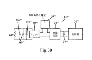
図3Aの実施例では,遠隔デバイス14’は一つの識別コンデンサ38’だけ含んでいる。図3Bの実施例では,遠隔デバイス14’’は負荷と並列に接続され,それぞれ異なる周波数の共振を与える3個の識別コンデンサ38a〜38cを備えている。類似して,所望のときは更に多くの追加共振周波数を設定するために,追加の識別コンデンサを備えてもよい。例えば図5は,4個のコンデンサの異なる組合せを用いて与えることができる共振周波数の表である。C1−C4と記された最初の4列は,4個の異なるコンデンサの容量(単位μF)を列挙している。この例では,各コンデンサは8.2μF,6.8μF,3.3μF及び2.2μFである。この表に掲げたコンデンサは単に例であって,本発明の範囲を制限するものではない。C1−C4と記された2番目の4列は,特定の組合せに含まれるコンデンサを特定するものであって,コンデンサが存在することを“1”を用いて表し,コンデンサが存在しないことを“0”で表している。「容量」と記された列は,特定の組合せに含まれるコンデンサの組合せ容量を示す。「周波数」と記された列は,最後の列に指定されるとおりインダクタンスが0.000000309のときの,各コンデンサの組合せによる共振周波数を示す。例えば,4行目はC1及びC2に“1”を含んでおり,8.2μFと6.8μFが組み合わされて3.7173μFとなり,約148.5kHzの共振周波数となる。上記2個のコンデンサの組合せ容量によって生成される共振周波数に加えて,識別コンデンサはまた,当該組合せに含まれる各コンデンサの個々の容量に対応する共振を起こす。したがって,4行目の例について続ければ,組み合わせたコンデンサはまた,約100kHz(8.2μFコンデンサの共振周波数)と,約109.9kHz(6.8μFコンデンサの共振周波数)と,に共振周波数を有する。表に示したとおり,8.2μFコンデンサと6.8μFコンデンサとの組合せは,約100kHz,約109.9kHz及び約148.5kHzの識別周波数パターンを与える。
In the embodiment of FIG. 3A, the remote device 14 'includes only one identification capacitor 38'. In the embodiment of FIG. 3B, the remote device 14 '' includes three
上述の特定の遠隔デバイスは単に例であって,本発明は本質的に,識別周波数を有し,AIPSの制限内で誘導で電力を受電できる任意の遠隔デバイスと共に用いるのによく適している。 The specific remote devices described above are merely examples, and the present invention is essentially well suited for use with any remote device that has an identification frequency and can receive power inductively within the limits of AIPS.
III. 動作
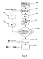
システム10の一般的動作を図6に示す。この実施例では,システム10は多数の遠隔デバイスのうち一つを認識するように構成されている。遠隔デバイスはそれぞれ,上記多数の遠隔デバイス内で一意の一つの共振周波数を含んでいる。したがってAIPS12は,選択可能な識別周波数のうち一つで共振を起こす遠隔デバイスが現れるまで,選択可能な識別周波数それぞれを巡回することによって,遠隔デバイスを一意に識別できる。
III. Operation The general operation of the
例示実施例において,AIPS12は多数の選択可能識別周波数を規定するデータを有する。例えば,選択可能な識別周波数のリスト又はテーブルは,マイクロコントローラ40のオンボードメモリに記憶してもよい。識別処理は,識別周波数をリスト内の第1周波数に設定するステップ100で始まる。そしてAIPS12は識別周波数の電力をタンク回路48に印加する。AIPS12は,遅延期間の間タンク回路48に電力を印加し続ける(ステップ104)。遅延期間は,遠隔デバイス14が共振を起こし,タンク回路48に十分な反射インピーダンスを発生させるのに十分な時間を与えるように選択される。遅延期間は,識別処理を通じて一定の固定期間であってもよい。遅延期間は応用毎に異なってもよいが,例示実施例では約6μsである。いくつかの応用では,十分な遅延はシステムに内在していることがあり,したがって別個に意図的な遅延手段を設ける必要はないことがある。遠隔デバイス14が識別周波数の共振周波数を含むときは,遠隔デバイス14は電流を発生させ,この電流発生の増加は反射インピーダンスによってタンク回路48に反映される。遅延(ステップ104)が完了した後,マイクロコントローラ40は電流検出器16からの入力を取得する(ステップ106)。上述のとおり,電流検出器16の出力は調整回路28を用いて調整してもよい。マイクロコントローラ40は,電流検出器16からの入力を評価して,遠隔デバイス14が現在の識別周波数に共振周波数を有するかどうかを判定する。この実施例では,電流検出器の示度がしきい値以上であるとき,マイクロコントローラ40は共振周波数が存在すると結論する。通常,特定応用のしきい値は当該応用のノイズフロア値と追加の不感帯の合計値以上の値である。不感帯の量は,応用毎に異なることがある。
In the exemplary embodiment,
遠隔デバイス14が現在の識別周波数に共振周波数を含まないと判定したときは,制御器20はタンク回路48に次の識別周波数を印加する準備を行う。より詳細には,マイクロコントローラ40は比較的短い遅延期間に入る(ステップ114)。この遅延期間は,遠隔デバイス14が沈静化して遠隔デバイス14内のエネルギが十分に消えるのに十分な時間を与えるように選択される。遅延時間は,識別処理を通じて一定の固定期間であってもよい。沈静化遅延時間は応用毎に異なるが,例示実施例では約5μsである。いくつかの応用では,十分な遅延がシステムに内在していることがあり,したがって別個に意図的な沈静化遅延手段を設ける必要がないことがある。この遅延の後,マイクロコントローラ40は識別周波数を選択可能な識別周波数のリストにある次の周波数に設定する。そしてこの処理は,新規識別周波数の電力をタンク回路48に印加するステップ102から繰り返す。
When the
遠隔デバイス14が現在の識別周波数に共振周波数を含むとマイクロコントローラ40が判定したとき,マイクロコントローラ40は参照テーブル24から動作パラメータを取得し(ステップ110),遠隔デバイス識別処理を終了する。そしてマイクロコントローラ40は,参照テーブル24から取得した動作パラメータを用いて遠隔デバイス14を稼動させる(ステップ112)。参照テーブル24は想定される動作周波数を含むことができ,取得した動作周波数の電力をタンク回路48に印加することによって,動作を開始できる。またマイクロコントローラ40は,参照テーブルから取得した最大最小電流発生値を用いて障害状態の存在を判定することができる。例えば,動作中に電流検出器が検出した実際の電流発生値が最大電流発生値を超えるか,最小電流発生値を下回ったとき,マイクロコントローラ40は障害状態が存在すると結論する。障害状態に遭遇したとき,救済措置をとるようにマイクロコントローラ40をプログラムしてもよい。例えば,障害状態が生じたときシステムを停止するようにマイクロコントローラ40をプログラムしてもよい。あるいは,マイクロコントローラ40は,識別処理を再開して1次コイル18のそばに別の遠隔デバイス40が置かれているかどうか判定してもよい。
When the
上述の実施例では,マイクロコントローラ40は遠隔デバイスを識別しようとして,選択可能な識別周波数のリストを巡回する。リストを巡回する代わりに,特定のステップ値を用いてある範囲の周波数を単に巡回するようにAIPS12をプログラムしてもよい。例えば,100kHzから300kHzまで5kHz刻みで実行する。
In the embodiment described above, the
別の態様において,本発明は遠隔デバイスの周波数識別を用いるための標準を確立する機構を提供する。この実施例では,遠隔デバイスの種類及び別の識別特徴毎に一意の識別周波数を指定してもよい。例えばこの標準は,デバイスの種類(例えば携帯電話機,パーソナルデジタルアシスタント,デジタル音楽再生機)毎,及び/又は製造事業者(例えば会社名)毎に異なる識別周波数を指定してもよい。製造事業者毎に一意の識別周波数が指定されている応用では,モデル番号及び製品種別を指定するために,製造事業者が付加識別周波数を追加することを許可してもよい。 In another aspect, the present invention provides a mechanism for establishing a standard for using remote device frequency identification. In this embodiment, a unique identification frequency may be specified for each type of remote device and other identification features. For example, this standard may specify a different identification frequency for each type of device (eg, mobile phone, personal digital assistant, digital music player) and / or for each manufacturer (eg, company name). In applications where a unique identification frequency is specified for each manufacturer, the manufacturer may be allowed to add additional identification frequencies to specify the model number and product type.
標準を確立する代替方法では,特定のモデル種別ではなく遠隔デバイスのクラスによって識別周波数を設定してもよい。例えば所定の動作パラメータ集合内で動作するすべてのデバイスに同一識別周波数(又は識別周波数パターン)を指定してもよい。この代替方法は,異なる種類の多数の遠隔デバイスが,参照テーブルの1レコードに設定された動作パラメータに従って動作できる応用において用いるのに特によく適している。 In an alternative method of establishing a standard, the identification frequency may be set by the remote device class rather than by a specific model type. For example, the same identification frequency (or identification frequency pattern) may be specified for all devices operating within a predetermined set of operating parameters. This alternative method is particularly well suited for use in applications where a number of different types of remote devices can operate according to the operating parameters set in one record of the lookup table.
別の実施例によれば,誘導電力供給装置によって誘導電力供給又は充電ができるデバイスに,それぞれ少なくとも一つの共通共振周波数及び少なくとも一つの一意周波数が与えられる。例えば上記実施例及び図面によれば,AIPS12によって充電できるデバイスは,それぞれ8.2μFコンデンサを備え,該コンデンサが100kHzの1次識別共振周波数をデバイスに与える。AIPS12は約100kHzのパルスを繰り返し送出する。100kHzの共振周波数を有する遠隔デバイス14がAIPS12が発生する電界内に置かれたときは,AIPSは遠隔デバイス14の種類を識別するために,追加周波数の操作に進む。一実施例によれば,個別電池種別毎の充電回路が第2一意共振周波数すなわち2次識別周波数を有する。例えばリチウムイオン電池はそれぞれ109.4kHzの2次共振周波数を与えるコンデンサ又は別の回路を含み,ニッケルカドミウム電池はそれぞれ148.5kHzの2次共振周波数を与えるコンデンサ又は別の回路を備える。別の実施例によれば,各電池は該電池の個別製造事業者又は供給事業者を識別するために用いる3次共振周波数を与えるコンデンサ又は別の回路を更に備える。例えば,ベンダXによって製造又は販売された誘導充電リチウムイオン電池はそれぞれ,100kHzの1次識別共振周波数と,109.4kHzの2次識別共振周波数と,130kHzの3次識別共振周波数と,を与える1又は複数のコンデンサ又は別の回路を備える。ベンダYによって製造又は販売されたリチウムイオン電池はそれぞれ,100kHzの1次識別共振周波数と,109.4kHzの2次識別共振周波数と,140kHzの3次識別共振周波数と,を与える1又は複数のコンデンサ又は別の回路を備える。別の実施例によれば,例えばベンダX又はベンダYによって販売された別の種類の誘導充電リチウムイオン電池を区別するために,付加識別共振周波数を追加してもよい。このような識別によってAIPSは上記の種々の負荷種別の要求条件だけでなく,それら負荷種別の個別製造事業者又は供給事業者の特定の要求条件によって,充電又は電力供給の制御を調整することができる。このような識別戦略及びプロトコルは,再充電可能電池で駆動される誘導性負荷を識別するだけでなく,直接誘導電力供給される負荷を識別するために用いることができることは明白である。
According to another embodiment, at least one common resonance frequency and at least one unique frequency are each given to devices that can be supplied or charged by the inductive power supply. For example, according to the above embodiments and drawings, each device that can be charged by the
上記の標準は,ある範囲の識別周波数の指定に依存する。識別周波数間の間隔は,識別処理の際に共振の存在を検出するAIPSの解像度に依存して,応用毎に異なってもよい。例えば5kHzの周波数差を正確に認識するのに十分な解像度を有するAIPSは,識別周波数間の分離を5kHzとしてもよい(例えば250kHzと255kHz)。低解像度のAIPSは,識別周波数間により大きな分離を必要とすることがある(例えば250kHzと260kHz)。 The above standards depend on the specification of a range of identification frequencies. The interval between identification frequencies may vary from application to application depending on the resolution of the AIPS that detects the presence of resonance during the identification process. For example, AIPS having sufficient resolution to accurately recognize a frequency difference of 5 kHz may have a separation between identification frequencies of 5 kHz (for example, 250 kHz and 255 kHz). Low resolution AIPS may require greater separation between identification frequencies (eg, 250 kHz and 260 kHz).
上記の説明は本発明の現在の実施例に関するものである。添付の請求項に規定された本発明の精神及びより広い態様から逸脱することなく,種々の代替物及び変更物を作ることができ,それらは均等論を含む特許法の原理に従って解釈されるものとする。例えば,「一つの」,「この」,又は「前記の」などを用いた単数形のどの請求要素も,該要素を単数に限定するものではない。 The above description relates to the current embodiment of the invention. Various alternatives and modifications can be made without departing from the spirit and broader aspects of the invention as defined in the appended claims, which shall be construed according to the principles of patent law, including doctrine of equivalents And For example, any claim element in the singular using "one", "this", or "above" does not limit the element to the singular.
Claims (26)
前記遠隔デバイスの2次インダクタと誘導結合を形成するように構成された誘導場発生回路と,
前記誘導場発生回路に電気的に接続され,動作周波数で前記誘導場発生回路を運転することができる周波数制御回路と,
前記遠隔デバイスの2次インダクタを介して反射された該遠隔デバイスの反射インピーダンスを示す前記誘導電力供給装置内の電力特性を検出する反射インピーダンス検出回路と,
前記反射インピーダンス検出回路の前記検出された特性によって,前記2次インダクタを介して前記遠隔デバイスの識別プロファイルを判定する識別回路であって,前記識別プロファイルは1又は複数の共振周波数を有する回路と,
1又は複数の共振周波数を含む,複数の既知遠隔デバイスの共通識別プロファイルを記憶するメモリと,
前記遠隔デバイスの前記識別プロファイルが,前記共通識別プロファイルに対応するとき,前記遠隔デバイスの前記2次インダクタに動作無線電力を供給する電源制御回路と,を備え,
前記遠隔デバイスの前記識別プロファイル及び前記動作無線電力は前記2次インダクタを介して供給される,誘導電力供給装置。An inductive power supply apparatus for supplying operating wireless power to a remote device comprising a secondary inductor configured to receive wireless power,
An induction field generating circuit configured to form inductive coupling with a secondary inductor of the remote device;
A frequency control circuit electrically connected to the induction field generating circuit and capable of operating the induction field generation circuit at an operating frequency;
A reflected impedance detection circuit for detecting a power characteristic in the inductive power supply device indicating a reflected impedance of the remote device reflected through a secondary inductor of the remote device;
An identification circuit for determining an identification profile of the remote device through the secondary inductor according to the detected characteristic of the reflection impedance detection circuit, the identification profile having a circuit having one or more resonance frequencies;
A memory storing a common identification profile of a plurality of known remote devices, including one or more resonant frequencies;
The identification profile of the remote device, can and that correspond to the common identification profile, and a power supply control circuit for supplying an operating wireless power to the secondary inductor of the remote device,
The inductive power supply apparatus , wherein the identification profile and the operating wireless power of the remote device are supplied via the secondary inductor .
前記誘導電力供給装置によって電力供給される複数の既知の遠隔デバイスの共通識別プロファイルを判定するステップであって,前記共通識別プロファイルは1又は複数の共振周波数を含む,ステップと,
前記動作無線電力を受電するように構成されたデバイス回路及び2次インダクタを備える前記遠隔デバイスを用意するステップであって,前記動作無線電力は前記デバイス回路を動作させるために用いられる,ステップと,
前記共通識別プロファイルの前記1又は複数の共振周波数で前記遠隔デバイスに誘導場を印加するステップであって,前記遠隔デバイスのインピーダンスは前記誘導場を介して前記2次インダクタから反射され,前記遠隔デバイスの共振周波数プロファイルは前記2次インダクタからの前記の反射されたインピーダンスに基づく,ステップと,
前記遠隔デバイスの前記共振周波数プロファイルが前記共通識別プロファイルに対応するかどうかを判定するステップと,
前記遠隔デバイスの前記共振周波数プロファイルが前記共通識別プロファイルに対応するとき,前記遠隔デバイスの2次インダクタに動作無線電力を供給するように前記誘導電力供給装置を運転するステップであって,前記共振周波数プロファイル及び前記動作無線電力は前記第2インダクタを介して供給される,ステップと,
を有する方法。A method of controlling an inductive power supply that supplies operating wireless power to a remote device, comprising:
Determining a common identification profile of a plurality of known remote devices powered by the inductive power supply, the common identification profile including one or more resonant frequencies;
Providing the remote device comprising a device circuit configured to receive the operating wireless power and a secondary inductor , wherein the operating wireless power is used to operate the device circuit;
Wherein in said one or more resonant frequencies of the shared identification profile comprising the steps of applying an induction field to a remote device, the impedance of the remote device is reflected from the second inductor via the induction field, the remote device The resonant frequency profile of is based on the reflected impedance from the secondary inductor , and
Determining whether the resonance frequency profile of the remote device corresponding to the common identification profile,
Wherein when the resonance frequency profile of the remote device corresponding to the common identification profile, comprising the steps of: operating the induction power supply to provide operating wireless power to the secondary inductor of the remote device, the resonant frequency A profile and the operating wireless power are supplied via the second inductor ;
Having a method.
前記誘導電力供給装置に関係するメモリに,前記一意の識別プロファイル及び関係する動作パラメータを記憶するステップと,
前記遠隔デバイスが前記共通識別プロファイルに対応する共振周波数プロファイルを有することが判定されたとき,1又は複数の前記一意の識別プロファイルに対応する1又は複数の共振周波数で,前記遠隔デバイスに誘導場を印加するステップと,
前記遠隔デバイスが前記一意の識別プロファイルのうち一つに対応する共振周波数プロファイルを有するかどうかを判定するステップと,
前記遠隔デバイスが前記一意の識別プロファイルのうち一つに対応することが判定されたとき,前記メモリから関係する動作パラメータを取得するステップと,
前記取得するステップに続いて,前記動作無線電力を前記遠隔デバイスに供給するために,前記の取得した動作パラメータに従って,前記誘導電力供給装置を運転するステップと,
を更に含む請求項10に記載の方法。Providing a unique identification profile to the remote device powered by the inductive power supply;
Storing the unique identification profile and associated operating parameters in a memory associated with the inductive power supply device;
When it is determined that the remote device has a resonant frequency profile corresponding to the common identification profile, an induction field is applied to the remote device at one or more resonant frequencies corresponding to the one or more unique identification profiles. Applying a step;
Determining whether the remote device has a resonant frequency profile corresponding to one of the unique identification profiles;
Obtaining a relevant operating parameter from the memory when it is determined that the remote device corresponds to one of the unique identification profiles;
Following the step of acquiring, operating the inductive power supply device according to the acquired operating parameter to supply the operating wireless power to the remote device;
The method of claim 10, further comprising:
デバイス回路と,動作無線電力を受電するように構成された前記2次インダクタとを有する前記遠隔デバイスを用意するステップであって,前記動作無線電力は前記デバイス回路を動作させるために用いられる,ステップと,
前記誘導電力供給装置に関係するメモリに,少なくとも一つの既知の識別プロファイルを記憶するステップと,
誘導場内に含まれる前記遠隔デバイスの識別プロファイルを判定するために,1又は複数の周波数で前記遠隔デバイスに誘導電力を印加するステップであって,前記遠隔デバイスのインピーダンスは前記遠隔デバイスに誘導電力を印加する前記ステップに応答して,前記2次インダクタから反射され,前記の判定された識別プロファイルは前記2次インダクタからの前記の反射されたインピーダンスに基づく,ステップと,
前記の判定された識別プロファイルが前記少なくとも一つの記憶された識別プロファイルの1又は複数に対応するかどうか判定するために,前記判定された識別プロファイルと前記少なくとも一つの記憶された既知の識別プロファイルとを比較するステップと,
前記判定された識別プロファイルが前記少なくとも一つの記憶された識別プロファイルの1又は複数に対応することの判定に基づいて,前記遠隔デバイスの前記2次インダクタに前記動作無線電力を供給するように前記誘導電力供給装置を運転するステップであって,前記の判定された識別プロファイル及び前記動作無線電力は前記第2インダクタを介して供給される,ステップと,
を有する方法。A method of operating an inductive power supply to provide power to a remote device comprising a secondary inductor configured to receive wireless power comprising:
Providing the remote device having a device circuit and the secondary inductor configured to receive operating wireless power, wherein the operating wireless power is used to operate the device circuit; When,
Storing at least one known identification profile in a memory associated with the inductive power supply;
Applying inductive power to the remote device at one or more frequencies to determine an identification profile of the remote device contained within an inductive field, wherein the impedance of the remote device provides inductive power to the remote device. Responsive to the step of applying, reflected from the secondary inductor , and wherein the determined identification profile is based on the reflected impedance from the secondary inductor ;
In order to determine whether the determined identification profile corresponds to one or more of the at least one stored identification profile, the determined identification profile and the at least one stored known identification profile; A step of comparing
Based on the determination that the determined identity profile corresponding to one or more of the at least one stored identification profile, the induction to supply the operation wireless power to the secondary inductor of the remote device Operating a power supply device , wherein the determined identification profile and the operating wireless power are supplied via the second inductor ;
Having a method.
前記動作パラメータは,前記識別回路によって供給される前記少なくとも一つの共振識別周波数とは異なる動作周波数を含む,請求項15に記載の方法。The remote device includes an identification circuit connected to the secondary inductor to provide at least one resonance identification frequency corresponding to at least one of the one or more frequencies of applying the inductive power. ,
The method of claim 15, wherein the operating parameter includes an operating frequency that is different from the at least one resonance identification frequency provided by the identification circuit.
前記遠隔デバイスが前記1又は複数の印加された周波数の共振周波数を有するかどうかを判定するために,前記誘導電力供給装置のタンク回路内の電流を検知するステップと,
を含む請求項18に記載の方法。The applying step comprises applying a power pulse of the one or more resonant frequencies associated with the known identification profile;
Sensing a current in a tank circuit of the inductive power supply to determine whether the remote device has a resonant frequency of the one or more applied frequencies;
The method of claim 18 comprising:
駆動器と,
1次コイルを有する1次回路と,
前記遠隔デバイスの反射インピーダンスを示す前記1次回路内の電力特性を検出するようになっている前記1次回路内の検出器であって,前記反射インピーダンスは前記遠隔デバイスの2次インダクタを介して反射される,検出器と,
前記検出器の出力によって前記遠隔デバイスの識別プロファイルを判定する識別回路であって,前記の判定された識別プロファイルは前記第2インダクタからの前記の反射されたインピーダンスに基づく,回路と,
少なくとも一つの既知の識別プロファイルを記憶するメモリと,
前記遠隔デバイスの前記の判定された識別プロファイルが少なくとも一つの既知の識別プロファイルに対応するとき,前記遠隔デバイスの2次インダクタに前記動作無線電力を供給するように,前記誘導電力供給装置の運転を制御する制御回路であって,前記の判定された識別プロファイル及び前記動作無線電力は前記第2インダクタを介して供給される,回路と,
を備える誘導電力供給装置。An inductive power supply apparatus for supplying operating wireless power to a remote device comprising a secondary inductor configured to receive wireless power comprising:
A driver,
A primary circuit having a primary coil;
A detector in the primary circuit adapted to detect a power characteristic in the primary circuit indicative of the reflected impedance of the remote device, the reflected impedance being routed through a secondary inductor of the remote device Reflected, detector,
An identification circuit for determining an identification profile of the remote device by the output of the detector, the determined identification profile being based on the reflected impedance from the second inductor ;
A memory for storing at least one known identification profile;
When the determined identification profile of the remote device corresponds to at least one known identification profile , the inductive power supply device is operated to supply the operating wireless power to a secondary inductor of the remote device. A control circuit for controlling , wherein the determined identification profile and the operating wireless power are supplied via the second inductor ;
An inductive power supply device comprising:
Applications Claiming Priority (5)
| Application Number | Priority Date | Filing Date | Title |
|---|---|---|---|
| US88312707P | 2007-01-02 | 2007-01-02 | |
| US60/883,127 | 2007-01-02 | ||
| US11/965,085 | 2007-12-27 | ||
| US11/965,085 US7989986B2 (en) | 2006-03-23 | 2007-12-27 | Inductive power supply with device identification |
| PCT/IB2007/055339 WO2008081405A1 (en) | 2007-01-02 | 2007-12-28 | Inductive power supply with device identification |
Related Child Applications (1)
| Application Number | Title | Priority Date | Filing Date |
|---|---|---|---|
| JP2012115691A Division JP5647179B2 (en) | 2007-01-02 | 2012-05-21 | Inductive power supply apparatus having device identification function |
Publications (3)
| Publication Number | Publication Date |
|---|---|
| JP2010515425A JP2010515425A (en) | 2010-05-06 |
| JP2010515425A5 JP2010515425A5 (en) | 2012-03-15 |
| JP5180228B2 true JP5180228B2 (en) | 2013-04-10 |
Family
ID=39582870
Family Applications (2)
| Application Number | Title | Priority Date | Filing Date |
|---|---|---|---|
| JP2009544472A Active JP5180228B2 (en) | 2007-01-02 | 2007-12-28 | Inductive power supply apparatus having device identification function |
| JP2012115691A Active JP5647179B2 (en) | 2007-01-02 | 2012-05-21 | Inductive power supply apparatus having device identification function |
Family Applications After (1)
| Application Number | Title | Priority Date | Filing Date |
|---|---|---|---|
| JP2012115691A Active JP5647179B2 (en) | 2007-01-02 | 2012-05-21 | Inductive power supply apparatus having device identification function |
Country Status (15)
| Country | Link |
|---|---|
| US (4) | US7989986B2 (en) |
| EP (2) | EP2118813B1 (en) |
| JP (2) | JP5180228B2 (en) |
| KR (3) | KR101731503B1 (en) |
| CN (2) | CN101622629B (en) |
| AU (1) | AU2007340951B2 (en) |
| CA (1) | CA2674103A1 (en) |
| ES (1) | ES2875973T3 (en) |
| HK (1) | HK1136371A1 (en) |
| HU (1) | HUE055217T2 (en) |
| MY (1) | MY151398A (en) |
| NZ (1) | NZ577900A (en) |
| RU (1) | RU2464632C2 (en) |
| TW (1) | TWI459678B (en) |
| WO (1) | WO2008081405A1 (en) |
Families Citing this family (144)
| Publication number | Priority date | Publication date | Assignee | Title |
|---|---|---|---|---|
| US7355150B2 (en) | 2006-03-23 | 2008-04-08 | Access Business Group International Llc | Food preparation system with inductive power |
| US7989986B2 (en) * | 2006-03-23 | 2011-08-02 | Access Business Group International Llc | Inductive power supply with device identification |
| US11245287B2 (en) | 2006-03-23 | 2022-02-08 | Philips Ip Ventures B.V. | Inductive power supply with device identification |
| MY154347A (en) * | 2007-12-21 | 2015-05-29 | Access Business Group Int Llc | Circuitry for inductive power transfer |
| EP2266179A1 (en) | 2008-03-13 | 2010-12-29 | Access Business Group International LLC | Inductive power supply system with multiple coil primary |
| JP2009268181A (en) * | 2008-04-22 | 2009-11-12 | Olympus Corp | Energy supply apparatus |
| US8981598B2 (en) | 2008-07-02 | 2015-03-17 | Powermat Technologies Ltd. | Energy efficient inductive power transmission system and method |
| US9473209B2 (en) * | 2008-08-20 | 2016-10-18 | Intel Corporation | Wireless power transfer apparatus and method thereof |
| JP4911148B2 (en) * | 2008-09-02 | 2012-04-04 | ソニー株式会社 | Contactless power supply |
| CN101667752A (en) * | 2008-09-04 | 2010-03-10 | 洪长安 | Wireless coupling resonance magneto-electric transmitter |
| TWI484716B (en) * | 2008-10-03 | 2015-05-11 | Access Business Group Int Llc | Method and apparatus for reducing poewr consumption in power system |
| JP4849190B2 (en) | 2008-11-07 | 2012-01-11 | トヨタ自動車株式会社 | Vehicle power supply system and electric vehicle |
| JP5441392B2 (en) * | 2008-11-12 | 2014-03-12 | キヤノン株式会社 | Electronic apparatus and method |
| CN102215733B (en) * | 2008-11-18 | 2014-06-18 | 奥林巴斯株式会社 | Encapsulated medical device, power supply device, and power supply system |
| US8069100B2 (en) | 2009-01-06 | 2011-11-29 | Access Business Group International Llc | Metered delivery of wireless power |
| KR20110103408A (en) * | 2009-01-08 | 2011-09-20 | 엔이씨 도낀 가부시끼가이샤 | Electric power transmitting apparatus and noncontact electric power transmission system |
| US9407327B2 (en) * | 2009-02-13 | 2016-08-02 | Qualcomm Incorporated | Wireless power for chargeable and charging devices |
| JP5533856B2 (en) * | 2009-03-30 | 2014-06-25 | 富士通株式会社 | Wireless power supply system, wireless power transmitting apparatus, and wireless power receiving apparatus |
| JP5515368B2 (en) * | 2009-03-31 | 2014-06-11 | 富士通株式会社 | Wireless power supply method and wireless power supply system |
| US8536736B2 (en) * | 2009-04-03 | 2013-09-17 | International Business Machines Corporation | Wireless power infrastructure |
| JP2010252468A (en) * | 2009-04-14 | 2010-11-04 | Sony Corp | Power transmission device and method, power receiving device and method, and power transmission system |
| US7847664B2 (en) * | 2009-05-06 | 2010-12-07 | Verde Power Supply, Inc. | Electromagnetic apparatus using shared flux in a multi-load parallel magnetic circuit and method of operation |
| US8853995B2 (en) * | 2009-06-12 | 2014-10-07 | Qualcomm Incorporated | Devices for conveying wireless power and methods of operation thereof |
| US20100327824A1 (en) * | 2009-06-30 | 2010-12-30 | Richard Dellacona | Power supply using shared flux in a multi-load parallel magnetic circuit |
| CA2768397A1 (en) * | 2009-07-24 | 2011-01-27 | Access Business Group International Llc | Power supply |
| US9312728B2 (en) * | 2009-08-24 | 2016-04-12 | Access Business Group International Llc | Physical and virtual identification in a wireless power network |
| KR101679580B1 (en) | 2009-10-16 | 2016-11-29 | 삼성전자주식회사 | Wireless Power Transmission Device, Wireless Power Transmission Controlling Device and Wireless Power Transmission Method |
| US8547057B2 (en) * | 2009-11-17 | 2013-10-01 | Qualcomm Incorporated | Systems and methods for selective wireless power transfer |
| JP2011147271A (en) * | 2010-01-14 | 2011-07-28 | Sony Corp | Power supply device, power receiving device, and wireless power supply system |
| JP5051257B2 (en) | 2010-03-16 | 2012-10-17 | トヨタ自動車株式会社 | vehicle |
| JP5691458B2 (en) * | 2010-03-31 | 2015-04-01 | 日産自動車株式会社 | Non-contact power feeding apparatus and non-contact power feeding method |
| CN103109165B (en) * | 2010-04-08 | 2015-08-19 | 捷通国际有限公司 | Point of sale induction system and method |
| JP5408343B2 (en) | 2010-04-21 | 2014-02-05 | トヨタ自動車株式会社 | Vehicle parking assist device and electric vehicle including the same |
| US20110302078A1 (en) | 2010-06-02 | 2011-12-08 | Bryan Marc Failing | Managing an energy transfer between a vehicle and an energy transfer system |
| CN102299569B (en) * | 2010-06-24 | 2014-08-13 | 海尔集团公司 | Wireless power supply system and self-adaptive adjusting method thereof |
| JP2012023913A (en) * | 2010-07-16 | 2012-02-02 | Shigeo Hamaguchi | Non-contact power feeding device |
| KR101937732B1 (en) * | 2010-07-28 | 2019-01-11 | 가부시키가이샤 한도오따이 에네루기 켄큐쇼 | Wireless power feeding system and wireless power feeding method |
| JP5538124B2 (en) * | 2010-08-03 | 2014-07-02 | 三洋電機株式会社 | Contactless charging method for battery built-in devices |
| JP5543881B2 (en) * | 2010-09-16 | 2014-07-09 | 株式会社東芝 | Wireless power transmission device |
| US9219378B2 (en) | 2010-11-01 | 2015-12-22 | Qualcomm Incorporated | Wireless charging of devices |
| RU2535951C1 (en) * | 2010-12-01 | 2014-12-20 | Тойота Дзидося Кабусики Кайся | Wireless power supply equipment, vehicle and method of controlling wireless power supply system |
| US9231412B2 (en) * | 2010-12-29 | 2016-01-05 | National Semiconductor Corporation | Resonant system for wireless power transmission to multiple receivers |
| DE102011003516A1 (en) * | 2011-02-02 | 2012-08-02 | Osram Ag | Emergency power box has semiconductor light source that is utilized for displaying usage data and for optically transmitting the usage data |
| US8946939B2 (en) * | 2011-03-31 | 2015-02-03 | Qualcomm Incorporated | Systems and methods for detecting and protecting a wireless power communication device in a wireless power system |
| US20120290470A1 (en) * | 2011-05-11 | 2012-11-15 | Samsung Electro-Mechanics Company, Ltd. | Payment systems and methods for providing wireless power transfer |
| KR102000987B1 (en) | 2011-05-17 | 2019-07-17 | 삼성전자주식회사 | Power transmitting and receiving apparatus and method for performing a wireless multi-power transmission |
| KR101241495B1 (en) * | 2011-06-08 | 2013-03-11 | 엘지이노텍 주식회사 | A wireless power transmission apparatus and method thereof |
| WO2013046209A2 (en) * | 2011-09-30 | 2013-04-04 | Powermat Technologies Ltd. | Inductive power transmission |
| KR101349551B1 (en) * | 2011-11-02 | 2014-01-08 | 엘지이노텍 주식회사 | A wireless power transmission apparatus and method thereof |
| JP5541422B2 (en) * | 2011-11-24 | 2014-07-09 | 株式会社村田製作所 | Power transmission device and power transmission control method |
| KR101254092B1 (en) * | 2011-12-21 | 2013-04-12 | 주식회사 스파콘 | Apparatus for detecting signals and wireless power transmission apparatus having the same |
| JP5894682B2 (en) * | 2011-12-29 | 2016-03-30 | アルチュリク・アノニム・シルケチ | Wireless kitchen utensils operated on induction cooker |
| US10182472B2 (en) | 2011-12-29 | 2019-01-15 | Arcelik Anonim Sirketi | Wireless kitchen appliance operated on induction heating cooker |
| US9344155B2 (en) | 2012-01-08 | 2016-05-17 | Access Business Group International Llc | Interference mitigation for multiple inductive systems |
| US9696358B2 (en) * | 2012-05-02 | 2017-07-04 | Powerbyproxi Limited | Method for detecting and identifying a receiver in an inductive power transfer system |
| KR102185160B1 (en) * | 2012-05-02 | 2020-12-02 | 애플 인크. | Methods for detecting and identifying a receiver in an inductive power transfer system |
| EP2845290B1 (en) * | 2012-05-03 | 2018-08-29 | Powermat Technologies Ltd. | System and method for triggering power transfer across an inductive power coupling and non resonant transmission |
| GB2503442A (en) | 2012-06-26 | 2014-01-01 | Ibm | Locating faults in a network |
| DE102012213363A1 (en) * | 2012-07-30 | 2014-01-30 | Siemens Aktiengesellschaft | Docking station for a wireless power and data connection |
| US9859744B2 (en) * | 2012-08-03 | 2018-01-02 | Mediatek Singapore Pte. Ltd. | Dual-mode wireless power receiver |
| US10658869B2 (en) | 2012-08-03 | 2020-05-19 | Mediatek Inc. | Multi-mode, multi-standard wireless power transmitter coil assembly |
| US9912197B2 (en) * | 2012-08-03 | 2018-03-06 | Mediatek Singapore Pte. Ltd. | Dual-mode wireless power receiver |
| US9385557B2 (en) | 2012-08-23 | 2016-07-05 | At&T Mobility Ii Llc | Methods, systems, and products for charging of devices |
| KR20210096686A (en) * | 2012-11-05 | 2021-08-05 | 애플 인크. | Inductively coupled power transfer systems |
| CN202995349U (en) * | 2012-12-26 | 2013-06-12 | 黄冠雄 | Micro-power-consumption standby system and thick film hybrid integrated circuit module |
| JP6164857B2 (en) | 2013-02-12 | 2017-07-19 | キヤノン株式会社 | Power feeding device, power feeding device control method, power receiving device, power receiving device control method, program |
| US9608513B2 (en) * | 2013-03-15 | 2017-03-28 | General Electric Company | Methods and systems for improving load transient response in LLC converters |
| EP2985874B1 (en) * | 2013-03-29 | 2017-06-14 | Nissan Motor Co., Ltd | Non-contact power supply system |
| CN104124765B (en) * | 2013-04-28 | 2018-02-16 | 海尔集团技术研发中心 | The power regulating method and system of radio energy transmission system |
| CN104124996B (en) * | 2013-04-28 | 2018-08-14 | 海尔集团技术研发中心 | Realize the method and system of radio energy transmission system wireless communication |
| US20150020615A1 (en) | 2013-07-16 | 2015-01-22 | Leeo, Inc. | Electronic device with environmental monitoring |
| US9116137B1 (en) | 2014-07-15 | 2015-08-25 | Leeo, Inc. | Selective electrical coupling based on environmental conditions |
| CN103427501B (en) * | 2013-08-19 | 2015-06-17 | 重庆大学 | Voltage-type wireless power supply system load identification method and system |
| TWI594191B (en) * | 2013-08-26 | 2017-08-01 | 緯創資通股份有限公司 | Identification system, pysical apparatus, identification apparatus, and identification method of pysical apparatus |
| US9792622B2 (en) * | 2013-09-05 | 2017-10-17 | Avago Technologies General Ip (Singapore) Pte. Ltd. | Communicating device data prior to establishing wireless power connection |
| US20150091508A1 (en) * | 2013-10-01 | 2015-04-02 | Blackberry Limited | Bi-directional communication with a device under charge |
| JP6315382B2 (en) | 2013-12-19 | 2018-04-25 | パナソニックIpマネジメント株式会社 | Power transmission device, power reception device, and wireless power transmission system for wireless power transmission |
| US20170324270A1 (en) * | 2013-12-26 | 2017-11-09 | Calvin Shie-Ning Wang | Standby circuit, and outlet, plug, and device having the same |
| US20160336807A1 (en) * | 2014-01-19 | 2016-11-17 | Powermat Technologies Ltd. | Wireless power outlet and method of transferring power thereby |
| US9995777B2 (en) * | 2014-02-14 | 2018-06-12 | Qualcomm Incorporated | Device detection through dynamic impedance change measurement |
| US9716861B1 (en) | 2014-03-07 | 2017-07-25 | Steelcase Inc. | Method and system for facilitating collaboration sessions |
| US10664772B1 (en) | 2014-03-07 | 2020-05-26 | Steelcase Inc. | Method and system for facilitating collaboration sessions |
| US9874914B2 (en) | 2014-05-19 | 2018-01-23 | Microsoft Technology Licensing, Llc | Power management contracts for accessory devices |
| US9766079B1 (en) | 2014-10-03 | 2017-09-19 | Steelcase Inc. | Method and system for locating resources and communicating within an enterprise |
| US9380682B2 (en) | 2014-06-05 | 2016-06-28 | Steelcase Inc. | Environment optimization for space based on presence and activities |
| US9955318B1 (en) | 2014-06-05 | 2018-04-24 | Steelcase Inc. | Space guidance and management system and method |
| US10614694B1 (en) | 2014-06-06 | 2020-04-07 | Steelcase Inc. | Powered furniture assembly |
| US10433646B1 (en) | 2014-06-06 | 2019-10-08 | Steelcaase Inc. | Microclimate control systems and methods |
| US11744376B2 (en) | 2014-06-06 | 2023-09-05 | Steelcase Inc. | Microclimate control systems and methods |
| US10135305B2 (en) | 2014-06-10 | 2018-11-20 | Mediatek Singapore Pte. Ltd. | Multi-mode wireless power transmitter |
| JP6381305B2 (en) * | 2014-06-10 | 2018-08-29 | キヤノン株式会社 | Electronics |
| US9717006B2 (en) | 2014-06-23 | 2017-07-25 | Microsoft Technology Licensing, Llc | Device quarantine in a wireless network |
| US9372477B2 (en) | 2014-07-15 | 2016-06-21 | Leeo, Inc. | Selective electrical coupling based on environmental conditions |
| US10305326B2 (en) * | 2014-07-16 | 2019-05-28 | Fuji Corporation | Contactless electric power supply device |
| US10218221B2 (en) | 2014-07-17 | 2019-02-26 | University Of Florida Research Foundation, Inc. | Wireless power transfer using one or more rotating magnets in a receiver |
| JP2017522992A (en) * | 2014-08-05 | 2017-08-17 | ミニパンプス, エルエルシー | Embedded telemetry using dynamic tuning |
| US9092060B1 (en) | 2014-08-27 | 2015-07-28 | Leeo, Inc. | Intuitive thermal user interface |
| US10102566B2 (en) | 2014-09-08 | 2018-10-16 | Leeo, Icnc. | Alert-driven dynamic sensor-data sub-contracting |
| US9852388B1 (en) | 2014-10-03 | 2017-12-26 | Steelcase, Inc. | Method and system for locating resources and communicating within an enterprise |
| US10026304B2 (en) | 2014-10-20 | 2018-07-17 | Leeo, Inc. | Calibrating an environmental monitoring device |
| US9445451B2 (en) | 2014-10-20 | 2016-09-13 | Leeo, Inc. | Communicating arbitrary attributes using a predefined characteristic |
| JP6213485B2 (en) * | 2014-11-28 | 2017-10-18 | トヨタ自動車株式会社 | Power transmission equipment |
| JP6013437B2 (en) * | 2014-12-05 | 2016-10-25 | 本田技研工業株式会社 | Contactless charger |
| JP2016127740A (en) * | 2015-01-06 | 2016-07-11 | 東芝テック株式会社 | Information processor and peripheral unit |
| CN104753131B (en) * | 2015-02-16 | 2016-02-24 | 郑州携能通信技术有限公司 | A kind of wireless charging method and system |
| KR102398958B1 (en) * | 2015-04-27 | 2022-05-17 | 삼성전자주식회사 | Wireless power transfer device |
| US10733371B1 (en) | 2015-06-02 | 2020-08-04 | Steelcase Inc. | Template based content preparation system for use with a plurality of space types |
| US9425644B1 (en) | 2015-06-03 | 2016-08-23 | Thor Charger Company | Method and apparatus for charging an electrically chargeable device utilizing resonating magnetic oscillations in the apparatus |
| US9801013B2 (en) | 2015-11-06 | 2017-10-24 | Leeo, Inc. | Electronic-device association based on location duration |
| US10805775B2 (en) | 2015-11-06 | 2020-10-13 | Jon Castor | Electronic-device detection and activity association |
| US11689856B2 (en) | 2015-11-19 | 2023-06-27 | The Lovesac Company | Electronic furniture systems with integrated induction charger |
| EP3709470A1 (en) | 2015-11-19 | 2020-09-16 | Apple Inc. | Inductive power transmitter |
| US10377469B2 (en) * | 2016-03-04 | 2019-08-13 | The Boeing Company | Non-contact power supply and data transfer on aerial vehicles |
| WO2017163388A1 (en) * | 2016-03-25 | 2017-09-28 | 富士機械製造株式会社 | Wireless power supply device |
| US10218212B2 (en) * | 2016-04-15 | 2019-02-26 | The Gillette Company Llc | System and apparatus for inductive charging of a handheld device |
| WO2017207304A1 (en) * | 2016-05-30 | 2017-12-07 | Philips Lighting Holding B.V. | Switched mode power supply identification |
| US9921726B1 (en) | 2016-06-03 | 2018-03-20 | Steelcase Inc. | Smart workstation method and system |
| US10128698B2 (en) * | 2016-06-20 | 2018-11-13 | Hyundai America Technical Center, Inc | Device and method for detecting an object within a wireless charging region |
| GB2565930B (en) * | 2016-06-30 | 2021-11-03 | Mitsubishi Electric Corp | Wireless power transmission system and induction heating cooker |
| US20180080999A1 (en) * | 2016-09-22 | 2018-03-22 | Qualcomm Incorporated | Determining power electronics feasibility with single turn magnetic simulation data |
| CN106487205B (en) | 2016-09-23 | 2019-01-29 | 矽力杰半导体技术(杭州)有限公司 | Parameter identification circuit, method and the power-supply system using it |
| CN107919736A (en) * | 2016-10-10 | 2018-04-17 | 三星电机株式会社 | Wireless power transmitter |
| KR101878135B1 (en) * | 2016-11-23 | 2018-07-13 | 주식회사 아프로텍 | Inductive heating apparatus having authentification of vowels |
| CN106792017B (en) * | 2016-12-09 | 2020-10-02 | 深圳Tcl数字技术有限公司 | Peripheral identification system and method and electronic equipment |
| US10264213B1 (en) | 2016-12-15 | 2019-04-16 | Steelcase Inc. | Content amplification system and method |
| KR101918229B1 (en) * | 2017-01-04 | 2018-11-13 | 엘지전자 주식회사 | Wireless charger for mobile terminal in vehicle and vehicle |
| EP3346581B1 (en) * | 2017-01-04 | 2023-06-14 | LG Electronics Inc. | Wireless charger for mobile terminal in vehicle |
| US11271429B2 (en) | 2017-03-07 | 2022-03-08 | Powermat Technologies Ltd. | System for wireless power charging |
| JP7406376B2 (en) | 2017-03-07 | 2023-12-27 | パワーマット テクノロジーズ リミテッド | System for wireless power charging |
| WO2018163177A1 (en) | 2017-03-07 | 2018-09-13 | Powermat Technologies Ltd. | System for wireless power charging |
| ES2768084T3 (en) | 2017-03-07 | 2020-06-19 | Powermat Tech Ltd | Wireless power charging system |
| WO2019051026A2 (en) * | 2017-09-06 | 2019-03-14 | Zpower, Llc | Wireless charging systems and methods |
| CN108599392B (en) * | 2018-04-26 | 2021-07-09 | 青岛众海汇智能源科技有限责任公司 | Wireless charging method and device and computer readable storage medium |
| CN110568280A (en) * | 2018-06-06 | 2019-12-13 | 上海国际汽车城(集团)有限公司 | Method for diagnosing parameter offset fault of primary side device of wireless charging system of electric automobile |
| CN109102785B (en) * | 2018-08-24 | 2020-11-13 | 北京晨语筝业教育科技有限公司 | Guzheng performance information judgment method, playing error correction method and equipment |
| US10467836B1 (en) * | 2018-11-30 | 2019-11-05 | Hans Kirchhausen | Smart storage locker for mobile devices |
| US11522619B2 (en) | 2019-03-08 | 2022-12-06 | Rovi Guides, Inc. | Frequency pairing for device synchronization |
| US11011169B2 (en) * | 2019-03-08 | 2021-05-18 | ROVl GUIDES, INC. | Inaudible frequency transmission in interactive content |
| US10956123B2 (en) | 2019-05-08 | 2021-03-23 | Rovi Guides, Inc. | Device and query management system |
| CN112394244B (en) * | 2019-08-19 | 2021-09-14 | 广东美的白色家电技术创新中心有限公司 | Detection circuit, electric appliance and control method |
| CN110474436B (en) * | 2019-08-30 | 2021-08-24 | 维沃移动通信有限公司 | Wireless charging method and related equipment |
| US11280814B2 (en) * | 2020-04-08 | 2022-03-22 | General Electic Company | Systems and methods for wearable voltage sensing devices |
| US11277024B2 (en) | 2020-07-24 | 2022-03-15 | ZQ Power, LLC | Devices, systems, and methods for reducing standby power consumption |
| AU2021325868A1 (en) | 2020-08-14 | 2023-02-16 | MTP Technologies, LLC | Cooking, soldering, and/or heating systems, and associated methods |
Family Cites Families (70)
| Publication number | Priority date | Publication date | Assignee | Title |
|---|---|---|---|---|
| US3742178A (en) * | 1971-12-29 | 1973-06-26 | Gen Electric | Induction cooking appliance including cooking vessel having means for wireless transmission of temperature data |
| US3761668A (en) * | 1972-03-01 | 1973-09-25 | Gen Electric | Small electrical apparatus powered by induction cooking appliances |
| JPS6057666B2 (en) * | 1980-01-30 | 1985-12-16 | リツカ−株式会社 | induction heating cooker |
| GB2069299B (en) * | 1980-01-30 | 1983-06-22 | Riccar Co Ltd | Induction heating apparatus |
| GB2197107B (en) | 1986-11-03 | 1990-12-12 | Mars Inc | Data-storing devices |
| FR2646049B1 (en) | 1989-04-18 | 1991-05-24 | Cableco Sa | REMOVABLE ELECTRIC HEATER PLATE |
| RU2013842C1 (en) * | 1991-07-09 | 1994-05-30 | Николай Алексеевич Шумаков | System for charging storage battery |
| JP2855929B2 (en) | 1992-01-14 | 1999-02-10 | 松下電器産業株式会社 | Cordless equipment |
| JP3198628B2 (en) | 1992-07-07 | 2001-08-13 | 松下電器産業株式会社 | Cordless equipment |
| ES2086977T3 (en) * | 1994-05-24 | 1996-07-01 | Kolja Kuse | WORKING AND COOKING IRON. |
| DE4439095A1 (en) | 1994-11-02 | 1996-05-09 | Klaus Kozitzki | Temp. regulation of cooker hob units |
| US5648008A (en) * | 1994-11-23 | 1997-07-15 | Maytag Corporation | Inductive cooking range and cooktop |
| DE19502935A1 (en) | 1995-01-31 | 1996-08-01 | Ego Elektro Blanc & Fischer | Method and device for transmitting data from a cooking vessel to a cooking device |
| AU2022797A (en) | 1996-03-15 | 1997-10-10 | Aktiebolaget Electrolux | An apparatus for providing energy to kitchen appliances |
| US5821507A (en) | 1996-04-24 | 1998-10-13 | Hidec Co., Ltd. | Electric cooker using induction heater |
| JPH10234588A (en) * | 1997-02-21 | 1998-09-08 | Haidetsuku Kk | Electromagnetic induction heater |
| JP3016732B2 (en) * | 1996-04-24 | 2000-03-06 | ハイデック株式会社 | Heat radiation heating cooker by electromagnetic induction heating |
| SG54559A1 (en) * | 1996-09-13 | 1998-11-16 | Hitachi Ltd | Power transmission system ic card and information communication system using ic card |
| JP3392016B2 (en) * | 1996-09-13 | 2003-03-31 | 株式会社日立製作所 | Power transmission system and power transmission and information communication system |
| JP3258247B2 (en) | 1996-12-09 | 2002-02-18 | 象印マホービン株式会社 | Induction heating rice cooker |
| JPH10215530A (en) | 1997-01-28 | 1998-08-11 | Matsushita Electric Works Ltd | Non-contact power transmission device |
| JPH11121159A (en) | 1997-10-20 | 1999-04-30 | Toshiba Corp | Induction heating cooker |
| AT406805B (en) | 1998-02-06 | 2000-09-25 | Bse Mediscan Ges M B H & Co Kg | METHOD FOR TREATING A GOOD |
| JP2000295796A (en) | 1999-04-02 | 2000-10-20 | Tokin Corp | Non-contact power supply |
| JP3815115B2 (en) | 1999-04-28 | 2006-08-30 | 松下電器産業株式会社 | Pan material identification instrument |
| US7212414B2 (en) * | 1999-06-21 | 2007-05-01 | Access Business Group International, Llc | Adaptive inductive power supply |
| US7522878B2 (en) * | 1999-06-21 | 2009-04-21 | Access Business Group International Llc | Adaptive inductive power supply with communication |
| US7612528B2 (en) * | 1999-06-21 | 2009-11-03 | Access Business Group International Llc | Vehicle interface |
| US6825620B2 (en) * | 1999-06-21 | 2004-11-30 | Access Business Group International Llc | Inductively coupled ballast circuit |
| US7126450B2 (en) * | 1999-06-21 | 2006-10-24 | Access Business Group International Llc | Inductively powered apparatus |
| US7518267B2 (en) * | 2003-02-04 | 2009-04-14 | Access Business Group International Llc | Power adapter for a remote device |
| US6307468B1 (en) * | 1999-07-20 | 2001-10-23 | Avid Identification Systems, Inc. | Impedance matching network and multidimensional electromagnetic field coil for a transponder interrogator |
| US6361396B1 (en) * | 1999-08-13 | 2002-03-26 | Bill Goodman Consulting, Llc | RF identification system for use in toys |
| US6364735B1 (en) * | 1999-08-13 | 2002-04-02 | Bill Goodman Consulting Llc | RF identification system for use in toys |
| US6320169B1 (en) * | 1999-09-07 | 2001-11-20 | Thermal Solutions, Inc. | Method and apparatus for magnetic induction heating using radio frequency identification of object to be heated |
| US6184651B1 (en) * | 2000-03-20 | 2001-02-06 | Motorola, Inc. | Contactless battery charger with wireless control link |
| US6484164B1 (en) * | 2000-03-29 | 2002-11-19 | Koninklijke Philips Electronics N.V. | Data search user interface with ergonomic mechanism for user profile definition and manipulation |
| MXPA02010979A (en) * | 2000-05-08 | 2003-03-27 | Checkpoint Systems Inc | Radio frequency detection and identification system. |
| DE10023179C2 (en) * | 2000-05-11 | 2002-07-18 | Schott Glas | Device and its use Control of cooktops with glass ceramic cooktops |
| JP2002075615A (en) | 2000-09-04 | 2002-03-15 | Fuji Electric Co Ltd | Electromagnetic cooker |
| DE10052689A1 (en) | 2000-10-24 | 2002-05-02 | Metronom Indvermessung Gmbh | Coding component for use in logic system associated with e.g. traffic or goods, comprises resonant circuits signaling when excited at resonant frequency |
| US6727482B2 (en) * | 2001-01-12 | 2004-04-27 | Nicholas Bassill | Apparatus and method for inductive heating |
| US6664520B2 (en) * | 2001-05-21 | 2003-12-16 | Thermal Solutions, Inc. | Thermal seat and thermal device dispensing and vending system employing RFID-based induction heating devices |
| JP4860839B2 (en) * | 2001-07-17 | 2012-01-25 | 株式会社イシダ | Box making / boxing system |
| US6957111B2 (en) * | 2001-08-24 | 2005-10-18 | Koninklijke Philips Electronics N.V. | Automated system for cooking and method of use |
| US6844702B2 (en) | 2002-05-16 | 2005-01-18 | Koninklijke Philips Electronics N.V. | System, method and apparatus for contact-less battery charging with dynamic control |
| TW200419966A (en) * | 2002-08-12 | 2004-10-01 | Mobilewise Inc | Enhanced RF wireless adaptive power provisioning system for small devices |
| WO2004027955A2 (en) | 2002-09-19 | 2004-04-01 | Quallion Llc | Battery charging system |
| US8183827B2 (en) * | 2003-01-28 | 2012-05-22 | Hewlett-Packard Development Company, L.P. | Adaptive charger system and method |
| US6953919B2 (en) * | 2003-01-30 | 2005-10-11 | Thermal Solutions, Inc. | RFID-controlled smart range and method of cooking and heating |
| EP1661436A1 (en) | 2003-08-06 | 2006-05-31 | BSH Bosch und Siemens Hausgeräte GmbH | Device for heating food using induction and device for transmitting energy |
| US6972543B1 (en) * | 2003-08-21 | 2005-12-06 | Stryker Corporation | Series resonant inductive charging circuit |
| US6943330B2 (en) * | 2003-09-25 | 2005-09-13 | 3M Innovative Properties Company | Induction heating system with resonance detection |
| JP2005143181A (en) | 2003-11-05 | 2005-06-02 | Seiko Epson Corp | Noncontact power transmitter |
| CN100541537C (en) * | 2003-11-24 | 2009-09-16 | 廖宏 | A kind of method of utilizing computing machine to the compression of digitizing files |
| US20050151511A1 (en) * | 2004-01-14 | 2005-07-14 | Intel Corporation | Transferring power between devices in a personal area network |
| DE102004003119A1 (en) | 2004-01-21 | 2005-08-11 | BSH Bosch und Siemens Hausgeräte GmbH | Device for heating food by means of inductive coupling and device for transmitting energy |
| US7573005B2 (en) * | 2004-04-22 | 2009-08-11 | Thermal Solutions, Inc. | Boil detection method and computer program |
| GB2414120B (en) * | 2004-05-11 | 2008-04-02 | Splashpower Ltd | Controlling inductive power transfer systems |
| GB2414121B (en) * | 2004-05-11 | 2008-04-02 | Splashpower Ltd | Controlling inductive power transfer systems |
| KR100564256B1 (en) | 2004-06-25 | 2006-03-29 | 주식회사 한림포스텍 | Wireless charging pad and battery pack applied radio frequency identification technology |
| JP2006060909A (en) | 2004-08-19 | 2006-03-02 | Seiko Epson Corp | Noncontact power transmitter |
| JP4302592B2 (en) | 2004-08-25 | 2009-07-29 | 三菱電機株式会社 | Induction heating cooker |
| JP2006074848A (en) | 2004-08-31 | 2006-03-16 | Hokushin Denki Kk | Non-contact power transmission system |
| US7443057B2 (en) * | 2004-11-29 | 2008-10-28 | Patrick Nunally | Remote power charging of electronic devices |
| JP2006238548A (en) * | 2005-02-23 | 2006-09-07 | Matsushita Electric Ind Co Ltd | Radio power supply unit |
| KR100903187B1 (en) * | 2005-06-25 | 2009-06-17 | 주식회사 엘지화학 | System For Identification Of Genuine Battery Product In Mobile Device |
| JP4001610B2 (en) | 2005-09-16 | 2007-10-31 | 松下電器産業株式会社 | Induction heating cooker |
| US7989986B2 (en) * | 2006-03-23 | 2011-08-02 | Access Business Group International Llc | Inductive power supply with device identification |
| US7355150B2 (en) * | 2006-03-23 | 2008-04-08 | Access Business Group International Llc | Food preparation system with inductive power |
-
2007
- 2007-12-27 US US11/965,085 patent/US7989986B2/en active Active
- 2007-12-28 KR KR1020167006193A patent/KR101731503B1/en active IP Right Grant
- 2007-12-28 EP EP07859543.6A patent/EP2118813B1/en active Active
- 2007-12-28 HU HUE19209332A patent/HUE055217T2/en unknown
- 2007-12-28 RU RU2009129485/08A patent/RU2464632C2/en active
- 2007-12-28 CN CN2007800519670A patent/CN101622629B/en active Active
- 2007-12-28 CN CN201310437765.7A patent/CN103457363B/en active Active
- 2007-12-28 AU AU2007340951A patent/AU2007340951B2/en not_active Ceased
- 2007-12-28 EP EP19209332.6A patent/EP3640836B1/en active Active
- 2007-12-28 MY MYPI20092658 patent/MY151398A/en unknown
- 2007-12-28 KR KR1020157006924A patent/KR101603275B1/en active Application Filing
- 2007-12-28 KR KR1020177011064A patent/KR101842611B1/en active IP Right Grant
- 2007-12-28 ES ES19209332T patent/ES2875973T3/en active Active
- 2007-12-28 NZ NZ577900A patent/NZ577900A/en not_active IP Right Cessation
- 2007-12-28 CA CA002674103A patent/CA2674103A1/en not_active Abandoned
- 2007-12-28 JP JP2009544472A patent/JP5180228B2/en active Active
- 2007-12-28 WO PCT/IB2007/055339 patent/WO2008081405A1/en active Application Filing
- 2007-12-31 TW TW096151368A patent/TWI459678B/en active
-
2010
- 2010-03-16 HK HK10102767.5A patent/HK1136371A1/en unknown
-
2011
- 2011-06-22 US US13/166,187 patent/US8097984B2/en active Active
- 2011-12-12 US US13/323,126 patent/US9318912B2/en active Active
-
2012
- 2012-05-21 JP JP2012115691A patent/JP5647179B2/en active Active
-
2016
- 2016-03-03 US US15/059,344 patent/US10305329B2/en active Active
Also Published As
Similar Documents
| Publication | Publication Date | Title |
|---|---|---|
| JP5180228B2 (en) | Inductive power supply apparatus having device identification function | |
| TWI710196B (en) | Methods and apparatus of performing foreign object detecting | |
| AU2016241101B2 (en) | Inductive power transmitter | |
| EP3306781A1 (en) | Wireless power transmission system and method for driving same | |
| CN102017356A (en) | Inductive power supply system with battery type detection | |
| KR101536367B1 (en) | Inductive power supply with device identification | |
| US11245287B2 (en) | Inductive power supply with device identification | |
| JP6736704B2 (en) | Method for detecting receiver and inductive power transfer system | |
| CN110391697B (en) | Method and apparatus for performing foreign matter detection |
Legal Events
| Date | Code | Title | Description |
|---|---|---|---|
| A621 | Written request for application examination |
Free format text: JAPANESE INTERMEDIATE CODE: A621 Effective date: 20101101 |
|
| A521 | Request for written amendment filed |
Free format text: JAPANESE INTERMEDIATE CODE: A523 Effective date: 20120127 |
|
| A871 | Explanation of circumstances concerning accelerated examination |
Free format text: JAPANESE INTERMEDIATE CODE: A871 Effective date: 20120127 |
|
| A975 | Report on accelerated examination |
Free format text: JAPANESE INTERMEDIATE CODE: A971005 Effective date: 20120210 |
|
| A131 | Notification of reasons for refusal |
Free format text: JAPANESE INTERMEDIATE CODE: A131 Effective date: 20120221 |
|
| A521 | Request for written amendment filed |
Free format text: JAPANESE INTERMEDIATE CODE: A523 Effective date: 20120521 |
|
| A131 | Notification of reasons for refusal |
Free format text: JAPANESE INTERMEDIATE CODE: A131 Effective date: 20120626 |
|
| A521 | Request for written amendment filed |
Free format text: JAPANESE INTERMEDIATE CODE: A523 Effective date: 20120924 |
|
| TRDD | Decision of grant or rejection written | ||
| A01 | Written decision to grant a patent or to grant a registration (utility model) |
Free format text: JAPANESE INTERMEDIATE CODE: A01 Effective date: 20121211 |
|
| A61 | First payment of annual fees (during grant procedure) |
Free format text: JAPANESE INTERMEDIATE CODE: A61 Effective date: 20130110 |
|
| R150 | Certificate of patent or registration of utility model |
Ref document number: 5180228 Country of ref document: JP Free format text: JAPANESE INTERMEDIATE CODE: R150 |
|
| R250 | Receipt of annual fees |
Free format text: JAPANESE INTERMEDIATE CODE: R250 |
|
| R250 | Receipt of annual fees |
Free format text: JAPANESE INTERMEDIATE CODE: R250 |
|
| R250 | Receipt of annual fees |
Free format text: JAPANESE INTERMEDIATE CODE: R250 |
|
| S111 | Request for change of ownership or part of ownership |
Free format text: JAPANESE INTERMEDIATE CODE: R313113 |
|
| R350 | Written notification of registration of transfer |
Free format text: JAPANESE INTERMEDIATE CODE: R350 |
|
| R250 | Receipt of annual fees |
Free format text: JAPANESE INTERMEDIATE CODE: R250 |
|
| R250 | Receipt of annual fees |
Free format text: JAPANESE INTERMEDIATE CODE: R250 |
|
| R250 | Receipt of annual fees |
Free format text: JAPANESE INTERMEDIATE CODE: R250 |
|
| R250 | Receipt of annual fees |
Free format text: JAPANESE INTERMEDIATE CODE: R250 |
|
| R250 | Receipt of annual fees |
Free format text: JAPANESE INTERMEDIATE CODE: R250 |
|
| S531 | Written request for registration of change of domicile |
Free format text: JAPANESE INTERMEDIATE CODE: R313531 |
|
| R350 | Written notification of registration of transfer |
Free format text: JAPANESE INTERMEDIATE CODE: R350 |
|
| R250 | Receipt of annual fees |
Free format text: JAPANESE INTERMEDIATE CODE: R250 |