JP5173957B2 - Air conditioner indoor unit - Google Patents
Air conditioner indoor unit Download PDFInfo
- Publication number
- JP5173957B2 JP5173957B2 JP2009176219A JP2009176219A JP5173957B2 JP 5173957 B2 JP5173957 B2 JP 5173957B2 JP 2009176219 A JP2009176219 A JP 2009176219A JP 2009176219 A JP2009176219 A JP 2009176219A JP 5173957 B2 JP5173957 B2 JP 5173957B2
- Authority
- JP
- Japan
- Prior art keywords
- holder
- window
- case
- indoor unit
- sensor
- Prior art date
- Legal status (The legal status is an assumption and is not a legal conclusion. Google has not performed a legal analysis and makes no representation as to the accuracy of the status listed.)
- Expired - Fee Related
Links
Images


Description
本発明は空気調和機の室内機、特に、可動式の赤外線センサーと、運転状況を表示する表示手段とを装備した、空気調和機の室内機に関するものである。 The present invention relates to an indoor unit of an air conditioner, and more particularly to an indoor unit of an air conditioner equipped with a movable infrared sensor and a display means for displaying an operation status.
従来、可動式の赤外線センサーを搭載した空気調和機の室内機(以下、単に「室内機」と称す)として、センサーの向きが明確に分かるよう、回動自在なセンサーケースに赤外線センサーおよび方向指示用の発光素子(LED等)を設置し、センサーケースを覆う半透明のカバーを設けた発明が開示されている(例えば、特許文献1参照)。
一方、運転状況を表示する表示手段を装備した室内機として、運転状況を確実に、且つ目立ち過ぎないように表示するため、前面意匠パネルに溝状の開口部(スリット)を設け、当該スリットの後方に光透過性半透明材料からなる略プリズム状の帯状部材を配置すると共に、当該帯状部材の下面に、運転モードに応じて色や発光位置が変化する光を発するLEDを配置して、帯状部材の前面から光を出射する発明が開示されている(例えば、特許文献2参照)。
Conventionally, as an indoor unit of an air conditioner equipped with a movable infrared sensor (hereinafter simply referred to as “indoor unit”), an infrared sensor and direction indication are provided on a rotatable sensor case so that the direction of the sensor can be clearly seen. An invention is disclosed in which a light-emitting element (such as an LED) is installed and a translucent cover that covers a sensor case is provided (see, for example, Patent Document 1).
On the other hand, as an indoor unit equipped with a display means for displaying the operation status, a groove-shaped opening (slit) is provided on the front design panel in order to display the operation status reliably and without being noticeable. A substantially prism-shaped belt-shaped member made of a light-transmitting translucent material is disposed behind, and an LED that emits light whose color or light emission position changes according to the operation mode is disposed on the lower surface of the belt-shaped member. An invention for emitting light from the front surface of a member is disclosed (for example, see Patent Document 2).
特許文献1に開示された室内機は、センサーケースが室内機本体の内部に収納されて半透明のカバーに覆われているため、赤外線センサーの向きが分かり難いという問題、また、赤外線センサーの受信範囲を広くしようとするとカバーが拡大することから、室内機の前面の意匠性が阻害されるという問題があった。
一方、特許文献2に開示された室内機は、前面意匠パネルの左右方向の広い範囲に溝状の開口部(スリット)が設けられるため、室内機の前面の意匠性が阻害されるという問題があった。また、LEDを実装した基板が左右方向で長くなり、機器配置の自由度が小さくなっていた。
The indoor unit disclosed in
On the other hand, the indoor unit disclosed in
さらに、可動式の赤外線センサーと運転状況を表示する表示手段との両方を装備した室内機を得ようとして、特許文献1に開示された室内機と特許文献2に開示された室内機とを組み合わせたのでは、それぞれが別個の位置に配置されるため、室内機の前面の意匠性が阻害されるという問題があった。また、操作者の視線が分散されるため、操作性や視認性が悪化するという問題があった。
また、両者を同一位置に配置しようとすると、略プリズム状の帯状部材が赤外線センサーの受信範囲(半透明のカバー)と干渉しないように、たとえば、帯状部材を二分割して、それぞれがセンサーケースを挟むように左右に離して配置することになり、室内機の前面の意匠性が阻害されるという問題があった。
Furthermore, the indoor unit disclosed in
Also, for example, when the two members are arranged at the same position, the belt-shaped member is divided into two parts so that the substantially prism-shaped belt-shaped member does not interfere with the receiving range (semi-transparent cover) of the infrared sensor. Therefore, there is a problem that the design of the front surface of the indoor unit is hindered.
本発明は、上記のような課題を解決するためになされたもので、可動式の赤外線センサーと運転状況を表示する表示手段との両方を装備しながら、赤外線センサーの向きが分かり易く、意匠性に優れた室内機を得ることにある。 The present invention has been made in order to solve the above-described problems, and is equipped with both a movable infrared sensor and a display means for displaying the operation status, and the orientation of the infrared sensor is easy to understand and has a design property. It is to obtain an excellent indoor unit.
本発明に係る空気調和機の室内機は、
吸引口および吹出口、並びに前面に前面開口部を具備する室内機本体と、
前記吸引口から前記吹出口に至る風路を形成する送風手段と、
前記風路内に配置された熱交換手段と、
前記室内機本体の前面開口部を覆い且つ開放すると共に、開口部であるパネル窓が形成された前面意匠パネルと、
前記室内機本体の前面開口部に設置されたセンサーユニットと、
を有し、
前記センサーユニットが、赤外線センサーと、
該赤外線センサーを収納し、前記赤外線センサーの受信範囲に相当した開口部であるケース窓を具備する光不透過材または光難透過材によって形成されたセンサーケースと、
前記室内機本体に設置され、前記センサーケースを回動自在に保持すると共に、前記赤外線センサーが回動した際の受信範囲に相当した開口部であるホルダー窓を具備する光透過材によって形成されたケースホルダーと、
該ケースホルダーに設置され、前記センサーケースを回動するモーターと、
前記室内機本体に設置され、前記ケースホルダーの前面の略全域を覆うと共に、前記ケースホルダーのホルダー窓の周縁が侵入自在な開口部である前カバー窓を具備する光不透過材または光難透過材によって形成されたホルダー前カバーと、
前記ケースホルダーに向かって光を照射する発光手段と、
を有し、
前記前面意匠パネルが前記室内機本体の前面開口部を覆った際、前記パネル窓の内側に前記ホルダー窓の周縁が位置することによって、前記発光手段が照射した光の一部が、前記ケースホルダーに入射した後、前記ホルダー窓の周縁から出射されることを特徴とする。
The indoor unit of the air conditioner according to the present invention is
An indoor unit body having a suction port and a blowout port, and a front opening on the front surface;
A blowing means for forming an air passage from the suction port to the blowout port;
Heat exchange means disposed in the air path;
Covering and opening the front opening of the indoor unit main body, and a front design panel in which a panel window as an opening is formed,
A sensor unit installed in the front opening of the indoor unit body;
Have
The sensor unit is an infrared sensor;
A sensor case formed of a light-impermeable material or a light-impermeable material, which houses the infrared sensor and includes a case window that is an opening corresponding to a reception range of the infrared sensor;
It is installed in the indoor unit main body and is formed by a light transmitting material having a holder window that is an opening corresponding to a receiving range when the infrared sensor rotates while holding the sensor case rotatably. A case holder,
A motor installed in the case holder and rotating the sensor case;
A light-impermeable material or a light-impermeable material, which is installed in the indoor unit main body and covers a substantially entire front surface of the case holder and has a front cover window which is an opening through which a peripheral edge of the holder window of the case holder can freely enter. A holder front cover made of material,
A light emitting means for irradiating light toward the case holder;
Have
When the front design panel covers the front opening of the indoor unit main body, the periphery of the holder window is positioned inside the panel window, so that a part of the light emitted by the light emitting means is part of the case holder. Then, the light is emitted from the periphery of the holder window.
本発明に係る空気調和機の室内機は、前記構成であるから、前面意匠パネルが前面開口部を覆った際、操作者(室内にいる人間)は正面から、パネル窓の内側にケースホルダーのホルダー窓の周縁を視認することができる。このとき、ホルダー窓の内側にはセンサーケースのケース窓が位置し、ケース窓を透過して赤外線センサーを視認することができるから、赤外線センサーの向きを正確に、且つ容易に知ることができる。
また、ケースホルダーの後面側に発光手段が配置されるから、発光手段が光を照射すると、ケースホルダーに入射した光の一部はホルダー窓の周縁から出射する。このとき、ホルダー窓の周縁の外側は光不透過性のホルダー前カバーによって覆われ、ホルダー窓の内側には光不透過性のセンサーケースの外面が位置しているから、発光手段が発した光はホルダー窓の周縁からのみ室内側に出射される。
すなわち、ホルダー窓の周縁を形成する所定幅の略円弧状(略U字状)や環状に光が視認されるから、室内機の意匠性が向上する。
さらに、運転状況の表示部と赤外線センサーとが同一位置にあるから、操作性や視認性が悪化することがない。
Since the indoor unit of the air conditioner according to the present invention has the above-described configuration, when the front design panel covers the front opening, the operator (the person in the room) has the case holder inside the panel window from the front. The periphery of the holder window can be visually recognized. At this time, the case window of the sensor case is located inside the holder window, and the infrared sensor can be seen through the case window, so that the direction of the infrared sensor can be accurately and easily known.
Further, since the light emitting means is disposed on the rear surface side of the case holder, when the light emitting means emits light, a part of the light incident on the case holder is emitted from the periphery of the holder window. At this time, the outer periphery of the holder window is covered with a light-impermeable holder front cover, and the outer surface of the light-impermeable sensor case is located inside the holder window. Is emitted indoors only from the periphery of the holder window.
That is, since the light is visually recognized in a substantially arc shape (substantially U shape) or an annular shape having a predetermined width that forms the periphery of the holder window, the design of the indoor unit is improved.
Furthermore, since the display part of a driving condition and an infrared sensor are in the same position, operativity and visibility do not deteriorate.
[実施の形態1]
(空気調和機の室内機)
図1〜図3は本発明の実施の形態1に係る空気調和機の室内機を説明するものであって、図1は正面図、図2は構成部材を分解して示す斜視図、図3は側面視の断面図である。
なお、以下に示す各図において同じ部分または相当する部分には同じ符号を付している。また、各図は模式的に描いたものであって、本発明は図示された形態に限定するものではない。
図1〜図3において、空気調和機の室内機(以下「室内機」と称す)10は、吸引口10aおよび吹出口10cを具備する室内機本体3と、吸引口10aから吹出口10cに至る風路10bを形成する送風手段7と、風路10b内に配置された熱交換手段6と、を有している。
[Embodiment 1]
(Air conditioner indoor unit)
1 to 3 illustrate an indoor unit of an air conditioner according to
In addition, in each figure shown below, the same code | symbol is attached | subjected to the same part or an equivalent part. Each figure is drawn typically and the present invention is not limited to the illustrated form.
1 to 3, an indoor unit (hereinafter referred to as “indoor unit”) 10 of an air conditioner reaches an
(室内機本体)
室内機本体3は室内の壁等に固定される基台9(以下、基台9側を「後面」と称す)と、基台9に固定される筐体2とを有している。そして、筐体2の前面傾向部を覆う前面意匠パネル1が、筐体2の前面寄り(室内機本体3の前面に同じ)に着脱自在かつ回動自在に設置されている。
筐体2の上面には吸引口10aが形成され、筐体2の下面(上面の一部を含む)には吹出口10cが形成され、基台9の一部が風路10bの一部(後面側)を形成している。また、吹出口10cには、前面上下風向ベーン301と下面上下風向ベーン302とを具備する上下風向調整装置300が設置されている。
(Indoor unit body)
The indoor unit
A
送風手段7は基台9に装着されるものであって、風路10bを形成している。
熱交換手段6は基台9に装着されるものであって、後面側部分および前面側部分とを具備し、風路10bの送風手段7よりも上流側に配置され、図示しない室外機から供給される冷媒が流通する伝熱管6aと、伝熱管6aが貫通する複数枚の放熱フィン6bとを具備している。
そして、熱交換手段6の前面側部分の下方には、熱交換手段6から滴下したドレンを受け止めるドレンパン5が、基台9に装着されている。なお、ドレンパン5の下面は風路10bの一部を形成するものであって、図示しない左右風向調整装置が設置されている。
さらに、風路10bの吸引口10aの近くで前面寄りに、フィルター4aを清掃するためのフィルター自動清掃ユニット4が着脱自在かつ移動自在に設置(基台9に爪によって、熱交換手段6にネジによってそれぞれ固定)されている。そして、前面開口部の上下方向の略中央に、フィルター4aから落下した塵埃を貯溜するためのダストボックス4bが設置されている。
The air blowing means 7 is attached to the base 9 and forms an
The
A
Further, an automatic
(表示装置)
前面意匠パネル1は、透明樹脂材料で成形され裏面に塗装または印刷などで光の透過が可能な色で着色された意匠層が形成されている。また、ダストボックス4bの前面側で、室内機本体3の左右方向の略中央に表示装置100が配置されている(ドレンパン5とフィルター自動清掃ユニット4とに固定されている)。
したがって、前面意匠パネル1が前面開口部を覆った際、前面意匠パネル1とダストボックス4bとによって表示装置100は、あたかも挟まれた状態になる。すなわち、表示装置100の前面には、表示内容を印刷した印刷シート13が貼付されているから、印刷シート13が前面意匠パネル1の後面に押し付けられる(これについては別途詳細に説明する)。
そうすると、表示内容が前面意匠パネル1の裏面に鮮明に投影される。したがって、投影された表示内容は、透光性材料によって形成された前面意匠パネル1を透過して、前面意匠パネル1の前面に表示範囲1cとして表示される。すなわち、表示内容を室内機10の外部から視認することができる。
(Display device)
The
Therefore, when the
Then, the display content is clearly projected on the back surface of the
(表示装置の構成)
次に、表示装置について詳細に説明する。
図4は本発明の実施の形態1に係る空気調和機の室内機に設置された表示装置を説明するものであって、構成部材を分解して示す斜視図である。
図4において、表示装置100は、枠状の表示装置カバー12と、表示内容が印刷された印刷シート13と、印刷シート13が前面に貼付された基板ホルダー14と、基板ホルダー14にネジ止めされる基板15と、板状の表示装置ベース16と、を有している。
(Configuration of display device)
Next, the display device will be described in detail.
FIG. 4 is a perspective view for explaining the display device installed in the indoor unit of the air conditioner according to
In FIG. 4, the
表示装置カバー12は表示装置ベース16に取り付けられ、両者によって開口部を具備する函体が形成され、該函体内に基板ホルダー14が収納される。そして、基板ホルダー14は付勢手段(たとえば、コイルスプリング)19によって前面方向に付勢されるから、基板ホルダー14の前面(印刷シート13が貼付されている)は、函体から前面方向に押し出される。
また、前面意匠パネル1は光透過材料によって形成され、印刷シート13には数字、記号、イラスト等の輪郭が縁取り印刷されているから、前面意匠パネル1が前面開口部を塞いだ際、基板15に実装された発光手段(LED等)からの光によって、印刷シート13に印刷された数字等が、前面意匠パネル1に投影されることになる。
The
Further, the
表示装置ベース16には、上方に突出するベースアーム16aが設けられ、ベースアーム16aの先端には、回動用のベース回動軸16bが形成されている。
一方、筐体2に固定された表示装置取付体18には、ベース回動軸16bが侵入自在な取付体切欠部18bが形成され、また、表示装置取付体18に取り付けられる回動軸受部材17にも、ベース回動軸16bが侵入自在な軸受部材切欠部17bが形成されている。
そして、取付体切欠部18bと軸受部材切欠部17bとによって形成される略円筒状の回動軸受に、ベース回動軸16bが回動自在に支持される。
なお、運転制御のためのセンサーユニット200が表示装置100の下方に配置されて、表示装置取付体18は、センサーユニット200の取付体も兼ねている。
The
On the other hand, the display
The
In addition, the
(センサーユニット)
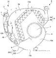
図5〜図14は本発明の実施の形態1に係る空気調和機の室内機に設置されたセンサーユニットを説明するものであって、図5は構成部材を分解して示す斜視図、図6は構成部材の一部を示す側面視の断面図、図7は室内機本体への取付要領を説明する斜視図、図8は組立途中の状態を示す側面視の断面図、図9は組立途中の状態を示す正面図、図10は組立後の状態を示す側面視の断面図、図11は組立後の状態を示す正面図、図12は室内機に設置された状態を示す側面視の断面図、図13は図12に示す状態の平面視の部分断面図、図14は図12に示す状態の部分正面図である。
(Sensor unit)
5 to 14 illustrate the sensor unit installed in the indoor unit of the air conditioner according to
センサーユニット200は、赤外線センサー20と、赤外線センサー20を収納し、赤外線センサー20の受信範囲に相当した開口部であるケース窓30aを具備する光不透過材または光難透過材によって形成されたセンサーケース30と、を有している。そして、センサーケース30は、室内機本体3(正確には、筐体2に取り付けられた表示装置取付体18)に設置されたケースホルダー40に回動自在に保持されている。
The
ケースホルダー40は光透過材によって形成され、赤外線センサー20が回動した際の受信範囲に相当した開口部であるホルダー窓40aを具備している。
ケースホルダー40にはセンサーケース30を回動するモーター50が設置される。
さらに、ケースホルダー40の前面の略全域を覆うと共に、ケースホルダー40のホルダー窓40aのホルダー窓周縁40bが侵入自在な開口部である前カバー窓60aを具備する、光不透過材または光難透過材によって形成されたホルダー前カバー60が、室内機本体3(正確には、筐体2に取り付けられた表示装置取付体18)に設置されている。
さらに、ケースホルダー40の後面に向かって光を照射する発光手段70が、室内機本体3(正確には、筐体2に取り付けられた表示装置取付体18)に設置されている。
The
The
Further, the
Furthermore, the light emitting means 70 for irradiating light toward the rear surface of the
(赤外線センサー)
赤外線センサー20は、室内の温度分布を測定するものであって、モーター50の回転角度との関係において室内に居る人間の位置を判定することができるものである。したがって、室内機10は、かかる判定に基づいて、吹き出す空気の温度や、吹き出し方向等を制御することが可能になっている。
(Infrared sensor)
The
(センサーケース)
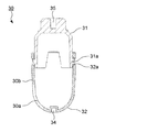
センサーケース30は、上部を構成するモーター連結部(ケース上部に同じ)31と、下部を構成するセンサーカバー部(ケース下部に同じ)32とが、一体になった略繭型(上限端部が略半球状の筒体)である。すなわち、モーター連結部31に形成されたケース爪31aが、センサーカバー部32に形成されたケース孔32aに係合している(図6参照)。なお、モーター連結部31にケース孔を形成し、センサーカバー部32にケース爪を形成してもよい。
モーター連結部31の頂点(北極点)にはモーター50のモーター回転軸51が嵌合するケース上部軸受35が形成されている。また、センサーカバー部32には開口したケース窓30aが形成されると共に、下端(南極点)には、ケースホルダー40に設けられたホルダー軸44が侵入するケース下部軸受34が形成されている。
(Sensor case)
The
A case
(ケースホルダー)
ケースホルダー40は、センサーケース30を収納する略半円筒のホルダー筒部41と、ホルダー筒部41の側面に対向して設けられたホルダー側板42と、ホルダー筒部41の上端部に設けられたホルダー上板43と、を有している。
ホルダー筒部41には開口するホルダー窓40aが形成されると共に、ホルダー筒部41の底にはホルダー軸44が設けられている。
図7において、センサーユニット200は表示装置取付体18(筐体2に固定されている)に設置される。すなわち、ケースホルダー40のホルダー側板42が、表示装置取付体18に設けられたホルダー設置部18aに当接(陥入)し、ホルダー側板42に形成された係合爪(図示しない)がホルダー設置部18aに形成された係合孔(図示しない)に係合する。
(Case holder)
The
A
In FIG. 7, the
(ホルダー前カバー)
ケースホルダー40を覆い隠すように、ホルダー前カバー60が表示装置取付体18に設置される。ホルダー前カバー60は正面視で略逆T字状であって、ホルダー筒部41およびホルダー上板43を覆うと共に、上方に延長した前カバー上板部61と、ホルダー側板42を覆う前カバー側板部とを有している。そして、前カバー上板部61および前カバー側板部62に形成された係合爪(図示しない)がホルダー設置部18aに形成された係合孔(図示しない)に係合する。
なお、ホルダー前カバー60には、ケースホルダー40のホルダー筒部41の一部(ホルダー窓40aのホルダー窓周縁40b)が侵入自在な前カバー窓60aが形成されている。
(Holder front cover)
A
The
(組立状態)
図8において、ケースホルダー40のホルダー側板42が表示装置取付体18(図示しない)に設置されている。
そして、モーター50は、モーター回転軸51がケースホルダー40のホルダー筒部41に挿入された状態で、ホルダー上板43にモーター固体ネジ52によって固定されている。また、ホルダー筒部41の内部にはセンサーケース30が収納され、赤外線センサー20の受信面がケース窓30aに一致した姿勢で固定されている。
また、ケース上部軸受35にモーター回転軸51が陥入(相対的な回転が不能に侵入しているに同じ)し、ケース下部軸受34にケースホルダー40のホルダー軸44が侵入しているから、センサーケース30(赤外線センサー20に同じ)は、モーター50の回転によって、左右方向の所定の角度を往復する回転(揺動)をすることができる。
このとき、センサーケース30は回転軸が変動しないように保持された状態で、回動するから、センサーケース30の外面とホルダー筒部41の内面との隙間を狭くすることが可能になる。
(Assembled state)
In FIG. 8, the
The
Further, since the
At this time, since the
図9に示す正面図において、便宜上、ケースホルダー40に右下がりの斜線を付している。すなわち、センサーケース30の前面は殆どの範囲がケースホルダー40によって覆われ、センサーカバー部(ケース下部に同じ)32のケース窓30aを含む範囲が、ホルダー窓40aから視認可能になっている。このとき、ホルダー窓40aは正面視で左右方向に拡がった楕円形状であるため、センサーケース30が左右方向の所定の角度を往復する回転(揺動)をしても、赤外線センサー20の受信範囲にホルダー窓40aが干渉することがない。
また、ホルダー窓40aを通して、センサーケース30のケース窓30aの方向を視認することができるから、確実且つ容易に、赤外線センサー20の方向(受信方向)を知ることができる。
In the front view shown in FIG. 9, for convenience, the
Further, since the direction of the
図10および図11において、ホルダー前カバー60(便宜上、ホルダー前カバー60に左下がりの斜線を付している)が表示装置取付体18に設置されている。このため、ケースホルダー40のホルダー筒部41の一部(ホルダー窓40aのホルダー窓周縁40b)が前カバー窓60aに侵入し、前面方向に突出し、ホルダー窓40aのホルダー窓周縁40bを除く範囲がホルダー前カバー60によって覆われている。
すなわち、ホルダー窓40aのホルダー窓周縁40bとホルダー窓40aの範囲に位置するセンサーケース30の一部(ケース窓30aのケース窓周縁30b)のみが、正面から視認可能になっている。
10 and 11, the holder front cover 60 (for convenience, the
That is, only the
図12〜図14において、前面意匠パネル1が前面開口部を塞いでいる。このとき、前面意匠パネル1に形成された貫通孔であるパネル窓1aと、ケースホルダー40のホルダー窓40aの位置が一致している。すなわち、ホルダー窓40aのホルダー窓周縁40bを除く広い範囲が前面意匠パネル1によって覆われ、当然に、ホルダー前カバー60の全域が前面意匠パネル1によって覆われている。
また、パネル窓1aの左右には、パネル窓1aに近づく程、後退する(後面側に位置する)パネル斜面1bが形成されている。したがって、センサーケース30が左右方向に回動しても、赤外線センサー20の受信範囲に前面意匠パネル1の一部が干渉することがない(図1参照)。
12 to 14, the
In addition, panel slopes 1b are formed on the left and right sides of the
(発光手段)
そして、ケースホルダー40の後方(後面寄り)には、発光手段70が表示装置取付体18に設置されている。発光手段70には、三色LED70aが実装されて、運転モードに応じた所定の色の光を、照射(点灯および点滅を含む)することができる。
そして、三色LED70aが発光すると、発せられた光がケースホルダー40を照射する。ケースホルダー40は透明もしくは半透明樹脂で、光透過性を有する材料で成形されているため、三色LED70aから照射された光は透過する(一方から入射した光は内部を通過して他方から出射する)。
また、前面意匠パネル1が前面開口部を塞さいだ状態では、ケースホルダー40のホルダー窓40aのホルダー窓周縁40bおよびホルダー窓40aの内側のセンサーケース30の外面(ケース窓30aのケース窓周縁30bを含む)が、パネル窓1aから視認可能である。しかしながら、センサーケース30は光不透過性または光難透過性を有する材料で形成され、ケースホルダー40のホルダー窓40aのホルダー窓周縁40bを除く範囲は、光不透過性または光難透過性を有する材料で形成されたホルダー前カバー60によって覆われている。
(Light emission means)
The light emitting means 70 is installed on the display
When the three-
When the
このため、三色LED70aから照射された光は、ホルダー窓40aのホルダー窓周縁40b(内周を形成する端面を含む)から出射される一部の光のみ、正面から視認することができる。すなわち、パネル窓1aからはケースホルダー40のホルダー窓40aのホルダー窓周縁40bのみが見えるため、センサーケース30の外周に沿ってのみ、発光しているよう視認される。このとき、ケースホルダー40の露出したホルダー窓周縁40b以外からは光が室内機10の外に出射されないから、略U字状また略三角形の環状に赤外線センサー20の周囲を光らせることができる。
さらに、センサーケース30は回転軸が変動しないように保持された状態で、回動するため、センサーケース30の外面とホルダー筒部41の内面との隙間を狭くすることが可能になるから、ホルダー窓40aの内側に視認されるセンサーケース30の一部とホルダー筒部41の一部とを近接させることが可能になり、意匠性が向上している。
For this reason, only a part of the light emitted from the three-
Furthermore, since the
一方、従来技術のようにケースホルダー40を設置しない場合には、前記のような、略U字状または環状の発光範囲が得られないだけでなく、前面意匠パネル1に摺動することなく、センサーケース30を回動させるためには、前面意匠パネル1の開閉時のズレを考慮して、パネル窓1aの内周とセンサーケース30の外周との隙間を大きくする必要があった。このため、当該隙間は物体の無い範囲あるいは暗い範囲として、前面意匠パネル1に不要に大きな欠損が形成されているように視認され、意匠性を阻害していた。
On the other hand, when the
さらに、室内機10では、パネル窓1aにケースホルダー40のホルダー窓40aのホルダー窓周縁40bが侵入し、ホルダー窓40aにはセンサーケース30のケース窓30aのケース窓周縁30bが位置し、ホルダー窓40aのホルダー窓周縁40bは発光している(光を出射している)。
したがって、パネル窓1aの内縁とホルダー窓40aのホルダー窓周縁40bとの隙間、およびホルダー窓40aの内周とセンサーケース30の外面との隙間は、ホルダー窓40aのホルダー窓周縁40bからの発光によって照らされ、あるいは、ホルダー窓40aのホルダー窓周縁40bからの発光に目を奪われ、殆ど視認することができない。このため、所定の幅の隙間が形成される場合であっても、目立たなく、意匠性が阻害されることがない。
Further, in the
Therefore, the clearance between the inner edge of the
本発明は、可動式の赤外線センサーと運転状況を表示する表示手段とを装備しながら、赤外線センサーの向きが分かり易く、意匠性を向上することができるから、家庭用および事業用の各種空気調和機の室内機として広く利用することができる。 Since the present invention is equipped with a movable infrared sensor and a display means for displaying the operation status, the orientation of the infrared sensor can be easily understood and the design can be improved. It can be widely used as an indoor unit.
1:前面意匠パネル、1a:パネル窓、1b:パネル斜面、1c:表示範囲、2:筐体、3:室内機本体、4:フィルター自動清掃ユニット、4a:フィルター、4b:ダストボックス、5:ドレンパン、6:熱交換手段、6a:伝熱管、6b:放熱フィン、7:送風手段、9:基台、10:室内機、10a:吸引口、10b:風路、10c:吹出口、12:表示装置カバー、13:印刷シート、14:基板ホルダー、15:基板、16:表示装置ベース、16a:ベースアーム、16b:ベース回動軸、17:回動軸受部材、17b:軸受部材切欠部、18:表示装置取付体、18a:ホルダー設置部、18b:取付体切欠部、20:赤外線センサー、30:センサーケース、30a:ケース窓、30b:ケース窓周縁、31:モーター連結部、31a:ケース爪、32:センサーカバー部、32a:ケース孔、34:ケース下部軸受、35:ケース上部軸受、40:ケースホルダー、40a:ホルダー窓、40b:ホルダー窓周縁、41:ホルダー筒部、42:ホルダー側板、43:ホルダー上板、44:ホルダー軸、50:モーター、51:モーター回転軸、52:モーター固体ネジ、60:ホルダー前カバー、60a:前カバー窓、61:前カバー上板部、62:前カバー側板部、70:発光手段、100:表示装置、200:センサーユニット、300:上下風向調整装置、301:前面上下風向ベーン、302:下面上下風向ベーン。
1: front design panel, 1a: panel window, 1b: panel slope, 1c: display range, 2: housing, 3: indoor unit main body, 4: filter automatic cleaning unit, 4a: filter, 4b: dust box, 5: drain pan , 6: heat exchange means, 6a: heat transfer tube, 6b: radiating fin, 7: air blowing means, 9: base, 10: indoor unit, 10a: suction port, 10b: air channel, 10c: air outlet, 12: display Device cover, 13: printing sheet, 14: substrate holder, 15: substrate, 16: display device base, 16a: base arm, 16b: base rotating shaft, 17: rotating bearing member, 17b: bearing member notch, 18 : Display device attachment body, 18a: Holder installation part, 18b: Attachment body notch part, 20: Infrared sensor, 30: Sensor case, 30a: Case window, 30b: Case window periphery, 31: Motor connection Part, 31a: case claw, 32: sensor cover part, 32a: case hole, 34: case lower bearing, 35: case upper bearing, 40: case holder, 40a: holder window, 40b: holder window periphery, 41: holder tube Part: 42: holder side plate, 43: holder upper plate, 44: holder shaft, 50: motor, 51: motor rotating shaft, 52: motor solid screw, 60: holder front cover, 60a: front cover window, 61: front cover Upper plate part, 62: Front cover side plate part, 70: Light emitting means, 100: Display device, 200: Sensor unit, 300: Vertical wind direction adjusting device, 301: Front vertical wind direction vane, 302: Lower vertical wind direction vane
Claims (2)
前記吸引口から前記吹出口に至る風路を形成する送風手段と、
前記風路内に配置された熱交換手段と、
前記室内機本体の前面開口部を覆い且つ開放すると共に、開口部であるパネル窓が形成された前面意匠パネルと、
前記室内機本体の前面開口部に設置されたセンサーユニットと、
を有し、
前記センサーユニットが、赤外線センサーと、
該赤外線センサーを収納し、前記赤外線センサーの受信範囲に相当した開口部であるケース窓を具備する光不透過材または光難透過材によって形成されたセンサーケースと、
前記室内機本体に設置され、前記センサーケースを回動自在に保持すると共に、前記赤外線センサーが回動した際の受信範囲に相当した開口部であるホルダー窓を具備する光透過材によって形成されたケースホルダーと、
該ケースホルダーに設置され、前記センサーケースを回動するモーターと、
前記室内機本体に設置され、前記ケースホルダーの前面の略全域を覆うと共に、前記ケースホルダーのホルダー窓の周縁が侵入自在な開口部である前カバー窓を具備する光不透過材または光難透過材によって形成されたホルダー前カバーと、
前記ケースホルダーに向かって光を照射する発光手段と、
を有し、
前記前面意匠パネルが前記室内機本体の前面開口部を覆った際、前記パネル窓の内側に前記ホルダー窓の周縁が位置することによって、前記発光手段が照射した光の一部が、前記ケースホルダーに入射した後、前記ホルダー窓の周縁から出射されることを特徴とする空気調和機の室内機。 An indoor unit body having a suction port and a blowout port, and a front opening on the front surface;
A blowing means for forming an air passage from the suction port to the blowout port;
Heat exchange means disposed in the air path;
Covering and opening the front opening of the indoor unit main body, and a front design panel in which a panel window as an opening is formed,
A sensor unit installed in the front opening of the indoor unit body;
Have
The sensor unit is an infrared sensor;
A sensor case formed of a light-impermeable material or a light-impermeable material, which houses the infrared sensor and includes a case window that is an opening corresponding to a reception range of the infrared sensor;
It is installed in the indoor unit main body and is formed by a light transmitting material having a holder window that is an opening corresponding to a receiving range when the infrared sensor rotates while holding the sensor case rotatably. A case holder,
A motor installed in the case holder and rotating the sensor case;
A light-impermeable material or a light-impermeable material, which is installed in the indoor unit main body and covers a substantially entire front surface of the case holder and has a front cover window which is an opening through which a peripheral edge of the holder window of the case holder can freely enter. A holder front cover made of material,
A light emitting means for irradiating light toward the case holder;
Have
When the front design panel covers the front opening of the indoor unit main body, the periphery of the holder window is positioned inside the panel window, so that a part of the light emitted by the light emitting means is part of the case holder. The air conditioner indoor unit is emitted from the periphery of the holder window after being incident on the window.
It said light emitting means comprises a three-color LED, the indoor unit of an air conditioner according to claim 1, wherein the changing the color of light emitted depending on the operation mode.
Priority Applications (1)
| Application Number | Priority Date | Filing Date | Title |
|---|---|---|---|
| JP2009176219A JP5173957B2 (en) | 2009-07-29 | 2009-07-29 | Air conditioner indoor unit |
Applications Claiming Priority (1)
| Application Number | Priority Date | Filing Date | Title |
|---|---|---|---|
| JP2009176219A JP5173957B2 (en) | 2009-07-29 | 2009-07-29 | Air conditioner indoor unit |
Publications (3)
| Publication Number | Publication Date |
|---|---|
| JP2011027378A JP2011027378A (en) | 2011-02-10 |
| JP2011027378A5 JP2011027378A5 (en) | 2011-08-25 |
| JP5173957B2 true JP5173957B2 (en) | 2013-04-03 |
Family
ID=43636323
Family Applications (1)
| Application Number | Title | Priority Date | Filing Date |
|---|---|---|---|
| JP2009176219A Expired - Fee Related JP5173957B2 (en) | 2009-07-29 | 2009-07-29 | Air conditioner indoor unit |
Country Status (1)
| Country | Link |
|---|---|
| JP (1) | JP5173957B2 (en) |
Families Citing this family (5)
| Publication number | Priority date | Publication date | Assignee | Title |
|---|---|---|---|---|
| JP5926127B2 (en) * | 2012-06-14 | 2016-05-25 | シャープ株式会社 | refrigerator |
| JP6197449B2 (en) * | 2013-07-31 | 2017-09-20 | 株式会社富士通ゼネラル | Air conditioner indoor unit |
| JP6385068B2 (en) * | 2014-02-18 | 2018-09-05 | 三菱電機株式会社 | Air conditioner |
| JP6344213B2 (en) * | 2014-11-21 | 2018-06-20 | 三菱電機株式会社 | Air cleaner |
| CN113819628B (en) * | 2021-09-13 | 2023-07-18 | 青岛海尔空调器有限总公司 | Method and device for controlling air conditioner and air conditioner |
Family Cites Families (6)
| Publication number | Priority date | Publication date | Assignee | Title |
|---|---|---|---|---|
| JPS60104993U (en) * | 1983-12-16 | 1985-07-17 | セルコ株式会社 | Infrared sensor for passive security device |
| JPH10283882A (en) * | 1997-04-09 | 1998-10-23 | Japan Aviation Electron Ind Ltd | Illumination type rotary switch |
| JP2000241003A (en) * | 1999-02-18 | 2000-09-08 | Sanyo Electric Co Ltd | Air conditioner |
| JP2006194563A (en) * | 2005-01-17 | 2006-07-27 | Toshiba Kyaria Kk | Air conditioner |
| JP2008241054A (en) * | 2007-03-26 | 2008-10-09 | Hitachi Appliances Inc | Air conditioner |
| JP4537433B2 (en) * | 2007-08-30 | 2010-09-01 | 三菱電機株式会社 | Air conditioner |
-
2009
- 2009-07-29 JP JP2009176219A patent/JP5173957B2/en not_active Expired - Fee Related
Also Published As
| Publication number | Publication date |
|---|---|
| JP2011027378A (en) | 2011-02-10 |
Similar Documents
| Publication | Publication Date | Title |
|---|---|---|
| JP5173957B2 (en) | Air conditioner indoor unit | |
| US7001451B2 (en) | Filter structure for a vehicle air conditioner | |
| JP4931749B2 (en) | Air conditioner indoor unit | |
| US20070261425A1 (en) | Indoor Unit of Air Conditioner | |
| JP5258696B2 (en) | Air conditioner indoor unit | |
| JP2014043220A (en) | Wind direction adjustment blade, and air blowing opening | |
| US20170371235A1 (en) | Vehicle illumination device | |
| JP4045147B2 (en) | Air conditioner | |
| JP5264662B2 (en) | Air conditioner indoor unit | |
| KR101447755B1 (en) | Indoor unit for air conditioning apparatus | |
| JP4864130B2 (en) | Air conditioner indoor unit | |
| JP4884328B2 (en) | Air conditioning control operating device for vehicles | |
| JP4772609B2 (en) | refrigerator | |
| JP2011027378A5 (en) | ||
| JP5132498B2 (en) | Air conditioner | |
| JP2013170787A (en) | Indoor unit of air conditioner | |
| JP2012189259A (en) | Indoor unit of air conditioner | |
| JP5340074B2 (en) | Air conditioner indoor unit | |
| JP2000097449A (en) | Indoor unit of air conditioner | |
| JP4878163B2 (en) | Air conditioner indoor unit | |
| JP5484110B2 (en) | Indoor unit of display device and air conditioner | |
| JP4560767B2 (en) | Illuminated control knob device | |
| KR200353637Y1 (en) | Lighting device of air-conditioning panel for Vehicle | |
| JP6000209B2 (en) | Air conditioner | |
| JP4280528B2 (en) | Lighting device for operation panel |
Legal Events
| Date | Code | Title | Description |
|---|---|---|---|
| A521 | Written amendment |
Free format text: JAPANESE INTERMEDIATE CODE: A523 Effective date: 20110712 |
|
| A621 | Written request for application examination |
Free format text: JAPANESE INTERMEDIATE CODE: A621 Effective date: 20110712 |
|
| A977 | Report on retrieval |
Free format text: JAPANESE INTERMEDIATE CODE: A971007 Effective date: 20121126 |
|
| TRDD | Decision of grant or rejection written | ||
| A01 | Written decision to grant a patent or to grant a registration (utility model) |
Free format text: JAPANESE INTERMEDIATE CODE: A01 Effective date: 20121204 |
|
| A61 | First payment of annual fees (during grant procedure) |
Free format text: JAPANESE INTERMEDIATE CODE: A61 Effective date: 20121227 |
|
| R150 | Certificate of patent or registration of utility model |
Ref document number: 5173957 Country of ref document: JP Free format text: JAPANESE INTERMEDIATE CODE: R150 |
|
| R250 | Receipt of annual fees |
Free format text: JAPANESE INTERMEDIATE CODE: R250 |
|
| R250 | Receipt of annual fees |
Free format text: JAPANESE INTERMEDIATE CODE: R250 |
|
| R250 | Receipt of annual fees |
Free format text: JAPANESE INTERMEDIATE CODE: R250 |
|
| LAPS | Cancellation because of no payment of annual fees |