JP5264662B2 - Air conditioner indoor unit - Google Patents
Air conditioner indoor unit Download PDFInfo
- Publication number
- JP5264662B2 JP5264662B2 JP2009213260A JP2009213260A JP5264662B2 JP 5264662 B2 JP5264662 B2 JP 5264662B2 JP 2009213260 A JP2009213260 A JP 2009213260A JP 2009213260 A JP2009213260 A JP 2009213260A JP 5264662 B2 JP5264662 B2 JP 5264662B2
- Authority
- JP
- Japan
- Prior art keywords
- indoor unit
- panel
- screen
- holder
- air conditioner
- Prior art date
- Legal status (The legal status is an assumption and is not a legal conclusion. Google has not performed a legal analysis and makes no representation as to the accuracy of the status listed.)
- Active
Links
- 239000000758 substrate Substances 0.000 claims description 46
- 239000000463 material Substances 0.000 claims description 16
- 210000000078 claw Anatomy 0.000 claims description 4
- 238000000034 method Methods 0.000 claims description 3
- 239000011347 resin Substances 0.000 description 8
- 229920005989 resin Polymers 0.000 description 8
- 239000000428 dust Substances 0.000 description 5
- 238000009434 installation Methods 0.000 description 5
- 238000005192 partition Methods 0.000 description 5
- CURLTUGMZLYLDI-UHFFFAOYSA-N Carbon dioxide Chemical compound O=C=O CURLTUGMZLYLDI-UHFFFAOYSA-N 0.000 description 4
- 230000005540 biological transmission Effects 0.000 description 4
- 239000000853 adhesive Substances 0.000 description 3
- 230000001070 adhesive effect Effects 0.000 description 3
- 238000007664 blowing Methods 0.000 description 3
- 238000004140 cleaning Methods 0.000 description 3
- 230000000873 masking effect Effects 0.000 description 3
- 238000010422 painting Methods 0.000 description 3
- 238000004064 recycling Methods 0.000 description 3
- 229910002092 carbon dioxide Inorganic materials 0.000 description 2
- 239000001569 carbon dioxide Substances 0.000 description 2
- 238000004519 manufacturing process Methods 0.000 description 2
- 239000003973 paint Substances 0.000 description 2
- 230000002093 peripheral effect Effects 0.000 description 2
- 230000005855 radiation Effects 0.000 description 2
- 230000003749 cleanliness Effects 0.000 description 1
- 239000003086 colorant Substances 0.000 description 1
- 239000000470 constituent Substances 0.000 description 1
- 238000001816 cooling Methods 0.000 description 1
- 230000001186 cumulative effect Effects 0.000 description 1
- 238000009826 distribution Methods 0.000 description 1
- 238000001035 drying Methods 0.000 description 1
- 230000005611 electricity Effects 0.000 description 1
- 238000004049 embossing Methods 0.000 description 1
- 230000007613 environmental effect Effects 0.000 description 1
- 238000010438 heat treatment Methods 0.000 description 1
- 239000003507 refrigerant Substances 0.000 description 1
- 239000012780 transparent material Substances 0.000 description 1
- 238000011144 upstream manufacturing Methods 0.000 description 1
- 238000009423 ventilation Methods 0.000 description 1
- 230000003442 weekly effect Effects 0.000 description 1
Images


Description
本発明は空気調和機の室内機、特に、運転状況等を表示する機能を有する空気調和機の室内機に関するものである。 The present invention relates to an indoor unit of an air conditioner, and more particularly to an indoor unit of an air conditioner having a function of displaying an operation status or the like.
空気調和機の運転状況等を表示する機能を有する空気調和機の室内機(以下、単に「室内機」と称す)について、発明者等が、表示の視認性が良く、且つ、意匠性に優れた室内機を提供している(例えば、特許文献1参照)。 Regarding the indoor unit of an air conditioner (hereinafter, simply referred to as “indoor unit”) having a function of displaying the operation status of the air conditioner, the inventors have good display visibility and excellent design. The indoor unit is provided (for example, refer patent document 1).
特許文献1に開示された室内機は、前面パネルの後面に向けて光を出射する発光手段を搭載した投影装置を有するものであって、前面パネルの後面に塗装または印刷された加飾層を設けることによって、発光手段の点灯時には、発光手段から出射された光が室内機の外部から透視可能であり、一方、発光手段の消灯時には、投影装置が室内機の外部から透視不可能にしたものである。
このため、発光手段から出射された光によって前面パネルに所定の文字や図形を表示することによって、使用者に運転状態等を知らせることができる。一方、発光手段の消灯時には、前面パネルに運転状態等が表示されないで、使用者は前面パネルそのものを視認するだけで、前面パネルの奥(後面寄り)に投影装置が設置されていることに気が付かない。したがって、情報伝達の機能性に優れるだけでなく、外観の意匠性が向上している。
The indoor unit disclosed in Patent Document 1 has a projection device equipped with light emitting means for emitting light toward the rear surface of the front panel, and has a decorative layer painted or printed on the rear surface of the front panel. By providing, when the light emitting means is turned on, the light emitted from the light emitting means can be seen through from the outside of the indoor unit, while when the light emitting means is turned off, the projection device cannot be seen through from the outside of the indoor unit. It is.
For this reason, it is possible to notify the user of the driving state and the like by displaying predetermined characters and figures on the front panel by the light emitted from the light emitting means. On the other hand, when the light-emitting means is turned off, the operating state etc. is not displayed on the front panel, and the user notices that the projector is installed in the back (near the rear) just by looking at the front panel itself. Absent. Therefore, not only the information transmission functionality is excellent, but also the appearance design is improved.
しかしながら、特許文献1に開示された室内機は前記のような優れものでありながら、以下のような問題があった。
(あ)前面パネルの後面に塗装によって加飾層を設ける際、前面パネルの前面に塗料が付着しないようにマスキングを施す必要がある。このための作業工数が、前面パネルの製造コストの低廉化のネックになる。
(い)一定の厚さの加飾層を形成する作業が要求されるため、高い作業技能が要求され、また、膜厚管理が困難になる。
(う)塗装に替えて印刷によって加飾層を設ける場合、前面パネルの形状によっては(たとえば、側縁に形成されたフランジが高い場合等)、前面パネルの後面の全域にインクがのらない。
(え)前面パネルに塗料やインクが付着するため、リサイクルが困難になる。
However, the indoor unit disclosed in Patent Document 1 has the following problems while being excellent as described above.
(A) When a decorative layer is provided on the rear surface of the front panel by painting, it is necessary to mask the paint so that it does not adhere to the front surface of the front panel. The number of work steps for this becomes a bottleneck in reducing the manufacturing cost of the front panel.
(Ii) Since a work for forming a decorative layer having a certain thickness is required, a high work skill is required, and the film thickness management becomes difficult.
(Iii) When a decorative layer is provided by printing instead of painting, depending on the shape of the front panel (for example, when the flange formed on the side edge is high), ink does not spread over the entire rear surface of the front panel. .
(E) Since paint and ink adhere to the front panel, recycling becomes difficult.
本発明は、上記問題を解決するものであって、第1の目的は、塗装や印刷による加飾層を設けることなく、加飾層が設けられた場合と同等の優れた情報伝達の機能性および外観の意匠性を有する室内機を、安価に提供することにある。また、第2の目的は、リサイクルを容易にすることにある。さらに、第3の目的は、運転状態を明りょうに表示することによって、使用者の意識に訴え、省エネの促進を図ることにある。 The present invention solves the above problems, and the first object is to provide an excellent information transmission functionality equivalent to the case where a decorative layer is provided without providing a decorative layer by painting or printing. Another object of the present invention is to provide an indoor unit having an appearance design at low cost. The second purpose is to facilitate recycling. Furthermore, the third object is to appeal to the user's consciousness by clearly displaying the driving state and to promote energy saving.
本発明に係る空気調和機の室内機は、前面に本体開口部を具備する室内機本体と、該室内機本体に設置され、本体開口部を覆い且つ開放する回動パネルと、該回動パネルに貼付され、該回動パネルに形成されたパネル開口部を覆うスクリーンと、回動パネルに設置され、回動パネルの前面を覆う前面パネルと、パネル開口部に向けて光を出射することができる発光手段を具備する投影装置と、を有し、回動パネルが不透明材料によって形成され、前面パネルが透明材料または半透明材料によって形成され、スクリーンが半透明材料または不透明材料によって形成され、回動パネルが室内機本体の前面開口部を覆い、且つ、発光手段が消灯している時は、前面パネルおよびスクリーンによって投影装置が覆い隠され、回動パネルが室内機本体の前面開口部を覆い、且つ、発光手段が点灯している時は、発光手段が出射する光がスクリーンに投影されるとともに、スクリーンおよび前面パネルを透過し、投影装置は、室内機本体に設置され、発光手段が設けられた基板と、基板が固定され、発光手段を収納するように投影装置側から前面パネル側に突出して形成されたホルダー筒部、及び、該ホルダー筒部の前面側であって発光手段との対向位置に形成されたホルダー投光窓を有する基板ホルダーと、ホルダー投光窓を覆うようにホルダー筒部の前面側に貼付され、スクリーンに投影される内容が印刷された印刷シートと、を有し、回動パネルが室内機本体の前面開口部を覆った際、スクリーンが印刷シートを介して、基板ホルダーのホルダー筒部によって前面パネルの後面に押し付けられるものである。 An indoor unit of an air conditioner according to the present invention includes an indoor unit main body having a main body opening on a front surface, a rotating panel that is installed in the indoor unit main body and covers and opens the main body opening, and the rotating panel A screen that covers the panel opening formed on the rotating panel, a front panel that is installed on the rotating panel and covers the front surface of the rotating panel, and emits light toward the panel opening. A projection device having a light emitting means capable of rotating, wherein the rotating panel is formed of an opaque material, the front panel is formed of a transparent material or a translucent material, and the screen is formed of a translucent material or an opaque material. When the moving panel covers the front opening of the indoor unit body and the light emitting means is turned off, the projection device is covered by the front panel and the screen, and the rotating panel is Covering the surface opening, and, when the light emitting means is lit, with the light emitting means is emitted is projected on the screen, through the screen and the front panel, projection device is installed in the indoor unit main body A substrate provided with light emitting means, a holder cylindrical portion formed to project from the projection device side to the front panel side so that the substrate is fixed and accommodates the light emitting means, and a front side of the holder cylindrical portion. A substrate holder having a holder projection window formed at a position opposite to the light emitting means, and a print on which the content projected on the screen is affixed to the front side of the holder cylinder so as to cover the holder projection window When the rotating panel covers the front opening of the indoor unit body, the screen is pressed against the rear surface of the front panel by the holder tube of the substrate holder via the printing sheet. It is intended to be.
本発明に係る空気調和機の室内機は、前記回動パネルが室内機本体の前面開口部を覆った状態で、発光手段が消灯している時は、前面パネルおよびスクリーンによって投影装置が覆い隠され、一方、発光手段が点灯している時は、発光手段が出射する光がスクリーンに投影されるとともに、スクリーンおよび前面パネルを透過する。
このため、スクリーンに投影された「光の像」を使用者は視認することができるから、運転状態等を使用者に知らせることができる。一方、発光手段の消灯時には、前面パネルおよびスクリーンによって投影装置が覆い隠されるから、使用者は、前面パネルの奥に投影装置が設置されていることに気が付かない。よって、情報伝達の機能性に優れるだけでなく、外観の意匠性が向上している。
In the indoor unit of an air conditioner according to the present invention, when the light emitting means is turned off with the rotating panel covering the front opening of the indoor unit body, the projection device is covered by the front panel and the screen. is, on the other hand, when the light emitting unit is lit, the light emitting means is emitted along with projected on the screen, it passes through the screen and the front panel.
Therefore, since projected to scan clean the "image of the light" user can visually recognize, it is possible to inform the OPERATION state, etc. to the user. On the other hand, when the light emitting means is turned off, the projection device is covered with the front panel and the screen, so that the user does not notice that the projection device is installed in the back of the front panel. Therefore, not only is the information transmission functionality excellent, but the appearance design is improved.
[実施の形態1]
(空気調和機の室内機−その1)
図1〜図4は本発明の実施の形態1に係る空気調和機の室内機を説明するものであって、図1は一部(前面パネル)を分解して示す斜視図、図2は前面パネルが閉じられた状態を示す側面視の断面図、図3は全体構成を分解して示す斜視図、図4は一部構成部材を分解して示す斜視図、図5は一部構成部材の組立状態を示す断面図である。
なお、以下に示す各図において同じ部分または相当する部分には同じ符号を付している。また、各図は模式的に描いたものであって、本発明は図示された形態に限定するものではない。
[Embodiment 1]
(Air conditioner indoor unit-1)
1 to 4 illustrate an indoor unit of an air conditioner according to Embodiment 1 of the present invention. FIG. 1 is an exploded perspective view showing a part (front panel), and FIG. FIG. 3 is an exploded perspective view of the entire configuration, FIG. 4 is an exploded perspective view of some components, and FIG. 5 is an exploded perspective view of the components. It is sectional drawing which shows an assembly state.
In addition, in each figure shown below, the same code | symbol is attached | subjected to the same part or an equivalent part. Each figure is drawn typically and the present invention is not limited to the illustrated form.
(室内機)
図1〜図3において、空気調和機の室内機(以下「室内機」と称す)100は、吸引口111および吹出口113を具備する室内機本体110と、吸引口111から吹出口113に至る風路112を形成する送風手段120と、風路112内に配置された熱交換手段130と、を有している。そして、室内機本体110には、前面開口部116を覆う回動パネル310(前面パネル330が一体的に設置されている)と、運転状況等を表示する投影装置200と、運転制御のためのセンサーユニット400と、制御ユニット160と、が設置されている。
(Indoor unit)
1 to 3, an indoor unit (hereinafter referred to as “indoor unit”) 100 of an
(室内機本体)
室内機本体110は室内の壁等に固定される基台114(以下、基台114側を「後面」と称す)と、基台114に固定される筐体(前面枠に同じ)115と、を有している。そして、筐体115の前面開口部116を覆う回動パネル310が、筐体115の前面寄り(室内機本体110の前面に同じ)に着脱自在かつ回動自在に設置されている。
筐体115の上面には吸引口111が形成され、筐体115の下面(前面の一部を含む)には吹出口113が形成され、基台114の一部が風路112の一部(後面側)を形成している。また、吹出口113には、前面上下風向ベーン117および下面上下風向ベーン118が設置されている。
(Indoor unit body)
The indoor unit
A
送風手段120は基台114に装着されるものであって、風路112を形成している。
熱交換手段130は基台114に装着されるものであって、後面側部分および前面側部分を具備し、風路112の送風手段120よりも上流側に配置され、図示しない室外機から供給される冷媒が流通する伝熱管131と、伝熱管131が貫通する複数枚の放熱フィン132と、を具備している。
そして、熱交換手段130の前面側部分の下方には、熱交換手段130から滴下したドレンを受け止めるドレンパン140が、基台114に装着されている。なお、ドレンパン140の下面の後面側は風路112の一部を形成するものであって、図示しない左右風向調整装置が設置されている。
さらに、風路112の吸引口111の近くで前面寄りに、フィルター151を清掃するためのフィルター自動清掃ユニット150が着脱自在かつ移動自在に設置されている(基台114には爪によって固定され、熱交換手段130にはネジによって固定されている)。そして、前面開口部116の上下方向の略中央に、フィルター151から落下した塵埃を貯溜するためのダストボックス152が設置されている。
The air blowing means 120 is attached to the
The heat exchanging means 130 is mounted on the
A
Further, an automatic
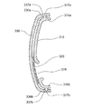
(回動パネル)
図4の(a)において、回動パネル310は、不透明な樹脂材料で成形された断面円弧状の板体である。回動パネル310の円弧状の端部311a、311bには凹面側に突出した端部フランジ312a、312bが形成されると共に、筐体115に着脱自在かつ回動自在に設置するための支点となる支持腕313a、313bと、筐体115に着脱不能かつ回動不能に固定するための係止爪314a、314bと、が形成されている。
また、回動パネル310の直線状の側部315a、135bには凹面側に突出した側部フランジ316a、316bが形成されると共に、前面パネル330を設置するための係止孔317a、317bが形成されている。
(Rotating panel)
In FIG. 4A, the
Further,
さらに、後記する投影装置200から出射された光を通すためのパネル開口部318a、318bが形成されている。なお、パネル開口部318a、318bは、投影装置200を形成する基板ホルダー240が侵入自在な大きさ(広がり)を有し、基板ホルダー240の形状や数量によって、その形状や数量が変動し、それぞれの形状が相違する場合がある。
さらに、センサーユニット400のセンシング範囲(赤外線の検出可能範囲)を確保するためのパネル切欠部319が形成されている。なお、センサーユニット400が設置されない場合には、当然に、パネル切欠部319は形成されないし、センサーユニット400が、回動パネル310の側縁部から離れ中央寄りに設置される場合には、パネル切欠部319は側縁部から離れパネル開口部(全周が包囲されている)を呈することになる。 なお、以下、共通する内容の説明においては、符号の添え字「a、b」の記載を省略する。
Further,
Further, a
(スクリーン)
図4の(b)において、回動パネル310の凸面側(表面に同じ)に、パネル開口部318a、318bを覆うスクリーン320a、320bが貼付されている。スクリーン320は厚さが0.1〜0.5mm程度(たとえば、約0.2mm)の可撓性を有するシート状で、半透明または不透明の樹脂材料であって、強い光(発光された出射光等)を透過させる一方、弱い光(発光しない物体からの反射光等)を遮蔽するものである。すなわち、発光しない物体を覆い隠す(発光しない物体の有無を視認できない状態にする)ことができるものである。
そして、回動パネル310と同色で同柄(たとえば、共に無地)であるから、スクリーン320の周縁は不明りょうで、貼付されていることが分かり難くなっている。なお、スクリーン320を1枚にして、回動パネル310と略同じ大きさ(広がり)にしておけば、スクリーン320の周縁が回動パネル310の周縁に略一致するから、両者の色彩や模様が相違する場合であっても、両者の境界が不明りょうになり、貼付されていることが分かり難くなる。
(screen)
In FIG. 4B, screens 320 a and 320 b covering the
And since it is the same color and the same pattern (for example, both are plain) as the
(前面パネル)
図4の(c)において、前面パネル330は、透明または半透明な樹脂材料で成形され、回動パネル310の曲面の曲率半径と略同じ曲率半径の曲面を具備する断面円弧状の板体であって、回動パネル310の凸面側(表面に同じ)を覆うものである。すなわち、前面パネル330の円弧状の端部331a、331bには凹面側に突出した端部フランジ332a、332bが形成され、剛性を高めている。
また、前面パネル330の直線状の側部335a、335bには凹面側に突出した側部フランジ336a、336bが形成され、側部フランジ336a、336bには、回動パネル310に形成された係止孔317a、317bに係止する係止突起337a、337bが形成されている。
(Front panel)
4C, the
Further,
また、回動パネル310に準じて、センサーユニット400のセンシング範囲(赤外線の検出可能範囲)を確保するためのパネル切欠部339が形成されているが、センサーユニット400が設置されない場合や設置位置が変動した場合には、パネル切欠部339は形成されなかったり、パネル開口部が形成されたりする。
さらに、前面パネル330の凹面は平坦面(平滑面)に限定するものではなく、シボ加工によって細かい凹凸が形成されたものであってもよい。このとき、投影された文字や図形が軟らかく浮き上がるから、高級感が増すと共に、塵埃等が付着してもこれが目立たなくなるから、清潔感が増す。
In addition, a
Furthermore, the concave surface of the
図5において、回動パネル310に形成された係止孔317a、317bに係止突起337a、337bを係止(陥入)することによって、前面パネル330はスクリーン320を挟んで回動パネル310に一体的に接合される。このとき、前面パネル330の前面(端部フランジ332a、332bおよび側部フランジ336a、336bを除く範囲)には、回動パネル310に接合するための手段(接着剤、ネジ、係止手段等)がないから、前面の景色が簡素であって、意匠性に優れている。
In FIG. 5, the locking
このとき、スクリーンを貼り付ける作業に際し、マスキング作業や膜厚管理が不要になるから、製造コストが安価になる。また、前面パネルの形状に関わらず所望の範囲にスクリーンを貼付することができる。たとえば、スクリーンと回動パネルとを略同じ大きさ(広がり)にしておけば、スクリーンの周縁が回動パネルの周縁に略一致するから、仮に両者の色彩や模様が相違する場合であっても、両者の境界が不明りょうになり意匠性が担保される。
さらに、貼付されたスクリーンを剥がすだけで、前面パネル330を容易にリサイクルすることができるから、再資源化が促進され、環境保全に好適である。
なお、図5は模式的に示すものであって、スクリーン320の厚さや、前面パネル330と回動パネル310との間隔は誇張して描いている。すなわち、前面パネル330の後面(図中、右側の面)と回動パネル310の表面(図中、左側の面)とは、当接または近接している。また、前面パネル330に係止孔を形成して、かかる係止孔に係止する係止突起を回動パネル310に形成してもよい。
At this time, since the masking operation and the film thickness management are not required in the operation of attaching the screen, the manufacturing cost is reduced. Moreover, a screen can be stuck in a desired range regardless of the shape of the front panel. For example, if the screen and the rotating panel are approximately the same size (expanded), the peripheral edge of the screen substantially coincides with the peripheral edge of the rotating panel, so even if the colors and patterns of the two differ. , The boundary between the two becomes unclear and the design is guaranteed.
Furthermore, since the
FIG. 5 schematically shows the thickness of the
(投影装置の構成)
次に、投影装置について詳細に説明する。
図6〜図8は本発明の実施の形態1に係る空気調和機の室内機に設置された投影装置を説明するものであって、図6は構成部材を分解して示す斜視図、図7は構成部材を組み立てた状態を示す側面視の断面図、図8は室内機に設置された状態を示す側面視の部分断面図である。
図6および図7において、水平方向の左右に投影装置200a、200bが設置されている。両者は表示内容が相違するものの構成は同じであるから、同じ内容については、符号の添え字「a、b」を省略する。投影装置200は、枠状の投影装置カバー220と、表示内容が印刷された印刷シート230と、印刷シート230が前面に貼付された基板ホルダー240と、基板ホルダー240にネジ止めされる基板250と、板状の投影装置ベース260と、を有している。
(Configuration of the projection device)
Next, the projection apparatus will be described in detail.
6 to 8 illustrate a projection apparatus installed in the indoor unit of the air conditioner according to Embodiment 1 of the present invention. FIG. 6 is an exploded perspective view showing components, FIG. FIG. 8 is a side sectional view showing the assembled state of the structural members, and FIG. 8 is a partial sectional view in side view showing the state where it is installed in the indoor unit.
6 and 7,
(投影装置カバー)
投影装置カバー220は、樹脂材料で成形され、カバー内壁221およびカバー外壁222を具備する断面略J字状の枠体である。カバー外壁222には、投影装置カバー220を投影装置ベース260に設置するためのカバー孔223が複数箇所に形成されている。
(Projector cover)
The
(印刷シート)
印刷シート230は、スクリーン320に投影される数字や図形(記号、イラスト等)の輪郭が縁取り印刷(マスキングに同じ)されたもので、基板ホルダー240の前面に接着剤で貼り付けられている。
なお、印刷シート230の光が通過する範囲(マスキングによって覆われた範囲を除く範囲)は、無色であっても所定の色彩を有してもよい。また、前記数字や図形は、運転状態等を意味するものであって、たとえば、運転モード(冷房、暖房、乾燥、強弱(緩急)等)、設定温度(℃)、当該運転を開始してからの消費電力量(kWh)、消費電力量に対応した電気代(円)、消費電力量を二酸化炭素の排出量に換算した値(kg)、あるいは、それらの月間(週間)累計値等の何れか1以上であるが、これらに限定するものではない。
(Print sheet)
The printed
In addition, the range (the range excluding the range covered by masking) through which the light of the
(基板ホルダー)
基板ホルダー240は、ABS等の樹脂材料によってボックス状に成形され、ホルダー前面241の表面に印刷シート230が貼付され、ホルダー前面241には、基板250に実装された発光手段(LED)251が挿入されるホルダー投光窓242が形成されている。ホルダー投光窓242の大きさ(開口面積)は、これに挿入される発光手段251の数量(1個または2個以上)に応じて決定されている。
そして、基板ホルダー240は、投影装置ベース260と投影装置カバー220とによって形成される函体に抜け出し不能に収納されている。このとき、基板ホルダー240のホルダー前面241の外周に沿ってホルダー筒部243が形成され、ホルダー筒部243の先端の外周に、複数のホルダーフランジ244が設けられている。
(Substrate holder)
The
The
(基板)
基板250には、表示手段としての発光手段(たとえば、LED)251が実装され、基板ホルダー240(正確にはホルダー筒部243)にネジ止めされている。発光手段251の出射する光の強さや色彩は限定するものではない。
(substrate)
A light emitting means (for example, LED) 251 as a display means is mounted on the
(投影装置ベース)
投影装置ベース260は、ABS等の樹脂材料から成形されており、投影装置カバー220のカバー外壁222の内側に侵入自在なベース筒部261を有し、ベース筒部261には投影装置カバー220のカバー孔223に陥入自在なベース突起262が形成されている。したがって、投影装置ベース260と投影装置カバー220とは、前者のベース突起262が後者のカバー孔223に陥入した状態で、一体化し、カバー内壁221によって囲まれた開口部を有する函体を形成している。
そして、投影装置ベース260は、筐体115に設置されている。
なお、投影装置ベース260に突出する回動用アーム(図示しない)を設け、回動用アームの先端を筐体115に回動自在または着脱自在に設置することによって、投影装置200を回動自在または着脱自在、すなわち、前面開口部116から移動自在または撤去自在にしてもよい。
(Projector base)
The
The
Note that a projection arm 200 (not shown) protruding from the
(付勢手段)
前記函体の内部には左右両側に付勢手段(たとえば、コイルバネ)290が配設され、基板ホルダー240を投影装置ベース260から離れる方向に付勢している。したがって、基板ホルダー240のホルダー前面241(その表面に印刷シート230が貼付されている)は、カバー内壁221によって囲まれた開口部を貫通して、前記函体の外部に突出している。
このとき、基板ホルダー240のホルダーフランジ244は投影装置カバー220(投影装置ベース260に固定されている)のカバー内壁221の端部に当接するから、基板ホルダー240が前記函体から抜け出すことがない。
(Biasing means)
Biasing means (for example, coil springs) 290 are disposed on the left and right sides inside the box to urge the
At this time, the
(発光手段の点灯状況)
図8において、回動パネル310が閉じて前面開口部116を塞いだ際、回動パネル310のパネル開口部318に、投影装置200を形成する基板ホルダー240の先端部(前面寄りの範囲)が侵入している。そして、前面パネル330の裏面が、スクリーン320を挟んで基板ホルダー240の前面(印刷シート230)を後面方向に押し込んでいる。したがって、仮に、前面パネル330に反り等がある場合でも、前面パネル330の裏面にスクリーン320および印刷シート230が互いに密着して押し付けられることになる。
そして、スクリーン320と前面パネル330とが重なった状態は半透明または不透明であるものの、発光手段251からの出射光はこれを透過するから、発光手段251を点灯することによって、印刷シート230に印刷された数字や図形が、前面パネル330の前面に投影されることになる。すなわち、複数の発光手段251の点灯要領を変更することによって、必要な運転状態等が使用者に周知されることになるから、使用者の意識を喚起し、省エネ運転が促進される。
このとき、前面パネル330の簡素な面に、数字や図形が光によって浮き上がるように表示されるから、機能性が担保されると共に、清涼感および高級感が醸し出され、室内機100の商品価値が向上する。
(Lighting status of light emitting means)
In FIG. 8, when the
Although the state where the
At this time, since numbers and figures are displayed on the simple surface of the
(発光手段の消灯状況)
一方、スクリーン320と前面パネル330とが重なった状態は半透明または不透明であって、弱い光(発光しない物体からの反射光等)を遮蔽するものであるから、発光手段251を消灯することによって、印刷シート230や基板ホルダー240等の投影装置200を構成する部材が、覆い隠され、室内機100の外部からこれを視認することができない。すなわち、使用者は、前面パネル330の裏側(後面寄りの位置)に投影装置200が設置されていることに気付かなくなる。
そして、前面パネル330には、開口部がなく、又、接着剤が付着した痕跡や前面パネル330の奥にあるものの影が透過しない。したがって、前面パネル330は、それ自体が簡素な面を有し、意匠性が阻害されることなく、清涼感および高級感が維持され、室内機100の商品価値が向上している。
なお、パネル開口部の大きさや形状は限定されるものではないから、パネル開口部を大きくして、運転状態等(たとえば、二酸化炭素排出量)を大きく且つ明りょうに表示することによって、使用者の意識に訴え(たとえば、設定温度の調整を促し)、省エネの促進に寄与することが可能になる。
(Light emission means off status)
On the other hand, the state where the
The
Since the size and shape of the panel opening are not limited, it is possible to enlarge the panel opening and display the operating state (for example, carbon dioxide emissions) in a large and clear manner. (For example, prompting the user to adjust the set temperature) and contributing to the promotion of energy saving.
(センサーユニット)
さらに、投影装置200に挟まれて運転制御のためのセンサーユニット400が配置されている。センサーユニット400はセンサー本体401と、センサー本体401を揺動させられる(所定の回転角度の間を往復する)センサーモーター402と、を有し、センサーモーター402が筐体115に固定されている。
また、回動パネル310にはパネル切欠部319が、前面パネル330にはパネル切欠部339がそれぞれ形成されているから、回動パネル310が室内機本体110の前面開口部116を覆った際、センサーユニットのセンシング範囲が確保されている。
(Sensor unit)
Further, a
In addition, since the
したがって、回動パネル310(前面パネル330が一体的に接合されている)が室内機本体110の前面開口部116を覆った状態で、センサー本体401は、室内の広い範囲をセンシングすることが可能になっている。
なお、センサー本体401は、室内の温度分布(人間の位置を含む)や人間の体感温度、あるいは室内空気に含まれる塵埃の量等を検知するものであるが、これに限定するものではない。また、本発明はセンサーユニット400の種類や形状を限定するものではなく、さらに、センサーユニット400の設置を省略してもよい。
Therefore, the sensor main body 401 can sense a wide range in the room with the rotating panel 310 (with the
The sensor body 401 detects the temperature distribution in the room (including the position of the person), the temperature sensed by the person, or the amount of dust contained in the room air, but is not limited to this. Further, the present invention does not limit the type or shape of the
[実施の形態2]
(空気調和機の室内機−その2)
図9および図10は本発明の実施の形態2に係る空気調和機の室内機を説明するものであって、図9は一部(前面パネル)を分解して示す斜視図、図10は一部の設置状況を示す側面視の断面図である。なお、実施の形態1と同じ部分または相当する部分には同じ符号を付し、一部の説明を省略する。また、各図は模式的に描いたものであって、本発明は図示された形態に限定するものではない。
図9および図10において、本発明の実施の形態2に係る空気調和機の室内機は、実施の形態1に示す室内機1における、回動パネル310、スクリーン320、前面パネル330および投影装置200を、それぞれ、回動パネル510、スクリーン520、前面パネル530および投影装置600に、変更したものであって、これを除く構成は、室内機100に同じである。以下、相違点について説明する。
[Embodiment 2]
(Air conditioner indoor unit-2)
9 and 10 illustrate an indoor unit of an air conditioner according to Embodiment 2 of the present invention. FIG. 9 is an exploded perspective view showing a part (front panel), and FIG. It is sectional drawing of the side view which shows the installation condition of a part. In addition, the same code | symbol is attached | subjected to the part which is the same as that of Embodiment 1, or an equivalent part, and one part description is abbreviate | omitted. Each figure is drawn typically and the present invention is not limited to the illustrated form.
9 and 10, the indoor unit of the air conditioner according to Embodiment 2 of the present invention is the
(回動パネル等)
図9において、回動パネル510は、回動パネル310に形成されたパネル開口部318a、318bに替えて、パネル中央に大きなパネル開口部318cが形成され、一方、回動パネル310に形成されたパネル切欠部319が撤去されている。
スクリーン520は、実施の形態1におけるスクリーン320と同じ材質によって形成され、回動パネル510の後面(凹面)の略全域を覆う大きさの1枚物である。
前面パネル530は、実施の形態1における前面パネル330に形成されたパネル切欠部319を撤去したものに同じである。
(Rotating panel etc.)
In FIG. 9, the
The
(投影装置)
図10において、投影装置600は、図示しない筐体115に付勢手段(コイルスプリング)690によって弾性的に支持された投影装置ベース660と、投影装置ベース660に固定された基板ホルダー640と、基板ホルダー640に保持された基板250と、基板250に搭載された発光手段(LED)251と、を有している。
(Projector)
In FIG. 10, a
(基板ホルダー)
基板ホルダー640は、ABS等の樹脂材料によってボックス状に成形され、外周に沿って形成されたホルダー筒部643が投影装置ベース660に接合され、内部にホルダー隔壁644が形成されている。ホルダー隔壁644は基板250を支持すると共に、複数のホルダー投光窓642を形成している。
そして、ホルダー投光窓642には、基板250に搭載された発光手段(LED)251が挿入されている。なお、ホルダー投光窓642の大きさ(開口面積)は、これに挿入される発光手段251の数量(1個または2個以上)に応じて決定されている。
(Substrate holder)
The substrate holder 640 is formed in a box shape from a resin material such as ABS, and a
A light emitting means (LED) 251 mounted on the
(投影装置ベース)
投影装置ベース660は、ABS等の樹脂材料から成形されており、基板ホルダー640が接合されている。
そして、投影装置ベース660は付勢手段690によって、筐体115(図示しない)に弾性的に設置されている。
(Projector base)
The
The
(発光手段の点灯状況)
したがって、回動パネル310が閉じて前面開口部116を塞いだ際、回動パネル310のパネル開口部318cに、投影装置600を形成する基板ホルダー640の先端部(前面寄りの範囲)が侵入する。そして、前面パネル330の裏面が、スクリーン320を挟んで基板ホルダー640のホルダー前面641(ホルダー隔壁644の前面側の端部を含む)を後面方向に押し込んでいる。したがって、仮に、前面パネル330に反り等がある場合でも、前面パネル330の裏面にスクリーン320が互いに密着して押し付けられることになる。
このとき、基板ホルダー640は、ホルダー隔壁644の前面側の端部がスクリーン320に密着しているから、所定のホルダー投光窓642に出射された光が、これに隣接するホルダー投光窓642に漏れることがない。
そして、スクリーン320と前面パネル330とが重なった状態は半透明または不透明であるものの、発光手段251からの出射光はこれを透過するから、複数の発光手段251の点灯要領を変更することによって、所望の光の像を前面パネル330の前面に鮮明に投影することができる。すなわち、運転状態等と関連付けた光の像にすることによって、必要な運転状態等が使用者に周知されることになるから、使用者の意識を喚起し、省エネ運転が促進される。
このとき、前面パネル330の簡素な面に、数字や図形が光によって浮き上がるように表示されるから、機能性が担保されると共に、清涼感および高級感が醸し出され、室内機100の商品価値が向上する。
(Lighting status of light emitting means)
Therefore, when the
At this time, since the substrate holder 640 has the front end of the
And although the state where the
At this time, since numbers and figures are displayed on the simple surface of the
(発光手段の消灯状況)
一方、スクリーン320と前面パネル330とが重なった状態は半透明または不透明であって、弱い光(発光しない物体からの反射光等)を遮蔽するものであるから、発光手段251を消灯することによって、基板ホルダー640のホルダー前面641や発光手段251等の投影装置600を構成する部材が、覆い隠され、外部からこれを視認することができない。すなわち、使用者は、前面パネル330の裏側(後面寄りの位置)に投影装置600が設置されていることに気付かなくなる。
したがって、実施の形態1に示す室内機100と同様に、清涼感および高級感が維持され、商品価値が向上している。
なお、以上は、投影装置600が印刷シートを具備しないものを示しているが、本発明はこれに限定するものではなく、ホルダー前面641に実施の形態1に示す印刷シート230を貼付してもよい。さらに、センサーユニットの設置あるいは配置位置に応じて、パネル切欠部を形成してもよい。
(Light emission means off status)
On the other hand, the state where the
Therefore, like the
In the above, the
100;室内機、110;室内機本体、111;吸引口、112;風路、113;吹出口、114;基台、115;筐体、116;前面開口部、117;前面上下風向ベーン、118;下面上下風向ベーン、120;送風手段、130;熱交換手段、131;伝熱管、132;放熱フィン、140;ドレンパン、150;フィルター自動清掃ユニット、151;フィルター、152;ダストボックス、160;制御ユニット、200;投影装置、200a;投影装置、220;投影装置カバー、221;カバー内壁、222;カバー外壁、223;カバー孔、230;印刷シート、240;基板ホルダー、241;ホルダー前面、242;ホルダー投光窓、243;ホルダー筒部、244;ホルダーフランジ、250;基板、251;発光手段、260;投影装置ベース、261;ベース筒部、262;ベース突起、310;回動パネル、311a;端部、312a;端部フランジ、313a;支持腕、314a;係止爪、315a;側部、316a;側部フランジ、317a;係止孔、318;パネル開口部、319;パネル切欠部、320;スクリーン、330;前面パネル、331;端部、332;端部フランジ、335;側部、336;側部フランジ、337;係止突起、339;パネル切欠部、400;センサーユニット、401;センサー本体、402;センサーモーター、520;スクリーン、530;前面パネル、600;投影装置、640;基板ホルダー、641;ホルダー前面、642;ホルダー投光窓、643;ホルダー筒部、644;ホルダー隔壁、660;投影装置ベース、690;付勢手段。
100; Indoor unit, 110; Indoor unit body, 111; Suction port, 112; Air passage, 113; Air outlet, 114; Base, 115; Housing, 116; Front opening, 117; ; Bottom vertical wind direction vane, 120; air blowing means, 130; heat exchange means, 131; heat transfer pipe, 132; heat radiation fin, 140; drain pan, 150; filter automatic cleaning unit, 151; filter, 152; dust box, 160; , 200; Projector, 200a; Projector, 220; Projector cover, 221; Cover inner wall, 222; Cover outer wall, 223; Cover hole, 230; Print sheet, 240; Substrate holder, 241; Holder front, 242; Projection window, 243; holder tube portion, 244; holder flange, 250; substrate, 251; 260; Projector base 261; Base tube portion 262; Base projection 310; Rotating panel 311a End portion 312a End flange 313a Support arm 314a Locking claw 315a Side 316a; side flange, 317a; locking hole, 318; panel opening, 319; panel notch, 320; screen, 330; front panel, 331; end, 332; end flange, 335; 336; side flange, 337; locking projection, 339; panel cutout, 400; sensor unit, 401; sensor body, 402; sensor motor, 520; screen, 530; front panel, 600; Holder, 641; Holder front surface, 642; Holder projection window, 643; Holder cylinder, 644; Holder partition, 66 ; Projector base, 690; biasing means.
Claims (9)
該室内機本体に設置され、前記本体開口部を覆い且つ開放する回動パネルと、
該回動パネルに貼付され、該回動パネルに形成されたパネル開口部を覆うスクリーンと、
前記回動パネルに設置され、前記回動パネルの前面を覆う前面パネルと、
前記パネル開口部に向けて光を出射することができる発光手段を具備する投影装置と、
を有し、
前記回動パネルが不透明材料によって形成され、
前記前面パネルが透明材料または半透明材料によって形成され、
前記スクリーンが半透明材料または不透明材料によって形成され、
前記回動パネルが室内機本体の前面開口部を覆い、且つ、前記発光手段が消灯している時は、前記前面パネルおよび前記スクリーンによって前記投影装置が覆い隠され、
前記回動パネルが室内機本体の前面開口部を覆い、且つ、前記発光手段が点灯している時は、前記発光手段が出射する光が前記スクリーンに投影されるとともに、前記スクリーンおよび前記前面パネルを透過し、
前記投影装置は、
前記室内機本体に設置され、
前記発光手段が設けられた基板と、
前記基板が固定され、前記発光手段を収納するように前記投影装置側から前記前面パネル側に突出して形成されたホルダー筒部、及び、該ホルダー筒部の前面側であって前記発光手段との対向位置に形成されたホルダー投光窓を有する基板ホルダーと、
前記ホルダー投光窓を覆うように前記ホルダー筒部の前面側に貼付され、前記スクリーンに投影される内容が印刷された印刷シートと、
を有し、
前記回動パネルが室内機本体の前面開口部を覆った際、前記スクリーンが前記印刷シートを介して、前記基板ホルダーの前記ホルダー筒部によって前記前面パネルの後面に押し付けられる
ことを特徴とする空気調和機の室内機。 An indoor unit body having a main body opening on the front surface;
A rotating panel installed in the indoor unit main body and covering and opening the main body opening;
A screen affixed to the rotating panel and covering a panel opening formed in the rotating panel;
A front panel that is installed on the rotating panel and covers a front surface of the rotating panel;
A projection apparatus comprising light emitting means capable of emitting light toward the panel opening;
Have
The pivot panel is formed of an opaque material;
The front panel is formed of a transparent or translucent material;
The screen is formed of a translucent or opaque material;
When the rotating panel covers the front opening of the indoor unit main body and the light emitting means is turned off, the projection device is covered by the front panel and the screen,
When the rotating panel covers the front opening of the indoor unit main body and the light emitting means is lit, the light emitted from the light emitting means is projected onto the screen, and the screen and the front panel through the,
The projector is
Installed in the indoor unit body,
A substrate provided with the light emitting means;
A holder cylinder portion formed to protrude from the projection apparatus side to the front panel side so as to accommodate the light emitting means, and a front side of the holder cylinder portion and the light emitting means A substrate holder having a holder projection window formed in an opposing position;
A printed sheet on which the content projected on the screen is printed, which is affixed to the front surface side of the holder cylinder so as to cover the holder projection window;
Have
When the rotating panel covers the front opening of the indoor unit main body, the screen is pressed against the rear surface of the front panel by the holder tube portion of the substrate holder via the printing sheet. The indoor unit of the harmony machine.
ことを特徴とする請求項1記載の空気調和機の室内機。 The indoor unit of an air conditioner according to claim 1, wherein the screen covers the entire front surface of the rotating panel.
ことを特徴とする請求項1または2記載の空気調和機の室内機。 The indoor unit of the air conditioner according to claim 1 or 2, wherein irregularities are formed on the rear surface of the front panel by a texture process.
前記回動パネルの側縁に形成されたフランジと、前記前面パネルの側縁に形成されたフランジと、が係止手段によって着脱自在に係止されている
ことを特徴とする請求項1乃至3の何れかに記載の空気調和機の室内機。 The rotating panel and the front panel are cross-sectional arc plates having substantially the same radius of curvature,
The flange formed in the side edge of the said rotation panel and the flange formed in the side edge of the said front panel are detachably latched by the latching means. The indoor unit of the air conditioner according to any one of the above.
ことを特徴とする請求項1乃至4の何れかに記載の空気調和機の室内機。 At both ends of the rotating panel, a support arm for being rotatably installed in the indoor unit main body and a locking claw for being fixed to the indoor unit main body so as not to rotate are formed. The air conditioner indoor unit according to any one of claims 1 to 4, wherein the indoor unit is an air conditioner indoor unit.
ことを特徴とする請求項1乃至5の何れかに記載の空気調和機の室内機。 The indoor unit of an air conditioner according to any one of claims 1 to 5, wherein the screen has substantially the same color or substantially the same pattern as the rotating panel.
前記投影装置は、前記基板ホルダーを保持する投影装置ベースを有する
ことを特徴とする請求項1乃至6の何れかに記載の空気調和機の室内機。 The screen is a sheet having flexibility,
The projection apparatus, prior Symbol indoor unit of an air conditioner according to any one of claims 1 to 6, characterized in that have a projection device database that holds the substrate holder.
ことを特徴とする請求項7記載の空気調和機の室内機。 The air conditioner indoor unit according to claim 7, wherein a biasing means is provided between the substrate holder and the projection apparatus base.
ことを特徴とする請求項7記載の空気調和機の室内機。 The indoor unit of an air conditioner according to claim 7, wherein the substrate holder forming the projection device is installed in the indoor unit main body through an urging means.
Priority Applications (1)
| Application Number | Priority Date | Filing Date | Title |
|---|---|---|---|
| JP2009213260A JP5264662B2 (en) | 2009-09-15 | 2009-09-15 | Air conditioner indoor unit |
Applications Claiming Priority (1)
| Application Number | Priority Date | Filing Date | Title |
|---|---|---|---|
| JP2009213260A JP5264662B2 (en) | 2009-09-15 | 2009-09-15 | Air conditioner indoor unit |
Publications (3)
| Publication Number | Publication Date |
|---|---|
| JP2011064351A JP2011064351A (en) | 2011-03-31 |
| JP2011064351A5 JP2011064351A5 (en) | 2011-09-22 |
| JP5264662B2 true JP5264662B2 (en) | 2013-08-14 |
Family
ID=43950798
Family Applications (1)
| Application Number | Title | Priority Date | Filing Date |
|---|---|---|---|
| JP2009213260A Active JP5264662B2 (en) | 2009-09-15 | 2009-09-15 | Air conditioner indoor unit |
Country Status (1)
| Country | Link |
|---|---|
| JP (1) | JP5264662B2 (en) |
Families Citing this family (5)
| Publication number | Priority date | Publication date | Assignee | Title |
|---|---|---|---|---|
| JP5506754B2 (en) * | 2011-08-29 | 2014-05-28 | 三菱電機株式会社 | Air conditioner indoor unit |
| JP5611153B2 (en) * | 2011-08-30 | 2014-10-22 | 三菱電機株式会社 | Air conditioner indoor unit |
| JP5709701B2 (en) * | 2011-09-07 | 2015-04-30 | 三菱電機株式会社 | Indoor unit of air conditioner and air conditioner equipped with the same |
| CN103807993A (en) * | 2012-11-14 | 2014-05-21 | 珠海格力电器股份有限公司 | Air conditioner pattern display structure and air conditioner comprising same |
| WO2019167112A1 (en) * | 2018-02-27 | 2019-09-06 | 三菱電機株式会社 | Indoor unit for air conditioner |
Family Cites Families (5)
| Publication number | Priority date | Publication date | Assignee | Title |
|---|---|---|---|---|
| JP3951936B2 (en) * | 2003-02-25 | 2007-08-01 | 松下電器産業株式会社 | Air conditioner indoor unit |
| JP2006112701A (en) * | 2004-10-14 | 2006-04-27 | Matsushita Electric Ind Co Ltd | Indoor unit of air conditioner |
| JP2008133969A (en) * | 2006-11-27 | 2008-06-12 | Sharp Corp | Air conditioner |
| JP5127614B2 (en) * | 2007-10-03 | 2013-01-23 | 三菱電機株式会社 | Air conditioner indoor unit |
| JP2009198104A (en) * | 2008-02-22 | 2009-09-03 | Corona Corp | Air conditioner |
-
2009
- 2009-09-15 JP JP2009213260A patent/JP5264662B2/en active Active
Also Published As
| Publication number | Publication date |
|---|---|
| JP2011064351A (en) | 2011-03-31 |
Similar Documents
| Publication | Publication Date | Title |
|---|---|---|
| JP5264662B2 (en) | Air conditioner indoor unit | |
| JP5611153B2 (en) | Air conditioner indoor unit | |
| JP5127614B2 (en) | Air conditioner indoor unit | |
| JP5660937B2 (en) | Air conditioner indoor unit | |
| JP2009079787A (en) | Indoor unit of air conditioner | |
| JP5258696B2 (en) | Air conditioner indoor unit | |
| US7946712B2 (en) | Projector apparatus equipped with a structure capable of shielding radiation and dissipating heat from a light source | |
| CN110470098A (en) | A kind of refrigerator unbounded area source and its manufacture craft | |
| KR20030084734A (en) | Indoor unit of an air conditioner | |
| KR20140089068A (en) | Air conditioner | |
| JP4045147B2 (en) | Air conditioner | |
| JP5173957B2 (en) | Air conditioner indoor unit | |
| US20080055570A1 (en) | Projector apparatus | |
| KR20100055910A (en) | Back lighting unit and air conditioner having the same | |
| KR101447755B1 (en) | Indoor unit for air conditioning apparatus | |
| CN211427751U (en) | Multifunctional LED transparent screen | |
| JP4864130B2 (en) | Air conditioner indoor unit | |
| JP2011064351A5 (en) | ||
| KR101402156B1 (en) | Air conditioner | |
| CN215675474U (en) | Air conditioner | |
| WO2022001488A1 (en) | Light-emitting device | |
| KR100884047B1 (en) | Air conditioner | |
| KR20090098516A (en) | Air conditioner | |
| JP2008025912A (en) | Humidifier | |
| JP2002228183A (en) | Air conditioner |
Legal Events
| Date | Code | Title | Description |
|---|---|---|---|
| A521 | Request for written amendment filed |
Free format text: JAPANESE INTERMEDIATE CODE: A523 Effective date: 20110809 |
|
| A621 | Written request for application examination |
Free format text: JAPANESE INTERMEDIATE CODE: A621 Effective date: 20110809 |
|
| A977 | Report on retrieval |
Free format text: JAPANESE INTERMEDIATE CODE: A971007 Effective date: 20121012 |
|
| A131 | Notification of reasons for refusal |
Free format text: JAPANESE INTERMEDIATE CODE: A131 Effective date: 20121023 |
|
| A521 | Request for written amendment filed |
Free format text: JAPANESE INTERMEDIATE CODE: A523 Effective date: 20121217 |
|
| TRDD | Decision of grant or rejection written | ||
| A01 | Written decision to grant a patent or to grant a registration (utility model) |
Free format text: JAPANESE INTERMEDIATE CODE: A01 Effective date: 20130402 |
|
| A61 | First payment of annual fees (during grant procedure) |
Free format text: JAPANESE INTERMEDIATE CODE: A61 Effective date: 20130430 |
|
| R150 | Certificate of patent or registration of utility model |
Free format text: JAPANESE INTERMEDIATE CODE: R150 Ref document number: 5264662 Country of ref document: JP Free format text: JAPANESE INTERMEDIATE CODE: R150 |
|
| R250 | Receipt of annual fees |
Free format text: JAPANESE INTERMEDIATE CODE: R250 |
|
| R250 | Receipt of annual fees |
Free format text: JAPANESE INTERMEDIATE CODE: R250 |
|
| R250 | Receipt of annual fees |
Free format text: JAPANESE INTERMEDIATE CODE: R250 |
|
| R250 | Receipt of annual fees |
Free format text: JAPANESE INTERMEDIATE CODE: R250 |
|
| R250 | Receipt of annual fees |
Free format text: JAPANESE INTERMEDIATE CODE: R250 |
|
| R250 | Receipt of annual fees |
Free format text: JAPANESE INTERMEDIATE CODE: R250 |
|
| R250 | Receipt of annual fees |
Free format text: JAPANESE INTERMEDIATE CODE: R250 |
|
| R250 | Receipt of annual fees |
Free format text: JAPANESE INTERMEDIATE CODE: R250 |
|
| R250 | Receipt of annual fees |
Free format text: JAPANESE INTERMEDIATE CODE: R250 |