JP2013170787A - Indoor unit of air conditioner - Google Patents
Indoor unit of air conditioner Download PDFInfo
- Publication number
- JP2013170787A JP2013170787A JP2012036199A JP2012036199A JP2013170787A JP 2013170787 A JP2013170787 A JP 2013170787A JP 2012036199 A JP2012036199 A JP 2012036199A JP 2012036199 A JP2012036199 A JP 2012036199A JP 2013170787 A JP2013170787 A JP 2013170787A
- Authority
- JP
- Japan
- Prior art keywords
- light
- display
- indoor unit
- display device
- air conditioner
- Prior art date
- Legal status (The legal status is an assumption and is not a legal conclusion. Google has not performed a legal analysis and makes no representation as to the accuracy of the status listed.)
- Pending
Links
Images


Abstract
Description
本発明は、運転状態を色分け表示する表示装置を備えた空気調和機の室内機に関するものである。 The present invention relates to an indoor unit of an air conditioner provided with a display device that displays an operation state by color.
近年の空気調和機の室内機に備えられた表示装置は、空気調和機の運転状態に応じて、発光色の異なる発光体を発光させ、色の違いにより運転状態をユーザーが識別できるようにしている。
例えば、特許文献1は、前面下部吸込口に連なる通風路壁の上端部に設置された光透過性半透明材料からなる帯状部材と、この帯状部材に一体的に設けられ、横方向に所定間隔で複数配設し、光透過性光学系部材で形成し、下方から光を受ける受光面と受光面上方に受光面から入った光を前方に屈曲反射させる反射面と反射面の前方で前面吸込口内の通風路壁に連通する上部位置に反射された光が送られる発光体と同程度の大きさの発光表示部を複数備えた運転状態表示と、この運転状態表示部へ光を照射する複数個の発光体を有する発光源を備え、運転状態に応じて、照射する位置や色を変えて、運転状態をユーザーに知らせている。
A display device provided in an indoor unit of a recent air conditioner emits light emitters having different emission colors according to the operation state of the air conditioner, and enables the user to identify the operation state based on the difference in color. Yes.
For example,
また、特許文献2では、表示部から光源(LED)までの所定の距離を確保し、表示部に投射される形は大きな四角形となって光源の発光部面積よりも拡大させることで、ユーザーへの識別性を向上させているものがある。
Further, in
なお、本明細書では、空気調和機の運転状態をユーザーに知らせるために、光を照射する部分のことを表示部とする。 In this specification, in order to inform the user of the operating state of the air conditioner, a portion that emits light is referred to as a display unit.
特許文献1における空気調和機の室内機の表示装置は、光源一つに対して光源と同程度の大きさの表示部に光を照射させているが、表示部が狭いため、ユーザーから運転状態が識別され難いという問題がある。そこで、複数の光源を設け、一つの広範囲の表示部に光を照射させようとすると、表示部に照射させた際に、表示部における明るさが、各々の光源に対向する部分とその周囲の部分とで明暗のバラツキが生じる。
特許文献2のように、表示部と光源との距離を長くすることで、光源よりも大きく広い範囲で照射させることができるが、それでも表示部における光源に対向する部分とその周囲の部分とで明暗のバラツキが生じる。また、光源がユーザーから視認されてしまい意匠性が悪いという問題もある。光源を視認させないためには、さらに距離を確保することで解決できるが、奥行きが小さい空気調和機の室内機の中に光源を設置しなければならない場合、それは現実的ではない。
The display device for an indoor unit of an air conditioner in
As in
本発明は、上記のような課題を解決するためになされたもので、奥行きが少ないスペースに設置された光源で広範囲の表示部を明暗のバラツキを小さく抑えて照射することができる表示装置を備えた空気調和機の室内機を提供することを目的としている。 The present invention has been made in order to solve the above-described problems, and includes a display device that can irradiate a wide range of display units with a small variation in brightness with a light source installed in a space with a small depth. The purpose is to provide indoor units for air conditioners.
本発明に係る空気調和機の室内機は、空気調和機の運転状態に応じて、表示部の色を変化させることができる表示装置を備えた室内機において、前記表示装置は、複数の光源と、前記光源から発射された光を反射する傾斜した反射面と、を少なくとも備え、前記光源から発射された光が、直接に、または前記反射面で反射し、前記表示部に集積する構成となっているものである。 An indoor unit of an air conditioner according to the present invention is an indoor unit including a display device capable of changing a color of a display unit according to an operating state of the air conditioner, wherein the display device includes a plurality of light sources, An inclined reflection surface that reflects light emitted from the light source, and the light emitted from the light source is reflected directly or by the reflection surface and is integrated in the display unit. It is what.
上記のように構成することにより、奥行きが少ないスペースに設置された光源で広範囲の表示部を明暗のバラツキを小さく抑えて照射することができ、ユーザーに空気調和機の運転状態を確実に知らせることができる。 By configuring as described above, it is possible to irradiate a wide range of display units with a small variation in brightness with a light source installed in a space with a small depth, and reliably notify the user of the operating condition of the air conditioner Can do.
以下、本発明に係る表示装置を備えた空気調和機の室内機の実施の形態を図面に基づいて説明する。 DESCRIPTION OF EMBODIMENTS Hereinafter, embodiments of an indoor unit of an air conditioner equipped with a display device according to the present invention will be described based on the drawings.
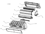
図1は本発明の実施の形態に係る空気調和機の室内機の全体を示す分解斜視図、図2はその室内機の断面図である。
図1および図2に示すように、この実施の形態に係る空気調和機の室内機100は、基台1、送風ファン2、熱交換器3、電気品箱4、ドレンパンユニット5、表示装置保持部6、表示装置7、筐体8、表示部意匠パネル9、上下に開閉可能な前面意匠パネル10を有している。基台1には送風ファン2、熱交換器3、電気品箱4、ドレンパンユニット5が装着される。送風ファン2によって室内機100の上面吸込口20より室内空気を吸い込み、熱交換器3を通過させることによって熱交換して、冷気または暖気とし、その冷気または暖気を、吹出口21より室内へ送風する。熱交換器3の表面に凝縮したドレン水はドレンパンユニット5に回収され、回収された水は、ドレンホース(図示せず)を流れて室外に排出される。
FIG. 1 is an exploded perspective view showing the whole indoor unit of an air conditioner according to an embodiment of the present invention, and FIG. 2 is a cross-sectional view of the indoor unit.
As shown in FIGS. 1 and 2, an indoor unit 100 of an air conditioner according to this embodiment includes a
表示装置7は、図2に示すように、室内機100の内部前面側に装着されており、室内機100の冷房、暖房、又は除湿の各運転状態に対して、表示部15に照射される光の色を変化させることで、ユーザーに運転状態を知らせるための装置である。例えば、暖房の場合は赤色、冷房の場合は青色、除湿の場合は緑色に表示される。
As shown in FIG. 2, the
表示装置7は、前面意匠パネル10の下方に配置され、ユーザーへの識別を容易にしている。また、表示装置7は表示装置保持部6のツメによって固定されている。表示装置保持部6はドレンパンユニット5にツメで固定され、さらに、表示部意匠パネル9によって上から押さえられている。表示部意匠パネル9は筐体8にツメで固定され、前面意匠パネル10によって上から押さえられている。すなわち、ユーザーは、室内機100の運転状態に応じて、表示装置7に表示される色を、室内機100の前面側下方に設けられた透光性の表示部意匠パネル9を通して確認することができる。なお、筐体8は基台1、ドレンパンユニット5にネジで固定されている。
The
図3は室内機100の正面図で、図4はその室内機100の表示部意匠パネル9を除いて示す正面図である。
表示装置7は、前面意匠パネル10と吹出口21との間に、室内機100の長手方向に細長い態様で配置されており、本例では、図4に示すように、正面の人感知センサー22に対し左右対称に配置されている。透光性を有する表示部意匠パネル9は、室内機100の全長とほぼ同じ長さとなっている。また、吹出口21には左右対称に一対の上下風向変更板23が開閉可能に設けられており、上下風向変更板23の奥側(吹き出し風路の内部)には図示しない左右風向変更板が設けられている。
人感知センサー22は、室内に居る人の場所を検知し、図示しない制御装置が、人感知センサー22の検知信号に基づいて、上下風向変更板23および左右風向変更板(図示せず)の向きをそれぞれ制御し、空気調和された空気を快適な方向に送風することを目的としたセンサーである。
FIG. 3 is a front view of the indoor unit 100, and FIG. 4 is a front view showing the indoor unit 100 except for the display
The
The
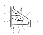
次に、図5〜図8を参照して、表示装置7の構造について説明する。
図5は本発明の実施の形態に係る表示装置7の分解斜視図、図6は図5の左側の表示装置7の正面図、図7は図6の表示装置7の表示パネル14を除いて示す正面図、図8は図7の表示装置7の斜視図である。なお、表示装置7は左側、右側とも同じ構成である。
Next, the structure of the
5 is an exploded perspective view of the
表示装置7は、表示装置筐体11、基板12、光源13、および表示パネル14を備えている。表示装置筐体11は、図7、図8に示すように、前面が開口した略三角形状の断面で奥行き寸法の短い形状をなしており、表示装置筐体11の内側の底面18上には複数の光源13が装着された基板12が設置され、表示装置筐体11の奥側には開口部方向に向けて光を広範囲に反射するように、傾斜した反射面(斜面)19が形成されている。また、表示装置筐体11の開口部には表示パネル14が接着剤により取り付けられている。光源13には、例えばLEDが用いられているが、これに限られるものではない。
The
基板12は、複数の光源13が並列に設置されており、表示装置筐体11の底面に例えばツメで固定されている。また、特許文献1と異なり、表示装置筐体11は基板12に設置された光源13と光源13の間に光を遮るものは存在しない。したがって、表示パネル14における表示部の明暗のバラツキを小さく抑えることができるとともに、構成の簡素化が可能になるという効果がある。また、光源13は一つの光源で3色(赤、青、緑)発光することが可能であり、室内機100の冷房、暖房、又は除湿の各運転モードに対して、発光の色を変えるようになっている。表示パネル14は、上側部分に光源13から発射された光を透過する表示部15と、下側部分に光源13をユーザーから直接見えなくさせるための光源遮蔽部16とで形成されている。
The substrate 12 has a plurality of light sources 13 arranged in parallel, and is fixed to the bottom surface of the display device casing 11 with, for example, a claw. Unlike
表示装置7の材料について説明する。表示装置筐体11は光源13からの光を反射できるように、白色樹脂材料で成形されている。表示パネル14の表示部15は透明樹脂材料で成形されている。光源遮蔽部16は光を透過しない樹脂材料で成形されている。
The material of the
次に、図9を参照して動作について説明する。図9は表示装置7の動作を説明するための概念図である。
この実施の形態に係る空気調和機の室内機100の表示装置7は、上記のように構成されているので、図9に示すように、複数の光源13から発射された光線17は広範囲に広がり、それらの光が直接に、または反射面19で反射し、表示パネル14方向に集積する。そのため、表示パネル14の表示部15全体が明暗のバラツキを小さく抑えて照射する。また、特許文献1とは異なり、直接的な光と間接的な光が表示パネル14に投射されることにより、間接的な光のみよりも多くの光が表示パネル14に照射されるため、表示部15を広範囲に照射させることが可能である。さらに、基板12に設置された光源13と光源13の間には光を遮るものは存在しないため、表示装置筐体11の中で光線17が交じり合い、明暗のバラツキを小さく抑える効果を高めることができる。なお、表示パネル14の表示部15に拡散効果を有する拡散材を混入させることで、さらに光を拡散することができる。また、室内機100の運転状態に応じて、光源13から発射される光の色を、例えば、暖房運転時は赤色、冷房運転時は青色、除湿運転時は緑色に変化させることにより、室内機100の運転状態をユーザーに明確に知らせることができる。
また、表示装置7の前面に光の透過が可能な色で着色された表示意匠パネル9を設けることにより、表示装置7をユーザーから目視され難くすることもできる。
Next, the operation will be described with reference to FIG. FIG. 9 is a conceptual diagram for explaining the operation of the
Since the
In addition, by providing the
以上のように、この実施の形態によれば、広範囲の表示部15を明暗のバラツキを小さく抑えて照射させることができ、ユーザーに空気調和機の室内機100の運転状態について確実に知らせることができる。
また、室内機100のユニット正面方向からは光源遮蔽部16によりユーザーから光源13が見え難くなっており、意匠性が向上するという効果がある。また、表示パネル14に文字、図形、記号等の模様を印刷することにより、模様を写し出すことができ、意匠性を向上させることができる。
光源13から表示パネル14の距離が近いため、奥行きの少ないスペースにおいても設置することができる。
As described above, according to this embodiment, it is possible to irradiate a wide range of the
In addition, from the front side of the unit of the indoor unit 100, the light source shielding unit 16 makes it difficult for the user to see the light source 13, and the design is improved. In addition, by printing a pattern such as a character, a figure, or a symbol on the display panel 14, the pattern can be copied and the design can be improved.
Since the distance from the light source 13 to the display panel 14 is short, the display panel 14 can be installed even in a space with a small depth.
1 基台、2 送風ファン、3 熱交換器、4 電気品箱、5 ドレンパンユニット、6 表示装置保持部、7 表示装置、8 筐体、9 表示部意匠パネル、10 前面意匠パネル、11 表示装置筐体、12 基板、13 光源、14 表示パネル、15 表示部、16 光源遮蔽部、17 光線、18 底面、19 反射面(斜面)、20 上面吸込口、21 吹出口、22 人感知センサー、23 上下風向変更板、100 室内機。
DESCRIPTION OF
Claims (3)
前記表示装置は、
複数の光源と、
前記光源から発射された光を反射する傾斜した反射面と、
を少なくとも備え、
前記光源から発射された光が、直接に、または前記反射面で反射し、前記表示部に集積する構成となっていることを特徴とする空気調和機の室内機。 In an indoor unit equipped with a display device that can change the color of the display unit according to the operating state of the air conditioner,
The display device
Multiple light sources;
An inclined reflecting surface that reflects light emitted from the light source;
Comprising at least
An indoor unit of an air conditioner, wherein light emitted from the light source is reflected directly or reflected by the reflecting surface and accumulated in the display unit.
Priority Applications (1)
| Application Number | Priority Date | Filing Date | Title |
|---|---|---|---|
| JP2012036199A JP2013170787A (en) | 2012-02-22 | 2012-02-22 | Indoor unit of air conditioner |
Applications Claiming Priority (1)
| Application Number | Priority Date | Filing Date | Title |
|---|---|---|---|
| JP2012036199A JP2013170787A (en) | 2012-02-22 | 2012-02-22 | Indoor unit of air conditioner |
Publications (2)
| Publication Number | Publication Date |
|---|---|
| JP2013170787A true JP2013170787A (en) | 2013-09-02 |
| JP2013170787A5 JP2013170787A5 (en) | 2014-09-04 |
Family
ID=49264843
Family Applications (1)
| Application Number | Title | Priority Date | Filing Date |
|---|---|---|---|
| JP2012036199A Pending JP2013170787A (en) | 2012-02-22 | 2012-02-22 | Indoor unit of air conditioner |
Country Status (1)
| Country | Link |
|---|---|
| JP (1) | JP2013170787A (en) |
Cited By (4)
| Publication number | Priority date | Publication date | Assignee | Title |
|---|---|---|---|---|
| JP2015055362A (en) * | 2013-09-10 | 2015-03-23 | 日立アプライアンス株式会社 | Indoor unit for air conditioner, and air conditioner using the same |
| WO2017033250A1 (en) * | 2015-08-24 | 2017-03-02 | 三菱電機株式会社 | Air conditioner |
| WO2019064562A1 (en) * | 2017-09-29 | 2019-04-04 | 三菱電機株式会社 | Display device and air conditioner |
| CN110631229A (en) * | 2019-09-30 | 2019-12-31 | 广东美的制冷设备有限公司 | Air conditioner and wire controller control method, control device and readable storage medium thereof |
Citations (2)
| Publication number | Priority date | Publication date | Assignee | Title |
|---|---|---|---|---|
| JPS58108333U (en) * | 1982-01-13 | 1983-07-23 | 三洋電機株式会社 | Air conditioner display device |
| JP2002061933A (en) * | 2000-08-17 | 2002-02-28 | Hitachi Ltd | Air conditioner |
-
2012
- 2012-02-22 JP JP2012036199A patent/JP2013170787A/en active Pending
Patent Citations (2)
| Publication number | Priority date | Publication date | Assignee | Title |
|---|---|---|---|---|
| JPS58108333U (en) * | 1982-01-13 | 1983-07-23 | 三洋電機株式会社 | Air conditioner display device |
| JP2002061933A (en) * | 2000-08-17 | 2002-02-28 | Hitachi Ltd | Air conditioner |
Cited By (5)
| Publication number | Priority date | Publication date | Assignee | Title |
|---|---|---|---|---|
| JP2015055362A (en) * | 2013-09-10 | 2015-03-23 | 日立アプライアンス株式会社 | Indoor unit for air conditioner, and air conditioner using the same |
| WO2017033250A1 (en) * | 2015-08-24 | 2017-03-02 | 三菱電機株式会社 | Air conditioner |
| JPWO2017033250A1 (en) * | 2015-08-24 | 2018-03-22 | 三菱電機株式会社 | Air conditioner |
| WO2019064562A1 (en) * | 2017-09-29 | 2019-04-04 | 三菱電機株式会社 | Display device and air conditioner |
| CN110631229A (en) * | 2019-09-30 | 2019-12-31 | 广东美的制冷设备有限公司 | Air conditioner and wire controller control method, control device and readable storage medium thereof |
Similar Documents
| Publication | Publication Date | Title |
|---|---|---|
| KR102033689B1 (en) | Air conditioner | |
| KR102110530B1 (en) | Air conditioner | |
| KR102078274B1 (en) | Air conditioner | |
| JP2006194563A (en) | Air conditioner | |
| JP2014107810A (en) | Controller for air conditioner | |
| KR20150043573A (en) | Indoor unit for cassette type air conditoiner | |
| JP2013170787A (en) | Indoor unit of air conditioner | |
| KR102104435B1 (en) | Air conditioner | |
| JP2017109158A (en) | Air cleaner | |
| JP4045147B2 (en) | Air conditioner | |
| KR102053144B1 (en) | Air conditioner | |
| KR20100055910A (en) | Back lighting unit and air conditioner having the same | |
| KR102033690B1 (en) | Air conditioner | |
| JP6295438B2 (en) | Air conditioner | |
| JP2003223125A (en) | Display device | |
| KR102080513B1 (en) | Air conditioner | |
| US9170004B2 (en) | Device for displaying graphical symbols | |
| JP6857843B2 (en) | Electrical equipment | |
| JP6470128B2 (en) | Air conditioner indoor unit | |
| JP6000209B2 (en) | Air conditioner | |
| JP2008025912A (en) | Humidifier | |
| JP2010137001A (en) | Hair dryer | |
| EP4195186A1 (en) | Display device and air conditioner | |
| JP2005156090A (en) | Air conditioner | |
| CN212777662U (en) | Ceiling type air conditioner |
Legal Events
| Date | Code | Title | Description |
|---|---|---|---|
| A521 | Written amendment |
Free format text: JAPANESE INTERMEDIATE CODE: A523 Effective date: 20140717 |
|
| A621 | Written request for application examination |
Free format text: JAPANESE INTERMEDIATE CODE: A621 Effective date: 20140717 |
|
| A977 | Report on retrieval |
Free format text: JAPANESE INTERMEDIATE CODE: A971007 Effective date: 20150427 |
|
| A131 | Notification of reasons for refusal |
Free format text: JAPANESE INTERMEDIATE CODE: A131 Effective date: 20150507 |
|
| A521 | Written amendment |
Free format text: JAPANESE INTERMEDIATE CODE: A523 Effective date: 20150626 |
|
| A02 | Decision of refusal |
Free format text: JAPANESE INTERMEDIATE CODE: A02 Effective date: 20151027 |