JP4537433B2 - Air conditioner - Google Patents
Air conditioner Download PDFInfo
- Publication number
- JP4537433B2 JP4537433B2 JP2007223993A JP2007223993A JP4537433B2 JP 4537433 B2 JP4537433 B2 JP 4537433B2 JP 2007223993 A JP2007223993 A JP 2007223993A JP 2007223993 A JP2007223993 A JP 2007223993A JP 4537433 B2 JP4537433 B2 JP 4537433B2
- Authority
- JP
- Japan
- Prior art keywords
- radiation sensor
- sensor holder
- holder
- drive motor
- cut
- Prior art date
- Legal status (The legal status is an assumption and is not a legal conclusion. Google has not performed a legal analysis and makes no representation as to the accuracy of the status listed.)
- Expired - Fee Related
Links
Images


Classifications
-
- F—MECHANICAL ENGINEERING; LIGHTING; HEATING; WEAPONS; BLASTING
- F24—HEATING; RANGES; VENTILATING
- F24F—AIR-CONDITIONING; AIR-HUMIDIFICATION; VENTILATION; USE OF AIR CURRENTS FOR SCREENING
- F24F1/00—Room units for air-conditioning, e.g. separate or self-contained units or units receiving primary air from a central station
- F24F1/0007—Indoor units, e.g. fan coil units
-
- F—MECHANICAL ENGINEERING; LIGHTING; HEATING; WEAPONS; BLASTING
- F24—HEATING; RANGES; VENTILATING
- F24F—AIR-CONDITIONING; AIR-HUMIDIFICATION; VENTILATION; USE OF AIR CURRENTS FOR SCREENING
- F24F11/00—Control or safety arrangements
- F24F11/30—Control or safety arrangements for purposes related to the operation of the system, e.g. for safety or monitoring
-
- F—MECHANICAL ENGINEERING; LIGHTING; HEATING; WEAPONS; BLASTING
- F24—HEATING; RANGES; VENTILATING
- F24F—AIR-CONDITIONING; AIR-HUMIDIFICATION; VENTILATION; USE OF AIR CURRENTS FOR SCREENING
- F24F11/00—Control or safety arrangements
- F24F11/50—Control or safety arrangements characterised by user interfaces or communication
- F24F11/52—Indication arrangements, e.g. displays
-
- F—MECHANICAL ENGINEERING; LIGHTING; HEATING; WEAPONS; BLASTING
- F24—HEATING; RANGES; VENTILATING
- F24F—AIR-CONDITIONING; AIR-HUMIDIFICATION; VENTILATION; USE OF AIR CURRENTS FOR SCREENING
- F24F11/00—Control or safety arrangements
- F24F11/50—Control or safety arrangements characterised by user interfaces or communication
- F24F11/56—Remote control
-
- F—MECHANICAL ENGINEERING; LIGHTING; HEATING; WEAPONS; BLASTING
- F24—HEATING; RANGES; VENTILATING
- F24F—AIR-CONDITIONING; AIR-HUMIDIFICATION; VENTILATION; USE OF AIR CURRENTS FOR SCREENING
- F24F11/00—Control or safety arrangements
- F24F11/70—Control systems characterised by their outputs; Constructional details thereof
- F24F11/72—Control systems characterised by their outputs; Constructional details thereof for controlling the supply of treated air, e.g. its pressure
- F24F11/79—Control systems characterised by their outputs; Constructional details thereof for controlling the supply of treated air, e.g. its pressure for controlling the direction of the supplied air
-
- F—MECHANICAL ENGINEERING; LIGHTING; HEATING; WEAPONS; BLASTING
- F24—HEATING; RANGES; VENTILATING
- F24F—AIR-CONDITIONING; AIR-HUMIDIFICATION; VENTILATION; USE OF AIR CURRENTS FOR SCREENING
- F24F11/00—Control or safety arrangements
- F24F11/89—Arrangement or mounting of control or safety devices
-
- F—MECHANICAL ENGINEERING; LIGHTING; HEATING; WEAPONS; BLASTING
- F24—HEATING; RANGES; VENTILATING
- F24F—AIR-CONDITIONING; AIR-HUMIDIFICATION; VENTILATION; USE OF AIR CURRENTS FOR SCREENING
- F24F2110/00—Control inputs relating to air properties
- F24F2110/10—Temperature
-
- F—MECHANICAL ENGINEERING; LIGHTING; HEATING; WEAPONS; BLASTING
- F24—HEATING; RANGES; VENTILATING
- F24F—AIR-CONDITIONING; AIR-HUMIDIFICATION; VENTILATION; USE OF AIR CURRENTS FOR SCREENING
- F24F2120/00—Control inputs relating to users or occupants
- F24F2120/10—Occupancy
Description
本発明は、床面の温度を検出する輻射センサを駆動する輻射センサ駆動機構を備えた空気調和機に関するものである。 The present invention relates to an air conditioner including a radiation sensor driving mechanism that drives a radiation sensor that detects the temperature of a floor surface.
近年、室内の床面の温度を検出し、その検出結果に基づいて床面に向けて送風する温度、風向、風量を制御して快適な空調を実現する空気調和機が提案されている。 In recent years, there has been proposed an air conditioner that detects the temperature of an indoor floor surface and controls the temperature, the direction of air, and the amount of air blown toward the floor surface based on the detection result to realize comfortable air conditioning.
従来の空気調和機は、輻射センサが前面パネルの下側で吹出口の側方に配置されていて、室内ユニットの真下付近から斜め前方に向かってフロアの温度を検出するようにしているため、輻射センサは傾いている。
その傾いた輻射センサの回転軸の延長上にスペースがあるため、そのスペースに駆動モータを設置し、駆動モータにより輻射センサを直接駆動するようにしている(例えば、特許文献1参照)。
In the conventional air conditioner, the radiation sensor is arranged on the side of the air outlet at the lower side of the front panel, and detects the temperature of the floor obliquely forward from near the bottom of the indoor unit. The radiation sensor is tilted.
Since there is a space on the extension of the rotation axis of the inclined radiation sensor, a drive motor is installed in the space, and the radiation sensor is directly driven by the drive motor (for example, see Patent Document 1).
しかしながら、上記以外の従来の空気調和機にあっては、輻射センサを設ける位置が必ずしもスペースのある前面パネルの下側で吹出口の側方とは限らず、例えば吹出口の上方に輻射センサを傾けて配置する場合があり、この場合には傾けて配置された輻射センサの回転軸の延長上に前面パネルが位置するためには意匠上の観点から駆動モータを設置するスペースはなく、輻射センサを直接駆動する駆動モータを設けることができないという問題があった。 However, in conventional air conditioners other than those described above, the position where the radiation sensor is provided is not necessarily on the lower side of the front panel where there is a space, and is not necessarily on the side of the outlet. For example, a radiation sensor is provided above the outlet. In this case, there is no space for installing the drive motor from the viewpoint of design, because the front panel is positioned on the extension of the rotation axis of the radiation sensor placed in an inclined position. There is a problem in that a drive motor that directly drives can not be provided.
本発明は、上記のような課題を解決するためになされたもので、傾けて配置された輻射センサの回転軸線の延長上とは異なり、前面パネルの内側で輻射センサの回転軸線より内側に位置する駆動モータにより輻射センサを駆動することができ、しかも部品を簡略化して組立て作業性が容易な駆動機構を備えた空気調和機を得ることを目的とする。 The present invention has been made to solve the above-described problems. Unlike the extension of the rotation axis of the radiation sensor arranged at an inclination, the present invention is located on the inner side of the rotation axis of the radiation sensor inside the front panel. An object of the present invention is to obtain an air conditioner equipped with a drive mechanism that can drive a radiation sensor by a driving motor and that simplifies parts and facilitates assembly workability.
本発明に係る空気調和機は、温度を検出する輻射センサを保持して左右に回転する輻射センサホルダを室内機に有する空気調和機であって、前記室内機の前面パネルの内側に輻射センサ機器組付体を設け、該輻射センサ機器組付体に前記輻射センサホルダと該輻射センサホルダを回転させる輻射センサホルダ駆動機構を組み付け、該輻射センサホルダ駆動機構は、前記輻射センサホルダの外周の一部に放射状に突出するように設けられた複数の突起と、前記輻射センサ機器組付体に、モータ軸の向きが前記輻射センサホルダの回転軸線と同じ方向になるように取り付けられた駆動モータと、該駆動モータのモータ軸に連結固定され、前記輻射センサホルダに設けられた複数の突起の間に嵌り込むピンを有する扇状連結部材を備え、前記輻射センサ機器組付体に設けられた一対の輻射センサホルダ枢着板にそれぞれ一部がカットされた枢着穴を設け、該枢着穴に枢着される丸いボスを前記輻射センサホルダの上下の回転軸線上に設け、該ボスの相対向する周縁を平行にカットし、カットされて残された部分の幅を枢着穴のカットされた部分に入り込むように該枢着穴のカットされた部分の幅より少し小さく形成し、前記駆動モータの回転により前記扇状連結部材が回転し、前記扇状連結部材のピンが前記突起を押すことで前記輻射センサホルダは前記ボスが枢着された前記枢着穴を中心に左右に回転し、前記輻射センサホルダが前記駆動モータの回転により所定の駆動角度以内で回転している状態においては、前記ボスは、該ボスのカットされていない部分の周縁が前記枢着穴に支持され、前記センサホルダを前記所定の駆動角度を超えて回転させた状態においては、前記ボスのカットされて残された部分が前記枢着穴のカットされた部分を通過可能となって、前記輻射センサホルダが輻射センサホルダ枢着板に着脱自在となるものである。 An air conditioner according to the present invention is an air conditioner having a radiation sensor holder that holds a radiation sensor for detecting temperature and rotates left and right in an indoor unit, and the radiation sensor device is disposed inside a front panel of the indoor unit. An assembly is provided, and the radiation sensor holder assembly and the radiation sensor holder driving mechanism for rotating the radiation sensor holder are assembled to the radiation sensor device assembly, and the radiation sensor holder driving mechanism is a part of the outer periphery of the radiation sensor holder. A plurality of protrusions provided so as to protrude radially on the part, and a drive motor attached to the radiation sensor device assembly so that the direction of the motor shaft is the same direction as the rotation axis of the radiation sensor holder; A fan-like connecting member connected and fixed to the motor shaft of the drive motor and having a pin fitted between a plurality of protrusions provided on the radiation sensor holder, A pair of radiation sensor holder pivot attachment plates provided in the device assembly are provided with pivot holes that are partially cut, and round bosses pivotally attached to the pivot attachment holes are provided above and below the radiation sensor holder. A portion of the pivot hole that is provided on the axis of rotation and cut in parallel to the opposite peripheral edges of the boss so that the width of the remaining portion of the boss enters the cut portion of the pivot hole. slightly smaller form than the width of the fan-shaped connecting member is rotated by the rotation of the drive motor, the radiant sensor holder is the pivot of the boss is pivotally mounted by a pin of the fan-shaped connecting member pushes said projection When the radiation sensor holder is rotated within a predetermined driving angle by the rotation of the drive motor, the boss has a peripheral edge of an uncut portion of the boss. Support for pivot attachment hole In a state in which the sensor holder is rotated beyond the predetermined driving angle, the portion left after the boss is cut can pass through the portion where the pivot hole is cut, and the radiation is reduced. The sensor holder is detachable from the radiation sensor holder pivot plate .
本発明に係る空気調和機における輻射センサホルダ駆動機構は、輻射センサホルダの外周の一部に放射状に突出するように設けられた複数の突起と、輻射センサ機器組付体に、モータ軸の向きが前記輻射センサホルダの回転軸線と同じ方向になるように取り付けられた駆動モータと、該駆動モータのモータ軸に連結固定され、前記輻射センサホルダに設けられた複数の突起の間に嵌り込むピンを有する扇状連結部材を備え、前記駆動モータの回転により前記扇状連結部材が回転し、前記扇状連結部材のピンが前記突起を押すことで前記輻射センサホルダが左右に回転するようにしたので、輻射センサホルダの回転軸上に駆動モータのモータ軸を設けなくても済み、前面パネルの内側で輻射センサホルダより内側に駆動モータを位置させることができるという効果がある。
また、輻射センサホルダ駆動機構は、駆動モータの他には、駆動モータのモータ軸に取り付けられるピンを有する扇状連結部材と、輻射センサホルダの外周の一部に設けられ、ピンが各々嵌り込むように設けられた複数の突起とで構成されているので、部品が簡略化されて組立作業性も容易であり、輻射センサホルダと駆動モータが離れていても、扇状連結部材はたわみなどが生せず、駆動郭のずれを防止することができるという効果がある。
さらに、前記輻射センサ機器組付体に設けられた一対の輻射センサホルダ枢着板にそれぞれ一部がカットされた枢着穴を設け、該枢着穴に枢着される丸いボスを前記輻射センサホルダの上下の回転軸線上に設け、該ボスの相対向する周縁を平行にカットし、カットされて残された部分の幅を枢着穴のカットされた部分に入り込むように該枢着穴のカットされた部分の幅より少し小さく形成し、前記輻射センサホルダが前記駆動モータの回転により所定の駆動角度以内で回転している状態においては、前記ボスは、該ボスのカットされていない部分の周縁が前記枢着穴に支持され、前記センサホルダを前記所定の駆動角度を超えて回転させた状態においては、前記ボスのカットされて残された部分が前記枢着穴のカットされた部分を通過可能となって、前記輻射センサホルダが輻射センサホルダ枢着板に着脱自在となるので、輻射センサホルダのボスの輻射センサホルダ枢着板への枢着を、輻射センサホルダ枢着板の枢着穴を一部カットし、輻射センサホルダの丸いボスの上下をカットするだけで行うことができ、別部品を用意する必要が無いため、部品点数を大幅に削減することができ、しかも輻射センサホルダ枢着板の枢着穴への輻射センサホルダのボスの枢着も工具を用いることなく容易に行うことができるという効果がある。
The radiation sensor holder driving mechanism in the air conditioner according to the present invention includes a plurality of protrusions provided so as to protrude radially on a part of the outer periphery of the radiation sensor holder, and the direction of the motor shaft on the radiation sensor device assembly. Is a drive motor that is mounted so as to be in the same direction as the rotation axis of the radiation sensor holder, and a pin that is connected and fixed to the motor shaft of the drive motor and fits between a plurality of protrusions provided on the radiation sensor holder The fan-shaped connecting member is rotated by the rotation of the drive motor, and the radiation sensor holder rotates left and right by the pins of the fan-shaped connecting member pressing the projections. It is not necessary to provide the motor shaft of the drive motor on the rotation shaft of the sensor holder, and the drive motor is positioned inside the radiation sensor holder inside the front panel. There is an effect that can be.
In addition to the drive motor, the radiation sensor holder drive mechanism is provided on a fan-like connecting member having a pin attached to the motor shaft of the drive motor and a part of the outer periphery of the radiation sensor holder so that the pins are fitted into each other. The parts are simplified and the assembly workability is easy, and even if the radiation sensor holder and the drive motor are separated, the fan-like connecting member can bend. Therefore, there is an effect that it is possible to prevent the drive cage from being displaced.
Further, a pair of radiation sensor holder pivot attachment plates provided in the radiation sensor device assembly are provided with pivot holes that are partially cut, and round bosses pivotally attached to the pivot attachment holes are provided in the radiation sensor. It is provided on the upper and lower rotation axes of the holder, the opposite peripheral edges of the boss are cut in parallel, and the width of the portion left after the cut is inserted into the cut portion of the pivot hole. In a state where the radiation sensor holder is rotated within a predetermined driving angle by the rotation of the drive motor, the boss is formed of a portion of the boss that is not cut. In a state where the periphery is supported by the pivot hole and the sensor holder is rotated beyond the predetermined driving angle, the portion left after the boss is cut is the portion where the pivot hole is cut. Passable I, since the radiant sensor holder is detachably attached to the radiant sensor holder pivot plate, the pivot of the radiant sensor holder pivot plate boss of the radiant sensor holder, the pivot hole of the radiant sensor holder pivot plate This can be done by cutting a part and cutting the top and bottom of the round boss of the radiation sensor holder. There is no need to prepare separate parts, so the number of parts can be greatly reduced and the radiation sensor holder can be pivotally attached. There is an effect that the boss of the radiation sensor holder can be easily attached to the pivot attachment hole of the plate without using a tool.
実施の形態1.
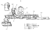
図1は本発明の実施の形態1の空気調和機を示す斜視図、図2は同空気調和機のセンサホルダを示す斜視図、図3は同空気調和機のセンサホルダの分解状態を示す斜視図、図4は同空気調和機のセンサホルダとその表示基板ホルダを示す斜視図、図5は同空気調和機の輻射センサ機器組付体の正面を示す斜視図、図6は同空気調和機の輻射センサ機器組付体の背面を示す斜視図、図7は同空気調和機の輻射センサ機器組付体の上面を示す斜視図、図8は同空気調和機の輻射センサホルダ駆動機構の構成を示す構成図、図9は同空気調和機の輻射センサホルダの取り外し過程を示す説明図である。
1 is a perspective view showing an air conditioner according to
図1において、空気調和機の室内機1の中央部に横に細長いセンサホルダ2が設けられており、そのセンサホルダ2の真ん中に室内の床や壁の温度を測定するための赤外線の輻射センサ3が取り付けられている。また、室内機1の上部に前面パネル4が設けられ、室内機1の下部に空気吹出口5が設けられている。
図2〜図4に示すように、輻射センサ3は輻射センサホルダ6に保持され、その輻射センサホルダ6と輻射センサホルダ6を左右方向に回転駆動させる輻射センサホルダ駆動機構7とが輻射センサ機器組付体8に組み付けられている。
輻射センサ3等を取り付ける横に細長のセンサホルダ2は合成樹脂で形成され、中央に輻射センサ機器組付体8が収容状態に取り付け固定される函状の組付体固定部9を有し、左側に横長の風向・風量表示部10を有し、右側に横長の運転のオン・オフや運転モニタ等の各種表示部11及びリモコン受信部12を有し、さらにリモコン受信部12の右側にこれら表示部10,11やリモコン受信部12に接続されるリード線14を保持する横長のリード線保持部13が設けられている。
In FIG. 1, an
As shown in FIGS. 2 to 4, the
The horizontally
このリード線保持部13はヒンジ構造を有しており、折り返すことによって図2に示すようにリード線14を保持し、室内機1の側方に配置される制御基板(図示せず)に導く。
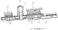
また、風向・風量表示部10と各種表示部11及びリモコン受信部12の一側部には図4に示すように、ヒンジ構造を介して表示基板ホルダ15がそれぞれ設けられている。そして、表示基板ホルダ15を表示部10、11に向けてヒンジ構造部分で折り返すことによってLEDを有する表示基板(図示省略)が表示部10,11とで保持されるように構成されている。
16は組付体固定部9の開口部を覆う組付体固定部カバーである。17は輻射センサホルダ6に保持された輻射センサ3の輻射センサカバーで、輻射センサホルダ6に取り付けられている。
この実施の形態1では、組付体固定部カバー16は組付体固定部9と分離しているが、組付体固定部カバー16が組付体固定部9とヒンジ構造を介して繋がっていてもよいことはいうまでもない。
The lead
Further, as shown in FIG. 4, a
In this
以上のように、本実施の形態1のセンサホルダ2は、組付体固定部9、風向・風量表示部10、各種表示部11、リモコン受信部12及びリード線保持部13が合成樹脂で一体成形して形成され、さらに風向・風量表示部10と各種表示部11及びリモコン受信部12の一側部にヒンジ構造を介して表示基板ホルダ15がそれぞれ設けられ、リード線保持部13はヒンジ構造を有しているので、表示基板ホルダ15を表示部10、11に向けてヒンジ構造部分で折り返すことによってLEDを有する表示基板が表示部10,11とで保持され、リード線保持部13も折り返すことによってリード線14を保持することができ、これら複数の部品を1つのセンサホルダ2で格別の保持部材を用意しなくても簡単に保持することができる。
As described above, in the
次に、センサホルダ2の組付体固定部9に取り付け固定される輻射センサ機器組付体8に組み付けられる輻射センサホルダ6と輻射センサホルダ駆動機構7との構成について図5〜8に基づいて説明する。
図5に示すように、輻射センサ機器組付体8は相対向する2枚の組付板20、20と、2枚の組付板20、20を連結する駆動モータ固定板21と、2枚の組付板20、20の間で相対向するように設けられた一対の輻射センサホルダ枢着板22とで構成されている。
この一対の輻射センサホルダ枢着板22に、内部に輻射センサ3を保持した円筒状で側面が一部開口した輻射センサホルダ6の回転軸線上の上下に設けられた丸いボス23が回転可能に枢着されている。その輻射センサホルダ6の上端側外周の略半周にわたって放射状に突出するよう4つの突起24が設けられている。
Next, the configurations of the
As shown in FIG. 5, the radiation
また、駆動モータ固定板21には駆動モータ18が取り付けられ、駆動モータ18のモータ軸18aは駆動モータ固定板21を貫通している。そのモータ軸18aの向きが輻射センサホルダ6の回転軸線と同じ方向を向いて両者は平行である。
また、モータ軸18aに扇状連結部材25が連結固定されており、扇状連結部材25の外周縁側に3つのピン26が輻射センサホルダ6のある側に向かって突設されている。
そして、扇状連結部材25の3つのピン26が輻射センサホルダ6の4つの突起24の間に各々嵌まり込む構造となっている。
A
A fan-like connecting
Then, the three
従って、輻射センサホルダ駆動機構7は、駆動モータ固定板21に取り付けられた駆動モータ18と、駆動モータ18のモータ軸18aに連結固定された3つのピン26を有する扇状連結部材25と、輻射センサホルダ6の上端側外周に設けられ、3つのピン26が各々嵌まり込むように設けられた4つの突起24とで構成されている。
尚、輻射センサホルダ6に設けられた4つの突起24は、駆動モータ18が回転した際には、扇状連結部材25のピン26が突起24の間に近づいたり離れたりする過程においてピン26と突起24が干渉して駆動モータ18の回転を妨げてしまうことのない形状となっている。
Therefore, the radiation sensor
Note that the four
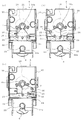
次に、輻射センサホルダ駆動機構7の動作について図8に基づいて説明する。
例えば図8の(a)に示す状態から、駆動モータ18が回転すると、駆動モータ18のモータ軸18aに連結固定された扇状連結部材25も回転し、扇状連結部材25に設けられた3つのピン26が輻射センサホルダ6の上端側外周に設けられ突起24を押すことで、輻射センサホルダ6が図8の(b)又は(c)に示すように左右に回転駆動させられる。
Next, operation | movement of the radiation sensor
For example, when the
以上のように、本実施の形態1の輻射センサホルダ駆動機構7によれば、輻射センサホルダ6の上端側外周に設けられ突起24を、駆動モータ18のモータ軸18aに連結固定された扇状連結部材25に設けられた3つのピン26が押すことで、輻射センサホルダ6が左右に回転駆動させられるため、輻射センサホルダ6の回転軸線上に駆動モータ18のモータ軸18aを設けなくても済み、しかも輻射センサホルダ駆動機構7は駆動モータ18の他には、駆動モータ18のモータ軸18aに連結固定された3つのピン26を有する扇状連結部材25と、輻射センサホルダ6の上端側外周に設けられ、3つのピン26が各々嵌まり込むように設けられた4つの突起24とで構成されているため、部品が簡略化されて組立作業性も容易であり、輻射センサホルダ6と駆動モータ18が離れていても、扇状連結部材25はたわみなどが生ぜず、駆動角度のずれを防止することができる。
As described above, according to the radiation sensor
なお、突起24の数およびピン26の数は、輻射センサホルダ6の回転駆動角度の範囲に応じて適宜調整されるものであって、突起24が4つ、ピン26が3つに拘束されるものでない。
また、輻射センサホルダ駆動機構7を構成する輻射センサホルダ6の上端側外周に設けられ4つの突起24と、駆動モータ18のモータ軸18aに連結固定された3つのピン26を有する扇状連結部材25とを、摺動性の良い材料、例えば自己潤滑性を有する樹脂で形成することにより、輻射センサホルダ6の駆動がよりスムーズになる。
The number of
A fan-like connecting
次に、輻射センサホルダ6の駆動時におけるリード線14の取り回しについて図6及び図7に基づいて説明する。
図6に示すように、輻射センサホルダ6に接続されるリード線14は、駆動モータ18が設けられている位置とは反対側から取り出されており、駆動モータ18の後側から脇を通り駆動モータ18の前側へと取り回されている。駆動モータ18の前側には駆動モータ固定板21上に、リード線14に固定されているバンド28を所定の範囲内で移動可能な状態で保持するためのバンド固定部29が設けられている。
従って、輻射センサホルダ6に接続されるリード線14が駆動モータ18の後側から脇を通り駆動モータ18の前側へと取り回されているので、モータ軸18aに連結固定された扇状連結部材25のピン26や輻射センサホルダ6の上端側外周に設けられた突起24に触れて引っ張られることが無く、輻射センサホルダ6がスムーズに回転駆動することができる。
Next, the handling of the
As shown in FIG. 6, the
Accordingly, since the
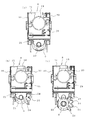
次に、輻射センサホルダ6の回転軸線上の上下に設けられた丸いボス23が一対の輻射センサホルダ枢着板22、22に回転可能に枢着されている構成について図9に基づいて詳細に説明する。
輻射センサホルダ6のボス23が回転可能に枢着される輻射センサホルダ枢着板22には一部がカットされた円形の枢着穴22aが設けられている。
また、輻射センサホルダ6の丸いボス23は、輻射センサホルダ枢着板22の枢着穴22aの径より少し小さい口径で、相対向する周縁が平行にカットされた形状になっている。そして、ボス23のカットされて残された部分の幅は、枢着穴22aのカットされた部分に入り込むように、枢着穴22aのカットされた部分の幅よりも少し小さく形成されている。
Next, a configuration in which
The radiation sensor
The
従って、輻射センサホルダ枢着板22の枢着穴22aのカットされた部分から枢着穴22a内に輻射センサホルダ6のボス23のカットされた部分を挿入し、輻射センサホルダ6を90度回転させれば、ボス23の丸の口径が枢着穴22aのカットされた部分の幅より大きいために枢着穴22a内にボス23が回転可能に枢着される。
この状態の時に輻射センサホルダ6が正面を向くように設定し、輻射センサホルダ6が所定の駆動角度で回転している場合には、枢着穴22aからボス23が外れることはないが、所定の駆動角度を越えて真横を向いた、即ち90度回転した場合にはボス23のカットされた部分の口径が枢着穴22aのカットされた部分の幅より小さいためにボス23のカットされた部分が枢着穴22aのカットされた部分から抜け出て輻射センサホルダ6が輻射センサホルダ枢着板22の枢着穴22aから外れることとなる。
従って、輻射センサホルダ6が90度以内で回転した場合には輻射センサホルダ6のボス23が輻射センサホルダ枢着板22の枢着穴22aから外れることはない。
Therefore, the cut portion of the
In this state, when the
Therefore, when the
以上のように、輻射センサホルダ6のボス23の輻射センサホルダ枢着板22への枢着を、輻射センサホルダ枢着板22の枢着穴22aを一部カットし、輻射センサホルダ6の丸いボス23の上下をカットしただけで行うことができ、別部品を用意する必要が無いため、部品点数を大幅に削減することができ、しかも輻射センサホルダ枢着板22の枢着穴22aへの輻射センサホルダ6のボス23の枢着も工具を用いることなく容易に行うことができる。
As described above, the
図10は同空気調和機の室内機の内部構造を示す断面図、図11は同空気調和機の室内機の内部構造の一部を拡大した断面図である。
図10、図11に示すように、空気調和機の室内機1は、前面パネル4を有する筐体31の内部に、送風機32とこの送風機32を囲むように多段に折り曲げられて送風機32の前面及び背面に設置される冷凍サイクルの熱交換器33とを備えている。
送風機32を回転させることにより、室内の空気は、上面の吸込口34から空気調和機の室内機1の内部に入り、熱交換器33の上流側に設置されたフィルタ35にて塵埃などが除去された後で熱交換器33に導かれ、ここで冷凍サイクルの冷媒と熱交換する。
熱交換された後の室内の空気は調和空気となって、送風機32の下流側で筐体31によって形成される風路36を通って空気吹出口5へと送風され、風向偏向装置37により風向が調整されて室内へと吹き出される。
また、熱交換器33と吸込口34との間には、吸込口34から吸い込まれた室内の空気に含まれる塵埃を帯電させてフィルタ35で捕集させ易くするとともに、オゾンを生成して熱交換器33を殺菌、清浄するプラズマ発生装置38及びプラズマ発生装置38に電源を供給する電源箱39が設けられている。
FIG. 10 is a cross-sectional view showing the internal structure of the indoor unit of the air conditioner, and FIG. 11 is an enlarged cross-sectional view of a part of the internal structure of the indoor unit of the air conditioner.
As shown in FIGS. 10 and 11, the
By rotating the
The indoor air after the heat exchange is conditioned air and is blown to the
In addition, between the
このような空気調和機の室内機1の中央部で前面パネル4の内側にセンサホルダ2が取り付けられている。そのセンサホルダ2の真ん中の組付体固定部9に輻射センサ機器組付体8が取り付け固定されている。この輻射センサ機器組付体8に輻射センサ3を保持した輻射センサホルダ6と、輻射センサホルダ6を回転駆動する輻射センサホルダ駆動機構7とが組み付けられている。
The
図10、図11に示すように構成された輻射センサホルダ駆動機構7によれば、輻射センサホルダ6の上端側外周に設けられ突起24を、駆動モータ18のモータ軸18aに連結固定された扇状連結部材25に設けられた3つのピン26が押すことで、輻射センサホルダ6が左右に回転駆動させられるため、輻射センサホルダ6の回転軸線上に駆動モータ18のモータ軸18を設けなくても済み、前面パネル4の内側で、かつ輻射センサホルダ6の上部の位置で輻射センサホルダ6の回転軸線より内側に駆動モータ18を位置させることができる。そのため、輻射センサホルダ6および輻射センサホルダ駆動機構7を室内機1の中央に配置することが可能となり、室内の広い範囲の床面温度を検出することができるとともに、室内機1の外観の意匠性も向上する。
According to the radiation sensor
1 室内機、2 センサホルダ、3 輻射センサ、4 前面パネル、5 空気吹出口、6 輻射センサホルダ、7 輻射センサホルダ駆動機構、8 輻射センサ機器組立体、9 組付体固定部、10 風向・風量表示部、12 リモコン受信部、13 リード線保持部、14 リード線、15 表示基板ホルダ、16 組付体固定部カバー、17 輻射センサカバー、18 駆動モータ、18a モータ軸、20 組付板、21 駆動モータ固定板、22 輻射センサホルダ枢着板、22a 枢着穴、23 ボス、24 突起、25 扇状連結部材、26 ピン。 1 indoor unit, 2 sensor holder, 3 radiation sensor, 4 front panel, 5 air outlet, 6 radiation sensor holder, 7 radiation sensor holder drive mechanism, 8 radiation sensor equipment assembly, 9 assembly fixing part, 10 wind direction / Air volume display unit, 12 Remote control receiving unit, 13 Lead wire holding unit, 14 Lead wire, 15 Display substrate holder, 16 Assembly fixing unit cover, 17 Radiation sensor cover, 18 Drive motor, 18a Motor shaft, 20 Assembly plate, 21 drive motor fixing plate, 22 radiation sensor holder pivoting plate, 22a pivoting hole, 23 boss, 24 projection, 25 fan-shaped connecting member, 26 pin.
Claims (3)
前記室内機の前面パネルの内側に輻射センサ機器組付体を設け、該輻射センサ機器組付体に前記輻射センサホルダと該輻射センサホルダを回転させる輻射センサホルダ駆動機構を組み付け、
該輻射センサホルダ駆動機構は、前記輻射センサホルダの外周の一部に放射状に突出するように設けられた複数の突起と、前記輻射センサ機器組付体に、モータ軸の向きが前記輻射センサホルダの回転軸線と同じ方向になるように取り付けられた駆動モータと、該駆動モータのモータ軸に連結固定され、前記輻射センサホルダに設けられた複数の突起の間に嵌り込むピンを有する扇状連結部材を備え、
前記輻射センサ機器組付体に設けられた一対の輻射センサホルダ枢着板にそれぞれ一部がカットされた枢着穴を設け、該枢着穴に枢着される丸いボスを前記輻射センサホルダの上下の回転軸線上に設け、該ボスの相対向する周縁を平行にカットし、カットされて残された部分の幅を前記枢着穴のカットされた部分に入り込むように該枢着穴のカットされた部分の幅より少し小さく形成し、
前記駆動モータの回転により前記扇状連結部材が回転し、前記扇状連結部材のピンが前記突起を押すことで前記輻射センサホルダは前記ボスが枢着された前記枢着穴を中心に左右に回転し、
前記輻射センサホルダが前記駆動モータの回転により所定の駆動角度以内で回転している状態においては、前記ボスは、該ボスのカットされていない部分の周縁が前記枢着穴に支持され、
前記センサホルダを前記所定の駆動角度を超えて回転させた状態においては、前記ボスのカットされて残された部分が前記枢着穴のカットされた部分を通過可能となって、前記輻射センサホルダが輻射センサホルダ枢着板に着脱自在となることを特徴とする空気調和機。 An air conditioner having a radiation sensor holder that holds a radiation sensor that detects temperature and rotates left and right in an indoor unit,
A radiation sensor device assembly is provided inside the front panel of the indoor unit, and the radiation sensor holder and a radiation sensor holder driving mechanism for rotating the radiation sensor holder are assembled to the radiation sensor device assembly,
The radiation sensor holder driving mechanism includes a plurality of protrusions provided radially projecting from a part of an outer periphery of the radiation sensor holder, and the radiation sensor device assembly, wherein the direction of the motor shaft is the radiation sensor holder. A fan-shaped connecting member having a drive motor attached so as to be in the same direction as the rotation axis of the motor, and a pin that is connected and fixed to the motor shaft of the drive motor and fits between a plurality of protrusions provided on the radiation sensor holder With
A pair of radiation sensor holder pivot plates provided in the radiation sensor device assembly are provided with pivot holes that are partially cut, and round bosses pivoted to the pivot holes are provided on the radiation sensor holder. provided above and below the axis of rotation, cut parallel to the peripheral edge facing each of said boss, cut該枢Chakuana so as to enter the width of the remaining portion is cut in the cut portion of said pivot hole Forming a little smaller than the width of the part,
The fan-shaped connecting member is rotated by the rotation of the drive motor, the radiant sensor holder in the pin of the fan-shaped connecting member pushes said projection rotates to the right and left about the pivot hole in which the boss is pivotally mounted ,
In the state where the radiation sensor holder is rotated within a predetermined driving angle by the rotation of the drive motor, the boss is supported by the pivot hole at the periphery of the uncut portion of the boss,
In a state where the sensor holder is rotated beyond the predetermined drive angle, the portion left after the boss is cut can pass through the portion where the pivot hole is cut, and the radiation sensor holder The air conditioner is characterized in that it is detachable from the radiation sensor holder pivot plate .
Priority Applications (4)
| Application Number | Priority Date | Filing Date | Title |
|---|---|---|---|
| JP2007223993A JP4537433B2 (en) | 2007-08-30 | 2007-08-30 | Air conditioner |
| US11/987,875 US7810739B2 (en) | 2007-08-30 | 2007-12-05 | Air conditioner |
| ES07023762T ES2391984T3 (en) | 2007-08-30 | 2007-12-07 | Air conditioner |
| EP07023762A EP2031316B1 (en) | 2007-08-30 | 2007-12-07 | Air conditioner |
Applications Claiming Priority (1)
| Application Number | Priority Date | Filing Date | Title |
|---|---|---|---|
| JP2007223993A JP4537433B2 (en) | 2007-08-30 | 2007-08-30 | Air conditioner |
Publications (3)
| Publication Number | Publication Date |
|---|---|
| JP2009058145A JP2009058145A (en) | 2009-03-19 |
| JP2009058145A5 JP2009058145A5 (en) | 2009-07-02 |
| JP4537433B2 true JP4537433B2 (en) | 2010-09-01 |
Family
ID=39831669
Family Applications (1)
| Application Number | Title | Priority Date | Filing Date |
|---|---|---|---|
| JP2007223993A Expired - Fee Related JP4537433B2 (en) | 2007-08-30 | 2007-08-30 | Air conditioner |
Country Status (4)
| Country | Link |
|---|---|
| US (1) | US7810739B2 (en) |
| EP (1) | EP2031316B1 (en) |
| JP (1) | JP4537433B2 (en) |
| ES (1) | ES2391984T3 (en) |
Families Citing this family (15)
| Publication number | Priority date | Publication date | Assignee | Title |
|---|---|---|---|---|
| TWI396817B (en) * | 2007-09-20 | 2013-05-21 | Asustek Comp Inc | Air conditioner |
| KR101507163B1 (en) * | 2008-11-10 | 2015-03-30 | 엘지전자 주식회사 | Indoor unit for air conditioning apparatus |
| JP5173957B2 (en) * | 2009-07-29 | 2013-04-03 | 三菱電機株式会社 | Air conditioner indoor unit |
| JP5147809B2 (en) * | 2009-10-22 | 2013-02-20 | 三菱電機株式会社 | Air conditioner |
| JP5334929B2 (en) * | 2010-08-06 | 2013-11-06 | 三菱電機株式会社 | Air conditioner indoor unit |
| JP5199410B2 (en) * | 2011-02-17 | 2013-05-15 | シャープ株式会社 | Air conditioner |
| JP6138001B2 (en) * | 2013-09-06 | 2017-05-31 | ジョンソンコントロールズ ヒタチ エア コンディショニング テクノロジー(ホンコン)リミテッド | Indoor unit of air conditioner and air conditioner using the same |
| JP6274995B2 (en) * | 2014-07-23 | 2018-02-07 | 三菱電機株式会社 | Reciprocating rotary sensor and air conditioner indoor unit equipped with the same |
| US10746434B2 (en) | 2015-07-30 | 2020-08-18 | Mitsubishi Electric Corporation | Housing cover and indoor unit of air conditioning apparatus having the housing cover |
| JP6531282B2 (en) * | 2016-02-01 | 2019-06-19 | パナソニックIpマネジメント株式会社 | Air conditioner |
| CN106595008B (en) * | 2016-12-09 | 2020-02-11 | 青岛海信日立空调系统有限公司 | Mounting device of human body inductor and air conditioner |
| CN108131725B (en) * | 2017-12-05 | 2020-11-13 | 广东美的暖通设备有限公司 | Shell assembly of air conditioner and air conditioner with shell assembly |
| CN111486583B (en) * | 2019-01-25 | 2022-01-04 | 苏州三星电子有限公司 | Air conditioner panel and air conditioner |
| CN210769402U (en) * | 2019-08-01 | 2020-06-16 | 广东美的环境电器制造有限公司 | Wind wheel device and blowing equipment |
| CN112484241A (en) * | 2020-11-02 | 2021-03-12 | 珠海格力电器股份有限公司 | Cleaning method and device for air conditioner |
Citations (6)
| Publication number | Priority date | Publication date | Assignee | Title |
|---|---|---|---|---|
| JPH06105236A (en) * | 1992-09-17 | 1994-04-15 | Matsushita Electric Ind Co Ltd | Thermal picture detector |
| JPH06105882A (en) * | 1992-09-18 | 1994-04-19 | Alpha Corp:Kk | Oscillation device of jet water nozzle |
| JPH0894118A (en) * | 1994-09-29 | 1996-04-12 | Toshiba Corp | Indoor unit |
| JPH0972781A (en) * | 1995-09-07 | 1997-03-18 | Matsushita Electric Ind Co Ltd | Infrared sensor |
| JPH1154962A (en) * | 1997-08-05 | 1999-02-26 | Mitsubishi Electric Corp | Substrate holder of electrical apparatus |
| JP2003262359A (en) * | 2002-03-07 | 2003-09-19 | Mitsubishi Electric Corp | Dehumidifier |
Family Cites Families (12)
| Publication number | Priority date | Publication date | Assignee | Title |
|---|---|---|---|---|
| JPS61149751A (en) * | 1984-12-24 | 1986-07-08 | Toshiba Corp | Air conditioner |
| JPH0486447A (en) | 1990-07-31 | 1992-03-19 | Daikin Ind Ltd | Driving device for infra-red ray sensor |
| JPH05231728A (en) * | 1992-02-24 | 1993-09-07 | Toshiba Corp | Air conditioner |
| JP2925897B2 (en) | 1993-08-23 | 1999-07-28 | 三洋電機株式会社 | Air conditioner |
| US5381950A (en) * | 1993-10-20 | 1995-01-17 | American Standard Inc. | Zone sensor or thermostat with forced air |
| KR20010011429A (en) * | 1999-07-28 | 2001-02-15 | 윤종용 | A fixing apparatus of temperature sensor for air conditioner |
| JP4288778B2 (en) | 1999-08-20 | 2009-07-01 | 株式会社富士通ゼネラル | Air conditioner |
| JP3735592B2 (en) * | 2001-06-19 | 2006-01-18 | エルジー電子株式会社 | Air conditioner |
| JP2003074952A (en) | 2001-08-28 | 2003-03-12 | Toshiba Kyaria Kk | Air conditioner |
| JP3842125B2 (en) | 2001-12-21 | 2006-11-08 | トヨタ車体株式会社 | Air conditioner |
| US6892551B2 (en) * | 2002-09-26 | 2005-05-17 | Fujitsu General Limited | Air conditioner |
| JP4537903B2 (en) | 2005-07-25 | 2010-09-08 | 三菱電機株式会社 | Air conditioner |
-
2007
- 2007-08-30 JP JP2007223993A patent/JP4537433B2/en not_active Expired - Fee Related
- 2007-12-05 US US11/987,875 patent/US7810739B2/en not_active Expired - Fee Related
- 2007-12-07 ES ES07023762T patent/ES2391984T3/en active Active
- 2007-12-07 EP EP07023762A patent/EP2031316B1/en not_active Expired - Fee Related
Patent Citations (6)
| Publication number | Priority date | Publication date | Assignee | Title |
|---|---|---|---|---|
| JPH06105236A (en) * | 1992-09-17 | 1994-04-15 | Matsushita Electric Ind Co Ltd | Thermal picture detector |
| JPH06105882A (en) * | 1992-09-18 | 1994-04-19 | Alpha Corp:Kk | Oscillation device of jet water nozzle |
| JPH0894118A (en) * | 1994-09-29 | 1996-04-12 | Toshiba Corp | Indoor unit |
| JPH0972781A (en) * | 1995-09-07 | 1997-03-18 | Matsushita Electric Ind Co Ltd | Infrared sensor |
| JPH1154962A (en) * | 1997-08-05 | 1999-02-26 | Mitsubishi Electric Corp | Substrate holder of electrical apparatus |
| JP2003262359A (en) * | 2002-03-07 | 2003-09-19 | Mitsubishi Electric Corp | Dehumidifier |
Also Published As
| Publication number | Publication date |
|---|---|
| ES2391984T3 (en) | 2012-12-03 |
| JP2009058145A (en) | 2009-03-19 |
| US20090057432A1 (en) | 2009-03-05 |
| EP2031316A3 (en) | 2009-03-25 |
| EP2031316B1 (en) | 2012-09-12 |
| EP2031316A2 (en) | 2009-03-04 |
| US7810739B2 (en) | 2010-10-12 |
Similar Documents
| Publication | Publication Date | Title |
|---|---|---|
| JP4537433B2 (en) | Air conditioner | |
| EP3040627B1 (en) | Air conditioner | |
| JP4110863B2 (en) | Air conditioner | |
| KR100904510B1 (en) | Indoor unit of air conditioner | |
| CN108369138B (en) | Sensor unit and indoor unit of air conditioner provided with same | |
| WO2015080165A1 (en) | Indoor unit | |
| JP2017026256A (en) | Air conditioner | |
| KR101611327B1 (en) | Stand type air conditioner | |
| KR20070045043A (en) | Indoor unit for air conditioner | |
| JP6081346B2 (en) | Indoor unit | |
| JPH1114134A (en) | Indoor machine of air conditioner | |
| KR101315604B1 (en) | Indoor unit for air conditioner | |
| KR101529223B1 (en) | Air conditioner and Control method of the same | |
| JP6331935B2 (en) | Embedded ceiling air conditioner | |
| JP6032413B2 (en) | Air conditioner | |
| JP5765313B2 (en) | Air conditioning indoor unit | |
| JP2005164075A (en) | Air conditioning system | |
| JP6020810B2 (en) | Air conditioner | |
| JP6058522B2 (en) | Indoor unit | |
| JP5790754B2 (en) | Indoor unit | |
| JP2012042181A (en) | Indoor unit of air conditioner | |
| KR101529224B1 (en) | Air conditioner and Control method of the same | |
| JP7246911B2 (en) | air conditioner | |
| JP6281676B2 (en) | Air conditioner | |
| JP4194925B2 (en) | Air conditioner |
Legal Events
| Date | Code | Title | Description |
|---|---|---|---|
| A521 | Request for written amendment filed |
Free format text: JAPANESE INTERMEDIATE CODE: A523 Effective date: 20090518 |
|
| A621 | Written request for application examination |
Free format text: JAPANESE INTERMEDIATE CODE: A621 Effective date: 20090518 |
|
| A977 | Report on retrieval |
Free format text: JAPANESE INTERMEDIATE CODE: A971007 Effective date: 20091005 |
|
| A131 | Notification of reasons for refusal |
Free format text: JAPANESE INTERMEDIATE CODE: A131 Effective date: 20091020 |
|
| A521 | Request for written amendment filed |
Free format text: JAPANESE INTERMEDIATE CODE: A523 Effective date: 20091119 |
|
| A131 | Notification of reasons for refusal |
Free format text: JAPANESE INTERMEDIATE CODE: A131 Effective date: 20100302 |
|
| A521 | Request for written amendment filed |
Free format text: JAPANESE INTERMEDIATE CODE: A523 Effective date: 20100423 |
|
| TRDD | Decision of grant or rejection written | ||
| A01 | Written decision to grant a patent or to grant a registration (utility model) |
Free format text: JAPANESE INTERMEDIATE CODE: A01 Effective date: 20100601 |
|
| A01 | Written decision to grant a patent or to grant a registration (utility model) |
Free format text: JAPANESE INTERMEDIATE CODE: A01 |
|
| A61 | First payment of annual fees (during grant procedure) |
Free format text: JAPANESE INTERMEDIATE CODE: A61 Effective date: 20100617 |
|
| FPAY | Renewal fee payment (event date is renewal date of database) |
Free format text: PAYMENT UNTIL: 20130625 Year of fee payment: 3 |
|
| R150 | Certificate of patent or registration of utility model |
Ref document number: 4537433 Country of ref document: JP Free format text: JAPANESE INTERMEDIATE CODE: R150 Free format text: JAPANESE INTERMEDIATE CODE: R150 |
|
| R250 | Receipt of annual fees |
Free format text: JAPANESE INTERMEDIATE CODE: R250 |
|
| R250 | Receipt of annual fees |
Free format text: JAPANESE INTERMEDIATE CODE: R250 |
|
| R250 | Receipt of annual fees |
Free format text: JAPANESE INTERMEDIATE CODE: R250 |
|
| LAPS | Cancellation because of no payment of annual fees |