JP5159068B2 - Total reflection X-ray fluorescence analyzer - Google Patents
Total reflection X-ray fluorescence analyzer Download PDFInfo
- Publication number
- JP5159068B2 JP5159068B2 JP2006231713A JP2006231713A JP5159068B2 JP 5159068 B2 JP5159068 B2 JP 5159068B2 JP 2006231713 A JP2006231713 A JP 2006231713A JP 2006231713 A JP2006231713 A JP 2006231713A JP 5159068 B2 JP5159068 B2 JP 5159068B2
- Authority
- JP
- Japan
- Prior art keywords
- ray
- sample
- rays
- polycapillary
- primary
- Prior art date
- Legal status (The legal status is an assumption and is not a legal conclusion. Google has not performed a legal analysis and makes no representation as to the accuracy of the status listed.)
- Expired - Fee Related
Links
Images


Description
本発明は、1次X線を試料表面に向かって全反射する入射角度で入射して、試料表面から発生する蛍光X線を分析する全反射蛍光X線分析装置に関するものである。 The present invention is incident primary X-rays at an incident angle of total reflection towards the sample surface, to a total reflection X-ray fluorescence analyzer for analyzing the fluorescent X-ray generated from the sample surface.
蛍光X線分析装置を用いて測定の検出限界を良くするためには、試料に入射する1次X線強度を上げるだけでなく、バックグラウンドを下げることも必要である。
全反射蛍光X線分析方法はシリコンウエハのような平坦な試料表面で1次X線を全反射させ、試料表面に対向させて検出器を配置し、1次X線を受けて測定対象としての試料表面の微小領域又は試料表面上についた不純物から発生する蛍光X線を検出することにより、1次X線の散乱に起因する連続X線バックグラウンドを軽減して蛍光X線を高感度に測定する方法である。
In order to improve the detection limit of measurement using a fluorescent X-ray analyzer, it is necessary not only to increase the primary X-ray intensity incident on the sample but also to lower the background.
In the total reflection X-ray fluorescence analysis method, primary X-rays are totally reflected on a flat sample surface such as a silicon wafer, a detector is placed facing the sample surface, and the primary X-rays are received as a measurement target. Measures X-ray fluorescence with high sensitivity by detecting continuous X-ray background caused by scattering of primary X-rays by detecting X-ray fluorescence generated from impurities on the sample surface or on the sample surface. It is a method to do.
通常、1次X線としては幅1cm程度、厚さ数十μmから数百μmのシート状のX線ビームを用い、試料表面に対して0.1度程度の非常に浅い角度で照射する。よって、試料表面のかなり広い範囲を照射していることになる。 Usually, as the primary X-ray, a sheet-like X-ray beam having a width of about 1 cm and a thickness of several tens to several hundreds of μm is used, and the sample surface is irradiated at a very shallow angle of about 0.1 degree. Therefore, a considerably wide range of the sample surface is irradiated.
試料表面自身も大面積を有しているので、1次X線により広範囲を照射し広範囲の蛍光X線分析を行う点は望ましいとも言える。しかし、近年はシリコンウエハ上に存在する微粒子の不純物分析というような微小領域の分析に対する需要が高まっている。 Since the sample surface itself also has a large area, it can be said that it is desirable to perform a wide range of fluorescent X-ray analysis by irradiating a wide range with primary X-rays. However, in recent years, there has been an increasing demand for analysis of minute regions such as impurity analysis of fine particles existing on a silicon wafer.
そのような微小領域の分析において、例えば微粒子の直径は数μm以下であるため、もはやシリコンウエハ表面の広範囲を1次X線で照射する必要はなくなる。1次X線としてシート状のX線ビームを使用する場合には、微粒子に対して集光能力はなく、むしろ、測定対象の微粒子以外の箇所にも1次X線が照射されることによって微粒子自身の分析を困難にしてしまう。このことは、高輝度のX線源を使用して1次X線の強度を上げても解決はしない。よって、分析箇所である微小領域での1次X線の輝度を選択的に高める工夫が必要とされている。 In the analysis of such a minute region, for example, since the diameter of the fine particles is several μm or less, it is no longer necessary to irradiate a wide area of the silicon wafer surface with primary X-rays. When a sheet-like X-ray beam is used as the primary X-ray, there is no light condensing ability with respect to the fine particles. Rather, the fine particles are irradiated by irradiating the primary X-rays to places other than the fine particles to be measured. It makes my analysis difficult. This cannot be solved even if the intensity of the primary X-ray is increased by using a high-intensity X-ray source. Therefore, a device for selectively increasing the luminance of primary X-rays in a minute region that is an analysis location is required.
全反射蛍光X線分析の利点を生かしつつ、高輝度のX線を用いることなく高い分析精度を得ることを目的として、1次X線を分析箇所に集光し微小領域からの蛍光X線発生強度を増大させる試みとして、分光結晶からなる複数の分光素子を用いて異なる光路から1次X線を集光させるようにした全反射蛍光X線分析装置が提案されている(特許文献1参照。)。
分光素子を用いて1次X線を集光させる方法は、分光することにより1次X線強度が低下してしまうだけでなく、複数の分光結晶を所定の位置と方向に配置するための高精度で大型の機構を必要とする。 The method of condensing primary X-rays using a spectroscopic element not only reduces the primary X-ray intensity by spectroscopic analysis but also a high level for arranging a plurality of spectral crystals in a predetermined position and direction. Requires a large mechanism with precision.
また、生体物質や環境物質を計測する分野では、微量の試料を扱う必要から微小流路を用いた送液や反応を行なうことのできるマイクロチップを用いたマイクロチップ分析と呼ばれる方法が試みられている。マイクロチップ分析での検出方法として全反射蛍光X線分析を応用することが考えられる。その場合、極めて微量の物質計測が要求されるとともに、小型簡便な構造であることが必須条件となる。特にX線光源の小型化は安全性の点でも必須である。 In the field of measuring biological substances and environmental substances, a method called microchip analysis using a microchip capable of performing liquid feeding and reaction using a micro flow channel has been attempted because it is necessary to handle a small amount of sample. Yes. It is conceivable to apply total reflection X-ray fluorescence analysis as a detection method in microchip analysis. In that case, measurement of a very small amount of substance is required, and a small and simple structure is an essential condition. In particular, miniaturization of the X-ray light source is essential from the viewpoint of safety.
本発明は、試料表面上の微粒子に限らず、試料の微小領域を分析することを対象にし、全反射蛍光X線分析の利点を生かしつつ、X線源から照射される1次X線の強度を低下させることなく1次X線を試料の微小領域に集光させることができるようにして、測定対象からの蛍光X線発生強度を高めて高感度な全反射蛍光X線分析を行なうことのできる装置を提供することを目的とするものである。 The present invention is not limited to fine particles on a sample surface, and is intended for analyzing a micro area of a sample. The intensity of primary X-rays irradiated from an X-ray source while taking advantage of total reflection X-ray fluorescence analysis. The primary X-ray can be focused on a minute region of the sample without lowering the intensity, and the high-sensitivity total reflection X-ray fluorescence analysis can be performed by increasing the intensity of fluorescent X-ray generation from the measurement object. An object of the present invention is to provide a device that can be used .
本発明の全反射蛍光X線分析方法は、試料表面に照射する1次X線を、ポリキャピラリーX線レンズを用いて集光させる点に特徴がある。 The total reflection X-ray fluorescence analysis method of the present invention is characterized in that primary X-rays irradiated on a sample surface are condensed using a polycapillary X-ray lens.
好ましくは、ポリキャピラリーX線レンズから出射する1次X線は、その進行方向に対して直交する方向の断面形状が線状であるようにする。 Preferably, the primary X-ray emitted from the polycapillary X-ray lens has a linear cross-sectional shape in a direction orthogonal to the traveling direction.
より好ましくは、試料表面に照射する1次X線のうち、試料表面に対して全反射条件を満たさない入射角をもつ1次X線を遮蔽する。 More preferably, among the primary X-rays irradiated to the sample surface, the primary X-ray having an incident angle that does not satisfy the total reflection condition with respect to the sample surface is shielded.
この全反射蛍光X線分析方法を実現する本発明の全反射蛍光X線分析装置は、試料を載置する試料台と、1次X線を発生するX線源及びその1次X線を集光して試料台上に載置された試料に照射するポリキャピラリーX線レンズを含み、その1次X線を試料の表面に対し全反射を起こす入射角で入射させる1次X線照射部と、試料台上に載置された試料の表面に対向して配置され、試料から発生する蛍光X線を検出する検出器とを備えている。 The total reflection X-ray fluorescence analyzer of the present invention that realizes this total reflection X-ray fluorescence analysis method collects a sample stage on which a sample is placed, an X-ray source that generates primary X-rays, and the primary X-rays. A primary X-ray irradiator that includes a polycapillary X-ray lens that irradiates and irradiates a sample placed on the sample stage, and that makes the primary X-ray incident at an incident angle that causes total reflection on the surface of the sample; And a detector that is arranged to face the surface of the sample placed on the sample stage and detects fluorescent X-rays generated from the sample.
ポリキャピラリーX線レンズは、その中をX線が全反射して伝わる細いガラス管(モノキャピラリー)が多数束ねられたものであり、キャピラリーを緩やかに曲げることによりX線の軌道を曲げ、キャピラリーから出射するX線が1点に集中するように形成されたものである。各モノキャピラリーはその内径が受光部側の基端から放射側の先端にかけていったん拡大し、先端に向かって漸次細くなる形状をもっている。ポリキャピラリーX線レンズは全反射によりX線の軌道を曲げ、分光を伴わないため、分光結晶を用いた分光素子のようなX線強度の減衰はない。 A polycapillary X-ray lens is a bundle of many thin glass tubes (monocapillaries) through which X-rays are totally reflected and bent, and the X-ray trajectory is bent by gently bending the capillary. The emitted X-rays are formed so as to be concentrated at one point. Each monocapillary has a shape in which the inner diameter once expands from the proximal end on the light receiving portion side to the distal end on the radiation side and gradually becomes thinner toward the distal end. Since the polycapillary X-ray lens bends the X-ray trajectory by total reflection and does not accompany spectroscopy, there is no attenuation of X-ray intensity unlike a spectroscopic element using a spectroscopic crystal.
より好ましくは、ポリキャピラリーX線レンズの構成を最適化して、分析精度の向上とエックス線光源部の小型化を図るために、ポリキャピラリーX線レンズから出射する1次X線が進行方向に対して直交する方向の断面形状が試料表面に平行な線状となるようにする。そのために、ポリキャピラリーX線レンズは、X線光源に対面する入射面ではモノキャピラリーの端部が円形面状に配列され、試料に対面する出射面ではモノキャピラリーの端部が試料表面に平行な線状に、かつ放射方向が一点に向かって集光するように配列されているものとする。その集光点の位置に試料が配置される。 More preferably, in order to optimize the configuration of the polycapillary X-ray lens to improve analysis accuracy and reduce the size of the X-ray light source unit, the primary X-rays emitted from the polycapillary X-ray lens with respect to the traveling direction The cross-sectional shape in the orthogonal direction is a line parallel to the sample surface. Therefore, in the polycapillary X-ray lens, the end of the monocapillary is arranged in a circular shape on the entrance surface facing the X-ray light source, and the end of the monocapillary is parallel to the sample surface on the exit surface facing the sample. It is assumed that they are arranged in a linear manner so that the radiation direction is condensed toward one point. A sample is placed at the position of the condensing point.
全反射蛍光X線分析装置のより好ましい形態では、1次X線照射部は、ポリキャピラリーX線レンズの出射側と試料台との間にスリットを備え、そのスリットは試料台上に載置された試料の表面に対して全反射条件を満たさない入射角をもつ1次X線を遮蔽するように配置されている。 In a more preferred form of the total reflection X-ray fluorescence analyzer, the primary X-ray irradiator is provided with a slit between the exit side of the polycapillary X-ray lens and the sample table, and the slit is placed on the sample table. The primary X-ray having an incident angle that does not satisfy the total reflection condition is shielded from the surface of the sample.
ここで、「スリット」の語は、一般には細長い開口を意味するが、本発明では全反射条件を満たさない入射角をもつ1次X線、すなわち全反射臨界角より大きい入射角をもつ1次X線を遮蔽することができればよいので、細長い開口に限らず、全反射臨界角より大きい入射角側の1次X線のみを遮蔽する遮蔽板も含む概念として使用している。 Here, the term “slit” generally means an elongated opening, but in the present invention, primary X-rays having an incident angle that does not satisfy the total reflection condition, that is, a primary having an incident angle larger than the total reflection critical angle. Since X-rays only need to be shielded, the concept is not limited to an elongated opening, but includes a shielding plate that shields only primary X-rays on the incident angle side larger than the total reflection critical angle.
スリットで測定に適した角度以外のX線を遮断する場合、遮断しすぎるとX線強度が極端に弱くなり、蛍光も微弱となる。X線強度が弱くなるのを補うために過大なX線源を用いると分析装置が大型になる。一方、スリットを広げて広い角度で試料に照射すると測定しようとする試料以外の部分からの1次X線や蛍光X線がノイズとしてでるため分析精度が低下する。 When the X-ray other than the angle suitable for measurement is blocked by the slit, if the X-ray is blocked too much, the X-ray intensity becomes extremely weak and the fluorescence becomes weak. If an excessive X-ray source is used to compensate for the weak X-ray intensity, the analyzer becomes large. On the other hand, if the slit is widened and the sample is irradiated at a wide angle, the primary X-rays and fluorescent X-rays from the part other than the sample to be measured appear as noise, so that the analysis accuracy decreases.
そこで、ポリキャピラリーX線レンズから出射する1次X線が進行方向に対して直交する方向の断面形状が試料表面に平行な線状となるようにする好ましい形態では、スリットを用いなくても測定に適した角度以外のX線が出射されないようにすることができればスリットを設けないようにして、スリットによりX線強度が弱くなる問題を避けることができる。スリットを用いるとしても、スリットの形状に沿った線状に集光させることにより、スリットにより遮断されるX線の割合は少なくてすむ。この形態では、スリットの有無にかかわらずX線強度が大幅に弱くなる問題を避けることができるので、過大なX線源を用いる必要がなくなる。 Therefore, in a preferred mode in which the cross-sectional shape of the primary X-ray emitted from the polycapillary X-ray lens is a line parallel to the sample surface in the direction orthogonal to the traveling direction, measurement is performed without using a slit. If it is possible to prevent X-rays with angles other than those suitable for the beam from being emitted, it is possible to avoid the problem that the X-ray intensity is weakened by the slits by not providing the slits. Even if a slit is used, the ratio of X-rays blocked by the slit can be reduced by condensing light into a line along the shape of the slit. In this embodiment, it is possible to avoid the problem that the X-ray intensity is significantly weak regardless of the presence or absence of the slit, so that it is not necessary to use an excessive X-ray source.
試料台はその上に載置された試料の表面の水平面内方向、高さ方向及び入射X線に対するその試料の表面の傾き方向を調整する調整機構を備えていることが好ましい。
また、試料台上に載置された試料と検出器との間にもポリキャピラリーX線レンズを備えていることが好ましい。
The sample stage is preferably provided with an adjustment mechanism that adjusts the horizontal plane direction, height direction, and tilt direction of the sample surface relative to incident X-rays on the surface of the sample placed thereon.
Further, it is preferable that a polycapillary X-ray lens is also provided between the sample placed on the sample stage and the detector.
通常の全反射蛍光X線分析は1次X線が空間的に集光されることなく広範囲を照射するものであるが、ポリキャピラリーX線レンズを用いた本発明では1次X線の強度を落とすことなく、微粒子などの微小な測定箇所に1次X線を集光させることができる。このように、試料表面での全反射条件を満たしながら集光効果が得られるので、蛍光X線強度が増大し測定感度が向上する。 In general total reflection X-ray fluorescence analysis, primary X-rays irradiate a wide area without being spatially collected. In the present invention using a polycapillary X-ray lens, the intensity of primary X-rays is increased. Primary X-rays can be focused on a minute measurement location such as a fine particle without dropping. As described above, since the light collecting effect is obtained while satisfying the total reflection condition on the sample surface, the fluorescent X-ray intensity is increased and the measurement sensitivity is improved.
試料表面に対して全反射条件を満たさない入射角をもつ1次X線をスリットにより遮蔽するようにすれば、全ての1次X線の試料表面に対する入射角を全反射臨界角以下に保つことができ、バックグラウンドをより少なくして測定限界を向上させることができる。 If the primary X-ray having an incident angle that does not satisfy the total reflection condition with respect to the sample surface is shielded by the slit, the incident angle of all the primary X-rays with respect to the sample surface can be kept below the total reflection critical angle. It is possible to reduce the background and improve the measurement limit.
さらに、ポリキャピラリーX線レンズから出射する1次X線が進行方向に対して直交する方向の断面形状が試料表面に平行な線状となるようにすれば、スリットを設けなくても1次X線の試料表面に対する入射角を全反射臨界角以下に保つことができるようになるので、X線源からポリキャピラリーX線レンズに取り込まれたX線はほぼ全て試料に照射される。さらに角度の均一性は高く、全反射条件がそろうため分析精度はきわめて高いものとなり、微量分析に適した装置となる。また、X線源も相対的に小型化が可能であり、簡便な持ち運びに適した装置を可能とする。 Further, if the cross-sectional shape of the primary X-ray emitted from the polycapillary X-ray lens is a line parallel to the sample surface in the direction orthogonal to the traveling direction, the primary X-ray can be obtained without providing a slit. Since the incident angle of the rays with respect to the sample surface can be kept below the total reflection critical angle, almost all of the X-rays taken into the polycapillary X-ray lens from the X-ray source are irradiated onto the sample. In addition, the uniformity of the angle is high and the total reflection conditions are met, so the analysis accuracy is extremely high, and the apparatus is suitable for microanalysis. In addition, the X-ray source can be relatively miniaturized, and an apparatus suitable for simple carrying is possible.
ポリキャピラリーX線レンズから出射する1次X線が進行方向に対して直交する方向の断面形状が試料表面に平行な線状となるようにした場合にも、スリットを付加すればさらに精度は高くなる。 Even when the cross-sectional shape of the primary X-ray emitted from the polycapillary X-ray lens is a line parallel to the sample surface in the direction perpendicular to the traveling direction, the accuracy can be further improved by adding a slit. Become.
試料と検出器との間にもポリキャピラリーX線レンズを備えれば、試料表面上の微小領域からの蛍光X線のみを検出することができるようになる。 If a polycapillary X-ray lens is provided between the sample and the detector, only fluorescent X-rays from a minute region on the sample surface can be detected.
以下に一実施例を図1、図2及び図3を参照して詳細に説明する。
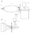
図1は全反射蛍光X線分析装置の全体正面図である。図2と図3はキャピラリーX線レンズ3とスリット5の配置を示す正面断面図と上面断面図であり、それぞれの図において(B)は(A)の鎖線の円で囲った部分の拡大図である。
Hereinafter, an embodiment will be described in detail with reference to FIGS. 1, 2 and 3. FIG.
FIG. 1 is an overall front view of the total reflection X-ray fluorescence spectrometer. 2 and 3 are a front sectional view and a top sectional view showing the arrangement of the
試料台13は試料1を載置するものであり、試料台13に載置された試料1の表面に対し、1次X線を、全反射を起こす入射角で入射させる1次X線照射部2が設けられている。1次X線照射部2は1次X線を発生するX線源3、及びその1次X線を集光して試料1に照射するポリキャピラリーX線レンズ5を備えている。ポリキャピラリーX線レンズ5により1次X線を数十μmのビーム径に集光することができる。
The
ポリキャピラリーX線レンズ5は多数のモノキャピラリーを束ねた構造である。図では個々のモノキャピラリーの図示は省略されている。モノキャピラリーは内径数ミクロンの石英管である。モノキャピラリーはその内径が受光部側の基端から放射側の先端にかけていったん拡大し、先端に向かって漸次細くなる形状をもったものである。
The
この実施例では、ポリキャピラリーX線レンズ5から出射した1次X線のうち試料1の表面に対して全反射条件を満たさない入射角をもつ1次X線を遮蔽するために、基板1と平行なスリット7をさらに備えている。試料1から発生する蛍光X線を検出するために、試料台13に載置された試料1の表面に対向して検出器11が配置されている。
In this embodiment, among the primary X-rays emitted from the
試料台13はその上に載置された試料1の表面の水平面内方向、高さ方向及び入射X線に対するその試料1の表面の傾き方向を調整する調整機構13a,13bを備えており、試料1の表面の測定部位が検出器11の直下に位置し、入射X線の入試角度を調整することができる。試料台13は高さ方向(Z方向)を調整する手動ジャッキ15を介して水平面内方向(X−Y方向)に移動可能な手動X−Yステージ14上に載置されている。試料台13の調整機構13a,13bは、その上面に試料1を載置して試料1の表面の水平面内及び高さ方向(X−Y−Z方向)の調整を行なうX−Y−Zステッピングモータ13aと、X−Y−Zステッピングモータ13aの下に配置され、試料1の表面の傾きを入射X線に対して調整する傾斜モータ13bとを含んでいる。試料台13は、その上に載置された試料1を支持するとともに、X,Y,Z方向の移動及び試料表面を傾斜させる回転運動を可能にしている。
The
X−Y−Zステッピングモータ13aと傾斜モータ13bはモータードライブ21によって駆動され、そのモータードライブ21はパーソナルコンピュータ(PC)17によって制御されるモーターコントローラ19により制御される。
The
試料台13上に載置された試料1の表面の測定部位が傾斜モータ13bの回転中心で、かつポリキャピラリーX線レンズ5による1次X線の焦点位置にくるように試料1の表面を監視するために、試料台13の斜め上方にCCDカメラ23が配置されており、CCDカメラ23により撮像された試料1の表面状態がモニタ25に映し出される。
The surface of the
CCDカメラ23によるポリキャピラリーX線レンズ5の焦点位置の調整は次のように行う。初めに試料台13の表面又はその上に載置した平坦な基板上に、直径10μm程度のタングステン(W)ワイヤーを十字形に張りつけて、これを試料に見立てる。手動X−Yステージ14と手動ジャッキ15によりその十字形タングステンワイヤーをポリキャピラリーX線レンズ5の焦点位置になると思われる位置に大まかに位置決めする。
Adjustment of the focal position of the
次に、X線源3からX線を照射して、十字形タングステンワイヤーからの蛍光X線をモニターしながら、X−Y−Zステッピングモータ13aを駆動してX線ビームの位置を探る。すなわち、蛍光X線の検出強度が最大になる位置がポリキャピラリーX線レンズ5の焦点位置である。ポリキャピラリーX線レンズ5の焦点位置が決まれば、そのときの十字形タングステンワイヤーにCCDカメラ23の焦点が合うようにCCDカメラ23の位置及びその焦点を調整しておく。つまり、次回からは、モニタ25を見て、CCDカメラ23で焦点があった場所がポリキャピラリーX線レンズ5によるX線ビームの焦点位置となる。
Next, the
X線源3としては市販のX線管を用い、X線源3のX線出射窓にはベリリウム、窒化ホウ素、グラファイトなどのX線透過材料が用いられている。
X線源3のX線出射窓とポリキャピラリーX線レンズ5の間には、管球由来のX線が蛍光X線測定に影響を与えるのを防ぐために、ジルコニウム、アルミニウム、真鍮など、測定対象元素に応じて適当なフィルタが設けられることがある。
A commercially available X-ray tube is used as the
Between the X-ray exit window of the
ここでは、X線源3として、モリブデンをターゲットとし、ベリリウムX線出射窓をもつX線管を使用し、X線源3のX線出射窓とポリキャピラリーX線レンズ5との間にジルコニウムフィルタを配置した。
Here, an X-ray tube having molybdenum as a target and having a beryllium X-ray exit window is used as the
図2、図3に示されるように、X光源1から発生したX線はポリキャピラリーX線レンズ5により試料1の表面の微小領域9に点状に3次元的に集光される、平坦な基板1の表面に対して全反射臨界角を上回る大きな入射角度で入射する1次X線光路が発生する。そこで、図2に示されるように、ポリキャピラリーX線レンズ5と試料1との間に配置されたスリット7により、試料1の表面へ入射する1次X線のうち、その入射角θが全反射臨界角θ0を上回るものは遮蔽される。
As shown in FIGS. 2 and 3, the X-rays generated from the X
X線検出器には波長分散型分光器を備えたものとエネルギー分散型X線分光器を備えたものがある。波長分散型分光器は湾曲型の結晶の回折現象を用いる。エネルギー分散型X線分光器は試料から発生する全てのX線を検出器に同時に取り込み、X線のエネルギー選別を電気的に行うものである。エネルギー分散型X線分光器は波長分散型分光器に比べてエネルギー分解能が劣るものの測定時間が短くてすみ、全エネルギー範囲を同時に測定することができるという利点をもっている。それに対して波長分散型分光器は、エネルギー分散型X線分光器よりも測定時間が長くなる反面、エネルギー分解能が優れているという利点をもっている。元素分析では、これらの分解能の異なる2種類の分光器のいずれを使用してもよく、併用することもできる。ここでは、測定時間を短くするためにエネルギー分散型X線分光器を用いる。 Some X-ray detectors include a wavelength dispersive spectrometer, and some include an energy dispersive X-ray spectrometer. A wavelength dispersive spectrometer uses the diffraction phenomenon of a curved crystal. The energy dispersive X-ray spectrometer takes in all X-rays generated from a sample simultaneously into a detector, and electrically selects X-ray energy. The energy dispersive X-ray spectrometer has the advantage of being able to measure the entire energy range at the same time because the energy resolution is inferior to that of the wavelength dispersive spectrometer, but the measurement time is short. On the other hand, the wavelength dispersive spectrometer has the advantage that the measurement time is longer than that of the energy dispersive X-ray spectrometer, but the energy resolution is excellent. In elemental analysis, any of these two types of spectrometers having different resolutions may be used, or they may be used in combination. Here, an energy dispersive X-ray spectrometer is used to shorten the measurement time.
以下に一実施例の動作を説明する。
試料1としてシリコンウエハを取り上げる。
試料1を試料台13上に載置し、モニタ25に映し出された試料1の表面画像を見ながら、試料1の表面の測定部位が傾斜モータ13bの回転中心で、かつポリキャピラリーX線レンズ5による1次X線の焦点位置にくるように、手動X−Yステージ14と手動ジャッキ15を調整する。すなわち、CCDカメラ23はポリキャピラリーX線レンズ5によるX線ビームの焦点位置に焦点が合うように予め調整されているので、モニタ25に映し出された試料1の表面画像が焦点のあった状態となるように手動X−Yステージ14と手動ジャッキ15を調整する。
The operation of one embodiment will be described below.
As a
While the
次に、試料1にX線源3からX線を照射しながらX線検出器11により蛍光X線を取り込み、その強度によりX−Y−Zステッピングモータ13aと傾斜モータ13bを調整して試料1の表面のX,Y,Z方向及び傾斜角を微調整する。X線源3はMoターゲットを50KeV、0.5mAで動作させた。
Next, fluorescent X-rays are captured by the
スリット7として基板1の表面に平行な30μm幅の細長い開口をもつものを配置する。その高さを調整するために、スリット7を上下方向に移動させながら試料1としてのシリコンウエハからの蛍光X線であるSiKα線の強度をモニタして、その強度が最大となる位置に設定する。図4はそのSiKα線の強度をモニタした結果であり、この例ではスリット7を設置した基準位置から約2mm上方に移動させた位置でポリキャピラリーX線レンズ5の出射口の中央に調整され、最大強度が得られた。図4の縦軸は60秒間の検出値の積分値、横軸の数値はこの実施例についてのものであり、その数値そのものには普遍的な意味はない。
A
図5は図4に示されたようにスリット7の高さを最適な位置(この場合は高さ約2mmの位置)に調整した後、傾斜モータ13bを駆動して試料1の表面の傾きを変化させて、試料1の表面に対するX線ビームの入射角度を変化させてSiKα線強度をモニタする。図5の縦軸は60秒間の検出値の積分値、横軸は傾斜ステージである傾斜モータ13bの読み値であるが、およそ1.0度あたりで強度の立ち上がりが見られることから、この実施例の装置ではこのあたりが全反射臨界角度と考えられる。
In FIG. 5, as shown in FIG. 4, after adjusting the height of the
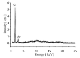
このように調整された条件で取得したシリコンウエハの蛍光X線スペクトルを図6に示す。縦軸は蛍光X線強度を1秒当りの平均値(カウント/秒)として表わしたものである。この蛍光X線スペクトルは、試料の傾きが図5に示された傾斜モータ13bの読み値で1.0度に設定し、X線源3のMoターゲットを50KeV、0.5mAで動作させたときのものである。Siの明瞭な蛍光X線が検出されている。Arの蛍光X線も検出されているが、このArはシリコンウエハ近傍又はX線光路中の大気中のArが励起されたものと考えられる。
FIG. 6 shows a fluorescent X-ray spectrum of the silicon wafer obtained under the conditions adjusted as described above. The vertical axis represents the fluorescent X-ray intensity as an average value (count / second) per second. This fluorescent X-ray spectrum is obtained when the inclination of the sample is set to 1.0 degree as the reading value of the
図7は他の実施例を表わす。試料からの蛍光X線を受ける検出器側にもポリキャピラリーX線レンズ27が取り付けられている。そのポリキャピラリーX線レンズ27以外の構成は図1の実施例と同じである。
FIG. 7 shows another embodiment. A
このように、検出器側にもポリキャピラリーX線レンズ27を取り付けることにより、微粒子のような微小部からの信号を効率よく検出できるようになり、検出効率のみならず、微小部試料以外からのX線の信号を取り込まなくなるので、S/B(信号対バックグラウンド)比の向上にも役立つ。
Thus, by attaching the
図8と図9は1次X線照射側のポリキャピラリーX線レンズの他の実施例を表したものである。図8(A)は平面図、(B)は側面図であり、図9はモノキャピラリーの配列を概略的に示したポリキャピラリーX線レンズの斜視図である。 8 and 9 show another embodiment of the polycapillary X-ray lens on the primary X-ray irradiation side. 8A is a plan view, FIG. 8B is a side view, and FIG. 9 is a perspective view of a polycapillary X-ray lens schematically showing an arrangement of monocapillaries.
ポリキャピラリーX線レンズ35は図9に示されるように多数のモノキャピラリー5cを束ねた構造である。図8では個々のモノキャピラリーの図示は省略している。モノキャピラリー5cは図2,3に示したポリキャピラリーX線レンズ5を構成しているものと同じであるが、その束ね方が異なっている。
The
ポリキャピラリーX線レンズ35はX線に対面する入射面5aは円形である。入射面5aは点光源であるX線源から立体的なX線の放射を受ける。入射面35aに端面が配置された各モノキャピラリー35cに入射したX線を各モノキャピラリー35cで全反射させつつ出射面35bへ伝播させるため、各モノキャピラリー35cの内径は入射側のA部からB部にかけて拡大している。さらに中間部のB−C間で面配列から直線配列に並べ直しされている。さらに、出射側のC−D間で出射方向が一点に集中するように焦点を定めて配列されている。その焦点となる位置に試料を配置する。また、C−D間ではモノキュピラリーの内径は漸次縮小している。
In the
このような構造で、X線源に対面するポリキャピラリーX線レンズの入射面35aでは複数のモノキャピラリー35cの端部が面状に配列されているので、X線源から立体的に放射されるX線ほぼ全量がポリキャピラリーX線レンズ35に取り込まれる。ポリキャピラリーX線レンズ35内に取り込まれたX線は各モノキャピラリー35cの内壁で全反射を繰り返しながら、入射面から出射面にかけて内径がいったん広がった後、漸次細くなるモノキャピラリー35c内を進行し、試料に対面するポリキャピラリーX線レンズの出射面35bに至る。出射面35bでは複数のモノキャピラリー端部が試料に対して同一の全反射角度になるように試料表面に平行な線状に配列されている。また、水平方向では各モノキャピラリー35cの放射方向が試料の配置される位置に集中して向かうように配列されている。
With such a structure, since the end portions of the plurality of
図10は1次X線照射側のポリキャピラリーX線レンズのさらに他の実施例を表したものであり、モノキャピラリーの配列を概略的に示したポリキャピラリーX線レンズの斜視図である。図10に示すように全反射条件が著しく変わらない範囲で、出射面35bのモノキャピラリーを垂直方向に2段又は複数段とすれば、ポリキャピラリーX線レンズ35が小型化できる利点がある。
FIG. 10 shows still another embodiment of the polycapillary X-ray lens on the primary X-ray irradiation side, and is a perspective view of the polycapillary X-ray lens schematically showing the arrangement of monocapillaries. As shown in FIG. 10, the
図11は1次X線照射側のポリキャピラリーX線レンズのさらに他の実施例を表した斜視図である。図11に示すように、入射面35aを球面状にしてX線源からの放射X線を受光しやすくしている。また、出射面35bを上から見て曲線状に配列して出射X線の集光度を高めている。このようなポリキャピラリーX線レンズは小型化を図る上で好都合である。
FIG. 11 is a perspective view showing still another embodiment of the polycapillary X-ray lens on the primary X-ray irradiation side. As shown in FIG. 11, the
ポリキャピラリーX線レンズは最大径(B部)のモノキャピラリー原料を束ねたものを加熱して引き伸ばすことにより製作される。A部方向には引っ張って径を縮小させ、C−D方向には配列を平面的に抑えつつ引き伸ばしてモノキャピラリーが扇状に収束する配列となるようにする。 A polycapillary X-ray lens is manufactured by heating and stretching a bundle of monocapillary raw materials having the maximum diameter (part B). The diameter is reduced by pulling in the direction A, and the monocapillaries are converged in a fan shape by stretching in the CD direction while suppressing the arrangement in a plane.
実施例の測定データとしては、シリコンウエハ自体のものを示したが、シリコンウエハ上のFe2O3などの単一微粒子についても同様に測定することができる。 As the measurement data of the example, the data of the silicon wafer itself was shown, but single fine particles such as Fe 2 O 3 on the silicon wafer can be similarly measured.
本発明は、試料表面の微小領域又は試料表面についた微小物を全反射蛍光X線分析方法により元素分析するのに利用することができる。 The present invention can be used for elemental analysis of a minute region on a sample surface or a minute object attached to the sample surface by a total reflection X-ray fluorescence analysis method.
1 試料表面
2 1次X線照射部
3 X線源
5,27,35 ポリキャピラリーX線レンズ
7 スリット
9 照射位置
11 検出器
13 試料台
13a X−Y−Zステッピングモータ
13b 傾斜モータ
35a 入射面
35b 出射面
35c モノキャピラリー
DESCRIPTION OF
Claims (4)
1次X線を発生するX線源及びその1次X線を集光して前記試料台上に載置された試料に照射するポリキャピラリーX線レンズを含み、その1次X線を試料の表面に対し全反射を起こす入射角で入射させる1次X線照射部と、
前記試料台上に載置された試料の表面に対向して配置され、試料から発生する蛍光X線を検出する検出器と、を備えた全反射蛍光X線分析装置において、
前記ポリキャピラリーX線レンズはモノキャピラリーを多数束ねたものであり、各モノキャピラリーはその内径が受光部側の基端から放射側の先端にかけていったん拡大し、先端に向かって漸次細くなる形状をもったものであり、
前記ポリキャピラリーX線レンズは、X線光源に対面する入射面では前記モノキャピラリーの端部が円形面状に配列され、試料に対面する出射面では前記モノキャピラリーの端部が線状に、かつ該端部からの放射方向が一点に向かって集光するように配列されていることを特徴とする全反射蛍光X線分析装置。 A sample stage on which the sample is placed;
An X-ray source that generates primary X-rays and a polycapillary X-ray lens that collects the primary X-rays and irradiates the sample placed on the sample stage. A primary X-ray irradiator that is incident at an incident angle causing total reflection on the surface;
In the total reflection X-ray fluorescence analyzer, which is disposed opposite to the surface of the sample placed on the sample stage and includes a detector that detects fluorescent X-rays generated from the sample,
The polycapillary X-ray lens is a bundle of a large number of monocapillaries, and each monocapillary has a shape in which the inner diameter once expands from the proximal end on the light receiving unit side to the distal end on the radiation side, and gradually decreases toward the distal end. And
The polycapillary X-ray lens, the incident surface facing the X-ray light source end of the mono-capillary are arranged in a circular plane shape, the end linear the mono capillary at the exit surface facing the sample, and A total reflection X-ray fluorescence analyzer, wherein the arrangement is such that the radiation direction from the end portion is condensed toward one point .
Priority Applications (1)
| Application Number | Priority Date | Filing Date | Title |
|---|---|---|---|
| JP2006231713A JP5159068B2 (en) | 2005-09-01 | 2006-08-29 | Total reflection X-ray fluorescence analyzer |
Applications Claiming Priority (3)
| Application Number | Priority Date | Filing Date | Title |
|---|---|---|---|
| JP2005254037 | 2005-09-01 | ||
| JP2005254037 | 2005-09-01 | ||
| JP2006231713A JP5159068B2 (en) | 2005-09-01 | 2006-08-29 | Total reflection X-ray fluorescence analyzer |
Publications (3)
| Publication Number | Publication Date |
|---|---|
| JP2007093593A JP2007093593A (en) | 2007-04-12 |
| JP2007093593A5 JP2007093593A5 (en) | 2009-08-20 |
| JP5159068B2 true JP5159068B2 (en) | 2013-03-06 |
Family
ID=37979468
Family Applications (1)
| Application Number | Title | Priority Date | Filing Date |
|---|---|---|---|
| JP2006231713A Expired - Fee Related JP5159068B2 (en) | 2005-09-01 | 2006-08-29 | Total reflection X-ray fluorescence analyzer |
Country Status (1)
| Country | Link |
|---|---|
| JP (1) | JP5159068B2 (en) |
Families Citing this family (10)
| Publication number | Priority date | Publication date | Assignee | Title |
|---|---|---|---|---|
| JP5646147B2 (en) * | 2008-03-28 | 2014-12-24 | 公立大学法人大阪市立大学 | Method and apparatus for measuring a two-dimensional distribution |
| JP2010019584A (en) * | 2008-07-08 | 2010-01-28 | Central Japan Railway Co | Fluorescent x-ray analyzer |
| WO2010026750A1 (en) * | 2008-09-02 | 2010-03-11 | 国立大学法人京都大学 | Total-reflection fluorescent x-ray analysis device, and total-reflection fluorescent x-ray analysis method |
| JP2010197229A (en) * | 2009-02-25 | 2010-09-09 | Osaka City Univ | Fluorescent x-ray analyzer |
| JP5407075B2 (en) * | 2009-04-23 | 2014-02-05 | 公立大学法人兵庫県立大学 | X-ray analyzer |
| JP5964705B2 (en) * | 2012-09-14 | 2016-08-03 | 浜松ホトニクス株式会社 | Polycapillary lens |
| EP2762862B1 (en) * | 2013-01-30 | 2017-03-08 | Bruker AXS GmbH | XRF measurement apparatus for detecting contaminations on the bevel of a wafer |
| JP6501230B2 (en) | 2016-03-08 | 2019-04-17 | 株式会社リガク | Multi-element simultaneous fluorescent X-ray analyzer and multi-element simultaneous fluorescent X-ray analysis method |
| CN112105919B (en) * | 2018-06-08 | 2023-08-22 | 株式会社岛津制作所 | Fluorescent X-ray analysis device and fluorescent X-ray analysis method |
| CN115389538B (en) * | 2022-08-09 | 2023-12-29 | 深圳市埃芯半导体科技有限公司 | X-ray analysis device and method |
Family Cites Families (7)
| Publication number | Priority date | Publication date | Assignee | Title |
|---|---|---|---|---|
| JPH0740080B2 (en) * | 1986-06-19 | 1995-05-01 | 株式会社島津製作所 | X-ray beam focusing device |
| JP2675737B2 (en) * | 1993-05-06 | 1997-11-12 | 理学電機工業株式会社 | Total reflection X-ray fluorescence analysis method and analyzer |
| JPH0961382A (en) * | 1995-08-24 | 1997-03-07 | Hitachi Ltd | Total reflection fluorescent x-ray analyzer |
| JPH10227749A (en) * | 1997-02-14 | 1998-08-25 | Matsushita Electric Ind Co Ltd | Radiographic inspection device and method |
| CA2489646C (en) * | 2001-06-19 | 2010-02-09 | X-Ray Optical Systems, Inc. | Wavelength dispersive xrf system using focusing optic for excitation and a focusing monochromator for collection |
| JP2003202306A (en) * | 2002-01-08 | 2003-07-18 | Japan Science & Technology Corp | Total reflection fluorescent x-ray analysis method and apparatus having configuration using sample substrate and reflector for achieving multiple total reflection and convergence of x rays |
| JP4421327B2 (en) * | 2004-02-25 | 2010-02-24 | 浜松ホトニクス株式会社 | X-ray collimator and X-ray imaging apparatus |
-
2006
- 2006-08-29 JP JP2006231713A patent/JP5159068B2/en not_active Expired - Fee Related
Also Published As
| Publication number | Publication date |
|---|---|
| JP2007093593A (en) | 2007-04-12 |
Similar Documents
| Publication | Publication Date | Title |
|---|---|---|
| JP5159068B2 (en) | Total reflection X-ray fluorescence analyzer | |
| JP6937380B2 (en) | Methods for performing X-ray spectroscopy and X-ray absorption spectroscopy systems | |
| JP2008203245A (en) | X-ray analysis apparatus and x-ray analysis method | |
| JP2005106815A (en) | Optical alignment of x-ray microanalyzer | |
| JP3284198B2 (en) | X-ray fluorescence analyzer | |
| JP6851107B2 (en) | X-ray analyzer | |
| JP2004184314A (en) | X-ray fluorescence analytical device | |
| US6577705B1 (en) | Combinatorial material analysis using X-ray capillary optics | |
| EP3570311B1 (en) | Cathodoluminescence optical hub | |
| US20100226477A1 (en) | X-ray convergence element and x-ray irradiation device | |
| JP3718818B2 (en) | Cathodoluminescence sample holder and cathodoluminescence spectrometer | |
| US8421007B2 (en) | X-ray detection system | |
| Gao et al. | 3.3 Polycapillary X-ray Optics | |
| JP5062598B2 (en) | Mossbauer spectrometer | |
| JP2002189004A (en) | X-ray analyzer | |
| JP2008039772A (en) | X-ray analyzer and x-ray analysis method | |
| WO2007026750A1 (en) | Microchip and analyzing method and device employing it | |
| JP4694296B2 (en) | X-ray fluorescence three-dimensional analyzer | |
| WO2006095467A1 (en) | X-ray diffraction analyzing method and analyzer | |
| JP2004294168A (en) | X-ray spectroscope for micro-portion analysis | |
| Kleimenov et al. | High-resolution hard-X-ray fluorescence spectrometer | |
| JP3755034B2 (en) | Total reflection X-ray fluorescence analysis method and apparatus | |
| JPH08220027A (en) | X-ray fluorescence analyzer | |
| JP2010197229A (en) | Fluorescent x-ray analyzer | |
| JP5646147B2 (en) | Method and apparatus for measuring a two-dimensional distribution |
Legal Events
| Date | Code | Title | Description |
|---|---|---|---|
| A521 | Written amendment |
Free format text: JAPANESE INTERMEDIATE CODE: A523 Effective date: 20090702 |
|
| A621 | Written request for application examination |
Free format text: JAPANESE INTERMEDIATE CODE: A621 Effective date: 20090702 |
|
| A131 | Notification of reasons for refusal |
Free format text: JAPANESE INTERMEDIATE CODE: A131 Effective date: 20110802 |
|
| A977 | Report on retrieval |
Free format text: JAPANESE INTERMEDIATE CODE: A971007 Effective date: 20110804 |
|
| A521 | Written amendment |
Free format text: JAPANESE INTERMEDIATE CODE: A523 Effective date: 20110929 |
|
| A131 | Notification of reasons for refusal |
Free format text: JAPANESE INTERMEDIATE CODE: A131 Effective date: 20120508 |
|
| A521 | Written amendment |
Free format text: JAPANESE INTERMEDIATE CODE: A523 Effective date: 20120516 |
|
| TRDD | Decision of grant or rejection written | ||
| A01 | Written decision to grant a patent or to grant a registration (utility model) |
Free format text: JAPANESE INTERMEDIATE CODE: A01 Effective date: 20121211 |
|
| A61 | First payment of annual fees (during grant procedure) |
Free format text: JAPANESE INTERMEDIATE CODE: A61 Effective date: 20121211 |
|
| R150 | Certificate of patent or registration of utility model |
Free format text: JAPANESE INTERMEDIATE CODE: R150 |
|
| FPAY | Renewal fee payment (event date is renewal date of database) |
Free format text: PAYMENT UNTIL: 20151221 Year of fee payment: 3 |
|
| S533 | Written request for registration of change of name |
Free format text: JAPANESE INTERMEDIATE CODE: R313533 |
|
| R350 | Written notification of registration of transfer |
Free format text: JAPANESE INTERMEDIATE CODE: R350 |
|
| LAPS | Cancellation because of no payment of annual fees |