JP5155992B2 - Injection mold - Google Patents
Injection mold Download PDFInfo
- Publication number
- JP5155992B2 JP5155992B2 JP2009288111A JP2009288111A JP5155992B2 JP 5155992 B2 JP5155992 B2 JP 5155992B2 JP 2009288111 A JP2009288111 A JP 2009288111A JP 2009288111 A JP2009288111 A JP 2009288111A JP 5155992 B2 JP5155992 B2 JP 5155992B2
- Authority
- JP
- Japan
- Prior art keywords
- resin
- cavity
- gate
- bent portion
- mold
- Prior art date
- Legal status (The legal status is an assumption and is not a legal conclusion. Google has not performed a legal analysis and makes no representation as to the accuracy of the status listed.)
- Active
Links
- 238000002347 injection Methods 0.000 title description 28
- 239000007924 injection Substances 0.000 title description 28
- 239000011347 resin Substances 0.000 claims description 155
- 229920005989 resin Polymers 0.000 claims description 155
- 238000001746 injection moulding Methods 0.000 claims description 10
- 239000000047 product Substances 0.000 description 21
- 238000005452 bending Methods 0.000 description 7
- 230000007423 decrease Effects 0.000 description 7
- 238000004519 manufacturing process Methods 0.000 description 7
- 238000005034 decoration Methods 0.000 description 6
- 238000000034 method Methods 0.000 description 6
- 238000000465 moulding Methods 0.000 description 6
- 238000011144 upstream manufacturing Methods 0.000 description 5
- 238000007493 shaping process Methods 0.000 description 4
- 239000002184 metal Substances 0.000 description 3
- 230000000694 effects Effects 0.000 description 2
- 239000012467 final product Substances 0.000 description 2
- 230000001939 inductive effect Effects 0.000 description 2
- 230000002349 favourable effect Effects 0.000 description 1
Images


Landscapes
- Moulds For Moulding Plastics Or The Like (AREA)
- Injection Moulding Of Plastics Or The Like (AREA)
Description
本発明は、射出成形に用いる金型のゲート形状に関するものである。 The present invention relates to a gate shape of a mold used for injection molding.
樹脂射出成形においては、ゲートを用いてキャビティに溶融樹脂が注入される。ゲートは樹脂成形品の厚みや大きさに合わせて各種選択され、例えば、薄肉の樹脂成形品に対しては、図15に示すように、キャビティ3に連通する部分を幅広にしたファンゲート1を用いることがある(特許文献1参照)。
In resin injection molding, molten resin is injected into a cavity using a gate. Various gates are selected in accordance with the thickness and size of the resin molded product. For example, for a thin resin molded product, as shown in FIG. 15, a
図15及び図16に示すように、キャビティ3に連通する部分を幅広にしたファンゲート1を用いると、溶融樹脂をキャビティ3全体に均等に充填することができる。しかし、溶融樹脂がキャビティ3内に流入する際に、ファンゲート1の両側部に大きな圧力がかかり、溶融樹脂の流動速度が増すことがある。その結果、ファンゲート1を備えた射出成形用金型を用いて樹脂部の表面に加飾層が形成される樹脂成形品を製造すると、射出成形時に加飾層を形成するインキ層が流動速度の速い溶融樹脂によって流されてしまい、加飾層の不良な樹脂成形品が製造されることがあった。
As shown in FIGS. 15 and 16, when the
そこで、本発明は、溶融樹脂による加飾層のインキ流れを抑制し良好な樹脂成形品の製造が可能な射出成形用金型を得ることを目的としている。 Therefore, an object of the present invention is to obtain an injection mold that can suppress the ink flow of a decorative layer by a molten resin and can produce a good resin molded product.
本発明の射出成形用金型に係る第1特徴構成は、樹脂部の表面に加飾層を形成した樹脂成形品の製造に用いる射出成形用金型であって、
樹脂形成用のキャビティに樹脂を注入する扁平状の樹脂流通路を有するゲートを備え、
当該ゲートの両縁部のうち少なくともいずれか一方の縁部に、前記キャビティの側に前記樹脂流通路の幅がさらに広がるよう第1屈曲部を設けると共に、
当該第1屈曲部より下流に位置する前記ゲートの縁部を、当該縁部が接続する前記キャビティの内壁面に対して所定の角度をもった状態に接続して当該位置に第2屈曲部を構成し、
前記第1屈曲部と前記第2屈曲部との間に位置する縁部が、直線状の縁部を少なくとも一つ備えている点にある。
A first characteristic configuration relating to an injection mold of the present invention is an injection mold used for manufacturing a resin molded product in which a decorative layer is formed on the surface of a resin portion,
A gate having a flat resin flow path for injecting resin into a resin forming cavity,
A first bent portion is provided on at least one of the two edges of the gate so that the width of the resin flow passage further expands on the cavity side,
The edge of the gate located downstream from the first bent part is connected in a state having a predetermined angle with respect to the inner wall surface of the cavity to which the edge is connected, and the second bent part is placed at the position. Configure
The edge located between the first bent part and the second bent part is provided with at least one straight edge.
本構成によれば、樹脂流通路の幅が第1屈曲部から下流側で広くなっているため、まず、第1屈曲部の近傍において樹脂の流通速度が高まる。これはつまり、第1屈曲部よりも下流の空間が急激に広がるために、第1屈曲部の下手側では流通する樹脂の圧力が急激に低下することに起因する。第1屈曲部よりも上流を流れていた樹脂の流通方向は、上記圧力低下部が生じた結果、その方向に偏向される。このため、上記第1屈曲部近傍を流れる樹脂の量が相対的に多くなり、圧力が局所的に高まって流速が増大するのである。
従来のゲートでは、このようなゲート幅の偏向点が、ゲートとキャビティとの境界位置に唯一つ存在するものであった。よって、前述の如く加飾層のインキ流れ等の不都合が生じていた。
According to this configuration, since the width of the resin flow passage is widened on the downstream side from the first bent portion, first, the flow rate of the resin is increased in the vicinity of the first bent portion. In other words, since the space downstream from the first bent portion is suddenly expanded, the pressure of the resin flowing on the lower side of the first bent portion is rapidly reduced. The flow direction of the resin flowing upstream from the first bent portion is deflected in that direction as a result of the occurrence of the pressure drop portion. For this reason, the amount of resin flowing in the vicinity of the first bent portion is relatively increased, the pressure is locally increased, and the flow velocity is increased.
In the conventional gate, such a gate width deflection point exists only at the boundary position between the gate and the cavity. Therefore, as described above, inconveniences such as ink flow of the decorative layer have occurred.
しかしながら、本構成では、キャビティに対してゲートが最終的に開口する位置、即ち、第2屈曲部よりもさらに上流位置に第1屈曲部を設けている。これにより、特に、縁部近傍を流通する樹脂について、第1屈曲部を通過したのちの流通方向を一旦大きく偏向しておく。続いて樹脂が第2屈曲部近傍を通過する際にも、上記効果により樹脂の流速はある程度上昇する。しかし、既に第1屈曲部で樹脂流の方向がある程度偏向されているため、第2屈曲部における樹脂の偏向角度はそれ程大きなものではなくなる。よって、第2屈曲部の下流、即ち、キャビティの内部における樹脂圧の急激な低下が防止され、樹脂の高速流が生じ難くなる。
このように本構成の金型であれば、表面に加飾層を備えた樹脂成形品を製造する際に、溶融樹脂による加飾層のインキ流れを抑制して良好な樹脂成形品を製造できるようになった。
However, in this configuration, the first bent portion is provided at a position where the gate is finally opened with respect to the cavity, that is, at a position further upstream than the second bent portion. Thereby, in particular, with respect to the resin flowing in the vicinity of the edge, the flow direction after passing through the first bent portion is once largely deflected. Subsequently, even when the resin passes near the second bent portion, the flow rate of the resin increases to some extent due to the above effect. However, since the direction of the resin flow is already deflected to some extent at the first bent portion, the resin deflection angle at the second bent portion is not so large. Therefore, a rapid drop in the resin pressure downstream of the second bent portion, that is, inside the cavity is prevented, and a high-speed resin flow is less likely to occur.
Thus, if it is a metal mold | die of this structure, when manufacturing the resin molded product provided with the decoration layer on the surface, the ink flow of the decoration layer by molten resin can be suppressed and a favorable resin molded product can be manufactured. It became so.
本発明の射出成形用金型に係る第2特徴構成は、前記第1屈曲部から樹脂の流通方向下流側に連続する前記樹脂流通路に、前記キャビティの前記内壁面に対して平行な直線状の段部をなす第1直線部と、当該第1直線部の終点位置と前記第2屈曲部とを連接する第2直線部とを備えた点にある。 The second feature of the injection mold according to the present invention is that the resin flow passage continuing from the first bent portion to the downstream side in the resin flow direction is a straight line parallel to the inner wall surface of the cavity. And a second straight line portion connecting the end point position of the first straight line portion and the second bent portion.
本構成の如く、第1屈曲部に続く下流の樹脂流通路をキャビティの内壁面に平行に構成することで、第1屈曲部近傍を通過した後の樹脂の流れ方向をキャビティの内壁面と平行な方向に近付けることができる。このため、第2屈曲部近傍の上流を流れる樹脂の流れ方向と、下流を流れる樹脂の流れ方向との角度差が少なくなる。この結果、第2屈曲部近傍での樹脂圧の高まりをより低減して、加飾層のインキ流れを確実に防止することができる。 As in this configuration, the downstream resin flow passage following the first bent portion is configured in parallel to the inner wall surface of the cavity, so that the flow direction of the resin after passing near the first bent portion is parallel to the inner wall surface of the cavity. It can be approached in any direction. For this reason, the angle difference between the flow direction of the resin flowing upstream in the vicinity of the second bent portion and the flow direction of the resin flowing downstream is reduced. As a result, the increase in the resin pressure in the vicinity of the second bent portion can be further reduced, and the ink flow of the decorative layer can be reliably prevented.
本発明の射出成形用金型に係る第3特徴構成は、前記キャビティに対する前記ゲートの開口部のうち、当該開口部の長手方向の幅aと、前記第1直線部の長さbとが、0.1≦b/a≦0.2となるように構成した点にある。 The third feature of the injection mold according to the present invention is that, among the openings of the gate with respect to the cavity, the width a in the longitudinal direction of the opening and the length b of the first straight portion are: The configuration is such that 0.1 ≦ b / a ≦ 0.2.
本構成のごとく、キャビティに連通するゲートの開口部の幅aと、樹脂流通路に設けた第1直線部の長さbとの関係を規定することで、樹脂の流通状態を最適に設定することができる。
即ち、上記幅aに対して長さbを過大に設定すると、第1屈曲部近傍を通過した樹脂が第2屈曲部にまで行き届かずにキャビティに到達してしまう。この場合には、ゲートの開口部の両端部が、樹脂注入の為に機能していないことになり、結果的に過大な開口部を設けたことになる。そうなると、樹脂の流動を均一に分散することができず、インキ流れ発生のリスクが大きくなる。
また、長さbが過大であるということは、幅aが狭すぎると解釈することもできる。この場合には、樹脂の充填効率が悪化して樹脂成形品を効率的に製造することができなくなる。
一方、長さbを過小に設定すると、第1屈曲部より下流域において樹脂圧が低下する領域を十分に確保することができず、第1屈曲部近傍での樹脂流の偏向程度が減少する。この結果、樹脂がキャビティに進入した時点で流速が過大となるため好ましくない。
そこで、上記構成の如くb/aを0.1≦b/a≦0.2に設定することで、樹脂流速が過大になるのを防止し、かつ、製造工数を簡略化できる金型を得ることができた。
As in this configuration, the flow state of the resin is optimally set by defining the relationship between the width a of the opening of the gate communicating with the cavity and the length b of the first straight portion provided in the resin flow passage. be able to.
That is, if the length b is set excessively with respect to the width a, the resin that has passed through the vicinity of the first bent portion reaches the cavity without reaching the second bent portion. In this case, both ends of the opening of the gate do not function for resin injection, and as a result, an excessive opening is provided. If so, the flow of the resin cannot be uniformly dispersed, and the risk of ink flow increases.
Further, the fact that the length b is excessive can be interpreted as the width a being too narrow. In this case, the resin filling efficiency is deteriorated and the resin molded product cannot be efficiently manufactured.
On the other hand, if the length b is set too small, it is not possible to secure a sufficient area where the resin pressure decreases in the downstream area from the first bent portion, and the degree of deflection of the resin flow near the first bent portion is reduced. . As a result, the flow rate becomes excessive when the resin enters the cavity, which is not preferable.
Therefore, by setting b / a to 0.1 ≦ b / a ≦ 0.2 as in the above configuration, a mold that prevents the resin flow rate from becoming excessive and simplifies the manufacturing process can be obtained. I was able to.
本発明の射出成形用金型に係る第4特徴構成は、前記第1直線部の長さbと、前記第1直線部の終点位置から前記内壁面に対して垂直な方向の長さL1とが、0.6≦L1/b≦1.2 となるように構成した点にある。 The fourth characteristic configuration relating to the injection molding die of the present invention includes a length b of the first straight portion, and a length L1 in a direction perpendicular to the inner wall surface from the end point position of the first straight portion. However, it is the point comprised so that it might become 0.6 <= L1 / b <= 1.2.
この構成のように、第1直線部の長さbと、所謂、第1直線部からキャビティまでの長さL1とを規定することによっても樹脂の流通状態を制御することができる。
即ち、長さbに対して長さL1が過小であると、第1屈曲部近傍で増大した樹脂の流速が維持されたまま樹脂がキャビティ内に到達してしまい、インキ流れを誘発する。
一方、長さbに対して長さL1が過大になると、第1屈曲部近傍で一旦減速した溶融樹脂の流速が再度大きくなり、第2屈曲部の近傍で樹脂の流速が再度高まってしまう。
このため本構成の如く、0.6≦L1/b≦1.2 と設定することで、インキ流れのない健全な樹脂成形品を形成可能な金型を得ることができた。
As in this configuration, the flow state of the resin can also be controlled by defining the length b of the first straight portion and the so-called length L1 from the first straight portion to the cavity.
That is, if the length L1 is too small with respect to the length b, the resin reaches the cavity while maintaining the increased flow velocity of the resin in the vicinity of the first bent portion, thereby inducing the ink flow.
On the other hand, when the length L1 is excessive with respect to the length b, the flow rate of the molten resin once decelerated near the first bent portion increases again, and the flow velocity of the resin increases again near the second bent portion.
Therefore, as in this configuration, by setting 0.6 ≦ L1 / b ≦ 1.2, a mold capable of forming a sound resin molded product without ink flow could be obtained.
本発明の射出成形用金型に係る第5特徴構成は、前記第2屈曲部から前記内壁面に対して垂直な方向であって前記キャビティとは反対側に設定した基準線と、前記第2直線部とのなす角度θを、20°≦θ≦40°となるように構成した点にある。 According to a fifth feature of the injection mold of the present invention, a reference line set in a direction perpendicular to the inner wall surface from the second bent portion and opposite to the cavity, and the second The angle θ formed with the straight line portion is that 20 ° ≦ θ ≦ 40 °.
本構成に係る角度θは、キャビティに注入する樹脂の流れ方向を最終的に決定するものである。
つまり、当該角度θが過大であるということは、ゲートの平均的な幅に対して開口部の幅が大きいということになる。この場合、上記第3特徴構成について説明したのと同様に、樹脂の注入効率が低下してしまう。
また、角度θが過大になれば、第1屈曲部近傍を通過した樹脂が第2屈曲部の位置まで流通せずにキャビティに進入する割合が多くなる。つまり、余分な長さを有する開口部を形成したことになり、前述の如く、樹脂の流動を均一に分散することができず、インキ流れ発生のリスクが大きくなる。
一方、角度θが過小であれば、第2直線部に沿って流通する樹脂の流れ方向と、キャビティに進入して偏向した後の樹脂の流れ方向との角度変化が大きくなる。樹脂の圧力は第1屈曲部を通過したのちある程度低下している。よって、第2屈曲部の下流のキャビティにおいて樹脂圧の低下が大きくなり、樹脂成形品の表面に樹脂の収縮差による歪みやヒケが発生するおそれが生じてしまう。
しかし、本構成の如く、20°≦θ≦40°に設定することで、インキ流れやヒケの発生を有効に防止する金型を得ることができる。
The angle θ according to the present configuration finally determines the flow direction of the resin injected into the cavity.
That is, when the angle θ is excessive, the width of the opening is larger than the average width of the gate. In this case, the resin injection efficiency decreases as described for the third characteristic configuration.
If the angle θ is excessive, the ratio of the resin that has passed through the vicinity of the first bent portion enters the cavity without flowing to the position of the second bent portion. That is, an opening having an extra length is formed, and as described above, the flow of the resin cannot be uniformly dispersed, and the risk of ink flow increases.
On the other hand, if the angle θ is too small, the change in the angle between the flow direction of the resin flowing along the second linear portion and the flow direction of the resin after having entered the cavity and deflected becomes large. The pressure of the resin decreases to some extent after passing through the first bent portion. Accordingly, the resin pressure is greatly reduced in the cavity downstream of the second bent portion, and there is a possibility that distortion or sink marks due to the difference in shrinkage of the resin occur on the surface of the resin molded product.
However, as in this configuration, by setting 20 ° ≦ θ ≦ 40 °, it is possible to obtain a mold that effectively prevents the occurrence of ink flow and sink marks.
以下、本発明の実施形態を図面に基づいて説明する。
〔第1実施形態〕
図1〜図3は、樹脂部の表面に加飾層を形成した樹脂成形品Pを製造するために用いる射出成形用金型に備えられたゲート1及び射出成形用金型により形成されるキャビティ3の形状を示すものである。図1は金型内におけるゲート1及びキャビティ3の形状を示す正面図であり、図2は図1のII−II矢視断面図であり、図3は、図1の斜視図である
。なお、本実施形態のゲート1はキャビティ3の側方から樹脂を注入するサイドゲートである。
Hereinafter, embodiments of the present invention will be described with reference to the drawings.
[First Embodiment]
1 to 3 show a cavity formed by a
図1に示すように、樹脂形成用のキャビティ3に樹脂を注入するゲート1は扁平状の樹脂流通路を有し、ゲート1の幅狭な部分はスプルー2に連通し、幅広な部分がキャビティ3に連通する。射出成形装置から射出された溶融樹脂はスプルー2を介してゲート1内に流入し、ゲート1を通過してキャビティ3内に注入された後、型内で冷却・固化することによって、キャビティ3に対応した形状の樹脂成形品Pが得られる。
As shown in FIG. 1, a
ゲート1は、その縁部1Aがスプルー2に連通する開口部の端部1aからキャビティ3に連通する開口部1Bに向けて樹脂流通路の幅が徐々に広がるよう形成されている。
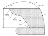
図4に示すように、ゲート1の縁部1Aに、キャビティ3の側に樹脂流通路の幅がさらに広がるよう第1屈曲部1bを設け、第1屈曲部1bより下流に位置するゲート1の縁部1Aを、縁部1Aが接続するキャビティ3の内壁面3Aに対して所定の角度をもった状態で端部1dに接続し、この端部1dが第2屈曲部となる。
The
As shown in FIG. 4, the
第1屈曲部1bと第2屈曲部1dとの間に位置する縁部1Aには、直線状の縁部Sが少なくとも一つ備えられている。本実施形態では、縁部1Aの第1屈曲部1bから樹脂の流通方向下流側に連続する樹脂流通路に、直線状の縁部Sとして、キャビティ3の内壁面3Aに対して平行な直線状の段部をなす第1直線部S1と第1直線部S1の終点位置1cと第2屈曲部1dを連接する第2直線部S2とを備える。
At least one linear edge S is provided on the
このように、キャビティ3に対してゲート1が最終的に開口する第2屈曲部1dよりもさらに上流位置に第1屈曲部1bを設ける。これにより、特に、縁部1A近傍を流通する樹脂は、第1屈曲部1bを通過したのちの流通方向を一旦大きく偏向する。続いて樹脂が第2屈曲部1d近傍を通過する際にも、上記効果により樹脂の流速はある程度上昇する。しかし、既に第1屈曲部1bで樹脂流の方向がある程度偏向されているため、第2屈曲部1dにおける樹脂の偏向角度はそれ程大きなものではなくなる。よって、第2屈曲部1dの下流であるキャビティ3の内部における樹脂圧の急激な低下が防止され、樹脂の高速流が生じ難くなった。
In this way, the first
また、第1屈曲部1bに続く下流の樹脂流通路をキャビティ3の内壁面3Aに平行に構成することで、第1屈曲部1b近傍を通過した後の樹脂の流れ方向をキャビティ3の内壁面3Aと平行な方向に近付けることができる。このため、第2屈曲部1d近傍の上流を流れる樹脂の流れ方向と、下流を流れる樹脂の流れ方向との角度差が少なくなる。この結果、第2屈曲部1d近傍での樹脂圧の高まりをより低減して、加飾層のインキ流れを確実に防止することができた。
Further, by forming the downstream resin flow passage following the first
なお、この実施形態においては、図2に示されるように、ゲート1の厚みはキャビティ3に向かって徐々に薄くなっており、かつ、ゲート1はキャビティ3の下端部に連通されるように途中から湾曲している。このようにゲート1を湾曲させることで、加飾シートが金型の型面により折り曲げられてしまう不具合を防止している。また、ゲート1のスプルー2に近い領域には、先に冷えて固化しかかった樹脂を除くための溜まり部が形成されている。
In this embodiment, as shown in FIG. 2, the thickness of the
[ゲートの寸法比について]
図1及び図4に示す、キャビティ3に対するゲート1の開口部1Bのうち、当該開口部1Bの長手方向の幅aと、ゲート1の第1直線部S1の長さbとが、0.1≦b/a≦0.2となるように構成することが望ましい。キャビティ3に連通するゲート1の開口部1Bの幅aと、樹脂流通路に設けた第1直線部S1の長さbとの関係を規定することで、樹脂の流通状態を最適に設定することができる。
[About dimensional ratio of gate]
Of the
幅aに対して長さbを過大に設定すると、第1屈曲部1b近傍を通過した樹脂が第2屈曲部1dにまで行き届かずにキャビティ3に到達してしまう。この場合には、ゲート1の開口部1Bの両端部が、樹脂注入の為に機能していないことになり、結果的に過大な開口部1Bを設けたことになる。そうなると、樹脂の流動を均一に分散することができず、インキ流れ発生のリスクが大きくなる。また、長さbが過大であるということは、幅aが狭すぎると解釈することもできるため、樹脂の充填効率が悪化し樹脂成形品の製造効率が下がる。
一方、長さbを過小に設定すると、第1屈曲部1bより下流域において樹脂圧が低下する領域を十分に確保することができず、第1屈曲部1b近傍での樹脂流の偏向程度が減少する。この結果、樹脂がキャビティ3に進入した時点で流速が過大となり好ましくない。
If the length b is excessively set with respect to the width a, the resin that has passed through the vicinity of the first
On the other hand, if the length b is set too small, a region where the resin pressure decreases in the downstream region from the first
また、ゲート1の第1直線部S1の長さbと、第1直線部S1の終点位置1cからキャビティ3の内壁面3Aに対して垂直な方向の長さL1とが、0.6≦L1/b≦1.2となるように構成することが望ましい。第1直線部S1の長さbと、所謂、第1直線部S1からキャビティ3までの長さL1とを規定することによっても樹脂の流通状態を制御することができる。
The length b of the first straight line portion S1 of the
長さbに対して長さL1が過小であると、第1屈曲部1b近傍で増大した樹脂の流速が維持されたまま樹脂がキャビティ3内に到達してしまい、インキ流れを誘発する。
一方、長さbに対して長さL1が過大になると、第1屈曲部1b近傍で一旦減速した溶融樹脂の流速が再度大きくなり、第2屈曲部1dの近傍で樹脂の流速が再度高まってしまう。
If the length L1 is too small with respect to the length b, the resin reaches the
On the other hand, when the length L1 is excessive with respect to the length b, the flow rate of the molten resin once decelerated in the vicinity of the first
また、ゲート1の縁部1Aの第2屈曲部1dからキャビティ3の内壁面3Aに対して垂直な方向であってキャビティ3とは反対側に設定した基準線Aと、縁部1Aの第2直線部S2とのなす角度θを、20°≦θ≦40°となるように構成することが望ましい。角度θは、キャビティに注入する樹脂の流れ方向を最終的に決定するものである。
つまり、当該角度θが過大であるということは、ゲート1の平均的な幅に対して開口部1Bの幅が大きいということになり、樹脂の注入効率が低下してしまう。
Further, a reference line A set in a direction perpendicular to the
That is, when the angle θ is excessive, the width of the
また、角度θが過大になれば、第1屈曲部1b近傍を通過した樹脂が第2屈曲部1dの位置まで流通せずにキャビティ3に進入する割合が多くなる。つまり、余分な長さを有する開口部1Bを形成したことになり、前述の如く、樹脂の流動を均一に分散することができず、インキ流れ発生のリスクが大きくなる。
一方、角度θが過小であれば、第2直線部S2に沿って流通する樹脂の流れ方向と、キャビティ3に進入して偏向した後の樹脂の流れ方向との角度変化が大きくなる。樹脂の圧力は第1屈曲部1bを通過したのちある程度低下している。よって、第2屈曲部1dの下流のキャビティ3において樹脂圧の低下が大きくなり、樹脂成形品の表面に樹脂の収縮差による歪みやヒケが発生するおそれが生じてしまう。
If the angle θ is excessive, the proportion of the resin that has passed through the vicinity of the first
On the other hand, if the angle θ is too small, the change in the angle between the flow direction of the resin flowing along the second linear portion S2 and the flow direction of the resin after entering and deflecting into the
また、ゲート1のスプルー2に連通する開口部の端部1aからキャビティ3の内壁面3Aに対して垂直な方向の長さLに対して、第1直線部S1の終点位置1cからキャビティ3の内壁面3Aに対して垂直な方向の長さL1は、第1屈曲部1bより下流の樹脂流通路を確保する上で、0.2≦L1/L≦0.5であることが望ましい。
Further, the length L of the
[樹脂成形の処理手順]
図5に示すように、第1型11にゲート1、スプルー2、ノズル13が設けられており、第2型12に加飾シートとして転写シート14を保持するクランプ15が設けられている。転写シート14は加飾層(転写層)14aと基体シート14bとで構成されており、加飾層(転写層)14aが樹脂部4の表面を加飾する。第2型12のキャビティ面に転写シート14を配置した後、第1型11と第2型12とを型締めし、第1型11と第2型12に配置された転写シート14との間にキャビティ3が形成する。キャビティ3に第1型11に備えられたノズル13からスプルー2及びゲート1を経由して溶融樹脂が注入される。
[Resin molding process]
As shown in FIG. 5, the
樹脂が硬化した後、図6に示すように、型締めを開放し、第1型11に設けられたエジェクタピン(図示せず)により樹脂成形品Pを取り出す。その後、ゲート1及びスプルー2の部分の不要な樹脂部4bをカットして樹脂部4aの表面に加飾層14aが形成された最終製品を得る。
After the resin is cured, as shown in FIG. 6, the mold clamping is released, and the resin molded product P is taken out by an ejector pin (not shown) provided in the
〔第2実施形態〕
第1実施形態では、ゲート1の縁部1Aの第1直線部S1を段部として形成した構成を示したが、必ずしも第1直線部S1を段部として形成する必要はなく、図7に示すように、第1屈曲部1bと第2屈曲部1dとの間に位置する縁部1Aに外方に向けて斜めに傾斜した第1直線部S1を備えるようにしてもよい。
[Second Embodiment]
In the first embodiment, the configuration in which the first straight portion S1 of the
〔第3実施形態〕
図8〜図10は、樹脂部の表面に加飾層を形成した樹脂成形品Pを製造するために用いる射出成形用金型に備えられたゲート1及び射出成形用金型により形成されるキャビティ3の形状を示すものである。図8は金型内におけるゲート1及びキャビティ3の形状を示す平面図であり、図9は図8のIX−IX矢視断面図であり、図10は、図8の斜視図で
ある。なお、本実施形態のゲート1はキャビティ3に対して直接、溶融樹脂を注入するリブ状のダイレクトゲートである。
[Third Embodiment]
FIGS. 8 to 10 show a cavity formed by the
図8に示すように、樹脂形成用のキャビティ3に樹脂を注入するゲート1は扁平状の樹脂流通路を有し、ゲート1の幅狭な部分はスプルー2に連通し、幅広な部分がキャビティ3に連通する。射出成形装置から射出された溶融樹脂はスプルー2を介してゲート1内に流入し、ゲート1を通過してキャビティ3内に注入された後、型内で冷却・固化することによって、キャビティ3に対応した形状の樹脂成形品Pが得られる。
As shown in FIG. 8, the
ゲート1は、その縁部1Aがスプルー2に連通する開口部の端部1aからキャビティ3に連通する開口部1Bに向けて樹脂流通路の幅が徐々に広がるよう形成されている。
図11に示すように、ゲート1の縁部1Aに、キャビティ3の側に樹脂流通路の幅がさらに広がるよう第1屈曲部1bを設け、第1屈曲部1bより下流に位置するゲート1の縁部1Aを、縁部1Aが接続するキャビティ3の内壁面3Aに対して所定の角度をもった状態で端部1dに接続し、この端部1dが第2屈曲部となる。
The
As shown in FIG. 11, the
第1屈曲部1bと第2屈曲部1dとの間に位置する縁部1Aには、直線状の縁部Sが少なくとも一つ備えられている。本実施形態では、縁部1Aの第1屈曲部1bから樹脂の流通方向下流側に連続する樹脂流通路に、直線状の縁部Sとして、キャビティ3の内壁面3Aに対して平行な直線状の段部をなす第1直線部S1と第1直線部S1の終点位置1cと第2屈曲部1dを連接する第2直線部S2とを備える。
At least one linear edge S is provided on the
なお、この実施形態においては、図9に示されるように、ゲート1の厚みはキャビティ3に向かって徐々に薄くなっており、スプルー近くの厚みの大きい領域の一部は、先に冷えて固化しかかった樹脂を除くための溜まり部となる。
In this embodiment, as shown in FIG. 9, the thickness of the
[ゲートの寸法比について]
ゲート1がリブ状のダイレクトゲートである第3実施形態においても、第1実施形態と同様に、図8及び図11に示す、キャビティ3に対するゲート1の開口部1Bのうち、当該開口部1Bの長手方向の幅aと、ゲート1の第1直線部S1の長さbとが、0.1≦b/a≦0.2となるように構成することが望ましい。
[About dimensional ratio of gate]
In the third embodiment in which the
また、ゲート1の第1直線部S1の長さbと、第1直線部S1の終点位置1cからキャビティ3の内壁面3Aに対して垂直な方向の長さL1とが、0.6≦L1/b≦1.2となるように構成することが望ましい。
The length b of the first straight line portion S1 of the
また、ゲート1の縁部1Aの第2屈曲部1dからキャビティ3の内壁面3Aに対して垂直な方向であってキャビティ3とは反対側に設定した基準線Aと、縁部1Aの第2直線部S2とのなす角度θを、20°≦θ≦40°となるように構成することが望ましい。
Further, a reference line A set in a direction perpendicular to the
また、ゲート1のスプルー2に連通する開口部の端部1aからキャビティ3の内壁面3Aに対して垂直な方向の長さLに対して、第1直線部S1の終点位置1cからキャビティ3の内壁面3Aに対して垂直な方向の長さL1は、第1屈曲部1bより下流の樹脂流通路を確保する上で、0.2≦L1/L≦0.5であることが望ましい。
Further, the length L of the
[樹脂成形の処理手順]
図12に示すように、第1型11にリブ状のダイレクトゲート1、スプルー2、ノズル13が設けられており、第2型12に加飾シートとして転写シート14を保持するクランプ15が設けられている。第2型12のキャビティ面に転写シート14を配置した後、第1型11と第2型12とを型締めすると、第1型11と第2型12に配置された転写シート14との間にキャビティ3が形成される。キャビティ3に第1型11に備えられたノズル13からリブ状のダイレクトゲート1を経由して溶融樹脂が注入される。
[Resin molding process]
As shown in FIG. 12, the
樹脂が硬化した後、図13に示すように、型締めを開放し、第1型11に設けられたエジェクタピンにより樹脂成形品Pを取り出す。その後、不要なゲート1及びスプルー2の部分の樹脂部4bをカットして樹脂部4aの表面に加飾層14aが形成された最終製品を得る。
After the resin is cured, as shown in FIG. 13, the mold clamping is released, and the resin molded product P is taken out by the ejector pin provided in the
〔第4実施形態〕
第3実施形態では、ゲート1の縁部1Aの第1直線部S1を段部として形成した構成を示したが、必ずしも第1直線部S1を段部として形成する必要はなく、図7に示すように、第1屈曲部1bと第2屈曲部1dとの間に位置する縁部1Aに外方に向けて斜めに傾斜した第1直線部S1を備えるようにしてもよい。
[Fourth Embodiment]
In the third embodiment, the configuration in which the first straight portion S1 of the
〔別実施形態〕
(1)上記実施形態では、ゲート1の両縁部1A,1Aについて、第1屈曲部1bと第2屈曲部1dとの間に直線状の縁部Sを備える構成を示したが、両縁部1A,1Aのうち、いずれか一方にのみに上記直線状の縁部Sを備えるようにしてもよい。
[Another embodiment]
(1) In the above-described embodiment, the configuration in which the
(2)上記実施形態では、加飾層を形成する加飾シートとして転写シートを用いたが、転写シートに代えて基体シートと加飾層とが一体となって樹脂部の表面を加飾するインサートシートを用いてもよい。 (2) In the said embodiment, although the transfer sheet was used as a decorating sheet which forms a decorating layer, it replaces with a transfer sheet and a base sheet and a decorating layer unite and decorate the surface of a resin part. An insert sheet may be used.
本発明に係る射出成形用金型は、樹脂の表面に加飾層が形成される樹脂成形品の製造において広く利用することができる。 The mold for injection molding according to the present invention can be widely used in the production of resin molded products in which a decorative layer is formed on the surface of the resin.
1 ゲート
1A 縁部
1b 第1屈曲部
1d 第2屈曲部
2 スプルー
3 キャビティ
11 第1型
12 第2型
14 転写シート(加飾シート)
P 樹脂成形品
S1 第1直線部
S2 第2直線部
DESCRIPTION OF
P resin molded product S1 first straight part S2 second straight part
Claims (1)
1つの面が前記キャビティ外に延びる前記加飾シートに沿うように形成され、前記キャビティに接続された、前記キャビティに溶融樹脂を射出する、扁平形状の樹脂流通路であるゲートと、
前記ゲート内の前記加飾シートに向かって、前記ゲートに溶融樹脂を流出するスプルーとを備え、
前記ゲートの縁部は、前記樹脂流通路の溶融樹脂流れ方向下流側の幅を広げる第1屈曲部と、前記キャビティに対する前記ゲートの開口部の長手方向の端部である第2屈曲部と、前記第1屈曲部から前記開口部の長手方向に延びる第1直線部と、前記第1直線部の終点位置と前記第2屈曲部とを接続する第2直線部とを含み、
前記開口部の長手方向の幅をa、前記第1直線部の長さをb、前記第2直線部の前記開口部の長手方向に直交する方向の長さをL1、前記直交する方向に前記キャビティの外側に設定された基準線と、前記第2直線部とのなす角度をθとすると、
0.1≦b/a≦0.2
0.6≦L1/b≦1.2
20℃≦θ≦40℃
である、射出成形用金型。 A cavity in which a decorative sheet is arranged on the cavity surface;
One surface is formed along the decorative sheet extending outside the cavity, connected to the cavity, and a gate that is a flat resin flow path for injecting molten resin into the cavity;
A sprue that flows out molten resin to the gate toward the decorative sheet in the gate,
Edge of the gate, a first bent portion to increase the width of the molten resin flow direction downstream side of the resin passage, and a second bent portion in the longitudinal direction of the end portion of the opening of the gate with respect to the cavity, A first straight portion extending from the first bent portion in the longitudinal direction of the opening, and a second straight portion connecting the end point position of the first straight portion and the second bent portion,
The width of the opening in the longitudinal direction is a, the length of the first straight portion is b, the length of the second straight portion in the direction perpendicular to the longitudinal direction of the opening is L1, and the length in the perpendicular direction is When the angle formed between the reference line set outside the cavity and the second straight line portion is θ,
0.1 ≦ b / a ≦ 0.2
0.6 ≦ L1 / b ≦ 1.2
20 ° C ≦ θ ≦ 40 ° C
The mold for injection molding.
Priority Applications (2)
| Application Number | Priority Date | Filing Date | Title |
|---|---|---|---|
| JP2009288111A JP5155992B2 (en) | 2009-12-18 | 2009-12-18 | Injection mold |
| CN201010610707.6A CN102166811B (en) | 2009-12-18 | 2010-12-16 | Mold for injection molding |
Applications Claiming Priority (1)
| Application Number | Priority Date | Filing Date | Title |
|---|---|---|---|
| JP2009288111A JP5155992B2 (en) | 2009-12-18 | 2009-12-18 | Injection mold |
Publications (2)
| Publication Number | Publication Date |
|---|---|
| JP2011126195A JP2011126195A (en) | 2011-06-30 |
| JP5155992B2 true JP5155992B2 (en) | 2013-03-06 |
Family
ID=44289315
Family Applications (1)
| Application Number | Title | Priority Date | Filing Date |
|---|---|---|---|
| JP2009288111A Active JP5155992B2 (en) | 2009-12-18 | 2009-12-18 | Injection mold |
Country Status (2)
| Country | Link |
|---|---|
| JP (1) | JP5155992B2 (en) |
| CN (1) | CN102166811B (en) |
Cited By (1)
| Publication number | Priority date | Publication date | Assignee | Title |
|---|---|---|---|---|
| WO2015152131A1 (en) * | 2014-04-04 | 2015-10-08 | 日本写真印刷株式会社 | Injection molding die and method for manufacturing resin molding |
Families Citing this family (5)
| Publication number | Priority date | Publication date | Assignee | Title |
|---|---|---|---|---|
| DE102013205141A1 (en) * | 2013-03-22 | 2014-09-25 | BSH Bosch und Siemens Hausgeräte GmbH | Melting control system for In-Mold-Decoration (IMD) or In-Mold-Labeling (IML) injection molding processes |
| CN106671359B (en) * | 2017-01-12 | 2019-09-27 | 青岛佳友模具科技有限公司 | A kind of stepped die device of multi-layer injection molding |
| CN114786910A (en) * | 2020-01-16 | 2022-07-22 | Nok株式会社 | Molding die and sealing member |
| JP2022030937A (en) * | 2020-08-07 | 2022-02-18 | 船井電機株式会社 | Manufacturing method for resin molded products and display devices |
| CN113650241A (en) * | 2021-07-27 | 2021-11-16 | 宁波均胜群英汽车系统股份有限公司 | Pouring gate for thin-wall injection molding |
Family Cites Families (6)
| Publication number | Priority date | Publication date | Assignee | Title |
|---|---|---|---|---|
| EP0546234A1 (en) * | 1991-12-12 | 1993-06-16 | Ab Cerbo | An arrangement in moulding tools intended for the injection moulding of a container while simultaneously affixing a label or the like thereto |
| CN1187150C (en) * | 2000-04-28 | 2005-02-02 | 株式会社东芝 | Metal mould device and method for manufacturing cast-part and box part |
| JP3427060B2 (en) * | 2000-04-28 | 2003-07-14 | 株式会社東芝 | Manufacturing method of housing parts |
| JP4110322B2 (en) * | 2003-01-15 | 2008-07-02 | ヤマウチ株式会社 | Weldless mold, cylindrical rubber elastic body manufactured thereby, and rubber roller manufactured using the same |
| JP2005215497A (en) * | 2004-01-30 | 2005-08-11 | Nippon Zeon Co Ltd | Light diffusion plate and its manufacturing method |
| JP2008100415A (en) * | 2006-10-18 | 2008-05-01 | Victor Kogyo Kk | Method for producing decorative resin molding |
-
2009
- 2009-12-18 JP JP2009288111A patent/JP5155992B2/en active Active
-
2010
- 2010-12-16 CN CN201010610707.6A patent/CN102166811B/en active Active
Cited By (5)
| Publication number | Priority date | Publication date | Assignee | Title |
|---|---|---|---|---|
| WO2015152131A1 (en) * | 2014-04-04 | 2015-10-08 | 日本写真印刷株式会社 | Injection molding die and method for manufacturing resin molding |
| JP5965092B2 (en) * | 2014-04-04 | 2016-08-03 | 日本写真印刷株式会社 | Injection mold and method for producing resin molded product |
| KR20160141701A (en) | 2014-04-04 | 2016-12-09 | 니혼샤신 인사츠 가부시키가이샤 | Injection molding die and method for manufacturing resin molding |
| TWI636862B (en) * | 2014-04-04 | 2018-10-01 | 日商日本寫真印刷股份有限公司 | Injection molding die and method of manufacturing resin molded article |
| KR102280117B1 (en) | 2014-04-04 | 2021-07-20 | 닛샤 가부시키가이샤 | Injection molding die and method for manufacturing resin molding |
Also Published As
| Publication number | Publication date |
|---|---|
| CN102166811A (en) | 2011-08-31 |
| CN102166811B (en) | 2014-12-03 |
| JP2011126195A (en) | 2011-06-30 |
Similar Documents
| Publication | Publication Date | Title |
|---|---|---|
| JP5155992B2 (en) | Injection mold | |
| JP4845180B2 (en) | Injection mold apparatus and injection molding method | |
| JP4209237B2 (en) | Resin molded product for vehicle and manufacturing apparatus thereof | |
| JP2000108167A (en) | Resin molded article having aperture holes and manufacture thereof | |
| JP4679203B2 (en) | Plastic ring-shaped injection mold | |
| CN101622118B (en) | Injection molding die | |
| KR20160141701A (en) | Injection molding die and method for manufacturing resin molding | |
| JP2008188855A (en) | Injection molding mold and injection molding method using the injection molding mold | |
| CN115366320A (en) | Injection product mold, injection product mold processing method and injection product | |
| CN101722631B (en) | Mold | |
| CN209738185U (en) | Injection mould | |
| CN211683229U (en) | Injection mold for automobile structural part | |
| JP5668395B2 (en) | Insert molding mold using surface sheet and method for producing molded article | |
| JP2002067099A (en) | Mold for injection-molded molding with thin wall and method for injection-molding molding with thin wall | |
| JP5817155B2 (en) | RTM molding method | |
| JP4867817B2 (en) | Injection insert molding | |
| JP6322018B2 (en) | Injection mold and method of manufacturing resin molded product using the same | |
| CN219141239U (en) | Appearance part, household appliance and mold | |
| JP2008023830A (en) | Resin molded article having skin and method for molding the same | |
| JP6880395B2 (en) | Manufacturing method of injection molded product | |
| CN207954520U (en) | Bumper plastic parts and automotive bumper mold | |
| CN211074523U (en) | Injection mold for base | |
| KR200194537Y1 (en) | Cutting type runner gate structure for injection molding | |
| JPWO2017169490A1 (en) | Injection mold, injection molding method, and molded product | |
| JP3411332B2 (en) | Injection mold |
Legal Events
| Date | Code | Title | Description |
|---|---|---|---|
| A977 | Report on retrieval |
Free format text: JAPANESE INTERMEDIATE CODE: A971007 Effective date: 20111021 |
|
| A131 | Notification of reasons for refusal |
Free format text: JAPANESE INTERMEDIATE CODE: A131 Effective date: 20111101 |
|
| A521 | Request for written amendment filed |
Free format text: JAPANESE INTERMEDIATE CODE: A523 Effective date: 20111217 |
|
| A131 | Notification of reasons for refusal |
Free format text: JAPANESE INTERMEDIATE CODE: A131 Effective date: 20121002 |
|
| A521 | Request for written amendment filed |
Free format text: JAPANESE INTERMEDIATE CODE: A523 Effective date: 20121108 |
|
| TRDD | Decision of grant or rejection written | ||
| A01 | Written decision to grant a patent or to grant a registration (utility model) |
Free format text: JAPANESE INTERMEDIATE CODE: A01 Effective date: 20121204 |
|
| A61 | First payment of annual fees (during grant procedure) |
Free format text: JAPANESE INTERMEDIATE CODE: A61 Effective date: 20121207 |
|
| FPAY | Renewal fee payment (event date is renewal date of database) |
Free format text: PAYMENT UNTIL: 20151214 Year of fee payment: 3 |
|
| R150 | Certificate of patent or registration of utility model |
Free format text: JAPANESE INTERMEDIATE CODE: R150 Ref document number: 5155992 Country of ref document: JP Free format text: JAPANESE INTERMEDIATE CODE: R150 |
|
| FPAY | Renewal fee payment (event date is renewal date of database) |
Free format text: PAYMENT UNTIL: 20151214 Year of fee payment: 3 |
|
| R250 | Receipt of annual fees |
Free format text: JAPANESE INTERMEDIATE CODE: R250 |
|
| R250 | Receipt of annual fees |
Free format text: JAPANESE INTERMEDIATE CODE: R250 |
|
| S533 | Written request for registration of change of name |
Free format text: JAPANESE INTERMEDIATE CODE: R313533 |
|
| R350 | Written notification of registration of transfer |
Free format text: JAPANESE INTERMEDIATE CODE: R350 |
|
| R250 | Receipt of annual fees |
Free format text: JAPANESE INTERMEDIATE CODE: R250 |
|
| R250 | Receipt of annual fees |
Free format text: JAPANESE INTERMEDIATE CODE: R250 |
|
| R250 | Receipt of annual fees |
Free format text: JAPANESE INTERMEDIATE CODE: R250 |
|
| R250 | Receipt of annual fees |
Free format text: JAPANESE INTERMEDIATE CODE: R250 |
|
| R250 | Receipt of annual fees |
Free format text: JAPANESE INTERMEDIATE CODE: R250 |
|
| R250 | Receipt of annual fees |
Free format text: JAPANESE INTERMEDIATE CODE: R250 |
|
| R250 | Receipt of annual fees |
Free format text: JAPANESE INTERMEDIATE CODE: R250 |