JP5154972B2 - Pneumatic tires for motorcycles - Google Patents
Pneumatic tires for motorcycles Download PDFInfo
- Publication number
- JP5154972B2 JP5154972B2 JP2008037616A JP2008037616A JP5154972B2 JP 5154972 B2 JP5154972 B2 JP 5154972B2 JP 2008037616 A JP2008037616 A JP 2008037616A JP 2008037616 A JP2008037616 A JP 2008037616A JP 5154972 B2 JP5154972 B2 JP 5154972B2
- Authority
- JP
- Japan
- Prior art keywords
- block
- tread
- block row
- constituting
- blocks
- Prior art date
- Legal status (The legal status is an assumption and is not a legal conclusion. Google has not performed a legal analysis and makes no representation as to the accuracy of the status listed.)
- Expired - Fee Related
Links
- 230000000694 effects Effects 0.000 description 19
- 230000007423 decrease Effects 0.000 description 7
- 239000004677 Nylon Substances 0.000 description 5
- 229920001778 nylon Polymers 0.000 description 5
- 238000011156 evaluation Methods 0.000 description 4
- 230000002093 peripheral effect Effects 0.000 description 2
- 229920000271 Kevlar® Polymers 0.000 description 1
- 241000135309 Processus Species 0.000 description 1
- 239000004760 aramid Substances 0.000 description 1
- 229920003235 aromatic polyamide Polymers 0.000 description 1
- 239000004761 kevlar Substances 0.000 description 1
- 230000003014 reinforcing effect Effects 0.000 description 1
Images
Classifications
-
- B—PERFORMING OPERATIONS; TRANSPORTING
- B60—VEHICLES IN GENERAL
- B60C—VEHICLE TYRES; TYRE INFLATION; TYRE CHANGING; CONNECTING VALVES TO INFLATABLE ELASTIC BODIES IN GENERAL; DEVICES OR ARRANGEMENTS RELATED TO TYRES
- B60C11/00—Tyre tread bands; Tread patterns; Anti-skid inserts
- B60C11/03—Tread patterns
- B60C11/11—Tread patterns in which the raised area of the pattern consists only of isolated elements, e.g. blocks
-
- B—PERFORMING OPERATIONS; TRANSPORTING
- B60—VEHICLES IN GENERAL
- B60C—VEHICLE TYRES; TYRE INFLATION; TYRE CHANGING; CONNECTING VALVES TO INFLATABLE ELASTIC BODIES IN GENERAL; DEVICES OR ARRANGEMENTS RELATED TO TYRES
- B60C11/00—Tyre tread bands; Tread patterns; Anti-skid inserts
- B60C11/03—Tread patterns
- B60C11/032—Patterns comprising isolated recesses
-
- B—PERFORMING OPERATIONS; TRANSPORTING
- B60—VEHICLES IN GENERAL
- B60C—VEHICLE TYRES; TYRE INFLATION; TYRE CHANGING; CONNECTING VALVES TO INFLATABLE ELASTIC BODIES IN GENERAL; DEVICES OR ARRANGEMENTS RELATED TO TYRES
- B60C11/00—Tyre tread bands; Tread patterns; Anti-skid inserts
- B60C11/03—Tread patterns
- B60C11/13—Tread patterns characterised by the groove cross-section, e.g. for buttressing or preventing stone-trapping
- B60C11/1376—Three dimensional block surfaces departing from the enveloping tread contour
- B60C11/1392—Three dimensional block surfaces departing from the enveloping tread contour with chamfered block edges
-
- B—PERFORMING OPERATIONS; TRANSPORTING
- B60—VEHICLES IN GENERAL
- B60C—VEHICLE TYRES; TYRE INFLATION; TYRE CHANGING; CONNECTING VALVES TO INFLATABLE ELASTIC BODIES IN GENERAL; DEVICES OR ARRANGEMENTS RELATED TO TYRES
- B60C2200/00—Tyres specially adapted for particular applications
- B60C2200/10—Tyres specially adapted for particular applications for motorcycles, scooters or the like
-
- B—PERFORMING OPERATIONS; TRANSPORTING
- B60—VEHICLES IN GENERAL
- B60C—VEHICLE TYRES; TYRE INFLATION; TYRE CHANGING; CONNECTING VALVES TO INFLATABLE ELASTIC BODIES IN GENERAL; DEVICES OR ARRANGEMENTS RELATED TO TYRES
- B60C2200/00—Tyres specially adapted for particular applications
- B60C2200/14—Tyres specially adapted for particular applications for off-road use
-
- Y—GENERAL TAGGING OF NEW TECHNOLOGICAL DEVELOPMENTS; GENERAL TAGGING OF CROSS-SECTIONAL TECHNOLOGIES SPANNING OVER SEVERAL SECTIONS OF THE IPC; TECHNICAL SUBJECTS COVERED BY FORMER USPC CROSS-REFERENCE ART COLLECTIONS [XRACs] AND DIGESTS
- Y10—TECHNICAL SUBJECTS COVERED BY FORMER USPC
- Y10S—TECHNICAL SUBJECTS COVERED BY FORMER USPC CROSS-REFERENCE ART COLLECTIONS [XRACs] AND DIGESTS
- Y10S152/00—Resilient tires and wheels
- Y10S152/03—Slits in threads
-
- Y—GENERAL TAGGING OF NEW TECHNOLOGICAL DEVELOPMENTS; GENERAL TAGGING OF CROSS-SECTIONAL TECHNOLOGIES SPANNING OVER SEVERAL SECTIONS OF THE IPC; TECHNICAL SUBJECTS COVERED BY FORMER USPC CROSS-REFERENCE ART COLLECTIONS [XRACs] AND DIGESTS
- Y10—TECHNICAL SUBJECTS COVERED BY FORMER USPC
- Y10S—TECHNICAL SUBJECTS COVERED BY FORMER USPC CROSS-REFERENCE ART COLLECTIONS [XRACs] AND DIGESTS
- Y10S152/00—Resilient tires and wheels
- Y10S152/902—Non-directional tread pattern having no circumferential rib and having blocks defined by circumferential grooves and transverse grooves
Landscapes
- Engineering & Computer Science (AREA)
- Mechanical Engineering (AREA)
- Tires In General (AREA)
Description
本発明は、二輪車に装着する二輪車用空気入りタイヤに関し、特に、泥濘地を含む不整地での走行を目的としたモトクロス、及びエンデューロ用の二輪車用空気入りタイヤに関する。 The present invention relates to a pneumatic tire for a motorcycle mounted on a motorcycle, and more particularly, to a motocross and a pneumatic tire for a motorcycle for an enduro for the purpose of traveling on rough terrain including a muddy ground.
不整地を走行する二輪車には、例えば、特許文献1に記載されているようなブロックパターンを有する二輪車用空気入りタイヤが使用されている(例えば、特許文献1参照。)。
不整地用ブロックパターンタイヤにおいては、トラクションを上げるために、路面を掘る効果を得る目的にブロック剛性を上げる事が必要となる。
従来では、ブロック自体を大きくしてブロック剛性を上げるか、使用するゴムの硬度を上げてブロック剛性を上げていた。
For a motorcycle traveling on rough terrain, for example, a pneumatic tire for a motorcycle having a block pattern as described in Patent Document 1 is used (see, for example, Patent Document 1).
In rough-patterned block pattern tires, in order to increase traction, it is necessary to increase block rigidity for the purpose of obtaining the effect of digging the road surface.
Conventionally, the block itself is enlarged to increase the block rigidity, or the hardness of the rubber used is increased to increase the block rigidity.
ブロック自体を大きくしてブロック剛性を上げた場合、ブロック踏面の動きも少なくなるために、硬質路面においてはブロック踏面でのグリップが確保できず(ブロック踏面が路面に馴染み難い)、結果的にブロックの接地面にスリットを入れたり、窪みを設けたりする対策(ブロック踏面の剛性の調整)を行いグリップや接地感を確保していた。即ち、ブロックの踏面にはある程度の柔軟性が必要となっている。 When the block itself is enlarged and the block rigidity is increased, the movement of the block tread also decreases, so the grip on the block tread cannot be secured on hard road surfaces (the block tread is difficult to adjust to the road surface), resulting in the block Measures (such as adjusting the rigidity of the tread of the block) were made by making slits in the grounding surface of the door or by providing a dent (to adjust the rigidity of the block tread). That is, a certain degree of flexibility is required for the tread surface of the block.
ブロック踏面でのグリップを向上させる事を目的に、ゴムの硬度を下げる事も一つの手段であるが、その場合、ゴムの柔らかさによる操縦安定性向上があっても、エッジの摩耗が早くなる問題がある。
また、ブロック自体を大きくした場合、タイヤのネガティブ率が減少するために、ブロック接地圧も減少し、泥濘地や軟質路面においては十分な初期の突刺し効果が得られない問題がある。
In order to improve the grip on the block tread, reducing the hardness of the rubber is one means, but in this case, even if the stability of the steering is improved by the softness of the rubber, the wear of the edge is accelerated. There's a problem.
Further, when the block itself is enlarged, the negative rate of the tire decreases, so that the block contact pressure also decreases, and there is a problem that a sufficient initial piercing effect cannot be obtained on muddy ground and soft road surfaces.
一方、ゴムの硬度を上げた場合、硬質路面では、ブロック自体を大きくした場合と同様に、十分なブロック踏面のグリップが得られなくなる。また、突刺し効果やエッジ効果が得られる泥濘地や軟質路面においても、そのゴムの硬さ故に滑りのコントロール性については効果が望めなかった。ネガティブ率が大きくてゴムの硬度が高い撓まないタイヤでは、路面に有効的に作用するブロック数も少なくなり、その結果、滑りのコントロール性が低下するのである。 On the other hand, when the hardness of the rubber is increased, on the hard road surface, as in the case where the block itself is enlarged, a sufficient grip on the block tread cannot be obtained. In addition, even in muddy areas and soft road surfaces where a piercing effect and an edge effect can be obtained, the effect of slip control was not expected due to the hardness of the rubber. In a tire that has a large negative rate and a high rubber hardness and does not bend, the number of blocks that effectively act on the road surface is reduced, and as a result, slip control is reduced.
本発明は、上記問題を解決すべく成されたもので、現状でのブロックパターン設計を変更する事無く、エッジ効果の向上を実現でき、グリップ、接地感、滑りのコントロール性といった操縦安定性の向上を図ることのできる二輪車用空気入りタイヤの提供を目的とする。 The present invention has been made to solve the above problems, and can improve the edge effect without changing the current block pattern design, and can improve the handling stability such as grip, touch feeling, and slip control. An object is to provide a pneumatic tire for a motorcycle that can be improved.
請求項1に記載の二輪車用空気入りタイヤは、踏面側に開口する凹部が形成された複数のブロックが形成されたトレッドを備え、前記凹部の形成された複数の前記ブロックのうちの少なくとも幾つかは、前記凹部の底部に突起が形成されており、前記凹部の側壁と前記突起の側壁との間には細溝状の隙間が形成されている、ことを特徴としている。 The pneumatic tire for a motorcycle according to claim 1 is provided with a tread having a plurality of blocks each having a recess formed on the tread surface side, and at least some of the plurality of the blocks having the recess. Is characterized in that a protrusion is formed at the bottom of the recess, and a narrow groove-like gap is formed between the side wall of the recess and the side wall of the protrusion .
次に、請求項1に記載の二輪車用空気入りタイヤの作用を説明する。
トレッドのブロックに、踏面側に開口する凹部を形成することで、凹部の開口部分のエッジにより、凹部が無いブロックよりもエッジ効果が高まる。
さらに、凹部の内部に突起を形成することで、該突起のエッジにより、突起が無いブロックよりもエッジ効果が高まる。
即ち、ブロックに凹部を形成し、さらに凹部の内部に突起を形成することで、凹部及び突起の無い通常のブロック対比で、大幅なエッジ効果の向上が実現できる。
Next, the operation of the pneumatic tire for a motorcycle according to claim 1 will be described.
By forming a recess opening on the tread block on the tread block, an edge effect is enhanced by the edge of the opening of the recess compared to a block having no recess.
Furthermore, by forming the protrusion inside the recess, the edge effect is enhanced by the edge of the protrusion as compared with the block without the protrusion.
That is, by forming a recess in the block and further forming a protrusion inside the recess, a significant improvement in the edge effect can be realized compared with a normal block having no recess and protrusion.
なお、突起を凹部内に設けたブロックは、タイヤの要求性能によって配置する部位、及び配置個数を決定すれば良い。
また、突起の高さをコントロールする事で硬質路面から泥濘地を含む軟質路面までの広い範囲での操縦安定性向上を実現することができる。
In addition, what is necessary is just to determine the site | part and arrangement number which arrange | position the block which provided the processus | protrusion in the recessed part with the required performance of a tire.
In addition, by controlling the height of the projections, it is possible to improve the handling stability over a wide range from the hard road surface to the soft road surface including muddy ground.
請求項2に記載の発明は、請求項1に記載の二輪車用空気入りタイヤにおいて、前記トレッドは、前記トレッドの幅方向中央に周方向に沿って配置される複数のブロックからなる中央部ブロック列と、前記中央部ブロック列のタイヤ幅方向外側に配置され、前記トレッドのトレッド端側に配置され、周方向に沿って配置される複数のブロックからなるトレッド端側ブロック列と、前記中央部ブロック列と前記トレッド端側ブロック列との間に配置され、周方向に沿って配置される複数のブロックからなる中間部ブロック列とを備え、前記中央部ブロック列を構成する前記ブロックは、1ブロック当たり1個以上の前記凹部を備え、前記中間部ブロック列を構成する前記ブロック、及び前記トレッド端側ブロック列を構成する前記ブロックは、前記凹部の数が前記中央部ブロック列を構成する前記ブロックよりも少なく設定され、前記中央部ブロック列を構成する前記ブロック、及び前記中間部ブロック列を構成する前記ブロックには、前記突起の形成された前記凹部を備えている、ことを特徴としている。 According to a second aspect of the present invention, in the pneumatic tire for a motorcycle according to the first aspect, the tread is a central block row composed of a plurality of blocks arranged along the circumferential direction at the center in the width direction of the tread. A tread end side block row composed of a plurality of blocks arranged on the tread end side of the tread and arranged along the circumferential direction, arranged on the outer side in the tire width direction of the central block row, and the central block An intermediate block row composed of a plurality of blocks arranged between the row and the tread end side block row and arranged along the circumferential direction, and the block constituting the central block row is one block The block that includes one or more concave portions per hit, the block that constitutes the intermediate block row, and the block that constitutes the tread end side block row, The number of concave portions is set to be smaller than that of the blocks constituting the central block row, and the protrusions are formed on the blocks constituting the central block row and the intermediate block row. It is characterized by having the said recessed part made.
次に、請求項2に記載の二輪車用空気入りタイヤの作用を説明する。
請求項2に記載の二輪車用空気入りタイヤの様に、接地圧の高いトレッドの幅方向中央側に凹部を多く設け、さらにその凹部に突起を配置することで、トラクション性能を上げて操縦安定性を向上させることが出来る。
Next, the operation of the pneumatic tire for a motorcycle according to
As in the pneumatic tire for a motorcycle according to
請求項3に記載の発明は、請求項1または請求項2に記載の二輪車用空気入りタイヤにおいて、前記中央部ブロック列を構成する前記ブロックは、前記突起を備えた前記凹部が1または2個形成され、前記中間部ブロック列を構成する前記ブロックは、前記中央部ブロック列を構成する前記ブロックよりも大きさが小さく、かつ前記突起を備えた前記凹部が1個のみ形成されている、ことを特徴としている。 According to a third aspect of the present invention, in the pneumatic tire for a motorcycle according to the first or second aspect, the block constituting the central block row has one or two concave portions provided with the protrusions. The formed block constituting the intermediate block row is smaller in size than the block constituting the central block row, and only one concave portion provided with the protrusion is formed. It is characterized by.
次に、請求項3に記載の二輪車用空気入りタイヤの作用を説明する。
トレッドに複数のブロックを備えた二輪車用空気入りタイヤ、即ち、ブロックパターンを有する二輪車用空気入りタイヤにおいては、ブロックパターンの基本設計(ブロックパターンの性能の確保)があるため、トレッドの部位毎に適正な大きさのブロックが配置されている。
Next, the operation of the pneumatic tire for a motorcycle according to claim 3 will be described.
In a pneumatic tire for a motorcycle having a plurality of blocks on the tread, that is, a pneumatic tire for a motorcycle having a block pattern, there is a basic design of the block pattern (to ensure the performance of the block pattern). Appropriately sized blocks are placed.
このような設計上の制約下でブロックの大きさを変更することは困難な状況であるため、中央部ブロック列を構成するブロックにおいて、突起を備えた凹部の数が3個以上になると、突起が小さくなり過ぎて十分なエッジ効果が得られなくなる。
また、中央部ブロック列を構成するブロックよりも小さく形成されている中間部ブロック列を構成するブロックにおいては、突起を備えた凹部の数が2個以上になると、突起が小さくなり過ぎて十分なエッジ効果が得られなくなる。
中間部ブロック列を構成するブロックは、二輪車を傾けて走行するときに使用頻度多くなる。中間部ブロック列を構成するブロックが中央部ブロック列を構成するブロックのように大きい場合、中間部ブロック列を構成するブロックが硬い路面に対して馴染み難い状態となり、十分な操縦安定性を確保することが難しくなる懸念がある。このため、中間部ブロック列を構成するブロックを中央部ブロック列を構成するブロックよりも大きさを小さくすることが好ましい。
Since it is difficult to change the block size under such design constraints, if the number of recesses with protrusions is 3 or more in the blocks constituting the central block row, the protrusions Becomes too small to obtain a sufficient edge effect.
In addition, in the block constituting the middle block row formed smaller than the block constituting the central block row, if the number of recesses provided with protrusions is 2 or more, the protrusions become too small and sufficient. The edge effect cannot be obtained.
The blocks constituting the intermediate block row are frequently used when the motorcycle is run while being tilted. When the blocks constituting the middle block row are large like the blocks constituting the central block row, the blocks constituting the middle block row are not easily adapted to a hard road surface, and sufficient steering stability is ensured. There is concern that it will be difficult. For this reason, it is preferable to make the size of the blocks constituting the intermediate block row smaller than the blocks constituting the central block row.
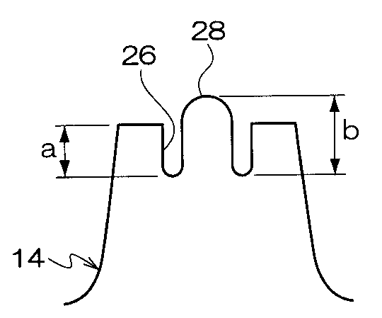
請求項4に記載の発明は、請求項1〜請求項3の何れか1項に記載の二輪車用空気入りタイヤにおいて、トレッド踏面から計測する前記凹部の深さをa、前記凹部の底部から計測する前記突起の高さをbとしたときに、a−b=−2〜+2mmを満足する、ことを特徴としている。 According to a fourth aspect of the present invention, in the pneumatic tire for a motorcycle according to any one of the first to third aspects, the depth of the concave portion measured from the tread surface is measured from the bottom of the concave portion. When the height of the projection is b, a−b = −2 to +2 mm is satisfied.
次に、請求項4に記載の二輪車用空気入りタイヤの作用を説明する。
a−bの値が+2mmよりも+側に大きくなると(突起がブロック踏面よりも低くなる)、突起のエッジが路面に接触するようになるまで、ブロック自体(突起を除いた部分)の摩耗が大きくなり、十分な操縦安定性を確保することが出来なくなる。
Next, the operation of the pneumatic tire for a motorcycle according to claim 4 will be described.
When the value of a−b becomes larger than +2 mm to the + side (the protrusion becomes lower than the block tread surface), the block itself (the part excluding the protrusion) is worn until the edge of the protrusion comes into contact with the road surface. It becomes large and it becomes impossible to ensure sufficient steering stability.
一方、a−bの値が−2mmよりも−側に大きくなると(突起がブロック踏面から2mmよりも突出する)、ブロック内の突起自体が1個のブロックとして作用し、土台となっているブロックを有効に使うことが出来ず、剛性不足や接地面積不足による操縦安定性の低下を招く。
請求項5に記載の発明は、請求項1〜請求項4の何れか1項に記載の二輪車用空気入りタイヤにおいて、前記突起は、ブロック踏面よりも突出している、ことを特徴としている。
On the other hand, when the value of a−b becomes larger than −2 mm to the − side (the protrusion protrudes from the block tread surface more than 2 mm), the protrusion in the block itself acts as one block, and is a base block Cannot be used effectively, leading to a decrease in steering stability due to insufficient rigidity or insufficient ground contact area.
According to a fifth aspect of the present invention, in the pneumatic tire for a motorcycle according to any one of the first to fourth aspects, the protrusion protrudes from the block tread surface.
以上説明したように請求項1に記載の二輪車用空気入りタイヤは上記の構成としたので、現状でのブロックパターン設計を変更する事無く、エッジ効果を増加でき、グリップ、接地感、滑りのコントロール性といった操縦安定性の向上を図ることができる、という優れた効果を有する。 As described above, since the pneumatic tire for a motorcycle according to claim 1 has the above-described configuration, it is possible to increase the edge effect without changing the current block pattern design, and to control grip, feeling of contact, and slip. It has an excellent effect that it is possible to improve the handling stability such as performance.
本発明の一実施形態に係る二輪車用空気入りタイヤ10を図面にしたがって説明する。
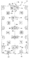
図1は、本実施形態の二輪車用空気入りタイヤ10のトレッド12を平面状に展開して見た平面図である。
A
FIG. 1 is a plan view of a
図1に示すように、トレッド12のタイヤ赤道面CL上には、第1のセンターブロック14、第2のセンターブロック16、第3のセンターブロック18、及び第4のセンターブロック20がタイヤ周方向(矢印A方向(タイヤ回転方向)、及び矢印A方向とは反対方向)に間隔をあけて配置されて中央部ブロック列22を形成している。
As shown in FIG. 1, on the tire equatorial plane CL of the
(中央部ブロック列)
第1のセンターブロック14は、タイヤ幅方向に長い長方形状を呈しており、幅方向中央部には、タイヤ周方向に延びる比較的幅の広い浅溝24が形成されている。なお、浅溝24の深さ寸法は、第1のセンターブロック14の高さ寸法よりも小さい。
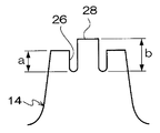
第1のセンターブロック14には、浅溝24の両側に、トレッド平面視で正方形の凹部26が形成されており、凹部26の底部には、トレッド平面視で正方形の突起28が形成されている。
なお、凹部26の側壁と突起28の側壁との間には細溝状の隙間が形成されており、この隙間は、第1のセンターブロック14が路面に接地した際にも消滅しない、即ち、凹部26の側壁と突起28の側壁とが接触しない寸法に設定されている。
(Central block row)
The
In the
In addition, a narrow groove-like gap is formed between the side wall of the
図2の断面図で示すように、ブロック踏面から計測する凹部26の深さをa、凹部26の底部から計測する突起28の高さをbとしたときに、a−b=−2〜+2mmを満足するように凹部26の深さa、及び突起28の高さbを設定することが好ましい。
なお、本実施形態の突起28の頂部(踏面)は、第1のセンターブロック14の踏面と平行に形成されている。
As shown in the sectional view of FIG. 2, when the depth of the
In addition, the top part (tread surface) of the
図1に示すように、第2のセンターブロック16は、第1のセンターブロック14と同様に、タイヤ幅方向に長い長方形状を呈しており、タイヤ幅方向中央部分を境にして両側に、第1のセンターブロック14と同様の突起30を備えた凹部32が形成されている。
As shown in FIG. 1, like the
第3のセンターブロック18は、タイヤ幅方向に長い略長方形状を呈しており、幅方向中央部には、タイヤ周方向に延びる比較的幅の狭い浅溝34が形成されている。なお、浅溝34の深さ寸法は、第3のセンターブロック18の高さ寸法よりも小さい。この第3のセンターブロック18にも、浅溝34の両側に、突起36を備えた凹部38が形成されている。
なお、第4のセンターブロック20は第3のセンターブロック18と同様の形状であるが、ブロックの向きが逆向きに形成されている。
The
The
(中間部ブロック列)
中央部ブロック列22のタイヤ幅方向両側側には、複数の中間部ブロック40がタイヤ周方向に間隔をあけて配置されて中間部ブロック列42を形成している。
中間部ブロック40は、中央部ブロック列22の各ブロックよりも小さく形成されていると共に、トレッド平面視で正方形状を呈しており、中央部にはトレッド平面視で正方形の凹部44が形成され、凹部44の底部にはトレッド平面視で正方形の突起46が1個形成されている。
(Intermediate block row)
A plurality of
The
(トレッド端側ブロック列)
中間部ブロック列42のタイヤ幅方向外側には、複数のトレッド端側ブロック48がタイヤ周方向に間隔をあけて配置されてトレッド端側ブロック列50を形成している。
トレッド端側ブロック48は、トレッド平面視で5角形を呈しており、中央にはトレッド平面視で5角形の凹部52が1個形成されている。
(Tread end side block row)
A plurality of tread end side blocks 48 are arranged at intervals in the tire circumferential direction on the outer side in the tire width direction of the
The
なお、第2のセンターブロック16、第3のセンターブロック18、及び第4のセンターブロック20、及び中間部ブロック40の各凹部の深さa、及び各突起の高さbは、第1のセンターブロック14と同様に設定することが好ましい。
The depth a of each recess and the height b of each protrusion of the
なお、中央部ブロック列22を構成するブロックは、本実施形態の様に1ブロック当たり1個以上の凹部を備えることが好ましい。
本実施形態の様に、中間部ブロック列42を構成するブロック、及びトレッド端側ブロック列50を構成するブロックは、凹部の数を中央部ブロック列22を構成するブロックよりも少なく設定することが好ましい。
また、本実施形態の様に、中央部ブロック列22を構成するブロック、及び中間部ブロック列42を構成するブロックには、突起の形成された凹部を設けることが好ましい。
In addition, it is preferable that the block which comprises the center part block row | line |
As in the present embodiment, the blocks constituting the
In addition, as in the present embodiment, it is preferable that the blocks constituting the
(作用)
本実施形態の二輪車用空気入りタイヤ10においは、中央部ブロック列22を構成する第1のセンターブロック14、第2のセンターブロック16、第3のセンターブロック18、及び第4のセンターブロック20、及び中間部ブロック列42を構成する中間部ブロック40に、踏面側に開口する凹部を形成し、さらにその凹部の底部に突起を形成しているので、凹部(突起の無い)を設けたのみのブロック対比で、突起の分のエッジ成分が増加するため、トラクションを向上させることができる。
なお、本実施形態の二輪車用空気入りタイヤ10では、ブロック踏面でのグリップを向上させる事を目的にゴムの硬度を下げる必要がないので、エッジの摩耗が早くなる問題は生じない。
(Function)
In the
In the
ここで、ブロック自体を大きくした場合、タイヤのネガティブ率も減少するためにブロック接地圧も減少し、泥濘地や軟質路面において十分な初期の突刺し効果が得られなくなるが、本実施形態の二輪車用空気入りタイヤ10では従来対比でブロック自体を大きくする必要が無いため、泥濘地や軟質路面において十分な初期の突刺し効果が得られる。
Here, when the block itself is made larger, the negative rate of the tire also decreases, so the block contact pressure also decreases, and a sufficient initial piercing effect cannot be obtained in muddy areas and soft road surfaces. In the
また、トレッドのゴムの硬度を上げると、硬質路面では十分なブロック踏面のグリップが得られず、突刺し効果やエッジ効果が得られる泥濘地や軟質路面においても、そのゴムの硬さ故に滑りのコントロール性に難があるが、本実施形態の二輪車用空気入りタイヤ10では従来対比でゴムの硬度を上げる必要が無いので、泥濘地や軟質路面における滑りのコントロール性を確保できる。
Also, when the hardness of the tread rubber is increased, sufficient block tread grip cannot be obtained on hard roads, and even on muddy ground and soft roads where piercing effects and edge effects can be obtained, the slipping of the rubber due to the hardness of the rubber Although there is difficulty in controllability, in the
このように、本実施形態の二輪車用空気入りタイヤ10によれば、突起の形成された凹部をブロックに設けるという簡単な構成で、ブロックパターン設計を変更する事無く、エッジ効果を増加でき、グリップ、接地感、滑りのコントロール性といった操縦安定性の向上を図ることができる。
As described above, according to the
なお、本実施形態の二輪車用空気入りタイヤ10によれば、突起の高さをコントロールすることで、硬質路面から泥濘地を含む軟質路面までの広い範囲での操縦安定性向上を実現できる。なお、トレッド踏面から計測する凹部の深さaと凹部の底部から計測する突起の高さbとの差であるa−bの値が+2mmよりもプラス側に大きくなると、突起のエッジが路面に接触するようになるまで、ブロック自体(突起を除いた部分)の摩耗が大きくなり、十分な操縦安定性を確保することが出来なくなる。
In addition, according to the
一方、a−bの値が−2mmよりもマイナス側に大きくなると、ブロック内の突起自体が1個のブロックとして作用し、土台となっているブロックを有効に使うことが出来ず、剛性不足や接地面積不足による操縦安定性の低下を招く。 On the other hand, when the value of a−b becomes larger than −2 mm to the minus side, the protrusions in the block itself act as one block, and the base block cannot be used effectively, and the rigidity is insufficient. This leads to a decrease in handling stability due to insufficient ground contact area.
[その他の実施形態]
上記実施形態では、トレッド端側ブロック48を構成するトレッド端側ブロック48の凹部52には突起が形成されていないが、突起を形成しても良い。
突起を設けた凹部の形成されたブロックは、上記実施形態の配置に限定されるものではなく、本発明の主旨を逸脱しない限り種々の配置変更が可能である。
中央部ブロック列22の各ブロックは、上記実施形態では凹部が2個形成されていたが、凹部の数は1個でも良い。
[Other Embodiments]
In the above embodiment, no protrusion is formed in the
The block in which the concave portion provided with the protrusion is formed is not limited to the arrangement of the above embodiment, and various arrangement changes are possible without departing from the gist of the present invention.
Each block of the
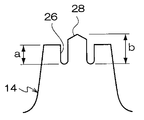
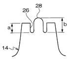
上記実施形態では、図2に示すように突起の断面形状が形成され、突起の頂部(踏面)がブロックの踏面と平行に形成されていたが、本発明はこれに限らず、図3に示すように突起の頂部の断面形状が三角形であっても良く、図4に示すように、突起の頂部の断面形状が円弧形状であっても良い。 In the above embodiment, the cross-sectional shape of the protrusion is formed as shown in FIG. 2, and the top (tread surface) of the protrusion is formed in parallel with the tread surface of the block. However, the present invention is not limited to this, and is shown in FIG. Thus, the cross-sectional shape of the top of the protrusion may be a triangle, and the cross-sectional shape of the top of the protrusion may be an arc as shown in FIG.
(試験例)
本発明の効果を確かめるために、従来例のタイヤ4種、及び本発明の適用された実施例のタイヤ4種を用意し、供試タイヤを実車に装着してプロライダーにより不整地走行による実車評価を行なった。
・従来例のタイヤ:凹部のみを有するブロックを備えたタイヤ。
・実施例のタイヤ:凹部内に突起を有するブロックを備えたタイヤ。
なお、従来例のタイヤ、及び実施例のタイヤ共にパターンは同一である。
・トレッドのネガティブ比:80%
・ブロック高さ:フロント=12.5mm、リア=15.5mm
・ブロック断面形状:図2参照。なお、a=1.5mm、b=2.5mmである。
・タイヤサイズの断面呼び:フロント=80/100、リア=120/80
・タイヤインチ径:フロント=21インチ、リア=19インチ
・実車試験用リム:フロント=1.60×21、リア=2.15×19
・実車試験使用内圧:80kPa
下記の表1の様に8種類のタイヤを試作した。
(Test example)
In order to confirm the effect of the present invention, four types of conventional tires and four types of tires according to the embodiments of the present invention are prepared, and the test tires are mounted on the actual vehicle and the actual vehicle is driven by rough riding by a professional rider. Evaluation was performed.
Conventional tire: a tire having a block having only a recess.
-Tire of Example: A tire provided with a block having a protrusion in a recess.
The pattern is the same for both the conventional tire and the tire of the example.
-Negative ratio of tread: 80%
・ Block height: Front = 12.5mm, Rear = 15.5mm
Block cross-sectional shape: see FIG. Note that a = 1.5 mm and b = 2.5 mm.
・ Cross section of tire size: Front = 80/100, Rear = 120/80
-Tire inch diameter: Front = 21 inches, Rear = 19 inches-Real vehicle test rim: Front = 1.60 x 21, Rear = 2.15 x 19
・ Internal pressure for actual vehicle test: 80kPa
As shown in Table 1 below, eight types of tires were prototyped.
・ラジアル構造:ナイロンコードを含むカーカスプライを1枚使用。カーカスの外周側にア芳香族ポリアミドコード(いわゆるケブラー(商品名)コード)のモノスパイラルベルトが設けられている。
以下の表2に、各タイヤの評価を記載した。評価はプロライダーによるフィーリング評価(10点満点)であり、数値が大きいほど性能に優れていることを表している。
・ Radial structure: One carcass ply including nylon cord is used. A mono-spiral belt made of a aromatic polyamide cord (so-called Kevlar (trade name) cord) is provided on the outer peripheral side of the carcass.
Table 2 below shows the evaluation of each tire. The evaluation is a feeling evaluation by a professional rider (up to 10 points), and the larger the value, the better the performance.
10 二輪車用空気入りタイヤ
12 トレッド
14 第1のセンターブロック
16 第2のセンターブロック
18 第3のセンターブロック
20 第4のセンターブロック
26 凹部
28 突起
30 突起
32 凹部
36 突起
38 凹部
40 中間部ブロック
44 凹部
46 突起
48 トレッド端側ブロック
52 凹部
DESCRIPTION OF
Claims (5)
前記凹部の形成された複数の前記ブロックのうちの少なくとも幾つかは、前記凹部の底部に突起が形成されており、
前記凹部の側壁と前記突起の側壁との間には細溝状の隙間が形成されている、ことを特徴とする二輪車用空気入りタイヤ。 A tread having a plurality of blocks formed with recesses that are open on the tread surface side,
At least some of the plurality of blocks formed with the recesses have protrusions formed at the bottoms of the recesses ,
A pneumatic tire for a motorcycle , wherein a narrow groove-like gap is formed between a side wall of the recess and a side wall of the protrusion .
前記中央部ブロック列を構成する前記ブロックは、1ブロック当たり1個以上の前記凹部を備え、
前記中間部ブロック列を構成する前記ブロック、及び前記トレッド端側ブロック列を構成する前記ブロックは、前記凹部の数が前記中央部ブロック列を構成する前記ブロックよりも少なく設定され、
前記中央部ブロック列を構成する前記ブロック、及び前記中間部ブロック列を構成する前記ブロックには、前記突起の形成された前記凹部を備えている、
ことを特徴とする請求項1に記載の二輪車用空気入りタイヤ。 The tread is arranged at a center block row composed of a plurality of blocks arranged along the circumferential direction in the center in the width direction of the tread, and is arranged on the outer side in the tire width direction of the center block row, and the tread end side of the tread Arranged between the tread end side block row consisting of a plurality of blocks arranged along the circumferential direction, and between the central block row and the tread end side block row, and arranged along the circumferential direction. An intermediate block sequence consisting of a plurality of blocks,
The block constituting the central block row includes one or more concave portions per block,
The blocks constituting the intermediate block row and the blocks constituting the tread end side block row are set to have a smaller number of the recesses than the blocks constituting the central block row,
The block constituting the central block row and the block constituting the intermediate block row are provided with the recesses with the protrusions formed thereon,
The pneumatic tire for a motorcycle according to claim 1.
前記中間部ブロック列を構成する前記ブロックは、前記中央部ブロック列を構成する前記ブロックよりも大きさが小さく、かつ前記突起を備えた前記凹部が1個のみ形成されている、ことを特徴とする請求項1または請求項2に記載の二輪車用空気入りタイヤ。 The block constituting the central block row is formed with one or two of the recesses having the protrusions,
The block constituting the intermediate block row is smaller in size than the block constituting the central block row, and only one concave portion having the protrusion is formed. The pneumatic tire for a motorcycle according to claim 1 or 2.
Priority Applications (4)
| Application Number | Priority Date | Filing Date | Title |
|---|---|---|---|
| JP2008037616A JP5154972B2 (en) | 2008-02-19 | 2008-02-19 | Pneumatic tires for motorcycles |
| PCT/JP2009/052871 WO2009104672A1 (en) | 2008-02-19 | 2009-02-19 | Pneumatic tire for motorcycle |
| US12/918,242 US8875755B2 (en) | 2008-02-19 | 2009-02-19 | Pneumatic tire for motorcycle |
| EP09713493.6A EP2251213B1 (en) | 2008-02-19 | 2009-02-19 | Pneumatic tire for motorcycle |
Applications Claiming Priority (1)
| Application Number | Priority Date | Filing Date | Title |
|---|---|---|---|
| JP2008037616A JP5154972B2 (en) | 2008-02-19 | 2008-02-19 | Pneumatic tires for motorcycles |
Publications (2)
| Publication Number | Publication Date |
|---|---|
| JP2009196425A JP2009196425A (en) | 2009-09-03 |
| JP5154972B2 true JP5154972B2 (en) | 2013-02-27 |
Family
ID=40985550
Family Applications (1)
| Application Number | Title | Priority Date | Filing Date |
|---|---|---|---|
| JP2008037616A Expired - Fee Related JP5154972B2 (en) | 2008-02-19 | 2008-02-19 | Pneumatic tires for motorcycles |
Country Status (4)
| Country | Link |
|---|---|
| US (1) | US8875755B2 (en) |
| EP (1) | EP2251213B1 (en) |
| JP (1) | JP5154972B2 (en) |
| WO (1) | WO2009104672A1 (en) |
Families Citing this family (19)
| Publication number | Priority date | Publication date | Assignee | Title |
|---|---|---|---|---|
| JP5161933B2 (en) * | 2010-07-28 | 2013-03-13 | 住友ゴム工業株式会社 | Motorcycle tires for running on rough terrain |
| BR112013015590A2 (en) * | 2010-12-20 | 2016-10-11 | Michelin & Cie | spline block with reduced thermal wear capabilities |
| JP5174142B2 (en) * | 2010-12-27 | 2013-04-03 | 住友ゴム工業株式会社 | Motorcycle tires for running on rough terrain |
| JP5450515B2 (en) * | 2011-06-10 | 2014-03-26 | 住友ゴム工業株式会社 | Motorcycle tire for rough terrain |
| JP5647642B2 (en) * | 2012-04-09 | 2015-01-07 | 住友ゴム工業株式会社 | Pneumatic tire for running on rough terrain |
| JP5616924B2 (en) * | 2012-04-27 | 2014-10-29 | 住友ゴム工業株式会社 | Pneumatic tire for running on rough terrain |
| US10850567B2 (en) | 2013-04-24 | 2020-12-01 | Bridgestone Corporation | Tire |
| JP6093637B2 (en) * | 2013-04-24 | 2017-03-08 | 株式会社ブリヂストン | tire |
| JP6193731B2 (en) * | 2013-11-07 | 2017-09-06 | 住友ゴム工業株式会社 | Pneumatic tire for running on rough terrain |
| JP5986601B2 (en) * | 2014-06-17 | 2016-09-06 | 住友ゴム工業株式会社 | Motorcycle tires for running on rough terrain |
| JP6420674B2 (en) * | 2015-01-26 | 2018-11-07 | 住友ゴム工業株式会社 | Motorcycle tires for running on rough terrain |
| JP6470582B2 (en) * | 2015-02-17 | 2019-02-13 | 住友ゴム工業株式会社 | Pneumatic tires and pneumatic tires for motorcycles |
| JP6834464B2 (en) * | 2016-12-22 | 2021-02-24 | 住友ゴム工業株式会社 | tire |
| JP6958327B2 (en) * | 2017-12-19 | 2021-11-02 | 住友ゴム工業株式会社 | Motorcycle tires for rough terrain |
| JP7008572B2 (en) * | 2018-05-15 | 2022-01-25 | 株式会社ブリヂストン | Motorcycle tires |
| JP7070071B2 (en) * | 2018-05-15 | 2022-05-18 | 住友ゴム工業株式会社 | Motorcycle tires for rough terrain |
| JP7110784B2 (en) * | 2018-07-19 | 2022-08-02 | 住友ゴム工業株式会社 | tire |
| JP7124531B2 (en) * | 2018-08-01 | 2022-08-24 | 住友ゴム工業株式会社 | tires for rough terrain |
| EP3747673A1 (en) * | 2019-06-05 | 2020-12-09 | Nokian Raskaat Renkaat Oy | Pneumatic vehicle tyre comprising a wear indicator |
Family Cites Families (13)
| Publication number | Priority date | Publication date | Assignee | Title |
|---|---|---|---|---|
| US952039A (en) * | 1908-05-25 | 1910-03-15 | Lemon Greenwald | Non-skid tire. |
| NL137253C (en) * | 1968-12-13 | |||
| JPS573846Y2 (en) | 1977-09-11 | 1982-01-25 | ||
| JPS60110110U (en) * | 1983-12-29 | 1985-07-26 | 住友ゴム工業株式会社 | Tires with improved grip |
| JPS6367304U (en) | 1986-10-22 | 1988-05-06 | ||
| JPH01273706A (en) * | 1988-04-25 | 1989-11-01 | Yokohama Rubber Co Ltd:The | Tread pattern |
| JPH03239606A (en) * | 1990-02-16 | 1991-10-25 | Hishifusa Miura | Slip prevention mechanism for tire or the like |
| JP3021694B2 (en) * | 1991-01-30 | 2000-03-15 | 株式会社ブリヂストン | Pneumatic radial tire |
| JPH0589009U (en) * | 1991-09-17 | 1993-12-03 | 光也 柴 | tire |
| JPH066005U (en) * | 1992-07-02 | 1994-01-25 | 株式会社ブリヂストン | Motorcycle tires |
| JPH06320916A (en) | 1993-05-11 | 1994-11-22 | Yokohama Rubber Co Ltd:The | Pneumatic tire for two-wheeled vehicle |
| FI96934C (en) * | 1994-11-10 | 1996-09-25 | Erkki Antero Myllyharju | vehicle Tires |
| JP4344392B2 (en) * | 2007-05-14 | 2009-10-14 | 住友ゴム工業株式会社 | Motorcycle tires for running on rough terrain |
-
2008
- 2008-02-19 JP JP2008037616A patent/JP5154972B2/en not_active Expired - Fee Related
-
2009
- 2009-02-19 WO PCT/JP2009/052871 patent/WO2009104672A1/en not_active Ceased
- 2009-02-19 US US12/918,242 patent/US8875755B2/en active Active
- 2009-02-19 EP EP09713493.6A patent/EP2251213B1/en not_active Not-in-force
Also Published As
| Publication number | Publication date |
|---|---|
| US8875755B2 (en) | 2014-11-04 |
| US20110024009A1 (en) | 2011-02-03 |
| EP2251213A1 (en) | 2010-11-17 |
| JP2009196425A (en) | 2009-09-03 |
| EP2251213B1 (en) | 2018-12-19 |
| EP2251213A4 (en) | 2012-04-04 |
| WO2009104672A1 (en) | 2009-08-27 |
Similar Documents
| Publication | Publication Date | Title |
|---|---|---|
| JP5154972B2 (en) | Pneumatic tires for motorcycles | |
| JP4272244B2 (en) | Pneumatic tire for running on rough terrain | |
| JP4344392B2 (en) | Motorcycle tires for running on rough terrain | |
| US10293641B2 (en) | Motorcycle tire for uneven ground travel | |
| JP5320491B2 (en) | Motorcycle tires for running on rough terrain | |
| JP4312226B2 (en) | Pneumatic tire for running on rough terrain | |
| JP2010076561A (en) | Pneumatic tire | |
| CN109968911B (en) | Motorcycle tire for running on rough terrain | |
| JP7491009B2 (en) | Motorcycle tires for rough terrain | |
| JP2014141163A (en) | Motorcycle tire for irregular ground running | |
| JP2010023585A (en) | Pneumatic tire for motorcycle | |
| JP5827575B2 (en) | Motorcycle tires for running on rough terrain | |
| JP7070071B2 (en) | Motorcycle tires for rough terrain | |
| JP2003306011A (en) | Tire for motorcycle | |
| JP7298276B2 (en) | Motorcycle tires for rough terrain | |
| US11427034B2 (en) | Tire | |
| JP2020189555A (en) | Motorcycle tire for travelling off road | |
| WO2019151505A1 (en) | Motorcycle tire | |
| JP4326520B2 (en) | Pneumatic tire for running on rough terrain | |
| JP7491010B2 (en) | Motorcycle tires for rough terrain | |
| JP7290056B2 (en) | tire | |
| JP4891614B2 (en) | Pneumatic tire for running on rough terrain | |
| JP2020200000A (en) | Motorcycle tire for traveling uneven road | |
| US20240034097A1 (en) | Motorcycle tire for running on rough terrain | |
| JP2024006707A (en) | Motorcycle tires for riding on rough terrain |
Legal Events
| Date | Code | Title | Description |
|---|---|---|---|
| A621 | Written request for application examination |
Free format text: JAPANESE INTERMEDIATE CODE: A621 Effective date: 20101221 |
|
| A131 | Notification of reasons for refusal |
Free format text: JAPANESE INTERMEDIATE CODE: A131 Effective date: 20120424 |
|
| A521 | Request for written amendment filed |
Free format text: JAPANESE INTERMEDIATE CODE: A523 Effective date: 20120625 |
|
| TRDD | Decision of grant or rejection written | ||
| A01 | Written decision to grant a patent or to grant a registration (utility model) |
Free format text: JAPANESE INTERMEDIATE CODE: A01 Effective date: 20121204 |
|
| A61 | First payment of annual fees (during grant procedure) |
Free format text: JAPANESE INTERMEDIATE CODE: A61 Effective date: 20121206 |
|
| FPAY | Renewal fee payment (event date is renewal date of database) |
Free format text: PAYMENT UNTIL: 20151214 Year of fee payment: 3 |
|
| R150 | Certificate of patent or registration of utility model |
Ref document number: 5154972 Country of ref document: JP Free format text: JAPANESE INTERMEDIATE CODE: R150 Free format text: JAPANESE INTERMEDIATE CODE: R150 |
|
| R250 | Receipt of annual fees |
Free format text: JAPANESE INTERMEDIATE CODE: R250 |
|
| R250 | Receipt of annual fees |
Free format text: JAPANESE INTERMEDIATE CODE: R250 |
|
| R250 | Receipt of annual fees |
Free format text: JAPANESE INTERMEDIATE CODE: R250 |
|
| R250 | Receipt of annual fees |
Free format text: JAPANESE INTERMEDIATE CODE: R250 |
|
| R250 | Receipt of annual fees |
Free format text: JAPANESE INTERMEDIATE CODE: R250 |
|
| R250 | Receipt of annual fees |
Free format text: JAPANESE INTERMEDIATE CODE: R250 |
|
| LAPS | Cancellation because of no payment of annual fees |